KR101688210B1 - Meshed chiral metamaterial - Google Patents
Meshed chiral metamaterialDownload PDFInfo
- Publication number
- KR101688210B1 KR101688210B1KR1020150037191AKR20150037191AKR101688210B1KR 101688210 B1KR101688210 B1KR 101688210B1KR 1020150037191 AKR1020150037191 AKR 1020150037191AKR 20150037191 AKR20150037191 AKR 20150037191AKR 101688210 B1KR101688210 B1KR 101688210B1
- Authority
- KR
- South Korea
- Prior art keywords
- chiral
- metamaterial
- chiral metamaterial
- network
- electromagnetic wave
- Prior art date
- Legal status (The legal status is an assumption and is not a legal conclusion. Google has not performed a legal analysis and makes no representation as to the accuracy of the status listed.)
- Active
Links
Images


Classifications
- G—PHYSICS
- G02—OPTICS
- G02B—OPTICAL ELEMENTS, SYSTEMS OR APPARATUS
- G02B1/00—Optical elements characterised by the material of which they are made; Optical coatings for optical elements
- G02B1/002—Optical elements characterised by the material of which they are made; Optical coatings for optical elements made of materials engineered to provide properties not available in nature, e.g. metamaterials
- G02B1/007—Optical elements characterised by the material of which they are made; Optical coatings for optical elements made of materials engineered to provide properties not available in nature, e.g. metamaterials made of negative effective refractive index materials
- G—PHYSICS
- G02—OPTICS
- G02B—OPTICAL ELEMENTS, SYSTEMS OR APPARATUS
- G02B1/00—Optical elements characterised by the material of which they are made; Optical coatings for optical elements
- G02B1/002—Optical elements characterised by the material of which they are made; Optical coatings for optical elements made of materials engineered to provide properties not available in nature, e.g. metamaterials
- G—PHYSICS
- G02—OPTICS
- G02B—OPTICAL ELEMENTS, SYSTEMS OR APPARATUS
- G02B1/00—Optical elements characterised by the material of which they are made; Optical coatings for optical elements
- G02B1/08—Optical elements characterised by the material of which they are made; Optical coatings for optical elements made of polarising materials
- G—PHYSICS
- G02—OPTICS
- G02B—OPTICAL ELEMENTS, SYSTEMS OR APPARATUS
- G02B5/00—Optical elements other than lenses
- G02B5/30—Polarising elements
Landscapes
- Physics & Mathematics (AREA)
- General Physics & Mathematics (AREA)
- Optics & Photonics (AREA)
- Electrochromic Elements, Electrophoresis, Or Variable Reflection Or Absorption Elements (AREA)
Abstract
Translated fromKoreanDescription
Translated fromKorean본 발명은 그물망 카이랄 메타물질에 관한 것이다. 구체적으로, 본 발명은 광대역에서 무이색성 및 비분산 광활성을 구현할 수 있는 그물망 카이랄 메타물질에 관한 것이다.The present invention relates to a network chiral metamaterial. More specifically, the present invention relates to a network chiral metamaterial capable of realizing non-dichroic and non-dispersive optical activity in a wide band.
편광은 전자기파의 중요하고 기본적인 성질들 중 하나이다. 대부분의 광학 시스템은 입력되는 빛의 편광에 따라 성질이 변하기 때문에 빛의 편광을 조절하는 것은 여러가지 광학 시스템을 디자인하는데 있어서 매우 중요한 요인이다. 일반적으로 편광을 조절하는 방법으로 파장판(waveplate)을 사용하거나 광활성을 갖는 자연계의 카이랄(chiral) 물질을 이용할 수 있다.Polarization is one of the important and fundamental properties of electromagnetic waves. Since most optical systems change properties according to the polarization of input light, adjusting the polarization of light is a very important factor in designing various optical systems. Generally, a waveplate is used as a method of controlling polarization, or a chiral substance of a natural system having a photoactivity can be used.
용어 카이랄은 어떤 거울상 대칭도 가지고 있지 않은 구조적 특성을 의미한다. 카이랄 물질 내에서는 입사되는 전자기파에 의해 발생하는 전기 쌍극자와 자기 쌍극자가 서로 같은 방향으로 상호작용을 하기 때문에 우편광과 좌편광의 축퇴가 깨지게 된다. 따라서, 카이랄 물질은 좌편광과 우편광의 빛에 대해 서로 다른 굴절률을 가지게 되며, 이에 따라 카이랄 물질에 선형 편광의 빛이 입사하면 편광 상태가 회전하는 광활성 특성이 나타나게 된다. 하지만 자연계에 존재하는 카이랄 물질의 광활성은 매우 약하고 공진 주파수 대역에서 분산이 크므로 카이랄 물질을 이용하여 광대역에서 편광을 조절하는 데는 한계가 있다.The term chiral means a structural feature that does not have any mirror symmetry. In the chiral material, since the electric dipole and the magnetic dipole generated by the incident electromagnetic wave interact with each other in the same direction, the degeneration of the postal light and the left polarized light is broken. Therefore, the chiral material has a refractive index different from that of the left-handed polarized light and the postal light, so that when the linearly polarized light is incident on the chiral material, the optically-active property in which the polarized state rotates appears. However, since the optical activity of chiral substances present in nature is very weak and the dispersion is large in the resonance frequency band, there is a limit in controlling the polarization in a wide band using a chiral substance.
최근 광대역 편광을 조절하는데 카이랄 메타물질(Chiral Metamaterial)을 이용하는 기술이 사용되고 있다. 최근 다양한 연구를 통해 카이랄 메타물질이 음굴절률, 비대칭 투과, 극한 광활성 등의 비자연적 광특성을 가질 수 있음이 밝혀졌다. 강하게 공진하는 카이랄 메타 원자 구조를 이용함으로써, 자연계에 존재하는 카이랄 물질의 약한 카이랄 특성보다 매우 큰 강한 카이랄 특성 및 광활성을 획득할 수 있다. 하지만, 카이랄 메타물질을 이용하더라도 공진 특성으로 인해 좁은 투과 대역폭을 가지고 공진 주파수 근처에서 분산에 의해 주파수에 따라 광활성의 크기가 크게 변화한다. 또한, 카이랄 물질의 원편광 이색성(Circular Dichroism)에 의해 카이랄 물질에 입사되는 선형 편광의 빛이 타원 편광으로 변하게 된다. 따라서, 광대역에서 편광 조절을 위해 카이랄 메타물질을 이용하는 데는 역시 한계가 있다.Recently, a technique using a chiral metamaterial has been used to control broadband polarization. Recent studies have revealed that chiral metamaterials can have non-natural optical properties such as negative refractive index, asymmetric transmission, and extreme optical activity. By using a strongly resonating chiral meta-atomic structure, it is possible to obtain a strong chiral characteristic and optical activity which is much larger than the weak chiral characteristic of a chiral substance present in nature. However, even if a chiral metamaterial is used, the magnitude of photoactivity varies greatly depending on the frequency due to dispersion near the resonance frequency due to the narrow transmission bandwidth due to the resonance characteristics. Also, the circularly polarized light incident on the chiral material changes into elliptical polarized light due to the circular dichroism of the chiral substance. Therefore, the use of chiral metamaterials for polarization control in broadband is also limited.
원편광 이색성 및 주파수에 따른 분산 없이 광대역에서 편광 조절이 가능한 기술에 대한 필요성이 대두되고 있다.There is a need for a technique capable of controlling polarization in a wide band without circular polarization dichroism and frequency-dependent dispersion.
본 발명의 목적은 원편광 이색성 없이 광대역에서 비분산 광활성을 나타내는 카이랄 메타물질을 제공하는 것이다.It is an object of the present invention to provide a chiral metamaterial exhibiting non-dispersive photoactivity in a wide band without circular dichroism.
본 발명의 목적은 빛의 편광을 용이하게 조절할 수 있는 효과적인 편광 조절기로 사용될 수 카이랄 메타물질을 제공하는 것이다.It is an object of the present invention to provide a chiral metamaterial which can be used as an effective polarization controller capable of easily controlling the polarization of light.
본 발명에 따른 그물망 카이랄 메타물질은 평면 상에 반복 배열된 복수의 단위 셀을 포함하며, 상기 단위 셀은 복수의 나선구조로 이루어지며, 상기 단위 셀에 포함된 상기 복수의 나선구조는 상기 평면에 대한 법선 방향의 축을 중심으로 회전대칭을 이루도록 구성되고, 상기 복수의 단위 셀 중 이웃하는 단위 셀은 상기 나선구조를 통해 서로 연결된다.The plurality of helix structures included in the unit cell may include a plurality of unit cells arranged in a plane, the unit cell including a plurality of helix structures, And the neighboring unit cells of the plurality of unit cells are connected to each other through the helical structure.
본 발명에 따른 적층형 그물망 카이랄 메타물질은 평면 상에 반복 배열된 복수의 단위 셀을 포함하는 층을 복수 개 포함하며, 상기 복수 개의 층 중 인접한 두 개의 층은 서로 평행하며 소정 거리로 이격되어 적층되어 있고, 상기 단위 셀은 복수의 나선구조로 이루어지며, 상기 단위 셀에 포함된 상기 복수의 나선구조는 상기 평면에 대한 법선 방향의 축을 중심으로 회전대칭을 이루도록 구성되고, 상기 복수의 단위 셀 중 이웃하는 단위 셀은 상기 나선구조를 통해 서로 연결된다.The multilayered network chiral metamaterial according to the present invention includes a plurality of layers including a plurality of unit cells repeatedly arranged on a plane, wherein two adjacent layers of the plurality of layers are parallel to each other, Wherein the unit cells have a plurality of helical structures and the plurality of helical structures included in the unit cells are configured to be rotationally symmetric about an axis in the normal direction to the plane, The neighboring unit cells are connected to each other through the helical structure.
개시된 기술의 실시예들은 다음의 장점들을 포함하는 효과를 가질 수 있다. 다만, 개시된 기술의 실시예들이 이를 전부 포함하여야 한다는 의미는 아니므로, 개시된 기술의 권리범위는 이에 의하여 제한되는 것으로 이해되어서는 아니 될 것이다.Embodiments of the disclosed technique may have effects that include the following advantages. It should be understood, however, that the scope of the disclosed technology is not to be construed as limited thereby, since the embodiments of the disclosed technology are not meant to include all such embodiments.
본 발명에 따르면, 원편광 이색성 없이 광대역에서 비분산 광활성을 나타내는 카이랄 메타물질을 제공할 수 있다.INDUSTRIAL APPLICABILITY According to the present invention, it is possible to provide a chiral metamaterial exhibiting non-dispersive photoactivity in a wide band without circular dichroism.
또한, 본 발명에 따르면 빛의 편광을 용이하게 조절할 수 있는 효과적인 편광 조절기로 사용될 수 카이랄 메타물질을 제공할 수 있다.In addition, according to the present invention, it is possible to provide a chiral metamaterial which can be used as an effective polarization controller capable of easily controlling the polarization of light.
또한, 본 발명에 따르면 나선구조들이 그물망을 이루고 있어 전류가 구조 내에서 자유롭게 흘러 투과 대역이 비공진 모드에서 존재하게 하고 이러한 비공진 특성에 의해 주파수에 상관없이 일정한 광활성을 가질 수 있는 그물망 카이랄 메타물질을 제공할 수 있다.According to the present invention, since the spiral structures form a network, the current flows freely in the structure, and the transmission band exists in the non-resonance mode. By this non-resonance characteristic, Lt; / RTI >
또한, 본 발명에 따르면 광대역에서 입사되는 빛의 파장 이하의 두께에서도 빛의 편광을 마음대로 조절할 수 있는 효과적인 편광 조절기로 사용될 수 있는 그물망 카이랄 메타물질을 제공할 수 있다.In addition, according to the present invention, it is possible to provide a chiral chiral metamaterial which can be used as an effective polarization controller capable of arbitrarily controlling the polarization of light even at a wavelength below the wavelength of light incident at a wide band.
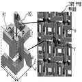
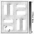
도 1(a)는 실시예에 따른 그물망 카이랄 메타물질의 구조를, 도 1(b)는 도 1(a)의 구조의 z=h/2평면에서 자기장 분포를, 그리고 도 1(c)는 도 1(a)의 구조로 제작된 샘플의 사진을 도시한다.
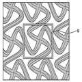
도 2(a) 내지 2(c)는 단일 나선구조를 갖는 다른 실시예에 따른 그물망 카이랄 메타물질의 구조를 도시한다.
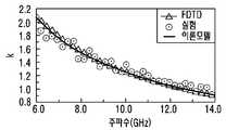
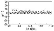
도 3(a) 내지 3(d)는 각각 실시예에 따른 단일층 그물망 카이랄 메타물질의 총투과율, 카이랄 파라미터, 편광 회전도 및 원편광 이색성을 나타내는 그래프이다.
도 4(a) 및 4(b)는 각각 실시예에 따른 그물망 카이랄 메타물질에 포함된 나선의 두께에 따른 편광 회전도와 주파수 10GHz에서 나선의 두께에 따른 편광 회전도를 나타내는 그래프이다.
도 5(a) 및 5(b)는 각각 실시예에 따른 2개의 층 사이의 거리에 따른 이층형 그물망 카이랄 메타물질의 총투과율을 나타내는 그래프 및 편광 회전도 및 이심율을 나타내는 그래프이다.
도 6(a) 내지 6(c)는 각각 실시예에 따른 3층, 4층 및 5층형 그물망 카이랄 메타물질의 총투과율 및 편광 회전도를 층간 거리의 함수로 나타내는 그래프이다.
도 7(a) 내지 7(c)는 각각 실시예에 따른 그물망 카이랄 메타물질의 적외선 대역에서의 총투과율, 편광 회전도 및 원편광 이색성을 나타내는 그래프이다.1 (b) shows the magnetic field distribution in the z = h / 2 plane of the structure of FIG. 1 (a), and FIG. 1 (c) Shows a photograph of a sample made with the structure of Fig. 1 (a).
Figures 2 (a) -2 (c) illustrate the structure of a network chiral metamaterial according to another embodiment having a single helix structure.
3 (a) to 3 (d) are graphs showing the total transmittance, chiral parameter, polarization rotation, and circular polarization dichroism of the single-layer network chiral metamaterial according to each example.
4 (a) and 4 (b) are graphs showing the polarization rotation according to the thickness of the helix included in the network chiral metamaterial according to the embodiment and the polarization rotation according to the thickness of the helix at the frequency of 10 GHz, respectively.
FIGS. 5 (a) and 5 (b) are graphs showing the total transmittance of the bilayer chiral metamaterial according to the distance between two layers according to the embodiment, and the graphs showing the polarization rotation and the eccentricity, respectively.
6 (a) to 6 (c) are graphs showing the total transmittance and the polarization rotation degree of the three-layer, four-layer and five-layer network chiral metamaterial according to the embodiments as a function of the interlayer distance.
7 (a) to 7 (c) are graphs showing total transmittance, polarization rotation and circular polarization dichroism in the infrared band of the network chiral metamaterial according to the embodiment, respectively.
후술하는 본 발명에 대한 상세한 설명은, 본 발명이 실시될 수 있는 특정 실시예를 예시로서 도시하는 첨부 도면을 참조한다. 이들 실시예는 당업자가 본 발명을 실시할 수 있기에 충분하도록 상세히 설명된다. 본 발명의 다양한 실시예는 서로 다르지만 상호 배타적일 필요는 없음이 이해되어야 한다.The following detailed description of the invention refers to the accompanying drawings, which illustrate, by way of illustration, specific embodiments in which the invention may be practiced. These embodiments are described in sufficient detail to enable those skilled in the art to practice the invention. It should be understood that the various embodiments of the present invention are different, but need not be mutually exclusive.
실시예에 따른 그물망 카이랄 메타물질은 평면 상에 반복 배열된 복수의 단위 셀을 포함하며, 상기 단위 셀은 복수의 나선구조로 이루어지며, 상기 단위 셀에 포함된 상기 복수의 나선구조는 상기 평면에 대한 법선 방향의 축을 중심으로 회전대칭을 이루도록 구성되고, 상기 복수의 단위 셀 중 이웃하는 단위 셀은 상기 나선구조를 통해 서로 연결되어 있을 수 있다.According to an embodiment, the network chiral metamaterial includes a plurality of unit cells repeatedly arranged on a plane, the unit cells having a plurality of helical structures, and the plurality of helical structures included in the unit cells are arranged in the plane And the neighboring unit cells of the plurality of unit cells may be connected to each other through the helical structure.
도 1(a)는 실시예에 따른 그물망 카이랄 메타물질의 구조를, 도 1(b)는 도 1(a)의 구조의 z=h/2평면에서 자기장 분포를, 그리고 도 1(c)는 도 1(a)의 구조로 제작된 샘플의 사진을 도시한다.1 (b) shows the magnetic field distribution in the z = h / 2 plane of the structure of FIG. 1 (a), and FIG. 1 (c) Shows a photograph of a sample made with the structure of Fig. 1 (a).
도 1(a)의 우측에 실시예에 따른 그물망 카이랄 메타물질의 전체 구조가 도시된다. 실시예에 따른 그물망 카이랄 메타물질(MHM)은 나선구조를 복수 개 포함하여 구성된 단위 셀(u)이 반복 결합되는 구조를 갖는다. 이때, 복수 개의 단위 셀(u)이 배열된 평면은 가상의 평면일 수 있으며 복수 개의 단위 셀(u)이 2차원 평면으로 배열되어 있는 것으로 충분하다. 도 1(a)에서는 단위 셀(u)이 4개의 나선구조를 포함하여 구성되는 경우를 예시하며, 좌측에 하나의 나선구조가 확대되어 도시되어 있다.On the right side of FIG. 1 (a), the overall structure of the network chiral metamaterial according to the embodiment is shown. The mesogenic chiral metamaterial (MHM) according to the embodiment has a structure in which a unit cell (u) including a plurality of helical structures is repeatedly bonded. At this time, the plane in which the plurality of unit cells u are arranged may be a virtual plane, and it is sufficient that the plurality of unit cells u are arranged in a two-dimensional plane. FIG. 1 (a) illustrates a case where the unit cell u includes four helical structures, and one helical structure on the left side is enlarged.
실시예에 따른 그물망 카이랄 메타물질을 형성하는 나선구조는 금속으로 이루어질 수 있다. 실시예에 따른 나선구조를 이루는 금속은 구리, 금, 은과 같은 저항이 낮은 금속일 수 있다. 또한, 실시예에 따른 나선구조를 이루는 금속으로는 전술한 금속보다 저항이 큰 금속이 이용될 수 있으나, 이러한 경우 주파수에 따른 광활성의 분산이 다소 생길 수 있고 금속 내로 전기장이 침투하게 되어 광활성의 전체적인 크기가 약간 작아질 수 있다. 하지만, 이러한 경우에도 본 발명의 실시예에서 달성하고자 하는 비분산 광활성의 성질은 유지될 수 있다.The spiral structure for forming the network chiral metamaterial according to the embodiment may be made of metal. The metal forming the spiral structure according to the embodiment may be a metal having low resistance such as copper, gold, silver. In addition, a metal having a resistance higher than that of the metal may be used as the metal forming the spiral structure according to the embodiment. However, in this case, the dispersion of the photoactive activity depending on the frequency may be somewhat generated and the electric field penetrates into the metal, The size may be slightly smaller. However, even in such a case, the nature of the non-dispersive photoactivity to be achieved in the embodiment of the present invention can be maintained.
도 1(a)에서 나선구조는 이중 나선구조인 것이 예시되어 있다. 이중 나선구조H1 및 H2가 서브 셀(su)에 포함되어 있다. 실시예에서 하나의 나선구조만을 포함하도록 구성될 수 있다. 이중 나선구조를 이용하면 하나의 나선구조를 이용하는 경우에 비해 광활성의 크기를 더 크게 할 수 있다.In Fig. 1 (a), the helical structure is a double helical structure. The double helix structures H1 and H2 are contained in the subcell (su). In an embodiment, it may be configured to include only one spiral structure. By using the double helix structure, the magnitude of photoactivity can be made larger than that of using one helical structure.
인접한 단위 셀(u)들은 이들 각각에 포함된 나선구조들을 통해 서로 연결될 수 있다. 이때, 실시예에 따른 그물망 카이랄 메타물질에 포함되는 모든 나선구조들은 결과적으로 서로 전기적으로 연결되어 그물망을 이룰 수 있다. 전기적으로 연결된다는 것은 서로 간에 전류가 흐를 수 있도록 직접 또는 간접적으로 연결된 것을 의미한다. 나선구조들은 하나의 단위 셀(u)이 4중 또는 6중 회전대칭을 이루되 모든 축(x, y, z)에 대해서 거울상 대칭을 이루지 않도록 연결되어야 한다.Adjacent unit cells u may be connected to each other via the spiral structures included in each of them. At this time, all of the spiral structures included in the meshed chiral metamaterial according to the embodiment may be electrically connected to each other to form a mesh. Electrical connection means directly or indirectly connected so that current flows between them. The helical structures should be connected such that one unit cell (u) forms a quadruple or a six-fold rotational symmetry and does not mirror-symmetry with respect to all axes (x, y, z).
하나의 단위 셀(u)에서 나선구조들은 단위 셀(u)이 배열된 평면의 법선 방향의 축을 따라 회전대칭을 이루도록 구성될 수 있다. 예컨대, 도 1(a)에서 단위 셀(u)의 중심(c)에서 z축을 따라 회전하는 경우 단위 셀(u)이 4중 회전대칭을 가지도록 구성되어 있다. 즉, 단위 셀(u)을 회전축을 따라 90도 회전할 때마다 회전하기 전의 단위 셀(u)과 동일한 형상이 나타난다. 도 1(a)에서는 단위 셀(u)의 나선구조들이 4중 회전대칭을 이루도록 구성된 것이 예시되나, 실시예에 따라 6중 회전대칭을 이루도록 구성될 수 있다. 단위 셀(u)이 4중 회전대칭 및 6중 회전대칭을 이루도록 구성될 때 실시예에 따른 그물망 카이랄 메타물질이 원편광을 고유분극(eigen polarization)으로 가지는 규칙적인 격자를 구성할 수 있다.The spiral structures in one unit cell u may be configured to be rotationally symmetric along the normal axis of the plane in which the unit cells u are arranged. For example, when the unit cell u rotates along the z axis at the center c of the unit cell u in Fig. 1 (a), the unit cell u is configured to have quadruple rotational symmetry. That is, every time the unit cell u is rotated 90 degrees along the rotation axis, the same shape as the unit cell u before rotation appears. In FIG. 1 (a), the helical structures of the unit cell u are configured to have quadruple rotational symmetry, but they may be configured to have a six-fold rotational symmetry according to the embodiment. When the unit cell u is configured to have a quadruple rotational symmetry and a six-fold rotational symmetry, the network chiral metamaterial according to the embodiment can form a regular lattice having circular polarization as an eigen polarization.
이러한 그물망 카이랄 메타물질의 회전대칭성은 회전 축 방향에서 정면 입사된 전자기파의 고유분극이 원편광이 되도록 만든다. 고유분극이 원편광이기 때문에 선형 편광을 갖는 전자기파가 어떠한 편광 각도로 입사되더라도 동일한 광활성의 크기를 가질 수 있다. 이러한 특성은 선형 편광 이색성을 갖는 파장판 등의 특성과는 매우 다른 것이다.The rotational symmetry of such a chiral chiral metamaterial causes the intrinsic polarization of the electromagnetic wave incident on the front surface in the direction of the axis of rotation to be circularly polarized. Since the intrinsic polarization is circularly polarized light, the electromagnetic wave having linearly polarized light can have the same optical activity regardless of the polarization angle. These properties are very different from those of wave plates with linear polarization dichroism.
그물망 카이랄 메타물질에 전자기파가 입사되면 유도된 전류 모멘트에 의해 강한 자기 모멘트(M)가 나선축 방향으로 생성된다. 이러한 자기 모멘트(M)는 나선축 방향의 전기장(E) 또는 자기장(H)에 의해 유도될 수 있다.When the electromagnetic wave is incident on the mesh chiral metamaterial, a strong magnetic moment (M) is generated in the direction of the helical axis by the induced current moment. This magnetic moment M can be induced by the electric field E or the magnetic field H in the helical axis direction.
도 1(b)에는 전기장이 x축 방향으로 편광되어 있는 전자기파가 그물망 카이랄 메타물질(MHM)에 z축 방향으로 입사되었을 때 z=h/2 평면에서 단위 셀(u)의 자기장(H) 분포를 나타낸다. 도 1(b)에서 알 수 있는 바와 같이, 입사되는 전기장의 방향(x축 방향)과 유도된 자기장의 방향이 같아지며 이로 인해 더욱 강한 광활성을 획득할 수 있다.1 (b) shows the magnetic field H of the unit cell u at the z = h / 2 plane when an electromagnetic wave polarized in the x-axis direction is incident on the mesh chiral metamaterial MHM in the z- Distribution. As can be seen from Fig. 1 (b), the direction of the incident electric field (x-axis direction) is the same as the direction of the induced magnetic field, and thus a stronger optical activity can be obtained.
도 1(c)에는 도 1(a)의 구조로 제작된 샘플의 사진을 도시한다. 도 1(c)에서 샘플은 170 X 170mm의 크기로 제작되고 도 1(c)에서 단위 원시 셀(primitive unit cell)이 표시되어 있으며 단위 원시 셀의 격자상수는 α=3.66mm로 제작되고, 구조적 수치들은 a=2.59mm, b=1.15mm, w=0.50mm 그리고 h=2.5mm로 제작되었다. 본 명세서에서 상기 샘플이 이하에서 언급하는 실험에서 사용되었다. 본 명세서에서 실험을 위한 샘플은 마이크로웨이브(microwave: 예컨대 6GHz 내지 14GHz)에서 동작하도록 설계되었다. 또한, 본 명세서 실험을 위한 샘플은 전자기파가 단일층의 그물망 카이랄 메타물질을 통과할 때마다 편광이 45도 회전하도록 설계되었다.Fig. 1 (c) shows a photograph of a sample made with the structure of Fig. 1 (a). In FIG. 1C, a sample is fabricated with a size of 170 X 170 mm, a primitive unit cell is shown in FIG. 1 (c), a lattice constant of a unit primitive cell is made to be 3.66 mm, The figures were made a = 2.59mm, b = 1.15mm, w = 0.50mm and h = 2.5mm. In this specification, the sample was used in the experiments mentioned below. Samples for the experiments herein are designed to operate in a microwave (e.g., 6 GHz to 14 GHz). In addition, the sample for the experiment herein was designed to rotate the polarization by 45 degrees every time an electromagnetic wave passes through a single layer of networked chiral metamaterial.
도 1(a) 내지 1(c)를 참조하여 설명한 나선구조의 형태 및 제작 수치는 단지 예시일 뿐이며 실시예에 따라 다른 현태 및 수치로 그물망 카이랄 메타물질이 제작될 수 있음은 자명하다.1 (a) to 1 (c) is merely an example, and it is obvious that a network chiral metamaterial can be manufactured according to different embodiments and numerical values according to the embodiment.
도 2(a) 내지 2(c)는 단일 나선구조를 갖는 다른 실시예에 따른 그물망 카이랄 메타물질의 구조를 도시한다. 도 2(a) 내지 2(c)에서는 단일 나선구조를 갖고 4중 회전대칭을 이루는 실시예에 따른 그물망 카이랄 메타물질을 예시한다. 도 2(a) 내지 2(c)에서는 단위 셀(u)이 정육각형 또는 사각형 테두리로 표시되어 있다. 도 2(a) 내지 2(c)에서 모두 단일 나선구조 및 4중 회전대칭을 갖는 그물망 카이랄 메타물질의 구조가 예시되나, 나선구조가 서로 다른 것을 알 수 있다. 이상으로부터 알 수 있는 바와 같이, 실시예에 따른 그물망 카이랄 메타물질의 나선구조는 다양한 형태를 가질 수 있다.Figures 2 (a) -2 (c) illustrate the structure of a network chiral metamaterial according to another embodiment having a single helix structure. Figures 2 (a) -2 (c) illustrate a chiral chiral metamaterial according to an embodiment having a single helix structure and quadruple rotational symmetry. 2 (a) to 2 (c), the unit cell u is represented by a regular hexagon or a quadrangular frame. In FIGS. 2 (a) to 2 (c), the structures of the chiral chiral metamaterial having a single helical structure and a quadruple rotational symmetry are exemplified, but the helical structures are different from each other. As can be seen from the above, the spiral structure of the network chiral metamaterial according to the embodiment can have various forms.
도 3(a) 내지 3(d)는 각각 실시예에 따른 단일층 그물망 카이랄 메타물질의 총투과율, 카이랄 파라미터, 편광 회전도 및 원편광 이색성을 나타내는 그래프이다.3 (a) to 3 (d) are graphs showing the total transmittance, chiral parameter, polarization rotation, and circular polarization dichroism of the single-layer network chiral metamaterial according to each example.
본 명세서에서 실험은 선형 편광이 되어 있는 광대역 혼-안테나(horn antenna)와 네트워크 분석기를 이용하여 투과율을 측정하였다. 실시예에 따른 그물망 카이랄 메타물질의 카이랄성을 특정하기 위해 편광 회전도와 원편광 이색성을 상기 투과율로부터 계산하였다. 편광 회전도(θ)의 값은


다시 도 3(a)에서는 실시예에 따른 단일층 그물망 메타물질(MHM)을 투과한 전자기파의 총 투과율을 나타내는 그래프이다. 삼각형으로 표시된 실선은 수치해석을 통해 얻어진 FDTD(finite-difference time-domain) 시뮬레이션 데이터이고 원 표시는 실험을 통해 획득된 값이다. 이때 총 투과율(Ttot)은
도 3(b)에서는 실험을 통해 추출된 카이랄 파라미터와 시뮬레이션을 통해 획득된 카이랄 파라미터의 값을 비교하는 그래프를 도시한다. 도 3(b)에서 시뮬레이션을 통해 획득된 카이랄 파라미터와 실험치가 거의 일치함을 알 수 있다. 도 3(b)에서 굵은 실선은 추후에 설명될 이론모델을 통해 획득된 데이터를 나타내며 이를 통해 실시예에 따른 그물망 카이랄 메타물질의 카이랄 파라미터(k)가 주파수의 역수에 비례하여 감소함을 알 수 있다.3 (b) shows a graph comparing the values of the chiral parameters extracted through the experiment with the values of the chiral parameters obtained through the simulation. In FIG. 3 (b), it can be seen that the experimental values are almost identical to the chiral parameters obtained through the simulation. In FIG. 3 (b), a bold solid line represents data obtained through a theoretical model to be described later, whereby the chiral parameter (k) of the network chiral metamaterial according to the embodiment decreases in proportion to the reciprocal of the frequency Able to know.
이러한 카이랄 파라미터의 경향성을 통해 실시예에 따른 그물망 카이랄 메타물질이 주파수에 무관하게 비분산 광활성을 갖는 것으로 해석할 수 있다. 이는 카이랄 파리미터(k)와 광활성을 나타내는 편광 회전도(θ) 사이에
도 3(c)에서는 실시예에 따른 그물망 카이랄 메타물질이 비분산 광활성을 가지는 것을 직접적으로 보여준다. 도 3(c)에서 실시예에 따른 그물망 카이랄 메타물질에 입사된 선형 편광된 빛은 그물망 카이랄 메타물질을 통과 후에 주파수에 상관없이 편광 상태가 45도 회전됨을 알 수 있다. 도 3(d)에서 알 수 있는 바와 같이 원편광 이색성이 존재하지 않으므로(η=0), 입사된 선형 편광된 전자기파는 그물망 카이랄 메타물질을 통과 후에도 선형 편광 상태를 유지할 수 있다.In FIG. 3 (c), it is directly shown that the mesogenic chiral metamaterial according to the embodiment has non-dispersing photocatalytic activity. In FIG. 3 (c), the linearly polarized light incident on the mesh chiral metamaterial according to the embodiment is rotated 45 degrees regardless of the frequency after passing through the mesh chiral metamaterial. As can be seen in FIG. 3 (d), since the circular polarization dichroism does not exist (eta = 0), the incident linearly polarized electromagnetic wave can maintain the linear polarization state even after passing through the network chiral metamaterial.
이때, 실시예에 따른 단일층 그물망 카이랄 메타물질의 두께는 입사된 전자기파의 파장에 비해서도 매우 작으므로(예컨대, 파장길의 1/5), 실시예에 따른 그물망 카이랄 메타물질을 이용할 경우 파장 이하의 작은 두께로도 빛의 편광을 광대역에서 자유롭게 조절할 수 있다.In this case, since the thickness of the monolayer chiral chiral metamaterial according to the embodiment is much smaller than the wavelength of the incident electromagnetic wave (for example, 1/5 of the wavelength lane), when the chiral metamaterial according to the embodiment is used, It is possible to freely adjust the polarization of light in a wide band.
실시예에 따른 그물망 카이랄 메타물질의 비분산 광활성 특성은 드루드(Drude-like)한 성질로 인해 발생한다고 해석될 수 있다. 일반적인 유전체 카이랄 메타물질(즉, 공진형 카이랄 메타물질)의 경우에는 단위 셀의 구조에 전류 모드가 국지화되므로 전류가 일반적인 LC 공진 형태를 띄고 공진 주파수에서 강한 분산을 나타낸다. 실시예에 따른 그물망 카이랄 메타물질에서는 나선구조들이 서로 그물망을 이루고 있어 전류가 그물망 카이랄 메타물질에서 자유롭게 흐르게 된다. 이러한 특성에 의해 실시예에 따른 그물망 카이랄 메타물질은 드루드 타입 카이랄 메타물질로 분류될 수 있다.It can be interpreted that the non-dispersed photoactive property of the mesogenic chiral metamaterial according to the embodiment occurs due to the Drude-like property. In the case of a general dielectric chiral metamaterial (that is, a resonant chiral metamaterial), the current mode is localized in the structure of the unit cell, so that the current exhibits a general LC resonance form and exhibits strong dispersion at the resonance frequency. In the mesh chiral metamaterial according to the embodiment, the spiral structures are meshed with each other, so that current flows freely in the mesh chiral metamaterial. By such a characteristic, the network chiral metamaterial according to the embodiment can be classified as a druid type chiral metamaterial.
실시예에 따른 그물망 카이랄 메타물질의 비공진 특성은 이하의 전자의 운동 방정식을 기초로 한 간단한 이론모델을 통해 이해될 수 있다. 그물망 카이랄 메타물질에서 그물망을 형성하는 나선구조들이 오직 나선축 방향으로만 전기 모멘트와 자기 모멘트를 형성한다고 가정하면, 단일층 그물망 카이랄 메타물질 내에서 평균 전기장(D)과 평균 자기장(B)은 아래와 같이 표현될 수 있다.The non-resonance characteristics of a network chiral metamaterial according to an embodiment can be understood through a simple theory model based on the following equation of motion of electrons. (D) and average magnetic field (B) in a single-layer network chiral metamaterial, assuming that the spiral structures forming the network in the chiral metamaterial form electrical moment and magnetic moment only in the helical axis direction. Can be expressed as follows.


여기서, A는 나선구조의 루프(loop) 넓이로서 나선구조의 회전축 방향에 대한 나선구조의 단면적, 그리고 V0는 단위 셀의 부피를 나타낸다. ε0 및 μ0는 각각 진공에서의 유전율 및 투자율을 나타낸다. 단위 셀(u)에서 모든 나선구조들은 인덕턴스 L 및 저항 R을 갖는다고 가정되었다. 여기서, 일반적인 카이랄 물질의 구성 방정식과 전술한 수학식(1) 및 (2)를 비교하면, 실시예에 따른 그물망 카이랄 메타물질의 유효 카이랄 파라미터(k)가 아래와 같이 예측될 수 있다.Where A is the loop width of the spiral structure, the cross-sectional area of the spiral structure in the direction of the rotation axis of the spiral structure, and V0 is the volume of the unit cell.0 and0 denote the permittivity and the permeability at vacuum, respectively. It is assumed that all the helical structures in the unit cell (u) have an inductance L and a resistance R. Here, the effective chiral parameter (k) of the network chiral metamaterial according to the embodiment can be predicted as follows by comparing the constitutive equations of a general chiral substance with the above-mentioned equations (1) and (2).

카이랄 파라메터의 값들을 살펴보면, 저항이 상대적으로 작거나 주파수가 높아질 때 카이랄 파리미터의 값이 거의 실수이고 ω-1의 경향성을 가짐을 알 수 있다. 인덕턴스(L)의 값을 적당하게 설정하고 마이크로웨이브 파장 대역에서는 금속에서 손실이 거의 없으므로 손실이 없는 것으로 가정하면(R=0), 도 3(b) 내지 3(d)에서와 같이 시뮬레이션 결과 및 실험결과가 위의 이론모델의 결과와 거의 일치하는 것을 확인할 수 있다. 하지만, 메타물질에 큰 손실(즉, 큰 옴 저항: ohmic resistance)이 있다고 가정하더라도 k의 허수부는 주파수에 따라 ω-2의 경향성을 가지고 감소하므로 투과 대역에서는 카이랄 파리메터(k)의 값이 거의 실수 값을 갖는다고 간주될 수 있다. 따라서, 실시예에 따른 그물망 카이랄 메타물질의 손실 여부와는 거의 무관하게 해당 그물망 카이랄 메타물질에 입사된 선형 편광된 전자기파는 선형 편광을 그대로 유지하면서 해당 물질을 투과하는 것을 알 수 있다.When we look at the values of the chiral parameters, it can be seen that when the resistance is relatively small or the frequency is high, the value of the chiral parameter is almost a real number and has a tendency of ω-1 . Assuming that the inductance (L) is appropriately set and that there is no loss in the microwave wavelength band because there is little loss in the metal (R = 0), the results of the simulation as shown in Figs. 3 (b) It can be seen that the experimental results are almost in agreement with the results of the above theoretical model. However, even if we assume that the metamaterial has a large loss (ie, ohmic resistance), the imaginary part of k decreases with the tendency of ω-2 depending on the frequency, so the value of the chiral paramater (k) It can be regarded as having almost a real value. Therefore, it can be seen that the linearly polarized electromagnetic wave incident on the mesh chiral metamaterial substantially regardless of the loss of the network chiral metamaterial according to the embodiment transmits the material while maintaining the linear polarization.
본 명세서에서 실험에 사용된 샘플의 설계 파라미터들은 단일층의 그물망 메타물질의 통과시 편광 회전도가 45도가 되도록 선택되었다. 하지만, 이러한 편광 회전도는 나선구조의 두께를 조절함으로써 간단히 조절될 수 있다.The design parameters of the samples used in the experiments herein were chosen so that the polarization rotations when passing through a single layer of the network metamaterial were 45 degrees. However, this polarization rotation can be simply controlled by adjusting the thickness of the spiral structure.
도 4(a) 및 4(b)는 각각 실시예에 따른 그물망 카이랄 메타물질에 포함된 나선의 두께에 따른 편광 회전도와 주파수 10GHz에서 나선의 두께에 따른 편광 회전도를 나타내는 그래프이다.4 (a) and 4 (b) are graphs showing the polarization rotation according to the thickness of the spiral included in the network chiral metamaterial according to the embodiment and the polarization rotation according to the thickness of the spiral at the frequency of 10 GHz, respectively.
도 4(a)는 나선구조의 두께(t)에 따라 수치해석으로 계산된 단일층 그물망 카이랄 메타물질을 통과한 전자기파의 편광 회전도를 나타낸다. 도 4(a)로부터, 나선구조의 두께(t)가 증가할수록 광활성의 크기가 커지고 광활성의 비분산성은 두께에 무관하게 유지되는 것을 알 수 있다. 이러한 두께에 따른 광활성 경향은 도 4(b)를 통해 더 명확히 확인할 수 있다. 도 4(b)에서는 10GHz에서 나선구조의 두께(t)에 따른 편광 회전도를 보여준다.Fig. 4 (a) shows the polarization rotation of electromagnetic waves passing through a monolayer chiral chiral metamaterial calculated by a numerical analysis according to the thickness (t) of the helical structure. From FIG. 4 (a), it can be seen that as the thickness t of the helical structure increases, the magnitude of the photoactive activity increases and the non-dispersive property of the photoactive property is maintained regardless of the thickness. The photoactivity tendency depending on the thickness can be more clearly confirmed through FIG. 4 (b). 4 (b) shows the polarization rotation according to the thickness t of the spiral structure at 10 GHz.
도 4(a) 및 4(b)에서는 나선구조의 단면이 한 변의 길이가 t인 정사각형인 경우를 예시하나, 나선구조의 단면은 직사각형, 원, 타원 등 임의의 형태를 가질 수 있다. 예컨대, 나선구조의 단면이 2개의 인접한 변의 길이가 t1 및 t2인 직사각형일 때, 도 4(a) 및 도4(b) 등에서 t=(t1+t2)/2일 수 있다.In FIGS. 4 (a) and 4 (b), the cross section of the helical structure is a square having a length of t, but the cross section of the helical structure may have any shape such as a rectangle, a circle, and an ellipse. For example, when the cross section of the helical structure is a rectangle in which the lengths of two adjacent sides are t1 and t2, t = (t1 + t2) / 2 in Figs. 4A and 4B.
이러한 경향성은 전술한 이론모델을 통해서도 예측될 수 있다. 나선구조의 인덕턴스(L)을

여기서, 편광 회전도(θ)와 나선구조의 두께(t) 사이에 선형 관계가 있음을 알 수 있다. 이러한 선형 관계는 도 4(b)에 점선으로 표시된 시뮬레이션 결과와 함께 실선으로 표시되어 있으며 두 데이터가 서로 잘 매칭(matching)되는 것을 알 수 있다.Here, it can be seen that there is a linear relationship between the polarization rotation degree [theta] and the thickness t of the helical structure. This linear relationship is indicated by a solid line together with the simulation result indicated by the dotted line in FIG. 4 (b), and it can be seen that the two data are well matched to each other.
실시예에 따른 적층형 그물망 카이랄 메타물질은 평면 상에 반복 배열된 복수의 단위 셀을 포함하는 층을 복수 개 포함할 수 있으며, 상기 복수 개의 층 중 인접한 두 개의 층은 서로 평행하며 소정 거리로 이격되어 적층되어 있고, 상기 단위 셀은 복수의 나선구조로 이루어지며, 상기 단위 셀에 포함된 상기 복수의 나선구조는 상기 평면에 대한 법선 방향의 축을 중심으로 회전대칭을 이루도록 구성되고, 상기 복수의 단위 셀 중 이웃하는 단위 셀은 상기 나선구조를 통해 서로 연결될 수 있다.The stacked-type network chiral metamaterial according to an embodiment may include a plurality of layers including a plurality of unit cells repeatedly arranged on a plane, wherein two adjacent layers of the plurality of layers are parallel to each other, Wherein the plurality of helical structures included in the unit cells are configured to be rotationally symmetric about an axis in the normal direction to the plane, Neighboring unit cells of the cells may be connected to each other through the helical structure.
도 5(a) 및 5(b)는 각각 실시예에 따른 2개의 층 사이의 거리에 따른 이층형 그물망 카이랄 메타물질의 총투과율을 나타내는 그래프 및 편광 회전도 및 이심율을 나타내는 그래프이다.FIGS. 5 (a) and 5 (b) are graphs showing the total transmittance of the bilayer chiral metamaterial according to the distance between two layers according to the embodiment, and the graphs showing the polarization rotation and the eccentricity, respectively.
도 5(a)는 두 개의 층이 적층된 그물망 카이랄 메타물질을 투과한 전자기파의 총 투과율의 실험치와 시뮬레이션 결과를 나타낸다. 단일층 그물망 카이랄 메타물질과는 달리 두 개의 투과 피크(peak)가 존재함을 확인할 수 있다. 이러한 두 개의 투과 피크 사이의 간격은 적층된 두 개의 층 사이의 거리(s)가 감소함에 따라 커진다. 직관적으로 더 많은 층들을 적층하여 그물망 카이랄 메타물질을 형성하면 투과 피크들이 오버랩(overlap)되어 투과 밴드가 광대역화될 수 있음을 예측할 수 있고 적층된 층간의 거리를 조절함으로써 투과 대역의 넓이를 조절할 수 있을 것으로 예측된다. 이러한 예측의 적합성은 도 6(a) 내지 6(c)에서 확인될 수 있다. 즉, 그물망 카이랄 메타물질의 적층되는 층의 개수가 커질수록 투과대역이 넓어지고 층간의 거리가 가까워질수록 투과대역이 넓어질 수 있다.5 (a) shows experimental results and simulation results of the total transmittance of electromagnetic waves transmitted through a network of chiral metamaterials in which two layers are stacked. Unlike the single-layer network chiral metamaterial, two transmission peaks exist. The spacing between these two transmission peaks increases as the distance s between the two stacked layers decreases. Intuitively, by stacking more layers and forming a network chiral metamaterial, it is possible to predict that the transmission peaks overlap and the transmission band can be broadened, and the width of the transmission band can be controlled by adjusting the distance between stacked layers . The suitability of such a prediction can be confirmed in Figs. 6 (a) to 6 (c). That is, as the number of laminated layers of the network chiral metamaterial increases, the transmission band becomes wider, and as the distance between the layers becomes closer, the transmission band can be widened.
도 6(a) 내지 6(c)는 각각 실시예에 따른 3층, 4층 및 5층 적층형 그물망 카이랄 메타물질의 총투과율 및 편광 회전도를 층간 거리의 함수로 나타내는 그래프이다. 도 6(a) 내지 6(c)의 그래프는 이론모델을 통해 계산된 총투과율과 편광 회전도를 층간 거리에 따라 표시하고 있다. 도 6(a) 내지 6(c)로부터, 편광 회전도는 그물망 카이랄 메타물질에 포함되어 적층된 층의 개수가 증가함에 따라 선형적으로 증가함을 알 수 있으며 적층된 층간 거리를 변경함으로써 투과 대역을 조절할 수 있음을 알 수 있다.6 (a) to 6 (c) are graphs showing the total transmittance and the polarization rotation degree as a function of the interlayer distance of the three-layer, four-layer, and five-layer laminate-type chiral metamaterials according to the embodiments, respectively. The graphs of Figs. 6 (a) to 6 (c) show the total transmittance and the degree of polarization rotation calculated through the theoretical model according to the interlayer distance. From FIGS. 6 (a) to 6 (c), it can be seen that the polarization rotation increases linearly as the number of laminated layers included in the network chiral metamaterial increases and by changing the stacked interlayer distance, It can be seen that the band can be adjusted.
더욱이 도 5(b)에서 확인할 수 있는 바와 같이, 적층된 층간 거리는 투과 대역의 넓이에는 직접적인 영향을 미치지만 광활성과 원편광 이색성에는 거의 영향을 미치지 않는 것을 알 수 있다. 이로부터 실시예에 따른 그물망 카이랄 메타물질을 이용할 때 광활성의 크기가 변경되는 것에 대한 우려없이 투과 대역을 손쉽게 조절할 수 있음을 알 수 있다. 또한, 그물망 카이랄 메타물질의 적층되는 개수를 늘릴 때마다 총 편광 회전도가 선형적으로 증가하므로 그물망 카이랄 메타물질의 적층 개수를 조절함으로써 손쉽게 필요한 편광 상태를 획득할 수 있다.Further, as can be seen from FIG. 5 (b), it can be seen that the interlayer distance directly affects the width of the transmission band, but has little effect on the photoactivity and circular polarization dichroism. From this, it can be seen that the transmission band can be easily controlled without fear of changing the size of the optical activity when using the network chiral metamaterial according to the embodiment. Also, since the total polarization rotation linearly increases each time the number of laminated layers of the network chiral metamaterial is increased, it is possible to easily obtain the required polarization state by controlling the number of laminated layers of the chiral metamaterial.
또한, 필요한 편광 상태는 실시예의 그물망 카이랄 메타물질을 이용할 때 파장 이하의 두께로 손쉽게 획득될 수 있다. 즉, 실시예에 따른 단일층 그물망 카이랄 메타물질의 두께는 파장에 비해서 매우 작기 때문에 실시예에 따른 그물망 카이랄 메타물질은 광대역에서 동작하는 초박형 편광 조절기로 구현될 수 있다.In addition, the required polarization state can be easily obtained with a wavelength less than the wavelength when using the network chiral metamaterial of the embodiment. That is, since the thickness of the monolayer chiral chiral metamaterial according to the embodiment is very small compared to the wavelength, the chiral chiral metamaterial according to the embodiment can be realized as an ultra-thin polarization controller operating in a wide band.
또한, 실시예에 따른 그물망 카이랄 메타물질에 포함된 나선구조의 두께(t)와 광활성 양의 선형 관계를 이용하여 편광 회전도의 양이 용이하게 예측되고 설계될 수 있다. 이때, 그물망 카이랄 메타물질의 층을 하나 더 추가하여 적층하면 편광 회전도가 두 배가 되며 이때 투과 대역은 층간 간격을 변경하여 쉽게 조절할 수 있다.Also, the amount of polarization rotation can be easily predicted and designed by using the linear relationship of the thickness t of the helical structure included in the network chiral metamaterial according to the embodiment and the photoactive amount. At this time, when a layer of a chiral meta-material is further added and laminated, the polarization rotation is doubled, and the transmission band can be easily adjusted by changing the interlayer spacing.
도 7(a) 내지 7(c)는 각각 실시예에 따른 그물망 카이랄 메타물질의 적외선 대역에서의 총투과율, 편광 회전도 및 원편광 이색성을 나타내는 그래프이다. 도 7에서는 전술한 실시예에 따른 그물망 카이랄 메타물질의 성질을 적외선 대역에서 검증하는 실험 결과를 나타낸다. 도 7(a) 내지 (c)에서는 각각 도 1(a)에 표시된 a의 크기에 따른 함수로서 총투과율, 편광 회전도 및 원편광 이색성을 그래프로 나타낸다. 이때, a는 나선구조의 상대적인 크기를 가늠할 수 있는 적당한 인자로서 선택된 것이며 반드시 a의 크기에 따른 성능을 검증하기 위한 것은 아니다. 도 7에 표시된 a의 크기가 커질수록 그물망 카이랄 메타물질의 단위 셀(u)의 크기가 커지는 것으로 해석할 수 있다. 수치 a의 크기가 커질수록 공진 주파수가 낮아지므로, 도 7(a)에 도시된 바와 같이 투과 대역의 피크 주파수도 a의 크기가 커질수록 낮아질 수 있다.7 (a) to 7 (c) are graphs showing total transmittance, polarization rotation and circular polarization dichroism in the infrared band of the network chiral metamaterial according to the embodiment, respectively. FIG. 7 shows experimental results for verifying the properties of the network chiral metamaterial according to the above-described embodiment in the infrared band. Figs. 7 (a) to 7 (c) graphically show total transmittance, polarization rotation and circular dichroism as functions according to the size of a shown in Fig. 1 (a). In this case, a is selected as a suitable factor for determining the relative size of the helical structure, and is not necessarily for verifying the performance according to the size of a. As the size of a shown in FIG. 7 increases, it can be interpreted that the size of the unit cell u of the mesh chiral metamaterial increases. As the magnitude of the value a increases, the resonance frequency decreases. Therefore, as shown in FIG. 7 (a), the peak frequency of the transmission band can be lowered as the magnitude of a increases.
또한, 금속의 두께가 매우 얇아지게 되면 전자기파는 점차 금속을 느끼지 못하고 그대로 통과하게 된다. 따라서 도 7(b)에 도시된 바와 같이 a의 크기가 작아질수록 전자기파가 실시예에 따른 그물망 카이랄 메타물질과 반응하지 않으므로 편광 회전도가 점점 작아지게 된다. 하지만, 이러한 현상은 적외선 및 가시광선 등 높은 주파수 대역에서 관찰되며 마이크로파 대역에서는 일어나지 않을 수 있다.Further, when the thickness of the metal becomes very thin, the electromagnetic wave gradually passes through the metal without feeling it. Therefore, as shown in FIG. 7 (b), the smaller the size of a, the smaller the polarization rotation becomes because the electromagnetic wave does not react with the chiral chiral metamaterial according to the embodiment. However, this phenomenon is observed in a high frequency band such as an infrared ray and a visible ray, and may not occur in a microwave band.
도 7(a) 내지 7(c)에서 알 수 있는 바와 같이 적외선 대역에서 a의 크기가 클수록 투과 대역의 피크 주파수, 편광 회전도 및 원편광 이색성이 커짐을 알 수 있다.As can be seen from Figs. 7 (a) to 7 (c), the larger the value of a in the infrared band, the larger the peak frequency, polarization rotation and circular dichroism of the transmission band.
이상에서 살펴본 바와 같이, 실시예에서는 공진형 카이랄 구조가 아닌 비공진형 카이랑 구조를 갖는 그물망 카이랄 메타물질을 제안한다. 실시예에 따른 그물망 카이랄 메탈물질은 광대역에서 동작할 수 있는 비분산 광활성을 가짐을 이론적으로 그리고 실험적으로 확인하였다. 또한, 실시예에 따른 그물망 카이랄 메타물질은 광대역에서 원편광 이색성이 거의 존재하지 않는 것으로 관찰되었으며 이러한 현상은 사용된 그물망 카이랄 메타물질의 손상이 큰 경우에도 동일하게 관찰되었다. 또한, 실험을 통해 실시예에 따른 그물망 카이랄 메타물질에 포함된 층간 상호작용의 크기를 조절함으로써 간단히 그물망 카이랄 메타물질의 투과 대역의 폭을 조절할 수 있음을 확인하였다.As described above, in the embodiment, a mesogenic chiral metamaterial having a non-resonant chiral structure and not a resonant chiral structure is proposed. It has been theoretically and experimentally confirmed that the mesogenic chiral metal material according to the embodiment has non-dispersive photoactivity that can operate in a wide band. In addition, it was observed that the network chiral metamaterial according to the embodiment had almost no circular dichroism at a wide band, and this phenomenon was also observed when the damage of the used network chiral metamaterial was large. Also, it has been confirmed through experimentation that the width of the transmission band of the chiral chiral metamaterial can be easily controlled simply by controlling the magnitude of the interlayer interaction included in the chiral chiral metamaterial according to the embodiment.
이상에서 실시예들에 설명된 특징, 구조, 효과 등은 본 발명의 적어도 하나의 실시예에 포함되며, 반드시 하나의 실시예에만 한정되는 것은 아니다. 나아가, 각 실시예에서 예시된 특징, 구조, 효과 등은 실시예들이 속하는 분야의 통상의 지식을 가지는 자에 의해 다른 실시예들에 대해서도 조합 또는 변형되어 실시 가능하다. 따라서 이러한 조합과 변형에 관계된 내용들은 본 발명의 범위에 포함되는 것으로 해석되어야 할 것이다.The features, structures, effects and the like described in the embodiments are included in at least one embodiment of the present invention and are not necessarily limited to only one embodiment. Furthermore, the features, structures, effects and the like illustrated in the embodiments can be combined and modified by other persons skilled in the art to which the embodiments belong. Therefore, it should be understood that the present invention is not limited to these combinations and modifications.
또한, 이상에서 실시예를 중심으로 설명하였으나 이는 단지 예시일 뿐 본 발명을 한정하는 것이 아니며, 본 발명이 속하는 분야의 통상의 지식을 가진 자라면 본 실시예의 본질적인 특성을 벗어나지 않는 범위에서 이상에 예시되지 않은 여러 가지의 변형과 응용이 가능함을 알 수 있을 것이다. 예를 들어, 실시예에 구체적으로 나타난 각 구성 요소는 변형하여 실시할 수 있는 것이다. 그리고 이러한 변형과 응용에 관계된 차이점들은 첨부된 청구 범위에서 규정하는 본 발명의 범위에 포함되는 것으로 해석되어야 할 것이다.While the present invention has been particularly shown and described with reference to exemplary embodiments thereof, it is clearly understood that the same is by way of illustration and example only and is not to be taken by way of illustration, It can be seen that various modifications and applications are possible. For example, each component specifically shown in the embodiments can be modified and implemented. It is to be understood that all changes and modifications that come within the meaning and range of equivalency of the claims are therefore intended to be embraced therein.
Claims (14)
Translated fromKorean상기 단위 셀은 복수의 나선구조로 이루어지며,
상기 단위 셀에 포함된 상기 복수의 나선구조는 상기 평면에 대한 법선 방향의 축을 중심으로 회전대칭을 이루도록 구성되고,
상기 복수의 단위 셀 중 이웃하는 단위 셀은 상기 나선구조를 통해 서로 연결된,
그물망 카이랄 메타물질.A plurality of unit cells repeatedly arranged on a plane,
The unit cell has a plurality of helical structures,
Wherein the plurality of helical structures included in the unit cell are configured to be rotationally symmetric about an axis in a normal direction to the plane,
Adjacent unit cells of the plurality of unit cells are connected to each other through the helical structure,
Mesh chiral metamaterial.
상기 나선구조는 이중 나선구조인, 그물망 카이랄 메타물질.The method according to claim 1,
The helical structure is a double helix structure, a mesogenic chiral meta-material.
상기 회전대칭은 4중-회전대칭 또는 6중-회전대칭인, 그물망 카이랄 메타물질.The method according to claim 1,
Wherein the rotational symmetry is a quadruple-rotational symmetry or a six-rotational symmetry.
상기 나선구조의 두께 변화에 따라 상기 그물망 카이랄 메타물질을 통과하는 전자기파의 편광 회전도가 변하는, 그물망 카이랄 메타물질.4. The method according to any one of claims 1 to 3,
Wherein a polarization rotation degree of an electromagnetic wave passing through the chiral chiral metamaterial varies with a change in the thickness of the spiral structure.
상기 그물망 카이랄 메타물질을 통과하는 전자기파의 편광 회전도는 주파수 변화에 따라 일정하게 유지되는, 그물망 카이랄 메타물질.4. The method according to any one of claims 1 to 3,
Wherein the polarization rotation degree of the electromagnetic wave passing through the network chiral metamaterial is kept constant according to a change in frequency.
상기 나선구조는 금속으로 이루어지는, 그물망 카이랄 메타물질.4. The method according to any one of claims 1 to 3,
Wherein the helical structure is made of a metal.
상기 복수 개의 층 중 인접한 두 개의 층은 서로 평행하며 소정 거리로 이격되어 적층되어 있고,
상기 단위 셀은 복수의 나선구조로 이루어지며,
상기 단위 셀에 포함된 상기 복수의 나선구조는 상기 평면에 대한 법선 방향의 축을 중심으로 회전대칭을 이루도록 구성되고,
상기 복수의 단위 셀 중 이웃하는 단위 셀은 상기 나선구조를 통해 서로 연결된,
적층형 그물망 카이랄 메타물질.A plurality of layers including a plurality of unit cells repeatedly arranged on a plane,
Wherein two adjacent layers of the plurality of layers are parallel to each other and stacked at a predetermined distance,
The unit cell has a plurality of helical structures,
Wherein the plurality of helical structures included in the unit cell are configured to be rotationally symmetric about an axis in a normal direction to the plane,
Adjacent unit cells of the plurality of unit cells are connected to each other through the helical structure,
Layered network chiral metamaterial.
상기 나선구조는 이중 나선구조인, 적층형 그물망 카이랄 메타물질.8. The method of claim 7,
Wherein said helical structure is a double helix structure.
상기 회전대칭은 4중-회전대칭 또는 6중-회전대칭인, 적층형 그물망 카이랄 메타물질.8. The method of claim 7,
Wherein the rotational symmetry is a quadruple-rotational symmetry or a six-rotational symmetry.
상기 나선구조의 두께 변화에 따라 상기 적층형 그물망 카이랄 메타물질을 통과하는 전자기파의 편광 회전도가 변하는, 적층형 그물망 카이랄 메타물질.10. The method according to any one of claims 7 to 9,
Wherein the polarization rotation degree of the electromagnetic wave passing through the layered chiral chiral metamaterial changes with a change in the thickness of the spiral structure.
상기 적층형 그물망 카이랄 메타물질을 통과하는 전자기파의 편광 회전도는 주파수 변화에 따라 일정하게 유지되는, 적층형 그물망 카이랄 메타물질.10. The method according to any one of claims 7 to 9,
Wherein the polarization rotation degree of the electromagnetic wave passing through the multilayer network chiral metamaterial is kept constant with a change in frequency.
상기 층의 개수가 증가함에 따라 상기 적층형 그물망 카이랄 메타물질을 통과하는 전자기파의 편광 회전도가 선형적으로 증가하는, 적층형 그물망 카이랄 메타물질.10. The method according to any one of claims 7 to 9,
Wherein as the number of layers increases, the polarization rotation of the electromagnetic wave passing through the layered network chiral metamaterial increases linearly.
상기 층의 개수에 따라 상기 적층형 그물망 카이랄 메타물질을 통과하는 전자기파의 투과 대역이 변하는, 적층형 그물망 카이랄 메타물질.10. The method according to any one of claims 7 to 9,
Wherein a transmission band of an electromagnetic wave passing through the layered chiral chiral metamaterial changes according to the number of the layers.
상기 거리 변화에 따라 상기 적층형 그물망 카이랄 메타물질을 통과하는 전자기파의 투과 대역 폭이 변하는, 적층형 그물망 카이랄 메타물질.10. The method according to any one of claims 7 to 9,
Wherein a transmission band width of an electromagnetic wave passing through the multilayered chiral chiral metamaterial changes with the change in the distance.
Priority Applications (1)
| Application Number | Priority Date | Filing Date | Title |
|---|---|---|---|
| KR1020150037191AKR101688210B1 (en) | 2015-03-18 | 2015-03-18 | Meshed chiral metamaterial |
Applications Claiming Priority (1)
| Application Number | Priority Date | Filing Date | Title |
|---|---|---|---|
| KR1020150037191AKR101688210B1 (en) | 2015-03-18 | 2015-03-18 | Meshed chiral metamaterial |
Publications (2)
| Publication Number | Publication Date |
|---|---|
| KR20160113339A KR20160113339A (en) | 2016-09-29 |
| KR101688210B1true KR101688210B1 (en) | 2016-12-22 |
Family
ID=57073418
Family Applications (1)
| Application Number | Title | Priority Date | Filing Date |
|---|---|---|---|
| KR1020150037191AActiveKR101688210B1 (en) | 2015-03-18 | 2015-03-18 | Meshed chiral metamaterial |
Country Status (1)
| Country | Link |
|---|---|
| KR (1) | KR101688210B1 (en) |
Cited By (1)
| Publication number | Priority date | Publication date | Assignee | Title |
|---|---|---|---|---|
| US11465202B2 (en) | 2018-04-06 | 2022-10-11 | Seoul National University R&Db Foundation | Three dimensional chiral nanostructures |
Families Citing this family (9)
| Publication number | Priority date | Publication date | Assignee | Title |
|---|---|---|---|---|
| CN110582361B (en)* | 2018-04-06 | 2021-12-14 | 首尔大学校产学协力团 | 3D chiral nanostructures |
| JP7386525B2 (en)* | 2019-03-20 | 2023-11-27 | 国立大学法人電気通信大学 | Circular dichroism filter, optical element, organic electroluminescent element, and method for producing circular dichroism filter |
| KR102235303B1 (en)* | 2019-10-04 | 2021-04-02 | 서울대학교산학협력단 | Method of fabricating metasurface having chiral nano patterns and optical devices having metalayer |
| CN113285232B (en)* | 2021-05-18 | 2022-08-09 | 天津大学 | Convertible external chiral terahertz metamaterial unit and device based on vanadium dioxide |
| CN113219569B (en)* | 2021-05-25 | 2023-01-31 | 韩山师范学院 | Noble metal structure generating circular dichroic signal and its preparation method |
| CN114530705A (en)* | 2022-03-22 | 2022-05-24 | 中国人民解放军空军工程大学 | Circular dichroism-based absorption and transmission integrated frequency selection surface and antenna housing |
| CN115405644B (en)* | 2022-08-24 | 2023-07-18 | 广州大学 | A Negative Poisson's Ratio Structure Based on Minimal Surface and Its Design Method |
| CN115513668B (en)* | 2022-10-31 | 2025-03-11 | 西安交通大学 | Frequency selective surface, design and manufacturing method based on continuous fiber 3D printing |
| CN115962241B (en)* | 2022-12-29 | 2025-01-17 | 中国地质大学(武汉) | Negative poisson ratio structure with high specific energy absorption |
Family Cites Families (1)
| Publication number | Priority date | Publication date | Assignee | Title |
|---|---|---|---|---|
| US7023386B2 (en)* | 2004-03-15 | 2006-04-04 | Elta Systems Ltd. | High gain antenna for microwave frequencies |
- 2015
- 2015-03-18KRKR1020150037191Apatent/KR101688210B1/enactiveActive
Cited By (1)
| Publication number | Priority date | Publication date | Assignee | Title |
|---|---|---|---|---|
| US11465202B2 (en) | 2018-04-06 | 2022-10-11 | Seoul National University R&Db Foundation | Three dimensional chiral nanostructures |
Also Published As
| Publication number | Publication date |
|---|---|
| KR20160113339A (en) | 2016-09-29 |
Similar Documents
| Publication | Publication Date | Title |
|---|---|---|
| KR101688210B1 (en) | Meshed chiral metamaterial | |
| Padooru et al. | Dual capacitive-inductive nature of periodic graphene patches: Transmission characteristics at low-terahertz frequencies | |
| Asadchy et al. | Broadband reflectionless metasheets: frequency-selective transmission and perfect absorption | |
| US9413076B2 (en) | Electromagnetic radiation absorber | |
| CN101960669B (en) | Artificial medium | |
| Padooru et al. | Circuit modeling of multiband high-impedance surface absorbers in the microwave regime | |
| CN104103877A (en) | Impedance frequency select surface | |
| KR101521211B1 (en) | Broadband electromagnetic-wave absorber using metamaterial | |
| Reddy et al. | Split ring resonator and its evolved structures over the past decade: This paper discusses the nuances of the most celebrated composite particle (split-ring resonator) with which novel artificial structured materials (called metamaterials) are built | |
| WO2000041269A1 (en) | Antenna arrangements | |
| He et al. | Ultrawide bandwidth and large-angle electromagnetic wave absorption based on triple-nested helix metamaterial absorbers | |
| Sharma et al. | A review analysis of metamaterial-based absorbers and their applications | |
| KR20180085314A (en) | Quasi-planar chiral metamaterial | |
| CN105098374A (en) | Electromagnetic wave absorption structure of ultra-wideband | |
| Soni et al. | Metal-free super-wideband THz absorber for electromagnetic shielding | |
| CN205452541U (en) | Super material of two band -pass filters, antenna house and antenna | |
| CN102778708A (en) | Optical-band wave absorber | |
| Sangeetha et al. | Design of airborne radome using Swastika-shaped metamaterial-element based FSS | |
| Narayan et al. | Electromagnetic performance analysis of novel multi-band metamaterial FSS for millimeter wave radome applications | |
| Jia et al. | Low-pass spatial filter based on 3D metamaterial rasorber with wideband absorption at high frequency | |
| Zhang et al. | Midinfrared one-dimensional photonic crystal constructed from two-dimensional electride material | |
| Hamilton et al. | Exploring microwave absorption by non-periodic metasurfaces | |
| Bathani et al. | Analysis of electrically low profile wideband microwave absorber for C band applications | |
| Chen et al. | Comparative analysis of split-ring resonators for tunable negative permeability metamaterials based on anisotropic dielectric substrates | |
| CN203859229U (en) | High-pass filtering metamaterials, radomes and antenna systems |
Legal Events
| Date | Code | Title | Description |
|---|---|---|---|
| A201 | Request for examination | ||
| PA0109 | Patent application | Patent event code:PA01091R01D Comment text:Patent Application Patent event date:20150318 | |
| PA0201 | Request for examination | ||
| E902 | Notification of reason for refusal | ||
| PE0902 | Notice of grounds for rejection | Comment text:Notification of reason for refusal Patent event date:20160617 Patent event code:PE09021S01D | |
| PG1501 | Laying open of application | ||
| E701 | Decision to grant or registration of patent right | ||
| PE0701 | Decision of registration | Patent event code:PE07011S01D Comment text:Decision to Grant Registration Patent event date:20161201 | |
| PR0701 | Registration of establishment | Comment text:Registration of Establishment Patent event date:20161214 Patent event code:PR07011E01D | |
| PR1002 | Payment of registration fee | Payment date:20161215 End annual number:3 Start annual number:1 | |
| PG1601 | Publication of registration | ||
| FPAY | Annual fee payment | Payment date:20191126 Year of fee payment:4 | |
| PR1001 | Payment of annual fee | Payment date:20191126 Start annual number:4 End annual number:4 | |
| PR1001 | Payment of annual fee | Payment date:20201201 Start annual number:5 End annual number:5 | |
| PR1001 | Payment of annual fee | Payment date:20211203 Start annual number:6 End annual number:6 | |
| PR1001 | Payment of annual fee | Payment date:20221121 Start annual number:7 End annual number:7 |