KR101684848B1 - A pressure sensing touch system on the device using display panel of based on liquid crystal display - Google Patents
A pressure sensing touch system on the device using display panel of based on liquid crystal displayDownload PDFInfo
- Publication number
- KR101684848B1 KR101684848B1KR1020150081245AKR20150081245AKR101684848B1KR 101684848 B1KR101684848 B1KR 101684848B1KR 1020150081245 AKR1020150081245 AKR 1020150081245AKR 20150081245 AKR20150081245 AKR 20150081245AKR 101684848 B1KR101684848 B1KR 101684848B1
- Authority
- KR
- South Korea
- Prior art keywords
- pressure
- display panel
- lcd
- touch
- pressure sensing
- Prior art date
- Legal status (The legal status is an assumption and is not a legal conclusion. Google has not performed a legal analysis and makes no representation as to the accuracy of the status listed.)
- Active
Links
Images


Classifications
- G—PHYSICS
- G06—COMPUTING OR CALCULATING; COUNTING
- G06F—ELECTRIC DIGITAL DATA PROCESSING
- G06F3/00—Input arrangements for transferring data to be processed into a form capable of being handled by the computer; Output arrangements for transferring data from processing unit to output unit, e.g. interface arrangements
- G06F3/01—Input arrangements or combined input and output arrangements for interaction between user and computer
- G06F3/03—Arrangements for converting the position or the displacement of a member into a coded form
- G06F3/041—Digitisers, e.g. for touch screens or touch pads, characterised by the transducing means
- G06F3/0414—Digitisers, e.g. for touch screens or touch pads, characterised by the transducing means using force sensing means to determine a position
- G—PHYSICS
- G02—OPTICS
- G02F—OPTICAL DEVICES OR ARRANGEMENTS FOR THE CONTROL OF LIGHT BY MODIFICATION OF THE OPTICAL PROPERTIES OF THE MEDIA OF THE ELEMENTS INVOLVED THEREIN; NON-LINEAR OPTICS; FREQUENCY-CHANGING OF LIGHT; OPTICAL LOGIC ELEMENTS; OPTICAL ANALOGUE/DIGITAL CONVERTERS
- G02F1/00—Devices or arrangements for the control of the intensity, colour, phase, polarisation or direction of light arriving from an independent light source, e.g. switching, gating or modulating; Non-linear optics
- G02F1/01—Devices or arrangements for the control of the intensity, colour, phase, polarisation or direction of light arriving from an independent light source, e.g. switching, gating or modulating; Non-linear optics for the control of the intensity, phase, polarisation or colour
- G02F1/13—Devices or arrangements for the control of the intensity, colour, phase, polarisation or direction of light arriving from an independent light source, e.g. switching, gating or modulating; Non-linear optics for the control of the intensity, phase, polarisation or colour based on liquid crystals, e.g. single liquid crystal display cells
- G02F1/133—Constructional arrangements; Operation of liquid crystal cells; Circuit arrangements
- G02F1/1333—Constructional arrangements; Manufacturing methods
- G02F1/13338—Input devices, e.g. touch panels
- G—PHYSICS
- G06—COMPUTING OR CALCULATING; COUNTING
- G06F—ELECTRIC DIGITAL DATA PROCESSING
- G06F3/00—Input arrangements for transferring data to be processed into a form capable of being handled by the computer; Output arrangements for transferring data from processing unit to output unit, e.g. interface arrangements
- G06F3/01—Input arrangements or combined input and output arrangements for interaction between user and computer
- G06F3/03—Arrangements for converting the position or the displacement of a member into a coded form
- G06F3/041—Digitisers, e.g. for touch screens or touch pads, characterised by the transducing means
- G06F3/0412—Digitisers structurally integrated in a display
- G—PHYSICS
- G06—COMPUTING OR CALCULATING; COUNTING
- G06F—ELECTRIC DIGITAL DATA PROCESSING
- G06F3/00—Input arrangements for transferring data to be processed into a form capable of being handled by the computer; Output arrangements for transferring data from processing unit to output unit, e.g. interface arrangements
- G06F3/01—Input arrangements or combined input and output arrangements for interaction between user and computer
- G06F3/03—Arrangements for converting the position or the displacement of a member into a coded form
- G06F3/041—Digitisers, e.g. for touch screens or touch pads, characterised by the transducing means
- G06F3/044—Digitisers, e.g. for touch screens or touch pads, characterised by the transducing means by capacitive means
Landscapes
- Engineering & Computer Science (AREA)
- Physics & Mathematics (AREA)
- General Engineering & Computer Science (AREA)
- Theoretical Computer Science (AREA)
- General Physics & Mathematics (AREA)
- Human Computer Interaction (AREA)
- Nonlinear Science (AREA)
- Mathematical Physics (AREA)
- Chemical & Material Sciences (AREA)
- Crystallography & Structural Chemistry (AREA)
- Optics & Photonics (AREA)
- Liquid Crystal (AREA)
Abstract
Translated fromKoreanDescription
Translated fromKorean본 발명은 엘시디 기반의 디스플레이 패널을 사용하는 장치에서의 압력 감지 터치 시스템에 관한 것으로서, 보다 구체적으로는 터치스크린 패널의 커버 윈도우를 가압 했을 때 가압 터치를 효과적이고 확실하게 검출할 수 있도록 가압 센싱 검출부를 가압 시 가장 휘어짐이 많이 발생하는 LCD 디스플레이 패널의 내부 백라이트 유닛과 바닥 커버 사이에 위치시켜 배치되도록 하는 엘시디 기반의 디스플레이 패널을 사용하는 장치에서의 압력 감지 터치 시스템에 관한 것이다.BACKGROUND OF THE
일반적으로 터치스크린 패널(Touch Screen Panel)은 손으로 접촉(touch)하면 그 위치를 입력받도록 하는 특수한 입력 장치를 장착한 부분으로서, 키보드를 사용하지 않고 화면(스크린)에 나타난 문자나 특정 위치에 사람의 손 또는 물체가 닿으면, 그 위치를 파악하여 저장된 소프트웨어에 의해 특정 처리를 할 수 있도록 화면에서 직접 입력 자료를 받을 수 있게 한 화면을 말한다.
In general, a touch screen panel is a part equipped with a special input device for receiving a position when it is touched by a hand, and it can be used for a character displayed on a screen (screen) Refers to a screen that allows the user to directly input data on the screen so that the user can grasp the position of the hand or object and perform specific processing by the stored software.
이러한 터치스크린 패널은 일반 모니터 또는 모바일 기기의 화면에 터치 센서(Touch Sensor)라는 장치를 덧붙여서 기능을 발휘하는 것이다. 터치 센서는 Tx 및 Rx의 기능을 하는 투명 전극을 이용해 다수의 사각형 격자가 생기도록 하며 각 격자에는 Tx와 Rx 간의 전기장이 형성된다. 손끝이나 기타 물체(스타일러스 펜)로 이 격자에 접촉할 때 전기장의 변화는 정전용량의 변화를 발생시키며 이 변화를 감지함으로 접촉한 위치를 파악할 수 있도록 하는 기능을 가지고 있다. 따라서 터치 센서를 장착한 화면에 미리 나타낸 문자나 그림 정보를 손으로 접촉하면, 접촉한 화면의 위치에 따라 사용자가 선택한 사항이 무엇인지를 파악하고 이에 대응하는 명령을 컴퓨터로 처리하도록 하여, 아주 쉽게 자신이 원하는 정보를 얻을 수 있도록 할 수 있다. 터치스크린 패널의 이와 같은 특성 때문에 대중들이 많이 이용하는 장소 즉, 지하철, 백화점, 은행 등의 장소에서의 안내용 기기에도 많이 이용되며, 각종 점포에서 판매용 단말기에도 많이 응용될 뿐만 아니라, 일반 업무용으로도 활용되고 있다.
Such a touch screen panel performs a function by adding a device called a touch sensor to a screen of a general monitor or a mobile device. The touch sensor uses a transparent electrode functioning as Tx and Rx to generate a plurality of rectangular lattices, and an electric field between Tx and Rx is formed in each lattice. The change of the electric field when it touches this grid with the fingertip or other object (stylus pen) causes the change of the electrostatic capacitance and it has the function to detect the contact and to detect the contact position. Therefore, if a character or picture information displayed in advance on the screen equipped with the touch sensor is touched by hand, it is possible to grasp what the user has selected in accordance with the position of the contacted screen, So that the user can obtain desired information. Due to the characteristics of the touch screen panel, it is widely used in public places such as a subway, a department store, a bank, and the like, and is widely applied to terminals for sale in various shops. .
최근 급격히 보급되고 있는 스마트 폰 등의 모바일 기기는 대부분 터치 센서를 적용하여 다양한 기능을 구현하고 있다. 터치 센서에서 터치를 인식하는 방식은 크게 저항 막 방식과 정전용량 방식으로 나뉠 수 있다. 2008년도까지는 저항 막 방식이 경제적인 측면에서 저렴하기 때문에 널리 사용되어 왔으나, 최근에는 거의 모든 기기에서 내구성이 우수하고 화면이 선명하며 멀티 터치가 가능한 정전용량 방식으로 교체되었다.
Recently, mobile devices such as smart phones, which are rapidly spreading, are implementing various functions by applying touch sensors. A touch sensor recognizes a touch by using a resistance film method or a capacitance method. Until 2008, the resistance film method has been widely used because it is inexpensive in terms of economy, but recently, it has been replaced with a capacitive type which has durability, sharpness and multi-touch capability in almost all devices.
정전용량 방식의 터치스크린 패널은, 사람의 몸에 있는 정전용량을 이용하는 방식으로, 교류 전압을 이용하여 사람의 정전용량에 의해 일어나는 저항과 전류의 변화를 측정하여 터치를 인식하는 방식과, 커패시터의 충전되는 양을 비교하여 터치 유무를 판단하는 방식으로 나눌 수 있다. 이와 같은 정전용량 방식의 터치스크린 패널은, 필름을 사용하는 저항 막 방식에 비해 내구성이 탁월하다. 또한 터치의 정확도가 비교적 높고, 광학적 특성이 우수하여 화면이 선명하다. 특히, 정전용량의 충전 방식을 이용하는 터치스크린 패널은 다중 포인트의 인식이 가능하고 소형으로 제작이 가능하여 모바일 스마트 기기에 많이 사용되고 있다.
The capacitive touch screen panel uses a capacitance in the body of a person to measure a change in resistance and current caused by a capacitance of a person using an AC voltage to recognize a touch, And a method of judging the presence or absence of touch by comparing the amount of charge. Such a capacitive touch screen panel is excellent in durability as compared with a resistive film type using a film. In addition, the accuracy of the touch is relatively high, and the optical characteristic is excellent and the screen is clear. In particular, the touch screen panel using the electrostatic capacity charging method is widely used in mobile smart devices because it can recognize multi points and can be manufactured in a small size.
그러나 현재까지의 터치 센싱 기능을 갖는 터치스크린 패널은 터치 센싱의 방식에서 주요 목적인 터치 위치를 감지하는 기능 외의 다른 기능은 지원하고 있지 못한 실정이다. 최근에는 단순한 터치 위치 인식이 아닌 압력 센싱 등의 추가적인 기능의 구현을 위한 연구가 다양한 방안으로 진행되고 있으나, 사용자가 터치하는 터치 압력을 이용한 압력 센싱 방안에 대해서는 제공하지 못하고 있는 실정에 있다.
However, the touch screen panel having the touch sensing function up to now does not support other functions other than the function of detecting the touch position which is the main object in the touch sensing method. In recent years, various researches have been conducted to implement additional functions such as pressure sensing instead of simple touch position recognition. However, there is a problem in providing a pressure sensing method using a touch pressure that a user touches.
현재 터치스크린 패널을 사용하는 스마트 기기 제품들은 커버 윈도우가 있으며, 터치를 할 때 커버 윈도우 위를 일정 압력 이상으로 가압하게 되면 누르는 압력에 의하여 커버 윈도우가 아래로 휘어짐이 발생한다. 여기서, 커버 윈도우에 직접적인 압력을 가할 때 구조적/기구적으로 디스플레이 패널 상단부의 휨이 발생하지 않는 구조를 살펴보면, 커버 윈도우와 디스플레이 패널 사이에 존재하는 센서 레이어(Sensor Layer)들이 에어 갭이 없이 디스플레이 패널과 직접적으로 압착되어 합지 되도록 구성되어 있다. 이로 인해 실제 커버 윈도우를 가압하여도 터치 센서에 직접적인 정전용량(Capacitance)을 변화시켜서 감도 변화를 야기 시킬 수 있는 구조적 제한이 존재하게 되는 문제가 있었다.Currently, smart device products using touch screen panels have a cover window, and when the touch window is pressed over the cover window above a certain pressure, the cover window is bent downward due to the pressing pressure. Here, when a direct pressure is applied to the cover window, a structure in which the upper portion of the display panel is not structurally / mechanically bent does not occur. The sensor layers existing between the cover window and the display panel have no air gap, So that they are directly pressed and joined together. Accordingly, there is a problem that even if the actual cover window is pressed, there is a structural limitation that changes the capacitance directly to the touch sensor, thereby causing a change in sensitivity.
본 발명은 기존에 제안된 방법들의 상기와 같은 문제점들을 해결하기 위해 제안된 것으로서, 터치스크린 패널의 커버 윈도우를 가압 했을 때 가압 터치를 효과적이고 확실하게 검출할 수 있도록 LCD 디스플레이 패널의 내부 백라이트 유닛과 바닥 커버 사이에 에어 갭을 형성하는 가압 센싱 검출부를 위치시켜 배치되도록 구성함으로써, LCD 디스플레이 패널의 내부 하단부에서 가압에 따른 에어 갭이 존재하는 영역에서의 휘어짐을 통해 가압 센싱 검출부와 바닥 커버 사이 거리 및 닿는 면적에 따라 변화되는 정전용량으로 가압되는 압력의 세기 및 위치 변화를 검출할 수 있도록 하는, 엘시디 기반의 디스플레이 패널을 사용하는 장치에서의 압력 감지 터치 시스템을 제공하는 것을 그 목적으로 한다.
In order to effectively and reliably detect the pressure touch when the cover window of the touch screen panel is pressed, the present invention has been developed to solve the above-mentioned problems of the previously proposed methods. The distance between the pressure sensing portion and the bottom cover and the distance between the pressure sensing portion and the bottom cover are reduced by the curvature in the region where the air gap exists due to the pressure at the inner lower end portion of the LCD display panel, And it is an object of the present invention to provide a pressure sensing touch system in an apparatus using an LCD-based display panel capable of detecting a change in intensity and position of a pressure to be depressed by an electrostatic capacity which varies depending on an area to be touched.
또한, 본 발명은, 가압을 검출할 수 있는 압력 감지 센서 층을 LCD 디스플레이 패널의 내부에 위치시킴에 따라 기존 투과율에 아무런 영향을 주지 않으며, 압력 감지 센서 층이 보이지 않는 곳에 위치됨에 따라 ITO와 같이 투명한 재질의 도전성 물질을 사용하지 않아도 되기 때문에 재료 선택의 폭이 넓으며, 일정한 도전성을 가진 값싼 재료를 사용하여 압력 감지 센서 층을 만들 수 있어 비용이 절감되며, 부도체/도체 모두 가압 시 가압 검출이 가능하고, 가압 검출용 압력 감지 센서 층을 센서 레이어와 분리하여 따로 사용하므로 기존의 터치 성능에는 영향이 발생되지 않도록 하는, 엘시디 기반의 디스플레이 패널을 사용하는 장치에서의 압력 감지 터치 시스템을 제공하는 것을 또 다른 목적으로 한다.
In addition, since the pressure sensing layer capable of detecting pressure is positioned inside the LCD display panel, the present invention does not affect the existing transmittance, and as the pressure sensing sensor layer is located at an invisible position, Since it does not require the use of transparent conductive material, it is possible to select a wide range of materials. By using cheap material with constant conductivity, pressure sensor layer can be made and cost is reduced. The present invention provides a pressure sensing touch system in an apparatus using a display panel based on an LCD, wherein the touch sensing pressure sensing sensor layer is separated from the sensor layer and used separately so that the existing touch performance is not affected For another purpose.
뿐만 아니라, 본 발명은, 가압 터치 발생 시 압력 감지 센서 층에서 가압을 검출하고, 좌표 추출 센서 레이어에서 좌표 추출을 하기 위한 정전용량 스캔을 동시에 수행함으로써, 정확한 좌표를 기반으로 가압 위치의 정확도를 높일 수 있으며, 또한 멀티 터치 시에도 가압 위치의 정확도를 높일 수 있도록 하는, 엘시디 기반의 디스플레이 패널을 사용하는 장치에서의 압력 감지 터치 시스템을 제공하는 것을 또 다른 목적으로 한다.In addition, the present invention detects pressure in the pressure sensor layer at the time of generation of a pressure touch and simultaneously performs capacitance scanning for coordinate extraction from the coordinate extraction sensor layer, thereby increasing the accuracy of the pressure position based on accurate coordinates Another object of the present invention is to provide a pressure-sensitive touch system in an apparatus using an LCD-based display panel, which can increase the accuracy of a pressure position even in multi-touch.
상기한 목적을 달성하기 위한 본 발명의 특징에 따른 엘시디 기반의 디스플레이 패널을 사용하는 장치에서의 압력 감지 터치 시스템은,According to an aspect of the present invention, there is provided a pressure sensing touch system in an apparatus using a LCD panel,
엘시디 기반의 디스플레이 패널을 사용하는 장치에서의 압력 감지 터치 시스템으로서,A pressure-sensitive touch system in a device using an LCD-based display panel,
커버 윈도우와, 센서 레이어 및 LCD 디스플레이 패널을 포함하는 터치스크린 패널; 및A touch screen panel including a cover window, a sensor layer and an LCD display panel; And
상기 터치스크린 패널에 구비되는 상기 LCD 디스플레이 패널의 내부 하단부인 백라이트 유닛(BLU)과 바닥 커버(Bottom Cover) 사이에 배치되어, 상기 커버 윈도우에 가압되는 압력에 의해 에어 갭 부분의 휘어짐으로 인한 압력 감지 센서 층과 바닥 커버 사이의 거리 및 닿는 면적 변화에 따른 정전용량의 변화로 가압 터치를 검출하는 가압 센싱 검출부를 포함하는 것을 그 구성상의 특징으로 한다.
The touch screen panel is disposed between a backlight unit (BLU) and a bottom cover at an inner lower end of the LCD display panel. The pressure sensor detects pressure due to bending of the air gap portion due to pressure applied to the cover window. And a pressure sensing detector for detecting a pressure touch by a change in capacitance due to a change in the distance between the sensor layer and the bottom cover and the contact area thereof.
바람직하게는, 상기 터치스크린 패널은,Preferably, the touch screen panel further comprises:
상기 커버 윈도우의 하부로 센서 레이어가 배치되고, 상기 센서 레이어의 하부로 상기 LCD 디스플레이 패널이 순차로 배치되거나,A sensor layer is disposed below the cover window, the LCD display panel is sequentially disposed below the sensor layer,
상기 커버 윈도우의 하부에 일체화로 구성된 센서 레이어와 LCD 디스플레이 패널이 배치될 수 있다.
A sensor layer and an LCD display panel, which are integrally formed at a lower portion of the cover window, may be disposed.
바람직하게는, 상기 터치스크린 패널은,Preferably, the touch screen panel further comprises:
디스플레이 패널 타입을 LCD를 사용하는 전면 적층(Full-Lamination) 구조와, 싱글 레이어 온 셀(SLOC) 구조 및 인 셀(In-cell) 구조 중 어느 하나로 구성할 수 있다.
The display panel type can be configured as a full-lamination structure using an LCD, a single-layer on-cell (SLOC) structure, or an in-cell structure.
바람직하게는, 상기 LCD 디스플레이 패널은,Preferably, the LCD display panel includes:
상부 글라스(Upper Glass)의 하부로 LCD 패널이 배치되고, 상기 LCD 패널의 하부로 디퓨저 & 프리즘(Diffusers & Prisms)과 도광 판(Light Guide Plate) 및 반사체(Reflector)와 램프(Lamp)를 구비하는 백라이트 유닛(Back Light Unit, BLU)이 배치되며, 상기 백라이트 유닛의 하부로 바닥 커버(Bottom Cover)가 배치되는 구조로 구성할 수 있다.
An LCD panel is disposed under the upper glass and diffuser and prisms, a light guide plate, a reflector, and a lamp are disposed under the LCD panel. A backlight unit (BLU) is disposed, and a bottom cover is disposed below the backlight unit.
더욱 바람직하게는, 상기 가압 센싱 검출부는,More preferably, the pressure-sensing detection unit comprises:
상기 LCD 디스플레이 패널의 내부 하단부인 백라이트 유닛에 배치되어 부착되는 압력 감지 센서 층(Force Detect Sensor Layer);A pressure detection sensor layer disposed on and attached to a backlight unit at an inner lower end of the LCD display panel;
상기 압력 감지 센서 층과 상기 LCD 디스플레이 패널의 바닥 커버 사이에 가압을 하지 않았을 때 일정한 에어 갭을 유지할 수 있도록 배치되어 부착되는 에어 갭 유지 물질 층; 및An air gap holding material layer disposed to be attached to the pressure sensor layer so as to maintain a constant air gap between the pressure sensor layer and the bottom cover of the LCD display panel when the pressure sensor layer is not pressed; And
상기 에어 갭 유지 물질 층을 통해 상기 압력 감지 센서 층과 바닥 커버 사이에 형성되는 에어 갭을 포함하여 구성할 수 있다.
And an air gap formed between the pressure sensing layer and the bottom cover through the air gap holding material layer.
더욱 더 바람직하게는, 상기 가압 센싱 검출부는,Still more preferably, the pressure sensing detection unit comprises:
상기 압력 감지 센서 층은 다수의 압력 감지 검출(Multi Force Detecting)을 하기 위해 센서 개수는 가변적이고, 상기 압력 감지 센서 층의 센서 배치 구조에 대응하여 상기 에어 갭 유지 물질 층의 배치 모양이 바뀌도록 구성할 수 있다.
The pressure sensing sensor layer may be configured such that the number of sensors is variable to perform a plurality of pressure sensing detections and that the arrangement of the air gap holding material layer is changed corresponding to the sensor arrangement structure of the pressure sensing sensor layer can do.
더욱 더 바람직하게는, 상기 바닥 커버는,Still more preferably, the bottom cover comprises:
도전성을 가진 도체로서, 가압 시 압력 감지 센서 층과 정전용량 변화를 일으키는 전극 역할을 할 수 있다.As a conductor having conductivity, it can serve as an electrode for causing a change in capacitance with the pressure sensor layer during pressure application.
본 발명에서 제안하고 있는 엘시디 기반의 디스플레이 패널을 사용하는 장치에서의 압력 감지 터치 시스템에 따르면, 터치스크린 패널의 커버 윈도우를 가압 했을 때 가압 터치를 효과적이고 확실하게 검출할 수 있도록 LCD 디스플레이 패널의 내부 백라이트 유닛과 바닥 커버 사이에 에어 갭을 형성하는 가압 센싱 검출부를 위치시켜 배치되도록 구성함으로써, LCD 디스플레이 패널의 내부 하단부에서 가압에 따른 에어 갭이 존재하는 영역에서의 휘어짐을 통해 압력 감지 센서층과 바닥 커버 사이의 거리 및 닿는 면적에 따라 변화되는 정전용량으로 가압되는 압력의 세기 및 위치 변화를 검출할 수 있도록 할 수 있다.
According to the pressure sensing touch system in the device using the LCD-based display panel proposed in the present invention, when the cover window of the touch screen panel is pressed, the inside of the LCD display panel And a pressure sensing detection unit for forming an air gap between the backlight unit and the bottom cover is disposed and disposed so that the pressure sensing layer and the bottom of the LCD display panel are bent through a curvature in an area where an air gap exists, It is possible to detect the change in the intensity and the position of the pressure that is pressurized by the electrostatic capacity which varies depending on the distance between the covers and the contact area.
또한, 본 발명에 따르면, 가압을 검출할 수 있는 압력 감지 센서 층을 LCD 디스플레이 패널의 내부에 위치시킴에 따라 기존 투과율에 아무런 영향을 주지 않으며, 압력 감지 센서 층이 보이지 않는 곳에 위치됨에 따라 ITO와 같이 투명한 재질의 도전성 물질을 사용하지 않아도 되기 때문에 재료 선택의 폭이 넓으며, 일정한 도전성을 가진 값싼 재료를 사용하여 압력 감지 센서 층을 만들 수 있어 비용이 절감되며, 부도체/도체 모두 가압 시 가압 검출이 가능하고, 가압 검출용 압력 감지 센서 층을 센서 레이어와 분리하여 따로 사용하므로 기존의 터치 성능에는 영향이 발생되지 않도록 할 수 있다.
In addition, according to the present invention, since the pressure sensing layer capable of detecting pressure can be positioned inside the LCD display panel, the conventional transmissivity is not affected, and when the pressure sensing layer is positioned in an invisible position, Since it is not necessary to use a transparent conductive material, it is possible to select a wide range of materials, and it is possible to manufacture a pressure sensor layer by using a cheap material having a constant conductivity, thereby reducing the cost. And the pressure sensing layer for pressure detection is separately used from the sensor layer, so that it is possible to prevent the influence on the existing touch performance.
뿐만 아니라, 본 발명은, 가압 터치 발생 시 압력 감지 센서 층에서 가압을 검출하고, 좌표 추출 센서 레이어에서 좌표 추출을 하기 위한 정전용량 스캔을 동시에 수행함으로써, 정확한 좌표를 기반으로 가압 위치의 정확도를 높일 수 있으며, 또한 멀티 터치 시에도 가압 위치의 정확도를 높일 수 있도록 할 수 있다.In addition, the present invention detects the pressure in the pressure sensor layer at the time of generation of the pressure touch, and simultaneously performs the electrostatic capacity scan for coordinate extraction from the coordinate extraction sensor layer, thereby increasing the accuracy of the pressure position based on accurate coordinates And it is possible to increase the accuracy of the pressing position even in multi-touch.
도 1은 본 발명의 일실시예에 따른 엘시디 기반의 디스플레이 패널을 사용하는 장치에서의 압력 감지 터치 시스템이 적용되는 터치스크린 패널의 구성을 도시한 도면.
도 2는 본 발명의 일실시예에 따른 엘시디 기반의 디스플레이 패널을 사용하는 장치에서의 압력 감지 터치 시스템이 적용되는 터치스크린 패널의 다른 일례의 구성을 도시한 도면.
도 3은 본 발명의 일실시예에 따른 엘시디 기반의 디스플레이 패널을 사용하는 장치에서의 압력 감지 터치 시스템이 LCD 디스플레이 패널의 내부 백라이트 유닛에 적용되는 구성을 도시한 도면.
도 4는 본 발명의 일실시예에 따른 엘시디 기반의 디스플레이 패널을 사용하는 장치에서의 압력 감지 터치 시스템에 적용된 가압 센싱 검출부의 배치 평면 구성을 도시한 도면.
도 5는 본 발명의 일실시예에 따른 엘시디 기반의 디스플레이 패널을 사용하는 장치에서의 압력 감지 터치 시스템이 적용될 수 있는 디스플레이 패널 타입을 LCD를 사용하는 전면 적층(Full-Lamination) 구조의 구성을 도시한 도면.
도 6은 본 발명의 일실시예에 따른 엘시디 기반의 디스플레이 패널을 사용하는 장치에서의 압력 감지 터치 시스템이 적용될 수 있는 싱글 레이어 온 셀(SLOC) 구조의 구성을 도시한 도면.
도 7은 본 발명의 일실시예에 따른 엘시디 기반의 디스플레이 패널을 사용하는 장치에서의 압력 감지 터치 시스템이 적용될 수 있는 인 셀(In-cell) 구조의 구성을 도시한 도면.1 is a view illustrating a configuration of a touch screen panel to which a pressure sensing touch system in an apparatus using a LCD-based display panel according to an embodiment of the present invention is applied.
BACKGROUND OF THE
3 is a view showing a configuration in which a pressure-sensitive touch system in an apparatus using a LCD-based display panel according to an embodiment of the present invention is applied to an internal backlight unit of an LCD display panel.
FIG. 4 is a diagram showing a layout plane configuration of a pressure sensing detector applied to a pressure sensing touch system in an apparatus using an LCD-based display panel according to an embodiment of the present invention. FIG.
FIG. 5 is a diagram illustrating a structure of a full-lamination structure using a LCD as a display panel type to which a pressure-sensitive touch system in an apparatus using a LCD-based display panel according to an embodiment of the present invention can be applied. A drawing.
6 is a view illustrating a structure of a single layer on cell (SLOC) structure to which a pressure sensing touch system in an apparatus using a LCD-based display panel according to an embodiment of the present invention can be applied.
7 is a view illustrating a configuration of an in-cell structure to which a pressure sensing touch system in an apparatus using a LCD-based display panel according to an embodiment of the present invention can be applied.
이하, 첨부된 도면을 참조하여 본 발명이 속하는 기술분야에서 통상의 지식을 가진 자가 본 발명을 용이하게 실시할 수 있도록 바람직한 실시예를 상세히 설명한다. 다만, 본 발명의 바람직한 실시예를 상세하게 설명함에 있어, 관련된 공지 기능 또는 구성에 대한 구체적인 설명이 본 발명의 요지를 불필요하게 흐릴 수 있다고 판단되는 경우에는 그 상세한 설명을 생략한다. 또한, 유사한 기능 및 작용을 하는 부분에 대해서는 도면 전체에 걸쳐 동일한 부호를 사용한다.
Hereinafter, preferred embodiments of the present invention will be described in detail with reference to the accompanying drawings, in order that those skilled in the art can easily carry out the present invention. In the following detailed description of the preferred embodiments of the present invention, a detailed description of known functions and configurations incorporated herein will be omitted when it may make the subject matter of the present invention rather unclear. In the drawings, like reference numerals are used throughout the drawings.
덧붙여, 명세서 전체에서, 어떤 부분이 다른 부분과 ‘연결’ 되어 있다고 할 때, 이는 ‘직접적으로 연결’ 되어 있는 경우뿐만 아니라, 그 중간에 다른 소자를 사이에 두고 ‘간접적으로 연결’ 되어 있는 경우도 포함한다. 또한, 어떤 구성요소를 ‘포함’ 한다는 것은, 특별히 반대되는 기재가 없는 한 다른 구성요소를 제외하는 것이 아니라 다른 구성요소를 더 포함할 수 있다는 것을 의미한다.
In addition, in the entire specification, when a part is referred to as being 'connected' to another part, it may be referred to as 'indirectly connected' not only with 'directly connected' . Also, to "include" an element means that it may include other elements, rather than excluding other elements, unless specifically stated otherwise.
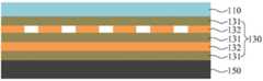
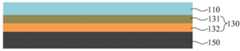
도 1은 본 발명의 일실시예에 따른 엘시디 기반의 디스플레이 패널을 사용하는 장치에서의 압력 감지 터치 시스템이 적용되는 터치스크린 패널의 구성을 도시한 도면이고, 도 2는 본 발명의 일실시예에 따른 엘시디 기반의 디스플레이 패널을 사용하는 장치에서의 압력 감지 터치 시스템이 적용되는 터치스크린 패널의 다른 일례의 구성을 도시한 도면이며, 도 3은 본 발명의 일실시예에 따른 엘시디 기반의 디스플레이 패널을 사용하는 장치에서의 압력 감지 터치 시스템이 LCD 디스플레이 패널의 내부 백라이트 유닛에 적용되는 구성을 도시한 도면이고, 도 4는 본 발명의 일실시예에 따른 엘시디 기반의 디스플레이 패널을 사용하는 장치에서의 압력 감지 터치 시스템에 적용된 가압 센싱 검출부의 배치 평면 구성을 도시한 도면이다. 도 1 내지 도 4에 각각 도시된 바와 같이, 본 발명의 일실시예에 따른 엘시디 기반의 디스플레이 패널을 사용하는 장치에서의 압력 감지 터치 시스템은, 터치스크린 패널(100), 및 가압 센싱 검출부(200)를 포함하여 구성될 수 있다.
FIG. 1 is a block diagram of a touch screen panel to which a pressure sensing touch system in an apparatus using a LCD-based display panel according to an embodiment of the present invention is applied. FIG. 3 is a diagram illustrating a configuration of another example of a touch screen panel to which a pressure-sensitive touch system in an apparatus using an LCD-based display panel according to an embodiment of the present invention is applied. FIG. 4 is a view showing a configuration in which a pressure-sensitive touch system in an apparatus to be used is applied to an internal backlight unit of an LCD display panel, and FIG. 4 is a cross- FIG. 2 is a diagram showing a layout plane configuration of a pressure sensing detector applied to the sensing touch system. FIG. 1 to 4, a pressure sensing touch system in an apparatus using a LCD-based display panel according to an embodiment of the present invention includes a
터치스크린 패널(100)은, 커버 윈도우(110)와, 센서 레이어(130) 및 LCD 디스플레이 패널(150)을 포함하는 구성이다. 이러한 터치스크린 패널(100)은 도 1에 도시된 바와 같이, 커버 윈도우(110)의 하부로 센서 레이어(130)가 배치되고, 센서 레이어(130)의 하부로 LCD 디스플레이 패널(150)이 순차로 배치되도록 구성될 수 있다. 또한, 터치스크린 패널(100)은 도 2에 도시된 바와 같이, 커버 윈도우(110)의 하부에 일체화로 구성된 센서 레이어(130)와 LCD 디스플레이 패널(150)이 배치되도록 구성할 수 있다. 여기서, 커버 윈도우(110)는 터치스크린 패널(100)의 센서 레이어(130)를 보호하며, 사용자의 터치 입력을 위한 창으로 사용된다. 또한, 센서 레이어(130)는 복수의 스캔 전극(Tx)과 복수의 수신 전극(Rx)의 조합으로 교차하는 복수의 노드를 통해 채널을 형성하는 터치 센서가 배치되는 구성이다. 또한, LCD 디스플레이 패널(150)은 터치스크린이 사용되는 스마트 기기의 표시 화면을 제공한다. 이러한 터치스크린 패널(100)에 구비되는 커버 윈도우(110)와 센서 레이어(130), 및 LCD 디스플레이 패널(150)은 스마트 기기에 일반적으로 적용되는 구성에 해당하므로 상세한 설명은 생략하기로 한다.
The
도 3에 도시된 바와 같이, LCD 디스플레이 패널(150)은 상부 글라스(Upper Glass)(151)의 하부로 LCD 패널(152)이 배치되고, LCD 패널(152)의 하부로 디퓨저 & 프리즘(Diffusers & Prisms)(153)과 도광 판(Light Guide Plate)(154) 및 반사체(Reflector)(155)와 램프(Lamp)(156)를 구비하는 백라이트 유닛(Back Light Unit, BLU)(157)이 배치되며, 백라이트 유닛(157)의 하부로 바닥 커버(Bottom Cover)(158)가 배치되는 구조로 구성될 수 있다. 여기서, 바닥 커버(158)는 도전성을 가진 도체로서, 가압 시 압력 감지 센서 층(201)과 정전용량 변화를 일으키는 전극 역할을 한다. 한편, 터치스크린 패널(100)은 디스플레이 패널 타입을 LCD를 사용하는 전면 적층(Full-Lamination) 구조와, 싱글 레이어 온 셀(SLOC) 구조 및 인 셀(In-cell) 구조 중 어느 하나로 구성될 수 있으며, 구체적인 터치스크린 패널(100)의 구조에 대해서는 후술하게 될 도 5 내지 도 7을 참조하여 설명하기로 한다.
3, the
가압 센싱 검출부(200)는, 터치스크린 패널(100)에 구비되는 LCD 디스플레이 패널(150)의 내부 하단부인 백라이트 유닛(BLU)(157)과 바닥 커버(Bottom Cover)(158) 사이에 배치되어, 커버 윈도우(110)에 가압되는 압력에 의해 에어 갭(203) 부분의 휘어짐으로 인한 압력 감지 센서 층(201)과 바닥 커버(158) 사이 거리 및 닿는 면적 변화에 따른 정전용량의 변화로 가압 터치를 검출하는 구성이다. 이러한 가압 센싱 검출부(200)는 도 1 및 도 2에 도시된 바와 같이, 커버 윈도우(110)와 LCD 디스플레이 패널(150) 사이에 존재하는 센서 레이어(130)들이 에어 갭(Air gap) 없이 LCD 디스플레이 패널(150)과 직접적으로 압착되어 합지되어 있다. 이로 인해 실제 커버 윈도우(110)를 가압하더라도 센서 레이어(130)의 터치 센서에 직접적인 정전용량을 변화시켜서 감도 변화를 야기 시킬 수 있는 구조적 제한이 존재하게 되므로, 커버 윈도우(110)를 가압 했을 때 가압 터치를 효과적이고 확실하게 검출할 수 있도록 가압 센싱 검출부(200)를 가압 시 가장 휘어짐이 많이 발생하는 LCD 디스플레이 패널(150)의 내부 백라이트 유닛(157)과 바닥 커버(158) 사이에 위치시켜 배치한다. 즉, LCD 디스플레이 패널(150)의 상부 부분은 에어 갭이 존재하지 않아 가압 시 휘어짐이 거의 없다.
The pressure
즉, 가압 센싱 검출부(200)는, 도 3에 도시된 바와 같이, LCD 디스플레이 패널(150)의 내부 하단부인 백라이트 유닛(157)에 배치되어 부착되는 압력 감지 센서 층(Force Detect Sensor Layer)(201)과, 압력 감지 센서 층(201)과 LCD 디스플레이 패널(150)의 바닥 커버(158) 사이에 가압을 하지 않았을 때 일정한 에어 갭(203)을 유지할 수 있도록 배치되어 부착되는 에어 갭 유지 물질 층(202), 및 에어 갭 유지 물질 층(202)을 통해 압력 감지 센서 층(201)과 바닥 커버(158) 사이에 형성되는 에어 갭(203)을 포함하여 구성될 수 있다. 이러한 가압 센싱 검출부(200)는 도 4에 도시된 바와 같이, 압력 감지 센서 층(201)은 다수의 압력 감지 검출(Multi Force Detecting)을 하기 위해 센서 개수는 가변적이고, 압력 감지 센서 층(201)의 센서 배치 구조에 대응하여 에어 갭 유지 물질 층(202)의 배치 모양이 바뀌도록 구성될 수 있다. 즉, 압력 감지 센서 층(201)의 센서 개수에 따라 몇 개의 압력 감지(Multi Force Detecting)를 검출할 지를 설정할 수 있다. 예를 들어, 압력 감지 센서가 두 개이면 두 개의 압력에 대한 압력 감지가 가능하고 압력 감지 센서의 개수를 늘릴수록 센서의 개수에 맞게 다수의 압력 감지가 가능하게 된다. 여기서, 에어 갭 유지 물질 층(202)은 가압되는 압력에 의해 휘어짐이 발생되어 압력 감지 센서 층(201)과 도전성 재질의 바닥 커버(158) 사이의 거리가 가변될 수 있는 겔 타입의 점착제(Adhesive)로 구성될 수 있다.
3, the pressure
가압 센싱 검출부(200)는, 커버 윈도우(110)를 가압 했을 때 에어 갭(203)이 존재하는 LCD 디스플레이 패널(150)의 하단부인 백라이트 유닛(157)과 바닥 커버(158) 사이가 휘어짐에 의하여 압력 감지 센서 층(201)과 도전성을 가진 LCD 디스플레이 패널(150)의 바닥 커버(158) 사이의 거리 및 닿는 면적 변화에 따른 직접적인 정전용량을 변화시켜서 터치 감도 변화를 검출하여 가압하는 압력의 세기 및 위치 변화를 알 수 있도록 동작하게 된다.
The pressure
도 5는 본 발명의 일실시예에 따른 엘시디 기반의 디스플레이 패널을 사용하는 장치에서의 압력 감지 터치 시스템이 적용될 수 있는 디스플레이 패널 타입을 LCD를 사용하는 전면 적층(Full-Lamination) 구조의 구성을 도시한 도면이고, 도 6은 본 발명의 일실시예에 따른 엘시디 기반의 디스플레이 패널을 사용하는 장치에서의 압력 감지 터치 시스템이 적용될 수 있는 싱글 레이어 온 셀(SLOC) 구조의 구성을 도시한 도면이며, 도 7은 본 발명의 일실시예에 따른 엘시디 기반의 디스플레이 패널을 사용하는 장치에서의 압력 감지 터치 시스템이 적용될 수 있는 인 셀(In-cell) 구조의 구성을 도시한 도면이다. 도 5는 커버 윈도우(110)의 하부로 점착제(131)가 배치 부착되고, 점착제(131)의 하부에 첫 번째 ITO 터치 센서 레이어(132)가 배치 부착되며, 첫 번째 ITO 터치 센서 레이어(132)의 하부로 점착제(131)를 매개로 하는 두 번째 ITO 터치 센서 레이어(132)가 배치 부착되고, 두 번째 ITO 터치 센서 레이어(132)의 하부에 점착제(131)를 매개로 가압 센싱 검출부(200)를 포함하는 LCD 디스플레이 패널(150)이 배치되는 구조로 구성된다. 도 6은 커버 윈도우(110)의 하부로 점착제(131)를 매개로 하나의 ITO 터치 센서 레이어(132)가 배치되고, 그 ITO 터치 센서 레이어(132)의 하부에 본 발명의 가압 센싱 검출부(200)를 포함하는 LCD 디스플레이 패널(150)이 배치되는 구조로 구성된다. 도 7은 커버 윈도우(110)의 하부로 점착제(131)를 매개로 컬러 필터 글라스(133)와 리퀴드 크리스탈(Liquid Crystal, LC)(134)과, ITO 터치 센서 레이어(132)와, 인슐레이터 레이어(135)와 브리지(136) 및 TFT 백플레인(137)이 배치되는 구조로 구성된다. 도 7의 붉은 색의 점선은 LCD 디스플레이 패널의 구성을 의미한다. 도 5 내지 도 7에 도시된 각각의 터치스크린 패널(100)의 구조는 통상적으로 사용되는 구조에 해당하므로 각각의 배치되는 구성의 설명은 생략하기로 하며, 다만 본 발명의 가압 센싱 검출부(200)가 LCD 디스플레이 패널(150)의 내부에 배치 구성됨을 특징으로 하고 있다.
FIG. 5 is a diagram illustrating a structure of a full-lamination structure using a LCD as a display panel type to which a pressure-sensitive touch system in an apparatus using a LCD-based display panel according to an embodiment of the present invention can be applied. FIG. 6 is a view illustrating a structure of a single layer on cell (SLOC) structure to which a pressure sensing touch system in an apparatus using a LCD-based display panel according to an embodiment of the present invention can be applied, 7 is a diagram illustrating a configuration of an in-cell structure to which a pressure sensing touch system in an apparatus using an LCD-based display panel according to an embodiment of the present invention can be applied. 5 shows a state in which a pressure
상술한 바와 같이, 본 발명의 일실시예에 따른 엘시디 기반의 디스플레이 패널을 사용하는 장치에서의 압력 감지 터치 시스템에 따르면, 통상의 터치스크린 패널에 적용되는 LCD 디스플레이 패널과 커버 윈도우 사이에 에어 갭이 존재하지 않아 커버 윈도우를 가압하더라도 터치 센서에 직접적인 정전용량을 변화시켜서 감도 변화를 야기 시킬 수 있는 구조적 제한이 존재하는 문제를 해소할 수 있도록 LCD 디스플레이 패널의 내부 하단부에 압력 감지 센서 층과 에어 갭을 형성하는 가압 센싱 검출부를 구성하여, 가압 시 에어 갭 부분의 휘어짐으로 인한 압력 감지 센서 층과 바닥 커버 사이 거리 및 닿는 면적 변화에 따른 정전용량의 변화로 가압 터치를 검출할 수 있도록 할 수 있다. 이러한 본 발명에 따른 엘시디 기반의 디스플레이 패널을 사용하는 장치에서의 압력 감지 터치 시스템은 기존 투과율에 아무런 영향을 주지 않으며, ITO와 같이 투명한 재질의 도전성 물질을 사용하지 않아도 되기 때문에 재료 선택의 폭이 넓으며, 일정한 도전성을 가진 값싼 재료를 사용하여 압력 감지 센서 층을 만들 수 있어 비용이 절감되며, 부도체/도체 모두 가압 시 가압 검출에 사용이 가능하고, 가압 검출용 압력 감지 센서 층을 센서 레이어와 분리하여 따로 사용하므로 기존의 터치 성능에는 영향이 발생되지 않도록 할 수 있다.
As described above, according to the pressure-sensitive touch system in the device using the LCD-based display panel according to an embodiment of the present invention, an air gap is formed between the LCD display panel and the cover window applied to a conventional touch screen panel The pressure sensor layer and the air gap are formed at the inner bottom of the LCD display panel so as to solve the problem that there is a structural limitation that can cause the sensitivity change by changing the capacitance directly to the touch sensor even when the cover window is pressed. The pressure sensing sensing portion can be configured to detect the pressure touch by a change in capacitance due to a distance between the pressure sensing layer and the bottom cover due to warping of the air gap portion during pressing and a contact area change. The pressure sensitive touch system in the device using the LCD-based display panel according to the present invention has no influence on the existing transmittance and does not need to use a transparent conductive material such as ITO, The pressure sensor layer can be formed using cheap materials with constant conductivity, and it is possible to reduce the cost. It is possible to use it for pressure detection when both insulators / conductors are pressurized, and separates the pressure sensor layer for pressure detection from the sensor layer Therefore, it is possible to prevent the influence on the existing touch performance.
이상 설명한 본 발명은 본 발명이 속한 기술분야에서 통상의 지식을 가진 자에 의하여 다양한 변형이나 응용이 가능하며, 본 발명에 따른 기술적 사상의 범위는 아래의 특허청구범위에 의하여 정해져야 할 것이다.The present invention may be embodied in many other specific forms without departing from the spirit or essential characteristics of the invention.
100: 터치스크린 패널110: 커버 윈도우
130: 센서 레이어131: 점착제
132: ITO 터치 센서 레이어133: 컬러 필터 글라스
134: 리퀴드 크리스탈(LC)135: 인슐레이터 레이어
136: 브리지137: TFT 백플레인
150: LCD 디스플레이 패널151: 상부 글라스
152: LCD 패널153: 디퓨저 & 프리즘
154: 도광 판155: 반사체
156: 램프157: 백라이트 유닛
158: 바닥 커버200: 가압 센싱 검출부
201: 압력 감지 센서 층202: 에어 갭 유지 물질 층
203: 에어 갭100: touch screen panel 110: cover window
130: Sensor layer 131: Pressure sensitive adhesive
132: ITO touch sensor layer 133: color filter glass
134: Liquid crystal (LC) 135: Insulator layer
136: Bridge 137: TFT backplane
150: LCD display panel 151: upper glass
152: LCD panel 153: diffuser & prism
154: light guide plate 155: reflector
156: Lamp 157: Backlight unit
158: bottom cover 200: pressure sensing detector
201: pressure sensing sensor layer 202: air gap holding material layer
203: air gap
Claims (7)
Translated fromKorean커버 윈도우(110)와, 센서 레이어(130) 및 LCD 디스플레이 패널(150)을 포함하는 터치스크린 패널(100); 및
상기 터치스크린 패널(100)에 구비되는 상기 LCD 디스플레이 패널(150)의 내부 하단부인 백라이트 유닛(BLU)(157)과 바닥 커버(Bottom Cover)(158) 사이에 배치되어, 상기 커버 윈도우(110)에 가압되는 압력에 의해 에어 갭(203) 부분의 휘어짐으로 인한 압력 감지 센서 층(201)과 바닥 커버(158) 사이의 거리 및 닿는 면적 변화에 따른 정전용량의 변화로 가압 터치를 검출하는 가압 센싱 검출부(200)를 포함하되,
상기 LCD 디스플레이 패널(150)은,
상부 글라스(Upper Glass)(151)의 하부로 LCD 패널(152)이 배치되고, 상기 LCD 패널(152)의 하부로 디퓨저 & 프리즘(Diffusers & Prisms)(153)과 도광 판(Light Guide Plate)(154) 및 반사체(Reflector)(155)와 램프(Lamp)(156)를 구비하는 백라이트 유닛(Back Light Unit, BLU)(157)이 배치되며, 상기 백라이트 유닛(157)의 하부로 바닥 커버(Bottom Cover)(158)가 배치되는 구조이며,
상기 가압 센싱 검출부(200)는,
상기 LCD 디스플레이 패널(150)의 내부 하단부인 백라이트 유닛(157)에 배치되어 부착되는 압력 감지 센서 층(Force Detect Sensor Layer)(201);
상기 압력 감지 센서 층(201)과 상기 LCD 디스플레이 패널(150)의 바닥 커버(158) 사이에 가압을 하지 않았을 때 일정한 에어 갭(203)을 유지할 수 있도록 배치되어 부착되는 에어 갭 유지 물질 층(202); 및
상기 에어 갭 유지 물질 층(202)을 통해 상기 압력 감지 센서 층(201)과 바닥 커버(158) 사이에 형성되는 에어 갭(203)을 포함하여 구성하는 것을 특징으로 하는, 엘시디 기반의 디스플레이 패널을 사용하는 장치에서의 압력 감지 터치 시스템.
A pressure-sensitive touch system in a device using an LCD-based display panel,
A touch screen panel 100 including a cover window 110, a sensor layer 130 and an LCD display panel 150; And
The cover window 110 is disposed between a backlight unit (BLU) 157 and a bottom cover 158 that is an internal lower end portion of the LCD display panel 150 provided in the touch screen panel 100, The pressure sensing layer 201 and the bottom cover 158 due to the bending of the air gap 203 due to the pressure applied to the pressure sensor layer 201 and the bottom cover 158, And a detection unit (200)
The LCD display panel 150 includes:
An LCD panel 152 is disposed below the upper glass 151 and a diffuser and prism 153 and a light guide plate 153 are disposed below the LCD panel 152 And a backlight unit (BLU) 157 having a reflector 155 and a lamp 156 are disposed on the backlight unit 157. A bottom cover Cover 158 is disposed,
The pressure sensing detection unit (200)
A force detection sensor layer 201 disposed on and attached to a backlight unit 157 which is an inner lower end of the LCD display panel 150;
An air gap-holding material layer 202 (not shown) disposed and attached so as to maintain a constant air gap 203 when no pressure is applied between the pressure sensing sensor layer 201 and the bottom cover 158 of the LCD display panel 150, ); And
And an air gap (203) formed between the pressure sensing layer (201) and the bottom cover (158) through the air gap holding material layer (202) Pressure sensitive touch system in the device used.
상기 커버 윈도우(110)의 하부로 센서 레이어(130)가 배치되고, 상기 센서 레이어(130)의 하부로 상기 LCD 디스플레이 패널(150)이 순차로 배치되거나,
상기 커버 윈도우(110)의 하부에 일체화로 구성된 센서 레이어(130)와 LCD 디스플레이 패널(150)이 배치되는 것을 특징으로 하는, 엘시디 기반의 디스플레이 패널을 사용하는 장치에서의 압력 감지 터치 시스템.
The touch screen panel (100) according to claim 1, wherein the touch screen panel (100)
A sensor layer 130 is disposed below the cover window 110 and the LCD display panel 150 is disposed sequentially below the sensor layer 130,
Wherein the sensor layer (130) and the LCD display panel (150) are disposed under the cover window (110).
디스플레이 패널 타입을 LCD를 사용하는 전면 적층(Full-Lamination) 구조와, 싱글 레이어 온 셀(SLOC) 구조 및 인 셀(In-cell) 구조 중 어느 하나로 구성하는 것을 특징으로 하는, 엘시디 기반의 디스플레이 패널을 사용하는 장치에서의 압력 감지 터치 시스템.
The touch screen panel (100) according to claim 1, wherein the touch screen panel (100)
The display panel type display device according to claim 1, wherein the display panel type is configured by a full-lamination structure using an LCD, a single-layer on-cell (SLOC) structure, and an in- Pressure sensitive touch system.
상기 압력 감지 센서 층(201)은 다수의 압력 감지 검출(Multi Force Detecting)을 하기 위해 센서 개수는 가변적이고, 상기 압력 감지 센서 층(201)의 센서 배치 구조에 대응하여 상기 에어 갭 유지 물질 층(202)의 배치 모양이 바뀌도록 구성하는 것을 특징으로 하는, 엘시디 기반의 디스플레이 패널을 사용하는 장치에서의 압력 감지 터치 시스템.
The apparatus of claim 1, wherein the pressure sensing detector (200)
The pressure sensing sensor layer 201 may include a plurality of sensors for varying the number of sensors to perform multi-force sensing, and may include a plurality of air gap holding material layers 202) is arranged to change the arrangement shape of the touch panel (200).
도전성을 가진 도체로서, 가압 시 압력 감지 센서 층(201)과 정전용량 변화를 일으키는 전극 역할을 하는 것을 특징으로 하는, 엘시디 기반의 디스플레이 패널을 사용하는 장치에서의 압력 감지 터치 시스템.The floor cover (158) according to claim 1, wherein the bottom cover (158)
A pressure sensitive touch system in an apparatus using a display panel based on a liquid crystal display, the conductive substrate having a conductive property and acting as an electrode for causing a change in capacitance with the pressure sensing layer (201) upon pressure.
Priority Applications (1)
| Application Number | Priority Date | Filing Date | Title |
|---|---|---|---|
| KR1020150081245AKR101684848B1 (en) | 2015-06-09 | 2015-06-09 | A pressure sensing touch system on the device using display panel of based on liquid crystal display |
Applications Claiming Priority (1)
| Application Number | Priority Date | Filing Date | Title |
|---|---|---|---|
| KR1020150081245AKR101684848B1 (en) | 2015-06-09 | 2015-06-09 | A pressure sensing touch system on the device using display panel of based on liquid crystal display |
Publications (1)
| Publication Number | Publication Date |
|---|---|
| KR101684848B1true KR101684848B1 (en) | 2016-12-12 |
Family
ID=57574195
Family Applications (1)
| Application Number | Title | Priority Date | Filing Date |
|---|---|---|---|
| KR1020150081245AActiveKR101684848B1 (en) | 2015-06-09 | 2015-06-09 | A pressure sensing touch system on the device using display panel of based on liquid crystal display |
Country Status (1)
| Country | Link |
|---|---|
| KR (1) | KR101684848B1 (en) |
Cited By (1)
| Publication number | Priority date | Publication date | Assignee | Title |
|---|---|---|---|---|
| KR20180076018A (en)* | 2016-12-27 | 2018-07-05 | 엘지디스플레이 주식회사 | touch type display device |
Citations (3)
| Publication number | Priority date | Publication date | Assignee | Title |
|---|---|---|---|---|
| KR20030059420A (en)* | 2001-12-29 | 2003-07-10 | 한국과학기술연구원 | 3D MEMS light collection plate, manufacturing method and display devices |
| KR20100031242A (en)* | 2008-09-12 | 2010-03-22 | 엘지디스플레이 주식회사 | Liquid crystal display device embedded touch panel therein |
| KR101452302B1 (en)* | 2013-07-29 | 2014-10-22 | 주식회사 하이딥 | Touch sensor panel |
- 2015
- 2015-06-09KRKR1020150081245Apatent/KR101684848B1/enactiveActive
Patent Citations (3)
| Publication number | Priority date | Publication date | Assignee | Title |
|---|---|---|---|---|
| KR20030059420A (en)* | 2001-12-29 | 2003-07-10 | 한국과학기술연구원 | 3D MEMS light collection plate, manufacturing method and display devices |
| KR20100031242A (en)* | 2008-09-12 | 2010-03-22 | 엘지디스플레이 주식회사 | Liquid crystal display device embedded touch panel therein |
| KR101452302B1 (en)* | 2013-07-29 | 2014-10-22 | 주식회사 하이딥 | Touch sensor panel |
Cited By (2)
| Publication number | Priority date | Publication date | Assignee | Title |
|---|---|---|---|---|
| KR20180076018A (en)* | 2016-12-27 | 2018-07-05 | 엘지디스플레이 주식회사 | touch type display device |
| KR102646220B1 (en)* | 2016-12-27 | 2024-03-08 | 엘지디스플레이 주식회사 | touch type display device |
Similar Documents
| Publication | Publication Date | Title |
|---|---|---|
| CN106104441B (en) | Touch sensor, touch detecting apparatus and detection method, touch control device | |
| US9864458B2 (en) | Touch-control display panel | |
| US10996498B2 (en) | Display apparatus with touch sensing and force sensing functions | |
| KR102240828B1 (en) | Touch panel and apparatus for driving thereof | |
| US9104283B2 (en) | Capacitive detection device with arrangement of linking tracks, and method implementing such a device | |
| JP4929319B2 (en) | Capacitive touch screen or touchpad for fingers or stylus | |
| KR102228561B1 (en) | Display device indlucing touch sensor | |
| US8531431B2 (en) | High speed 3D multi touch sensitive device | |
| CN103488361B (en) | Embedded touch display panel system for increasing touch position accuracy | |
| CN109074192B (en) | Pressure Sensing Display | |
| JP6677545B2 (en) | Display device | |
| CN106249953B (en) | A kind of pressure sensitivity touch screen and display device | |
| US10802640B2 (en) | Touch display device | |
| CN106855764B (en) | Touch display device | |
| WO2012173305A1 (en) | Hybrid touch panel capable of sensing capacitance and pressure | |
| CN106293241B (en) | A kind of pressure sensor and display device | |
| JPH1097382A (en) | Terminal device with touch screen and touch screen | |
| KR20160145236A (en) | A pressure sensing touch system on the device using display panel of based on organic light emitting diodes | |
| CN106446871A (en) | Touch device and touch method | |
| KR20100019810A (en) | Touch screen system | |
| CN106557193A (en) | Touch display unit | |
| US20170220168A1 (en) | Touch Substrate, Touch Display Panel and Display Device | |
| KR101684848B1 (en) | A pressure sensing touch system on the device using display panel of based on liquid crystal display | |
| KR101659281B1 (en) | A pressure sensing device for increasing the accuracy of pressure location by using assigned channel of display area on the 2-layer structure touch screen panel | |
| KR20180031863A (en) | Driving circuit, touch display device and method for driving thereof |
Legal Events
| Date | Code | Title | Description |
|---|---|---|---|
| PA0109 | Patent application | Patent event code:PA01091R01D Comment text:Patent Application Patent event date:20150609 | |
| PA0201 | Request for examination | ||
| PE0902 | Notice of grounds for rejection | Comment text:Notification of reason for refusal Patent event date:20160510 Patent event code:PE09021S01D | |
| E701 | Decision to grant or registration of patent right | ||
| PE0701 | Decision of registration | Patent event code:PE07011S01D Comment text:Decision to Grant Registration Patent event date:20161125 | |
| GRNT | Written decision to grant | ||
| PR0701 | Registration of establishment | Comment text:Registration of Establishment Patent event date:20161205 Patent event code:PR07011E01D | |
| PR1002 | Payment of registration fee | Payment date:20161205 End annual number:3 Start annual number:1 | |
| PG1601 | Publication of registration | ||
| FPAY | Annual fee payment | Payment date:20191212 Year of fee payment:4 | |
| PR1001 | Payment of annual fee | Payment date:20191212 Start annual number:4 End annual number:4 | |
| PR1001 | Payment of annual fee | Payment date:20201218 Start annual number:5 End annual number:5 | |
| PR1001 | Payment of annual fee | Payment date:20211202 Start annual number:6 End annual number:6 | |
| PR1001 | Payment of annual fee | Payment date:20221129 Start annual number:7 End annual number:7 | |
| PR1001 | Payment of annual fee | Payment date:20231205 Start annual number:8 End annual number:8 | |
| PR1001 | Payment of annual fee | Payment date:20241119 Start annual number:9 End annual number:9 |