KR101684796B1 - Suction unit - Google Patents
Suction unitDownload PDFInfo
- Publication number
- KR101684796B1 KR101684796B1KR1020150115957AKR20150115957AKR101684796B1KR 101684796 B1KR101684796 B1KR 101684796B1KR 1020150115957 AKR1020150115957 AKR 1020150115957AKR 20150115957 AKR20150115957 AKR 20150115957AKR 101684796 B1KR101684796 B1KR 101684796B1
- Authority
- KR
- South Korea
- Prior art keywords
- noise reduction
- chamber
- noise
- reduction unit
- motor
- Prior art date
- Legal status (The legal status is an assumption and is not a legal conclusion. Google has not performed a legal analysis and makes no representation as to the accuracy of the status listed.)
- Active
Links
- 230000009467reductionEffects0.000claimsabstractdescription115
- 238000000034methodMethods0.000claimsdescription13
- 238000011144upstream manufacturingMethods0.000claimsdescription5
- 239000000470constituentSubstances0.000description5
- 230000008569processEffects0.000description3
- 230000008901benefitEffects0.000description2
- 238000002679ablationMethods0.000description1
- 230000008033biological extinctionEffects0.000description1
- 230000002542deteriorative effectEffects0.000description1
- 239000000428dustSubstances0.000description1
- 238000012986modificationMethods0.000description1
- 230000004048modificationEffects0.000description1
- 230000000644propagated effectEffects0.000description1
Images


Classifications
- G—PHYSICS
- G10—MUSICAL INSTRUMENTS; ACOUSTICS
- G10K—SOUND-PRODUCING DEVICES; METHODS OR DEVICES FOR PROTECTING AGAINST, OR FOR DAMPING, NOISE OR OTHER ACOUSTIC WAVES IN GENERAL; ACOUSTICS NOT OTHERWISE PROVIDED FOR
- G10K11/00—Methods or devices for transmitting, conducting or directing sound in general; Methods or devices for protecting against, or for damping, noise or other acoustic waves in general
- G10K11/16—Methods or devices for protecting against, or for damping, noise or other acoustic waves in general
- G10K11/161—Methods or devices for protecting against, or for damping, noise or other acoustic waves in general in systems with fluid flow
- A—HUMAN NECESSITIES
- A47—FURNITURE; DOMESTIC ARTICLES OR APPLIANCES; COFFEE MILLS; SPICE MILLS; SUCTION CLEANERS IN GENERAL
- A47L—DOMESTIC WASHING OR CLEANING; SUCTION CLEANERS IN GENERAL
- A47L9/00—Details or accessories of suction cleaners, e.g. mechanical means for controlling the suction or for effecting pulsating action; Storing devices specially adapted to suction cleaners or parts thereof; Carrying-vehicles specially adapted for suction cleaners
- A47L9/0081—Means for exhaust-air diffusion; Means for sound or vibration damping
- A—HUMAN NECESSITIES
- A47—FURNITURE; DOMESTIC ARTICLES OR APPLIANCES; COFFEE MILLS; SPICE MILLS; SUCTION CLEANERS IN GENERAL
- A47L—DOMESTIC WASHING OR CLEANING; SUCTION CLEANERS IN GENERAL
- A47L9/00—Details or accessories of suction cleaners, e.g. mechanical means for controlling the suction or for effecting pulsating action; Storing devices specially adapted to suction cleaners or parts thereof; Carrying-vehicles specially adapted for suction cleaners
- A47L9/22—Mountings for motor fan assemblies
- G—PHYSICS
- G10—MUSICAL INSTRUMENTS; ACOUSTICS
- G10K—SOUND-PRODUCING DEVICES; METHODS OR DEVICES FOR PROTECTING AGAINST, OR FOR DAMPING, NOISE OR OTHER ACOUSTIC WAVES IN GENERAL; ACOUSTICS NOT OTHERWISE PROVIDED FOR
- G10K11/00—Methods or devices for transmitting, conducting or directing sound in general; Methods or devices for protecting against, or for damping, noise or other acoustic waves in general
- G10K11/16—Methods or devices for protecting against, or for damping, noise or other acoustic waves in general
- G10K11/172—Methods or devices for protecting against, or for damping, noise or other acoustic waves in general using resonance effects
Landscapes
- Engineering & Computer Science (AREA)
- Mechanical Engineering (AREA)
- Physics & Mathematics (AREA)
- Acoustics & Sound (AREA)
- Multimedia (AREA)
- Aviation & Aerospace Engineering (AREA)
- Chemical & Material Sciences (AREA)
- Combustion & Propulsion (AREA)
- Fluid Mechanics (AREA)
- Motor Or Generator Frames (AREA)
- Electric Suction Cleaners (AREA)
- Air-Conditioning For Vehicles (AREA)
- Compressor (AREA)
Abstract
Translated fromKoreanDescription
Translated fromKorean본 발명은 흡입 유닛에 관한 것이다.The present invention relates to a suction unit.
흡입 유닛은 일반적으로 전기 청소기에 구비되어 먼지를 포함한 공기를 흡입하는데 사용될 수 있다.The suction unit is generally provided in an electric vacuum cleaner and can be used to suck air containing dust.
상기 흡입 유닛은 흡입 모터와 상기 흡입 모터를 수용하는 모터 챔버를 포함할 수 있다. 상기 흡입 모터가 작동하는 과정에서는 소음이 발생하는데, 이러한 소음을 저감시키기 위하여, 공명기를 사용할 수 있다.The suction unit may include a suction motor and a motor chamber for receiving the suction motor. In the process of operating the suction motor, noise is generated. To reduce such noise, a resonator may be used.
선행문헌인 한국등록특허공보 제10-0710232호(등록일 2007.04.16.)에는 진공청소기의 소음저감 장치가 개시된다.Korean Patent Registration No. 10-0710232 (registered on Apr. 16, 2007), which is a prior art document, discloses a noise reduction apparatus for a vacuum cleaner.
선행문헌의 소음저감 장치는, 모터챔버의 외측에 구비되는 공명기를 포함한다. 공명기는 상기 모터챔버의 외주면 외측에 형성된다.The noise reduction apparatus of the prior art includes a resonator provided outside the motor chamber. A resonator is formed outside the outer circumferential surface of the motor chamber.
그런데, 선행문헌에 의하면, 공명기가 특정 주파수를 가지는 소음을 줄일 수는 있으나, 모터챔버 외측에 구비되므로 흡입모터에 의해서 유동되는 공기가 일부가 공명기 측을 유동할 수 있으며, 공명기의 입구 측에서 소용돌이(vortex)가 발생하여 소용돌이에 의한 유동 소음이 증가되는 문제가 있다.However, according to the prior art, the resonator can reduce the noise having a specific frequency. However, since the resonator is provided outside the motor chamber, a part of air flowing by the suction motor can flow on the resonator side, (vortex) is generated to increase the flow noise due to the vortex.
본 발명의 목적은, 흡입 모터의 작동 시 발생되는 소음이 최소화되는 흡입 유닛을 제공하는 것에 있다.It is an object of the present invention to provide a suction unit in which noises generated during operation of the suction motor are minimized.
또한, 본 발명의 목적은, 흡입 모터의 상류 및 하류에 각각 저감 유닛을 장착함으로써, 사이즈를 증가시키거나 변경시키지 않고도 배출 소음을 저감시킬 수 있는 흡입 유닛을 제공하는 것에 있다.It is also an object of the present invention to provide a suction unit capable of reducing exhaust noise without increasing or changing the size by mounting a reduction unit upstream and downstream of the suction motor, respectively.
상기와 같은 목적을 달성하기 위하여, 본 발명의 흡입 유닛은, 공기 유동을 발생하기 위한 흡입 모터; 상기 흡입 모터를 감싸며, 상기 흡입 모터의 작동 시 발생되는 소음을 줄이기 위하여 공명기로 작용하는 소음 저감 유닛; 및 상기 소음 저감 유닛을 감싸는 모터 챔버를 포함하고, 상기 소음 저감 유닛은, 상기 흡입 모터에 의해서 유동되는 공기의 통로를 제공하는 공기 유로와, 하나 이상의 주파수 대역의 소음을 제거하기 위하여, 소음 저감 챔버와, 상기 소음 저감 챔버로 소음의 음파가 인입되도록 하는 연통 홀을 포함하고, 상기 공기 유로는 상기 소음 저감 챔버와 구획되어 공기가 상기 공기 유로를 통과하는 과정에서 소음의 음파는 상기 연통 홀을 통하여 소음 저감 챔버에 인입된다.In order to achieve the above object, a suction unit of the present invention includes: a suction motor for generating an air flow; A noise reduction unit that surrounds the suction motor and acts as a resonator to reduce noise generated during operation of the suction motor; And a motor chamber enclosing the noise reduction unit, wherein the noise reduction unit includes: an air flow path for providing a path of air to be flowed by the suction motor; and a noise reduction chamber And a communication hole through which the sound waves of noise are drawn into the noise reduction chamber, and the air flow path is divided by the noise reduction chamber so that the sound waves of noise are transmitted through the communication hole And enters the noise reduction chamber.
그리고, 상기 소음 저감 유닛을 모터 챔버가 둘러쌀 수 있다. 따라서, 소음 저감 유닛과 모터 챔버가 이중으로 소음을 차단하게 된다.Then, the noise reduction unit can be surrounded by the motor chamber. Therefore, the noise reduction unit and the motor chamber double block the noise.
상기 소음 저감 유닛이 흡입 모터를 감싼 상태에서 공기 유동이 가능하도록, 상기 소음 저감 유닛은, 상기 흡입 모터로 공기가 유동되도록 하기 위한 공기 유동부를 더 포함할 수 있다.The noise reduction unit may further include an air flow unit for allowing air to flow to the suction motor such that the noise reduction unit can flow air while the suction motor is wrapped around the suction motor.
상기 소음 저감 유닛이 다수의 주파수 대역의 소음을 저감시킬 수 있도록, 상기 소음 저감 유닛은, 상기 흡입 모터의 상류에 위치되는 제1저감 유닛과, 상기 흡입 모터의 하류에 위치되는 제2저감 유닛을 포함할 수 있다.The noise reduction unit includes a first reduction unit located upstream of the suction motor and a second reduction unit located downstream of the suction motor so that the noise reduction unit can reduce noise in a plurality of frequency bands .
이때, 상기 제1저감 유닛 및 제2저감 유닛 각각은, 다수의 연통홀과, 소음 저감 챔버를 포함하고, 상기 제1저감 유닛에서 제거될 수 있는 소음의 주파수가 상기 제2저감 유닛에서 제거될 수 있는 소음의 주파수와 다르도록, 상기 제1저감 유닛의 다수의 연통홀의 개수, 길이 또는 직경은 상기 제2저감 유닛의 다수의 연통홀의 개수, 길이 또는 직경과 다를 수 있다.In this case, each of the first reduction unit and the second reduction unit includes a plurality of communication holes and a noise reduction chamber, and the frequency of the noise that can be removed from the first reduction unit is removed from the second reduction unit Length, or diameter of the plurality of communication holes of the first abatement unit may be different from the number, length, or diameter of the plurality of communication holes of the second abatement unit such that the number, length, or diameter of the plurality of communication holes of the first abatement unit is different.
또는, 상기 제1저감 유닛의 소음 저감 챔버의 부피는 상기 제2저감 유닛의 소음 저감 챔버의 부피와 다를 수 있다.Alternatively, the volume of the noise reduction chamber of the first reduction unit may be different from the volume of the noise reduction chamber of the second reduction unit.
상기 소음 저감 유닛 자체가 공기의 소용돌이에 의한 유동 소음을 발생하는 것을 방지하기 위하여, 상기 소음 저감 유닛은 다수의 연통 홀을 포함하고, 상기 다수의 연통 홀이 하나의 소음 저감 챔버와 연통될 수 있다.In order to prevent the noise reduction unit itself from generating flow noise due to vortex of the air, the noise reduction unit may include a plurality of communication holes, and the communication holes may communicate with one noise reduction chamber .
이때, 상기 소음 저감 유닛은, 상기 흡입 모터의 일부를 둘러싸는 프레임과, 상기 프레임과 함께 공기를 상기 흡입 모터 측으로 안내하는 공기 안내부를 포함하고, 상기 공기 안내부와 상기 프레임이 상기 소음 저감 챔버를 형성하고, 상기 공기 안내부에 다수의 연통 홀이 형성될 수 있다.At this time, the noise reduction unit includes a frame surrounding a part of the suction motor, and an air guide portion for guiding air to the suction motor side together with the frame, wherein the air guide portion and the frame support the noise reduction chamber And a plurality of communication holes may be formed in the air guide portion.
그리고, 상기 프레임의 내부에 상기 공기 안내부가 위치되며, 상기 프레임의 내주면 일부와 상기 공기 안내부의 외주면이 상기 소음 저감 챔버를 형성할 수 있다.The air guide portion is located inside the frame, and a part of the inner circumferential surface of the frame and the outer circumferential surface of the air guide portion form the noise reducing chamber.
그리고, 상기 공기 안내부는, 축 방향을 공기가 유동하는 안내 바디를 포함하고, 상기 안내 바디의 원주 방향으로 다수의 연통 홀이 형성되어 배치될 수 있다.The air guide includes a guide body through which air flows in the axial direction, and a plurality of communication holes may be formed in a circumferential direction of the guide body.
또한, 상기 소음 저감 유닛은 상기 흡입 모터의 일부를 둘러싸는 모터 커버와, 상기 모터 커버의 외주면 일부를 둘러싸는 챔버 형성부를 포함하고, 상기 모터 커버에 다수의 연통 홀이 형성되고, 상기 모터 커버 및 상기 챔버 형성부가 상기 소음 저감 챔버를 형성할 수 있다.The noise reduction unit may include a motor cover surrounding a part of the suction motor, and a chamber forming part surrounding a part of an outer circumferential surface of the motor cover, wherein a plurality of communication holes are formed in the motor cover, The chamber forming portion may form the noise reducing chamber.
또한, 상기 소음 저감 유닛은 상기 흡입 모터의 일부를 둘러싸는 모터 커버와, 상기 모터 커버의 내측 단차부에 안착되는 챔버 형성벽을 포함하고, 상기 챔버 형성벽에 다수의 연통 홀이 형성되고, 상기 모터 커버 및 상기 챔버 형성벽이 상기 소음 저감 챔버를 형성할 수 있다.
The noise reduction unit may include a motor cover surrounding a part of the suction motor, and a chamber forming wall seated on an inner stepped portion of the motor cover, wherein a plurality of communication holes are formed in the chamber forming wall, The motor cover and the chamber forming wall can form the noise reduction chamber.
제안되는 발명에 의하면, 모터 챔버 내에 구비되는 소음 저감 유닛이 흡입 모터를 수용하므로, 소음 저감 유닛이 일차적으로 소음을 저감시킬 수 있을 뿐만 아니라 이차적으로 상기 모터 챔버가 소음을 저감시킬 수 있으므로, 상기 흡입 모터의 작동 시 발생되는 소음이 한층 더 줄어들 수 있는 장점이 있다.According to the proposed invention, since the noise reduction unit provided in the motor chamber accommodates the suction motor, not only the noise reduction unit can reduce the noise in the first place but also the noise can be reduced in the motor chamber secondarily, There is an advantage that the noise generated during the operation of the motor can be further reduced.
또한, 공기가 안내 바디를 유동하는 과정에서 안내 바디의 원주 방향으로 따라 다수의 연통 홀이 형성되므로, 연통 홀 주변에서의 소용돌이에 의한 공기의 유동 소음이 발생하는 것이 방지될 수 있다.In addition, since a plurality of communication holes are formed along the circumferential direction of the guide body in the course of air flowing through the guide body, it is possible to prevent air flow noise due to vortexes around the communication holes.
또한, 소음 저감 유닛이 직접 흡입 모터를 둘러싸므로, 특정 주파수 대역의 소음의 음파가 소음 저감 유닛으로 이동하는 거리가 줄어들고, 이에 따라 소음의 음파가 이동하는 과정에서 음파의 주파수 변동이 최소화되어 소음 저감 유닛의 성능이 저하되는 것이 방지되는 장점이 있다.Further, since the noise reduction unit directly surrounds the suction motor, the distance that the sound waves of the noise of the specific frequency band moves to the noise reduction unit is reduced, and accordingly, the frequency fluctuation of the sound waves is minimized in the process of moving the sound waves of the noise, There is an advantage that the performance of the unit is prevented from deteriorating.
또한, 본 발명의 경우, 모터 챔버 내에서 상기 흡입 모터의 상류 및 하류에 소음 저감 유닛이 배치됨에 따라서, 사이즈를 증가시키거나 변경하지 않고도 배출 소음을 줄일 수 있는 장점이 있다.
Further, in the case of the present invention, since the noise reduction unit is disposed in the motor chamber upstream and downstream of the suction motor, it is possible to reduce the exhaust noise without increasing or changing the size.
도 1은 본 발명의 일 실시 예에 따른 흡입 유닛의 분해 사시도.
도 2는 본 발명의 일 실시 예에 따른 흡입 유닛의 단면도.
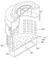
도 3은 본 발명의 일 실시 예에 따른 소음 저감 유닛의 분해 사시도.
도 4는 본 발명의 일 실시 예에 따른 소음 저감 유닛의 단면도.
도 5는 소음 저감 유닛의 존재 여부에 따른 주파수 별 소음을 보여주는 그래프.
도 6은 본 발명의 다른 실시 예에 따른 소음 저감 유닛의 단면도.1 is an exploded perspective view of a suction unit according to an embodiment of the present invention;
2 is a sectional view of a suction unit according to an embodiment of the present invention;
3 is an exploded perspective view of a noise reduction unit according to an embodiment of the present invention;
4 is a cross-sectional view of a noise reduction unit according to an embodiment of the present invention.
5 is a graph showing frequency-specific noises according to the presence or absence of a noise reduction unit.
6 is a sectional view of a noise reduction unit according to another embodiment of the present invention;
이하, 본 발명의 일부 실시 예들을 예시적인 도면을 통해 상세하게 설명한다. 각 도면의 구성요소들에 참조부호를 부가함에 있어서, 동일한 구성요소들에 대해서는 비록 다른 도면상에 표시되더라도 가능한 한 동일한 부호를 가지도록 하고 있음에 유의해야 한다. 또한, 본 발명의 실시 예를 설명함에 있어, 관련된 공지 구성 또는 기능에 대한 구체적인 설명이 본 발명의 실시예에 대한 이해를 방해한다고 판단되는 경우에는 그 상세한 설명은 생략한다.Hereinafter, some embodiments of the present invention will be described in detail with reference to exemplary drawings. It should be noted that, in adding reference numerals to the constituent elements of the drawings, the same constituent elements are denoted by the same reference symbols as possible even if they are shown in different drawings. In the following description of the embodiments of the present invention, a detailed description of known functions and configurations incorporated herein will be omitted when it may make the difference that the embodiments of the present invention are not conclusive.
또한, 본 발명의 실시예의 구성 요소를 설명하는 데 있어서, 제 1, 제 2, A, B, (a), (b) 등의 용어를 사용할 수 있다. 이러한 용어는 그 구성 요소를 다른 구성 요소와 구별하기 위한 것일 뿐, 그 용어에 의해 해당 구성 요소의 본질이나 차례 또는 순서 등이 한정되지 않는다. 어떤 구성 요소가 다른 구성요소에 "연결", "결합" 또는 "접속"된다고 기재된 경우, 그 구성 요소는 그 다른 구성요소에 직접적으로 연결되거나 접속될 수 있지만, 각 구성 요소 사이에 또 다른 구성 요소가 "연결", "결합" 또는 "접속"될 수도 있다고 이해되어야 할 것이다.In describing the components of the embodiment of the present invention, terms such as first, second, A, B, (a), and (b) may be used. These terms are intended to distinguish the constituent elements from other constituent elements, and the terms do not limit the nature, order or order of the constituent elements. When a component is described as being "connected", "coupled", or "connected" to another component, the component may be directly connected or connected to the other component, Quot; may be "connected," "coupled," or "connected. &Quot;
도 1은 본 발명의 일 실시 예에 따른 흡입 유닛의 분해 사시도이고, 도 2는 본 발명의 일 실시 예에 따른 흡입 유닛의 단면도이다.FIG. 1 is an exploded perspective view of a suction unit according to an embodiment of the present invention, and FIG. 2 is a sectional view of a suction unit according to an embodiment of the present invention.
도 3은 본 발명의 일 실시 예에 따른 소음 저감 유닛의 분해 사시도이고, 도 4는 본 발명의 일 실시 예에 따른 소음 저감 유닛의 단면도이다.FIG. 3 is an exploded perspective view of a noise reduction unit according to an embodiment of the present invention, and FIG. 4 is a sectional view of a noise reduction unit according to an embodiment of the present invention.
도 1 내지 도 4를 참조하면, 본 발명의 일 실시 예에 따른 흡입 유닛(1)은, 일 예로 진공 청소기의 내부에 장착되어 사용될 수 있다.1 to 4, the
상기 흡입 유닛(1)은, 흡입력을 발생하기 위한 흡입 모터(10)와, 상기 흡입 모터(10)를 수용하고 상기 흡입 모터(10)의 작동 시 발생되는 소음을 저감하기 위한 소음 저감 유닛(20)과, 상기 소음 저감 유닛(20)을 수용하는 모터 챔버(30)를 포함할 수 있다.The
상기 흡입 모터(10)는, 도시되지는 않았으나, 임펠러와, 상기 임펠러를 회전시키기 위한 구동부를 포함할 수 있으며, 본 실시 예에서는 공지의 구조에 의해서 구현될 수 있으므로 자세한 설명은 생락하기로 한다.Although not shown, the
상기 모터 챔버(30)는, 제1모터 챔버(31)와, 상기 제1모터 챔버(31)와 결합되는 제2모터 챔버(32)를 포함할 수 있다.The
상기 제2모터 챔버(32)에는 공기가 통과하는 입구(320)가 구비되고, 상기 제1모터 챔버(31)에는 상기 흡입 모터(10)를 지난 공기가 배출되는 출구(312)가 구비된다.The
상기 소음 저감 유닛(20)은, 제1저감 유닛(21)과, 상기 제1저감 유닛(21)과 결합되는 제2저감 유닛(25) 중 하나 이상을 포함할 수 있다.The
상기 제1저감 유닛(21)은 상기 흡입 모터(10)의 상류에 위치되고, 상기 제2저감 유닛(25)은 상기 흡입 모터(10)의 하류에 위치될 수 있다.The
그리고, 상기 소음 저감 유닛(20)은 상기 흡입 모터(10)를 감쌀 수 있다. 즉, 본 실시 예에서는 상기 모터 챔버(30) 내에 상기 소음 저감 유닛(20)이 배치되고, 상기 소음 저감 유닛(20) 내에 상기 흡입 모터(10)가 위치된다.The
따라서, 본 실시 예에 의하면, 상기 소음 저감 유닛(20)이 일차적으로 소음을 저감시킬 수 있을 뿐만 아니라 이차적으로 상기 모터 챔버(30)가 소음을 저감시킬 수 있으므로, 상기 흡입 모터(10)의 작동 시 발생되는 소음이 한층 더 줄어들 수 있는 장점이 있다.Therefore, according to the present embodiment, not only the
상기 소음 저감 유닛(20)은 특정 주파수 대역의 소음을 소멸시킴에 따라 소음을 저감시킬 뿐만 아니라, 상기 흡입 모터(10)를 차폐함으로써, 소음이 외부로 전파되는 것을 차단시키는 역할을 한다.The
상기 제1저감 유닛(21)은 일 예로 상기 제2저감 유닛(25)의 상측에 결합될 수 있다.The
이때, 상기 제2저감 유닛(25)이 생략되는 경우에는 상기 제1저감 유닛(21)은 상기 모터 챔버(30)에 결합될 수 있다. 또는 상기 제1저감 유닛(21)이 생략되는 경우에는 상기 제2저감 유닛(25)은 상기 모터 챔버(30)에 결합될 수 있다.At this time, when the
상기 제1저감 유닛(21)은, 상기 흡입 모터(10)의 일부를 둘러싸는 프레임을 포함할 수 있다. 상기 프레임은, 제한적이지는 않으나, 제1프레임(220)과, 상기 제1프레임(220)의 상측에 결합되는 제2프레임(230)을 포함할 수 있다.The
상기 제2프레임(230)에는 상기 흡입 모터(10)로 공기가 유동되도록 하기 위한 공기 유동부(232)가 구비될 수 있다. 상기 공기 유동부(232)는 상기 제1모터 챔버(32)의 개구(320)에 삽입될 수 있다.The
상기 제1프레임(220) 내에는 상기 공기 유동부(232)를 지난 공기를 상기 흡입 모터(10) 측으로 안내하기 위한 공기 안내부(210)가 구비될 수 있다.An
상기 공기 안내부(210)는 상기 제1프레임(220)의 내주면 직경 보다 작은 직경을 가지는 안내 바디(211)와, 상기 안내 바디(211)에서 반경 방향으로 연장되는 연장부(218)를 포함할 수 있다.The
상기 안내 바디(211)는 일 예로 원통 형상으로 형성될 수 있으며, 공기가 유동하기 위한 공기 유로(212)를 형성한다. 이때, 공기는 상기 안내 바디(211)의 축 방향으로 상기 공기 유로(212)를 유동한다.The
상기 연장부(218)는 상기 안내 바디(211)에서 반경 방향으로 연장되어 상기 제1프레임(220)의 내주면에 접촉할 수 있다.The
상기 안내 바디(211)에는 하나 이상의 제1연통 홀(214)이 형성될 수 있다. 도 4에는 다수의 제1연통 홀(214)이 상기 안내 바디(211)에 형성되는 것이 도시된다.At least one
그리고, 상기 안내 바디(211)의 외주면과 상기 제1프레임(220)의 내주면은 제1소음 저감 챔버(222)를 형성한다.The outer circumferential surface of the
본 실시 예에서 상기 안내 바디(211)에 형성되는 다수의 제1연통 홀(214)과 상기 제1소음 저감 챔버(222)가 제1공명기 역할을 한다. 이때, 하나의 제1소음 저감 챔버(222)가 상기 다수의 제1연통 홀(214)과 연통될 수 있다.In this embodiment, a plurality of first communication holes 214 formed in the
상기 다수의 제1연통 홀(214)은 소음의 음파가 상기 제1소음 저감 챔버(222)로 인입되도록 하는 입구 역할을 한다.The plurality of first communication holes 214 serve as an inlet for allowing sound waves of noise to enter the first
상세히, 상기 흡입 모터(10)를 공기가 유동하면서 발생되는 소음과 같이 상기 흡입 모터(10)의 작동 시 발생되는 소음의 특정 정상파는 상기 다수의 제1연통 홀(214)을 지나 상기 제1소음 저감 챔버(222)로 이동하게 된다. 그리고, 상기 제1소음 저감 챔버(222)로 이동된 특정 정상파는 역상(Out of phase) 형태의 진동으로 변한 후, 상기 연통 홀(214)을 통과하게 된다. 따라서, 상기 특정 정상파에 대한 위상 변위(Phase shifting)가 발생하여, 상기 흡입 유닛(1)에서 발생되는 특정 정상파가 소멸하게 되고, 이에 따라 소음이 저감될 수 있다.Specifically, a specific standing wave of noise generated during operation of the
이때, 공기가 상기 안내 바디(211)의 내부 공간을 유동하므로, 상기 연통 홀(214)에 의한 유동 소음이 발생되지 않도록, 다수의 연통 홀(214)은 상기 안내 바디(211)의 원주 방향으로 이격되어 배치될 수 있다.Since the air flows in the internal space of the
만약, 안내 바디(211)에 하나의 제1연통 홀이 형성되는 경우, 공기가 상기 안내 바디(211)를 통과하는 과정에서 상기 제1연통 홀 주변에서 상기 제1연통 홀에 의해서 소용돌이가 발생되고, 이에 따라 공기의 유동 소음이 발생되는 문제가 있을 수 있다.If one first communication hole is formed in the
그러나, 본 실시 예와 같이 상기 안내 바디(211)의 원주 방향으로 다수의 제1연통 홀(214)이 형성되고, 공기는 상기 안내 바디(211)의 축 방향으로 유동하는 경우, 공기가 다수의 제1연통 홀(214) 중 일부 제1연통 홀로 집중되는 것이 방지되고 이에 따라서 제1연통 홀 측에서 소용돌이가 발생하는 것이 방지된다. 따라서, 소용돌이에 의한 공기의 유동 소음이 발생하는 것이 방지될 수 있다.However, when a plurality of first communication holes 214 are formed in the circumferential direction of the
물론, 상기 다수의 제1연통 홀(214) 중 일부 제1연통 홀 들은 상기 안내 바디(211)의 축 방향으로 이격되어 배치될 수도 있다.Of course, some of the first communication holes 214 may be spaced apart from each other in the axial direction of the
다수의 제1연통 홀(214)의 개수와 다수의 제1연통 홀(214)의 직경 및 길이와 상기 제1소음 저감 챔버(222)의 부피를 조절하여 상기 흡입 유닛(1)에서 발생되는 특정 주파수 대역의 소음을 줄일 수 있다.The number of the first communication holes 214 and the diameter and length of the plurality of first communication holes 214 and the volume of the first
상기 제2프레임(220)의 외측에는 프레임 커버(240)가 구비될 수 있다. 상기 프레임 커버(240)는 상기 모터 챔버(30)에 체결될 수 있다.A
한편, 상기 제2저감 유닛(25)은, 상기 흡입 모터(10)를 커버하는 모터 커버(250)와, 상기 모터 커버(250)의 외측에 결합되는 챔버 형성부(260)를 더 포함할 수 있다.The
상기 모터 커버(250)는 일 예로 원통 형상으로 형성될 수 있으며, 둘레 방향으로 다수의 공기 홀(252)이 형성될 수 있다. 상기 공기 홀(252)은 공기가 유동하기 위한 공기 유로를 제공한다.The
상기 모터 커버(250)는, 제한적이지는 않으나, 상기 제2프레임(220)과 결합될 수 있다. 일 예로 상기 모터 커버(250)의 상측 일부가 상기 제2프레임(220)에 삽입된 상태에서 스크류에 의해서 상기 모터 커버(250) 및 상기 제2프레임(220)이 체결될 수 있다. 본 발명에서 상기 모터 커버(250)와 상기 제2프레임(220)의 체결 방법에는 제한이 없음을 밝혀둔다.The
상기 모터 커버(250)의 바닥벽(251)에는 하나 이상의 제2연통 홀이 형성될 수 있다. 도 4에는 일 예로 바닥벽(251)에 다수의 제2연통 홀(254)이 형성되는 것이 도시된다.At least one second communication hole may be formed in the
상기 챔버 형성부(260)는 상기 모터 커버(250)의 외측에서 상기 바닥벽(251)에 결합되어 상기 바닥벽(251)과 함께 제1소음 저감 챔버(262)를 형성할 수 있다.The
즉, 본 실시 예에서 상기 다수의 제2연통 홀(254)과 상기 제2소음 저감 챔버(262)는 제2공명기 역할을 한다. 이때, 하나의 제2소음 저감 챔버(260)가 상기 다수의 제2연통 홀(254)과 연통될 수 있다.That is, in the present embodiment, the plurality of second communication holes 254 and the second
다수의 제2연통 홀(254)의 개수와 다수의 제2연통 홀(254)의 직경 및 길이와 상기 제2소음 저감 챔버(262)의 부피를 조절하여 상기 흡입 유닛(1)에서 발생되는 특정 주파수 대역의 소음을 줄일 수 있다.The number of the second communication holes 254, the diameter and length of the plurality of second communication holes 254, and the volume of the second
이때, 제1공명기와 제2공명기는 서로 다른 고유 주파수를 가지도록 설계될 수 있다.At this time, the first resonator and the second resonator may be designed to have different natural frequencies.
예를 들어, 제1공명기의 유입홀의 개수나 유입홀의 직경 또는 길이를 상기 제2공명기의 유입홀의 개수나 유입홀의 직경 또는 길이와 다르게 설계할 수 있다.For example, the number of the inflow holes of the first resonator, the diameter or length of the inflow hole may be designed differently from the number of the inflow holes of the second resonator, or the diameter or length of the inflow hole.
또는 제1공명기의 소음 저감 챔버의 부피를 상기 제2공명기의 소음 저감 챔버의 부피와 다르게 설계할 수 있다.Or the volume of the noise reduction chamber of the first resonator may be designed to be different from the volume of the noise reduction chamber of the second resonator.
도 5는 소음 저감 유닛의 존재 여부에 따른 주파수 별 소음을 보여주는 그래프이다.5 is a graph showing frequency-specific noises according to the presence or absence of a noise reduction unit.
도 5를 참조하면, 제1저감 유닛(21)과 제2저감 유닛(25)의 고유 주파수를 다르게 설계함에 따라서, 제1저감 유닛(21)에 의해서 대략 1900hz 대의 주파수 소음이 현저하게 줄어들 수 있고, 제2저감 유닛(25)에 의해서 대략 2300hz 대의 주파수 소음이 현저히 줄어드는 것을 확인할 수 있다.Referring to FIG. 5, the
도 5의 그래프는 예시적인 것으로서, 흡입 모터(10)의 사양이나 구조, 종류에 따라서 소음의 주파수 대역은 다를 수 있으며, 이에 따라 소음 저감 유닛의 고유 주파수도 달라질 수 있다.
The graph of FIG. 5 is illustrative, and the frequency band of the noise may be different depending on the specifications, structure, and type of the
도 6은 본 발명의 다른 실시 예에 따른 소음 저감 유닛의 단면도이다.6 is a cross-sectional view of a noise reduction unit according to another embodiment of the present invention.
본 실시 예는 다른 부분에 있어서는 이전 실시 예와 동일하고 소음 저감 유닛 중 제2공명기의 구조에 있어서 차이가 있다. 따라서, 이하에서는 본 실 시예의 특징적인 부분에 대해서만 설명하기로 한다.The present embodiment is the same as the previous embodiment in other portions and differs in the structure of the second resonator of the noise reduction units. Therefore, only the characteristic parts of this embodiment will be described below.
도 6을 참조하면, 본 실시 예의 제2소음 저감 유닛(25)은 모터 커버(250)를 포함할 수 있다.Referring to FIG. 6, the second
상기 모터 커버(250)는 제2소음 저감 챔버(264)를 형성하기 위한 챔버 형성부(256)를 포함할 수 있다. 상기 챔버 형성부(256)는, 제한적이지는 않으나, 상기 모터 커버(250)의 직경이 다른 부분에 비하여 줄어든 부분일 수 있다.The
따라서, 상기 모터 커버(250)는 단차부(258)를 포함할 수 있고, 상기 단차부(258)에는 상기 제2소음 저감 챔버(64)를 형성하기 위한 챔버 형성벽(270)이 안착될 수 있다. 상기 챔버 형성벽(270)에는 다수의 제2연통 홀(272)이 형성될 수 있다.Accordingly, the
본 실시 예에 의하면, 상기 챔버 형성벽(270)의 다수의 제2연통 홀(272)과 상기 제2소음 저감 챔버(264)가 제2공명기 역할을 한다.
According to the present embodiment, a plurality of second communication holes 272 of the
이상의 설명은 본 발명의 기술 사상을 예시적으로 설명한 것에 불과한 것으로서, 본 발명이 속하는 기술 분야에서 통상의 지식을 가진 자라면 본 발명의 본질적인 특성에서 벗어나지 않는 범위에서 다양한 수정 및 변형이 가능할 것이다. 따라서, 본 발명에 개시된 실시예들은 본 발명의 기술 사상을 한정하기 위한 것이 아니라 설명하기 위한 것이고, 이러한 실시예에 의하여 본 발명의 기술 사상의 범위가 한정되는 것은 아니다.The foregoing description is merely illustrative of the technical idea of the present invention, and various changes and modifications may be made by those skilled in the art without departing from the essential characteristics of the present invention. Therefore, the embodiments disclosed in the present invention are intended to illustrate rather than limit the scope of the present invention, and the scope of the technical idea of the present invention is not limited by these embodiments.
1: 흡입 유닛10: 흡입 모터
20: 소음 저감 유닛21: 제1소음 저감 유닛
25: 제2소음 저감 유닛30: 모터 챔버
214: 제1연통 홀222: 제1소음 저감 챔버
254: 제2연통 홀262: 제2소음 저감 챔버1: Suction unit 10: Suction motor
20: Noise reduction unit 21: First noise reduction unit
25: second noise reduction unit 30: motor chamber
214: first communication hole 222: first noise reduction chamber
254: second communication hole 262: second noise reduction chamber
Claims (10)
Translated fromKorean상기 흡입 모터를 감싸며, 상기 흡입 모터의 작동 시 발생되는 소음을 줄이기 위하여 공명기로 작용하는 소음 저감 유닛; 및
상기 소음 저감 유닛을 감싸는 모터 챔버를 포함하고,
상기 소음 저감 유닛은, 상기 흡입 모터에 의해서 유동되는 공기의 통로를 제공하는 공기 유로와, 하나 이상의 주파수 대역의 소음을 제거하기 위하여, 소음 저감 챔버와, 상기 소음 저감 챔버로 소음의 음파가 인입되도록 하는 연통 홀을 포함하고,
상기 공기 유로는 상기 소음 저감 챔버와 구획되어 공기가 상기 공기 유로를 통과하는 과정에서 소음의 음파는 상기 연통 홀을 통하여 소음 저감 챔버에 인입되는 흡입 유닛.A suction motor for generating an air flow;
A noise reduction unit that surrounds the suction motor and acts as a resonator to reduce noise generated during operation of the suction motor; And
And a motor chamber surrounding the noise reduction unit,
The noise reduction unit may include an air flow path for providing a path of air to be flowed by the suction motor, a noise reduction chamber for removing noise of one or more frequency bands, and a noise reduction chamber And a communication hole,
Wherein the air passage is partitioned by the noise reduction chamber so that sound waves of noise are drawn into the noise reduction chamber through the communication hole when the air passes through the air passage.
상기 소음 저감 유닛은, 상기 흡입 모터로 공기가 유동되도록 공기를 안내하는 위한 공기 유동부를 더 포함하는 흡입 유닛.The method according to claim 1,
Wherein the noise reduction unit further includes an air flow portion for guiding air to flow air to the suction motor.
상기 소음 저감 유닛은, 다수의 연통 홀을 포함하고,
상기 다수의 연통 홀을 통하여 소음이 하나의 소음 저감 챔버로 인입되는 흡입 유닛.The method according to claim 1,
Wherein the noise reduction unit includes a plurality of communication holes,
And a noise is drawn into the one noise reduction chamber through the plurality of communication holes.
상기 소음 저감 유닛은, 상기 흡입 모터의 상류에 위치되는 제1저감 유닛과,
상기 흡입 모터의 하류에 위치되는 제2저감 유닛을 포함하는 흡입 유닛.The method according to claim 1,
Wherein the noise reduction unit includes: a first reduction unit positioned upstream of the suction motor;
And a second abatement unit located downstream of the suction motor.
상기 제1저감 유닛 및 제2저감 유닛 각각은, 다수의 연통홀과, 소음 저감 챔버를 포함하고,
상기 제1저감 유닛에서 제거될 수 있는 소음의 주파수가 상기 제2저감 유닛에서 제거될 수 있는 소음의 주파수와 다르도록,
상기 제1저감 유닛의 다수의 연통홀의 개수, 길이 또는 직경은 상기 제2저감 유닛의 다수의 연통홀의 개수, 길이 또는 직경과 다른 것을 특징으로 하는 흡입 유닛.5. The method of claim 4,
Wherein each of the first reduction unit and the second reduction unit includes a plurality of communication holes and a noise reduction chamber,
The frequency of the noise that can be removed from the first abatement unit is different from the frequency of the noise that can be removed from the second abatement unit,
Wherein the number, length, or diameter of the plurality of communication holes of the first reduction unit is different from the number, length, or diameter of the plurality of communication holes of the second reduction unit.
상기 소음 저감 유닛은, 상기 흡입 모터의 일부를 둘러싸는 프레임과,
상기 프레임과 함께 공기를 상기 흡입 모터 측으로 안내하는 공기 안내부를 포함하고,
상기 공기 안내부와 상기 프레임이 상기 소음 저감 챔버를 형성하고,
상기 공기 안내부에 상기 연통 홀이 형성되는 흡입 유닛.The method according to claim 1,
Wherein the noise reduction unit includes a frame surrounding a part of the suction motor,
And an air guide portion for guiding air to the suction motor side together with the frame,
The air guide portion and the frame form the noise reduction chamber,
And the communication hole is formed in the air guide portion.
상기 프레임의 내부에 상기 공기 안내부가 위치되며,
상기 프레임의 내주면 일부와 상기 공기 안내부의 외주면이 상기 소음 저감 챔버를 형성하는 흡입 유닛.The method according to claim 6,
Wherein the air guide portion is located inside the frame,
Wherein a portion of the inner circumferential surface of the frame and an outer circumferential surface of the air guide portion form the noise reduction chamber.
상기 공기 안내부는, 축 방향을 공기가 유동하는 안내 바디를 포함하고,
상기 안내 바디의 원주 방향으로 다수의 연통 홀이 형성되어 배치되는 흡입 유닛.The method according to claim 6,
Wherein the air guide includes a guide body through which air flows in an axial direction,
Wherein a plurality of communication holes are formed in the circumferential direction of the guide body.
상기 소음 저감 유닛은 상기 흡입 모터의 일부를 둘러싸는 모터 커버와,
상기 모터 커버의 외주면 일부를 둘러싸는 챔버 형성부를 포함하고,
상기 모터 커버에 다수의 연통 홀이 형성되고,
상기 모터 커버 및 상기 챔버 형성부가 상기 소음 저감 챔버를 형성하는 흡입 유닛.The method according to claim 1,
Wherein the noise reduction unit includes a motor cover surrounding a part of the suction motor,
And a chamber forming part surrounding a part of an outer circumferential surface of the motor cover,
A plurality of communication holes are formed in the motor cover,
Wherein the motor cover and the chamber forming portion form the noise reduction chamber.
상기 소음 저감 유닛은 상기 흡입 모터의 일부를 둘러싸는 모터 커버와,
상기 모터 커버의 내측 단차부에 안착되는 챔버 형성벽을 포함하고,
상기 챔버 형성벽에 다수의 연통 홀이 형성되고,
상기 모터 커버 및 상기 챔버 형성벽이 상기 소음 저감 챔버를 형성하는 흡입 유닛.The method according to claim 1,
Wherein the noise reduction unit includes a motor cover surrounding a part of the suction motor,
And a chamber forming wall that is seated in an inner stepped portion of the motor cover,
A plurality of communication holes are formed in the chamber forming wall,
Wherein the motor cover and the chamber forming wall form the noise reduction chamber.
Priority Applications (4)
| Application Number | Priority Date | Filing Date | Title |
|---|---|---|---|
| KR1020150115957AKR101684796B1 (en) | 2015-08-18 | 2015-08-18 | Suction unit |
| CN201610686131.9ACN106466151B (en) | 2015-08-18 | 2016-08-18 | Suction apparatus |
| EP16184826.2AEP3132731B1 (en) | 2015-08-18 | 2016-08-18 | Suction unit |
| US15/240,676US9818392B2 (en) | 2015-08-18 | 2016-08-18 | Suction unit |
Applications Claiming Priority (1)
| Application Number | Priority Date | Filing Date | Title |
|---|---|---|---|
| KR1020150115957AKR101684796B1 (en) | 2015-08-18 | 2015-08-18 | Suction unit |
Publications (1)
| Publication Number | Publication Date |
|---|---|
| KR101684796B1true KR101684796B1 (en) | 2016-12-08 |
Family
ID=56787302
Family Applications (1)
| Application Number | Title | Priority Date | Filing Date |
|---|---|---|---|
| KR1020150115957AActiveKR101684796B1 (en) | 2015-08-18 | 2015-08-18 | Suction unit |
Country Status (4)
| Country | Link |
|---|---|
| US (1) | US9818392B2 (en) |
| EP (1) | EP3132731B1 (en) |
| KR (1) | KR101684796B1 (en) |
| CN (1) | CN106466151B (en) |
Cited By (1)
| Publication number | Priority date | Publication date | Assignee | Title |
|---|---|---|---|---|
| CN110143408A (en)* | 2019-06-20 | 2019-08-20 | 江苏徐工工程机械研究院有限公司 | Throwing device and material spreader |
Families Citing this family (2)
| Publication number | Priority date | Publication date | Assignee | Title |
|---|---|---|---|---|
| CN108064140A (en)* | 2017-06-01 | 2018-05-22 | 苏州佳亿达电器有限公司 | Low noise vacuum cleaner exhaust device |
| CN109247877B (en)* | 2017-07-14 | 2020-09-04 | 美的集团股份有限公司 | Dust collector and motor module thereof |
Citations (1)
| Publication number | Priority date | Publication date | Assignee | Title |
|---|---|---|---|---|
| KR101436631B1 (en)* | 2007-11-19 | 2014-09-01 | 엘지전자 주식회사 | Vacuum cleaner |
Family Cites Families (13)
| Publication number | Priority date | Publication date | Assignee | Title |
|---|---|---|---|---|
| JPH01305916A (en)* | 1988-06-06 | 1989-12-11 | Hitachi Ltd | vacuum cleaner |
| WO1997013443A1 (en)* | 1995-10-10 | 1997-04-17 | Nilfisk A/S | A silencer for a suction cleaner |
| DE19741545A1 (en)* | 1997-09-20 | 1999-03-25 | Proair Geraetebau Gmbh | Wet cleaning device |
| KR20060129758A (en)* | 2005-06-13 | 2006-12-18 | 삼성전자주식회사 | Vacuum cleaner |
| KR100710232B1 (en) | 2005-10-12 | 2007-04-20 | 엘지전자 주식회사 | Noise reduction device of vacuum cleaner |
| CN1969728A (en)* | 2005-11-23 | 2007-05-30 | 乐金电子(天津)电器有限公司 | Noise reduction device of vacuum cleaner |
| KR101353311B1 (en)* | 2005-12-27 | 2014-01-24 | 삼성전자주식회사 | Vacuum cleaner |
| KR101212291B1 (en)* | 2005-12-30 | 2012-12-12 | 삼성전자주식회사 | Vaccum Air Cleaner |
| US7996957B2 (en) | 2007-03-02 | 2011-08-16 | Kah Jr Carl L C | Centrifugal dirt separation configurations for household-type and shop-type vacuum cleaners |
| US9675220B2 (en)* | 2011-06-10 | 2017-06-13 | Carl L. C. Kah, Jr. | Wet/dry, non-porous bag/bagless vacuum assembly with steam and variable speed settable vacuum motor control with no loss of suction |
| JP5899399B2 (en)* | 2012-02-24 | 2016-04-06 | パナソニックIpマネジメント株式会社 | Electric vacuum cleaner |
| CN104519779B (en)* | 2012-07-04 | 2016-09-14 | 力奇有限公司 | Muffler systems for vacuum motors in vacuum cleaners |
| WO2014021116A1 (en)* | 2012-08-01 | 2014-02-06 | 株式会社マキタ | Handheld cleaner and electrical device |
- 2015
- 2015-08-18KRKR1020150115957Apatent/KR101684796B1/enactiveActive
- 2016
- 2016-08-18EPEP16184826.2Apatent/EP3132731B1/enactiveActive
- 2016-08-18CNCN201610686131.9Apatent/CN106466151B/enactiveActive
- 2016-08-18USUS15/240,676patent/US9818392B2/enactiveActive
Patent Citations (1)
| Publication number | Priority date | Publication date | Assignee | Title |
|---|---|---|---|---|
| KR101436631B1 (en)* | 2007-11-19 | 2014-09-01 | 엘지전자 주식회사 | Vacuum cleaner |
Cited By (2)
| Publication number | Priority date | Publication date | Assignee | Title |
|---|---|---|---|---|
| CN110143408A (en)* | 2019-06-20 | 2019-08-20 | 江苏徐工工程机械研究院有限公司 | Throwing device and material spreader |
| CN110143408B (en)* | 2019-06-20 | 2024-05-31 | 江苏徐工工程机械研究院有限公司 | Throwing device and material throwing machine |
Also Published As
| Publication number | Publication date |
|---|---|
| US9818392B2 (en) | 2017-11-14 |
| EP3132731B1 (en) | 2018-04-11 |
| CN106466151A (en) | 2017-03-01 |
| CN106466151B (en) | 2019-03-12 |
| EP3132731A2 (en) | 2017-02-22 |
| EP3132731A3 (en) | 2017-04-12 |
| US20170053634A1 (en) | 2017-02-23 |
Similar Documents
| Publication | Publication Date | Title |
|---|---|---|
| KR101684796B1 (en) | Suction unit | |
| EP2907997B1 (en) | Resonator for vehicle | |
| US8272834B2 (en) | Acoustic damper integrated to a compressor housing | |
| KR100802115B1 (en) | Fan motor case | |
| CN106640274B (en) | Muffler for an exhaust system of an internal combustion engine | |
| JP2016525649A (en) | Acoustic attenuator device for compressor | |
| US20160102637A1 (en) | Air cleaner assembly with integrated acoustic resonator | |
| KR101748687B1 (en) | Turbocharger | |
| US9523304B2 (en) | Exhaust pipe | |
| US11946398B1 (en) | Broadband resonator with an entrained water removal system for a fuel cell compressor | |
| KR101840277B1 (en) | Structure of muffler | |
| JP2010180773A (en) | Air cleaner for vehicle | |
| US10125787B2 (en) | Housing of a centrifugal blower | |
| KR101488324B1 (en) | Structure for preventing a thermal damage of active noise control speaker | |
| KR101704286B1 (en) | Air cleaner for decreasing noise | |
| WO2016047070A1 (en) | Range hood | |
| EP3171014B1 (en) | Air intake device of internal combustion engine | |
| CN104196593A (en) | Silencer and vehicle with silencer | |
| CN114576661B (en) | Smoke machine | |
| KR20090047083A (en) | Tandem Helmholtz Resonators | |
| KR101829253B1 (en) | Structure of muffler | |
| JP2008240689A (en) | Air / water separator | |
| KR0133743B1 (en) | Sound-absorbing room of vacuum cleaner with rear sound insulation cover | |
| JP6617279B2 (en) | Blower | |
| CN112071293B (en) | Sound insulation assembly and clothes treatment device |
Legal Events
| Date | Code | Title | Description |
|---|---|---|---|
| PA0109 | Patent application | Patent event code:PA01091R01D Comment text:Patent Application Patent event date:20150818 | |
| PA0201 | Request for examination | ||
| PE0902 | Notice of grounds for rejection | Comment text:Notification of reason for refusal Patent event date:20160615 Patent event code:PE09021S01D | |
| PE0701 | Decision of registration | Patent event code:PE07011S01D Comment text:Decision to Grant Registration Patent event date:20160930 | |
| GRNT | Written decision to grant | ||
| PR0701 | Registration of establishment | Comment text:Registration of Establishment Patent event date:20161202 Patent event code:PR07011E01D | |
| PR1002 | Payment of registration fee | Payment date:20161202 End annual number:3 Start annual number:1 | |
| PG1601 | Publication of registration | ||
| FPAY | Annual fee payment | Payment date:20191114 Year of fee payment:4 | |
| PR1001 | Payment of annual fee | Payment date:20191114 Start annual number:4 End annual number:4 | |
| PR1001 | Payment of annual fee | Payment date:20211109 Start annual number:6 End annual number:6 | |
| PR1001 | Payment of annual fee | Payment date:20221109 Start annual number:7 End annual number:7 |