KR101683248B1 - Cctv system to using wireless power transmission and reception - Google Patents
Cctv system to using wireless power transmission and receptionDownload PDFInfo
- Publication number
- KR101683248B1 KR101683248B1KR1020150166217AKR20150166217AKR101683248B1KR 101683248 B1KR101683248 B1KR 101683248B1KR 1020150166217 AKR1020150166217 AKR 1020150166217AKR 20150166217 AKR20150166217 AKR 20150166217AKR 101683248 B1KR101683248 B1KR 101683248B1
- Authority
- KR
- South Korea
- Prior art keywords
- voltage
- unit
- cctv
- power
- rectifier
- Prior art date
- Legal status (The legal status is an assumption and is not a legal conclusion. Google has not performed a legal analysis and makes no representation as to the accuracy of the status listed.)
- Active
Links
Images


Classifications
- H—ELECTRICITY
- H04—ELECTRIC COMMUNICATION TECHNIQUE
- H04N—PICTORIAL COMMUNICATION, e.g. TELEVISION
- H04N7/00—Television systems
- H04N7/18—Closed-circuit television [CCTV] systems, i.e. systems in which the video signal is not broadcast
- G—PHYSICS
- G03—PHOTOGRAPHY; CINEMATOGRAPHY; ANALOGOUS TECHNIQUES USING WAVES OTHER THAN OPTICAL WAVES; ELECTROGRAPHY; HOLOGRAPHY
- G03B—APPARATUS OR ARRANGEMENTS FOR TAKING PHOTOGRAPHS OR FOR PROJECTING OR VIEWING THEM; APPARATUS OR ARRANGEMENTS EMPLOYING ANALOGOUS TECHNIQUES USING WAVES OTHER THAN OPTICAL WAVES; ACCESSORIES THEREFOR
- G03B7/00—Control of exposure by setting shutters, diaphragms or filters, separately or conjointly
- G03B7/26—Power supplies; Circuitry or arrangement to switch on the power source; Circuitry to check the power source voltage
- H—ELECTRICITY
- H02—GENERATION; CONVERSION OR DISTRIBUTION OF ELECTRIC POWER
- H02J—CIRCUIT ARRANGEMENTS OR SYSTEMS FOR SUPPLYING OR DISTRIBUTING ELECTRIC POWER; SYSTEMS FOR STORING ELECTRIC ENERGY
- H02J50/00—Circuit arrangements or systems for wireless supply or distribution of electric power
- H02J50/20—Circuit arrangements or systems for wireless supply or distribution of electric power using microwaves or radio frequency waves
- H04N5/23241—
Landscapes
- Engineering & Computer Science (AREA)
- Computer Networks & Wireless Communication (AREA)
- Power Engineering (AREA)
- Physics & Mathematics (AREA)
- General Physics & Mathematics (AREA)
- Multimedia (AREA)
- Signal Processing (AREA)
- Charge And Discharge Circuits For Batteries Or The Like (AREA)
Abstract
Translated fromKoreanDescription
Translated fromKorean본 발명은, 무선 주파수를 이용한 무선전력 및 데이터 전송, CCTV 운용 및 모니터링에 관한 것이다.The present invention relates to wireless power and data transmission using radio frequency, and CCTV operation and monitoring.
또한 본 발명은, CCTV장치(100) 및 운용기기(200)로 구성되며, 상기 CCTV장치(100)는, RF 신호를 DC전압으로 정류하는 정류회로를 포함하고, 출력 전압 효율을 증가시킬 수 있는 정류기(110); 영상을 촬영할 수 있는 촬영부(120); 상기 정류기(110)로부터 출력된 전압을 통해 촬영부(120)가 구동되도록 제어할 수 있는 제어부(150); 및 상기 운용기기(200)에 영상데이터 신호 및 무선 전력을 제공할 수 있는 제1안테나(160)를 포함하고, 상기 운용기기(200)는, 상기 CCTV장치(100)에 제어신호를 제공할 수 있는 제2안테나(210); 상기 CCTV장치(100)에서 수신받은 영상데이터 신호를 모니터링 장치(230)에 전달하고, 모니터링 장치(230)의 전력 또는 배터리가 방전되어 사용할 수 없는 경우 상기 CCTV장치(100)에서 수신받은 무선 전력을 모니터링 장치(230)에 전달할 수 있도록 하는 제어부(220); 및 촬영부(120)에서 촬영되는 영상을 실시간으로 모니터링할 수 있고, 촬영부(120)의 기기를 제어할 수 있도록 제어신호를 제공하는 모니터링 장치(230);를 포함하는 것을 특징으로 하는 무선전력 송수신을 활용한 CCTV 시스템에 관한 것이다.The
일반적으로 우리가 생활하고 있는 일부 장소에서는 특정 구역 내의 상황을 감시 또는 관찰하기 위하여 CCTV 시스템이 설치된다. 이러한 상기 CCTV 시스템은 상기 특정 구역 내의 상황을 실시간으로 촬영함과 동시에 녹화해줌으로써 일정시간 동안 특정 구역 내에서 일어나는 상황을 CCTV 시스템의 관리자에게 알려주도록 되어 있다.In some places where we live in general, a CCTV system is installed to monitor or observe situations within a specific area. The CCTV system photographs the situation in the specific zone in real time and simultaneously records it, thereby informing the administrator of the CCTV system of a situation occurring in a specific zone for a predetermined time.
그러나 이러한 CCTV 시스템(예를 들어 카메라 및 운용장치)에 전력을 공급하기 위해서는 장비를 구동하기 위한 전원 공급 장치가 별도로 구비되어야 하는데, 이러한 전원 공급 장치는 대부분 유선 전원코드에 의존하고 있는 실정이다.However, in order to supply power to such a CCTV system (for example, a camera and an operating device), a separate power supply for driving the equipment must be provided. However, most of such power supply devices depend on a wired power cord.
이로 인해, 유선 전원코드가 존재하지 않는 환경에서는 장비의 사용이 제한될 수 있다는 문제점이 있다.Therefore, there is a problem in that the use of the equipment may be restricted in an environment in which the wired power cord is not present.
또한, 일반적인 CCTV 시스템은 카메라와 이와 유선으로 연결되어 화면에 영상을 표시할 수 있는 운용장치가 필요한데 상기 CCTV 시스템에서 영상데이터 신호를 운용장치에 유선으로 송수신하는 경우 설치상에 제약 및 유선 사용에 따른 설치 비용이 증가하게 되는 문제점이 있다.In addition, a general CCTV system requires a camera and an operating device connected to it by a wire to display an image on the screen. When the CCTV system transmits / receives the video data signal to / from the operating device by wire, There is a problem that the installation cost is increased.
한편, 본 발명과 관련된 기술과 관련하여, 등록특허공보 제 10-1383018호에는 무선 이동형 통신 시스템에 대해 기재되어 있다.On the other hand, in connection with the technology related to the present invention, Japanese Patent Registration No. 10-1383018 discloses a wireless mobile communication system.
상기 기술의 청구항 1을 살펴보면, "통신 시스템으로서, 복수 개의 통신모듈, 제어모듈, 및 시스템 관리 서버를 포함하되, 상기 통신모듈은, 상기 제어모듈로부터 데이터를 수신받는 무선 주파수 수신기; 주변 영상을 수집하는 CCTV(closed circuit television); 상기 무선 주파수 수신기 및 CCTV를 포함하는 구성으로부터 입력받은 데이터를 처리하는 데이터 처리부; 상기 데이터 처리부에 의해 처리된 데이터를 표시하는 표시부; 상기 데이터 처리부에 의해 처리된 데이터를 상기 제어모듈로 송신하는 무선 주파수 송신기; 및 내장 배터리를 포함하고, 상기 제어모듈은, 상기 통신모듈로부터 주변 영상을 포함하는 데이터를 수신하는 무선 주파수 수신기; 상기 복수 개의 통신모듈 각각에 개별적으로 데이터를 송신하는 무선 주파수 송신기; 상기 무선 주파수 송신기로 송신하는 데이터 또는 상기 무선 주파수 수신기로 수신받은 데이터를 표시하는 표시부; 및 표적 관리 시스템을 적용하여 상기 통신모듈별로 송신하거나 수신받은 데이터를 처리하여 각각 개별적으로 제어가 가능하도록 구현하는 데이터 처리부를 포함하며, 상기 제어모듈과 상기 시스템 관리 서버는, 자동으로 데이터 동기화 또는 백업이 이루어지도록 구현하는 것을 특징으로 하는, 무선 이동형 통신 시스템." 라고 기재되어 있다.According to claim 1 of the present invention, a communication system includes a plurality of communication modules, a control module, and a system management server, wherein the communication module includes: a radio frequency receiver that receives data from the control module; A display unit for displaying data processed by the data processing unit, a display unit for displaying data processed by the data processing unit, a display unit for displaying the data processed by the data processing unit, Wherein the control module comprises: a radio frequency receiver for receiving data including a peripheral image from the communication module, the radio frequency receiver transmitting data to each of the plurality of communication modules individually A transmitting radio frequency transmitter; And a data processing unit for processing the data transmitted or received for each of the communication modules by using the target management system to implement control so as to be individually controllable, , The control module and the system management server implement automatic data synchronization or backup. Quot;
상기 기술은 주변 영상을 촬영하는 CCTV 및 상기 CCTV로부터 제공된 데이터를 표시할 수 있는 표시부를 포함하고, 상기 데이터를 무선 주파수 송수신기로 송수신하며, 내장 배터리를 통해 장비를 운용하는 기술에 대해 기재하고 있다.The technique includes a CCTV for capturing a surrounding image and a display unit for displaying data provided from the CCTV, and transmitting / receiving the data to / from a radio frequency transceiver and operating the equipment through a built-in battery.
그러나 상기 기술은 내장 배터리만을 포함하고 있을 뿐, 자체 전원을 공급하여 장비를 운용할 수 있는 방법에 대해서는 기재되어 있지 않다.However, the above-described technology includes only an internal battery, but does not disclose a method of operating the equipment by supplying power itself.
또한, 표시부에서 영상을 표시하는 기능만 수행할 뿐, 관리자가 실시간으로 CCTV를 제어할 수 있는 기능에 관해서도 기재되어 있지 않다.Further, the display unit only performs a function of displaying an image, and does not describe a function of allowing the administrator to control the CCTV in real time.
또한, 상기 기술은 장치에 정류기를 포함하고 있지 않아 출력 전압 효율을 증가시킬 수 있는 기능이 결여되어 있다.In addition, the technique lacks the ability to increase the output voltage efficiency because the device does not include a rectifier.
따라서, 유선 또는 배터리가 아닌 태양광을 통해 자체적으로 장비에 전원을 공급할 수 있고, 관리자가 CCTV를 통해 촬영되는 영상을 실시간으로 확인 및 제어할 수 있으며, 장치의 출력 전압 효율을 증가시켜 장비가 효율적으로 운용될 수 있도록 하는 기술의 개발이 요구된다.Therefore, it is possible to supply power to the equipment itself through wired or non-battery sunlight, and the administrator can check and control the image captured by CCTV in real time and increase the output voltage efficiency of the device, It is necessary to develop a technology that can be operated by the user.
본 발명의 목적은, 무선 주파수를 이용하여 CCTV 시스템에 전원을 공급하는 데 있다.An object of the present invention is to supply power to a CCTV system using a radio frequency.
본 발명의 목적은, 카메라를 통해 촬영된 영상 데이터신호를 무선으로 운용장치에 송신하도록 하는 데 있다.An object of the present invention is to wirelessly transmit an image data signal photographed through a camera to an operating device.
본 발명의 목적은, 태양광을 이용하여 CCTV 시스템에 자체 전원을 공급하는 데 있다.It is an object of the present invention to supply the CCTV system with its own power using sunlight.
본 발명의 목적은, 전원 및 유선 설치가 곤란한 장소에서도 CCTV 시스템 운용이 가능하도록 하는 데 있다.An object of the present invention is to make it possible to operate a CCTV system even in a place where power supply and wired installation are difficult.
위와 같은 목적을 달성하기 위한 본 발명에 따른 무선전력 송수신을 활용한 CCTV 시스템은, CCTV장치(100) 및 운용기기(200)로 구성되며, 상기 CCTV장치(100)는, RF 신호를 DC전압으로 정류하는 정류회로를 포함하고, 출력 전압 효율을 증가시킬 수 있는 정류기(110); 영상을 촬영할 수 있는 촬영부(120); 상기 정류기(110)로부터 출력된 전압을 통해 촬영부(120)가 구동되도록 제어할 수 있는 제어부(150); 및 상기 운용기기(200)에 영상데이터 신호 및 무선 전력을 제공할 수 있는 제1안테나(160)를 포함하고, 상기 운용기기(200)는, 상기 CCTV장치(100)에 제어신호를 제공할 수 있는 제2안테나(210); 상기 CCTV장치(100)에서 수신받은 영상데이터 신호를 모니터링 장치(230)에 전달하고, 모니터링 장치(230)의 전력 또는 배터리가 방전되어 사용할 수 없는 경우 상기 CCTV장치(100)에서 수신받은 무선 전력을 모니터링 장치(230)에 전달할 수 있도록 하는 제어부(220); 및 촬영부(120)에서 촬영되는 영상을 실시간으로 모니터링할 수 있고, 촬영부(120)의 기기를 제어할 수 있도록 제어신호를 제공하는 모니터링 장치(230);를 포함하는, 무선전력 송수신을 활용한 CCTV 시스템을 제공하는 데 있다.In order to achieve the above object, the CCTV system using the wireless power transmission / reception according to the present invention comprises a
본 발명은, 무선 주파수를 이용하여 CCTV 시스템에 전원을 공급하는 효과를 보유하고 있다.The present invention has the effect of supplying power to a CCTV system using a radio frequency.
본 발명은, 카메라를 통해 촬영된 영상 데이터신호를 무선으로 운용장치에 송신하는 효과를 보유하고 있다.The present invention has the effect of wirelessly transmitting an image data signal photographed through a camera to an operating device.
본 발명은, 태양광을 이용하여 CCTV 시스템에 자체 전원을 공급하는 효과를 보유하고 있다.The present invention has the effect of supplying its own power to the CCTV system using sunlight.
본 발명은, 전원 및 유선 설치가 곤란한 장소에서도 CCTV 시스템 운영이 가능한 효과를 보유하고 있다.The present invention has the effect that the CCTV system can be operated even in a place where power supply and wired installation are difficult.
도 1은 본 발명에 따른 무선전력 송수신을 활용한 CCTV 시스템의 개략적인 구성을 나타낸 도면이다.
도 2는 본 발명에 따른 무선전력 송수신을 활용한 CCTV 시스템의 정류기의 회로구성을 나타낸 것이다.
도 3은 본 발명에 따른 무선전력 송수신을 활용한 CCTV 시스템의 정류기에서 DC전압변환부를 구성하는 씨모스 모스펫의 너비에 따른 에너지 변환 효율에 대한 시뮬레이션 결과를 나타낸 것이다.
도 4는 본 발명에 따른 무선전력 송수신을 활용한 CCTV 시스템의 정류기에서 저역통과여파부의 유무에 따라 나타나는 주파수 스펙트럼을 나타낸 것이다.
도 5는 본 발명에 따른 무선전력 송수신을 활용한 CCTV 시스템의 정류기에서 부하 저항값에 따른 에너지 변환 효율을 나타낸 것이다.
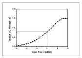
도 6은 본 발명에 따른 무선전력 송수신을 활용한 CCTV 시스템의 정류기를 통해 측정된 DC 전압의 출력을 나타낸 것이다.
도 7은 본 발명에 따른 무선전력 송수신을 활용한 CCTV 시스템의 정류기에서 입력전류별 변환 효율에 대한 측정 결과를 나타낸 것이다.FIG. 1 is a diagram illustrating a schematic configuration of a CCTV system using wireless power transmission / reception according to the present invention.
2 shows a circuit configuration of a rectifier of a CCTV system utilizing wireless power transmission / reception according to the present invention.
FIG. 3 is a graph illustrating a simulation result of energy conversion efficiency according to a width of a CMOS MOSPET constituting a DC voltage converter in a rectifier of a CCTV system utilizing wireless power transmission / reception according to the present invention.
FIG. 4 is a frequency spectrum of a rectifier of a CCTV system using wireless power transmission / reception according to the present invention, according to presence or absence of a low-pass filter.
FIG. 5 illustrates energy conversion efficiency according to a load resistance value in a rectifier of a CCTV system using wireless power transmission / reception according to the present invention.
FIG. 6 shows the output of a DC voltage measured through a rectifier of a CCTV system utilizing wireless power transmission / reception according to the present invention.
FIG. 7 is a graph illustrating a measurement result of conversion efficiency according to an input current in a rectifier of a CCTV system utilizing wireless power transmission / reception according to the present invention.
본 명세서 및 청구범위에 사용된 용어나 단어는 통상적이거나 사전적인 의미로 한정해서 해석되어서는 안되며, 발명자는 그 자신의 발명을 가장 최선의 방법으로 설명하기 위해 용어의 개념을 적절하게 정의할 수 있다는 원칙에 입각하여 본 발명의 기술적 사상에 부합하는 의미와 개념으로 해석되어야만 한다.The terms and words used in the present specification and claims should not be construed as limited to ordinary or dictionary meanings and the inventor can properly define the concept of the term to describe its invention in the best possible way And should be construed in accordance with the principles and meanings and concepts consistent with the technical idea of the present invention.
따라서 본 명세서에 기재된 실시 예와 도면에 도시된 구성은 본 발명의 가장 바람직한 실시 예에 불과할 뿐이고 본 발명의 기술적 사상을 모두 대변하는 것은 아니므로, 본 출원시점에 있어서 이들을 대체할 수 있는 다양한 균등물과 변형 예들이 있을 수 있음을 이해하여야 한다.Therefore, the embodiments described in the present specification and the configurations shown in the drawings are merely the most preferred embodiments of the present invention and are not intended to represent all of the technical ideas of the present invention. Therefore, various equivalents And variations are possible.
이하, 도면을 참조하여 설명하기에 앞서, 본 발명의 요지를 드러내기 위해서 필요하지 않은 사항 즉 통상의 지식을 가진 당업자가 자명하게 부가할 수 있는 공지 구성에 대해서는 도시하지 않거나, 구체적으로 기술하지 않았음을 밝혀둔다.Before describing the present invention with reference to the accompanying drawings, it should be noted that the present invention is not described or specifically described with respect to a known configuration that can be easily added by a person skilled in the art, Let the sound be revealed.
도 1은 본 발명에 따른 무선전력 송수신을 활용한 CCTV 시스템의 개략적인 구성을 나타낸 도면이다.FIG. 1 is a diagram illustrating a schematic configuration of a CCTV system using wireless power transmission / reception according to the present invention.
첨부된 도면의 도 1에 따른 CCTV장치(100)는 정류기(110), 촬영부(120), 태양전지패널(130), 배터리부(140), 제어부(150) 및 제1안테나(160)를 포함할 수 있고, 운용기기(200)는 제2안테나(210), 제어부(220) 및 모니터링 장치(230)를 포함할 수 있다.1 of the attached drawings, the
정류기(110)는 RF(주파수)신호를 DC(직류)전압으로 정류할 수 있는 것으로써, 더욱 구체적으로는 부궤환 회로를 통해 씨모스(CMOS) MOSFET에서 발생하는 문턱전압(Threshoid Voltage)에 의한 손실을 절감하여 정류의 효율을 증가시킬 수 있는 정류회로를 포함한다.The
여기에서 상기 정류기(110)에 관한 자세한 설명은 후술한다.Here, the
촬영부(120)는 피사체를 촬영할 수 있으며 태양전지패널(130) 또는 배터리부(140)의 전력을 통해 작동될 수 있다.The photographing
여기에서 상기 촬영부(120)는 바람직하게 IP카메라로 채택되어 후술될 운용장비(200)에서 촬영 영상을 실시간 모니터링 할 수 있도록 구성될 수 있으며, 360도 전 방향 촬영이 가능하도록 구성될 수도 있다.Here, the photographing
설계조건에 따라 상기 촬영부(120)는 PIR센서와 같은 움직임센서를 포함하여 인체의 움직임이 감지되면 피사체를 촬영하도록 구성될 수 있고 메모리모듈을 더 포함하여 상기 촬영부(120)에서 촬영된 영상을 저장하는 기능을 수행할 수도 있다.According to the design conditions, the photographing
또한, 상기 촬영부(120)에서 촬영되는 영상데이터 신호는 후술될 제1안테나(160)를 통해 무선 2.44GHZ 중심 주파수 대역을 이용하여 운용기기(200)에 송신될 수 있다.The image data signal photographed by the photographing
태양전지패널(130)은 태양광으로부터 에너지를 수집하여 전력을 생산하며, 다수의 태양전지셀이 직렬 또는 병렬로 연결되어 구성될 수 있다.The
또한, 상기 태양전지패널(130)은 제어부(150)를 통해 배터리부(140)를 충전시키는 기능을 수행할 수 있다.In addition, the
배터리부(140)는 상기 태양전지패널(130)로부터 충전되는 전력을 저장하여 사용될 수 있다.The
제어부(150)는 상기 정류기(110)로부터 출력된 전압을 통해 촬영부(120)가 구동되도록 제어할 수 있고, 태양전지패널(130)에서 생산되는 전류가 일정한 양으로 배터리부(140)에 충전되도록 제어할 수 있으며, 상기 배터리부(140)의 전력이 촬영부(120)에 전달되도록 제어할 수도 있다.The
또한, 상기 제어부(150)는 후술될 모니터링 장치(230)에서 제공한 제어신호에 따라 촬영부(120)를 제어할 수 있는데, 상기 제어의 예로는 카메라 회전, 영상 캡쳐 및 기기 재부팅 등을 들 수 있다.The
제1안테나(160)는 촬영부(120)로부터 제공받은 영상데이터 신호 및 정류회로(110)에서 제공받은 무선 전력을 제2안테나(210)에 송신할 수 있도록 구성되고, 제2안테나(210)로부터 제어신호를 수신하는 기능을 수행할 수 있다.The
제2안테나(210)는 모니터링 장치(230)에서 제공하는 제어신호를 상기 제1안테나(160)에 송신할 수 있도록 구성되고, 제1안테나(160)에서 송신한 영상데이터 신호 및 무선 전력을 수신하는 기능을 수행할 수 있다.The
여기에서 상기 제1안테나(160) 및 제2안테나(210)는 두 안테나 사이의 공진 주파수를 맞추어 공진 채널을 형성하고 이를 통하여 영상데이터 신호, 무선 전력 또는 제어신호를 송수신할 수 있다.The
제어부(220)는 상기 제1안테나(160)에서 수신받은 영상데이터 신호를 모니터링 장치(230)에 전달할 수 있다.The
또한, 상기 제어부(220)는 모니터링 장치(230)의 전력 또는 배터리가 방전되어 사용할 수 없을 경우 상기 제1안테나(160)에서 수신받은 무선 전력을 모니터링 장치(230)에 전달하는 기능을 수행할 수 있다.In addition, the
모니터링 장치(230)는 컴퓨터, 스마트 폰, 태블릿 PC 등과 같은 관리자의 디바이스에 상기 촬영부(120)에서 촬영되는 영상을 실시간으로 모니터링할 수 있도록 구성될 수 있다.The
상기 모니터링 장치(230)는 관리자의 제어에 따라 상기 촬영부(120)에 제어신호를 송신하여 촬영부(120)를 제어할 수도 있는데 상기 제어의 예로는 카메라 회전, 영상 캡쳐 및 기기 재부팅 등을 들 수 있다.The
이하에서는, 본 발명에 따른 RF(주파수) 신호를 DC(직류)전압으로 정류할 수 있는 정류기에 대한 설명과 더욱 구체적으로는 부궤환 회로를 통해 씨모스(CMOS) MOSFET에서 발생하는 문턱전압(Threshoid Voltage)에 의한 손실을 절감하여 정류의 효율을 증가시킬 수 있는 정류회로를 첨부된 도면의 도 2 내지 도 7을 첨부하여 설명한다.Hereinafter, a rectifier capable of rectifying an RF (frequency) signal according to the present invention to a DC (direct current) voltage, and more specifically, a rectifier capable of rectifying a RF 2 to 7 of the accompanying drawings will be described with reference to the accompanying drawings.
본 발명에 따른 정류기(110)는 동부 하이텍 RF CMOS 0.11㎛ 공정을 이용하여 설계된 것으로, 2.44GHz의 동작 RF신호를 갖고, 0dBm(decibles above 1 milliwatt)의 입력전력에서 30%의 변환 효율을 갖으며, 출력 전압은 0.7V가 되도록 설계된다.The
또한 본 발명은 칩으로 구성되되 그 크기가 780 x 640㎛2으로 구성될 수 있다. 이러한 정류기(110)의 회로를 설계하는데 이용된 시뮬레이션 및 레이아웃 프로그램은 Cadence사의 Spectre 및 Virtuoso 프로그램을 이용하였다.In addition, the present invention may be configured as a chip, and its size may be 780 x 640 탆2 . The simulation and layout program used to design the circuit of this
설명에 앞서, 상술된 정류회로는 CMOS(Complementary Metal-Oxide Semiconductor, 씨모스) 공정으로 설계될 수 있는데, 이는 p채널의 MOS 트랜지스터와 n채널의 MOS 트랜지스터가 서로 절연하여 동일한 칩에서 상보적으로 동작하도록 하는 것으로, 소비전력은 ㎼ 정도이고, 동작은 고속이 가능하며, 잡음 배제성이 좋은 것으로 알려져있다.Prior to the description, the above-described rectifying circuit can be designed in a CMOS (Complementary Metal-Oxide Semiconductor) process, in which a p-channel MOS transistor and an n-channel MOS transistor are insulated from each other and operate complementarily It is known that the power consumption is about ㎼, the operation speed is high, and the noise rejection is good.
또한, 일반적인 RF신호 정류 회로에서는 문턱전압이 낮은 쇼트키 다이오드를 적용하고 있지만, 상술된 씨모스 공정을 이용하는 정류 회로에서는 제조 단가 및 공정 기술의 문제로 쇼트키 다이오드의 사용이 제한된다.Although a Schottky diode having a low threshold voltage is applied in a general RF signal rectification circuit, the use of the Schottky diode is limited in the rectifier circuit using the above-described CMOS process because of manufacturing cost and process technology.
따라서, 쇼트키 다이오드를 사용하지 않으면서 문턱전압에 의한 손실을 절감할 수 있도록 해야 하는데, 본 발명에서는 RF신호로부터 변환된 직류 전압을 부궤환하여 MOSFET 바디에 인가하는 바디 바이어스 부궤환 회로 기법을 적용하여 바디 바이어스를 통해 문턱전압에 의한 손실을 절감하고자 한다.Therefore, it is necessary to reduce the loss due to the threshold voltage without using the Schottky diode. In the present invention, the body bias feedback circuit technique of applying the DC voltage converted from the RF signal to the MOSFET body by negative feedback is applied Thereby reducing the loss due to the threshold voltage through the body bias.
먼저, 아래 [수학식 1]은 통상의 CMOS 공정에서 바디 효과에 따른 MOSFET 문턱전압을 표현하기 위한 수식이다.First, Equation (1) below is a formula for expressing a MOSFET threshold voltage according to a body effect in a normal CMOS process.
여기서, 바디 효과는 본 명세서에서 바디 바이어스라고도 지칭될 수 있으며, 이는 MOSFET 바디(M1, M2)의 최적화된 너비에 따라 문턱전압이 절감되는 효과를 의미한다.Here, the body effect can also be referred to herein as body bias, which means that the threshold voltage is reduced according to the optimized width of the MOSFET body M1, M2.

위 [수학식 1]에서 VTH0, r, ΦF, VSB는 각각 전위차가 0V일 때의 초기문턱전압, 바디효과계수, 실리콘 기판 표면의 전위, MOSFET의 소스와 바디의 전위차를 나타낸다.In Equation (1), VTH0 , r, ΦF , and VSB represent the initial threshold voltage, the body effect coefficient, the potential of the surface of the silicon substrate, and the potential difference between the source and the body of the MOSFET when the potential difference is 0V, respectively.
이때 VTH0, r, ΦF는 제조 공정상에서 전해지는 값으로서, 실리콘 기판의 도핑 농도 및 공핍 영역의 전하량, 실리콘 기판의 일함수 등에 의해 결정되는 값이기 때문에 임의로 변경될 수 없다.At this time, VTH0 , r, and?F are values that are transferred in the manufacturing process and can not be arbitrarily changed because they are determined by the doping concentration of the silicon substrate, the charge amount of the depletion region, and work function of the silicon substrate.
다만, 소스와 바디의 전위차인 VSB를 통해서 회로 설계시 모스펫의 문턱전압을 임의로 조절할 수 있다.However, the threshold voltage of the MOSFET can be arbitrarily adjusted during circuit design through VSB , which is the potential difference between the source and the body.
이에 앞서, 고정값인 ΦF와 임의로 조정 가능한 VSB의 문턱전압의 표현식을 살펴보면 아래 [수학식 2]와 같다.Prior to this, the expression of the threshold voltage of the fixed value?F and the arbitrary adjustable threshold voltage VSB is as follows.


위의 [수학식 2]를 참조하면, VSB가 -2ΦF≤ VSB < 0 인 범주 내에 있을 때 문턱전압 VTH는 일반적인 모스펫의 문턱전압 VTH0 보다 작은 값을 갖음을 알 수 있었고, 특히 아래 [수학식 3]과 같이 VSB가 -2ΦF 일 때 최소 값을 갖는 것을 알 수 있었다.Referring to the above equation (2), when VSB is -2ΦF It can be seen that the threshold voltage VTH is smaller than the threshold voltage VTH0 of a general MOSFET when the voltage VSB is within the range of VSB <0. In particular, when VSB is -2ΦF , Value. ≪ / RTI >

상술된 수학식을 통해 문턱전압을 절감함으로써, 전압의 변환 효율을 증진시킬 수 있는 본 발명에 따른 정류기(110)는, 수신부(111), DC전압변환부(112), 부궤환부(113), 저역통과여파부(114), 부하저항부(115) 및 전압출력부(116)를 포함하여 구성될 수 있는데, 바람직하게는 첨부된 도면의 도 2와 같이 Villard 배전압 구조의 회로로 구현될 수 있다.The
도 2는 본 발명에 따른 무선전력 송수신을 활용한 CCTV 시스템의 정류기의 회로구성을 나타낸 것이다.2 shows a circuit configuration of a rectifier of a CCTV system utilizing wireless power transmission / reception according to the present invention.
수신부(111)는 회로의 일단에서 2.44GHz 영역의 RF신호를 수신할 수 있다. 이러한 수신부(111)는 전송선로 및 높은 Q-지수를 갖는 칩(chip) 커패시터를 이용하여 구성될 수 있으며, 2.44GHz의 RF신호에서 높은 반사 특성을 갖도록 한다.The receiving
DC전압변환부(112)는 수신부(111)의 다음 단에 위치하는 MOSFET 소자의 형태로 구성될 수 있다.The DC
이때 MOSFET이란, 금속 산화막 반도체 전계효과 트랜지스터(MOS, field-effect transistor)의 준말로서, DC전압변환부(112)의 교차동작에 의해 수신된 RF신호가 DC전압으로 변환되도록 한다.At this time, the MOSFET is a generic term of a metal oxide semiconductor field effect transistor (MOS), and allows the RF signal received by the crossing operation of the DC
그리고 DC전압변환부(112)는 도 2와 같이 M1 바디 및 M2 바디로 구성할 수 있는데, 이때 변환된 DC전압은 후술될 부궤환부(113)를 통해 M1 바디 및 M2 바디로 분류되어 인가된다.As shown in FIG. 2, the DC
여기서 M1 바디 및 M2 바디로 인가된 DC전압은 전위차가 발생되는데, 상기 [수학식 2]에 따라 선택된 0dBm의 입력전력에서 문턱전압을 낮춤으로 손실을 최소화하여 변환 효율을 높일 수 있도록 한다.Here, a potential difference is generated in the DC voltage applied to the M1 body and the M2 body. By reducing the threshold voltage at the input power of 0dBm selected according to Equation (2), loss can be minimized and conversion efficiency can be increased.
이때 DC전압변환부(112)는 입력전력이 0dBm보다 너무 낮거나 높아지지 않도록 각각의 M1 바디 및 M2 바디의 너비(width)가 최적화될 필요가 있는데, 본 발명에서는 M1 바디의 너비를 50㎛로 하고, M2 바디의 너비를 30㎛로 한다.At this time, the
이에 대한 근거로서, 첨부된 도면의 도 3을 참조할 수 있는데, 도 3은 본 발명에 따른 무선전력 송수신을 활용한 CCTV 시스템의 정류기에서 DC전압변환부의 너비에 따른 에너지 변환 효율에 대한 시뮬레이션 결과를 나타낸 것이다.FIG. 3 is a graph illustrating a simulation result of energy conversion efficiency according to a width of a DC voltage converter in a rectifier of a CCTV system using wireless power transmission / reception according to the present invention. .
도 3을 참조하면, M1 바디의 너비가 50㎛이고, M2 바디의 너비가 30㎛인 경우가 0dBm의 입력전력에서 40%을 초과하는 변환 효율을 보임으로써 다른 경우보다 높은 효율을 보이고 있다.Referring to FIG. 3, when the width of the M1 body is 50 탆 and the width of the M2 body is 30 탆, the conversion efficiency exceeds 40% at an input power of 0 dBm.
부궤환부(113)는 DC전압변환부(112)를 통해 변환되어 출력되는 DC전압(출력전압)을 부궤환하여 다시 M1 바디 및 M2 바디를 포함하는 DC전압변환부(112)로 DC전압을 인가하도록 하는 것으로, 도 2에서는 Rf 및 Cf로 도시되어 있다.The
여기서, Rf는 M1 바디로부터 출력된 DC전압을 M1 바디로 재인가하는 기능을 수행하는 수단이며, Cf는 M2 바디로부터 출력된 DC전압을 M2 바디로 재인가하는 기능을 수행하는 수단이다.Here, Rf is a means for re-applying the DC voltage output from the M1 body to the M1 body, and Cf is a means for re-applying the DC voltage output from the M2 body to the M2 body.
이때 M1 바디 및 M2 바디에 인가된 DC전압 간의 전위차가 발생될 수 있는데, 위와 같이 M1 바디 및 M2 바디의 너비를 각각 50㎛ 및 30㎛로 결정함에 따라 상술된 수학식에 근거하여 결정된 0dBm의 입력전력에서는 문턱전력이 절감되어 손실이 최소화될 수 있도록 한다.At this time, a potential difference may be generated between the M1 body and the M2 voltage applied to the M2 body. When the widths of the M1 body and the M2 body are determined to be 50 mu m and 30 mu m, respectively, the input of 0dBm determined based on the above- In power, the threshold power is reduced so that the losses can be minimized.
저역통과여파부(114)는 부궤환되어 다시 출력된 직류 전압과 DC전압변환부(112)에서 발생되는 고조파 성분들을 차단하는 기능을 수행할 수 있다.The low-
이러한 저역통과여파부(114)는 부궤환되어 M1 바디로부터 출력된 DC전압과 M1 바디에서 발생되는 고조파 성분을 차단하는 수단(Llpf) 및 부궤환되어 M2 바디로부터 출력된 DC전압과 M2 바디에서 발생되는 고조파 성분을 차단하는 수단(Clpf)으로 구성될 수 있다.The low-
이와 같은 저역통과여파부(114)는 첨부된 도면의 도 4에서 볼 수 있듯이, M1 바디 및 M2 바디로부터 부궤환되어 다시 출력된 DC전압이 평탄화되어, 저역통과여파부(114)가 구비되지 않았을 때보다 상대적으로 선형에 가까운 스펙트럼을 보이고 있다.As shown in FIG. 4 of the accompanying drawings, the low-
도 4는 본 발명에 따른 무선전력 송수신을 활용한 CCTV 시스템의 정류기에서 저역통과여파부의 유무에 따라 나타나는 주파수 스펙트럼을 나타낸 것이다.FIG. 4 is a frequency spectrum of a rectifier of a CCTV system using wireless power transmission / reception according to the present invention, according to presence or absence of a low-pass filter.
한편, 상기와 같이 씨모스 공정을 이용하는 정류기를 구현하는데 있어서, 전력의 변환 효율은 DC전압변환부(112)를 구성하는 MOSFET M1과 M2의 너비 비율 또는 부하 저항의 값이 큰 영향을 미친다.On the other hand, in the implementation of the rectifier using the CMOS process as described above, the power conversion efficiency has a large influence on the width ratio of the MOSFETs M1 and M2 or the value of the load resistance constituting the DC
그러나 앞에서 언급한 바와 같이 DC전압변환부(112)를 구성하는 MOSFET의 M1과 M2의 너비는 본 발명에서 설정한 0dBm의 입력전력에 대해 상술된 수학식을 기반으로 최적화되었으므로, 부하 저항 값이 최적화될 수 있어야 한다.However, since the widths M1 and M2 of the MOSFETs constituting the
이를 위해 저역통과여파부(114)의 다음 단에 부하저항부(115)를 구성하는데, 이때 부하저항부(115)에 걸리는 부하 저항값을 설정하기 위해 첨부된 도면의 도 5를 첨부한다.To this end, a
도 5는 본 발명에 따른 무선전력 송수신을 활용한 CCTV 시스템의 정류기에서 부하 저항값에 따른 에너지 변환 효율을 나타낸 것이다.FIG. 5 illustrates energy conversion efficiency according to a load resistance value in a rectifier of a CCTV system using wireless power transmission / reception according to the present invention.
첨부된 도면의 도 5에 따르면, 부하 저항값이 클수록 작은 입력전력에서 에너지 변환효율이 높은 것으로 나타나는데, 이러한 효율은 입력전력이 높아질수록 점점 감소하는 것으로 나타났다.According to FIG. 5 of the accompanying drawings, the larger the load resistance value, the higher the energy conversion efficiency at a small input power. This efficiency decreases gradually as the input power increases.
그리고 본 발명에서 목표전력으로 하는 0dBm의 입력전력에서는 4㏀ 또는 8㏀이 35% 이상의 변환효율을 나타내어 부하저항부(115)의 부하 저항값으로 적당함을 나타냈다.In the present invention, 4 k [Omega] or 8 k [Omega] exhibits a conversion efficiency of 35% or more at an input power of 0 dBm as a target power, which is appropriate as the load resistance value of the
전압출력부(116)는 변환된 DC전압을 출력하는 기능을 수행하는 것으로, 목표 입력전력인 0dBm에서 0.7V의 DC전압을 출력할 수 있다.The
이는 첨부된 도면의 도 6을 참조할 수 있는데, 도 6은 본 발명에 따른 무선전력 송수신을 활용한 CCTV 시스템의 정류기를 통해 측정된 DC 전압의 출력을 나타낸 것이다.6, which illustrates the output of a DC voltage measured through a rectifier of a CCTV system utilizing wireless power transmission / reception according to the present invention.
이상과 같이 구성되는 본 발명에서 입력전력을 0dBm으로 설정한 것에 대한 근거를 살펴보기 위해 첨부된 도면의 도 7을 참조한다.In order to understand the reason why the input power is set to 0 dBm in the present invention configured as above, refer to FIG. 7 of the accompanying drawings.
도 7은 본 발명에 따른 무선전력 송수신을 활용한 CCTV 시스템의 정류기에서 입력전류별 변환 효율에 대한 측정 결과를 나타낸 것이다.FIG. 7 is a graph illustrating a measurement result of conversion efficiency according to an input current in a rectifier of a CCTV system utilizing wireless power transmission / reception according to the present invention.
첨부된 도면의 도 7은 설계된 회로(도 2 참조)의 레이아웃에 대해 DC전압변환부의 이동도 변화 결과를 예측할 수 있는 시뮬레이션을 나타내고 있는데, 이에 따르면 -4 내지 5dBM의 입력전력에 대해 30% 이상의 변환효율을 갖으며, 이 범주 내의 입력전력에서는 DC전압변환부의 이동도가 주어진 대표 값(Typical)보다 빠른(Fast) 형상을 보이고 있다.FIG. 7 of the accompanying drawings shows a simulation capable of predicting the result of mobility change of the DC voltage conversion portion with respect to the layout of the designed circuit (see FIG. 2), whereby according to the input power of -4 to 5 dBm, And the mobility of the DC voltage converter is faster than the given typical value at the input power in this category.
그리고 이 중에서 0dBm의 입력전력 근처에서 변환효율이 가장 높은 것으로 나타나고 있으며, 이보다 너무 작은 입력전력에서는 변환효율이 감소하고 있으며, 큰 입력전력에서는 대표 값을 초과하고 있다.Among them, the conversion efficiency is the highest near 0dBm input power, and the conversion efficiency is decreased at the input power which is much smaller than this, and exceeds the representative value at the large input power.
한편, 상기에서 도 1 내지 도 7을 이용하여 서술한 것은, 본 발명의 주요 사항만을 서술한 것으로, 그 기술적 범위 내에서 다양한 설계가 가능한 만큼, 본 발명이 도 1 내지 도 7의 구성에 한정되는 것이 아님은 자명하다.1 to 7 have described only the main points of the present invention. As various designs can be made within the technical scope of the present invention, the present invention is limited to the configurations of Figs. 1 to 7 It is self-evident.
100 : CCTV장치 110 : 정류기
111 : 수신부 112 : 전압변환부
113 : 부궤환부 114 : 저역통과여파부
115 :부하저항부 116 : 전압출력부
120 : 촬영부 130 : 태양전지패널
140 : 배터리부 150 : 제어부
160 : 제1안테나 200 : 운용장치
210 : 제2안테나 220 : 제어부
230 : 모니터링 장치100: CCTV device 110: rectifier
111: Receiver 112: Voltage converter
113: negative feedback section 114: low-pass filter section
115: load resistor section 116: voltage output section
120: photographing part 130: solar cell panel
140: battery unit 150:
160: First antenna 200: Operation device
210: second antenna 220:
230: Monitoring device
Claims (8)
Translated fromKorean상기 CCTV 시스템은, CCTV장치(100) 및 운용기기(200)로 구성되며,
상기 CCTV장치(100)는,
RF 신호를 DC전압으로 정류하는 정류회로를 포함하고, 출력 전압 효율을 증가시킬 수 있는 정류기(110);
영상을 촬영할 수 있는 촬영부(120);
상기 정류기(110)로부터 출력된 전압을 통해 촬영부(120)가 구동되도록 제어할 수 있는 제어부(150); 및
상기 운용기기(200)에 영상데이터 신호 및 무선 전력을 제공할 수 있는 제1안테나(160)를 포함하고,
상기 운용기기(200)는,
상기 CCTV장치(100)에 제어신호를 제공할 수 있는 제2안테나(210);
상기 CCTV장치(100)에서 수신받은 영상데이터 신호를 모니터링 장치(230)에 전달하고, 모니터링 장치(230)의 전력 또는 배터리가 방전되어 사용할 수 없는 경우 상기 CCTV장치(100)에서 수신받은 무선 전력을 모니터링 장치(230)에 전달할 수 있도록 하는 제어부(220); 및
촬영부(120)에서 촬영되는 영상을 실시간으로 모니터링할 수 있고, 촬영부(120)의 기기를 제어할 수 있도록 제어신호를 제공하는 모니터링 장치(230);를 포함하되,
상기 정류기(110)는,
RF신호를 수신하는 수신부(111);
상기 수신부(111)의 다음 단에 복수 개의 소자의 교차 동작에 의해 수신된 RF신호를 DC전압으로 변환하는 DC전압변환부(112);
상기 DC전압변환부(112)에서 변환된 DC전압을 부궤환시키는 부궤환부(113);
상기 부궤환부(113)을 통해 부궤환된 DC전압과 상기 DC전압변환부(112)에서 발생되는 고조파 성분을 차단하는 저역통과여파부(114);
상기 저역통과여파부(114)의 다음 단에 위치되어 기설정된 부하 저항값을 갖는 부하저항부(115); 및
상기 부하저항부(115)의 다음 단에 위치되어 상기 저역통과여파부(114)를 통과한 DC전압을 출력하는 전압출력부(116);를 포함하고,
상기 DC전압변환부(112)는,
MOSFET으로 구성되는 M1 바디 및 M2 바디로 구성되며,
상기 M1과 M2의 너비는 목표 입력전력에서 최대 출력 DC전압을 획득하도록 최적화되어 있으며,
상기 부궤환부(113)는,
DC전압변환부(112)를 구성하는 MOSFET M1 바디에서 출력된 DC전압을 기반으로 0dBm의 입력전력을 상기 M1 바디에 재인가하여 부궤환시킬 수 있는 수단; 및
M2 바디에서 출력된 DC전압을 기반으로 0dBm의 입력전력을 상기 M2 바디에 재인가하여 부궤환시킬 수 있는 수단;을 포함하고,
상기 저역통과여파부(114)는,
부궤환되어 M1 바디를 통해 출력된 DC전압과 M1 바디에서 발생되는 고조파 성분을 차단할 수 있는 수단; 및
부궤환되어 M2 바디를 통해 출력된 DC전압과 M2 바디에서 발생되는 고조파 성분을 차단할 수 있는 수단;을 포함하여 구성되는 것을 특징으로 하는, 무선전력 송수신을 활용한 CCTV 시스템.
In a CCTV system utilizing wireless power transmission / reception,
The CCTV system includes a CCTV apparatus 100 and a working device 200,
The CCTV apparatus (100)
A rectifier (110) including a rectifier circuit for rectifying the RF signal to a DC voltage and capable of increasing the output voltage efficiency;
A photographing unit 120 capable of photographing an image;
A controller 150 for controlling the photographing unit 120 to be driven through a voltage output from the rectifier 110; And
And a first antenna (160) capable of providing a video data signal and a wireless power to the operating device (200)
The operating device (200)
A second antenna 210 capable of providing a control signal to the CCTV device 100;
The video data signal received from the CCTV apparatus 100 is transmitted to the monitoring apparatus 230 and the wireless power received from the CCTV apparatus 100 when the power of the monitoring apparatus 230 or the battery is discharged and can not be used, A control unit (220) for allowing the monitoring device (230) to communicate with the monitoring device (230); And
And a monitoring device 230 for monitoring the image photographed by the photographing part 120 in real time and providing a control signal for controlling the device of the photographing part 120,
The rectifier (110)
A receiving unit 111 for receiving an RF signal;
A DC voltage conversion unit 112 for converting an RF signal received by the crossing operation of a plurality of elements to a DC voltage at the next stage of the receiving unit 111;
A negative feedback unit (113) for negative feedback of the DC voltage converted by the DC voltage conversion unit (112);
A low pass filter 114 for blocking a DC voltage negatively fed through the negative feedback unit 113 and a harmonic component generated in the DC voltage conversion unit 112;
A load resistance section 115 positioned at the next stage of the low-pass filter section 114 and having a predetermined load resistance value; And
And a voltage output unit (116) located at the next stage of the load resistance unit (115) and outputting a DC voltage having passed through the low-pass filter unit (114)
The DC voltage converter 112 converts the DC voltage
It consists of an M1 body and an M2 body,
The widths of M1 and M2 are optimized to obtain the maximum output DC voltage at the target input power,
The sub-feedback section (113)
Means for re-applying 0 dBm of input power to the M1 body based on the DC voltage output from the MOSFET M1 body constituting the DC voltage conversion unit 112 so as to perform negative feedback; And
Means for re-applying 0dBm of input power to the M2 body based on the DC voltage output from the M2 body for negative feedback,
The low-pass filter 114,
Means for blocking the DC voltage output through the M1 body and the harmonic components generated in the M1 body by negative feedback; And
And a means for blocking the DC voltage output through the M2 body and the harmonic components generated in the M2 body by negative feedback.
상기 부하저항부(115)가 갖는 기설정된 부하 저항값은,
전압출력부(116)에서 획득되는 전력이 최적화되도록 하는 것을 갖는 것을 특징으로 하는, 무선전력 송수신을 활용한 CCTV 시스템.
The method according to claim 1,
The predetermined load resistance value of the load resistance section 115 is,
So that the power obtained at the voltage output (116) is optimized.
문턱전압을 표현하는 아래 수식에 대해,
VSB가 -2ΦF일 때 가장 작은 문턱전압을 갖는 것을 특징으로 하는, 무선전력 송수신을 활용한 CCTV 시스템.

(단, VTH0 = 초기문턱전압, r = 바디효과계수, ΦF = 실리콘 기판 표면의 전위, VSB = 모스펫의 소스와 바디의 전위차를 나타냄.)
The method according to claim 1,
For the expression below representing the threshold voltage,
And has the smallest threshold voltage when VSB is -2?F.
(Where VTH0 = initial threshold voltage, r = body effect coefficient, ΦF = potential of silicon substrate surface, and VSB = potential difference between source and body of MOSFET).
상기 CCTV장치(100)는,
태양광을 기반하여 전력을 제공할 수 있는 태양전지패널(130); 및
상기 태양전지패널(130)에서 제공한 전력을 저장하여 사용될 수 있는 배터리부(140);를 더 포함하되,
상기 제어부(150)는,
상기 태양전지패널(130)에서 제공한 전력이 배터리부(140)에 저장될 수 있도록 하고, 상기 배터리부(140)에 저장된 전력을 통해 촬영부(120)가 구동되도록 제어하는 것을 특징으로 하는 무선전력 송수신을 활용한 CCTV 시스템.The method according to claim 1,
The CCTV apparatus (100)
A solar panel (130) capable of providing power based on sunlight; And
And a battery unit 140 that can be used to store the power provided by the solar cell panel 130,
The control unit 150,
The power supplied from the solar cell panel 130 may be stored in the battery unit 140 and the camera unit 120 may be driven through the power stored in the battery unit 140. [ CCTV system using power transmission and reception.
Priority Applications (1)
| Application Number | Priority Date | Filing Date | Title |
|---|---|---|---|
| KR1020150166217AKR101683248B1 (en) | 2015-11-26 | 2015-11-26 | Cctv system to using wireless power transmission and reception |
Applications Claiming Priority (1)
| Application Number | Priority Date | Filing Date | Title |
|---|---|---|---|
| KR1020150166217AKR101683248B1 (en) | 2015-11-26 | 2015-11-26 | Cctv system to using wireless power transmission and reception |
Publications (1)
| Publication Number | Publication Date |
|---|---|
| KR101683248B1true KR101683248B1 (en) | 2016-12-06 |
Family
ID=57576489
Family Applications (1)
| Application Number | Title | Priority Date | Filing Date |
|---|---|---|---|
| KR1020150166217AActiveKR101683248B1 (en) | 2015-11-26 | 2015-11-26 | Cctv system to using wireless power transmission and reception |
Country Status (1)
| Country | Link |
|---|---|
| KR (1) | KR101683248B1 (en) |
Cited By (2)
| Publication number | Priority date | Publication date | Assignee | Title |
|---|---|---|---|---|
| KR20180066341A (en)* | 2016-12-08 | 2018-06-19 | 조선대학교산학협력단 | Wireless CCTV system using multi-band antenna |
| CN108513076A (en)* | 2017-10-02 | 2018-09-07 | 洪瑛翎 | Portable wireless charging safety device, system and application method thereof |
Citations (4)
| Publication number | Priority date | Publication date | Assignee | Title |
|---|---|---|---|---|
| KR20120086963A (en)* | 2011-01-27 | 2012-08-06 | 조동혁 | The remote control security camera system which movable in transparent window pipe |
| KR20130089808A (en)* | 2012-01-03 | 2013-08-13 | 주식회사 오엠플렛폼 | Wireless portable communication system |
| KR20140070965A (en)* | 2012-12-03 | 2014-06-11 | 엘에스전선 주식회사 | Wireless Power Transmission System, Wireless Power Receiving Apparatus and Wireless Power Receiving Method |
| KR20140101215A (en)* | 2013-02-08 | 2014-08-19 | 삼성전자주식회사 | Iip2 calibration method of a mixer in a wierless communication system and the mixer using the same |
- 2015
- 2015-11-26KRKR1020150166217Apatent/KR101683248B1/enactiveActive
Patent Citations (5)
| Publication number | Priority date | Publication date | Assignee | Title |
|---|---|---|---|---|
| KR20120086963A (en)* | 2011-01-27 | 2012-08-06 | 조동혁 | The remote control security camera system which movable in transparent window pipe |
| KR20130089808A (en)* | 2012-01-03 | 2013-08-13 | 주식회사 오엠플렛폼 | Wireless portable communication system |
| KR101383018B1 (en) | 2012-01-03 | 2014-04-22 | 주식회사 오엠플렛폼 | Wireless portable communication system |
| KR20140070965A (en)* | 2012-12-03 | 2014-06-11 | 엘에스전선 주식회사 | Wireless Power Transmission System, Wireless Power Receiving Apparatus and Wireless Power Receiving Method |
| KR20140101215A (en)* | 2013-02-08 | 2014-08-19 | 삼성전자주식회사 | Iip2 calibration method of a mixer in a wierless communication system and the mixer using the same |
Cited By (2)
| Publication number | Priority date | Publication date | Assignee | Title |
|---|---|---|---|---|
| KR20180066341A (en)* | 2016-12-08 | 2018-06-19 | 조선대학교산학협력단 | Wireless CCTV system using multi-band antenna |
| CN108513076A (en)* | 2017-10-02 | 2018-09-07 | 洪瑛翎 | Portable wireless charging safety device, system and application method thereof |
Similar Documents
| Publication | Publication Date | Title |
|---|---|---|
| Talla et al. | Powering the next billion devices with Wi-Fi | |
| US20210184503A1 (en) | Wireless power receiver with a transistor rectifier | |
| Talla et al. | Battery-free cellphone | |
| KR102148638B1 (en) | Apparatus for fever detection according to the change of external environment | |
| US10158401B2 (en) | Intelligent network sensor system | |
| CN211209701U (en) | Wireless charging device and terminal | |
| Gudan et al. | A 2.4 GHz ambient RF energy harvesting system with− 20dBm minimum input power and NiMH battery storage | |
| EP2381328A3 (en) | Robot cleaner and remote monitoring system using the same | |
| US8390720B2 (en) | Advanced magnification device and method for low-power sensor systems | |
| US20200119585A1 (en) | An energy harvester to convert incident radio frequency energy to direct current as well as a corresponding method and sensor comprising the energy harvester | |
| KR101683248B1 (en) | Cctv system to using wireless power transmission and reception | |
| EP4175311A1 (en) | Photon counting image sensor, image acquisition apparatus and electronic apparatus including the image acquisition apparatus | |
| CN106033973A (en) | Wearable device | |
| CN211720339U (en) | Wireless charging device and terminal | |
| Jha et al. | War field spying robot with night vision camera | |
| CN105580356A (en) | Information processing device and information processing method | |
| Sampe et al. | Ultra-low power RF energy harvesting of 1.9 GHz & 2.45 GHz narrow-band rectenna for battery-less remote control | |
| US20140111149A1 (en) | Battery and charging system using the same | |
| US20200275063A1 (en) | Method and Apparatus for Wildlife Monitoring | |
| CN114189576A (en) | Electronic device | |
| US20210194291A1 (en) | Electronic device for receiving power wirelessly and method for operating same | |
| KR102282472B1 (en) | Surveillance system and operation method thereof | |
| Thierry et al. | RF energy harvesting and remote powering at 900MHz and 2.4 GHz | |
| Diagarajan et al. | Advanced radio frequency energy harvesting with power management from multiple sources for low power sensors and mobile charging applications | |
| US11770798B2 (en) | Surveillance method and apparatus |
Legal Events
| Date | Code | Title | Description |
|---|---|---|---|
| PA0109 | Patent application | Patent event code:PA01091R01D Comment text:Patent Application Patent event date:20151126 | |
| PA0201 | Request for examination | ||
| PA0302 | Request for accelerated examination | Patent event date:20160526 Patent event code:PA03022R01D Comment text:Request for Accelerated Examination Patent event date:20151126 Patent event code:PA03021R01I Comment text:Patent Application | |
| PE0902 | Notice of grounds for rejection | Comment text:Notification of reason for refusal Patent event date:20160602 Patent event code:PE09021S01D | |
| E701 | Decision to grant or registration of patent right | ||
| PE0701 | Decision of registration | Patent event code:PE07011S01D Comment text:Decision to Grant Registration Patent event date:20161018 | |
| GRNT | Written decision to grant | ||
| PR0701 | Registration of establishment | Comment text:Registration of Establishment Patent event date:20161130 Patent event code:PR07011E01D | |
| PR1002 | Payment of registration fee | Payment date:20161130 End annual number:3 Start annual number:1 | |
| PG1601 | Publication of registration | ||
| FPAY | Annual fee payment | Payment date:20191120 Year of fee payment:4 | |
| PR1001 | Payment of annual fee | Payment date:20191120 Start annual number:4 End annual number:4 | |
| PR1001 | Payment of annual fee | Payment date:20221128 Start annual number:7 End annual number:7 | |
| PR1001 | Payment of annual fee | Payment date:20231127 Start annual number:8 End annual number:8 |