KR101682574B1 - Engaging apparatus of unmanned aerial vehicle and unmanned aerial vehicle - Google Patents
Engaging apparatus of unmanned aerial vehicle and unmanned aerial vehicleDownload PDFInfo
- Publication number
- KR101682574B1 KR101682574B1KR1020150181495AKR20150181495AKR101682574B1KR 101682574 B1KR101682574 B1KR 101682574B1KR 1020150181495 AKR1020150181495 AKR 1020150181495AKR 20150181495 AKR20150181495 AKR 20150181495AKR 101682574 B1KR101682574 B1KR 101682574B1
- Authority
- KR
- South Korea
- Prior art keywords
- cargo
- contacting portion
- supporting
- cargo contacting
- adjusting
- Prior art date
- Legal status (The legal status is an assumption and is not a legal conclusion. Google has not performed a legal analysis and makes no representation as to the accuracy of the status listed.)
- Expired - Fee Related
Links
Images


Classifications
- B—PERFORMING OPERATIONS; TRANSPORTING
- B64—AIRCRAFT; AVIATION; COSMONAUTICS
- B64D—EQUIPMENT FOR FITTING IN OR TO AIRCRAFT; FLIGHT SUITS; PARACHUTES; ARRANGEMENT OR MOUNTING OF POWER PLANTS OR PROPULSION TRANSMISSIONS IN AIRCRAFT
- B64D1/00—Dropping, ejecting, releasing or receiving articles, liquids, or the like, in flight
- B—PERFORMING OPERATIONS; TRANSPORTING
- B64—AIRCRAFT; AVIATION; COSMONAUTICS
- B64C—AEROPLANES; HELICOPTERS
- B64C27/00—Rotorcraft; Rotors peculiar thereto
- B64C27/04—Helicopters
- B64C27/08—Helicopters with two or more rotors
- B—PERFORMING OPERATIONS; TRANSPORTING
- B64—AIRCRAFT; AVIATION; COSMONAUTICS
- B64C—AEROPLANES; HELICOPTERS
- B64C39/00—Aircraft not otherwise provided for
- B64C39/02—Aircraft not otherwise provided for characterised by special use
- B64C39/024—Aircraft not otherwise provided for characterised by special use of the remote controlled vehicle type, i.e. RPV
- B—PERFORMING OPERATIONS; TRANSPORTING
- B64—AIRCRAFT; AVIATION; COSMONAUTICS
- B64D—EQUIPMENT FOR FITTING IN OR TO AIRCRAFT; FLIGHT SUITS; PARACHUTES; ARRANGEMENT OR MOUNTING OF POWER PLANTS OR PROPULSION TRANSMISSIONS IN AIRCRAFT
- B64D1/00—Dropping, ejecting, releasing or receiving articles, liquids, or the like, in flight
- B64D1/22—Taking-up articles from earth's surface
- B—PERFORMING OPERATIONS; TRANSPORTING
- B64—AIRCRAFT; AVIATION; COSMONAUTICS
- B64D—EQUIPMENT FOR FITTING IN OR TO AIRCRAFT; FLIGHT SUITS; PARACHUTES; ARRANGEMENT OR MOUNTING OF POWER PLANTS OR PROPULSION TRANSMISSIONS IN AIRCRAFT
- B64D47/00—Equipment not otherwise provided for
- B64C2201/128—
Landscapes
- Engineering & Computer Science (AREA)
- Aviation & Aerospace Engineering (AREA)
- Mechanical Engineering (AREA)
- Forklifts And Lifting Vehicles (AREA)
Abstract
Description
Translated fromKorean본 발명은 무인 항공기용 화물 고정 장치 및 무인 항공기에 관한 것으로, 더욱 구체적으로는 무인 항공기에 의해서 배송될 박스 형상의 화물의 크기에 대한 제한을 최소화하는 무인 항공기용 화물 고정 장치 및 무인 항공기에 관한 것이다.The present invention relates to a cargo holding device for a UAV and an unmanned airplane, and more particularly, to a cargo holding device and a UAV for a UAV that minimizes the size of a box-shaped cargo to be delivered by an unmanned airplane .
무인 항공기("드론"으로도 지칭됨)는 조종사가 탑승하지 않은 상태에서 무선 전파의 유도 또는 자동 제어에 의해서 비행 및 조정이 가능한 비행체를 지칭한다. 무인 항공기는 주로 군사용으로 개발 및 사용되었으나, 민간용으로도 개발 및 사용되고 있다.Unmanned aerial vehicles (also referred to as "drones") refer to airborne vehicles that are capable of flying and being adjusted by induction or automatic control of radio waves while the pilot is not on board. Unmanned aerial vehicles were developed and used mainly for military purposes, but they are also being developed and used for civilian use.
민간용 무인 항공기를 사용하는 대표적인 분야는 배송 서비스가 될 것으로 예상된다. 무인 항공기를 이용한 배송 서비스는 미국의 아마존(Amazon.com) 등의 인터넷 쇼핑몰 등에서 시험 운영하고 있으며, 개발 및 성능 시험이 완료되는 대로 보급될 것으로 예상된다.A typical sector using civilian unmanned aerial vehicles is expected to be a shipping service. Unmanned aircrafts are being tested and operated in Internet shopping malls such as Amazon.com in the United States, and are expected to be deployed as soon as development and performance tests are completed.
예컨대 아마존 기술 회사(Amazon Technologies, Inc.)에 의해서 출원되고 2015년 4월 30일 공개된 "UNMANNED AERIAL VEHICLE DELIVERY SYSTEM"이라는 명칭의 미국 특허공개공보 US2015/120094 A1호는 상품을 자동적으로 다양한 목적지로 배송하는 무인 항공기를 개시하고 있다.For example, United States Patent Application Publication No. US2015 / 120094 A1 entitled " UNMANNED AERIAL VEHICLE DELIVERY SYSTEM ", filed by Amazon Technologies, Inc. and published on April 30, 2015, And the like.
또한 미국 특허공개공보 US2015/120094 A1호의 도 3A 내지 도 3G는 화물을 무인 항공기에 고정(engage) 및 해제(release)하는 구조(이하 "화물 고정 장치"라 함)의 블록도가 도시된다. 3A to 3G of U.S. Patent Application Publication No. US2015 / 120094 A1 show a block diagram of a structure for engaging and releasing a cargo to an unmanned air vehicle (hereinafter referred to as "cargo holding device").
미국 특허공개공보 US2015/120094 A1호의 구성에 따르면 화물을 무인 항공기를 통하여 신속하게 배송할 수 있다는 장점이 있다.According to the structure of U.S. Patent Application Publication No. US2015 / 120094 A1, the cargo can be rapidly delivered through the unmanned airplane.
그러나 미국 특허공개공보 US2015/120094 A1호 및 종래의 무인 항공기에 의한 배송 방식은 다음과 같은 단점이 있다.However, U.S. Patent Application Publication No. US2015 / 120094 A1 and conventional unmanned airplane delivery systems have the following disadvantages.
미국 특허공개공보 US2015/120094 A1호의 도 3A 내지 도 3G에서 개시되듯이 종래의 무인 항공기용 화물 고정 장치는 미리 지정된 규격의 화물, 예컨대 미리 지정된 크기의 박스 형태의 화물만을 고정 및 해제할 수 있다는 단점이 있다.3A to 3G of U.S. Patent Application Publication No. US2015 / 120094 A1, a conventional cargo holding apparatus for unmanned aerial vehicles has a disadvantage in that it is possible to fix and release only cargo of a predetermined size, for example, .
즉 미국 특허공개공보 US2015/120094 A1호의 도 3A 내지 도 3D의 구성은 앵글 지원 암(angled support arm)의 회전 등에 의해서 화물을 고정하는 구성을 가지므로, 다양한 규격의 화물을 고정 및 해제하는 것이 어렵다는 단점이 있다. 특히 화물의 크기가 앵글 지원 암의 높이보다 큰 경우에는 무인 항공기에 화물을 고정할 수 없다는 단점이 있다.That is, the configuration of FIG. 3A to FIG. 3D of U.S. Patent Publication No. US2015 / 120094 A1 has a configuration for fixing the cargo by rotation of an angled support arm and the like, There are disadvantages. Especially, when the size of the cargo is larger than the height of the angle supporting arm, the cargo can not be fixed to the unmanned airplane.
마찬가지로 미국 특허공개공보 US2015/120094 A1호의 도 3E 내지 도 3F는 수용부(container) 내에 화물을 수용하므로 비록 수용되는 화물의 형상에 제한은 없지만 수용부보다 큰 화물을 무인 항공기에 의해서 배송할 수 없다는 단점이 있다. 예컨대 수용부보다 큰 박스 형태의 화물은 무인 항공기에 의해서 배송될 수 없다.Likewise, FIGS. 3E to 3F of U.S. Patent Application Publication No. US2015 / 120094 A1 show that although the shape of the accepted cargo is not limited, the cargo larger than the cargo can not be delivered by the unmanned airplane, There are disadvantages. For example, cargo in the form of a box larger than the receptacle can not be delivered by an unmanned aerial vehicle.
또한 미국 특허공개공보 US2015/120094 A1호의 도 3G는 수용부에 원추형 요부(indentation)를 설치하고 무인 항공기에 원추형 돌출부(extrusion)를 설치한 후 부재에 의해서 고정하는 구성을 개시하나, 마찬가지로 수용부보다 큰 박스 형태의 화물을 무인 항공기에 의해서 배송할 수 없다는 단점이 있다.In addition, FIG. 3G of U.S. Patent Application Publication No. US2015 / 120094 A1 discloses a configuration in which a conical indentation is installed in a receiving portion and a conical protrusion is installed on the unmanned airplane and then fixed by a member. It is disadvantageous that large boxed cargo can not be delivered by unmanned aerial vehicles.
미국 특허공개공보 US2015/120094 A1호에 따르면 미리 지정된 크기의 박스 형태의 화물이 아닌 경우 무인 항공기에 장착되는 앵글 지원 암 또는 수용부를 박스의 크기에 적합한 것으로 교체하면 배송이 가능하나 교체에 따른 시간이 소요되는 단점도 있다.According to U.S. Patent Application Publication No. US2015 / 120094 A1, it is possible to replace an angle-supporting arm or a receiving portion, which is mounted on an unmanned airplane, to a size suitable for the box, It also has drawbacks.
본 발명의 목적은 무인 항공기에 의해서 배송될 박스 형상의 화물의 크기에 대한 제한을 최소화하는 무인 항공기용 화물 고정 장치 및 무인 항공기를 제공하는 데 있다.An object of the present invention is to provide a cargo holding device for a UAV and an unmanned airplane that minimize the limitation on the size of a box-shaped cargo to be delivered by an unmanned aerial vehicle.
상기 기술적 과제를 달성하기 위하여, 본 발명은 박스 형상의 화물의 모서리에 접촉하여 고정 가능한 제1 화물 접촉부, 제2 화물 접촉부, 제3 화물 접촉부 및 제4 화물 접촉부; 상기 제1 내지 제4 화물 접촉부를 지지하며, 상기 제1 내지 제4 화물 접촉부의 위치를 조절하는 지지 구조; 및 상기 제1 내지 제4 화물 접촉부를 상기 박스 형상의 화물을 고정하기 위한 제1 위치 및 상기 박스 형상의 화물을 고정 해제 또는 적재하기 위한 제2 위치 중 어느 하나에 배치되도록 상기 지지 구조를 제어하는 제어부를 포함하는 무인 항공기용 화물 고정 장치를 제공한다.According to an aspect of the present invention, there is provided a portable terminal including a first cargo contacting portion, a second cargo contacting portion, a third cargo contacting portion, and a fourth cargo contacting portion, A supporting structure for supporting the first to fourth cargo contacting portions and adjusting the positions of the first to fourth cargo contacting portions; And controlling the support structure such that the first to fourth cargo contacting portions are disposed in any one of a first position for fixing the box-shaped cargo and a second position for unlocking or loading the box-shaped cargo A cargo holding device for an unmanned aerial vehicle including a control part.
본 발명에 따른 무인 항공기용 화물 고정 장치에 있어서, 상기 제1 화물 접촉부, 제2 화물 접촉부, 제3 화물 접촉부 및 제4 화물 접촉부 각각은 상기 제1 위치에서 상기 화물의 3개 면에 접촉하도록 구성될 수 있다.In the cargo holding device for a UAV according to the present invention, each of the first cargo contacting portion, the second cargo contacting portion, the third cargo contacting portion and the fourth cargo contacting portion is configured to contact three surfaces of the cargo at the first position .
또한 본 발명에 따른 무인 항공기용 화물 고정 장치에 있어서, 상기 지지 구조는, 상기 제1 화물 접촉부 및 상기 제2 화물 접촉부를 연결 및 지지하는 제1 지지부; 상기 제3 화물 접촉부 및 상기 제4 화물 접촉부를 연결 및 지지하는 제2 지지부; 상기 제1 지지부 및 상기 제2 지지부에 연결되며, 위로부터 보았을 때 상기 제1 지지부와 상기 제2 지지부가 이루는 각도를 조절하는 각도 조절부; 상기 제1 화물 접촉부 및 상기 제1 지지부에 접속되며, 상기 제1 화물 접촉부의 위치를 조절하는 제1 위치 조정부; 상기 제2 화물 접촉부 및 상기 제1 지지부에 접속되며, 상기 제2 화물 접촉부의 위치를 조절하는 제2 위치 조정부; 상기 제3 화물 접촉부 및 상기 제2 지지부에 접속되며, 상기 제3 화물 접촉부의 위치를 조절하는 제3 위치 조정부; 및 상기 제4 화물 접촉부 및 상기 제2 지지부에 접속되며, 상기 제4 화물 접촉부의 위치를 조절하는 제4 위치 조정부를 포함하는 것이고, 상기 제어부는 상기 각도 조절부 및 상기 제1 내지 제4 위치 조정부의 동작을 서로 연동하여 제어할 수 있다.Further, in the cargo holding apparatus for a UAV according to the present invention, the supporting structure may include: a first supporting portion for connecting and supporting the first cargo contacting portion and the second cargo contacting portion; A second support portion for connecting and supporting the third cargo contacting portion and the fourth cargo contacting portion; An angle adjusting unit connected to the first supporting unit and the second supporting unit and adjusting an angle formed by the first supporting unit and the second supporting unit when viewed from above; A first position adjuster connected to the first cargo contacting portion and the first supporting portion and adjusting a position of the first cargo contacting portion; A second position adjuster connected to the second cargo contacting portion and the first supporting portion and adjusting the position of the second cargo contacting portion; A third position adjuster connected to the third cargo contacting portion and the second supporting portion and adjusting a position of the third cargo contacting portion; And a fourth position adjuster connected to the fourth cargo contacting portion and the second supporting portion for adjusting the position of the fourth cargo contacting portion, and the controller controls the angle adjusting portion and the first to fourth position adjusting portions, Can be controlled by interlocking with each other.
또한 본 발명에 따른 무인 항공기용 화물 고정 장치에 있어서, 상기 제1 지지부의 중심 부분과 상기 제2 지지부의 중심 부분은 위로부터 보았을 때 같은 부분에 배치될 수 있다.Further, in the cargo fixing apparatus for an unmanned aerial vehicle according to the present invention, the center portion of the first support portion and the center portion of the second support portion may be disposed at the same portion when viewed from above.
또한 본 발명에 따른 무인 항공기용 화물 고정 장치에 있어서, 상기 지지 구조는, 각각 상기 제1 화물 접촉부 내지 상기 제4 화물 접촉부 중 대응되는 것과 접속되고 지지하는 제1 내지 제4 지지부; 상기 제1 내지 제4 지지부의 배치를 조정하는 지지부 조정부; 상기 제1 화물 접촉부 및 상기 제1 지지부에 접속되며, 상기 제1 화물 접촉부의 위치를 조절하는 제1 위치 조정부; 상기 제2 화물 접촉부 및 상기 제2 지지부에 접속되며, 상기 제2 화물 접촉부의 위치를 조절하는 제2 위치 조정부; 상기 제3 화물 접촉부 및 상기 제3 지지부에 접속되며, 상기 제3 화물 접촉부의 위치를 조절하는 제3 위치 조정부; 및 상기 제4 화물 접촉부 및 상기 제4 지지부에 접속되며, 상기 제4 화물 접촉부의 위치를 조절하는 제4 위치 조정부를 포함하는 것이고, 상기 제어부는 상기 지지부 조정부 및 상기 제1 내지 제4 위치 조정부의 동작을 서로 연동하여 제어할 수 있다.Further, the support structure for the UAV according to the present invention is characterized in that the support structure includes first to fourth supporting portions connected to and supported by corresponding ones of the first to fourth cargo contacting portions, respectively; A support portion adjuster for adjusting the arrangement of the first to fourth support portions; A first position adjuster connected to the first cargo contacting portion and the first supporting portion and adjusting a position of the first cargo contacting portion; A second position adjuster connected to the second cargo contacting portion and the second supporting portion for adjusting a position of the second cargo contacting portion; A third position adjuster connected to the third cargo contacting portion and the third supporting portion for adjusting a position of the third cargo contacting portion; And a fourth position adjuster connected to the fourth cargo contacting portion and the fourth supporter for adjusting a position of the fourth cargo contacting portion, wherein the control portion is configured to adjust the position of the support portion adjusting portion and the first to fourth position adjusting portions The operation can be controlled by interlocking with each other.
또한 본 발명에 따른 무인 항공기용 화물 고정 장치에 있어서, 상기 박스 형상의 화물의 치수 정보를 미리 수신하는 수신부를 더 포함하고, 상기 제어부는 상기 수신부로부터 상기 치수 정보를 수신하면, 상기 치수 정보를 기초로 상기 제1 내지 제4 화물 접촉부를 상기 제2 위치로 배치하고 상기 박스 형상의 화물이 이송되면 상기 제1 내지 제4 화물 접촉부를 상기 제1 위치로 배치하고, 상기 박스 형상의 화물을 하역하는 경우 상기 제1 내지 제4 화물 접촉부를 상기 제2 위치로 배치하도록 상기 지지 구조를 제어할 수 있다.Further, in the cargo holding apparatus for an unmanned aerial vehicle according to the present invention, it is preferable that the cargo holding apparatus further comprises a receiving section for receiving dimension information of the box-shaped cargo in advance, and when receiving the dimension information from the receiving section, The first to fourth cargo contacting portions are disposed at the second position, and when the box-shaped cargo is transferred, the first to fourth cargo contacting portions are disposed at the first position, and the box- It is possible to control the support structure to arrange the first to fourth cargo contact portions in the second position.
또한 본 발명에 따른 무인 항공기용 화물 고정 장치에 있어서, 상기 제어부는 상기 치수 정보를 기초로 상기 제1 위치 및 상기 제2 위치를 동적으로 결정할 수 있다.Also, in the cargo fixing apparatus for an unmanned aerial vehicle according to the present invention, the control unit may dynamically determine the first position and the second position based on the dimension information.
또한 본 발명에 따른 무인 항공기용 화물 고정 장치에 있어서, 상기 제1 화물 접촉부, 제2 화물 접촉부, 제3 화물 접촉부 및 제4 화물 접촉부는 상기 박스 형상의 화물의 윗부분의 4개의 모서리에 각각 접촉할 수 있다.Further, in the cargo holding device for a UAV according to the present invention, the first cargo contacting portion, the second cargo contacting portion, the third cargo contacting portion, and the fourth cargo contacting portion are in contact with four corners of the upper portion of the box- .
또한 본 발명에 따른 무인 항공기용 화물 고정 장치에 있어서, 상기 제1 화물 접촉부, 제2 화물 접촉부, 제3 화물 접촉부 및 제4 화물 접촉부는 상기 박스 형상의 화물의 아랫부분의 4개의 모서리에 각각 접촉할 수 있다.The first, second, third, and fourth load contact portions, the third load contact portion, and the fourth load contact portion may contact the four corners of the bottom portion of the box-like cargo, respectively, can do.
또한 본 발명에 따른 무인 항공기용 화물 고정 장치에 있어서, 상기 지지 구조에 연결되며, 무인 항공기에 탈착 가능한 무인 항공기 결합부를 더 포함할 수 있다.In addition, the cargo holding apparatus for a UAV according to the present invention may further include an unmanned aerial vehicle coupling unit connected to the supporting structure and detachable from the UAV.
또한 본 발명은 본체; 박스 형상의 화물의 모서리에 접촉하여 고정 가능한 제1 화물 접촉부, 제2 화물 접촉부, 제3 화물 접촉부 및 제4 화물 접촉부; 상기 본체에 설치되고 상기 제1 내지 제4 화물 접촉부를 지지하며, 상기 제1 내지 제4 화물 접촉부의 위치를 조절하는 지지 구조; 및 상기 제1 내지 제4 화물 접촉부를 상기 박스 형상의 화물을 고정하기 위한 제1 위치 및 상기 박스 형상의 화물을 고정 해제 또는 적재하기 위한 제2 위치 중 어느 하나에 배치되도록 상기 지지 구조를 제어하는 제어부를 포함하는 무인 항공기를 제공한다.In addition, A first cargo contacting portion, a third cargo contacting portion, and a fourth cargo contacting portion that are capable of being fixed in contact with the edges of the box-shaped cargo; A support structure installed on the main body and supporting the first to fourth cargo contact portions and adjusting positions of the first to fourth cargo contact portions; And controlling the support structure such that the first to fourth cargo contacting portions are disposed in any one of a first position for fixing the box-shaped cargo and a second position for unlocking or loading the box-shaped cargo And a control unit.
본 발명에 따른 무인 항공기에 있어서, 상기 제1 화물 접촉부, 제2 화물 접촉부, 제3 화물 접촉부 및 제4 화물 접촉부 각각은 상기 제1 위치에서 상기 화물의 3개 면에 접촉할 수 있다.In the UAV according to the present invention, each of the first cargo contact portion, the second cargo contact portion, the third cargo contact portion and the fourth cargo contact portion may contact the three sides of the cargo at the first position.
또한 본 발명에 따른 무인 항공기에 있어서, 상기 지지 구조는, 상기 제1 화물 접촉부 및 상기 제2 화물 접촉부를 연결 및 지지하는 제1 지지부; 상기 제3 화물 접촉부 및 상기 제4 화물 접촉부를 연결 및 지지하는 제2 지지부; 상기 제1 지지부 및 상기 제2 지지부에 연결되며, 위로부터 보았을 때 상기 제1 지지부와 상기 제2 지지부가 이루는 각도를 조절하는 각도 조절부; 상기 제1 화물 접촉부 및 상기 제1 지지부에 접속되며, 상기 제1 화물 접촉부의 위치를 조절하는 제1 위치 조정부; 상기 제2 화물 접촉부 및 상기 제1 지지부에 접속되며, 상기 제2 화물 접촉부의 위치를 조절하는 제2 위치 조정부; 상기 제3 화물 접촉부 및 상기 제2 지지부에 접속되며, 상기 제3 화물 접촉부의 위치를 조절하는 제3 위치 조정부; 및 상기 제4 화물 접촉부 및 상기 제2 지지부에 접속되며, 상기 제4 화물 접촉부의 위치를 조절하는 제4 위치 조정부를 포함하는 것이고, 상기 제어부는 상기 각도 조절부 및 상기 제1 내지 제4 위치 조정부의 동작을 서로 연동하여 제어할 수 있다.Further, in the UAV according to the present invention, the support structure may include: a first support portion for connecting and supporting the first and second cargo contact portions; A second support portion for connecting and supporting the third cargo contacting portion and the fourth cargo contacting portion; An angle adjusting unit connected to the first supporting unit and the second supporting unit and adjusting an angle formed by the first supporting unit and the second supporting unit when viewed from above; A first position adjuster connected to the first cargo contacting portion and the first supporting portion and adjusting a position of the first cargo contacting portion; A second position adjuster connected to the second cargo contacting portion and the first supporting portion and adjusting the position of the second cargo contacting portion; A third position adjuster connected to the third cargo contacting portion and the second supporting portion and adjusting a position of the third cargo contacting portion; And a fourth position adjuster connected to the fourth cargo contacting portion and the second supporting portion for adjusting the position of the fourth cargo contacting portion, and the controller controls the angle adjusting portion and the first to fourth position adjusting portions, Can be controlled by interlocking with each other.
또한 본 발명에 따른 무인 항공기에 있어서, 상기 제1 지지부의 중심 부분과 상기 제2 지지부의 중심 부분은 위로부터 보았을 때 같은 부분에 배치될 수 있다.In addition, in the UAV according to the present invention, the central portion of the first support portion and the central portion of the second support portion may be disposed at the same portion when viewed from above.
또한 본 발명에 따른 무인 항공기에 있어서, 상기 지지 구조는, 각각 상기 제1 화물 접촉부 내지 상기 제4 화물 접촉부 중 대응되는 것과 접속되고 지지하는 제1 내지 제4 지지부; 상기 제1 내지 제4 지지부의 배치를 조정하는 지지부 조정부; 상기 제1 화물 접촉부 및 상기 제1 지지부에 접속되며, 상기 제1 화물 접촉부의 위치를 조절하는 제1 위치 조정부; 상기 제2 화물 접촉부 및 상기 제2 지지부에 접속되며, 상기 제2 화물 접촉부의 위치를 조절하는 제2 위치 조정부; 상기 제3 화물 접촉부 및 상기 제3 지지부에 접속되며, 상기 제3 화물 접촉부의 위치를 조절하는 제3 위치 조정부; 및 상기 제4 화물 접촉부 및 상기 제4 지지부에 접속되며, 상기 제4 화물 접촉부의 위치를 조절하는 제4 위치 조정부를 포함하는 것이고, 상기 제어부는 상기 지지부 조정부 및 상기 제1 내지 제4 위치 조정부의 동작을 서로 연동하여 제어할 수 있다.Also, in the UAV according to the present invention, the supporting structure may include first to fourth supporting portions connected to and supported by corresponding ones of the first to fourth cargo contacting portions, respectively; A support portion adjuster for adjusting the arrangement of the first to fourth support portions; A first position adjuster connected to the first cargo contacting portion and the first supporting portion and adjusting a position of the first cargo contacting portion; A second position adjuster connected to the second cargo contacting portion and the second supporting portion for adjusting a position of the second cargo contacting portion; A third position adjuster connected to the third cargo contacting portion and the third supporting portion for adjusting a position of the third cargo contacting portion; And a fourth position adjuster connected to the fourth cargo contacting portion and the fourth supporter for adjusting a position of the fourth cargo contacting portion, wherein the control portion is configured to adjust the position of the support portion adjusting portion and the first to fourth position adjusting portions The operation can be controlled by interlocking with each other.
또한 본 발명에 따른 무인 항공기에 있어서, 상기 박스 형상의 화물의 치수 정보를 미리 수신하는 수신부를 더 포함하고, 상기 제어부는 상기 수신부로부터 상기 치수 정보를 수신하면, 상기 치수 정보를 기초로 상기 제1 내지 제4 화물 접촉부를 상기 제2 위치로 배치하고 상기 박스 형상의 화물이 이송되면 상기 제1 내지 제4 화물 접촉부를 상기 제1 위치로 배치하고, 상기 박스 형상의 화물을 하역하는 경우 상기 제1 내지 제4 화물 접촉부를 상기 제2 위치로 배치하도록 상기 지지 구조를 제어할 수 있다.Further, in the unmanned aerial vehicle according to the present invention, it is preferable that the unmanned aerial vehicle further includes a receiving unit for receiving dimension information of the box-shaped cargo in advance, and the control unit, upon receiving the dimension information from the receiving unit, Wherein the first to fourth cargo contacting portions are disposed at the second position and the first to fourth cargo contacting portions are disposed at the first position when the box-like cargo is transferred, and when the box-shaped cargo is unloaded, To the fourth position, to the second position.
또한 본 발명에 따른 무인 항공기에 있어서, 상기 제어부는 상기 치수 정보를 기초로 상기 제1 위치 및 상기 제2 위치를 동적으로 결정할 수 있다.Also, in the UAV according to the present invention, the controller may dynamically determine the first position and the second position based on the dimension information.
또한 본 발명에 따른 무인 항공기에 있어서, 상기 제1 화물 접촉부, 제2 화물 접촉부, 제3 화물 접촉부 및 제4 화물 접촉부는 상기 박스 형상의 화물의 윗부분의 4개의 모서리에 각각 접촉할 수 있다.Further, in the UAV according to the present invention, the first cargo contact portion, the second cargo contact portion, the third cargo contact portion, and the fourth cargo contact portion may respectively contact the four corners of the upper portion of the box-shaped cargo.
또한 본 발명에 따른 무인 항공기에 있어서, 상기 제1 화물 접촉부, 제2 화물 접촉부, 제3 화물 접촉부 및 제4 화물 접촉부는 상기 박스 형상의 화물의 아랫부분의 4개의 모서리에 각각 접촉할 수 있다.Further, in the UAV according to the present invention, the first cargo contacting portion, the second cargo contacting portion, the third cargo contacting portion and the fourth cargo contacting portion may respectively contact the four corners of the bottom portion of the box-like cargo.
본 발명에 따르면 무인 항공기에 의해서 배송될 박스 형상의 화물의 크기에 대한 제한을 최소화하는 무인 항공기용 화물 고정 장치 및 무인 항공기를 제공할 수 있다.According to the present invention, it is possible to provide a cargo holding device for a UAV and an unmanned airplane that minimizes the limitation on the size of a box-shaped cargo to be delivered by the UAV.
특히 박스 형상의 화물의 치수 정보를 미리 수신한 후, 박스 형상의 화물을 고정하기 위한 제1 위치 및 박스 형상의 화물을 고정 해제 또는 적재하기 위한 제2 위치를 동적으로 결정하여 화물 접촉부를 제1 위치 및 제2 위치에 신속하게 배치할 수 있으므로, 다양한 크기의 박스 형상의 화물을 운송하는 경우에도 신속하게 화물을 무인 항공기에 적재 및 하역할 수 있다.After the size information of the box-shaped cargo has been received in advance, a first position for fixing the box-like cargo and a second position for docking or loading the cargo in a box shape are dynamically determined, Position and the second position, so that the cargo can be quickly loaded and unloaded on the UAV even when carrying various types of box-shaped cargoes.
도 1은 본 발명에 따른 무인 항공기용 화물 고정 장치의 예시적인 블록도.
도 2는 본 발명에 따른 무인 항공기용 화물 고정 장치의 지지 구조의 예시적인 블록도.
도 3은 본 발명에 따른 무인 항공기용 화물 고정 장치의 지지 구조의 다른 예시적인 블록도.
도 4는 본 발명에 따른 무인 항공기용 화물 고정 장치의 화물 접촉부의 예시적인 구성을 나타내는 도면.
도 5는 본 발명에 따른 무인 항공기용 화물 고정 장치의 화물 접촉부의 다른 예시적인 구성을 나타내는 도면.
도 6은 본 발명에 따른 무인 항공기용 화물 고정 장치의 예시적인 구성을 나타내는 도면.
도 7 및 도 8은 본 발명에 따른 무인 항공기용 화물 고정 장치의 예시적인 구성에 있어서 제1 지지부 및 제2 지지부가 이루는 각도의 조절을 예시적으로 나타내는 도면.
도 9는 본 발명에 따른 무인 항공기용 화물 고정 장치의 예시적인 구성에 있어서 화물 접촉부의 위치 조절을 예시적으로 나타내는 도면.
도 10은 본 발명에 따른 무인 항공기용 화물 고정 장치에 박스 형상의 화물이 고정되는 예를 나타내는 도면.
도 11은 본 발명에 따른 무인 항공기의 예시적인 구성을 나타내는 도면.1 is an exemplary block diagram of a cargo securing apparatus for an unmanned aerial vehicle according to the present invention;
2 is an exemplary block diagram of a support structure for a cargo securing apparatus for an unmanned aerial vehicle according to the present invention;
3 is another exemplary block diagram of a support structure for a cargo securing apparatus for an unmanned aerial vehicle according to the present invention;
4 is a view showing an exemplary configuration of a cargo contacting portion of a cargo holding device for an unmanned aerial vehicle according to the present invention.
5 is a view showing another exemplary configuration of a cargo contacting portion of a cargo holding device for a UAV according to the present invention.
6 is a view showing an exemplary configuration of a cargo holding device for a UAV according to the present invention;
FIG. 7 and FIG. 8 illustrate the adjustment of the angle formed by the first support portion and the second support portion in the exemplary configuration of the cargo holding device for a UAV according to the present invention.
9 is a view exemplarily showing a position adjustment of a cargo contacting portion in an exemplary configuration of a cargo holding device for a UAV according to the present invention.
10 is a view showing an example in which a box-like cargo is fixed to a cargo fixing apparatus for an unmanned aerial vehicle according to the present invention.
11 shows an exemplary configuration of an unmanned aerial vehicle according to the present invention.
이하, 본 발명의 무인 항공기용 화물 고정 장치 및 무인 항공기의 실시예를 첨부한 도면을 참조로 보다 구체적으로 설명한다.DETAILED DESCRIPTION OF THE PREFERRED EMBODIMENTS Hereinafter, embodiments of a cargo holding device for a UAV and an unmanned air vehicle according to the present invention will be described in detail with reference to the accompanying drawings.
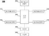
도 1은 본 발명에 따른 무인 항공기용 화물 고정 장치의 예시적인 블록도이다.1 is an exemplary block diagram of a cargo securing apparatus for an unmanned aerial vehicle according to the present invention.
도 1을 참조하면, 본 발명에 따른 무인 항공기용 화물 고정 장치(100)는 제1 화물 접촉부(110), 제2 화물 접촉부(130), 제3 화물 접촉부(150), 제4 화물 접촉부(170), 지지 구조(200) 및 제어부(400)를 포함한다. 또한 본 발명에 따른 무인 항공기용 화물 고정 장치(100)는 수신부(500) 및 무인 항공기 결합부(600)를 더 포함할 수 있다.Referring to FIG. 1, a
제1 화물 접촉부(110), 제2 화물 접촉부(130), 제3 화물 접촉부(150), 제4 화물 접촉부(170)는 박스 형상의 화물의 모서리에 접촉하여 고정 가능하다. 즉 화물을 배송하는 경우에는 박스 형상의 화물의 모서리에 접촉하여 고정할 수 있고 화물을 하역하는 경우에는 박스 형상의 화물의 모서리로부터 이동하여 고정을 해제할 수 있다.The first
제1 화물 접촉부(110), 제2 화물 접촉부(130), 제3 화물 접촉부(150), 제4 화물 접촉부(170)의 상세 구성에 대해서는 도 4 내지 도 5를 참조로 후술한다.The detailed configuration of the first
지지 구조(200)는 제1 화물 접촉부(110), 제2 화물 접촉부(130), 제3 화물 접촉부(150) 및 제4 화물 접촉부(170)를 지지하며, 제1 화물 접촉부(110), 제2 화물 접촉부(130), 제3 화물 접촉부(150) 및 제4 화물 접촉부(170)의 위치를 조절한다.The
도 2는 본 발명에 따른 무인 항공기용 화물 고정 장치의 지지 구조의 예시적인 블록도이다.2 is an exemplary block diagram of a support structure for a cargo securing apparatus for an unmanned aerial vehicle according to the present invention.
도 2를 참조하면, 본 발명에 따른 무인 항공기용 화물 고정 장치(100)의 지지 구조(200)는 제1 지지부(210), 제2 지지부(230), 각도 조절부(250), 제1 위치 조정부(310), 제2 위치 조정부(330), 제3 위치 조정부(350) 및 제4 위치 조정부(370)를 포함한다.2, the supporting
제1 지지부(210)는 제1 화물 접촉부(110) 및 제2 화물 접촉부(130)를 연결하고 제1 화물 접촉부(110) 및 제2 화물 접촉부(130)를 지지한다. 제1 지지부(210)는 예컨대 로드(rod) 형상으로 구성될 수 있다.The
제2 지지부(230)는 제3 화물 접촉부(150) 및 제4 화물 접촉부(170)를 연결하고 제3 화물 접촉부(150) 및 제4 화물 접촉부(170)를 지지한다. 제2 지지부(230)는 제1 지지부(210)와 마찬가지로 예컨대 로드 형상으로 구성될 수 있다. 또한 제2 지지부(230)는 제1 지지부(210)와 마찬가지의 형상 및 크기를 가지는 것이 바람직하다. 제1 지지부(210)의 중심 부분과 제2 지지부(230)의 중심 부분은 예컨대 도 6 내지 도 9에서 도시되듯이 위로부터 보았을 때 같은 부분에 배치되는 것이 바람직하다.The
각도 조절부(250)는 제1 지지부(210) 및 제2 지지부(230)에 연결되며, 위로부터 보았을 때 제1 지지부(210) 및 제2 지지부(230)가 이루는 각도를 조절한다.The
각도 조절부(250)는 특히 정육면체 형상의 화물 또는 직육면체 형상의 화물 등의 화물에 따라서 제1 지지부(210)와 제2 지지부(230)가 이루는 각도를 조절한다.The
예컨대 화물이 정육면체의 박스 형상인 경우에는 제1 지지부(210)와 제2 지지부(230)가 이루는 각도는 90°이다. 또한 화물이 직육면체의 박스 형상인 경우에는 제1 지지부(210)와 제2 지지부(230)가 이루는 각도는 직육면체의 치수, 즉 가로 세로의 비율에 따라서 결정되는 각도를 가진다.For example, when the cargo is a box shape of a cube, the angle between the
각도 조절부(250)는 화물의 치수를 기초로 제1 지지부(210) 및 제2 지지부(230)가 이루는 각도를 조절한다.The
제1 위치 조정부(310)는 제1 화물 접촉부(110) 및 제1 지지부(210)에 접속되며, 제1 화물 접촉부(110)의 위치를 조절한다.The first
즉 제1 위치 조정부(310)는 제1 지지부(210) 내에서 제1 화물 접촉부(110)가 어느 위치에 배치되는 지를 조절한다.That is, the
제2 위치 조정부(330)는 제2 화물 접촉부(130) 및 제1 지지부(210)에 접속되며, 제2 화물 접촉부(130)의 위치를 조절한다.The
제3 위치 조정부(350)는 제3 화물 접촉부(150) 및 제2 지지부(230)에 접속되며, 제3 화물 접촉부(150)의 위치를 조절한다.The third
즉 제3 위치 조정부(350)는 제2 지지부(230) 내에서 제3 화물 접촉부(150)가 어느 위치에 배치되는 지를 조절한다.That is, the
제4 위치 조정부(370)는 제4 화물 접촉부(170) 및 제2 지지부(230)에 접속되며, 제4 화물 접촉부(170)의 위치를 조절한다.The
즉 제3 위치 조정부(350)는 제2 지지부(230) 내에서 제4 화물 접촉부(170)가 어느 위치에 배치되는 지를 조절한다.That is, the
한편 각도 조절부(250), 제1 위치 조정부(310), 제2 위치 조정부(330), 제3 위치 조정부(350) 및 제4 위치 조정부(370)는 서로 연동되어 동작하는 것이 바람직하다. 즉 화물이 정육면체의 박스 형상인 경우 또는 직육면체의 박스 형상인 경우, 각 박스의 상면의 크기 및 치수에 따라서 제1 화물 접촉부(110), 제2 화물 접촉부(130), 제3 화물 접촉부(150) 및 제4 화물 접촉부(170)의 위치가 결정된다. 또한 제1 지지부(210)와 제2 지지부(230)가 이루는 각도도 결정된다.The
따라서 후술하는 제어부(400)는 각도 조절부(250), 제1 위치 조정부(310), 제2 위치 조정부(330), 제3 위치 조정부(350) 및 제4 위치 조정부(370)의 동작을 연동하여 제어할 수 있다.Therefore, the
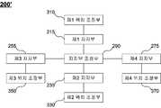
도 3은 본 발명에 따른 무인 항공기용 화물 고정 장치의 지지 구조의 다른 예시적인 블록도이다.3 is another exemplary block diagram of a supporting structure of a cargo holding device for a UAV according to the present invention.
도 3을 참조하면, 본 발명에 따른 무인 항공기용 화물 고정 장치의 지지 구조(200')는 제1 지지부(215), 제2 지지부(235), 제3 지지부(255), 제4 지지부(275), 지지부 조정부(290), 제1 위치 조정부(310), 제2 위치 조정부(330), 제3 위치 조정부(350) 및 제4 위치 조정부(370)를 포함한다.3, the supporting structure 200 'of the cargo holding apparatus for an unmanned aerial vehicle according to the present invention includes a first supporting
제1 지지부(215)는 제1 화물 접촉부(110)에 접속되고 제1 화물 접촉부(110)를 지지한다.The
제2 지지부(235)는 제2 화물 접촉부(130)에 접속되고 제2 화물 접촉부(130)를 지지한다.The
제3 지지부(255)는 제3 화물 접촉부(150)에 접속되고 제3 화물 접촉부(150)를 지지한다.The
제4 지지부(275)는 제4 화물 접촉부(170)에 접속되고 제4 화물 접촉부(170)를 지지한다.The
도 2를 참조로 하는 지지 구조(200)가 두 개의 지지부만을 가지는 것에 비해서, 도 3을 참조로 하는 지지 구조(200')의 구성은 4개의 지지부를 구비하는 점에서 차이가 있다.In contrast to the
지지부 조정부(290)는 제1 지지부(215), 제2 지지부(235), 제3 지지부(255), 제4 지지부(275)의 배치를 조절한다.The supporting
즉 전술한 바와 마찬가지로 화물의 형상이 정육면체 또는 직육면체인 경우에 따라서 제1 지지부(215), 제2 지지부(235), 제3 지지부(255), 제4 지지부(275)의 위치가 조절되어야 한다. 제1 지지부(215), 제2 지지부(235), 제3 지지부(255), 제4 지지부(275)는 서로 연동하여 그 배치가 조절된다.That is, the positions of the
제1 위치 조정부(310) 내지 제4 위치 조정부(370)는 각각 제1 지지부(215) 내지 제4 지지부(275)에 접속되며, 각각 제1 화물 접촉부(110) 내지 제4 화물 접촉부(170)의 위치를 조절한다.The first to fourth
제1 위치 조정부(310) 내지 제4 위치 조정부(370)는 도 2를 참조로 하는 지지 구조(200)에서와 동일하나, 접속되는 대상이 각각 제1 지지부(215) 내지 제4 지지부(275)라는 점에서 차이가 있다.The first
한편 전술한 바와 마찬가지의 이유로 지지부 조정부(290), 제1 위치 조정부(310), 제2 위치 조정부(330), 제3 위치 조정부(350) 및 제4 위치 조정부(370)는 서로 연동되어 동작하는 것이 바람직하다.Meanwhile, for the same reason as described above, the support
따라서 후술하는 제어부(400)는 지지부 조정부(290), 제1 위치 조정부(310), 제2 위치 조정부(330), 제3 위치 조정부(350) 및 제4 위치 조정부(370)의 동작을 연동하여 제어할 수 있다.Therefore, the
다시 도 1을 참조하면, 제어부(400)는 제1 화물 접촉부(110), 제2 화물 접촉부(130), 제3 화물 접촉부(150) 및 제4 화물 접촉부(170)를 박스 형상의 화물을 고정하기 위한 제1 위치 및 박스 형상의 화물을 고정 해제 또는 적재하기 위한 제2 위치 중 어느 하나에 배치되도록 지지 구조(200)를 제어한다.1, the
제1 위치는 예컨대 제1 화물 접촉부(110), 제2 화물 접촉부(130), 제3 화물 접촉부(150) 및 제4 화물 접촉부(170)가 화물을 고정 및 지지할 수 있는 위치이다.The first position is a position where the first
제2 위치는 예컨대 제1 화물 접촉부(110), 제2 화물 접촉부(130), 제3 화물 접촉부(150) 및 제4 화물 접촉부(170)가 고정 및 지지하던 화물을 고정 해제 및 하역할 수 있는 위치이다.The second position can be used to unlock and unload the cargo fixed and supported by the first
전술한 바와 같이 지지 구조(200)는 제1 화물 접촉부(110), 제2 화물 접촉부(130), 제3 화물 접촉부(150) 및 제4 화물 접촉부(170)의 위치를 조절할 수 있다. 이 경우 제1 화물 접촉부(110), 제2 화물 접촉부(130), 제3 화물 접촉부(150) 및 제4 화물 접촉부(170)의 위치는 각각이 개별적으로 조절되는 것보다는 박스 형상의 화물의 치수에 따라서 서로 연동하여 동작하는 것이 바람직하다.As described above, the
제어부(400)는 지지 구조(200)의 동작을 제어하며, 구체적으로 도 2를 참조로 한 구성에서, 각도 조절부(250), 제1 위치 조정부(310), 제2 위치 조정부(330), 제3 위치 조정부(350) 및 제4 위치 조정부(370)의 동작을 연동하여 제어한다.2, the
또한 제어부(400)는 도 3을 참조로 한 지지 구조(200')의 구성에서, 지지부 조정부(290), 제1 위치 조정부(310), 제2 위치 조정부(330), 제3 위치 조정부(350) 및 제4 위치 조정부(370)의 동작을 연동하여 제어한다.3, the
한편 본 발명에 따른 무인 항공기용 화물 고정 장치(100)는 수신부(500)를 더 포함할 수 있다.Meanwhile, the
수신부(500)는 박스 형상의 화물의 치수 정보를 미리 수신한다.The receiving
예컨대 물류 센터에서 화물을 무인 항공기를 이용하여 배송하는 경우, 화물이 무인 항공기의 하단으로 이송한 후 무인 항공기가 예컨대 본 발명에 따른 화물 고정 장치(100)를 이용하여 화물을 적재한다. 화물의 치수가 다른 경우에는 무인 항공기가 화물 고정 장치(100)의 지지 구조(200)를 제어해야 한다. 따라서 지지 구조(200)의 제어에 시간이 소요된다.For example, when the cargo is delivered using the unmanned airplane in the logistics center, the unmanned airplane loads the cargo using the
따라서 화물이 무인 항공기로 이송되기 전에 미리 박스 형상의 화물의 치수 정보를 수신하고, 치수 정보를 기초로 미리 지지 구조(200)를 제어하는 것이 바람직하다.Therefore, it is preferable to receive the dimension information of the box-shaped cargo beforehand before the cargo is transferred to the UAV, and to control the supporting
제어부(400)는 수신부(500)를 통하여 치수 정보를 수신하면, 치수 정보를 기초로 제1 화물 접촉부(110), 제2 화물 접촉부(130), 제3 화물 접촉부(150), 제4 화물 접촉부(170)를 제2 위치로 배치하고, 박스 형상의 화물이 이송되면 제1 화물 접촉부(110), 제2 화물 접촉부(130), 제3 화물 접촉부(150), 제4 화물 접촉부(170)를 제1 위치로 배치하여 화물을 적재하고, 예컨대 무인 항공기가 배송 지점에 도착하여 박스 형상의 화물을 하역하는 경우 제1 화물 접촉부(110), 제2 화물 접촉부(130), 제3 화물 접촉부(150), 제4 화물 접촉부(170)를 제2 위치로 배치하도록 지지 구조(200)를 제어할 수 있다. 한편 도 3의 지지 구조(200')의 경우에서도 마찬가지이다.The
한편 전술한 제1 위치 및 제2 위치는 화물에 따라서 동적으로 결정될 수 있다.On the other hand, the first position and the second position described above can be determined dynamically according to the cargo.
즉 제어부(400)는 수신부(500)를 통하여 치수 정보를 수신하면, 치수 정보를 기초로 제1 위치 및 제2 위치를 동적으로 결정한다.That is, when the
따라서 제어부(400)는 다양한 규격의 박스 형태의 화물이 이송되더라도 신속하게 제1 위치 및 제2 위치를 동적으로 결정할 수 있다.Therefore, the
한편 본 발명에 따른 무인 항공기용 화물 고정 장치(100)는 무인 항공기 결합부(600)를 더 포함할 수 있다.Meanwhile, the
무인 항공기 결합부(600)는 본 발명에 따른 무인 항공기용 화물 고정 장치(100)를 무인 항공기에 탈착하기 위한 구조로서, 예컨대 홈을 구비하여 무인 항공기에 볼트와 너트를 이용하여 고정하는 구성을 가질 수 있다. 또는 다른 결합 구조도 가능하다.The unmanned
이하 본 발명에 따른 무인 항공기용 화물 고정 장치(100)의 제1 내지 제4 화물 접촉부(110 내지 170)의 예시적인 구성을 도 4 및 도 5를 참조로 설명한다. 도 4 및 도 5는 예시적으로 제1 화물 접촉부(110)에 대해서 도시하지만, 제2 내지 제4 화물 접촉부(130 내지 170) 역시 마찬가지의 구성을 가진다.Hereinafter, an exemplary configuration of the first to fourth
도 4는 본 발명에 따른 무인 항공기용 화물 고정 장치의 화물 접촉부의 예시적인 구성을 나타내는 도면이다.4 is a view showing an exemplary configuration of a cargo contacting portion of a cargo holding device for a UAV according to the present invention.
도 4를 참조하면, 제1 화물 접촉부(110)는 박스 형상의 화물의 상면의 모서리에 접촉 가능한 3개의 접촉면(110a, 110b, 110c)을 구비한다.Referring to FIG. 4, the first
예컨대 접촉면(110a)은 박스 형상의 화물의 상면에 접촉한다. 또한 접촉면(110b, 110c)은 박스 형상의 화물의 상면의 모서리의 양 측면에 접촉한다.For example, the
도 4의 예시적인 구성에서 박스 형상의 화물의 4개의 모서리에서 상면 및 각 측면들에 제1 내지 제4 화물 접촉부(110 내지 170)가 접촉한다. 따라서 제1 위치에 제1 내지 제4 화물 접촉부(110 내지 170)가 배치되는 경우, 마찰력에 의해서 박스 형상의 화물이 지지된다.In the exemplary configuration of Fig. 4, the first to
또한 제2 위치에 제1 내지 제4 화물 접촉부(110 내지 170)가 배치되는 경우, 마찰력이 해제되므로 중력에 의해서 박스 형상의 화물이 낙하한다. 즉 하역된다.Further, when the first to fourth
따라서 무인 항공기가 화물을 고정하거나 하역하는 것이 가능하다.It is therefore possible for an unmanned aircraft to lock or unload cargo.
도 5는 본 발명에 따른 무인 항공기용 화물 고정 장치의 화물 접촉부의 다른 예시적인 구성을 나타내는 도면이다.5 is a view showing another exemplary configuration of a cargo contacting portion of a cargo holding device for a UAV according to the present invention.
도 5를 참조하면, 제1 화물 접촉부(110)는 박스 형상의 화물의 하면의 모서리에 접촉 가능한 3개의 접촉면(110d, 110e, 110f)과 연결부(110g)를 구비한다.Referring to FIG. 5, the first
예컨대 접촉면(110d)은 박스 형상의 화물의 하면에 접촉한다. 또한 접촉면(110e, 110f)은 박스 형상의 화물의 하면의 모서리의 양 측면에 접촉한다. 연결부(110g)는 3개의 접촉면(110d, 110e, 110f)을 지지 구조(200)에 접속한다. 바람직하게는 연결부(110g)는 제어부(400)의 제어에 의해서 높이가 조절될 수 있다. 즉 연결부(110d)의 높이를 조절하는 것에 의해서 무인 항공기에 의해서 배송될 박스 형상의 화물의 크기에 대한 제한을 최소화할 수 있다.For example, the
도 5의 예시적인 구성에서 박스 형상의 화물의 하면의 4개의 모서리에서 하면 및 각 측면들에 제1 내지 제4 화물 접촉부(110 내지 170)가 접촉한다. 따라서 제1 위치에 제1 내지 제4 화물 접촉부(110 내지 170)가 배치되는 경우, 제1 내지 제4 화물 접촉부(110 내지 170)에 의해서 박스 형상의 화물이 지지된다.In the exemplary configuration of Fig. 5, the first to fourth
또한 제2 위치에 제1 내지 제4 화물 접촉부(110 내지 170)가 배치되는 경우, 지지가 해제되므로 중력에 의해서 박스 형상의 화물이 낙하한다. 즉 하역된다.When the first to fourth
따라서 무인 항공기가 화물을 고정하거나 하역하는 것이 가능하다.It is therefore possible for an unmanned aircraft to lock or unload cargo.
도 6은 본 발명에 따른 무인 항공기용 화물 고정 장치의 예시적인 구성을 나타내는 도면이다.6 is a view showing an exemplary configuration of a cargo securing apparatus for an unmanned aerial vehicle according to the present invention.
도 6을 참조하면, 제1 지지부(210), 제2 지지부(230) 및 각도 조절부(250)를 구비하는 도 2를 참조로 한 지지 구조(200)를 포함하는 무인 항공기용 화물 고정 장치(100)가 개시되나, 도 3을 참조로 한 지지 구조(200')를 포함하는 무인 항공기용 화물 고정 장치(100)의 구성 역시 제1 지지부(210), 제2 지지부(230) 및 각도 조절부(250)가 지지부의 개수 및 지지부 조정부(290)로 대체되는 것을 제외하면 동일하다.Referring to FIG. 6, a cargo holding device for a unmanned aerial vehicle (hereinafter referred to as a cargo holding device) 210 including a supporting
각도 조절부(250)는 예컨대 서보 모터 등의 모터를 이용하여 구현될 수 있다.The
제1 위치 조정부(310), 제2 위치 조정부(330), 제3 위치 조정부(350) 및 제4 위치 조정부(370)는 예컨대 볼 스크류 회전 모터를 이용하여 구현할 수 있다.The first
도 7 및 도 8은 본 발명에 따른 무인 항공기용 화물 고정 장치의 예시적인 구성에 있어서 제1 지지부 및 제2 지지부가 이루는 각도의 조절을 예시적으로 나타내는 도면이다.FIG. 7 and FIG. 8 are views showing an exemplary adjustment of the angle between the first support portion and the second support portion in the exemplary configuration of the cargo holding device for a UAV according to the present invention.
제1 지지부(210)와 제2 지지부(230)가 이루는 각도는 전술하듯이 박스의 형상이 정육면체인지 또는 직육면체인지에 따라서 달라지며, 직육면체에서도 가로 세로의 비율에 따라서 달라진다.The angle formed by the
예컨대 도 7은 박스의 형상이 직육면체인 경우를 도시한다.7 shows a case where the shape of the box is a rectangular parallelepiped.
한편 박스의 형상이 정육면체인 경우라면, 각도 조절부(250)는 제1 지지부(210)와 제2 지지부(230)가 이루는 각도를 도 8에 도시되듯이 90°로 조절한다.On the other hand, if the shape of the box is a cube, the
도 9는 본 발명에 따른 무인 항공기용 화물 고정 장치의 예시적인 구성에 있어서 화물 접촉부의 위치 조절을 예시적으로 나타내는 도면이다.FIG. 9 is an exemplary view illustrating the position adjustment of the cargo contacting portion in the exemplary configuration of the cargo holding device for a UAV according to the present invention.
예컨대 박스의 형상이 정육면체인 경우라도, 박스의 크기는 다를 수 있다.For example, even when the shape of the box is a cube, the size of the box may be different.
따라서 도 9를 참조하면, 제1 위치 조정부(310), 제2 위치 조정부(330), 제3 위치 조정부(350) 및 제4 위치 조정부(370)에 의해서 제1 내지 제4 화물 접촉부(110 내지 170)의 위치가 조절된다.Referring to FIG. 9, the first to fourth
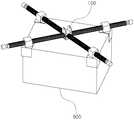
도 10은 본 발명에 따른 무인 항공기용 화물 고정 장치에 박스 형상의 화물이 고정되는 예를 나타내는 도면이다.10 is a view showing an example in which a box-like cargo is fixed to a cargo fixing apparatus for a UAV according to the present invention.
도 10을 참조하면, 박스 형상의 화물의 상면의 4개의 모서리가 무인 항공기용 화물 고정 장치(100)의 제1 내지 제4 화물 접촉부(110 내지 170)에 의해서 접촉하여 마찰력에 의해서 고정된다.10, the four corners of the upper surface of the box-shaped cargo are held in contact with each other by the first to fourth
한편 예컨대 도 5를 참조로 한 제1 내지 제4 화물 접촉부(110 내지 170)를 구비하는 무인 항공기용 화물 고정 장치(100)의 경우에는, 박스 형상의 화물의 하면의 4개의 모서리가 무인 항공기용 화물 고정 장치(100)의 제1 내지 제4 화물 접촉부(110 내지 170)에 의해서 지지될 수 있다.For example, in the case of the
이상에서 설명한 바와 같이 본 발명에 따르면 무인 항공기에 의해서 배송될 박스 형상의 화물의 크기에 대한 제한을 최소화하는 무인 항공기용 화물 고정 장치를 제공할 수 있다.As described above, according to the present invention, it is possible to provide a cargo securing apparatus for an unmanned aerial vehicle that minimizes the limitation on the size of a box-shaped cargo to be delivered by an unmanned aerial vehicle.
특히 박스 형상의 화물의 치수 정보를 미리 수신한 후, 박스 형상의 화물을 고정하기 위한 제1 위치 및 박스 형상의 화물을 고정 해제 또는 적재하기 위한 제2 위치를 동적으로 결정하여 화물 접촉부를 제1 위치 및 제2 위치에 신속하게 배치할 수 있으므로, 다양한 크기의 박스 형상의 화물을 운송하는 경우에도 신속하게 화물을 무인 항공기에 적재 및 하역할 수 있다.After the size information of the box-shaped cargo has been received in advance, a first position for fixing the box-like cargo and a second position for docking or loading the cargo in a box shape are dynamically determined, Position and the second position, so that the cargo can be quickly loaded and unloaded on the UAV even when carrying various types of box-shaped cargoes.
도 11은 본 발명에 따른 무인 항공기의 예시적인 구성을 나타내는 도면이다.11 is a diagram showing an exemplary configuration of an unmanned aerial vehicle according to the present invention.
도 11을 참조하면, 무인 항공기(1000)는 본체(1100)와 본 발명에 따른 무인 항공기용 화물 고정 장치(100)를 포함한다.Referring to FIG. 11, the
본 발명에 따른 무인 항공기의 구성은 도 1 내지 도 10을 참조로 한 본 발명에 따른 무인 항공기용 화물 고정 장치(100)가 무인 항공기에 일체형으로 장착된 것을 제외하면 도 1 내지 도 10을 참조로 한 본 발명에 따른 무인 항공기용 화물 고정 장치(100)와 동일하므로 상세한 설명을 생략한다.The construction of the UAV according to the present invention will now be described with reference to FIGS. 1 to 10, except that the
또한 본 발명에 따른 무인 항공기의 구성은 예시적인 것일 뿐이며, 예컨대 회전 날개가 8개인 옥타드론 등 다양한 형태를 가질 수 있다.The configuration of the unmanned aerial vehicle according to the present invention is merely an example, and may have various forms such as an octadron having eight rotary blades.
이상에서 설명한 바와 같이 본 발명에 따른 무인 항공기에 따르면, 배송될 박스 형상의 화물의 크기에 대한 제한을 최소화할 수 있다. 특히 박스 형상의 화물의 치수 정보를 미리 수신한 후, 박스 형상의 화물을 고정하기 위한 제1 위치 및 박스 형상의 화물을 고정 해제 또는 적재하기 위한 제2 위치를 동적으로 결정하여 화물 접촉부를 제1 위치 및 제2 위치에 신속하게 배치할 수 있으므로, 다양한 크기의 박스 형상의 화물을 운송하는 경우에도 신속하게 화물을 적재 및 하역할 수 있다.As described above, according to the unmanned aerial vehicle according to the present invention, the limitation on the size of the box-shaped cargo to be delivered can be minimized. After the size information of the box-shaped cargo has been received in advance, a first position for fixing the box-like cargo and a second position for docking or loading the cargo in a box shape are dynamically determined, Position and the second position, it is possible to quickly load and unload the cargo even when the cargo of the box-shaped cargo of various sizes is transported.
비록 본 발명의 구성이 구체적으로 설명되었지만 이는 단지 본 발명을 예시적으로 설명한 것에 불과한 것으로, 본 발명이 속하는 기술분야에서 통상의 지식을 가지는 자라면 본 발명의 본질적인 특성에서 벗어나지 않는 범위 내에서 다양한 변형이 가능할 것이다.Although the present invention has been described in detail, it should be understood that the present invention is not limited thereto. Those skilled in the art will appreciate that various modifications may be made without departing from the essential characteristics of the present invention. Will be possible.
따라서 본 명세서에 개시된 실시예들은 본 발명을 한정하기 위한 것이 아니라 설명하기 위한 것이고, 이러한 실시예에 의하여 본 발명의 사상과 범위가 한정되는 것은 아니다. 본 발명의 범위는 아래의 청구범위에 의해 해석되어야 하며, 그와 동등한 범위 내에 있는 모든 기술은 본 발명의 권리범위에 포함되는 것으로 해석되어야 할 것이다.Therefore, the embodiments disclosed in the present specification are intended to illustrate rather than limit the present invention, and the scope and spirit of the present invention are not limited by these embodiments. The scope of the present invention should be construed according to the following claims, and all the techniques within the scope of equivalents should be construed as being included in the scope of the present invention.
본 발명에 따르면 무인 항공기에 의해서 배송될 박스 형상의 화물의 크기에 대한 제한을 최소화하는 무인 항공기용 화물 고정 장치 및 무인 항공기를 제공할 수 있다.According to the present invention, it is possible to provide a cargo holding device for a UAV and an unmanned airplane that minimizes the limitation on the size of a box-shaped cargo to be delivered by the UAV.
특히 박스 형상의 화물의 치수 정보를 미리 수신한 후, 박스 형상의 화물을 고정하기 위한 제1 위치 및 박스 형상의 화물을 고정 해제 또는 적재하기 위한 제2 위치를 동적으로 결정하여 화물 접촉부를 제1 위치 및 제2 위치에 신속하게 배치할 수 있으므로, 다양한 크기의 박스 형상의 화물을 운송하는 경우에도 신속하게 화물을 무인 항공기에 적재 및 하역할 수 있다.After the size information of the box-shaped cargo has been received in advance, a first position for fixing the box-like cargo and a second position for docking or loading the cargo in a box shape are dynamically determined, Position and the second position, so that the cargo can be quickly loaded and unloaded on the UAV even when carrying various types of box-shaped cargoes.
100: 무인 항공기용 화물 고정 장치
110: 제1 화물 접촉부110a 내지 110f: 접촉면
110g: 연결부130: 제2 화물 접촉부
150: 제3 화물 접촉부170: 제4 화물 접촉부
200: 지지 구조210: 제1 지지부
215: 제1 지지부230: 제2 지지부
235: 제2 지지부250: 각도 조절부
255: 제3 지지부275: 제5 지지부
290: 지지부 조정부310: 제1 위치 조정부
330: 제2 위치 조정부350: 제3 위치 조정부
370: 제4 위치 조정부400: 제어부
500: 수신부600: 무인 항공기 결합부
1000: 무인 항공기100: Cargo hold device for unmanned aircraft
110: first
110g: connection part 130: second cargo contact part
150: third cargo contacting portion 170: fourth cargo contacting portion
200: supporting structure 210: first supporting part
215: first support part 230: second support part
235: second supporting part 250: angle adjusting part
255: third support portion 275: fifth support portion
290: support part adjustment part 310: first position adjustment part
330: second position adjustment unit 350: third position adjustment unit
370: fourth position adjustment unit 400:
500: Receiving unit 600: Unmanned aerial vehicle coupling unit
1000: Unmanned aircraft
Claims (19)
Translated fromKorean상기 제1 내지 제4 화물 접촉부를 지지하며, 상기 제1 내지 제4 화물 접촉부의 위치를 조절하는 지지 구조; 및
상기 제1 내지 제4 화물 접촉부를 상기 박스 형상의 화물을 고정하기 위한 제1 위치 및 상기 박스 형상의 화물을 고정 해제 또는 적재하기 위한 제2 위치 중 어느 하나에 배치되도록 상기 지지 구조를 제어하는 제어부
를 포함하고,
상기 지지 구조는,
상기 제1 화물 접촉부 및 상기 제2 화물 접촉부를 연결 및 지지하는 제1 지지부;
상기 제3 화물 접촉부 및 상기 제4 화물 접촉부를 연결 및 지지하는 제2 지지부;
상기 제1 지지부 및 상기 제2 지지부에 연결되며, 위로부터 보았을 때 상기 제1 지지부와 상기 제2 지지부가 이루는 각도를 조절하는 각도 조절부;
상기 제1 화물 접촉부 및 상기 제1 지지부에 접속되며, 상기 제1 화물 접촉부의 위치를 조절하는 제1 위치 조정부;
상기 제2 화물 접촉부 및 상기 제1 지지부에 접속되며, 상기 제2 화물 접촉부의 위치를 조절하는 제2 위치 조정부;
상기 제3 화물 접촉부 및 상기 제2 지지부에 접속되며, 상기 제3 화물 접촉부의 위치를 조절하는 제3 위치 조정부; 및
상기 제4 화물 접촉부 및 상기 제2 지지부에 접속되며, 상기 제4 화물 접촉부의 위치를 조절하는 제4 위치 조정부
를 포함하는 것이고,
상기 제어부는 상기 각도 조절부 및 상기 제1 내지 제4 위치 조정부의 동작을 서로 연동하여 제어하는 것인 무인 항공기용 화물 고정 장치.A first cargo contacting portion, a third cargo contacting portion, and a fourth cargo contacting portion that are capable of being fixed in contact with the edges of the box-shaped cargo;
A supporting structure for supporting the first to fourth cargo contacting portions and adjusting the positions of the first to fourth cargo contacting portions; And
And a control section for controlling the support structure so that the first to fourth cargo contacting portions are disposed in any one of a first position for fixing the box-like cargo and a second position for releasing or loading the box-
Lt; / RTI >
The support structure includes:
A first support portion for connecting and supporting the first and second cargo contact portions;
A second support portion for connecting and supporting the third cargo contacting portion and the fourth cargo contacting portion;
An angle adjusting unit connected to the first supporting unit and the second supporting unit and adjusting an angle formed by the first supporting unit and the second supporting unit when viewed from above;
A first position adjuster connected to the first cargo contacting portion and the first supporting portion and adjusting a position of the first cargo contacting portion;
A second position adjuster connected to the second cargo contacting portion and the first supporting portion and adjusting the position of the second cargo contacting portion;
A third position adjuster connected to the third cargo contacting portion and the second supporting portion and adjusting a position of the third cargo contacting portion; And
A fourth position adjuster connected to the fourth cargo contacting portion and the second supporting portion for adjusting the position of the fourth cargo contacting portion,
, ≪ / RTI >
Wherein the controller controls the operations of the angle adjusting unit and the first to fourth position adjusting units in association with each other.
상기 제1 내지 제4 화물 접촉부를 지지하며, 상기 제1 내지 제4 화물 접촉부의 위치를 조절하는 지지 구조; 및
상기 제1 내지 제4 화물 접촉부를 상기 박스 형상의 화물을 고정하기 위한 제1 위치 및 상기 박스 형상의 화물을 고정 해제 또는 적재하기 위한 제2 위치 중 어느 하나에 배치되도록 상기 지지 구조를 제어하는 제어부
를 포함하고,
상기 지지 구조는,
각각 상기 제1 화물 접촉부 내지 상기 제4 화물 접촉부 중 대응되는 것과 접속되고 지지하는 제1 내지 제4 지지부;
상기 제1 내지 제4 지지부의 배치를 조정하는 지지부 조정부;
상기 제1 화물 접촉부 및 상기 제1 지지부에 접속되며, 상기 제1 화물 접촉부의 위치를 조절하는 제1 위치 조정부;
상기 제2 화물 접촉부 및 상기 제2 지지부에 접속되며, 상기 제2 화물 접촉부의 위치를 조절하는 제2 위치 조정부;
상기 제3 화물 접촉부 및 상기 제3 지지부에 접속되며, 상기 제3 화물 접촉부의 위치를 조절하는 제3 위치 조정부; 및
상기 제4 화물 접촉부 및 상기 제4 지지부에 접속되며, 상기 제4 화물 접촉부의 위치를 조절하는 제4 위치 조정부
를 포함하는 것이고,
상기 제어부는 상기 지지부 조정부 및 상기 제1 내지 제4 위치 조정부의 동작을 서로 연동하여 제어하는 것인 무인 항공기용 화물 고정 장치.A first cargo contacting portion, a third cargo contacting portion, and a fourth cargo contacting portion that are capable of being fixed in contact with the edges of the box-shaped cargo;
A supporting structure for supporting the first to fourth cargo contacting portions and adjusting the positions of the first to fourth cargo contacting portions; And
And a control section for controlling the support structure so that the first to fourth cargo contacting portions are disposed at any one of a first position for fixing the box-like cargo and a second position for releasing or loading the box-
Lt; / RTI >
The support structure includes:
First to fourth supporting portions connected to and supporting the corresponding ones of the first to fourth cargo contacting portions, respectively;
A support portion adjuster for adjusting the arrangement of the first to fourth support portions;
A first position adjuster connected to the first cargo contacting portion and the first supporting portion and adjusting a position of the first cargo contacting portion;
A second position adjuster connected to the second cargo contacting portion and the second supporting portion for adjusting a position of the second cargo contacting portion;
A third position adjuster connected to the third cargo contacting portion and the third supporting portion for adjusting a position of the third cargo contacting portion; And
A fourth position adjuster connected to the fourth cargo contacting portion and the fourth supporting portion for adjusting the position of the fourth cargo contacting portion,
, ≪ / RTI >
Wherein the control unit controls the operations of the support unit adjusting unit and the first to fourth position adjusting units in association with each other.
상기 제1 화물 접촉부, 제2 화물 접촉부, 제3 화물 접촉부 및 제4 화물 접촉부 각각은 상기 제1 위치에서 상기 화물의 3개 면에 접촉하도록 구성되는 것인 무인 항공기용 화물 고정 장치.3. The method according to claim 1 or 2,
Wherein each of the first cargo contacting portion, the second cargo contacting portion, the third cargo contacting portion, and the fourth cargo contacting portion is configured to contact three sides of the cargo at the first position.
상기 제1 지지부의 중심 부분과 상기 제2 지지부의 중심 부분은 위로부터 보았을 때 같은 부분에 배치되는 것인 무인 항공기용 화물 고정 장치.The method according to claim 1,
Wherein a center portion of the first support portion and a center portion of the second support portion are disposed at the same portion when viewed from above.
상기 박스 형상의 화물의 치수 정보를 미리 수신하는 수신부를 더 포함하고,
상기 제어부는
상기 수신부로부터 상기 치수 정보를 수신하면, 상기 치수 정보를 기초로 상기 제1 내지 제4 화물 접촉부를 상기 제2 위치로 배치하고 상기 박스 형상의 화물이 이송되면 상기 제1 내지 제4 화물 접촉부를 상기 제1 위치로 배치하고, 상기 박스 형상의 화물을 하역하는 경우 상기 제1 내지 제4 화물 접촉부를 상기 제2 위치로 배치하도록 상기 지지 구조를 제어하는 것인 무인 항공기용 화물 고정 장치.3. The method according to claim 1 or 2,
Further comprising a receiving unit for receiving dimension information of the box-like cargo in advance,
The control unit
Wherein when the dimension information is received from the receiving unit, the first to fourth cargo contacting portions are arranged at the second position based on the dimension information, and when the box-shaped cargo is transferred, And wherein the support structure is arranged to arrange the first to fourth cargo contacting portions in the second position when the box-shaped cargo is unloaded.
상기 제어부는 상기 치수 정보를 기초로 상기 제1 위치 및 상기 제2 위치를 동적으로 결정하는 것인 무인 항공기용 화물 고정 장치.The method according to claim 6,
Wherein the control unit dynamically determines the first position and the second position based on the dimension information.
상기 제1 화물 접촉부, 제2 화물 접촉부, 제3 화물 접촉부 및 제4 화물 접촉부는 상기 박스 형상의 화물의 윗부분의 4개의 모서리에 각각 접촉하는 것인 무인 항공기용 화물 고정 장치.3. The method according to claim 1 or 2,
Wherein the first cargo contacting portion, the second cargo contacting portion, the third cargo contacting portion and the fourth cargo contacting portion are in contact with four corners of the upper portion of the box-like cargo, respectively.
상기 제1 화물 접촉부, 제2 화물 접촉부, 제3 화물 접촉부 및 제4 화물 접촉부는 상기 박스 형상의 화물의 아랫부분의 4개의 모서리에 각각 접촉하는 것인 무인 항공기용 화물 고정 장치.3. The method according to claim 1 or 2,
Wherein the first cargo contacting portion, the second cargo contacting portion, the third cargo contacting portion, and the fourth cargo contacting portion are in contact with four corners of the bottom portion of the box-like cargo, respectively.
상기 지지 구조에 연결되며, 무인 항공기에 탈착 가능한 무인 항공기 결합부
를 더 포함하는 무인 항공기용 화물 고정 장치.3. The method according to claim 1 or 2,
And a control unit connected to the support structure and detachable to the unmanned airplane,
Further comprising: a load lock mechanism for unmanned aircraft.
박스 형상의 화물의 모서리에 접촉하여 고정 가능한 제1 화물 접촉부, 제2 화물 접촉부, 제3 화물 접촉부 및 제4 화물 접촉부;
상기 본체에 설치되고 상기 제1 내지 제4 화물 접촉부를 지지하며, 상기 제1 내지 제4 화물 접촉부의 위치를 조절하는 지지 구조; 및
상기 제1 내지 제4 화물 접촉부를 상기 박스 형상의 화물을 고정하기 위한 제1 위치 및 상기 박스 형상의 화물을 고정 해제 또는 적재하기 위한 제2 위치 중 어느 하나에 배치되도록 상기 지지 구조를 제어하는 제어부
를 포함하고,
상기 지지 구조는,
상기 제1 화물 접촉부 및 상기 제2 화물 접촉부를 연결 및 지지하는 제1 지지부;
상기 제3 화물 접촉부 및 상기 제4 화물 접촉부를 연결 및 지지하는 제2 지지부;
상기 제1 지지부 및 상기 제2 지지부에 연결되며, 위로부터 보았을 때 상기 제1 지지부와 상기 제2 지지부가 이루는 각도를 조절하는 각도 조절부;
상기 제1 화물 접촉부 및 상기 제1 지지부에 접속되며, 상기 제1 화물 접촉부의 위치를 조절하는 제1 위치 조정부;
상기 제2 화물 접촉부 및 상기 제1 지지부에 접속되며, 상기 제2 화물 접촉부의 위치를 조절하는 제2 위치 조정부;
상기 제3 화물 접촉부 및 상기 제2 지지부에 접속되며, 상기 제3 화물 접촉부의 위치를 조절하는 제3 위치 조정부; 및
상기 제4 화물 접촉부 및 상기 제2 지지부에 접속되며, 상기 제4 화물 접촉부의 위치를 조절하는 제4 위치 조정부
를 포함하는 것이고,
상기 제어부는 상기 각도 조절부 및 상기 제1 내지 제4 위치 조정부의 동작을 서로 연동하여 제어하는 것인 무인 항공기.main body;
A first cargo contacting portion, a third cargo contacting portion, and a fourth cargo contacting portion that are capable of being fixed in contact with the edges of the box-shaped cargo;
A support structure installed on the main body and supporting the first to fourth cargo contact portions and adjusting positions of the first to fourth cargo contact portions; And
And a control section for controlling the support structure so that the first to fourth cargo contacting portions are disposed at any one of a first position for fixing the box-like cargo and a second position for releasing or loading the box-
Lt; / RTI >
The support structure includes:
A first support portion for connecting and supporting the first and second cargo contact portions;
A second support portion for connecting and supporting the third cargo contacting portion and the fourth cargo contacting portion;
An angle adjusting unit connected to the first supporting unit and the second supporting unit and adjusting an angle formed by the first supporting unit and the second supporting unit when viewed from above;
A first position adjuster connected to the first cargo contacting portion and the first supporting portion and adjusting a position of the first cargo contacting portion;
A second position adjuster connected to the second cargo contacting portion and the first supporting portion and adjusting the position of the second cargo contacting portion;
A third position adjuster connected to the third cargo contacting portion and the second supporting portion and adjusting a position of the third cargo contacting portion; And
A fourth position adjuster connected to the fourth cargo contacting portion and the second supporting portion for adjusting the position of the fourth cargo contacting portion,
, ≪ / RTI >
Wherein the controller controls the operations of the angle adjusting unit and the first to fourth position adjusting units in association with each other.
박스 형상의 화물의 모서리에 접촉하여 고정 가능한 제1 화물 접촉부, 제2 화물 접촉부, 제3 화물 접촉부 및 제4 화물 접촉부;
상기 본체에 설치되고 상기 제1 내지 제4 화물 접촉부를 지지하며, 상기 제1 내지 제4 화물 접촉부의 위치를 조절하는 지지 구조; 및
상기 제1 내지 제4 화물 접촉부를 상기 박스 형상의 화물을 고정하기 위한 제1 위치 및 상기 박스 형상의 화물을 고정 해제 또는 적재하기 위한 제2 위치 중 어느 하나에 배치되도록 상기 지지 구조를 제어하는 제어부
를 포함하고,
상기 지지 구조는,
각각 상기 제1 화물 접촉부 내지 상기 제4 화물 접촉부 중 대응되는 것과 접속되고 지지하는 제1 내지 제4 지지부;
상기 제1 내지 제4 지지부의 배치를 조정하는 지지부 조정부;
상기 제1 화물 접촉부 및 상기 제1 지지부에 접속되며, 상기 제1 화물 접촉부의 위치를 조절하는 제1 위치 조정부;
상기 제2 화물 접촉부 및 상기 제2 지지부에 접속되며, 상기 제2 화물 접촉부의 위치를 조절하는 제2 위치 조정부;
상기 제3 화물 접촉부 및 상기 제3 지지부에 접속되며, 상기 제3 화물 접촉부의 위치를 조절하는 제3 위치 조정부; 및
상기 제4 화물 접촉부 및 상기 제4 지지부에 접속되며, 상기 제4 화물 접촉부의 위치를 조절하는 제4 위치 조정부
를 포함하는 것이고,
상기 제어부는 상기 지지부 조정부 및 상기 제1 내지 제4 위치 조정부의 동작을 서로 연동하여 제어하는 것인 무인 항공기.main body;
A first cargo contacting portion, a third cargo contacting portion, and a fourth cargo contacting portion that are capable of being fixed in contact with the edges of the box-shaped cargo;
A support structure installed on the main body and supporting the first to fourth cargo contact portions and adjusting positions of the first to fourth cargo contact portions; And
And a control section for controlling the support structure so that the first to fourth cargo contacting portions are disposed at any one of a first position for fixing the box-like cargo and a second position for releasing or loading the box-
Lt; / RTI >
The support structure includes:
First to fourth supporting portions connected to and supporting the corresponding ones of the first to fourth cargo contacting portions, respectively;
A support portion adjuster for adjusting the arrangement of the first to fourth support portions;
A first position adjuster connected to the first cargo contacting portion and the first supporting portion and adjusting a position of the first cargo contacting portion;
A second position adjuster connected to the second cargo contacting portion and the second supporting portion for adjusting a position of the second cargo contacting portion;
A third position adjuster connected to the third cargo contacting portion and the third supporting portion for adjusting a position of the third cargo contacting portion; And
A fourth position adjuster connected to the fourth cargo contacting portion and the fourth supporting portion for adjusting the position of the fourth cargo contacting portion,
, ≪ / RTI >
Wherein the control unit controls the operations of the support unit adjustment unit and the first to fourth position adjustment units in association with each other.
상기 제1 화물 접촉부, 제2 화물 접촉부, 제3 화물 접촉부 및 제4 화물 접촉부 각각은 상기 제1 위치에서 상기 화물의 3개 면에 접촉하도록 구성되는 것인 무인 항공기.13. The method according to claim 11 or 12,
Wherein each of the first cargo contacting portion, the second cargo contacting portion, the third cargo contacting portion and the fourth cargo contacting portion is configured to contact three sides of the cargo in the first position.
상기 제1 지지부의 중심 부분과 상기 제2 지지부의 중심 부분은 위로부터 보았을 때 같은 부분에 배치되는 것인 무인 항공기.12. The method of claim 11,
Wherein the center portion of the first support portion and the center portion of the second support portion are disposed at the same portion when viewed from above.
상기 박스 형상의 화물의 치수 정보를 미리 수신하는 수신부를 더 포함하고,
상기 제어부는
상기 수신부로부터 상기 치수 정보를 수신하면, 상기 치수 정보를 기초로 상기 제1 내지 제4 화물 접촉부를 상기 제2 위치로 배치하고 상기 박스 형상의 화물이 이송되면 상기 제1 내지 제4 화물 접촉부를 상기 제1 위치로 배치하고, 상기 박스 형상의 화물을 하역하는 경우 상기 제1 내지 제4 화물 접촉부를 상기 제2 위치로 배치하도록 상기 지지 구조를 제어하는 것인 무인 항공기.13. The method according to claim 11 or 12,
Further comprising a receiving unit for receiving dimension information of the box-like cargo in advance,
The control unit
Wherein when the dimension information is received from the receiving unit, the first to fourth cargo contacting portions are arranged at the second position based on the dimension information, and when the box-shaped cargo is transferred, Wherein the control unit controls the support structure to arrange the first to fourth cargo contact portions in the second position when the box-shaped cargo is unloaded.
상기 제어부는 상기 치수 정보를 기초로 상기 제1 위치 및 상기 제2 위치를 동적으로 결정하는 것인 무인 항공기.17. The method of claim 16,
Wherein the control unit dynamically determines the first position and the second position based on the dimension information.
상기 제1 화물 접촉부, 제2 화물 접촉부, 제3 화물 접촉부 및 제4 화물 접촉부는 상기 박스 형상의 화물의 윗부분의 4개의 모서리에 각각 접촉하는 것인 무인 항공기.13. The method according to claim 11 or 12,
Wherein the first cargo contacting portion, the second cargo contacting portion, the third cargo contacting portion, and the fourth cargo contacting portion respectively contact the four corners of the upper portion of the box-like cargo.
상기 제1 화물 접촉부, 제2 화물 접촉부, 제3 화물 접촉부 및 제4 화물 접촉부는 상기 박스 형상의 화물의 아랫부분의 4개의 모서리에 각각 접촉하는 것인 무인 항공기.13. The method according to claim 11 or 12,
Wherein the first cargo contacting portion, the second cargo contacting portion, the third cargo contacting portion, and the fourth cargo contacting portion respectively contact four corners of a lower portion of the box-like cargo.
Priority Applications (1)
| Application Number | Priority Date | Filing Date | Title |
|---|---|---|---|
| KR1020150181495AKR101682574B1 (en) | 2015-12-18 | 2015-12-18 | Engaging apparatus of unmanned aerial vehicle and unmanned aerial vehicle |
Applications Claiming Priority (1)
| Application Number | Priority Date | Filing Date | Title |
|---|---|---|---|
| KR1020150181495AKR101682574B1 (en) | 2015-12-18 | 2015-12-18 | Engaging apparatus of unmanned aerial vehicle and unmanned aerial vehicle |
Publications (1)
| Publication Number | Publication Date |
|---|---|
| KR101682574B1true KR101682574B1 (en) | 2016-12-05 |
Family
ID=57576054
Family Applications (1)
| Application Number | Title | Priority Date | Filing Date |
|---|---|---|---|
| KR1020150181495AExpired - Fee RelatedKR101682574B1 (en) | 2015-12-18 | 2015-12-18 | Engaging apparatus of unmanned aerial vehicle and unmanned aerial vehicle |
Country Status (1)
| Country | Link |
|---|---|
| KR (1) | KR101682574B1 (en) |
Cited By (12)
| Publication number | Priority date | Publication date | Assignee | Title |
|---|---|---|---|---|
| CN107089334A (en)* | 2017-03-10 | 2017-08-25 | 陆韬 | A kind of unmanned plane |
| KR101826194B1 (en) | 2016-12-27 | 2018-02-06 | 한국항공대학교산학협력단 | Parcel container for unmanned aerial vehicle and unmanned aerial vehicle |
| KR101826195B1 (en) | 2016-12-27 | 2018-02-06 | 한국항공대학교산학협력단 | Parcel container for unmanned aerial vehicle and unmanned aerial vehicle |
| KR101852845B1 (en) | 2016-12-27 | 2018-04-27 | 한국항공대학교산학협력단 | Engaging apparatus for unmanned aerial vehicle, engaging apparatus for parcel and unmanned aerial vehicle |
| KR101852847B1 (en) | 2016-12-27 | 2018-04-27 | 한국항공대학교산학협력단 | Engaging apparatus for unmanned aerial vehicle, engaging apparatus for parcel and unmanned aerial vehicle |
| KR101852844B1 (en) | 2016-12-27 | 2018-04-27 | 한국항공대학교산학협력단 | Engaging apparatus for unmanned aerial vehicle and unmanned aerial vehicle |
| KR101852846B1 (en) | 2016-12-27 | 2018-04-27 | 한국항공대학교산학협력단 | Engaging apparatus for unmanned aerial vehicle, engaging apparatus for parcel and unmanned aerial vehicle |
| EP3372500A1 (en)* | 2017-03-07 | 2018-09-12 | Deutsche Post AG | Transport device |
| KR102308241B1 (en) | 2021-05-03 | 2021-10-01 | 주식회사 보라스카이 | Cargo fixing system for drones |
| CN114735222A (en)* | 2022-05-18 | 2022-07-12 | 安徽工程大学 | A cargo-throwing integrated unmanned aerial vehicle based on carbon fiber sheets |
| KR102457578B1 (en) | 2022-01-19 | 2022-10-21 | 주식회사 보라스카이 | Unmanned aerial vehicle with detachable transport mission device |
| KR20240107557A (en)* | 2022-12-30 | 2024-07-09 | 한국항공우주연구원 | Flight vehicle |
Citations (4)
| Publication number | Priority date | Publication date | Assignee | Title |
|---|---|---|---|---|
| KR20120083075A (en)* | 2011-01-17 | 2012-07-25 | 울산대학교 산학협력단 | Spreader of container crane |
| US20150120094A1 (en) | 2013-10-26 | 2015-04-30 | Amazon Technologies, Inc. | Unmanned aerial vehicle delivery system |
| KR20150064941A (en)* | 2013-12-04 | 2015-06-12 | 울산대학교 산학협력단 | Spreader of container crane |
| KR20150002625U (en)* | 2013-12-26 | 2015-07-06 | 대우조선해양 주식회사 | Upper plate pressing apparatus of an insulation box |
- 2015
- 2015-12-18KRKR1020150181495Apatent/KR101682574B1/ennot_activeExpired - Fee Related
Patent Citations (4)
| Publication number | Priority date | Publication date | Assignee | Title |
|---|---|---|---|---|
| KR20120083075A (en)* | 2011-01-17 | 2012-07-25 | 울산대학교 산학협력단 | Spreader of container crane |
| US20150120094A1 (en) | 2013-10-26 | 2015-04-30 | Amazon Technologies, Inc. | Unmanned aerial vehicle delivery system |
| KR20150064941A (en)* | 2013-12-04 | 2015-06-12 | 울산대학교 산학협력단 | Spreader of container crane |
| KR20150002625U (en)* | 2013-12-26 | 2015-07-06 | 대우조선해양 주식회사 | Upper plate pressing apparatus of an insulation box |
Cited By (15)
| Publication number | Priority date | Publication date | Assignee | Title |
|---|---|---|---|---|
| KR101852846B1 (en) | 2016-12-27 | 2018-04-27 | 한국항공대학교산학협력단 | Engaging apparatus for unmanned aerial vehicle, engaging apparatus for parcel and unmanned aerial vehicle |
| KR101826194B1 (en) | 2016-12-27 | 2018-02-06 | 한국항공대학교산학협력단 | Parcel container for unmanned aerial vehicle and unmanned aerial vehicle |
| KR101826195B1 (en) | 2016-12-27 | 2018-02-06 | 한국항공대학교산학협력단 | Parcel container for unmanned aerial vehicle and unmanned aerial vehicle |
| KR101852845B1 (en) | 2016-12-27 | 2018-04-27 | 한국항공대학교산학협력단 | Engaging apparatus for unmanned aerial vehicle, engaging apparatus for parcel and unmanned aerial vehicle |
| KR101852847B1 (en) | 2016-12-27 | 2018-04-27 | 한국항공대학교산학협력단 | Engaging apparatus for unmanned aerial vehicle, engaging apparatus for parcel and unmanned aerial vehicle |
| KR101852844B1 (en) | 2016-12-27 | 2018-04-27 | 한국항공대학교산학협력단 | Engaging apparatus for unmanned aerial vehicle and unmanned aerial vehicle |
| EP3372500A1 (en)* | 2017-03-07 | 2018-09-12 | Deutsche Post AG | Transport device |
| US10435156B2 (en) | 2017-03-07 | 2019-10-08 | Deutsche Post Ag | Transport apparatus |
| CN107089334A (en)* | 2017-03-10 | 2017-08-25 | 陆韬 | A kind of unmanned plane |
| KR102308241B1 (en) | 2021-05-03 | 2021-10-01 | 주식회사 보라스카이 | Cargo fixing system for drones |
| WO2022234910A1 (en)* | 2021-05-03 | 2022-11-10 | 주식회사 보라스카이 | Cargo fixing system for drone |
| KR102457578B1 (en) | 2022-01-19 | 2022-10-21 | 주식회사 보라스카이 | Unmanned aerial vehicle with detachable transport mission device |
| CN114735222A (en)* | 2022-05-18 | 2022-07-12 | 安徽工程大学 | A cargo-throwing integrated unmanned aerial vehicle based on carbon fiber sheets |
| KR20240107557A (en)* | 2022-12-30 | 2024-07-09 | 한국항공우주연구원 | Flight vehicle |
| KR102739158B1 (en)* | 2022-12-30 | 2024-12-06 | 한국항공우주연구원 | Flight vehicle |
Similar Documents
| Publication | Publication Date | Title |
|---|---|---|
| KR101682574B1 (en) | Engaging apparatus of unmanned aerial vehicle and unmanned aerial vehicle | |
| JP6796709B2 (en) | Systems and methods for monitoring the internal cargo contents of a cargo hangar using one or more internal monitoring drones | |
| KR101682572B1 (en) | Parcel engaging apparatus for unmanned aerial vehicle and unmanned aerial vehicle | |
| US10046866B2 (en) | Apparatus for automatically mounting and dismounting aircraft fuselage | |
| KR101682570B1 (en) | Supporting apparatus for unmanned aerial vehicle and method of controlling the same | |
| CN103274226B (en) | Application system for direct delivery of parcel express delivery unmanned aerial vehicle between high-rise buildings | |
| US20180312069A1 (en) | Battery exchange systems for unmanned aerial vehicles | |
| KR101852844B1 (en) | Engaging apparatus for unmanned aerial vehicle and unmanned aerial vehicle | |
| KR20210106485A (en) | Cargo systems for use in vehicles such as autonomous delivery vehicles | |
| CN102066959A (en) | Transferring storage devices within storage device testing systems | |
| JP7124056B2 (en) | Active container with data bridge | |
| CN109533341B (en) | A logistics aircraft and cargo compartment, and a control system and control method for automatic docking and separation of the logistics aircraft and the cargo compartment | |
| KR101682573B1 (en) | Auxiliary parcel engaging apparatus for unmanned aerial vehicle | |
| KR101852845B1 (en) | Engaging apparatus for unmanned aerial vehicle, engaging apparatus for parcel and unmanned aerial vehicle | |
| KR20150142662A (en) | weight unbalance correction | |
| US12122512B2 (en) | Method for autonomous in-flight transfer of a load from a first aerial vehicle to a second aerial vehicle, system comprising a first aerial vehicle and a second aerial vehicle, and aerial vehicles | |
| KR102379869B1 (en) | Transportation system using unmanned aerial vehicles | |
| KR101826195B1 (en) | Parcel container for unmanned aerial vehicle and unmanned aerial vehicle | |
| US11656636B1 (en) | Augmented aerial sortation | |
| KR101826194B1 (en) | Parcel container for unmanned aerial vehicle and unmanned aerial vehicle | |
| KR102004745B1 (en) | Unmanned aerial vehicle and method of replacing battery for unmanned aerial vehicle | |
| KR101682571B1 (en) | Supporting apparatus for unmanned aerial vehicle and method of controlling the same | |
| KR102004742B1 (en) | Unmanned aerial vehicle and method of replacing battery for unmanned aerial vehicle | |
| KR101852846B1 (en) | Engaging apparatus for unmanned aerial vehicle, engaging apparatus for parcel and unmanned aerial vehicle | |
| KR101972311B1 (en) | Unmanned aerial vehicle and method of replacing battery for unmanned aerial vehicle |
Legal Events
| Date | Code | Title | Description |
|---|---|---|---|
| PA0109 | Patent application | St.27 status event code:A-0-1-A10-A12-nap-PA0109 | |
| PA0201 | Request for examination | St.27 status event code:A-1-2-D10-D11-exm-PA0201 | |
| E902 | Notification of reason for refusal | ||
| PE0902 | Notice of grounds for rejection | St.27 status event code:A-1-2-D10-D21-exm-PE0902 | |
| E13-X000 | Pre-grant limitation requested | St.27 status event code:A-2-3-E10-E13-lim-X000 | |
| P11-X000 | Amendment of application requested | St.27 status event code:A-2-2-P10-P11-nap-X000 | |
| P13-X000 | Application amended | St.27 status event code:A-2-2-P10-P13-nap-X000 | |
| E701 | Decision to grant or registration of patent right | ||
| PE0701 | Decision of registration | St.27 status event code:A-1-2-D10-D22-exm-PE0701 | |
| PR0701 | Registration of establishment | St.27 status event code:A-2-4-F10-F11-exm-PR0701 | |
| PR1002 | Payment of registration fee | St.27 status event code:A-2-2-U10-U11-oth-PR1002 Fee payment year number:1 | |
| PG1601 | Publication of registration | St.27 status event code:A-4-4-Q10-Q13-nap-PG1601 | |
| P22-X000 | Classification modified | St.27 status event code:A-4-4-P10-P22-nap-X000 | |
| PN2301 | Change of applicant | St.27 status event code:A-5-5-R10-R13-asn-PN2301 St.27 status event code:A-5-5-R10-R11-asn-PN2301 | |
| PR1001 | Payment of annual fee | St.27 status event code:A-4-4-U10-U11-oth-PR1001 Fee payment year number:4 | |
| R18-X000 | Changes to party contact information recorded | St.27 status event code:A-5-5-R10-R18-oth-X000 | |
| PR1001 | Payment of annual fee | St.27 status event code:A-4-4-U10-U11-oth-PR1001 Fee payment year number:5 | |
| PC1903 | Unpaid annual fee | St.27 status event code:A-4-4-U10-U13-oth-PC1903 Not in force date:20211130 Payment event data comment text:Termination Category : DEFAULT_OF_REGISTRATION_FEE | |
| PC1903 | Unpaid annual fee | St.27 status event code:N-4-6-H10-H13-oth-PC1903 Ip right cessation event data comment text:Termination Category : DEFAULT_OF_REGISTRATION_FEE Not in force date:20211130 | |
| P22-X000 | Classification modified | St.27 status event code:A-4-4-P10-P22-nap-X000 | |
| P22-X000 | Classification modified | St.27 status event code:A-4-4-P10-P22-nap-X000 |