KR101682154B1 - Substrate Processing Apparatus - Google Patents
Substrate Processing ApparatusDownload PDFInfo
- Publication number
- KR101682154B1 KR101682154B1KR1020150052533AKR20150052533AKR101682154B1KR 101682154 B1KR101682154 B1KR 101682154B1KR 1020150052533 AKR1020150052533 AKR 1020150052533AKR 20150052533 AKR20150052533 AKR 20150052533AKR 101682154 B1KR101682154 B1KR 101682154B1
- Authority
- KR
- South Korea
- Prior art keywords
- gas
- substrate
- gas supply
- supply unit
- tube
- Prior art date
- Legal status (The legal status is an assumption and is not a legal conclusion. Google has not performed a legal analysis and makes no representation as to the accuracy of the status listed.)
- Active
Links
- 239000000758substrateSubstances0.000titleclaimsabstractdescription246
- 238000012545processingMethods0.000titleclaimsabstractdescription169
- 238000000034methodMethods0.000claimsdescription79
- 238000005530etchingMethods0.000claimsdescription62
- 238000002347injectionMethods0.000claimsdescription51
- 239000007924injectionSubstances0.000claimsdescription51
- 239000002019doping agentSubstances0.000claimsdescription38
- XUIMIQQOPSSXEZ-UHFFFAOYSA-NSiliconChemical compound[Si]XUIMIQQOPSSXEZ-UHFFFAOYSA-N0.000claimsdescription35
- 229910052710siliconInorganic materials0.000claimsdescription35
- 239000010703siliconSubstances0.000claimsdescription35
- 238000002955isolationMethods0.000claimsdescription9
- 239000007789gasSubstances0.000description403
- 239000010409thin filmSubstances0.000description48
- 239000012159carrier gasSubstances0.000description25
- 238000012546transferMethods0.000description19
- 239000002994raw materialSubstances0.000description16
- 238000004140cleaningMethods0.000description10
- 239000010408filmSubstances0.000description7
- 238000003780insertionMethods0.000description6
- 230000037431insertionEffects0.000description6
- 238000002156mixingMethods0.000description5
- 239000007921spraySubstances0.000description5
- 239000000356contaminantSubstances0.000description2
- 230000007547defectEffects0.000description2
- 238000005507sprayingMethods0.000description2
- 238000000427thin-film depositionMethods0.000description2
- 230000032258transportEffects0.000description2
- BLRPTPMANUNPDV-UHFFFAOYSA-NSilaneChemical compound[SiH4]BLRPTPMANUNPDV-UHFFFAOYSA-N0.000description1
- 230000002411adverseEffects0.000description1
- QVGXLLKOCUKJST-UHFFFAOYSA-Natomic oxygenChemical compound[O]QVGXLLKOCUKJST-UHFFFAOYSA-N0.000description1
- 230000015572biosynthetic processEffects0.000description1
- 239000006227byproductSubstances0.000description1
- VYQRBKCKQCRYEE-UHFFFAOYSA-Nctk1a7239Chemical compoundC12=CC=CC=C2N2CC=CC3=NC=CC1=C32VYQRBKCKQCRYEE-UHFFFAOYSA-N0.000description1
- 238000000151depositionMethods0.000description1
- 230000008021depositionEffects0.000description1
- 239000012535impuritySubstances0.000description1
- 238000004519manufacturing processMethods0.000description1
- 239000000463materialSubstances0.000description1
- 238000012986modificationMethods0.000description1
- 230000004048modificationEffects0.000description1
- 150000004767nitridesChemical class0.000description1
- 239000001301oxygenSubstances0.000description1
- 229910052760oxygenInorganic materials0.000description1
- 125000004430oxygen atomChemical groupO*0.000description1
- 238000005192partitionMethods0.000description1
- 230000002093peripheral effectEffects0.000description1
- 238000007789sealingMethods0.000description1
Images


Classifications
- H—ELECTRICITY
- H01—ELECTRIC ELEMENTS
- H01L—SEMICONDUCTOR DEVICES NOT COVERED BY CLASS H10
- H01L21/00—Processes or apparatus adapted for the manufacture or treatment of semiconductor or solid state devices or of parts thereof
- H01L21/67—Apparatus specially adapted for handling semiconductor or electric solid state devices during manufacture or treatment thereof; Apparatus specially adapted for handling wafers during manufacture or treatment of semiconductor or electric solid state devices or components ; Apparatus not specifically provided for elsewhere
- H01L21/67005—Apparatus not specifically provided for elsewhere
- H01L21/67011—Apparatus for manufacture or treatment
- H—ELECTRICITY
- H01—ELECTRIC ELEMENTS
- H01L—SEMICONDUCTOR DEVICES NOT COVERED BY CLASS H10
- H01L21/00—Processes or apparatus adapted for the manufacture or treatment of semiconductor or solid state devices or of parts thereof
- H01L21/02—Manufacture or treatment of semiconductor devices or of parts thereof
- H01L21/02104—Forming layers
- H01L21/02107—Forming insulating materials on a substrate
- H01L21/02225—Forming insulating materials on a substrate characterised by the process for the formation of the insulating layer
- H01L21/0226—Forming insulating materials on a substrate characterised by the process for the formation of the insulating layer formation by a deposition process
- H01L21/02263—Forming insulating materials on a substrate characterised by the process for the formation of the insulating layer formation by a deposition process deposition from the gas or vapour phase
- H—ELECTRICITY
- H01—ELECTRIC ELEMENTS
- H01L—SEMICONDUCTOR DEVICES NOT COVERED BY CLASS H10
- H01L21/00—Processes or apparatus adapted for the manufacture or treatment of semiconductor or solid state devices or of parts thereof
- H01L21/67—Apparatus specially adapted for handling semiconductor or electric solid state devices during manufacture or treatment thereof; Apparatus specially adapted for handling wafers during manufacture or treatment of semiconductor or electric solid state devices or components ; Apparatus not specifically provided for elsewhere
- H01L21/67005—Apparatus not specifically provided for elsewhere
- H01L21/67011—Apparatus for manufacture or treatment
- H01L21/67098—Apparatus for thermal treatment
- H01L21/67109—Apparatus for thermal treatment mainly by convection
- H—ELECTRICITY
- H01—ELECTRIC ELEMENTS
- H01L—SEMICONDUCTOR DEVICES NOT COVERED BY CLASS H10
- H01L21/00—Processes or apparatus adapted for the manufacture or treatment of semiconductor or solid state devices or of parts thereof
- H01L21/02—Manufacture or treatment of semiconductor devices or of parts thereof
- H01L21/02104—Forming layers
- H01L21/02365—Forming inorganic semiconducting materials on a substrate
- H01L21/02518—Deposited layers
- H01L21/02521—Materials
- H01L21/02524—Group 14 semiconducting materials
- H01L21/02532—Silicon, silicon germanium, germanium
- H01L21/205—
- H—ELECTRICITY
- H01—ELECTRIC ELEMENTS
- H01L—SEMICONDUCTOR DEVICES NOT COVERED BY CLASS H10
- H01L21/00—Processes or apparatus adapted for the manufacture or treatment of semiconductor or solid state devices or of parts thereof
- H01L21/67—Apparatus specially adapted for handling semiconductor or electric solid state devices during manufacture or treatment thereof; Apparatus specially adapted for handling wafers during manufacture or treatment of semiconductor or electric solid state devices or components ; Apparatus not specifically provided for elsewhere
- H01L21/673—Apparatus specially adapted for handling semiconductor or electric solid state devices during manufacture or treatment thereof; Apparatus specially adapted for handling wafers during manufacture or treatment of semiconductor or electric solid state devices or components ; Apparatus not specifically provided for elsewhere using specially adapted carriers or holders; Fixing the workpieces on such carriers or holders
- H01L21/67303—Vertical boat type carrier whereby the substrates are horizontally supported, e.g. comprising rod-shaped elements
- H—ELECTRICITY
- H01—ELECTRIC ELEMENTS
- H01L—SEMICONDUCTOR DEVICES NOT COVERED BY CLASS H10
- H01L21/00—Processes or apparatus adapted for the manufacture or treatment of semiconductor or solid state devices or of parts thereof
- H01L21/67—Apparatus specially adapted for handling semiconductor or electric solid state devices during manufacture or treatment thereof; Apparatus specially adapted for handling wafers during manufacture or treatment of semiconductor or electric solid state devices or components ; Apparatus not specifically provided for elsewhere
- H01L21/683—Apparatus specially adapted for handling semiconductor or electric solid state devices during manufacture or treatment thereof; Apparatus specially adapted for handling wafers during manufacture or treatment of semiconductor or electric solid state devices or components ; Apparatus not specifically provided for elsewhere for supporting or gripping
Landscapes
- Engineering & Computer Science (AREA)
- Physics & Mathematics (AREA)
- Condensed Matter Physics & Semiconductors (AREA)
- General Physics & Mathematics (AREA)
- Manufacturing & Machinery (AREA)
- Computer Hardware Design (AREA)
- Microelectronics & Electronic Packaging (AREA)
- Power Engineering (AREA)
- Chemical Vapour Deposition (AREA)
Abstract
Translated fromKoreanDescription
Translated fromKorean본 발명은 기판처리장치에 관한 것으로, 더욱 상세하게는 복수의 기판 각각이 처리되는 공간마다 개별적으로 가스를 공급할 수 있는 기판처리장치에 관한 것이다.BACKGROUND OF THE INVENTION 1. Field of the Invention The present invention relates to a substrate processing apparatus, and more particularly, to a substrate processing apparatus in which each of a plurality of substrates can individually supply gas to each space to be processed.
일반적으로, 기판처리설비에는 하나의 기판에 대하여 기판처리공정을 수행할 수 있는 매엽식(Single Wafer Type)과 복수개의 기판에 대하여 기판처리공정을 동시에 수행할 수 있는 배치식(Batch Type)이 있다. 매엽식은 설비의 구성이 간단한 이점이 있으나, 생산성이 떨어지는 문제로 인해 대량 생산이 가능한 배치식이 많이 사용되고 있다.Generally, a substrate processing apparatus has a single wafer type in which a substrate processing process can be performed on one substrate, and a batch type in which a substrate processing process can be simultaneously performed on a plurality of substrates . There is a simple advantage in the arrangement of the equipment, but since the productivity is low, the batch type which can be mass-produced is widely used.
배치식 기판처리설비는, 수평상태에서 다단으로 적층된 기판을 수납하여 처리하는 처리실과, 처리실 내에 처리가스를 공급하는 처리가스 공급노즐, 처리실 내를 배기하는 배기라인을 포함한다. 이러한 배치식 기판처리설비를 이용한 기판처리공정은 다음과 같이 수행된다. 우선, 복수의 기판을 처리실 내로 반입한다. 그 다음, 배기라인을 통해 처리실 내를 배기하면서 처리가스 공급노즐를 통해 처리실 내에 처리가스를 공급한다. 그 다음, 처리가스 공급노즐에서 분사된 처리가스가 각 기판의 사이를 통과하면서 배기라인으로 유입되고 기판 상에는 박막이 형성된다.The batch type substrate processing apparatus includes a processing chamber for storing and processing substrates stacked in a multi-stage in a horizontal state, a processing gas supply nozzle for supplying a processing gas into the processing chamber, and an exhaust line for exhausting the inside of the processing chamber. The substrate processing process using such batch type substrate processing equipment is performed as follows. First, a plurality of substrates are carried into the processing chamber. Then, the process gas is supplied into the process chamber through the process gas supply nozzle while exhausting the process chamber through the exhaust line. Then, the process gas injected from the process gas supply nozzle flows into the exhaust line while passing between the substrates, and a thin film is formed on the substrate.
그러나 종래의 기판처리설비는 하나의 처리가스 공급라인을 구비하였기 때문에, 처리실 내로 공급되는 처리가스의 양만 제어할 수 있을 뿐 기판 각각에 공급되는 처리가스의 양을 개별적으로 제어할 수 없었다. 즉, 각 기판에 공급되는 처리가스의 농도를 제어할 수 없었다. 이에, 기판에 형성되는 성장막의 두께를 제어할 수 없기 때문에, 기판마다 성장막의 두께가 달라지는 문제가 발생하였다.However, since the conventional substrate processing apparatus has one processing gas supply line, it can control only the amount of the processing gas supplied into the processing chamber, and can not individually control the amount of the processing gas supplied to each substrate. That is, the concentration of the processing gas supplied to each substrate can not be controlled. Thus, since the thickness of the grown film formed on the substrate can not be controlled, there is a problem that the thickness of the grown film varies for each substrate.
본 발명은 복수의 기판이 각각 처리되는 처리공간마다 개별적으로 가스를 공급할 수 있는 기판처리장치를 제공한다.The present invention provides a substrate processing apparatus capable of individually supplying a gas for each processing space in which a plurality of substrates are respectively processed.
본 발명은 기판의 처리공정 상황에 따라 선택적으로 한 종류 이상의 가스를 제어할 수 있는 기판처리장치를 제공한다.The present invention provides a substrate processing apparatus capable of selectively controlling one or more types of gas according to a processing condition of a substrate.
본 발명은 기판처리공정의 효율을 향상시킬 수 있는 기판처리장치를 제공한다.The present invention provides a substrate processing apparatus capable of improving the efficiency of a substrate processing process.
본 발명은 내부에 공간이 형성되는 튜브, 상기 튜브 내부에서 복수의 기판을 다단으로 적재하고 상기 복수의 기판이 각각 처리되는 복수의 처리공간을 개별적으로 형성하는 기판 지지부, 모든 상기 복수의 처리공간에 제1 가스를 공급하는 제1 가스공급부, 상기 복수의 기판 각각에 제2 가스를 개별적으로 공급하도록 상기 복수의 처리공간 각각에 대응되게 배치되는 복수의 분사기를 구비하는 제2 가스공급부, 및 상기 튜브 내 가스를 배기하는 배기부를 포함한다.The present invention provides a substrate processing apparatus including a tube having a space formed therein, a substrate supporting unit for individually forming a plurality of processing spaces in which a plurality of substrates are processed in a plurality of stages within the tube, A second gas supply unit including a first gas supply unit for supplying a first gas, a plurality of injectors arranged to correspond to each of the plurality of processing spaces so as to individually supply the second gas to each of the plurality of substrates, And an exhaust part for exhausting the gas.
상기 제1 가스공급부는, 상기 기판이 적재되는 방향을 따라 연장형성되는 분사유닛, 및 상기 분사유닛에 가스를 공급하도록 상기 분사유닛과 연결되는 가스공급유닛을 포함하고, 상기 분사유닛에 상기 기판이 적재되는 방향을 따라 상기 처리공간에 대응하여 배치되는 복수의 분사홀이 구비된다.Wherein the first gas supply unit includes an injection unit extending along a direction in which the substrate is loaded and a gas supply unit connected to the injection unit to supply gas to the injection unit, And a plurality of jet holes arranged corresponding to the processing space along the direction in which the jetting unit is mounted.
상기 복수의 분사홀은, 상기 분사유닛의 상기 가스공급유닛이 연결되는 부분으로부터 원거리에 배치될수록 직경이 커진다.The plurality of injection holes become larger in diameter as they are disposed remotely from the portion to which the gas supply unit of the injection unit is connected.
상기 처리공간 각각에 대응되도록 높이가 서로 다르게 형성되는 복수의 분사기, 및 상기 분사기의 일단에 각각 연결되는 복수의 가스공급라인을 포함한다.A plurality of injectors formed at different heights to correspond to the respective processing spaces, and a plurality of gas supply lines respectively connected to one end of the injector.
상기 분사기의 타단에 가스를 분사하는 분사홀이 형성되고, 상기 분사홀은 상기 튜브의 둘레를 따라 나선형으로 배치된다.A spray hole for spraying gas is formed at the other end of the sprayer, and the spray hole is arranged in a spiral shape along the circumference of the tube.
상기 복수의 가스공급라인 각각은, 가스가 이동하는 경로를 형성하고 분사기에 각각 연결되는 가스배관, 상기 가스배관 내 가스의 유량을 측정하도록 상기 가스배관에 설치되는 유량센서, 및 상기 가스배관 내 가스의 유량을 제어하도록 상기 가스배관에 설치되는 밸브를 포함하고,Wherein each of the plurality of gas supply lines includes a gas pipe forming a path through which the gas moves and connected to the injector respectively, a flow sensor installed in the gas pipe to measure a flow rate of the gas in the gas pipe, And a valve installed in the gas pipe to control the flow rate of the gas,
상기 복수의 가스공급라인은 개별적으로 가스의 유량이 측정 및 제어된다.The plurality of gas supply lines individually measure and control the flow rate of the gas.
상기 튜브의 둘레에, 상기 제1 가스공급부에 구비되는 분사홀 및 상기 제2 가스공급부에 구비되는 분사홀과 대응되는 관통홀이 형성된다.A through hole corresponding to the injection hole provided in the first gas supply unit and the injection hole provided in the second gas supply unit is formed around the tube.
상기 기판 지지부를 회전시키도록 상기 기판 지지부와 연결되는 회전구동부를 포함한다.And a rotation driving part connected to the substrate supporting part to rotate the substrate supporting part.
내부에 상기 튜브를 수용하는 외부튜브를 포함하고, 상기 제1 가스공급부의 분사유닛 및 상기 제2 가스공급부의 분사기는, 상기 튜브와 상기 외부튜브 사이에 배치된다.And an outer tube accommodating the tube therein, wherein the injection unit of the first gas supply unit and the injector of the second gas supply unit are disposed between the tube and the outer tube.
상기 제1 가스공급부는, 실리콘 원료가스를 포함하는 제1 가스를 공급한다.The first gas supply unit supplies a first gas containing a silicon raw material gas.
상기 제2 가스공급부는, 상기 복수의 기판 각각에 도판트 가스 및 식각가스 중 적어도 어느 하나를 포함하는 제2 가스를 선택적으로 공급한다.The second gas supply unit selectively supplies a second gas containing at least one of a dopant gas and an etching gas to each of the plurality of substrates.
상기 기판 지지부는, 상기 복수의 처리공간이 서로 고립되도록 상기 기판이 적재되는 방향을 따라 상기 기판 사이사이에 각각 배치되는 복수의 아이솔레이션 플레이트를 포함한다.The substrate support portion includes a plurality of isolation plates that are respectively disposed between the substrates along the direction in which the substrates are stacked so that the plurality of process spaces are isolated from each other.
본 발명의 실시 예에 따르면, 복수의 기판이 처리되는 처리공간마다 개별적으로 가스를 공급할 수 있는 가스공급부를 구비한다. 이에, 각 기판의 상황에 따라 처리공간으로 공급되는 가스의 양을 별도로 제어할 수 있다. 따라서, 각 기판이 최상의 조건에서 처리공정이 수행될 수 있기 때문에, 기판 또는 기판 상의 박막의 품질이 향상된다.According to the embodiment of the present invention, there is provided a gas supply unit capable of individually supplying gas to each processing space in which a plurality of substrates are processed. Accordingly, the amount of gas supplied to the processing space can be separately controlled depending on the situation of each substrate. Thus, the quality of the substrate or the thin film on the substrate is improved since each substrate can be processed under the best conditions.
또한, 본 발명의 실시 예에 따르면, 처리공정의 상황에 따라 선택적으로 한 종류 이상의 가스를 처리공간으로 공급할 수 있다. 이에, 기판 상에 형성되는 박막의 두께를 조절할 수 있기 때문에, 기판 또는 기판 상의 박막의 품질이 향상된다.Further, according to the embodiment of the present invention, one or more kinds of gas can be selectively supplied to the processing space according to the state of the processing step. Thus, since the thickness of the thin film formed on the substrate can be adjusted, the quality of the thin film on the substrate or the substrate is improved.
또한, 처리공간 별로 공급되는 가스의 양 및 가스의 종류를 제어할 수 있기 때문에, 기판의 상황에 따라 처리공정의 조건을 신속하게 제어할 수 있다. 이에, 기판 또는 기판 상의 박막에 불량이 발생되는 것이 감소하여 기판처리공정의 효율이 향상된다.Further, since the amount of gas supplied and the kind of gas to be supplied to each processing space can be controlled, the conditions of the processing step can be quickly controlled according to the situation of the substrate. This reduces the occurrence of defects in the substrate or the thin film on the substrate, thereby improving the efficiency of the substrate processing process.
또한, 본 발명의 실시 예에 따르면, 주원료 가스를 공급하는 제1 가스공급부와 1종 이상의 가스 중 적어도 어느 하나를 선택적으로 공급할 수 있는 제2 가스공급부를 포함한다. 따라서, 제2 가스공급부에서 공급되는 가스를 선택하여 처리공간 내 가스의 혼합비율을 제어할 수 있다. 또한, 제2 가스공급부에서 공급되는 가스를 선택하여 기판에 대한 다양한 처리공정을 선택적으로 수행할 수 있다.According to an embodiment of the present invention, there is also provided a first gas supply unit for supplying the main raw material gas and a second gas supply unit for selectively supplying at least one of the at least one gas. Therefore, the mixing ratio of the gas in the processing space can be controlled by selecting the gas supplied from the second gas supply part. In addition, various processes for the substrate can be selectively performed by selecting the gas supplied from the second gas supply unit.
도 1은 본 발명의 실시 예에 따른 기판처리설비를 개략적으로 나타내는 도면.
도 2는 본 발명의 실시 예에 따른 기판처리장치의 구조를 나타내는 도면.
도 3은 본 발명의 실시 예에 따른 기판 지지부를 나타내는 도면.
도 4은 본 발명의 실시 예에 따른 튜브 및 가스공급부의 구조를 나타내는 사시도.
도 5는 본 발명의 실시 예에 따른 튜브 및 가스공급부의 구조를 나타내는 평면도.
도 6는 본 발명의 실시 예에 따른 가스공급유닛 및 가스공급라인의 구조를 나타내는 도면.BRIEF DESCRIPTION OF THE DRAWINGS Figure 1 is a schematic representation of a substrate processing facility according to an embodiment of the present invention.
2 is a view showing a structure of a substrate processing apparatus according to an embodiment of the present invention.
3 illustrates a substrate support according to an embodiment of the present invention.
4 is a perspective view illustrating a structure of a tube and a gas supply unit according to an embodiment of the present invention;
5 is a plan view showing a structure of a tube and a gas supply unit according to an embodiment of the present invention.
6 is a view showing a structure of a gas supply unit and a gas supply line according to an embodiment of the present invention.
이하, 첨부된 도면을 참조하여 본 발명의 실시 예를 더욱 상세히 설명하기로 한다. 그러나 본 발명은 이하에서 개시되는 실시 예에 한정되는 것이 아니라 서로 다른 다양한 형태로 구현될 것이며, 단지 본 실시 예들은 본 발명의 개시가 완전하도록 하며, 통상의 지식을 가진 자에게 발명의 범주를 완전하게 알려주기 위해 제공되는 것이다. 발명을 상세하게 설명하기 위해 도면은 과장될 수 있고, 도면상에서 동일 부호는 동일한 요소를 지칭한다.
Hereinafter, embodiments of the present invention will be described in detail with reference to the accompanying drawings. It will be apparent to those skilled in the art that the present invention may be embodied in many different forms and should not be construed as limited to the embodiments set forth herein. Rather, these embodiments are provided so that this disclosure will be thorough and complete, It is provided to let you know. To illustrate the invention in detail, the drawings may be exaggerated and the same reference numbers refer to the same elements in the figures.
도 1은 본 발명의 실시 예에 따른 기판처리설비를 개략적으로 나타내는 도면이고, 도 2는 본 발명의 실시 예에 따른 기판처리장치의 구조를 나타내는 도면이고, 도 3은 본 발명의 실시 예에 따른 기판 지지부를 나타내는 도면이고, 도 4은 본 발명의 실시 예에 따른 튜브 및 가스공급부의 구조를 나타내는 사시도이고, 도 5는 본 발명의 실시 예에 따른 튜브 및 가스공급부의 구조를 나타내는 평면도이고, 도 6는 본 발명의 실시 예에 따른 가스공급유닛 및 가스공급라인의 구조를 나타내는 도면이다.FIG. 1 is a view schematically showing a substrate processing apparatus according to an embodiment of the present invention, FIG. 2 is a view showing a structure of a substrate processing apparatus according to an embodiment of the present invention, and FIG. FIG. 4 is a perspective view showing the structure of a tube and a gas supply unit according to an embodiment of the present invention, FIG. 5 is a plan view showing a structure of a tube and a gas supply unit according to an embodiment of the present invention, 6 is a view showing a structure of a gas supply unit and a gas supply line according to an embodiment of the present invention.
본 발명의 실시 예에 따른 기판처리장치(100)는, 기판(S)이 각각 처리되는 복수의 처리공간을 개별적으로 형성하는 기판 지지부(171), 모든 상기 처리공간에 제1 가스를 공급하는 제1 가스공급부(140), 상기 복수의 기판(S) 각각에 제2 가스를 개별적으로 공급하도록 상기 복수의 처리공간 각각에 대응되게 배치되는 복수의 분사기(151)를 구비하는 제2 가스공급부(150), 및 상기 튜브(130) 내 가스를 배기하는 배기부(160)를 포함한다.The
우선, 본 발명을 이해하기 위해 본 발명의 실시 예에 따른 기판처리설비에 대해 예시적으로 설명하기로 한다.First, a substrate processing apparatus according to an embodiment of the present invention will be described in order to understand the present invention.
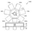
도 1을 참조하면, 기판처리설비는, 공정설비(1000), 및 설비 전방 단부 모듈(Equipment Front End Module:EFEM)(50,60,70)을 포함한다. 설비 전방 단부 모듈(50,60,70)은 공정설비(1000)의 전방에 장착되어, 복수의 기판이 수용된 용기(미도시)와 공정설비(1000) 간에 기판을 이송한다. 용기는 전면 개방 일체식 포드(Front Open Unified Pod:FOUP)와 같은 밀폐용 용기가 사용될 수 있다.Referring to FIG. 1, a substrate processing facility includes a
설비 전방 단부 모듈(50,60,70)은, 복수의 로드포트(Loadports)(60)와 프레임(50)을 포함한다. 프레임(50)은 로드포트(60)와 공정설비(1000) 사이에 배치된다. 기판을 수용하는 용기는 오버헤드 트랜스퍼(overhead transfer), 오버헤드 컨베이어(overhead conveyor), 또는 자동 안내 차량(automatic guided vehicle)과 같은 이송 수단(미도시)에 의해 로드포트(60) 상에 놓여진다.The facility
프레임(50) 내에는 로드포트(60)에 놓여진 용기와 공정설비(1000) 간에 기판을 이송하는 프레임 로봇(70)이 설치된다. 또한, 프레임(50) 내에는 용기의 도어를 자동으로 개폐하는 도어 오프너(미도시)가 설치될 수 있다. 또한, 프레임(50)에는 청정 공기가 프레임(50) 내 상부에서 하부로 흐르도록 청정 공기를 프레임(50) 내로 공급하는 팬필터 유닛(Fan Filter Unit:FFU)(미도시)이 구비될 수 있다. In the
기판은 공정설비(1000) 내에서 소정의 공정이 수행된다. 공정설비(1000)는 이송 장치(200), 로드록 장치(300), 세정 장치(500a,500b), 버퍼 장치(400), 및 에피택셜 장치(100a,100b,100c)를 포함한다. 이때, 본 발명의 실시 예에 따른 기판처리장치는 에피택셜 장치(100a,100b,100c)일 수 있다.The substrate is subjected to a predetermined process in the
이송 장치(200)는 평면형상이 다각형으로 형성되고, 로드록 장치(300), 세정 장치(500a,500b), 버퍼 장치(400), 및 에피택셜 장치(100a,100b,100c)는 이송 장치(200)의 측면에 설치된다.The
로드록 장치(300)는 이송 장치(200)의 측부들 중 설비 전방 단부 모듈(50,60,70)과 인접한 측부에 위치한다. 기판은 로드록 장치(300) 내에 일시적으로 머무른 후 이송 장치(200)에 의해 세정 장치(500a,500b), 버퍼 장치(400), 및 에피택셜 장치(100a,100b,100c)에 로딩되어 공정이 이루어진다. 공정이 완료된 후 기판은 이송 장치(200)에 의해 언로딩되어 로드록 장치(300) 내에 일시적으로 머무른다.The
이송 장치(200), 세정 장치(500a,500b), 버퍼 장치(400), 및 에피택셜 장치(100a,100b,100c)는 진공으로 유지되며, 로드록 장치(300)는 진공 및 대기압으로 전환된다. 로드록 장치(300)는 외부 오염물질이 이송 장치(200), 세정 장치(500a,500b), 버퍼 장치(400), 및 에피택셜 장치(100a,100b,100c)로 유입되는 것을 방지한다. 또한, 기판이 이송되는 동안, 기판이 대기에 노출되지 않으므로, 기판 상에 산화막이 성장하는 것을 방지할 수 있다.The
로드록 장치(300)와 이송 장치(200) 사이, 그리고 로드록 장치(300)와 설비 전방 단부 모듈(50,60,70) 사이에는 게이트 밸브(미도시)가 설치된다. 설비 전방 단부 모듈(50,60,70)과 로드록 장치(300) 간에 기판(S)이 이동하는 경우, 로드록 장치(300)와 이송 장치(200) 사이에 제공된 게이트 밸브가 닫히고, 로드록 장치(300)와 이송 장치(200) 간에 기판이 이동하는 경우, 로드록 장치(300)와 설비 전방 단부 모듈(50,60,70) 사이에 제공되는 게이트 밸브가 닫힌다.A gate valve (not shown) is installed between the
이송 장치(200)는 기판 핸들러(210)를 구비한다. 기판 핸들러(210)는 로드록 장치(300), 세정 장치(500a,500b), 버퍼 장치(400), 및 에피택셜 장치(100a,100b,100c) 사이에서 기판을 이송한다. 이송 장치(200)는 기판이 이동할 때 진공을 유지하도록 밀봉된다. 이에, 기판이 오염물에 노출되는 것을 방지할 수 있다.The
세정 장치(500a,500b)는 에피택셜 장치(100a,100b,100c) 내에서 기판에 대한 에피택셜 공정이 이루어지기 이전에 기판을 세정하는 역할을 한다. 에피택셜 공정이 성공적으로 이루어지기 위해서는 결정성 기판 상에 존재하는 산화물의 양이 최소화되어야 한다. 기판의 표면 산소 함유량이 너무 높은 경우, 산소 원자가 시드 기판 상의 증착재료의 결정학적 배치를 방해하기 때문에, 에피택셜 공정은 유해한 영향을 받는다. 따라서, 기판(S) 상에 형성된 자연 산화막(또는 표면 산화물)을 제거하는 세정 공정이 세정 장치(500a,500b) 내에서 이루어질 수 있다.The
에피택셜 장치(100a,100b,100c) 또는 본 발명의 실시 예에 따른 기판처리장치는 기판 상에 에피택셜 층을 형성하는 역할을 한다. 이때, 에피택셜 장치(100a,100b,100c)는 선택적 에피택셜 장치일 수 있다. 본 실시 예에서는 3개의 에피택셜 장치(100a,100b,100c)가 제공된다. 에피택셜 공정은 세정 공정에 비해 많은 시간이 소요되므로, 복수의 에피택셜 장치를 통해 제조수율을 향상시킬 수 있다. 그러나, 구비되는 에피택셜 장치(100a,100b,100c)의 개수는 이에 한정되지 않고 다양할 수 있다.
The
하기에서는 본 발명의 실시 예에 따른 기판처리장치(또는 에피택셜 장치)(100)에 대해 상세하게 설명하기로 한다.Hereinafter, a substrate processing apparatus (or epitaxial apparatus) 100 according to an embodiment of the present invention will be described in detail.
도 2 내지 도 5를 참조하면, 본 발명의 실시 예에 따른 기판처리장치(100)는, 튜브(130), 기판 지지부(171), 제1 가스공급부(140), 제2 가스공급부(150), 및 배기부(160)를 포함한다. 또한, 기판처리장치(100)는, 내부공간을 가지는 챔버(110), 상기 챔버(110) 내부에 배치되고 내부에 상기 튜브(130)가 수용되는 공간을 형성하는 외부튜브(120), 상기 외부튜브(120) 주변에 배치되는 히터(190), 상기 기판 지지부(171)를 지지해주는 샤프트(172), 상기 기판 지지부(171)를 상하로 이동시키는 상하구동부(173), 상기 기판 지지부(171)를 회전시키는 회전구동부(174), 및 지지판(180)을 포함할 수 있다.2 to 5, a
챔버(110)는 사각통 또는 원통 형상으로 형성되고 내부공간을 가진다. 또한, 챔버(110)는 상부챔버(110a)와 하부챔버(110b)를 포함하며, 상부챔버(110a)와 하부챔버(110b)는 서로 연통된다. 하부챔버(110b)의 일측에는 이송챔버(110)와 연통되는 삽입구가 구비된다. 이에, 기판(S)이 이송챔버(110)에서 삽입구를 통해 챔버(110)로 로딩될 수 있다. 챔버(110)의 삽입구와 대응되는 이송챔버(110)의 일측에는 유입구(220)가 형성되고, 유입구(220)와 삽입구 사이에는 게이트 밸브(230)가 구비된다. 이에, 이송챔버(110)의 내부공간과 챔버(110)의 내부공간은 게이트 벨브(230)에 의해 격리될 수 있다. 또한, 유입구(220)와 삽입구는 게이트 밸브(230)에 의해 개폐된다. 이때, 삽입구는 하부챔버(110b)에 구비될 수 있다.The
외부튜브(120)는 상부가 개방된 하부챔버(110b)의 상측 또는 상부챔버(110a)에 배치된다. 외부튜브(120)는 에피택셜 공정 또는 선택적 에피택셜 공정이 수행되는 내부공간을 가지고, 하부가 개방된다. 또한, 외부튜브(120)의 내부에는 튜브(130)가 수용될 수 있다.The
히터(190)는 챔버(110) 내부에 구비되고, 외부튜브(120) 또는 튜브(130)의 측면둘레 및 상부를 감싸도록 배치된다. 히터(190)는 외부튜브(120) 또는 튜브(130)에 열에너지를 제공하여 외부튜브(120) 또는 튜브(130)의 내부공간을 가열하는 역할을 한다. 이에, 외부튜브(120) 또는 튜브(130)의 내부공간 온도를 에피택셜 공정이 가능한 온도로 조절할 수 있다.The
튜브(130)는 하부챔버(110b)의 상측 또는 상부챔버(110a)에 배치된다. 상세하게는, 튜브(130)가 외부튜브(120)의 개방된 부분을 통해 외부튜브(120)의 내부공간에 삽입되어 외부튜브(120)의 내부공간에 배치된다. 또한, 튜브(130)는 내부에 기판 지지부(171)가 수용되는 공간을 형성하고, 하부가 개방된다. 이에, 기판 지지부(171)가 상부챔버(110a)와 하부챔버(110b) 내에서 상하로 이동하는 경우, 튜브(130)의 개구부를 통해 튜브(130) 내로 인입되거나 인출될 수 있다.The
튜브(130)는 원통 형태로 형성되고 하부가 개방될 수 있다. 또한, 튜브(130)의 둘레 일측에는, 후술될 제1 가스공급부(140)의 분사유닛(141) 및 제2 가스공급부(150)의 분사기(151)의 분사홀과 대응되는 관통홀이 형성된다. 상세하게는, 분사유닛(141)에 대응되는 관통홀은 분사유닛(141)의 연장방향을 따라 일자형태로 튜브(130)에 형성될 수 있다. 분사기(151)에 대응되는 관통홀은 분사기(151)의 일단이 삽입가능하도록 분사기(151) 일단의 단면형상을 따라 형성될 수 있다. 또한, 튜브(130)의 둘레 타측에는 배기부(160)와 연통되는 관통홀이 형성된다. 그러나, 관통홀의 형상은 이에 한정되지 않고 다양할 수 있다.The
또한, 튜브(130)의 하부는 외부튜브(120) 또는 챔버(110)의 내벽과 연결되어 지지될 수 있도록, 튜브(130)의 둘레 외측으로 돌출되어 외부튜브(120) 또는 챔버(110)에 연결되는 돌출부가 구비될 수 있다. 또한, 분사유닛(141) 및 분사기(151)를 안정적으로 지지하도록 튜브(130) 둘레 구비되어 분사유닛(141) 및 분사기(151)를 지지해주는 원판 형상의 지지유닛(135)이 구비될 수 있다. 그러나, 튜브(130)의 구조와 형상은 이에 한정되지 않고 다양할 수 있다The lower part of the
기판 지지부(171)는 복수의 기판(S)을 상하방향으로 적재한다. 예를 들어, 기판 지지부(171)는 기판 지지부(171)는 15매의 기판들을 다단으로 적재할 수 있다. 기판 지지부(171)는 복수의 기판(S)이 각각 처리되는 처리공간을 개별적으로 형성한다. 즉, 기판 지지부(171)는 상하방향으로 복수의 층을 가지고, 각 층에 하나의 기판(S)이 적재된다. 이에, 기판 지지부(171)의 각 층에 기판(S)의 처리공간이 개별적으로 형성되어 처리공간 사이의 간섭을 방지할 수 있다.The
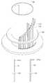
예를 들어, 도 3을 참조하면, 기판 지지부(171)는 기판 보트(Wafer Boat)(171a,171b), 히트 아이솔레이션 유닛(Heat Isolation Unit)(미도시), 및 로테이션 키트(Rotation Kit)(미도시)를 포함할 수 있다. 기판 보트(171a,171b)에는 기판(S)이 안착되도록 중심부를 향하여 돌출되는 돌기(171b)가 형성된다. 돌기(171b)는 상하방향으로 복수개가 배치되고 돌기(171b) 상에 기판(S)이 적재된다.For example, referring to FIG. 3, the
또한, 기판 보트(171a,171b)에는 처리공간 사이사이를 구분하는 복수의 아이솔레이션 플레이트(Isolation Plate)(171a)가 구비된다. 예를 들어, 아이솔레이션 플레이트(171a)는 원판 형태로 형성되고, 처리공간을 구분하도록, 복수개가 구비되어 상기 기판(S)이 적재되는 방향을 따라 상기 기판(S) 사이사이에 각각 배치된다. 즉, 기판(S)을 적재한 돌기(171b)들 사이사이에 칸막이와 같이 아이솔레이션 플레이트(171a)가 구비된다. 이에, 복수의 처리공간이 서로 고립되고 각각 독립적으로 형성된다.In addition, the
히트 아이솔레이션 유닛은 기판 보트(171a,171b)의 하부에 연결되고 튜브(130) 내부의 열손실을 방지한다. 로테이션 키트는 상부가 히트 아이솔레이션 유닛의 하부에 연결되고, 하부에 샤프트(172)가 연결된다.The heat isolation unit is connected to the bottom of the
샤프트(172)는 상하방향으로 연장형성되고, 상단이 기판 지지부(171)의 하부와 연결된다. 샤프트(172)는 기판 지지부(171)를 지지해주는 역할을 한다. 샤프트(172)의 하부는 하부챔버(110b)를 관통하여 하부챔버(110b) 외측의 상하구동부(173) 및 회전구동부(174)와 연결된다.The
상하구동부(173)는 샤프트(172)와 연결되어 샤프트(172)를 상하로 이동시킨다. 이에, 샤프트(172)의 상단에 연결된 기판 지지부(171)도 샤프트(172)의 이동을 따라 상하로 이동한다. 예를 들어, 상하구동부(173)의 작동에 의해 기판 지지부(171)가 하측으로 이동하여 하부챔버(110b)의 내부(또는 적재위치)에 위치할 수 있다. 이에, 이송챔버(110)에서 하부챔버(110b)로 로딩된 기판(S)이 하부챔버(110b) 내부에 위치한 기판 지지부(171)에 적재될 수 있다.The upper and
복수의 기판(S)이 기판 지지부(171)에 모두 적재되면 기판 지지부(171)가 상하구동부(173)에 의해 상측으로 이동하여, 외부튜브(120) 또는 튜브(130)의 내부(또는 공정위치)로 이동한다. 이에, 외부튜브(120) 또는 튜브(130) 내에서 기판(S)에 대한 에피택셜 공정이 진행될 수 있다.When the plurality of substrates S are all loaded on the
회전구동부(174)는 기판 지지부(171)를 회전시키도록 기판 지지부(171)와 연결된 샤프트(172)와 연결된다. 회전구동부(174)는 샤프트(172)의 상하방향 중심축을 기준으로 샤프트(172)를 회전시킨다. 이에, 샤프트(172)와 연결된 기판 지지부(171)도 상하방향 중심축을 기준으로 회전할 수 있다. 기판(S)의 처리공정이 진행될 때, 튜브(130)의 일측으로 공급된 1 종 이상의 가스가 기판 지지부(171)에 적재된 기판(S)을 통과하여 튜브(130)의 타측으로 배출된다. 이때, 회전구동부(174)의 작동에 의해 기판 지지부(171)가 회전하면 기판 지지부(171)를 통과하려는 가스가 믹싱되고 기판(S) 상의 면적에 균일하게 분포될 수 있다. 따라서, 기판(S) 상에 증착되는 막의 품질이 향상될 수 있다.The
지지판(180)은 샤프트(172)에 설치되고, 기판 지지부(171)와 함께 상승하여 외부튜브(120) 또는 튜브(130) 내부의 공정공간을 외부로부터 밀폐시키는 역할을 한다. 지지판(180)은 기판 지지부(171)의 하측에 이격되어 배치된다. 또한, 지지판(180)과 외부튜브(120) 사이 또는, 지지판(180)과 튜브(130) 사이에는 O링 형태의 실링부재(181)가 구비되어 공정공간을 밀폐시킨다. 지지판(180)과 샤프트(172) 사이에는 베어링부재(182)가 구비되며, 샤프트(172)는 베어링부재(182)에 의해 지지된 상태에서 회전할 수 있다.The
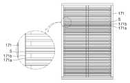
도 4 내지 도 6를 참조하면, 제1 가스공급부(140)는, 상기 기판(S)이 적재되는 방향을 따라 연장형성되는 분사유닛(141), 및 상기 분사유닛(141)에 가스를 공급하도록 상기 분사유닛(141)과 연결되는 가스공급유닛(142)을 포함한다. 이때, 제1 가스공급부(140)는 상기 복수의 기판(S)에 실리콘 원료가스 및 식각가스 공급이 가능할 수 있다. 즉, 제1 가스공급부(140)는 기판(S) 처리공정의 주요원료 가스를 처리공간 내로 공급하는 역할을 한다.4 to 6, the first gas supply unit 140 includes an
분사유닛(141)은 파이프 형태로 형성되고 기판(S)이 적재되는 방향, 예를 들어 상하방향으로 연장형성된다. 분사유닛(141)은 튜브(130)와 외부튜브(120) 사이에 배치된다. 분사유닛(141)은 상부가 폐쇄되고 하부가 가스공급유닛(142)과 연결된다. 또한, 분사유닛(141)에는 상기 기판(S)이 적재되는 방향을 따라 상기 기판(S)의 처리공간에 대응하여 배치되는 복수의 분사홀(141a)이 구비된다. 즉, 기판 지지부(171)가 형성하는 각 층과 대응되는 부분에 분사홀(141a)이 구비된다. 이에, 가스공급유닛(142)을 통해 분사유닛(141)의 내부로 공급된 제1 가스가 분사홀(141a)을 통해 기판(S)의 각 처리공간으로 공급된다.The
복수의 분사홀(141a)은, 상기 분사유닛(141)의 상기 가스공급유닛(142)이 연결되는 부분으로부터 원거리에 배치될수록 직경이 크게 형성된다. 예를 들어, 가스공급유닛(142)이 분사유닛(141)의 하단과 연결되어 제1 가스가 분사유닛(141)의 하부에서 상부로 공급되는 경우, 상측에 위치한 분사홀의 직경이 하측에 위치한 분사홀의 직경보다 크게 형성될 수 있다.The plurality of
즉, 가스공급유닛(142)과 근접한 분사홀의 경우 제1 가스가 근접한 위치에서 공급되기 때문에, 다량의 제1 가스가 유입되기 용이하다. 반면, 제1 가스공급부(140)에서 원거리에 배치되는 분사홀의 경우 제1 가스가 원거리에서 공급되기 때문에, 근접한 위치의 분사홀보다 더 먼거리를 이동하여 제1 가스를 공급받는다. 따라서, 제1 가스공급부(140)를 통해 분사유닛(141)에 제1 가스를 공급하는 경우, 제1 가스공급부(140)와 근접한 하측의 분사홀과 제1 가스공급부(140)에서 원거리에 배치되는 분사홀에서 분사되는 제1 가스의 양이 상이해질 수 있다.That is, in the case of the injection hole adjacent to the
이에, 제1 가스공급부(140)와 근접한 위치의 분사홀은 직경을 작게 하여 제1 가스가 분사될 수 있는 양을 감소시키고, 제1 가스공급부(140)와 원거리에 위치한 분사홀은 직경을 크게 하여 제1 가스가 분사될 수 있는 양을 증가시킬 수 있다. 즉, 제1 가스공급부(140)와 근접한 위치의 분사홀과 제1 가스공급부(140)에서 원거리에 배치되는 분사홀이 균일한 양의 제1 가스를 공급할 수 있도록, 분사홀(141a)들의 직경을 조절할 수 있다. 따라서, 각 층의 기판(S)들로 균일한 양의 제1 가스가 공급되어 공정의 효율이 향상될 수 있다.Accordingly, the diameter of the injection hole at a position close to the first gas supply part 140 is reduced to reduce the amount by which the first gas can be injected, and the injection hole located at a distance from the first gas supply part 140 has a large diameter So that the amount by which the first gas can be injected can be increased. That is, the diameter of the
가스공급유닛(142)은, 제1 가스가 이동하는 경로를 형성하는 제1 가스배관(142a), 1 종 이상의 가스를 각각 저장하는 하나 이상의 가스공급원, 및 각 가스공급원 별로 구비되는 하나 이상의 제어밸브를 포함한다.The
이때, 제1 가스는 실리콘 원료가스와 식각가스(Etching Gas)를 포함하고, 캐리어 가스(Carrier Gas)를 포함할 수 있다. 또한, 실리콘 원료가스로 SiH4, DCS 등을 사용할 있고, 식각가스로 HCl를 사용할 수 있고, 캐리어 가스로 H2를 사용할 수 있다. 캐리어 가스는 실리콘 원료가스 또는 식각가스의 농도를 희석시킬 수 있다. 이에, 캐리어 가스의 공급량을 제어하면 실리콘 원료가스 또는 식각가스의 농도를 제어할 수 있다. 또한, 실리콘 원료가스, 식각가스, 및 캐리어 가스는 분자량이 서로 달라 용이하게 믹싱될 수 있다. 그러나, 제1 가스의 원료는 이에 한정되지 않고 도판트 가스 등을 다양한 원료를 포함할 수 있다.At this time, the first gas includes a silicon source gas and an etching gas, and may include a carrier gas. SiH4, DCS, or the like may be used as the silicon source gas, HCl may be used as the etching gas, and H2 may be used as the carrier gas. The carrier gas may dilute the concentration of the silicon source gas or the etching gas. Therefore, the concentration of the silicon source gas or the etching gas can be controlled by controlling the supply amount of the carrier gas. Further, the silicon raw material gas, the etching gas, and the carrier gas can be easily mixed with different molecular weights. However, the raw material of the first gas is not limited thereto, but may include various raw materials such as dopant gas and the like.
제1 가스배관(142a)은 파이프 형상으로 형성되어 일단이 상기 분사유닛(141)에 연결되고, 타단이 가스공급원에 연결된다.The
가스공급원은 제1 가스가 포함하는 가스의 종류만큼 구비된다. 예를 들어, 실리콘 원료가스가 저장되는 실리콘 원료 가스공급원(142c), 식각가스가 저장되는 식각가스공급원(142e), 캐리어 가스가 저장되는 캐리어 가스공급원(142g)을 포함할 수 있다. 이에, 제1 가스배관(142a)의 타단은 경로가 분할되어 각 가스공급원에 연결된다. 즉, 실리콘 원료가스의 이동경로, 식각가스의 이동경로, 및 캐리어 가스의 이동경로가 하나로 합쳐져 분사유닛(141)과 연결된다.The gas supply source is provided by the kind of gas contained in the first gas. For example, the silicon
제어밸브(142b,142d,142f)는 각 가스공급원에 구비되어 제1 가스배관(142a)으로 공급되는 가스의 유량을 제어한다. 예를 들어, 제어밸브(142b,142d,142f)는, 실리콘 원료 가스공급원(142c)에 구비되어 실리콘 원료가스의 유량을 제어하는 실리콘 원료가스 제어밸브(142b), 식각 가스공급원(142e)에 구비되어 식각가스의 유량을 제어하는 식각가스 제어밸브(142d), 및 캐리어 가스 가스공급원(142g)에 구비되어 캐리어 가스의 유량을 제어하는 캐리어 가스 제어밸브(142f)를 포함할 수 있다. 이에, 제어밸브(142b,142d,142f)를 제어하면 분사유닛(141)을 통해 기판(S)으로 분사되는 제1 가스의 전체 유량을 제어할 수 있다. 또한, 기판(S)으로 공급되는 가스를 종류를 선택적으로 사용할 수 있다. 그러나, 사용되는 가스의 종류나 제1 가스공급부(140)의 구조는 이에 한정되지 않고 다양할 수 있다.The
제2 가스공급부(150)는, 상기 처리공간 각각에 대응되도록 높이가 서로 다르게 형성되는 복수의 분사기(151), 및 상기 분사기(151)의 일단에 각각 연결되는 복수의 가스공급라인(152)을 포함한다. 이때, 제2 가스공급부(150)는 상기 복수의 기판(S) 각각에 선택적으로 도판트 가스 또는 식각가스 공급이 가능할 수 있다. 즉, 제2 가스공급부(150)는 기판(S) 처리공정에 보조적인 가스를 처리공간 내로 공급하는 역할을 한다.The second gas supply unit 150 includes a plurality of
분사기(151)는 파이프 형태로 형성되고 기판 지지부(171)가 가지는 처리공간의 개수만큼 또는, 처리공간의 개수보다 하나 적게 구비된다. 예를 들어, 기판 지지부(171)가 15매의 기판(S)을 지지하여 15개의 기판(S) 처리공간이 형성되는 경우, 14개의 분사기(151)가 구비될 수 있다. 즉, 분사기(151)는 분사유닛(141)과 겹치는 한 부분을 제외하고, 모든 처리공간과 연결될 수 있다.The
분사기(151)의 타단에는 가스를 분사하는 분사홀(151a)이 형성되고, 분사기(151)의 타단은 처리공간을 향하여 연장형성된다. 또한, 분사기(151)는, 상기 튜브(130)와 상기 외부튜브(120) 사이에 배치된다. 예를 들어, 분사기(151)는 'ㄱ'자 형태로 형성될 수 있다. 이에, 기판(S)의 처리공간으로 돌출된 타단이 튜브(130)의 관통홀을 통해 처리공간과 접할 수 있다. 따라서, 가스공급라인(152)을 통해 분사기(151)의 일단 예를 들어, 하단으로 공급된 제2 가스가 분사기(151) 내부로 공급되어 분사홀(151a)을 통해 각 처리공간에 배치된 기판(S)으로 분사된다.A
또한, 복수의 분사기(151)는 각 처리공간 즉, 기판 지지부(171)가 형성하는 각 층으로 가스를 별도로 공급하기 위해 높이가 서로 다르게 형성된다. 즉, 하측의 처리공간과 접하는 분사기(151)는 높이가 낮고, 상측의 처리공간과 접하는 분사기(151)의 높이는 높게 형성된다. 예를 들어, 분사기(151)의 분사홀(151a)은 상기 튜브(130)의 둘레를 따라 나선형으로 배치되어, 높이가 제일 낮은 분사기(151)부터 높이가 제일 높은 분사기(151)로 순차적인 순서로 분사기(151)가 배치될 수 있다. 이에, 높이가 다른 복수의 분사기(151)가 불규칙적으로 배치될 때보다 공간의 효율이 향상될 수 있다.The plurality of
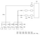
가스공급라인(152)은, 가스가 이동하는 경로를 형성하고 분사기에 각각 연결되는 제2 가스배관(152a), 상기 제2 가스배관(152a) 내 가스의 유량을 측정하도록 상기 제2 가스배관(152a)에 설치되는 유량센서(152b), 및 상기 제2 가스배관(152a) 내 가스의 유량을 제어하도록 상기 제2 가스배관(152a)에 설치되는 밸브(152a)를 포함한다.The gas supply line 152 includes a
이때, 제2 가스는 도판트 가스(Dopant Gas), 식각가스, 캐리어 가스 중 적어도 어느 하나를 포함할 수 있다. 식각가스로 HCl를 사용할 수 있고, 캐리어 가스로 H2를 사용할 수 있다. 도판트 가스는 실리콘 원료가스와 혼합되어 기판(S) 상에 박막을 증착시킬 수 있다. 이에, 기판(S)이 처리되는 처리공간 내 도판트 가스의 농도를 제어하면 실리콘 박막의 도핑 농도를 개별적으로 제어할 수 있다. 캐리어 가스는 실리콘 원료가스 또는 식각가스의 농도를 희석시킬 수 있다. 이에, 캐리어 가스의 공급량을 제어하면 실리콘 원료가스 또는 식각가스의 농도를 제어할 수 있다. 그러나, 제2 가스의 원료는 이에 한정되지 않고 실리콘 원료가스 등 다양할 수 있다.At this time, the second gas may include at least one of a dopant gas, an etching gas, and a carrier gas. HCl can be used as the etching gas, and H2 can be used as the carrier gas. The dopant gas may be mixed with the silicon source gas to deposit a thin film on the substrate S. Thus, by controlling the concentration of the dopant gas in the processing space in which the substrate S is processed, the doping concentration of the silicon thin film can be individually controlled. The carrier gas may dilute the concentration of the silicon source gas or the etching gas. Therefore, the concentration of the silicon source gas or the etching gas can be controlled by controlling the supply amount of the carrier gas. However, the raw material of the second gas is not limited thereto, and may be various, such as a silicon raw material gas.
따라서, 제2 가스의 가스 종류를 선택적으로 사용함으로, 각 처리공간 별 공정을 선택할 수 있다. 즉, 제2 가스로 식각가스만 선택하는 경우, 처리공간 내 식각가스의 혼합률이 증가하여 기판(S)에 대한 선택적 에피택셜 성장이 가능하도록 식각공정을 수행할 수 있다. 또한, 제2 가스로 도판트 가스만 선택하는 경우, 처리공간 내 도판트 가스의 혼합률이 증가하고 제1 가스의 실리콘 원료가스와 도판트 가스가 믹싱되어 기판(S) 상에 박막을 형성할 수도 있다. 또한, 제2 가스의 공급을 중단하면 제1 가스에 의해 처리공간 내 기판(S) 상에 실리콘 박막이 형성될 수도 있다.Therefore, by selectively using the gas type of the second gas, it is possible to select a process for each processing space. That is, when only the etching gas is selected as the second gas, the etching rate can be increased to increase the mixing ratio of the etching gas in the processing space, thereby performing the etching process so as to enable selective epitaxial growth on the substrate S. In addition, when only the dopant gas is selected as the second gas, the mixing ratio of the dopant gas in the processing space is increased and the silicon source gas of the first gas and the dopant gas are mixed to form a thin film on the substrate S It is possible. Further, when the supply of the second gas is stopped, a silicon thin film may be formed on the substrate S in the processing space by the first gas.
한편, 제2 가스배관(152a)이 실리콘 원료가스 공급원과 연결되는 경우, 기판(S) 상 박막의 두께를 더욱 효과적으로 제어할 수 있다. 즉, 기판(S) 상 박막의 두께가 얇은 경우, 제2 가스로 실리콘 원료가스를 공급하고, 기판(S) 상의 박막의 두께가 두꺼운 경우, 제2 가스로 식각가스를 공급하여, 기판(S) 상 박막의 두께를 조절할 수 있다. 이에, 기판(S)의 각 처리공간 별로 공급되는 제2 가스를 선택하여 처리공간 별로 기판(S)의 두께를 제어할 수 있고, 기판(S) 상 박막의 품질이 향상된다.On the other hand, when the
제2 가스배관(152a)은 파이프 형상으로 형성되어 일단이 상기 분사기(151)에 연결되고, 타단이 공급원(152e,152g,152i)에 연결된다.The
공급원(152e,152g,152i)는 제2 가스가 포함하는 가스의 종류만큼 구비된다. 예를 들어, 도판트 가스가 저장되는 도판트 가스 공급원(152e), 식각가스가 저장되는 식각가스 공급원(152g), 캐리어 가스가 저장되는 캐리어 가스 공급원(152i)을 포함할 수 있다. 제2 가스배관(152a)의 일단은 경로가 분할되어 복수의 분사기(151)에 각각 연결되고 하나로 합쳐졌다가 공급원(152e,152g,152i)의 개수만큼 분할되어 타단이 각 공급원(152e,152g,152i)과 연결된다.The
유량밸브(152d,152f,152h)는 각 공급원에 구비되어 제2 가스배관(152a)으로 공급되는 가스의 유량을 제어한다. 예를 들어, 유량밸브(152d,152f,152h)는, 도판트 가스 공급원(152e)에 구비되어 도판트 가스의 유량을 제어하는 도판트 가스 유량밸브(152d), 식각가스 공급원(152g)에 구비되어 식각가스의 유량을 제어하는 식각가스 유량밸브(152f), 및 캐리어 가스 공급원(152i)에 구비되어 캐리어 가스의 유량을 제어하는 캐리어 가스 유량밸브(152h)를 포함할 수 있다. 이에, 유량밸브(152d,152f,152h)를 제어하면, 분사기(151)를 통해 기판(S)으로 분사되는 제2 가스의 전체 유량을 제어하고, 분사되는 가스의 종류를 선택할 수 있다.The flow valves 152d, 152f, and 152h are provided in the respective sources to control the flow rate of the gas supplied to the
유량센서(152b)는 제2 가스배관(152a)의 분할된 각각의 일단에 구비된다. 즉, 각각의 처리공간으로 공급되는 제2 가스의 양을 개별적으로 측정하기 위해 처리공간의 개수만큼 구비되어 각 처리공간과 연결된 제2 가스배관(152a)의 복수의 일단에 개별적으로 구비된다. 유량센서(152b)는, 분사유닛(141)과 제2 가스배관(152a)의 일단들이 하나로 합쳐지는 부분 사이에 구비된다. 이에, 유량센서(152b)를 이용하여 각 처리공간으로 공급되는 제2 가스의 유량을 개별적으로 실시간 모니터링할 수 있다.The
밸브(152c)는 제2 가스배관(152a)의 분할된 각각의 일단에 구비된다. 즉, 각각의 처리공간으로 공급되는 제2 가스의 양을 개별적으로 제어하기 위해 처리공간의 개수만큼 구비되어 각 처리공간과 연결된 제2 가스배관(152a)의 복수의 일단에 개별적으로 구비된다. 밸브(152c)는, 분사유닛(141)과 제2 가스배관(152a)의 일단들이 하나로 합쳐지는 부분 사이에 구비된다. 또한, 밸브(152c)는 유량센서(152b)의 전단 또는 후단에 배치될 수 있다. 따라서, 밸브(152c)의 작동을 제어하면 각 처리공간으로 공급되는 제2 가스의 유량을 개별적으로 제어할 수 있다.The
이에 대해 살펴보면, 기판 지지부(171)가 형성하는 기판(S)의 처리공간 별로 기판(S) 상의 박막 두께에 차이가 발생할 수 있다. 기판(S) 상의 박막의 두께가 너무 두꺼운 경우, 처리공간으로 공급되는 도판트 가스의 양을 감소시키거나 공급되는 식각가스의 양을 증가시켜야 한다. 반대로, 기판(S) 상의 박막 두께가 너무 얇은 경우, 공급되는 도판트 가스의 양을 증가시키거나 공급되는 식각가스의 양을 감소시켜야 한다. 따라서, 각 처리공간 내의 기판(S) 상의 박막 두께가 다른 경우, 특정 기판을 기준으로 제2 가스가 공급되는 가스의 양을 제어하면 일부 기판의 박막 두께는 너무 두꺼워지고, 다른 일부 기판의 박막은 너무 얇아지는 문제가 발생한다.The thickness of the thin film on the substrate S may vary depending on the processing space of the substrate S formed by the
이에, 처리공간 별 기판(S) 상의 박막 두께를 확인하여 처리공간에 따라 공급되는 가스의 농도를 제어할 수 있다. 즉, 기판(S) 상 박막 두께에 따라 유량센서(152b)를 통해 각 처리공간으로 공급되는 가스의 유량을 측정하면서 밸브(152c)를 통해 각 처리공간으로 공급되는 가스의 유량을 제어할 수 있다. 따라서, 특정 기판(S)을 기준으로 공급되는 가스의 농도를 결정하지 않고, 처리공간 별로 독립적으로 가스의 농도를 제어할 수 있다.Accordingly, it is possible to check the thickness of the thin film on the substrate S by the processing space to control the concentration of the gas supplied according to the processing space. That is, the flow rate of the gas supplied to each processing space can be controlled through the
예를 들어, 최상측에 위치한 기판(S)의 박막 두께가 너무 두꺼운 경우, 최상측의 처리공간으로 식각가스의 공급량을 증가시켜 박막 중 일부를 식각하고, 최하측의 처리공간으로는 식각가스의 공급을 차단할 수 있다.For example, when the thin film thickness of the substrate S located on the uppermost side is too thick, the supply amount of the etching gas is increased to the uppermost processing space to etch a part of the thin film, and as the lowermost processing space, The supply can be blocked.
이에 대해 상세하게 설명하면, 기판(S)에 선택적 에피택셜 성장(Selective Epitaxial Growth: SEG) 공정을 진행 경우, 히터(190)를 이용하여 기판(S)이 수용된 모든 처리공간의 온도를 선택적 에피택셜 성장에 적합한 온도로 상승시킨다. 그 다음, 제1 가스공급부(140)를 통해 모든 처리공간으로 실리콘 원료가스, 식각가스, 및 캐리어 가스 중 적어도 어느 하나를 포함하는 제1 가스를 공급한다. 제1 가스는 기판(S)을 통과하여 배기부(160)를 통해 처리공간 외부로 배출된다. 그 다음, 제2 가스공급부(150)를 이용하여 하기의 상술된 다양한 방법으로 제2 가스를 처리공간으로 각각 공급할 수 있다.In detail, when a selective epitaxial growth (SEG) process is performed on the substrate S, the temperature of all the processing spaces in which the substrate S is accommodated by using the
첫 번째로, 모든 유량밸브(152d,152f,152h)와 제2 가스배관(152a)의 모든 밸브(152c)를 개방하여 도판트 가스, 식각가스, 및 캐리어 가스 중 적어도 어느 하나를 포함하는 제2 가스를 모든 처리공간으로 공급한다. 이에, 제1 가스와 제2 가스가 믹싱되어 기판(S) 상에 실리콘과 도판트가 혼합된 박막을 형성할 수 있다.First, all of the flow valves 152d, 152f, 152h and all of the
두 번째로, 도판트 가스 유량밸브(152d)를 잠근 후, 제2 가스배관(152a)의 모든 밸브(152c)를 개방하여 식각가스만 각 처리공간으로 공급하고, 처리공간 내 불순물을 제거할 수 있다. 또한, 식각가스는 박막을 식각하여 박막의 두께를 얇게 만들 수 있다. 즉, 실리콘 원료가스, 식각가스, 캐리어 가스 중 적어도 어느 하나를 포함하는 제1 가스가 처리공간으로 공급되는 상태에서 식각가스만을 포함하는 제2 가스를 처리공간으로 공급할 수 있다. 이에, 처리공간 내부 가스 중 식각가스의 비율이 증가하여 박막이 식각된다.Secondly, after the dopant gas flow valve 152d is closed, all the
이때, 박막의 두께가 얇은 기판(S)이 수용된 처리공간으로 공급되는 식각가스의 양을 조절할 수 있다. 즉, 두께가 얇은 기판(S)이 수용된 처리공간과 연결되는 제2 가스배관(152a)의 밸브(152c)만을 닫아 처리공간 내부로 공급되는 식각가스의 유량만을 감소시키거나 식각가스의 유입을 차단할 수 있다. 따라서, 처리공간 별로 식각가스의 공급량을 제어하여, 박막의 두께가 두꺼운 기판(S)이 수용된 처리공간으로는 많은 양의 식각가스가 공급되도록 하고, 박막의 두께가 얇은 기판(S)이 수용된 처리공간으로는 적은 양의 식각가스가 공급되거나 식각가스의 공급을 중단할 수 있다.At this time, the amount of the etching gas supplied to the processing space containing the substrate S having a thin film thickness can be adjusted. That is, only the
한편, 선공정에서 패터닝된 산화물층 또는 질화물층 등을 포함하는 기판(S)에 대해 선택적 에픽택셜 공정을 수행할 수 있다. 우선, 실리콘 원료가스를 포함하는 제1 가스를 기판 상에 공급할 수 있다. 이에, 실리콘 원료가 기판(S) 상에 증착된다. 이때, 실리콘 베어(bare) 기판 부분과 패턴이 형성된 부분에서 박막이 형성되는 속도에 차이가 있다.On the other hand, a selective epitaxial process can be performed on a substrate S including a patterned oxide layer or a nitride layer in the pre-process. First, a first gas containing a silicon raw material gas can be supplied onto a substrate. Thus, a silicon raw material is deposited on the substrate (S). At this time, there is a difference in the speed at which the silicon bare substrate and the thin film are formed at the portion where the pattern is formed.
따라서, 기판(S) 상으로 제2 가스를 공급하여 기판(S)이 처리되는 처리공간 내부의 가스 성분을 조절할 수 있다. 즉, 식각가스만 또는 식각가스와 캐리어 가스만을 포함하는 제2 가스를 기판(S)의 처리공간으로 공급하면, 제1 가스와 제2 가스가 혼합되고 제2 가스에 의해 처리공간 내부의 식각가스의 비율이 증가한다. 이에, 기판(S)의 박막 형성이 느린 부분에서는 박막이 성장하기 전에 식각가스에 의해 제거된다. 반대로, 기판(S)의 박막 형성이 빠른 부분에서는 박막이 식각가스에 제거되기 전에 증착되어 박막이 성장할 수 있다. 따라서, 제2 가스의 식각가스 농도를 제어하면 선택적 에피택셜 공정을 수행할 수 있다.Thus, the second gas can be supplied onto the substrate S to control the gas component inside the processing space in which the substrate S is processed. That is, when only the etching gas or the second gas containing only the etching gas and the carrier gas is supplied to the processing space of the substrate S, the first gas and the second gas are mixed and the etching gas . Thus, at the portion where the thin film formation of the substrate S is slow, the thin film is removed by the etching gas before it is grown. On the contrary, in a portion where the thin film is formed on the substrate S, the thin film may be deposited before the thin film is removed by the etching gas, so that the thin film can grow. Therefore, the selective epitaxial process can be performed by controlling the etching gas concentration of the second gas.
또한, 제2 가스공급부(150)의 처리공간 별로 구비된 밸브(152c)에 의해 각각의 처리공간으로 공급되는 제2 가스의 양을 처리공간 별로 개별적으로 제어할 수 있다. 이에, 처리공간 별로 식각가스의 농도를 제어하면, 일부 기판에서는 박막증착이 활발히 일어나고, 다른 기판에서는 박막 증착을 둔화시켜 기판(S) 상 박막의 성장속도에 따라 기판(S)의 처리환경을 선택적으로 제어할 수 있다.In addition, the amount of the second gas supplied to each processing space can be individually controlled by the
세 번째로, 도판트 가스 유량밸브(152d)는 개방하고 식각가스 유량밸브(152f)는 잠근 후, 제2 가스배관(152a)의 모든 밸브(152c)를 개방하여 도판트 가스만 각 처리공간으로 공급할 수 있다. 처리공간으로 공급된 도판트 가스는 제1 가스와 혼합되어 기판(S) 상에 박막을 형성한다. 이때, 박막의 실리콘 박막의 도핑농도가 높은 처리공간으로 공급되는 도판트 가스의 양을 조절할 수 있다.Third, the dopant gas flow valve 152d is opened, the etching gas flow valve 152f is closed, and then all the
즉, 박막의 도핑농도가 높은 처리공간과 연결되는 제2 가스배관(152a)제2 가스배관(152a)닫아 처리공간 내부로 공급되는 도판트 가스의 유량만 감소시키거나 도판트 가스의 유입을 차단할 수 있다. 따라서, 처리공간 별로 도판트 가스의 공급량을 제어하여, 박막의 도핑농도가 높은 처리공간으로는 적은 양의 도판트 가스가 공급되거나 도판트 가스의 공급을 중단하고, 박막의 도핑농도가 낮은 처리공간으로는 많은 양의 도판트 가스가 공급되도록 할 수 있다.That is, the
네 번째로, 도판트 가스 유량밸브(152d)와 식각가스 유량밸브(152f)를 모두 잠그고, 제2 가스배관(152a)의 모든 밸브(152c)를 잠글 수 있다. 이에, 처리공간 내부로 제1 가스만 공급되기 때문에, 실리콘 원료가스에 의해 기판(S) 상에 실리콘 박막만 형성될 수 있다.Fourth, both the dopant gas flow rate valve 152d and the etching gas flow rate valve 152f can be locked and all
이러한 과정들의 다양한 조합을 통해 기판(S)에 고품질의 박막 즉, 고품질의 선택 에피택셜 막을 형성할 수 있다. 또한, 기판(S)의 처리공간 별로 독립적으로 기판(S) 처리가 수행될 수 있는 최상의 조건을 조성하여 생산되는 기판(S) 또는 기판(S) 상의 박막의 품질이 향상된다. 그러나, 도판트 가스, 식각가스 등이 공급되는 순서 및 방법은 이에 한정되지 않고 다양할 수 있다.A high-quality thin film, that is, a high-quality selective epitaxial film, can be formed on the substrate S through various combinations of these processes. Further, the quality of the thin film on the substrate S or the substrate S to be produced is improved by forming the best condition in which the substrate S treatment can be independently performed for each processing space of the substrate S. However, the order and method of supplying dopant gas, etch gas, and the like are not limited to this, and may vary.
한편, 제1 가스를 공급하는 제1 가스공급부(140)와 제2 가스를 공급하는 제2 가스공급부(150)를 별도로 구비하므로, 복수의 처리공간 각각으로 공급되는 가스의 혼합비율을 제어할 수 있다. 즉, 제1 가스공급부(140)는 기판(S) 처리공정의 메인가스(제1 가스)를 모든 처리공간으로 공급하여 기판(S) 상에 실리콘 박막을 증착시킬 수 있다. 제2 가스공급부(150)는 기판(S) 처리공정의 보조적인 가스(제2 가스)를 공급하여 메인가스와 혼합된다. 이때, 제2 가스공급부(150)는 도판트 가스 또는 식각가스 중 적어도 어느 하나를 선택해서 각각의 처리공간으로 공급한다. 이에, 처리공간 내부의 도판트 가스의 농도를 증가시키거나 식각가스의 농도를 증가시킬 수 있다. 따라서, 제2 가스공급부(150)에서 공급한 가스는 제1 가스공급부(140)에서 공급하는 가스의 성분 비율을 조절한다. 즉, 제2 가스의 공급을 통해 제1 가스 또는 처리공간 내부의 가스를 튜닝(Tunning)할 수 있다.Since the first gas supply unit 140 for supplying the first gas and the second gas supply unit 150 for supplying the second gas are provided separately, it is possible to control the mixing ratio of the gas supplied to each of the plurality of process spaces have. That is, the first gas supply unit 140 may supply the main gas (first gas) in the substrate S processing process to all the processing spaces to deposit the silicon thin film on the substrate S. The second gas supply unit 150 supplies an auxiliary gas (a second gas) in the process of the substrate S and is mixed with the main gas. At this time, the second gas supply unit 150 selects at least one of the dopant gas and the etching gas, and supplies the selected gas to the respective processing spaces. Thus, the concentration of the dopant gas in the processing space can be increased or the concentration of the etching gas can be increased. Therefore, the gas supplied from the second gas supply unit 150 regulates the component ratio of the gas supplied from the first gas supply unit 140. That is, the first gas or the gas inside the processing space can be tuned through the supply of the second gas.
예를 들어, 제2 가스로 식각가스를 공급하면 처리공간 내부의 식각가스의 공급비율이 증가하여, 선택적 에피택셜 성장이 가능하도록 식각공정을 수행할 수 있다. 반대로, 제2 가스로 도판트 가스를 공급하면 처리공간 내부의 도판트 가스의 비율이 증가하여, 처리공간 내에서 도핑 공정이 활발히 수행될 수 있다. 이에, 제2 가스공급부(150)가 공급하는 가스의 종류를 선택하면, 처리공간 내부에서 도핑공정을 수행할지 식각공정을 수행할지 또는, 선택적 에피택셜 공정을 수행할지 등을 선택할 수 있다.For example, when the etching gas is supplied to the second gas, the etching gas may be supplied to the interior of the processing space to increase the etching rate so that selective epitaxial growth is possible. On the contrary, when the dopant gas is supplied to the second gas, the proportion of the dopant gas in the processing space increases, and the doping process can be actively performed in the processing space. If the type of gas supplied by the second gas supply unit 150 is selected, it is possible to select whether to perform the doping process, the etching process, or the selective epitaxial process in the process space.
또한, 제2 가스공급부(150)는 복수의 처리실 각각으로 공급되는 제2 가스의 유량을 개별적으로 제어할 수 있다. 이에, 제2 가스공급부(150)를 통해 각각의 처리공간 내부의 가스 성분을 개별적으로 조절할 수 있다. 이에, 각각의 처리공간 내부의 환경을 개별적으로 제어하기가 용이하고 장비의 구성이 단순해질 수 있다.Further, the second gas supply unit 150 can individually control the flow rate of the second gas supplied to each of the plurality of processing chambers. Accordingly, the gas components in the respective processing spaces can be individually adjusted through the second gas supply unit 150. [ Thus, the environment inside each processing space can be controlled individually and the configuration of the equipment can be simplified.
반면, 제1 가스공급부(140)와 제2 가스공급부(150)를 별도로 구비하지 않고, 하나의 가스공급부를 통해 복수의 처리공간으로 처리가스를 공급하는 경우, 복수의 처리공간 내부의 가스 성분을 개별적으로 제어할 수 없다. 즉, 전체 처리공간 대한 가스 성분만 제어할 수 있을 뿐, 처리공간 별로 처리공간 내부의 가스 성분을 제어할 수 없다. 이에, 특정 처리공간을 기준으로 처리가스를 공급하는 경우, 다른 처리공간 내의 기판 상에는 박막이 제대로 증착되지 않거나 너무 많이 증착되는 문제가 발생할 수 있다.On the other hand, when the first gas supply unit 140 and the second gas supply unit 150 are not separately provided and the process gas is supplied to a plurality of process spaces through one gas supply unit, You can not control them individually. That is, only the gas component of the entire processing space can be controlled, and the gas component in the processing space can not be controlled by the processing space. Therefore, when the process gas is supplied based on a specific process space, there may occur a problem that the thin film is not properly deposited on the substrate in another process space or that too much is deposited.
또한, 복수의 처리공간 각각에, 실리콘 원료가스 공급원, 도판트 가스 공급원, 식각가스 공급원, 캐리어 가스 공급원을 연결하는 경우, 처리공간 내부의 가스를 튜닝하는데 어려움이 있다. 즉, 각각의 처리공간으로 공급되는 가스는 선택할 수 있지만 가스의 유량을 제어할 수 있는 구성이 구비되지 않아 튜닝하는데 한계가 있다. 반면, 본 발명의 실시 예에 따른 제2 가스공급부(150)는, 각각의 가스 공급원의 유량을 제어하는 제어밸브(152d,152f,152h)와 별도로 각각의 처리공간으로 공급되는 제2 가스의 유량을 제어하는 별도의 밸브(152c)와 유량센서(152b)가 구비되어 용이하게 처리공간으로 공급되는 가스의 종류 및 유량을 제어할 수 있다.Further, when connecting the silicon source gas source, the dopant gas source, the etching gas source, and the carrier gas source to each of the plurality of processing spaces, it is difficult to tune the gas inside the processing space. That is, although the gas to be supplied to each processing space can be selected, there is no configuration for controlling the flow rate of the gas, and there is a limitation in tuning. On the other hand, the second gas supply unit 150 according to the embodiment of the present invention includes the control valves 152d, 152f, 152h for controlling the flow rates of the respective gas supply sources, the flow rates of the second gas supplied to the respective processing spaces A
또한, 복수의 처리공간 각각에, 실리콘 원료가스 공급원, 도판트 가스 공급원, 식각가스 공급원, 캐리어 가스 공급원을 연결하는 경우, 처리공간이 늘어날수록 구비해야하는 가스들의 공급원이 증가하고, 가스배관의 연결관계가 복잡해져 장비의 부피가 증가할 수 있다. 장비가 복잡해질수록 장비의 유지보수가 어려워지는 문제가 발생한다.Further, in the case of connecting the silicon source gas source, the dopant gas source, the etching gas source, and the carrier gas source to each of the plurality of processing spaces, the supply source of the gas to be provided increases as the processing space increases, The volume of the equipment may increase. The more complicated the equipment, the more difficult it is to maintain the equipment.
배기부(160)는, 상기 튜브(130)의 내부공간과 연통되는 배기홀을 구비하고 상기 튜브(130)의 타측에 설치되는 배기관(161), 일단이 상기 배기관(161)과 연결되는 배기라인(162), 및 상기 배기라인(162)의 타단과 연결되는 배기펌프(미도시)를 포함한다. 배기관(161)의 배기홀은 튜브(130)의 둘레 일측에 배치되는 분사유닛(141)의 분사홀과 대응되는 위치에 배치된다. 또한, 배기라인(162)에는 배기가스 제어밸브(미도시)가 구비되어 배기라인(162)을 개폐할 수 있다. 이에, 배기부(160)는 튜브(130) 내부의 가스나 반응부산물을 튜브(130) 외부로 배출할 수 있다. 그러나, 기판처리장치(100)의 구조와 형상은 이에 한정되지 않고 다양할 수 있다.The
이처럼, 복수의 기판(S)이 처리되는 처리공간마다 개별적으로 가스를 공급할 수 있는 가스공급부(140,150)를 구비하여, 각 기판(S)의 상황에 따라 처리공간으로 공급되는 가스의 양을 별도로 제어할 수 있다. 따라서, 각 기판(S)이 최상의 조건에서 처리공정이 수행될 수 있기 때문에, 기판(S) 또는 기판(S) 상의 박막의 품질이 향상된다.As described above, the gas supply units 140 and 150, which are capable of supplying gas individually to the processing spaces in which the plurality of substrates S are processed, are provided so that the amount of gas supplied to the processing space is controlled separately can do. Thus, the quality of the thin film on the substrate S or the substrate S is improved since each substrate S can be processed under the best conditions.
또한, 가스공급부(140,150)가 처리공정의 상황에 따라 선택적으로 한 종류 이상의 가스를 처리공간으로 공급할 수 있기 때문에, 기판(S) 상에 형성되는 박막의 두께를 조절할 수 있기 때문에, 기판(S) 또는 기판(S) 상의 박막의 품질이 향상된다.Since the thickness of the thin film formed on the substrate S can be adjusted since the gas supplying units 140 and 150 can selectively supply one or more kinds of gas to the processing space according to the process conditions, Or the quality of the thin film on the substrate S is improved.
또한, 처리공간 별로 공급되는 가스의 양 및 가스의 종류를 제어할 수 있기 때문에, 기판(S)의 상황에 따라 처리공정의 조건을 신속하게 제어할 수 있다. 이에, 기판(S) 또는 기판(S) 상의 박막에 불량이 발생되는 것이 감소하여 기판처리공정의 효율이 향상된다.Further, since the amount of gas supplied and the kind of gas to be supplied to each processing space can be controlled, the conditions of the processing step can be quickly controlled according to the situation of the substrate S. Thus, the occurrence of defects in the thin film on the substrate S or the substrate S is reduced, and the efficiency of the substrate processing process is improved.
또한, 주원료 가스를 공급하는 제1 가스공급부(140)와 1종 이상의 가스 중 적어도 어느 하나를 선택적으로 공급할 수 있는 제2 가스공급부(150)를 포함하여, 제2 가스공급부에서 공급되는 가스를 선택하여 처리공간 내 가스의 혼합비율을 제어할 수 있다. 또한, 제2 가스공급부(150)에서 공급되는 가스를 선택하여 기판(S)에 대한 다양한 처리공정을 선택적으로 수행할 수 있다.
The first gas supply unit 140 for supplying the raw material gas and the second gas supply unit 150 for selectively supplying at least one of the at least one gas may be used to select the gas supplied from the second gas supply unit So that the mixing ratio of the gas in the processing space can be controlled. In addition, various processes for the substrate S can be selectively performed by selecting the gas supplied from the second gas supply unit 150.
이와 같이, 본 발명의 상세한 설명에서는 구체적인 실시 예에 관해 설명하였으나, 본 발명의 범주에서 벗어나지 않는 한도 내에서 여러 가지 변형이 가능하다. 그러므로, 본 발명의 범위는 설명된 실시 예에 국한되어 정해져서는 안되며, 아래에 기재될 특허청구범위뿐만 아니라 이 청구범위와 균등한 것들에 의해 정해져야 한다.Although the present invention has been described in detail with reference to the specific embodiments thereof, it will be apparent to those skilled in the art that various modifications and variations can be made without departing from the scope of the present invention. Therefore, the scope of the present invention should not be limited by the described embodiments, but should be defined by the appended claims, as well as the appended claims.
100: 기판처리장치110: 챔버
120: 외부튜브130: 튜브
140: 제1 가스공급부150: 제2 가스공급부
160: 배기부171: 기판 지지부
180: 지지판190: 히터100: substrate processing apparatus 110: chamber
120: outer tube 130: tube
140: first gas supply unit 150: second gas supply unit
160: exhaust part 171:
180: support plate 190: heater
Claims (12)
Translated fromKorean상기 튜브(130) 내부에서 복수의 기판을 다단으로 적재하고 상기 복수의 기판이 각각 처리되는 복수의 처리공간을 개별적으로 형성하는 기판 지지부(171);
모든 상기 복수의 처리공간에 기판을 처리하는 공정의 메인가스인 제1 가스를 공급하는 제1 가스공급부(140);
상기 복수의 기판 각각에 기판을 처리하는 공정의 보조가스인 제2 가스를 개별적으로 공급하도록 상기 복수의 처리공간 각각에 대응되게 배치되는 복수의 분사기(151)를 구비하고, 복수의 처리공간 각각으로 공급되는 제2 가스의 유량을 개별적으로 제어 가능한 제2 가스공급부(150); 및
상기 튜브(130) 내 가스를 배기하는 배기부(160)를 포함하며,
상기 메인가스는 실리콘 원료가스를 포함하고, 상기 보조가스는 도판트 가스 및 식각가스 중 적어도 어느 하나를 포함하는 기판처리장치.A tube 130 in which a space is formed;
A substrate support 171 for mounting a plurality of substrates in a plurality of stages in the tube 130 and separately forming a plurality of process spaces in which the plurality of substrates are respectively processed;
A first gas supply unit (140) for supplying a first gas, which is a main gas in a process of processing substrates to all of the plurality of process spaces;
And a plurality of injectors (151) arranged so as to respectively supply the second gas, which is an auxiliary gas in the process of processing the substrate to each of the plurality of substrates, to each of the plurality of processing spaces, A second gas supply unit 150 capable of individually controlling the flow rate of the supplied second gas; And
And an exhaust part (160) for exhausting gas in the tube (130)
Wherein the main gas comprises a silicon source gas and the auxiliary gas comprises at least one of a dopant gas and an etching gas.
상기 제1 가스공급부는,
상기 기판이 적재되는 방향을 따라 연장형성되는 분사유닛; 및
상기 분사유닛에 가스를 공급하도록 상기 분사유닛과 연결되는 가스공급유닛을 포함하고,
상기 분사유닛에 상기 기판이 적재되는 방향을 따라 상기 처리공간에 대응하여 배치되는 복수의 분사홀이 구비되는 기판처리장치.The method according to claim 1,
Wherein the first gas supply unit includes:
An ejection unit extending along a direction in which the substrate is loaded; And
And a gas supply unit connected to the injection unit to supply gas to the injection unit,
And a plurality of ejection holes arranged corresponding to the processing space along a direction in which the substrate is loaded on the ejection unit.
상기 복수의 분사홀은, 상기 분사유닛의 상기 가스공급유닛이 연결되는 부분으로부터 원거리에 배치될수록 직경이 커지는 기판처리장치.The method of claim 2,
Wherein the plurality of injection holes are larger in diameter as they are disposed at a distance from a portion to which the gas supply unit of the injection unit is connected.
상기 제2 가스공급부는,
상기 처리공간 각각에 대응되도록 높이가 서로 다르게 형성되는 복수의 분사기; 및
상기 분사기의 일단에 각각 연결되는 복수의 가스공급라인을 포함하는 기판처리장치.The method according to claim 1,
Wherein the second gas supply unit includes:
A plurality of injectors formed at different heights to correspond to the respective processing spaces; And
And a plurality of gas supply lines respectively connected to one end of the injector.
상기 분사기의 타단에 가스를 분사하는 분사홀이 형성되고,
상기 분사홀은 상기 튜브의 둘레를 따라 나선형으로 배치되는 기판처리장치.The method of claim 4,
An injection hole for injecting a gas is formed at the other end of the injector,
Wherein the injection holes are arranged spirally along the circumference of the tube.
상기 복수의 가스공급라인 각각은,
가스가 이동하는 경로를 형성하고 분사기에 각각 연결되는 가스배관;
상기 가스배관 내 가스의 유량을 측정하도록 상기 가스배관에 설치되는 유량센서; 및
상기 가스배관 내 가스의 유량을 제어하도록 상기 가스배관에 설치되는 밸브를 포함하고,
상기 복수의 가스공급라인은 개별적으로 가스의 유량이 측정 및 제어되는 기판처리장치.The method of claim 4,
Wherein each of the plurality of gas supply lines includes:
A gas pipe forming a path through which the gas moves and connected to the injector, respectively;
A flow rate sensor installed in the gas pipe to measure a flow rate of the gas in the gas pipe; And
And a valve installed in the gas pipe to control a flow rate of the gas in the gas pipe,
Wherein the plurality of gas supply lines are individually measured and controlled for the flow rate of the gas.
상기 튜브의 둘레에, 상기 제1 가스공급부에 구비되는 분사홀 및 상기 제2 가스공급부에 구비되는 분사홀과 대응되는 관통홀이 형성되는 기판처리장치.The method according to claim 1,
Wherein a through hole corresponding to the injection hole provided in the first gas supply unit and the injection hole provided in the second gas supply unit is formed around the tube.
상기 기판 지지부를 회전시키도록 상기 기판 지지부와 연결되는 회전구동부를 포함하는 기판처리장치.The method according to claim 1,
And a rotation driving part connected to the substrate supporting part to rotate the substrate supporting part.
내부에 상기 튜브를 수용하는 외부튜브를 포함하고,
상기 제1 가스공급부의 분사유닛 및 상기 제2 가스공급부의 분사기는, 상기 튜브와 상기 외부튜브 사이에 배치되는 기판처리장치.The method according to claim 1,
And an outer tube accommodating the tube therein,
Wherein the injection unit of the first gas supply unit and the injector of the second gas supply unit are disposed between the tube and the outer tube.
상기 기판 지지부는, 상기 복수의 처리공간이 서로 고립되도록 상기 기판이 적재되는 방향을 따라 상기 기판 사이사이에 각각 배치되는 복수의 아이솔레이션 플레이트를 포함하는 기판처리장치.The method according to claim 1,
Wherein the substrate support portion includes a plurality of isolation plates that are respectively disposed between the substrates along the direction in which the substrates are stacked so that the plurality of process spaces are isolated from each other.
Priority Applications (6)
| Application Number | Priority Date | Filing Date | Title |
|---|---|---|---|
| KR1020150052533AKR101682154B1 (en) | 2015-04-14 | 2015-04-14 | Substrate Processing Apparatus |
| TW105109790ATWI636486B (en) | 2015-04-14 | 2016-03-29 | Substrate processing apparatus |
| JP2017549489AJP6475863B2 (en) | 2015-04-14 | 2016-04-12 | Substrate processing equipment |
| US15/566,694US10741396B2 (en) | 2015-04-14 | 2016-04-12 | Substrate processing apparatus |
| CN201680021625.3ACN107438895B (en) | 2015-04-14 | 2016-04-12 | Substrate processing apparatus |
| PCT/KR2016/003861WO2016167554A1 (en) | 2015-04-14 | 2016-04-12 | Substrate processing apparatus |
Applications Claiming Priority (1)
| Application Number | Priority Date | Filing Date | Title |
|---|---|---|---|
| KR1020150052533AKR101682154B1 (en) | 2015-04-14 | 2015-04-14 | Substrate Processing Apparatus |
Publications (2)
| Publication Number | Publication Date |
|---|---|
| KR20160122523A KR20160122523A (en) | 2016-10-24 |
| KR101682154B1true KR101682154B1 (en) | 2016-12-02 |
Family
ID=57127284
Family Applications (1)
| Application Number | Title | Priority Date | Filing Date |
|---|---|---|---|
| KR1020150052533AActiveKR101682154B1 (en) | 2015-04-14 | 2015-04-14 | Substrate Processing Apparatus |
Country Status (6)
| Country | Link |
|---|---|
| US (1) | US10741396B2 (en) |
| JP (1) | JP6475863B2 (en) |
| KR (1) | KR101682154B1 (en) |
| CN (1) | CN107438895B (en) |
| TW (1) | TWI636486B (en) |
| WO (1) | WO2016167554A1 (en) |
Families Citing this family (4)
| Publication number | Priority date | Publication date | Assignee | Title |
|---|---|---|---|---|
| KR101912886B1 (en) | 2017-03-07 | 2018-10-29 | 에이피시스템 주식회사 | Apparatus for spraying gas and facility for processing substrate having the same and method for treating substrate using the same |
| US10446393B2 (en)* | 2017-05-08 | 2019-10-15 | Asm Ip Holding B.V. | Methods for forming silicon-containing epitaxial layers and related semiconductor device structures |
| US12428731B2 (en) | 2022-07-12 | 2025-09-30 | Applied Materials, Inc. | Flow guide structures and heat shield structures, and related methods, for deposition uniformity and process adjustability |
| US12428753B2 (en) | 2022-12-14 | 2025-09-30 | Applied Materials, Inc. | Lift assemblies, and related methods and components, for substrate processing chambers |
Citations (3)
| Publication number | Priority date | Publication date | Assignee | Title |
|---|---|---|---|---|
| KR101364701B1 (en)* | 2011-11-17 | 2014-02-20 | 주식회사 유진테크 | Apparatus for processing substrate with process gas having phase difference |
| KR101371435B1 (en) | 2012-01-04 | 2014-03-12 | 주식회사 유진테크 | Apparatus for processing substrate including processing unit |
| US20140357058A1 (en) | 2013-06-03 | 2014-12-04 | Hitachi Kokusai Electric Inc. | Substrate processing apparatus, method of manufacturing semiconductor device, and non-transitory computer-readable recording medium |
Family Cites Families (16)
| Publication number | Priority date | Publication date | Assignee | Title |
|---|---|---|---|---|
| JP3115015B2 (en)* | 1991-02-19 | 2000-12-04 | 東京エレクトロン株式会社 | Vertical batch processing equipment |
| JPH06326038A (en) | 1993-05-14 | 1994-11-25 | Canon Inc | Vapor growth device |
| JP3318067B2 (en) | 1993-07-27 | 2002-08-26 | 株式会社日立国際電気 | Method for producing phosphorus-doped silicon film, semiconductor manufacturing apparatus and semiconductor device manufacturing method |
| JP2003045864A (en) | 2001-08-02 | 2003-02-14 | Hitachi Kokusai Electric Inc | Substrate processing equipment |
| KR100829327B1 (en) | 2002-04-05 | 2008-05-13 | 가부시키가이샤 히다치 고쿠사이 덴키 | Substrate Processing Unit and Reaction Vessel |
| CN100456435C (en)* | 2004-11-01 | 2009-01-28 | 株式会社日立国际电气 | Substrate processing apparatus and method for manufacturing semiconductor device |
| US20070240644A1 (en)* | 2006-03-24 | 2007-10-18 | Hiroyuki Matsuura | Vertical plasma processing apparatus for semiconductor process |
| JP5730496B2 (en)* | 2009-05-01 | 2015-06-10 | 株式会社日立国際電気 | Heat treatment apparatus, semiconductor device manufacturing method, and substrate processing method |
| JP5813303B2 (en)* | 2009-11-20 | 2015-11-17 | 株式会社日立国際電気 | Semiconductor device manufacturing method, substrate processing method, and substrate processing apparatus |
| KR101223489B1 (en)* | 2010-06-30 | 2013-01-17 | 삼성디스플레이 주식회사 | Apparatus for Processing Substrate |
| JP2011142347A (en) | 2011-04-08 | 2011-07-21 | Hitachi Kokusai Electric Inc | Substrate processing apparatus |
| KR101308111B1 (en)* | 2011-11-17 | 2013-09-26 | 주식회사 유진테크 | Apparatus and method for processing substrate including exhaust ports |
| JP2014116484A (en) | 2012-12-11 | 2014-06-26 | Tokyo Electron Ltd | Substrate processing apparatus and processing container internal pressure adjustment method |
| KR101392378B1 (en) | 2013-03-27 | 2014-05-12 | 주식회사 유진테크 | Apparatus for processing substrate |
| JP6125946B2 (en)* | 2013-08-08 | 2017-05-10 | 株式会社日立国際電気 | Semiconductor device manufacturing method, substrate processing apparatus, and program |
| US9831083B2 (en)* | 2013-09-27 | 2017-11-28 | Hitachi Kokusai Electric Inc. | Method of manufacturing semiconductor device, substrate processing apparatus and non-transitory computer-readable recording medium |
- 2015
- 2015-04-14KRKR1020150052533Apatent/KR101682154B1/enactiveActive
- 2016
- 2016-03-29TWTW105109790Apatent/TWI636486B/enactive
- 2016-04-12USUS15/566,694patent/US10741396B2/enactiveActive
- 2016-04-12CNCN201680021625.3Apatent/CN107438895B/enactiveActive
- 2016-04-12JPJP2017549489Apatent/JP6475863B2/enactiveActive
- 2016-04-12WOPCT/KR2016/003861patent/WO2016167554A1/ennot_activeCeased
Patent Citations (3)
| Publication number | Priority date | Publication date | Assignee | Title |
|---|---|---|---|---|
| KR101364701B1 (en)* | 2011-11-17 | 2014-02-20 | 주식회사 유진테크 | Apparatus for processing substrate with process gas having phase difference |
| KR101371435B1 (en) | 2012-01-04 | 2014-03-12 | 주식회사 유진테크 | Apparatus for processing substrate including processing unit |
| US20140357058A1 (en) | 2013-06-03 | 2014-12-04 | Hitachi Kokusai Electric Inc. | Substrate processing apparatus, method of manufacturing semiconductor device, and non-transitory computer-readable recording medium |
Also Published As
| Publication number | Publication date |
|---|---|
| KR20160122523A (en) | 2016-10-24 |
| JP2018514084A (en) | 2018-05-31 |
| JP6475863B2 (en) | 2019-02-27 |
| CN107438895B (en) | 2021-05-04 |
| TW201701321A (en) | 2017-01-01 |
| TWI636486B (en) | 2018-09-21 |
| US20180090323A1 (en) | 2018-03-29 |
| CN107438895A (en) | 2017-12-05 |
| WO2016167554A1 (en) | 2016-10-20 |
| US10741396B2 (en) | 2020-08-11 |
Similar Documents
| Publication | Publication Date | Title |
|---|---|---|
| JP5899318B2 (en) | Semiconductor manufacturing equipment for epitaxial processes | |
| KR101271248B1 (en) | Equipment for manufacturing semiconductor | |
| JP5844900B2 (en) | Semiconductor manufacturing equipment for epitaxial processes | |
| JP5610438B2 (en) | Substrate processing apparatus and semiconductor device manufacturing method | |
| US9103029B2 (en) | Processing apparatus and film forming method | |
| US20100229795A1 (en) | Substrate processing apparatus | |
| KR101685096B1 (en) | Apparatus for processing substrate and method for processing substrate using the same | |
| KR101682154B1 (en) | Substrate Processing Apparatus | |
| JP6431620B2 (en) | Substrate processing equipment | |
| JP2011052319A (en) | Method of manufacturing semiconductor device, substrate processing apparatus, and semiconductor device | |
| US20110309562A1 (en) | Support structure and processing apparatus | |
| US20110305835A1 (en) | Systems and methods for a gas treatment of a number of substrates | |
| JP2014524657A (en) | Semiconductor manufacturing equipment for epitaxial processes | |
| US10692745B2 (en) | Substrate processing apparatus | |
| CN102277561B (en) | System and method for a gas treatment of a number of substrates | |
| JP2006286716A (en) | Manufacturing method of semiconductor device | |
| JP2012138530A (en) | Substrate manufacturing method, semiconductor device manufacturing method and substrate processing apparatus | |
| JP2012195422A (en) | Method of manufacturing substrate, method of manufacturing semiconductor device, and substrate processing device | |
| JP2007194331A (en) | Substrate processing equipment | |
| JP5385439B2 (en) | Semiconductor device manufacturing method and substrate processing apparatus | |
| WO2012077680A1 (en) | Method for producing substrate, method for producing semiconductor device, and substrate treatment device |
Legal Events
| Date | Code | Title | Description |
|---|---|---|---|
| A201 | Request for examination | ||
| PA0109 | Patent application | Patent event code:PA01091R01D Comment text:Patent Application Patent event date:20150414 | |
| PA0201 | Request for examination | ||
| E902 | Notification of reason for refusal | ||
| PE0902 | Notice of grounds for rejection | Comment text:Notification of reason for refusal Patent event date:20160510 Patent event code:PE09021S01D | |
| PG1501 | Laying open of application | ||
| E701 | Decision to grant or registration of patent right | ||
| PE0701 | Decision of registration | Patent event code:PE07011S01D Comment text:Decision to Grant Registration Patent event date:20161123 | |
| GRNT | Written decision to grant | ||
| PR0701 | Registration of establishment | Comment text:Registration of Establishment Patent event date:20161128 Patent event code:PR07011E01D | |
| PR1002 | Payment of registration fee | Payment date:20161129 End annual number:3 Start annual number:1 | |
| PG1601 | Publication of registration | ||
| FPAY | Annual fee payment | Payment date:20191030 Year of fee payment:4 | |
| PR1001 | Payment of annual fee | Payment date:20191030 Start annual number:4 End annual number:4 | |
| PR1001 | Payment of annual fee | Payment date:20201102 Start annual number:5 End annual number:5 | |
| PR1001 | Payment of annual fee | Payment date:20211026 Start annual number:6 End annual number:6 | |
| PR1001 | Payment of annual fee | Payment date:20221107 Start annual number:7 End annual number:9 |