KR101682081B1 - Methods of dry stripping boron-carbon films - Google Patents
Methods of dry stripping boron-carbon filmsDownload PDFInfo
- Publication number
- KR101682081B1 KR101682081B1KR1020137031377AKR20137031377AKR101682081B1KR 101682081 B1KR101682081 B1KR 101682081B1KR 1020137031377 AKR1020137031377 AKR 1020137031377AKR 20137031377 AKR20137031377 AKR 20137031377AKR 101682081 B1KR101682081 B1KR 101682081B1
- Authority
- KR
- South Korea
- Prior art keywords
- boron
- carbon
- substrate
- plasma
- chamber
- Prior art date
- Legal status (The legal status is an assumption and is not a legal conclusion. Google has not performed a legal analysis and makes no representation as to the accuracy of the status listed.)
- Active
Links
- PPWPWBNSKBDSPK-UHFFFAOYSA-N[B].[C]Chemical compound[B].[C]PPWPWBNSKBDSPK-UHFFFAOYSA-N0.000titleclaimsabstractdescription120
- 238000000034methodMethods0.000titleclaimsabstractdescription64
- 239000000758substrateSubstances0.000claimsabstractdescription86
- 229910052760oxygenInorganic materials0.000claimsabstractdescription75
- 239000001301oxygenSubstances0.000claimsabstractdescription74
- QVGXLLKOCUKJST-UHFFFAOYSA-Natomic oxygenChemical compound[O]QVGXLLKOCUKJST-UHFFFAOYSA-N0.000claimsabstractdescription64
- 229910052739hydrogenInorganic materials0.000claimsabstractdescription63
- UFHFLCQGNIYNRP-UHFFFAOYSA-NHydrogenChemical compound[H][H]UFHFLCQGNIYNRP-UHFFFAOYSA-N0.000claimsabstractdescription60
- 239000001257hydrogenSubstances0.000claimsabstractdescription59
- OKTJSMMVPCPJKN-UHFFFAOYSA-NCarbonChemical compound[C]OKTJSMMVPCPJKN-UHFFFAOYSA-N0.000claimsabstractdescription45
- 229910052799carbonInorganic materials0.000claimsabstractdescription45
- 230000008569processEffects0.000claimsabstractdescription28
- XLYOFNOQVPJJNP-UHFFFAOYSA-NwaterChemical compoundOXLYOFNOQVPJJNP-UHFFFAOYSA-N0.000claimsabstractdescription25
- 239000007789gasSubstances0.000claimsdescription42
- 150000001875compoundsChemical class0.000claimsdescription39
- ZOXJGFHDIHLPTG-UHFFFAOYSA-NBoronChemical compound[B]ZOXJGFHDIHLPTG-UHFFFAOYSA-N0.000claimsdescription32
- 229910052796boronInorganic materials0.000claimsdescription30
- 150000002500ionsChemical class0.000claimsdescription14
- -1oxygen radicalsChemical class0.000claimsdescription12
- 150000001722carbon compoundsChemical class0.000claimsdescription8
- 150000003254radicalsChemical class0.000claimsdescription2
- GQPLMRYTRLFLPF-UHFFFAOYSA-NNitrous OxideChemical compound[O-][N+]#NGQPLMRYTRLFLPF-UHFFFAOYSA-N0.000abstractdescription40
- 229920000642polymerPolymers0.000abstractdescription28
- 239000001272nitrous oxideSubstances0.000abstractdescription20
- 210000002381plasmaAnatomy0.000description73
- YCKRFDGAMUMZLT-UHFFFAOYSA-NFluorine atomChemical compound[F]YCKRFDGAMUMZLT-UHFFFAOYSA-N0.000description16
- 239000011737fluorineSubstances0.000description16
- 229910052731fluorineInorganic materials0.000description16
- 238000005530etchingMethods0.000description12
- 239000012159carrier gasSubstances0.000description10
- 238000010586diagramMethods0.000description10
- ZAMOUSCENKQFHK-UHFFFAOYSA-NChlorine atomChemical compound[Cl]ZAMOUSCENKQFHK-UHFFFAOYSA-N0.000description9
- 239000000460chlorineSubstances0.000description9
- 229910052801chlorineInorganic materials0.000description9
- 239000003989dielectric materialSubstances0.000description9
- XKRFYHLGVUSROY-UHFFFAOYSA-NArgonChemical compound[Ar]XKRFYHLGVUSROY-UHFFFAOYSA-N0.000description8
- 239000001307heliumSubstances0.000description8
- 229910052734heliumInorganic materials0.000description8
- SWQJXJOGLNCZEY-UHFFFAOYSA-Nhelium atomChemical compound[He]SWQJXJOGLNCZEY-UHFFFAOYSA-N0.000description8
- 230000001965increasing effectEffects0.000description8
- 239000007800oxidant agentSubstances0.000description8
- 229910052710siliconInorganic materials0.000description8
- 239000010703siliconSubstances0.000description8
- XUIMIQQOPSSXEZ-UHFFFAOYSA-NSiliconChemical compound[Si]XUIMIQQOPSSXEZ-UHFFFAOYSA-N0.000description7
- MYMOFIZGZYHOMD-UHFFFAOYSA-NDioxygenChemical compoundO=OMYMOFIZGZYHOMD-UHFFFAOYSA-N0.000description6
- VYPSYNLAJGMNEJ-UHFFFAOYSA-NSilicium dioxideChemical compoundO=[Si]=OVYPSYNLAJGMNEJ-UHFFFAOYSA-N0.000description6
- 229910001882dioxygenInorganic materials0.000description6
- IJGRMHOSHXDMSA-UHFFFAOYSA-NAtomic nitrogenChemical compoundN#NIJGRMHOSHXDMSA-UHFFFAOYSA-N0.000description5
- 230000001590oxidative effectEffects0.000description5
- MHAJPDPJQMAIIY-UHFFFAOYSA-NHydrogen peroxideChemical compoundOOMHAJPDPJQMAIIY-UHFFFAOYSA-N0.000description4
- 229910052786argonInorganic materials0.000description4
- 229910052751metalInorganic materials0.000description4
- 239000002184metalSubstances0.000description4
- 239000000203mixtureSubstances0.000description4
- 230000000694effectsEffects0.000description3
- 229910052814silicon oxideInorganic materials0.000description3
- QGZKDVFQNNGYKY-UHFFFAOYSA-NAmmoniaChemical compoundNQGZKDVFQNNGYKY-UHFFFAOYSA-N0.000description2
- CURLTUGMZLYLDI-UHFFFAOYSA-NCarbon dioxideChemical compoundO=C=OCURLTUGMZLYLDI-UHFFFAOYSA-N0.000description2
- 229910052581Si3N4Inorganic materials0.000description2
- QAOWNCQODCNURD-UHFFFAOYSA-NSulfuric acidChemical compoundOS(O)(=O)=OQAOWNCQODCNURD-UHFFFAOYSA-N0.000description2
- 229910003481amorphous carbonInorganic materials0.000description2
- 229910021417amorphous siliconInorganic materials0.000description2
- 230000008901benefitEffects0.000description2
- 230000008859changeEffects0.000description2
- 238000006243chemical reactionMethods0.000description2
- 239000003638chemical reducing agentSubstances0.000description2
- 150000002431hydrogenChemical class0.000description2
- 238000011065in-situ storageMethods0.000description2
- 239000011261inert gasSubstances0.000description2
- 229910052757nitrogenInorganic materials0.000description2
- 239000004065semiconductorSubstances0.000description2
- 235000012239silicon dioxideNutrition0.000description2
- 239000000377silicon dioxideSubstances0.000description2
- HQVNEWCFYHHQES-UHFFFAOYSA-Nsilicon nitrideChemical compoundN12[Si]34N5[Si]62N3[Si]51N64HQVNEWCFYHHQES-UHFFFAOYSA-N0.000description2
- 239000003039volatile agentSubstances0.000description2
- 229910021529ammoniaInorganic materials0.000description1
- INAHAJYZKVIDIZ-UHFFFAOYSA-Nboron carbideChemical classB12B3B4C32B41INAHAJYZKVIDIZ-UHFFFAOYSA-N0.000description1
- 229910002092carbon dioxideInorganic materials0.000description1
- 239000001569carbon dioxideSubstances0.000description1
- 239000003575carbonaceous materialSubstances0.000description1
- 230000008878couplingEffects0.000description1
- 238000010168coupling processMethods0.000description1
- 238000005859coupling reactionMethods0.000description1
- 125000004122cyclic groupChemical group0.000description1
- 229910001873dinitrogenInorganic materials0.000description1
- 125000004435hydrogen atomChemical group[H]*0.000description1
- 230000001939inductive effectEffects0.000description1
- 239000012035limiting reagentSubstances0.000description1
- 239000000463materialSubstances0.000description1
- 230000007246mechanismEffects0.000description1
- 239000012528membraneSubstances0.000description1
- 150000002739metalsChemical class0.000description1
- 238000000059patterningMethods0.000description1
- 238000006116polymerization reactionMethods0.000description1
- 239000000376reactantSubstances0.000description1
- 230000009467reductionEffects0.000description1
- 230000004044responseEffects0.000description1
- LIVNPJMFVYWSIS-UHFFFAOYSA-Nsilicon monoxideChemical class[Si-]#[O+]LIVNPJMFVYWSIS-UHFFFAOYSA-N0.000description1
Images


Classifications
- H—ELECTRICITY
- H01—ELECTRIC ELEMENTS
- H01L—SEMICONDUCTOR DEVICES NOT COVERED BY CLASS H10
- H01L21/00—Processes or apparatus adapted for the manufacture or treatment of semiconductor or solid state devices or of parts thereof
- H01L21/02—Manufacture or treatment of semiconductor devices or of parts thereof
- H01L21/04—Manufacture or treatment of semiconductor devices or of parts thereof the devices having potential barriers, e.g. a PN junction, depletion layer or carrier concentration layer
- H01L21/18—Manufacture or treatment of semiconductor devices or of parts thereof the devices having potential barriers, e.g. a PN junction, depletion layer or carrier concentration layer the devices having semiconductor bodies comprising elements of Group IV of the Periodic Table or AIIIBV compounds with or without impurities, e.g. doping materials
- H01L21/30—Treatment of semiconductor bodies using processes or apparatus not provided for in groups H01L21/20 - H01L21/26
- H01L21/31—Treatment of semiconductor bodies using processes or apparatus not provided for in groups H01L21/20 - H01L21/26 to form insulating layers thereon, e.g. for masking or by using photolithographic techniques; After treatment of these layers; Selection of materials for these layers
- H01L21/3105—After-treatment
- H01L21/311—Etching the insulating layers by chemical or physical means
- H01L21/31105—Etching inorganic layers
- H01L21/31111—Etching inorganic layers by chemical means
- H01L21/31116—Etching inorganic layers by chemical means by dry-etching
- H01L21/31122—Etching inorganic layers by chemical means by dry-etching of layers not containing Si, e.g. PZT, Al2O3
- H—ELECTRICITY
- H01—ELECTRIC ELEMENTS
- H01L—SEMICONDUCTOR DEVICES NOT COVERED BY CLASS H10
- H01L21/00—Processes or apparatus adapted for the manufacture or treatment of semiconductor or solid state devices or of parts thereof
- H01L21/02—Manufacture or treatment of semiconductor devices or of parts thereof
- H01L21/04—Manufacture or treatment of semiconductor devices or of parts thereof the devices having potential barriers, e.g. a PN junction, depletion layer or carrier concentration layer
- H01L21/18—Manufacture or treatment of semiconductor devices or of parts thereof the devices having potential barriers, e.g. a PN junction, depletion layer or carrier concentration layer the devices having semiconductor bodies comprising elements of Group IV of the Periodic Table or AIIIBV compounds with or without impurities, e.g. doping materials
- H01L21/30—Treatment of semiconductor bodies using processes or apparatus not provided for in groups H01L21/20 - H01L21/26
- H01L21/302—Treatment of semiconductor bodies using processes or apparatus not provided for in groups H01L21/20 - H01L21/26 to change their surface-physical characteristics or shape, e.g. etching, polishing, cutting
- H01L21/306—Chemical or electrical treatment, e.g. electrolytic etching
- H01L21/3065—Plasma etching; Reactive-ion etching
- H—ELECTRICITY
- H01—ELECTRIC ELEMENTS
- H01L—SEMICONDUCTOR DEVICES NOT COVERED BY CLASS H10
- H01L21/00—Processes or apparatus adapted for the manufacture or treatment of semiconductor or solid state devices or of parts thereof
- H01L21/02—Manufacture or treatment of semiconductor devices or of parts thereof
- H01L21/02041—Cleaning
- H01L21/02057—Cleaning during device manufacture
- H01L21/0206—Cleaning during device manufacture during, before or after processing of insulating layers
- H—ELECTRICITY
- H01—ELECTRIC ELEMENTS
- H01L—SEMICONDUCTOR DEVICES NOT COVERED BY CLASS H10
- H01L21/00—Processes or apparatus adapted for the manufacture or treatment of semiconductor or solid state devices or of parts thereof
- H01L21/02—Manufacture or treatment of semiconductor devices or of parts thereof
- H01L21/04—Manufacture or treatment of semiconductor devices or of parts thereof the devices having potential barriers, e.g. a PN junction, depletion layer or carrier concentration layer
- H01L21/18—Manufacture or treatment of semiconductor devices or of parts thereof the devices having potential barriers, e.g. a PN junction, depletion layer or carrier concentration layer the devices having semiconductor bodies comprising elements of Group IV of the Periodic Table or AIIIBV compounds with or without impurities, e.g. doping materials
- H01L21/30—Treatment of semiconductor bodies using processes or apparatus not provided for in groups H01L21/20 - H01L21/26
- H01L21/31—Treatment of semiconductor bodies using processes or apparatus not provided for in groups H01L21/20 - H01L21/26 to form insulating layers thereon, e.g. for masking or by using photolithographic techniques; After treatment of these layers; Selection of materials for these layers
- H01L21/3105—After-treatment
- H01L21/311—Etching the insulating layers by chemical or physical means
- H01L21/31144—Etching the insulating layers by chemical or physical means using masks
Landscapes
- Engineering & Computer Science (AREA)
- Physics & Mathematics (AREA)
- Computer Hardware Design (AREA)
- Condensed Matter Physics & Semiconductors (AREA)
- General Physics & Mathematics (AREA)
- Manufacturing & Machinery (AREA)
- Microelectronics & Electronic Packaging (AREA)
- Power Engineering (AREA)
- Chemical & Material Sciences (AREA)
- Chemical Kinetics & Catalysis (AREA)
- General Chemical & Material Sciences (AREA)
- Inorganic Chemistry (AREA)
- Plasma & Fusion (AREA)
- Drying Of Semiconductors (AREA)
Abstract
Translated fromKorean
Description
Translated fromKorean본 발명의 실시예들은 일반적으로, 붕소-탄소 막들을 건식 스트립핑(dry stripping)하는 방법들에 관한 것이다.Embodiments of the present invention generally relate to methods for dry stripping boron-carbon films.
붕소-도핑된 탄소와 같은 붕소-탄소 막들은, 에칭 하드마스크로서 사용되는 경우에, 비정질 탄소와 비교하여 우수한 패터닝 성능을 보여 왔다. 그러나, 붕소-탄소 막들이 산소 플라즈마를 이용하여 애쉬(ash)될 수 없기 때문에, 붕소-탄소 막들은 쉽게 스트립핑되지(stripped) 않는다. 붕소 탄소 막들은 산소와 함께 불소 또는 염소를 이용하여 건식 스트립핑될 수 있으며; 그러나, 불소 및 염소는 반도체 기판들 상에서 흔히 발견되는 실리콘 산화물, 실리콘 질화물, 및 실리콘 산질화물과 같은 유전체 물질들에 대해 부식성(corrosive)이다. 과산화 수소 및 황산을 함유하는 습식 에칭 용액이 또한 붕소-탄소 막들을 제거할 수 있으며; 그러나, 습식 에칭 용액은 반도체 기판들 상에서 또한 흔히 발견되는 노출된 금속 표면들 또는 매립된 금속들을 손상시킬 수 있다.Boron-carbon films, such as boron-doped carbon, have demonstrated excellent patterning performance compared to amorphous carbon when used as an etch hard mask. However, since the boron-carbon films can not be ashed using an oxygen plasma, the boron-carbon films are not easily stripped. The boron carbon films can be dry stripped using fluorine or chlorine with oxygen; However, fluorine and chlorine are corrosive to dielectric materials such as silicon oxides, silicon nitrides, and silicon oxynitrides that are commonly found on semiconductor substrates. A wet etch solution containing hydrogen peroxide and sulfuric acid may also remove boron-carbon films; However, the wet etch solution can damage exposed metal surfaces or buried metals also commonly found on semiconductor substrates.
따라서, 기판들로부터 붕소-탄소 막들을 제거하는 개선된 방법에 대한 필요성이 존재한다.Thus, there is a need for an improved method of removing boron-carbon films from substrates.
본 발명의 실시예들은 일반적으로, 수소 함유 환원제들과 조합하여 산소 함유 산화제들을 이용하여 붕소-탄소 막들을 건식 스트립핑하는 방법들에 관한 것이다. 일 실시예에서, 수소 및 산소의 교번하는(alternating) 플라즈마들이 붕소-탄소 막을 제거하기 위해 사용된다. 다른 실시예에서, 공동-유동되는(co-flowed) 산소 및 수소 플라즈마가 붕소-탄소 함유 막을 제거하기 위해 사용된다. 아산화 질소 플라즈마가 위의 산소 플라즈마들 중 어느 하나에 부가하여 또는 그에 대한 대안으로서 사용될 수 있다. 다른 실시예에서, 수증기로부터 생성된 플라즈마가 붕소-탄소 막을 제거하기 위해 사용된다. 붕소-탄소 제거 프로세스들은 또한, 붕소-탄소 막들의 제거 전에, 선택적인 폴리머 제거 프로세스를 포함할 수 있다. 폴리머 제거 프로세스는, 기판 에칭 프로세스 동안에 생성된 임의의 탄소-계 폴리머들을 붕소-탄소 막의 표면으로부터 제거하기 위해, 산소 함유 가스, 불소 함유 가스, 또는 이들의 조합으로부터 형성된 플라즈마에 붕소-탄소 막을 노출시키는 단계를 포함한다.Embodiments of the present invention generally relate to methods of dry stripping boron-carbon films using oxygen containing oxidizing agents in combination with hydrogen containing reducing agents. In one embodiment, alternating plasmas of hydrogen and oxygen are used to remove the boron-carbon film. In another embodiment, a co-flowed oxygen and hydrogen plasma is used to remove the boron-carbon containing film. A nitrous oxide plasma may be used in addition to or as an alternative to any of the above oxygen plasmas. In another embodiment, a plasma generated from water vapor is used to remove the boron-carbon film. The boron-carbon removal processes may also include an optional polymer removal process prior to removal of the boron-carbon films. The polymer removal process may include exposing the boron-carbon film to a plasma formed from an oxygen-containing gas, a fluorine-containing gas, or a combination thereof to remove any carbon-based polymers generated during the substrate etch process from the surface of the boron- .
일 실시예에서, 기판으로부터 막을 스트립핑하기 위한 방법은, 막을 위에 갖는 기판을 챔버에 위치시키는 단계를 포함하고, 여기서, 그 막은 붕소 또는 탄소 중 적어도 하나를 포함한다. 그 후에, 막은, 하나 또는 둘 이상의 휘발성 화합물들을 생성하기 위해 산소 이온들 또는 라디칼(radical)들, 및 수소 이온들 또는 라디칼들에 노출되고, 하나 또는 둘 이상의 휘발성 화합물들은 챔버로부터 배기된다(exhausted).In one embodiment, a method for stripping a film from a substrate comprises positioning a substrate having a film thereon, in a chamber, wherein the film comprises at least one of boron or carbon. The membrane is then exposed to oxygen ions or radicals and hydrogen ions or radicals to produce one or more volatile compounds and one or more volatile compounds are exhausted from the chamber, .
다른 실시예에서, 챔버에 위치된 기판으로부터 붕소-탄소 막을 스트립핑하기 위한 방법은, 산소 라디칼들 또는 이온들, 및 수소 라디칼들 또는 이온들을 함유하는 플라즈마에, 붕소 및 탄소를 포함하는 기판을 노출시키는 단계를 포함한다. 수소 라디칼들 또는 이온들은, 휘발성 붕소 종을 형성하기 위해 붕소와 반응되고, 산소 라디칼들 또는 이온들은, 휘발성 탄소 종을 형성하기 위해 탄소와 반응된다. 그 후에, 휘발성 붕소 종 및 휘발성 탄소 종은 챔버로부터 제거된다.In another embodiment, a method for stripping a boron-carbon film from a substrate positioned in a chamber includes exposing a substrate comprising boron and carbon to a plasma containing oxygen radicals or ions and hydrogen radicals or ions . Hydrogen radicals or ions are reacted with boron to form volatile boron species and oxygen radicals or ions are reacted with carbon to form volatile carbon species. Thereafter, the volatile boron species and the volatile carbon species are removed from the chamber.
다른 실시예에서, 챔버에 위치된 기판으로부터 막을 스트립핑하기 위한 방법은, HxOy를 포함하는 화합물로부터 형성된 플라즈마에 기판을 노출시키는 단계를 포함하고, 여기서, x 및 y는 1보다 더 큰 비-정수들(non-integers) 또는 정수들(integers)이다. 그 후에, 막은 하나 또는 둘 이상의 휘발성 종을 형성하기 위해 플라즈마와 접촉되고, 휘발성 종은 챔버로부터 제거된다.In another embodiment, a method for stripping a film from a substrate positioned in a chamber comprises exposing the substrate to a plasma formed from a compound comprising Hx Oy , wherein x and y are greater than 1 Are non-integers or integers. The film is then contacted with the plasma to form one or more volatile species, and the volatile species are removed from the chamber.
본 발명의 상기 열거된 특징들이 상세히 이해될 수 있는 방식으로 앞서 간략히 요약된 본 발명의 보다 구체적인 설명이 실시예들을 참조로 하여 이루어질 수 있는데, 이러한 실시예들의 일부는 첨부된 도면들에 예시되어 있다. 그러나, 첨부된 도면들은 본 발명의 단지 전형적인 실시예들을 도시하는 것이므로 본 발명의 범위를 제한하는 것으로 간주되지 않아야 한다는 것이 주목되어야 하는데, 이는 본 발명이 다른 균등하게 유효한 실시예들을 허용할 수 있기 때문이다.
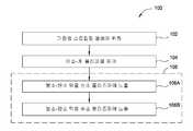
도 1은 본 발명의 일 실시예에 따른 교번하는 수소 및 산소 플라즈마들을 이용하여 붕소-탄소 막을 제거하는 방법을 예시하는 흐름도이다.
도 2는 본 발명의 일 실시예에 따른 산소 및 수소 모두를 함유하는 플라즈마를 이용하여 붕소-탄소 막을 제거하는 방법을 예시하는 흐름도이다.
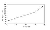
도 3a 및 도 3b는 산소 및 수소를 함유하는 플라즈마를 이용하는 경우의 에칭 레이트에 대한 챔버의 압력 및 RF 전력의 영향을 예시한다.
도 4는 본 발명의 일 실시예에 따른 수소 및 아산화 질소로부터 생성된 플라즈마를 이용하여 붕소-탄소 막을 제거하는 방법을 예시하는 흐름도이다.
도 5는 본 발명의 일 실시예에 따른 수증기로부터 생성된 플라즈마를 이용하여 붕소-탄소 막을 제거하는 방법을 예시하는 흐름도이다.
도 6은 수증기 플라즈마의 에칭 선택도(etching selectivity)를 예시한다.
이해를 용이하게 하기 위하여, 도면들에 공통인 동일한 엘리먼트들을 지정하기 위해, 가능한 경우에, 동일한 참조 번호들이 사용되었다. 일 실시예의 엘리먼트들 및 피쳐들이 추가적인 설명 없이 다른 실시예들에 유익하게 통합될 수 있다는 것이 고려된다.A more particular description of the invention, briefly summarized above, may be had by reference to the embodiments, in which the recited features of the invention can be understood in detail, some of which are illustrated in the accompanying drawings . It should be noted, however, that the appended drawings illustrate only typical embodiments of this invention and are therefore not to be considered limiting of its scope, for the invention may admit to other equally effective embodiments to be.
1 is a flow diagram illustrating a method for removing a boron-carbon film using alternating hydrogen and oxygen plasmas according to one embodiment of the present invention.
2 is a flow chart illustrating a method for removing a boron-carbon film using a plasma containing both oxygen and hydrogen according to an embodiment of the present invention.
Figures 3a and 3b illustrate the effect of chamber pressure and RF power on etch rate when using a plasma containing oxygen and hydrogen.
4 is a flow chart illustrating a method for removing a boron-carbon film using a plasma generated from hydrogen and nitrous oxide according to an embodiment of the present invention.
5 is a flow chart illustrating a method for removing a boron-carbon film using plasma generated from water vapor according to an embodiment of the present invention.
Figure 6 illustrates the etching selectivity of the water vapor plasma.
To facilitate understanding, identical reference numerals have been used, where possible, to designate identical elements that are common to the figures. It is contemplated that the elements and features of one embodiment may be advantageously incorporated into other embodiments without further explanation.
본 발명의 실시예들은 일반적으로, 수소 함유 환원제들과 조합하여 산소 함유 산화제들을 이용하여 붕소-탄소 막들을 건식 스트립핑하는 방법들에 관한 것이다. 일 실시예에서, 수소 및 산소의 교번하는 플라즈마들이 붕소-탄소 막을 제거하기 위해 사용된다. 다른 실시예에서, 공동-유동되는 산소 및 수소 플라즈마가 붕소-탄소 함유 막을 제거하기 위해 사용된다. 아산화 질소 플라즈마가 위의 산소 플라즈마들 중 어느 하나에 부가하여 또는 그에 대한 대안으로서 사용될 수 있다. 다른 실시예에서, 수증기로부터 생성된 플라즈마가 붕소-탄소 막을 제거하기 위해 사용된다. 붕소-탄소 제거 프로세스들은 또한, 붕소-탄소 막들의 제거 전에, 선택적인 폴리머 제거 프로세스를 포함할 수 있다. 폴리머 제거 프로세스는, 기판 에칭 프로세스 동안에 생성된 임의의 탄소-계 폴리머들을 붕소-탄소 막의 표면으로부터 제거하기 위해, 산소 함유 가스, 불소 함유 가스, 또는 이들의 조합으로부터 형성된 플라즈마에 붕소-탄소 막을 노출시키는 단계를 포함한다.Embodiments of the present invention generally relate to methods of dry stripping boron-carbon films using oxygen containing oxidizing agents in combination with hydrogen containing reducing agents. In one embodiment, alternating plasma of hydrogen and oxygen is used to remove the boron-carbon film. In another embodiment, a co-flowing oxygen and hydrogen plasma is used to remove the boron-carbon containing film. A nitrous oxide plasma may be used in addition to or as an alternative to any of the above oxygen plasmas. In another embodiment, a plasma generated from water vapor is used to remove the boron-carbon film. The boron-carbon removal processes may also include an optional polymer removal process prior to removal of the boron-carbon films. The polymer removal process may include exposing the boron-carbon film to a plasma formed from an oxygen-containing gas, a fluorine-containing gas, or a combination thereof to remove any carbon-based polymers generated during the substrate etch process from the surface of the boron- .
본 발명의 실시예들은 캘리포니아 산타클라라 소재의 Applied Materials, Inc.로부터 입수가능한 Producer® SE 또는 Producer® GT 챔버들에서 실시될 수 있다. 다른 제조사들에 의해 생산된 것들을 포함하는 다른 챔버들이 본 명세서에서 설명된 실시예들로부터 이익을 얻을 수 있다는 것이 고려된다.Embodiments of the present invention may be practiced in Producer SE or Producer GT chambers available from Applied Materials, Inc. of Santa Clara, California. It is contemplated that other chambers, including those produced by other manufacturers, may benefit from the embodiments described herein.
도 1은 본 발명의 일 실시예에 따른 교번하는 수소 및 산소 플라즈마를 이용하여 붕소-탄소 막을 제거하는 방법을 예시하는 흐름도(100)이다. 흐름도(100)는 동작(102)에서 시작하며, 동작(102)에서, 붕소-탄소 하드마스크와 같은 붕소-탄소 막을 위에 갖는 기판이 스트립핑 챔버 내의 기판 지지체 상에 위치된다. 기판 및 그 위의 붕소-탄소 막은 약 750 ℃ 미만, 예컨대 약 200 ℃ 내지 약 400 ℃의 온도로 가열된다. 붕소-탄소 막은, 약 2:1 또는 그 미만의 붕소 대 탄화물의 원자비를 갖는 수소화된(hydrogenated) 붕소 탄화물 또는 붕소-도핑된 탄소일 수 있다. 기판은 일반적으로, 300 밀리미터 실리콘 웨이퍼와 같은 실리콘 함유 기판이고, 그 위에 배치된 하나 또는 둘 이상의 유전체 또는 전도성 금속 층들을 가질 수 있다. 예를 들면, 기판은 그 위에 배치된 실리콘 이산화물 층을 가질 수 있으며, 그 실리콘 이산화물 층 위에는, 붕소-탄소 층이 실리콘 이산화물 층의 이전에 수행된 에칭 동안 에칭 하드마스크로서 작용하도록 배치된다. 실리콘 함유 기판들 이외의 기판들이 사용될 수 있다는 것이 고려된다.1 is a flow diagram 100 illustrating a method for removing a boron-carbon film using an alternating hydrogen and oxygen plasma in accordance with an embodiment of the present invention. Flow diagram 100 begins at
지지체 상에 기판을 위치시킨 후에, 폴리머 제거 동작(104)에서, 붕소-탄소 막 상에 위치된 탄소-계 폴리머들이 선택적으로 제거된다. 탄소-계 폴리머들은, 붕소-탄소 층이 에칭 하드마스크로서 작용하는 이전에 수행된 에칭 프로세스 동안에 붕소-탄소 층의 상측 표면 상에 생성된다. 에칭 동안에, 기판 및 그 위의 붕소-탄소 층은 기판 내로 원하는 패턴을 에칭하기 위해 C4F8과 같은 에천트(etchant)에 노출된다. 탄소와 불소의 중합(polymerization)으로 인해, 에칭 프로세스는 탄소-계 폴리머를 생성하며, 그 탄소-계 폴리머는 또한 실리콘 및/또는 산소를 포함할 수 있다. 탄소-계 폴리머는 일반적으로, 붕소-탄소 막의 더 효율적인 스트립핑을 허용하도록 더 높은 분자량의 분자들을 제거하기 위해, 스트립핑 프로세스 전에 제거된다.After positioning the substrate on the support, in the
탄소-계 폴리머는, 불소 함유 가스, 산소 함유 가스, 또는 이들의 조합으로부터 형성된 플라즈마에 탄소-계 폴리머를 노출시킴으로써, 붕소-탄소 막의 표면으로부터 제거된다. 예를 들면, 탄소-계 폴리머는, 약 100:1의 비율을 갖는 NF3 및 산소 가스로부터 형성된 플라즈마를 이용하여 제거될 수 있다. 일반적으로, 플라즈마에서 요구되는 불소의 양은 탄소-계 폴리머에 존재하는 실리콘의 양에 따라 증가한다. 특히 탄소-계 폴리머가 비교적 적은 양의 실리콘을 함유하는 경우에, 산소 함유 플라즈마가 탄소-계 폴리머를 제거할 수 있으므로, 동작(106)(아래에서 논의됨)에서의 산소 함유 플라즈마에 대한 기판의 노출로 인해, 동작(104)이 생략될 수 있다.The carbon-based polymer is removed from the surface of the boron-carbon film by exposing the carbon-based polymer to a plasma formed from a fluorine-containing gas, an oxygen-containing gas, or a combination thereof. For example, the carbon-based polymer can be removed using a plasma formed from NF3 and oxygen gas having a ratio of about 100: 1. Generally, the amount of fluorine required in the plasma increases with the amount of silicon present in the carbon-based polymer. Containing plasma at operation 106 (discussed below), especially when the carbon-based polymer contains a relatively small amount of silicon, because the oxygen-containing plasma can remove the carbon-based polymer. Due to exposure,
폴리머 제거 프로세스 동안에, 산소 가스 및 NF3 가스를 이용하여 원격으로 생성된 플라즈마가 300 밀리미터 기판당 약 1 SCCM 내지 약 15,000 SCCM, 예를 들면, 약 100 SCCM 내지 약 5,000 SCCM의 유량으로 스트립핑 챔버에 제공된다. 산소 대 NF3의 비율은 약 100:1 내지 약 1000:1이다. 스트립핑 챔버 내의 압력은 약 1 밀리토르(milliTorr) 내지 약 760 토르(Torr), 예컨대 약 4 밀리토르 내지 약 10 토르의 범위 내의 압력에서 유지되면서, 기판은 750 ℃ 미만의 온도에서 유지된다. 산소 및 NF3은 휘발성 화합물을 형성하기 위해 탄소-계 폴리머와 반응하며, 그 휘발성 화합물은 그 후에 스트립핑 챔버로부터 배기된다. 이러한 조건들 하에서, 탄소-계 폴리머는 분당 약 2,000 옹스트롬 내지 분당 약 10,000 옹스트롬의 레이트로 제거된다. 탄소-계 폴리머가 기판의 표면으로부터의 제거를 보장하기 위해 과다-에칭(over-etch)될 수 있다는 것이 고려된다.During the polymer removal process, a remotely generated plasma using oxygen gas and NF3 gas is introduced into the stripping chamber at a flow rate of from about 1 SCCM to about 15,000 SCCM per 300 millimeter substrate, for example, from about 100 SCCM to about 5,000 SCCM / RTI > The ratio of oxygen to NF3 is from about 100: 1 to about 1000: 1. The substrate is maintained at a temperature below 750 占 폚, while the pressure in the stripping chamber is maintained at a pressure in the range of about 1 milliTorr to about 760 Torr, e.g., about 4 milliTorr to about 10 Torr. Oxygen and NF3 react with the carbon-based polymer to form volatile compounds, which are then exhausted from the stripping chamber. Under these conditions, the carbon-based polymer is removed at a rate of from about 2,000 angstroms per minute to about 10,000 angstroms per minute. It is contemplated that the carbon-based polymer can be over-etched to ensure removal from the surface of the substrate.
붕소-탄소 층으로부터의 탄소-계 폴리머 층의 제거 후에, 동작(106)에서, 붕소-탄소 층이 기판의 표면으로부터 스트립핑된다. 동작(106)은 2개의 서브-동작들(106A 및 106B)을 포함한다. 서브-동작(106A)에서, 붕소-탄소 층은 산소 플라즈마와 같은 이온화된 산소 함유 화합물에 노출되고, 그 후에 후속하여, 서브-동작(106B)에서, 기판은 수소 플라즈마와 같은 이온화된 수소 함유 화합물에 노출된다. 서브-동작(106A)에서, 산소 이온들은, 챔버로부터 배기되는 휘발성 화합물(예를 들면, CO2)을 형성하기 위해 붕소-탄소 막의 탄소와 반응한다. 이온화된 산소에 대한 약 10초 내지 약 50초의 노출 후에, 탄소의 제거로 인해, 붕소-탄소 막은 막의 표면 근처에서 비교적 더 높은 농도의 붕소를 형성한다. 붕소-탄소 막의 제거 레이트는, 막의 표면 상의 이용가능한 탄소의 감소로 인해, 감소하기 시작한다. 이 시점에서, 스트립핑 챔버로의 산소 함유 화합물의 유량은 중단되고, 잔여 산소 함유 화합물은 스트립핑 챔버로부터 배기된다.After removal of the carbon-based polymer layer from the boron-carbon layer, at
서브-동작(106B)에서, 붕소-탄소 층은, 휘발성 화합물(예를 들면, B2H6)을 형성하기 위해 붕소-탄소 층에서의 붕소와 반응하는 수소 함유 화합물 플라즈마에 노출되며, 그 휘발성 화합물은 그 후에 챔버로부터 배기된다. 붕소-탄소 층은, 붕소-탄소 막이 붕소-탄소 막의 표면 근처에서 비교적 더 높은 농도의 탄소를 가질 때까지, 약 10초 내지 약 50초 동안 수소 플라즈마에 노출된다. 미리 결정된 시간 후에, 수소 가스의 유동이 중단되고, 그 후에, 서브-동작(106A)이 반복된다. 서브-동작들(106A 및 106B)을 포함하는 동작(106)은, 기판 표면으로부터 붕소-탄소 막을 충분히 제거하기 위해 원하는 양의 시간으로 반복될 수 있다.In
수소 함유 화합물 및 산소 함유 화합물 각각은 300 밀리미터 기판당 약 5 SCCM 내지 약 15,000 SCCM의 유량으로 스트립핑 챔버에 제공된다. 예를 들면, 수소 가스 및 산소 가스는 각각, 약 500 SCCM 내지 약 10,000 SCCM 및 약 250 SCCM 내지 약 5000 SCCM의 유량으로 스트립핑 챔버에 제공될 수 있다. 수소 함유 화합물 및 산소 함유 화합물은 약 100 와트 내지 약 3,000 와트의 전력, 예를 들면 약 1,000 와트 내지 약 3,000 와트를 인가하는, 13.56 ㎒에서 동작하는 RF 생성기를 이용하여 이온화된다. 스트립핑 챔버 내의 압력은 약 1 밀리토르 내지 약 760 토르, 예컨대 약 50 밀리토르 내지 약 10 토르, 또는 약 5 토르 내지 약 100 토르의 범위 내의 압력에서 유지된다.Each of the hydrogen containing compound and the oxygen containing compound is provided to the stripping chamber at a flow rate of about 5 SCCM to about 15,000 SCCM per 300 millimeter substrate. For example, hydrogen gas and oxygen gas may be provided to the stripping chamber at a flow rate of about 500 SCCM to about 10,000 SCCM and about 250 SCCM to about 5000 SCCM, respectively. The hydrogen containing compound and the oxygen containing compound are ionized using an RF generator operating at 13.56 MHz, applying from about 100 watts to about 3,000 watts of power, for example, from about 1,000 watts to about 3,000 watts. The pressure in the stripping chamber is maintained at a pressure in the range of about 1 millitorr to about 760 torr, such as about 50 millitorr to about 10 torr, or about 5 torr to about 100 torr.
산소 함유 화합물이 탄소와 반응하고, 수소 함유 화합물이 붕소와 반응하기 때문에, 각각의 화합물의 노출 시간들은, 원하는 제거 레이트를 달성하기 위해 붕소-탄소 막의 원자 조성에 기초하여 테일러링(tailor)될 수 있다는 것이 유의되어야 한다. 예를 들면, 붕소-탄소 막에서의 붕소 농도가 막에서의 탄소의 농도의 약 2배이면, 수소 노출 시간은 산소 노출 시간보다 더 클 수 있으며, 예컨대 약 2배 더 클 수 있다(플라즈마들 양자 모두가 대략 동일한 에칭 레이트를 갖는다고 가정함).Since the oxygen containing compound reacts with carbon and the hydrogen containing compound reacts with boron, the exposure times of each compound can be tailored based on the atomic composition of the boron-carbon film to achieve the desired removal rate ≪ / RTI > For example, if the boron concentration in the boron-carbon film is about twice the concentration of carbon in the film, the hydrogen exposure time may be greater than the oxygen exposure time, for example, about two times larger Assuming that all have approximately the same etch rate).
흐름도(100)는 붕소-탄소 막을 제거하기 위한 일 실시예를 예시하며; 그러나, 다른 실시예들이 또한 고려된다. 일 실시예에서, 동작들(102, 104, 및 106)은 모두 동일한 챔버에서 수행된다. 다른 실시예에서, 동작(104)은 에칭 챔버와 같은 개별 챔버에서 발생할 수 있고, 스트립핑 챔버에 기판을 위치시키기 전에 발생할 수 있다는 것이 고려된다. 다른 실시예에서, 동작(104)의 플라즈마는, 원격으로 생성되는 것에 부가하여 또는 그에 대한 대안으로서 용량성으로 커플링될 수 있거나 유도성으로 커플링될 수 있다는 것이 고려된다. 예를 들면, 용량성으로 커플링된 플라즈마는 불소 함유 가스 및 산소 함유 가스로부터 생성될 수 있다는 것이 고려된다. 대안적으로, 용량성으로 커플링된 플라즈마는 수증기 및 불활성 가스로부터 생성될 수 있다. 이러한 실시예에서, 수증기는 약 10 SCCM 내지 10,000 SCCM, 예컨대 약 4,000 SCCM의 유량으로 챔버에 도입될 수 있다. 불활성 가스는 약 3,000 SCCM의 유량으로 챔버에 제공될 수 있다.Flow diagram 100 illustrates one embodiment for removing a boron-carbon film; However, other embodiments are also contemplated. In one embodiment,
다른 실시예에서, 다른 불소 함유 가스들이 동작(104)에서 사용될 수 있다는 것이 고려된다. 예를 들면, CF4, C3F6, CHF3, CH2F2, 및 CH3F가 이용될 수 있다는 것이 고려된다. 다른 실시예에서, 동작(104)의 NF3 플라즈마, 또는 동작(106)의 산소 함유 또는 수소 함유 플라즈마들은 유도성 커플링을 통해 인-시튜로 생성될 수 있거나, 원격으로 생성될 수 있다는 것이 고려된다. 또 다른 실시예에서, 동작(106)의 산소 함유 화합물 및 수소 함유 화합물은, 아르곤, 헬륨 또는 질소와 같은 캐리어 가스를 이용하여 스트립핑 챔버로 운반될 수 있다는 것이 고려된다. 캐리어 가스들은 약 5 SCCM 내지 약 15,000 SCCM의 유량으로, 300 밀리미터 기판을 포함하는 스트립핑 챔버에 제공될 수 있다. 다른 실시예에서, 챔버는, 수소와 산소 사이의 반응을 방지하기 위해 캐리어 가스를 이용하여 서브-동작들(106A 및 106B) 사이에서 플러싱될(flushed) 수 있다는 것이 고려된다. 또 다른 실시예에서, 서브-동작(106B)이 서브-동작(106A) 전에 수행될 수 있다는 것이 고려된다.In other embodiments, it is contemplated that other fluorine containing gases may be used in
다른 실시예에서, O2, N2O, CO2, NO, 또는 NO2와 같은 산소를 제공하는 임의의 화합물이 동작(106)에서 사용될 수 있다는 것이 고려된다. 게다가, 동작(106)에서 다른 수소 함유 화합물들이 수소 가스에 부가하여 또는 그에 대한 대안들로서 사용될 수 있다는 것이 또한 고려된다. 예를 들면, 암모니아가 수소 가스에 부가하여 또는 그에 대한 대안으로서 사용될 수 있다는 것이 고려된다.In another embodiment, it is contemplated that any compound that provides oxygen such as O2 , N2 O, CO2 , NO, or NO2 may be used in
일 예에서, 약 2000 옹스트롬의 두께를 갖는 붕소-탄소 막이 7 토르의 챔버 압력 및 400 ℃의 기판 온도에서 30초 동안 1500 SCCM의 수소 플라즈마에 노출된다. 그 후에, 붕소-탄소 막은 7 토르의 챔버 압력 및 400 ℃의 기판 온도에서 30초 동안 1500 SCCM의 산소 플라즈마에 노출된다. 붕소-탄소 막은, 막이 제거될 때까지, 교번하는 수소 및 산소 플라즈마들에 더 노출된다. 붕소-탄소 막은 약 20분만에 제거되었다.In one example, a boron-carbon film having a thickness of about 2000 angstroms is exposed to a hydrogen plasma at 1500 SCCM for 30 seconds at a chamber pressure of 7 Torr and a substrate temperature of 400 占 폚. Thereafter, the boron-carbon film is exposed to an oxygen plasma of 1500 SCCM for 30 seconds at a chamber pressure of 7 Torr and a substrate temperature of 400 ° C. The boron-carbon film is further exposed to alternating hydrogen and oxygen plasma until the film is removed. The boron-carbon film was removed in about 20 minutes.
도 2는 본 발명의 일 실시예에 따른 산소 및 수소 모두를 함유하는 플라즈마를 이용하여 붕소-탄소 막을 제거하는 방법을 예시하는 흐름도(200)이다. 흐름도(200)는 동작들(102, 104, 및 206)을 포함한다. 동작들(102 및 104)은 흐름도(100)를 참조하여 설명된 동작들(102 및 104)과 유사하다. 동작(102)에서 지지체 상에 기판을 위치시키고, 동작(104)에서 탄소-계 폴리머를 제거한 후에, 동작(206)에서, 기판 및 그 위의 붕소-탄소 막은 이원자 수소와 같은 수소 함유 화합물 및 이원자 산소와 같은 산소 함유 화합물로부터 형성된 플라즈마 또는 이온화된 가스에 노출된다. 따라서, 흐름도(100)의 동작(106)이 수소 함유 및 산소 함유 플라즈마들을 교번시키는 사이클에 붕소-탄소 막을 노출시키는 반면, 동작(206)은 동시적인 수소 함유 및 산소 함유 플라즈마들에 붕소-탄소 막을 노출시킨다.2 is a flow diagram 200 illustrating a method for removing a boron-carbon film using a plasma containing both oxygen and hydrogen, in accordance with an embodiment of the present invention. The
동작(206)에서, 수소 함유 화합물 및 산소 함유 화합물은, 기판의 표면으로부터 붕소-탄소 층을 제거하기 위해, 300 밀리미터 기판당 약 5 SCCM 내지 약 15,000 SCCM의 유량으로 스트립핑 챔버에 제공된다. 예를 들면, 수소 함유 화합물 및 산소 함유 화합물은 약 200 SCCM 내지 약 4,000 SCCM의 유량으로 제공될 수 있다. 수소 함유 화합물 및 산소 함유 화합물은, 13.56 ㎒에서 동작하고 약 100 와트 내지 약 3,000 와트의 전력, 예컨대 약 1,500 와트 내지 약 2,000 와트의 전력을 인가하는 RF 생성기를 이용하여 이온화된다. 기판은 750 ℃ 미만의 온도에서, 예컨대 약 400 ℃에서 유지된다. 스트립핑 챔버 내의 압력은 일반적으로, 약 20 토르 미만, 예컨대 약 7 토르 내지 약 19 토르의 압력에서 유지된다. 약 20 토르 미만에서 챔버 압력을 유지시킴으로써, 산소 플라즈마 및 수소 플라즈마가 스트립핑 챔버 내에서 바람직하지 않게 그리고 위험하게 반응할 확률이 크게 감소된다.In
챔버 내의 수소 함유 플라즈마 및 산소 함유 플라즈마는 붕소-탄소 막과 접촉하고 반응하여, 휘발성 화합물들을 형성하며, 그 휘발성 화합물들은 그 후에 챔버로부터 배기된다. 산소가 일반적으로 붕소-탄소 막에서의 탄소와의 휘발성 화합물을 형성하고, 수소가 붕소와의 휘발성 화합물을 형성하기 때문에, 산소 대 수소(및/또는 산소 및 수소의 유량들)의 상대 비율이 원하는 제거 레이트를 달성하기 위해 붕소-탄소 막의 조성에 따라 조정될 수 있다는 것이 고려된다. 표 1은 다양한 프로세스 파라미터들을 이용하여 300 밀리미터 기판의 표면으로부터의 붕소-탄소 막의 제거 레이트에서의 변화를 예시한다.The hydrogen-containing plasma and the oxygen-containing plasma in the chamber contact and react with the boron-carbon film to form volatile compounds, which are then evacuated from the chamber. Since the oxygen generally forms volatile compounds with carbon in the boron-carbon film, and the hydrogen forms volatile compounds with boron, the relative ratio of oxygen to hydrogen (and / or oxygen and hydrogen flow rates) It is contemplated that this can be adjusted depending on the composition of the boron-carbon film to achieve the removal rate. Table 1 illustrates the change in removal rate of the boron-carbon film from the surface of a 300 millimeter substrate using various process parameters.
(와트)power
(watt)
(℃)T
(° C)
(SCCM)H2 flow rate
(SCCM)
(SCCM)O2 flow rate
(SCCM)
레이트
(Å/분)etching
Rate
(Å / min)
증가된 산소 또는 수소 유량들에 대하여, 플라즈마에서의 과잉한 산소 또는 수소는 일반적으로, 에칭 레이트에 거의 영향을 미치지 않는다. 에칭의 레이트는, 산소 또는 수소가 함께 휘발성 화합물을 형성할 수 있는, 붕소-탄소 막의 표면 상에 존재하는 붕소 또는 탄소의 양에 의해 제한되며, 일반적으로, 과잉한 프로세스 가스의 함유에 의해 크게 증가되지 않는다. 그러나, 에칭 레이트는, 프로세스 가스가 제한 반응물(limiting reactant)인 경우에 부가적인 프로세스 가스의 함유를 통해 증가될 수 있다는 것이 유의되어야 한다(예를 들면, 과잉한 반응물 위치들은 붕소-탄소 막의 표면 상에 존재한다).For increased oxygen or hydrogen flow rates, excess oxygen or hydrogen in the plasma generally has little effect on the etch rate. The rate of etching is limited by the amount of boron or carbon present on the surface of the boron-carbon film where oxygen or hydrogen can form volatile compounds together and is generally increased significantly by the inclusion of excess process gas It does not. It should be noted, however, that the etch rate may be increased through the inclusion of additional process gases in the case where the process gas is a limiting reactant (e.g., excess reactant sites are present on the surface of the boron- Lt; / RTI >
흐름도(200)는 붕소-탄소 막을 스트립핑하는 일 실시예를 예시하며; 그러나, 다른 실시예들이 또한 고려된다. 다른 실시예에서, 동작(206)에서의 산소 함유 화합물 및 수소 함유 화합물은, 300 밀리미터 기판당 15,000 SCCM 미만의 유량을 갖는, 아르곤, 헬륨, 또는 질소와 같은 캐리어 가스를 이용하여 스트립핑 챔버에 도입될 수 있다는 것이 고려된다. 처리 볼륨으로의 캐리어 가스의 함유는 붕소-탄소 막이 에칭되는 레이트를 감소시킬 수 있지만, 또한, 플라즈마 균일성 및 안정성을 증가시킬 수 있다.Flow diagram 200 illustrates one embodiment for stripping a boron-carbon film; However, other embodiments are also contemplated. In another embodiment, the oxygen containing compound and the hydrogen containing compound in
도 3a 및 도 3b는 산소 및 수소를 함유하는 플라즈마를 이용하는 경우의 에칭 레이트에 대한 챔버 압력 및 RF 전력의 영향을 예시한다. 도 3a에서, 400 ℃에서의 붕소-탄소 막이 1,000 와트의 RF 전력에서 2,000 SCCM의 수소 가스 및 1,000 SCCM의 산소 가스로부터 형성된 플라즈마를 이용하여 기판으로부터 제거되었다. 챔버 내의 압력이 증가됨에 따라, 붕소-탄소 막의 에칭 레이트가 대응하여 증가된다. 따라서, 본 명세서에서 설명된 모든 방법들에서, 붕소-탄소 막의 에칭 레이트는 챔버 내의 압력을 조정함으로써 제어될 수 있다. 도 3b에서, 400 ℃에서의 붕소-탄소 막이 2,000 SCCM의 수소 가스 및 1,000 SCCM의 산소 가스로부터 형성된 플라즈마를 이용하여 제거되었다. 챔버 압력은 9 토르에서 유지되었다. 플라즈마에 인가되는 RF 전력이 증가됨에 따라, 붕소-탄소 막의 에칭 레이트가 대응하여 증가된다.Figures 3A and 3B illustrate the effect of chamber pressure and RF power on etch rate when using a plasma containing oxygen and hydrogen. In Figure 3a, a boron-carbon film at 400 占 폚 was removed from the substrate using a plasma formed from 2,000 SCCM hydrogen gas and 1,000 SCCM oxygen gas at 1,000 watts of RF power. As the pressure in the chamber is increased, the etch rate of the boron-carbon film is correspondingly increased. Thus, in all of the methods described herein, the etch rate of the boron-carbon film can be controlled by adjusting the pressure in the chamber. In Fig. 3B, a boron-carbon film at 400 DEG C was removed using a plasma formed from 2,000 SCCM of hydrogen gas and 1,000 SCCM of oxygen gas. The chamber pressure was maintained at 9 Torr. As the RF power applied to the plasma increases, the etch rate of the boron-carbon film increases correspondingly.
도 4는 본 발명의 일 실시예에 따른 수소 및 아산화 질소로부터 생성된 플라즈마를 이용하여 붕소-탄소 막을 제거하는 방법을 예시하는 흐름도이다. 흐름도(400)는 동작들(102, 104, 및 406)을 포함한다. 동작들(102 및 104)은 흐름도(100)를 참조하여 설명된 동작들(102 및 104)과 유사하다. 동작(102)에서 지지체 상에 기판을 위치시키고, 동작(104)에서 탄소-계 폴리머를 제거한 후에, 동작(406)에서, 기판 및 그 위의 붕소-탄소 막은 수소 및 아산화 질소로부터 형성된 플라즈마에 노출된다. 따라서, 흐름도(200)가 붕소-탄소 막으로부터 탄소를 제거하기 위해 산화제로서 산소를 사용하는 반면, 흐름도(400)는 산화제로서 아산화 질소를 사용한다. 산화제로서의 아산화 질소의 사용은, 챔버 내의 압력이 증가되게 허용하고, 따라서 에칭 레이트를 증가시키면서, 산화제로서 산소를 이용하는 경우에 가능하게 일어나는 것과 같이 바람직하지 않은 반응들이 처리 환경 내에서 발생할 확률을 감소시킨다.4 is a flow chart illustrating a method for removing a boron-carbon film using a plasma generated from hydrogen and nitrous oxide according to an embodiment of the present invention. Flow diagram 400 includes
동작(406)에서, 수소 가스 및 아산화 질소 가스가, 기판의 표면으로부터 붕소-탄소 층을 제거하기 위해, 300 밀리미터 기판에 대해 약 5 SCCM 내지 약 15,000 SCCM의 유량으로 스트립핑 챔버에 제공된다. 예를 들면, 수소 가스 및 아산화 질소 가스는 각각, 약 200 SCCM 내지 약 4,000 SCCM의 유량으로 제공될 수 있다. 수소 가스 및 아산화 질소 가스는, 13.56 ㎒에서 동작하고 약 100 와트 내지 약 3,000 와트의 전력, 예컨대 약 1,500 와트 내지 약 2,000 와트의 전력을 인가하는 RF 생성기를 이용하여 이온화된다. 기판은 750 ℃ 미만의 가열기 온도에서, 예컨대 약 400 ℃에서 유지된다. 스트립핑 챔버 내의 압력은 760 토르 미만, 예컨대 약 40 토르 내지 약 60 토르에서 유지된다. 아산화 질소 플라즈마 및 수소 플라즈마는 휘발성 화합물들을 형성하기 위해 붕소-탄소 막과 반응하며, 그 휘발성 화합물들은 그 후에 챔버로부터 배기된다.In
표 2는 수소 및 아산화 질소로부터 형성된 플라즈마를 이용하여 300 밀리미터 기판의 표면으로부터 붕소-탄소 막을 제거하기 위한 일부 예시적인 프로세스 레시피들을 예시한다.Table 2 illustrates some exemplary process recipe for removing the boron-carbon film from the surface of a 300 millimeter substrate using a plasma formed from hydrogen and nitrous oxide.
(와트)power
(watt)
(℃)T
(° C)
(SCCM)H2 flow rate
(SCCM)
(SCCM)N2 O flow rate
(SCCM)
레이트
(Å/분)etching
Rate
(Å / min)
표 2에 예시된 바와 같이, 산화제로서의 아산화 질소의 사용은 일반적으로, 산화제로서 산소를 사용하는 경우보다 더 큰 에칭 레이트를 산출한다. 이는 부분적으로, 아산화 질소를 사용하는 경우에 이용될 수 있는 더 높은 챔버 압력들로 인한 것이다. 다른 실시예에서, 산화 가스가 아산화 질소와 산소의 혼합물일 수 있다는 것이 고려되며, 이 경우에, 챔버에서의 압력은 20 토르를 초과하도록 허용될 수 있다. 게다가, 흐름도(400)가 공동-유동하는 아산화 질소 및 수소 가스를 참조하여 설명되지만, 아산화 질소 및 수소 가스가 순환적인 방식으로 챔버에 독립적으로 제공되는 것이 고려된다. 또 다른 실시예에서, 탄소 이산화물이 아산화 질소에 부가하여 또는 그에 대한 대안으로서 사용될 수 있다는 것이 고려된다.As illustrated in Table 2, the use of nitrous oxide as the oxidant generally yields a greater etch rate than when using oxygen as the oxidant. This is due, in part, to higher chamber pressures that may be used in the case of using nitrous oxide. In another embodiment, it is contemplated that the oxidizing gas may be a mixture of nitrous oxide and oxygen, in which case the pressure in the chamber may be allowed to exceed 20 Torr. In addition, while the
도 5는 본 발명의 일 실시예에 따른 수증기로부터 생성된 플라즈마를 이용하여 붕소-탄소 막을 제거하는 방법을 예시하는 흐름도(500)이다. 흐름도(500)는 동작들(102, 104, 및 506)을 포함한다. 동작들(102 및 104)은 흐름도(100)를 참조하여 설명된 동작들(102 및 104)과 유사하다. 동작(102)에서 지지체 상에 기판을 위치시키고, 동작(104)에서 탄소-계 폴리머를 제거한 후에, 동작(506)에서, 기판 및 그 위의 붕소-탄소 막은 수증기로부터 형성된 플라즈마에 노출된다.5 is a flow diagram 500 illustrating a method for removing a boron-carbon film using plasma generated from water vapor in accordance with an embodiment of the present invention. Flow diagram 500 includes
동작(506)에서, 수증기는 수증기 생성기(WVG)에 의해 생성되고, 스트립핑 챔버에 제공되며, 그 스트립핑 챔버에서, 수증기는 기판의 표면으로부터 붕소-탄소 막을 에칭하기 위해 플라즈마로 점화된다. 수증기는 300 밀리미터 기판당 약 5 SCCM 내지 약 15,000 SCCM의 유량으로 스트립핑 챔버에 도입된다. 기판이 약 750 ℃ 미만, 예컨대 약 300 ℃ 내지 약 500 ℃의 온도에서 유지되면서, 챔버에서의 압력은 약 760 토르 미만, 예컨대 약 10 토르 내지 약 50 토르, 또는 약 10 토르 내지 약 760 토르에서 유지된다. 챔버로부터 배기되는 휘발성 화합물들을 형성하기 위해 붕소-탄소 막과 반응하는, 산소, 수소, 및 수산기 이온들 또는 라디칼들을 함유하는 플라즈마를 생성하기 위해, 수증기에 약 10 와트 내지 3,000 와트의 범위 내의 RF 전력이 인가된다.In
흐름도(500)는 붕소-탄소 막을 스트립핑하기 위한 일 실시예를 예시하며; 그러나, 부가적인 실시예들이 또한 고려된다. 예를 들면, 수증기가 인-시튜 스팀 생성을 통해 생성될 수 있다는 것이 고려된다. 다른 실시예에서, 산소와 수소의 비화학량적(non-stoichiometric) 조합들(예를 들면, HxOy, 여기서, x 및 y는, 양자 모두가 0보다 더 큰 비-정수들 또는 정수들일 수 있음)이 WVG로 입력될 수 있거나, WVG에 의해 생성될 수 있다는 것이 고려된다. 이러한 실시예에서, 일부 과산화 수소가 수증기 생성기에 의해 생성될 수 있다. 다른 실시예에서, 산소 가스, 헬륨 가스, 질소 가스, 아르곤 가스, 아산화 질소 가스, 및/또는 수소 가스가 수증기에 부가하여 스트립핑 챔버에 제공될 수 있다는 것이 고려된다. 이러한 실시예에서, 수소의 부가는, 특히, 탄소와 비교하여 더 높은 농도의 붕소를 함유하는 붕소-탄소 막들에서, 붕소-탄소 막의 제거 레이트를 증가시키는 것으로 발견되었다. 헬륨과 같은 다른 캐리어 가스들의 부가는, 붕소-탄소 막의 제거의 레이트를 낮추면서 동시에 에칭 균일성을 개선하는 것으로 관찰되었다. 다른 실시예에서, 실질적으로 붕소를 함유하지 않은 비정질 탄소와 같은 탄소 막을 스트립핑하기 위해 수증기가 사용될 수 있다는 것이 고려된다. 대안적으로, 실질적으로 탄소를 함유하지 않은 비정질 붕소와 같은 붕소 막을 스트립핑하기 위해 수증기가 사용될 수 있다는 것이 고려된다.Flow diagram 500 illustrates one embodiment for stripping a boron-carbon film; However, additional embodiments are also contemplated. For example, it is contemplated that water vapor may be generated via in-situ steam generation. In other embodiments, non-stoichiometric combinations of oxygen and hydrogen (e.g., Hx Oy , where x and y are both non-integers or integers greater than zero May be input to the WVG, or may be generated by the WVG. In this embodiment, some hydrogen peroxide may be produced by the steam generator. In another embodiment, it is contemplated that oxygen gas, helium gas, nitrogen gas, argon gas, nitrous oxide gas, and / or hydrogen gas may be provided to the stripping chamber in addition to steam. In this embodiment, the addition of hydrogen was found to increase the removal rate of the boron-carbon film, especially in boron-carbon films containing a higher concentration of boron compared to carbon. It has been observed that the addition of other carrier gases such as helium improves etch uniformity while lowering the rate of removal of the boron-carbon film. In another embodiment, it is contemplated that steam may be used to strip carbon films, such as amorphous carbon, which are substantially free of boron. Alternatively, it is contemplated that water vapor may be used to strip a boron film, such as amorphous boron, which is substantially free of carbon.
다른 실시예에서, 동작(506)에서, 불소 함유 가스 또는 염소 함유 가스가, 붕소-탄소 막의 에칭 레이트를 증가시키기 위해 수증기와 조합하여 이온화될 수 있다는 것이 고려된다. 이러한 실시예에서, 동작(104)은 생략될 수 있다. 불소 함유 가스 또는 염소 함유 가스는 일반적으로, 약 10 SCCM 내지 50 SCCM의 유량으로 챔버에 제공된다. 기판 상에 존재하는 유전체 물질들을 바람직하지 않게 에칭하는 것을 방지하기 위해, 불소 함유 가스 또는 염소 함유 가스의 유량은 동작(506)의 종료에 접근할 때, 테이퍼링(taper), 감소, 또는 제거된다. 동작(106)의 종료 근처에서의 유량에서의 감소는, 불소 함유 가스 또는 염소 함유 가스가 붕소-탄소 층의 제거를 돕는 메커니즘으로 인해, 노출된 유전체 물질들을 바람직하지 않게 에칭하지 않는다고 생각된다.In another embodiment, it is contemplated that, at
일반적으로, 기판 상의 유전체 물질은 이전의 에칭 프로세스 동안에 기판 내로 형성된 비아들 또는 트렌치들에서 노출되는 한편, 붕소-탄소 물질은 기판의 상측 표면 상에 노출된다. 따라서, 챔버에 진입하고 플라즈마로 점화되는 불소 함유 가스 또는 염소 함유 가스는 일반적으로, 비아들 또는 트렌치들에서의 유전체 물질과 접촉하기 전에, 붕소-탄소 층과 접촉하고 반응한다. 그러나, 붕소-탄소 막이 제거됨에 따라, 불소 함유 가스 또는 염소 함유 가스가 유전체 물질과 접촉하고 그 유전체 물질을 바람직하지 않게 제거할 확률이 증가된다. 따라서, 불소 함유 가스 또는 염소 함유 가스의 유량은, 유전체 물질을 에칭할 확률을 감소시키기 위해 붕소 함유 층의 두께가 감소함에 따라 감소된다.Generally, the dielectric material on the substrate is exposed in the vias or trenches formed into the substrate during the previous etching process, while the boron-carbon material is exposed on the upper surface of the substrate. Thus, the fluorine-containing gas or chlorine-containing gas entering the chamber and ignited by the plasma generally contacts and reacts with the boron-carbon layer before contacting the dielectric material in the vias or trenches. However, as the boron-carbon film is removed, the fluorine-containing gas or the chlorine-containing gas is in contact with the dielectric material and the probability of undesirably removing the dielectric material is increased. Accordingly, the flow rate of the fluorine-containing gas or the chlorine-containing gas is reduced as the thickness of the boron-containing layer is reduced in order to reduce the probability of etching the dielectric material.
다른 실시예에서, 용량성으로 커플링된 수증기 플라즈마를 생성하는 경우에, 챔버 내에 위치된 면판과 기판 사이의 간격은 약 20 mils 내지 약 600 mils의 범위 내에 있을 수 있다. 면판과 기판 사이의 감소된 간격은, 더 높은 압력들(예를 들면, 약 7 토르 초과) 하에서 더 큰 볼륨들의 기판들을 처리하는 경우에(예를 들면, 대면적 기판들을 처리하는 경우에) 유익하다. 약 7 토르보다 더 큰 압력들에서 기판들을 처리하는 경우에, 감소된 간격은 플라즈마 지속성을 용이하게 한다. 일 예에서, 약 30 토르에서 기판을 처리하는 경우에, 기판과 면판 사이의 간격은 약 300 mils일 수 있다. 40 토르에서, 기판과 면판 사이의 간격은 약 240 mils 내지 약 270 mils의 범위 내에 있을 수 있다. 약 50 토르의 압력에서, 기판과 면판 사이의 간격은 200 mils 미만일 수 있다.In another embodiment, when generating a capacitively coupled water vapor plasma, the spacing between the faceplate and the substrate positioned in the chamber may be in the range of about 20 mils to about 600 mils. The reduced spacing between the faceplate and the substrate is advantageous (for example, when processing large area substrates) when processing substrates of larger volumes under higher pressures (e.g., greater than about 7 Torr) Do. In the case of processing substrates at pressures greater than about 7 Torr, the reduced spacing facilitates plasma sustainability. In one example, when processing a substrate at about 30 Torr, the spacing between the substrate and the faceplate can be about 300 mils. At 40 Torr, the distance between the substrate and the faceplate can be in the range of about 240 mils to about 270 mils. At a pressure of about 50 Torr, the spacing between the substrate and the faceplate can be less than 200 mils.
표 3은 프로세스 가스 유량에서의 변화에 응답하는 붕소-탄소 막의 에칭 레이트에서의 변화를 예시한다. 표 3에서의 예들 23-30 각각은 에칭 균일성을 증가시키기 위해 캐리어 가스로서 적어도 500 SCCM의 헬륨 가스를 포함하고, 표 3에 표시된 바와 같이, 부가적인 캐리어 가스를 함유할 수 있다.Table 3 illustrates the change in etch rate of the boron-carbon film in response to changes in the process gas flow rate. Examples 23-30 in Table 3 each include at least 500 SCCM helium gas as a carrier gas to increase etch uniformity and may contain additional carrier gas, as shown in Table 3.
(와트)power
(watt)
(℃)T
(° C)
(SCCM)H2 O flow rate
(SCCM)
(SCCM)He flow
(SCCM)
(SCCM)Carrier gas
(SCCM)
레이트
(Å/분)etching
Rate
(Å / min)
표 3에 나타낸 바와 같이, 가장 높은 총 유량의 캐리어 가스(250 SCCM의 헬륨 및 750 SCCM의 아르곤)를 함유하는 예 29가 가장 낮은 에칭 레이트를 갖는다.As shown in Table 3, Example 29, which contains the highest total flow carrier gas (250 SCCM of helium and 750 SCCM of argon) has the lowest etch rate.
도 6은 수증기 플라즈마의 에칭 선택도를 예시한다. 플라즈마 A는, 1900 와트의 RF 전력을 이용하여 플라즈마로 생성된 1,000 SCCM의 수증기 및 500 SCCM의 헬륨을 포함한다. 스트립핑 챔버는 50 토르에서 유지되고, 기판은 400 ℃에서 유지된다. 플라즈마 A는 분당 약 570 옹스트롬의 레이트로 붕소-탄소 막을 에칭했고, 실리콘 산화물, 실리콘 질화물, 또는 비정질 실리콘을 에칭하지 않았다.Figure 6 illustrates the etch selectivity of a water vapor plasma. Plasma A contains 1,000 SCCM of water vapor and 500 SCCM of helium produced in a plasma using 1900 watts of RF power. The stripping chamber is maintained at 50 Torr, and the substrate is maintained at 400 占 폚. Plasma A etched the boron-carbon film at a rate of about 570 Angstroms per minute and did not etch silicon oxide, silicon nitride, or amorphous silicon.
플라즈마 B는 1900 와트의 RF 전력을 이용하여 플라즈마로 생성된 1,000 SCCM의 수증기, 250 SCCM의 헬륨, 및 150 SCCM의 수소를 포함한다. 스트립핑 챔버는 50 토르에서 유지되고, 기판은 400 ℃에서 유지된다. 플라즈마 B는 분당 약 770 옹스트롬의 레이트로 붕소-탄소 막을 에칭했고, 실리콘 산화물, 실리콘 질화물, 또는 비정질 실리콘을 에칭하지 않았다.Plasma B contains 1,000 SCCM of water vapor, 250 SCCM of helium, and 150 SCCM of hydrogen generated in the plasma using 1900 watts of RF power. The stripping chamber is maintained at 50 Torr, and the substrate is maintained at 400 占 폚. Plasma B etched the boron-carbon film at a rate of about 770 Angstroms per minute and did not etch silicon oxide, silicon nitride, or amorphous silicon.
본 명세서에서 설명된 방법들의 장점들은 기판 상에 위치된 유전체 물질들 또는 아래놓인 금속 층들을 손상시키지 않고 붕소-탄소 막들을 스트립핑하는 것을 포함한다. 스트립핑 방법들은 에칭 레이트, 뿐만 아니라, 에칭 균일성이 플라즈마 조성을 변화시킴으로써 제어되게 허용한다.Advantages of the methods described herein include stripping boron-carbon films without damaging underlying dielectric materials or underlying metal layers on the substrate. The stripping methods allow the etch rate, as well as etch uniformity, to be controlled by varying the plasma composition.
상술한 바가 본 발명의 실시예들에 관한 것이지만, 본 발명의 다른 및 추가 실시예들이 본 발명의 기본 범위로부터 벗어나지 않고 안출될 수 있으며, 본 발명의 범위는 다음의 청구범위에 의해 결정된다.While the foregoing is directed to embodiments of the present invention, other and further embodiments of the invention may be devised without departing from the basic scope thereof, and the scope thereof is determined by the claims that follow.
Claims (15)
Translated fromKorean상기 붕소-탄소 막을 위에 갖는 상기 기판을 챔버에 위치시키는 단계;
상기 붕소-탄소 막을 산소 라디칼(radical)들 또는 이온들, 및 수소 라디칼들 또는 이온들을 포함하는 플라즈마에 노출시키는 단계;
휘발성 붕소 종(species)을 형성하기 위해 상기 수소 라디칼들 또는 이온들을 상기 붕소와 반응시키는 단계;
휘발성 탄소 종을 형성하기 위해 상기 산소 라디칼들 또는 이온들을 상기 탄소와 반응시키는 단계; 및
상기 챔버로부터 상기 휘발성 붕소 종 및 상기 휘발성 탄소 종을 배기하는 단계
를 포함하고,
상기 붕소-탄소 막을 노출시키는 단계는:
HxOy를 포함하는 처리 가스를 상기 챔버에 도입하는 단계 ― x 및 y는 1보다 더 큰 비-정수들(non-integers) 또는 정수들(integers)임 ―; 및
상기 처리 가스로부터 플라즈마를 생성하는 단계
를 포함하는,
기판으로부터 붕소-탄소 막을 스트립핑하기 위한 방법.A method for stripping a boron-carbon film from a substrate,
Positioning the substrate having the boron-carbon film thereon in a chamber;
Exposing the boron-carbon film to a plasma comprising oxygen radicals or ions, and hydrogen radicals or ions;
Reacting said hydrogen radicals or ions with said boron to form a volatile boron species;
Reacting the oxygen radicals or ions with the carbon to form a volatile carbon species; And
Exhausting the volatile boron species and the volatile carbon species from the chamber
Lt; / RTI >
The step of exposing the boron-carbon film comprises:
Introducing a process gas comprising Hx Oy into the chamber, wherein x and y are non-integers or integers greater than one; And
Generating a plasma from the process gas;
/ RTI >
A method for stripping a boron-carbon film from a substrate.
상기 HxOy를 포함하는 처리 가스는 수증기를 포함하는,
기판으로부터 붕소-탄소 막을 스트립핑하기 위한 방법.The method according to claim 1,
Wherein the process gas comprising Hx Oy comprises water vapor,
A method for stripping a boron-carbon film from a substrate.
상기 붕소-탄소 막을 노출시키는 단계는:
수증기 생성기를 이용하여 수증기를 생성하는 단계;
상기 챔버 내로 상기 수증기를 유동시키는 단계; 및
RF 전력을 이용하여 상기 수증기로부터 플라즈마를 형성하는 단계
를 포함하는,
기판으로부터 붕소-탄소 막을 스트립핑하기 위한 방법.3. The method of claim 2,
The step of exposing the boron-carbon film comprises:
Generating water vapor using a water vapor generator;
Flowing the water vapor into the chamber; And
Forming a plasma from the water vapor using RF power;
/ RTI >
A method for stripping a boron-carbon film from a substrate.
상기 챔버 내의 압력은 5 토르보다 더 크고, 상기 기판은 상기 챔버 내에 위치된 면판(face plate)의 표면으로부터 600 mils 미만에 위치되는,
기판으로부터 붕소-탄소 막을 스트립핑하기 위한 방법.The method according to claim 1,
Wherein the pressure in the chamber is greater than 5 torr and the substrate is located less than 600 mils from a surface of a face plate located in the chamber,
A method for stripping a boron-carbon film from a substrate.
상기 붕소-탄소 막을 위에 갖는 상기 기판을 챔버에 위치시키는 단계;
상기 붕소-탄소 막을 산소 라디칼들 또는 이온들, 및 수소 라디칼들 또는 이온들을 포함하는 플라즈마에 노출시키는 단계;
휘발성 붕소 종을 형성하기 위해 상기 수소 라디칼들 또는 이온들을 상기 붕소와 반응시키는 단계;
휘발성 탄소 종을 형성하기 위해 상기 산소 라디칼들 또는 이온들을 상기 탄소와 반응시키는 단계; 및
상기 챔버로부터 상기 휘발성 붕소 종 및 상기 휘발성 탄소 종을 배기하는 단계를 포함하고,
상기 붕소-탄소 막을 노출시키는 단계는:
산소 함유 화합물 또는 수소 함유 화합물 중 적어도 하나 및 HxOy를 포함하는 처리 가스를 상기 챔버에 도입하는 단계 ― x 및 y는 1보다 더 큰 비-정수들 또는 정수들임 ―; 및
상기 처리 가스로부터 플라즈마를 생성하는 단계
를 포함하는,
기판으로부터 붕소-탄소 막을 스트립핑하기 위한 방법.A method for stripping a boron-carbon film from a substrate,
Positioning the substrate having the boron-carbon film thereon in a chamber;
Exposing the boron-carbon film to a plasma comprising oxygen radicals or ions, and hydrogen radicals or ions;
Reacting said hydrogen radicals or ions with said boron to form a volatile boron species;
Reacting the oxygen radicals or ions with the carbon to form a volatile carbon species; And
And exhausting the volatile boron species and the volatile carbon species from the chamber,
The step of exposing the boron-carbon film comprises:
Introducing a process gas comprising at least one of an oxygen-containing compound or a hydrogen-containing compound and Hx Oy into the chamber, wherein x and y are non-integers or integers greater than one; And
Generating a plasma from the process gas;
/ RTI >
A method for stripping a boron-carbon film from a substrate.
상기 막을 위에 갖는 상기 기판을 챔버에 위치시키는 단계;
상기 막을 산소 이온들 또는 라디칼들, 및 수소 이온들 또는 라디칼들을 포함하는 플라즈마에 노출시키는 단계 ― 상기 플라즈마는 HxOy를 포함하는 화합물로부터 형성되고, x 및 y는 1보다 더 큰 비-정수들 또는 정수들임 ― ;
상기 막을 상기 플라즈마와 접촉시킴으로써 휘발성 붕소 종을 형성하기 위해 상기 수소 라디칼들 또는 이온들을 상기 붕소와 반응시키고 그리고 휘발성 탄소 종을 형성하기 위해 상기 산소 라디칼들 또는 이온들을 상기 탄소와 반응시키는 단계; 및
상기 챔버로부터 상기 휘발성 붕소 종 및 상기 휘발성 탄소 종을 배기하는 단계
를 포함하는,
기판으로부터 붕소 및 탄소를 포함하는 막을 스트립핑하기 위한 방법.A method for stripping a film comprising boron and carbon from a substrate,
Positioning the substrate having the film thereon in a chamber;
Exposing the film to a plasma comprising oxygen ions or radicals and hydrogen ions or radicals, wherein the plasma is formed from a compound comprising Hx Oy , wherein x and y are non-integer greater than one Or integers;
Reacting the hydrogen radicals or ions with the boron to form a volatile boron species by contacting the film with the plasma and reacting the oxygen radicals or ions with the carbon to form volatile carbon species; And
Exhausting the volatile boron species and the volatile carbon species from the chamber
/ RTI >
A method for stripping a film comprising boron and carbon from a substrate.
상기 챔버 내의 압력은 5 토르보다 더 크고, 상기 기판은 상기 챔버 내에 위치된 면판의 표면으로부터 600 mils 미만에 위치되는,
기판으로부터 붕소 및 탄소를 포함하는 막을 스트립핑하기 위한 방법.The method according to claim 6,
Wherein the pressure in the chamber is greater than 5 torr and the substrate is located less than 600 mils from a surface of a faceplate positioned within the chamber,
A method for stripping a film comprising boron and carbon from a substrate.
상기 기판은 200 ℃ 내지 400 ℃의 범위 내의 온도에서 유지되는,
기판으로부터 붕소 및 탄소를 포함하는 막을 스트립핑하기 위한 방법.The method according to claim 6,
Wherein the substrate is maintained at a temperature in the range of < RTI ID = 0.0 > 200 C < / RTI &
A method for stripping a film comprising boron and carbon from a substrate.
Applications Claiming Priority (5)
| Application Number | Priority Date | Filing Date | Title |
|---|---|---|---|
| US201161485534P | 2011-05-12 | 2011-05-12 | |
| US61/485,534 | 2011-05-12 | ||
| US13/456,404US9299581B2 (en) | 2011-05-12 | 2012-04-26 | Methods of dry stripping boron-carbon films |
| US13/456,404 | 2012-04-26 | ||
| PCT/US2012/035659WO2012154429A2 (en) | 2011-05-12 | 2012-04-27 | Methods of dry stripping boron-carbon films |
Publications (2)
| Publication Number | Publication Date |
|---|---|
| KR20140036203A KR20140036203A (en) | 2014-03-25 |
| KR101682081B1true KR101682081B1 (en) | 2016-12-02 |
Family
ID=47139880
Family Applications (1)
| Application Number | Title | Priority Date | Filing Date |
|---|---|---|---|
| KR1020137031377AActiveKR101682081B1 (en) | 2011-05-12 | 2012-04-27 | Methods of dry stripping boron-carbon films |
Country Status (6)
| Country | Link |
|---|---|
| US (1) | US9299581B2 (en) |
| JP (1) | JP5933694B2 (en) |
| KR (1) | KR101682081B1 (en) |
| CN (1) | CN103443909A (en) |
| TW (1) | TWI541062B (en) |
| WO (1) | WO2012154429A2 (en) |
Families Citing this family (47)
| Publication number | Priority date | Publication date | Assignee | Title |
|---|---|---|---|---|
| US9299581B2 (en) | 2011-05-12 | 2016-03-29 | Applied Materials, Inc. | Methods of dry stripping boron-carbon films |
| US9653327B2 (en) | 2011-05-12 | 2017-05-16 | Applied Materials, Inc. | Methods of removing a material layer from a substrate using water vapor treatment |
| US20140216498A1 (en) | 2013-02-06 | 2014-08-07 | Kwangduk Douglas Lee | Methods of dry stripping boron-carbon films |
| US9190290B2 (en)* | 2014-03-31 | 2015-11-17 | Applied Materials, Inc. | Halogen-free gas-phase silicon etch |
| US9691590B2 (en)* | 2015-06-29 | 2017-06-27 | Lam Research Corporation | Selective removal of boron doped carbon hard mask layers |
| US10418243B2 (en) | 2015-10-09 | 2019-09-17 | Applied Materials, Inc. | Ultra-high modulus and etch selectivity boron-carbon hardmask films |
| US10490399B2 (en)* | 2016-03-09 | 2019-11-26 | Tokyo Electron Limited | Systems and methodologies for vapor phase hydroxyl radical processing of substrates |
| KR102139245B1 (en) | 2016-06-20 | 2020-07-29 | 어플라이드 머티어리얼스, 인코포레이티드 | Cleaning process to remove boron-carbon residues in the processing chamber at high temperatures |
| US10224224B2 (en) | 2017-03-10 | 2019-03-05 | Micromaterials, LLC | High pressure wafer processing systems and related methods |
| US10847360B2 (en) | 2017-05-25 | 2020-11-24 | Applied Materials, Inc. | High pressure treatment of silicon nitride film |
| US10622214B2 (en) | 2017-05-25 | 2020-04-14 | Applied Materials, Inc. | Tungsten defluorination by high pressure treatment |
| CN110678973B (en) | 2017-06-02 | 2023-09-19 | 应用材料公司 | Dry stripping of boron carbide hard masks |
| US10234630B2 (en) | 2017-07-12 | 2019-03-19 | Applied Materials, Inc. | Method for creating a high refractive index wave guide |
| US10269571B2 (en) | 2017-07-12 | 2019-04-23 | Applied Materials, Inc. | Methods for fabricating nanowire for semiconductor applications |
| US10179941B1 (en) | 2017-07-14 | 2019-01-15 | Applied Materials, Inc. | Gas delivery system for high pressure processing chamber |
| US10276411B2 (en) | 2017-08-18 | 2019-04-30 | Applied Materials, Inc. | High pressure and high temperature anneal chamber |
| WO2019036157A1 (en) | 2017-08-18 | 2019-02-21 | Applied Materials, Inc. | High pressure and high temperature anneal chamber |
| JP7274461B2 (en) | 2017-09-12 | 2023-05-16 | アプライド マテリアルズ インコーポレイテッド | Apparatus and method for manufacturing semiconductor structures using protective barrier layers |
| US10636675B2 (en) | 2017-09-27 | 2020-04-28 | Applied Materials, Inc. | Methods of etching metal-containing layers |
| JP7074956B2 (en)* | 2017-09-29 | 2022-05-25 | 東京エレクトロン株式会社 | Methods and systems for coating the substrate with fluid |
| US10643867B2 (en) | 2017-11-03 | 2020-05-05 | Applied Materials, Inc. | Annealing system and method |
| CN117936420A (en) | 2017-11-11 | 2024-04-26 | 微材料有限责任公司 | Gas delivery system for high pressure processing chamber |
| JP7330181B2 (en) | 2017-11-16 | 2023-08-21 | アプライド マテリアルズ インコーポレイテッド | High-pressure steam annealing treatment equipment |
| KR20200075892A (en) | 2017-11-17 | 2020-06-26 | 어플라이드 머티어리얼스, 인코포레이티드 | Condenser system for high pressure treatment systems |
| US10354875B1 (en)* | 2018-01-08 | 2019-07-16 | Varian Semiconductor Equipment Associates, Inc. | Techniques for improved removal of sacrificial mask |
| KR102649241B1 (en) | 2018-01-24 | 2024-03-18 | 어플라이드 머티어리얼스, 인코포레이티드 | Seam healing using high pressure annealing |
| SG11202008256WA (en) | 2018-03-09 | 2020-09-29 | Applied Materials Inc | High pressure annealing process for metal containing materials |
| US10714331B2 (en) | 2018-04-04 | 2020-07-14 | Applied Materials, Inc. | Method to fabricate thermally stable low K-FinFET spacer |
| US10950429B2 (en) | 2018-05-08 | 2021-03-16 | Applied Materials, Inc. | Methods of forming amorphous carbon hard mask layers and hard mask layers formed therefrom |
| US10566188B2 (en) | 2018-05-17 | 2020-02-18 | Applied Materials, Inc. | Method to improve film stability |
| US10704141B2 (en) | 2018-06-01 | 2020-07-07 | Applied Materials, Inc. | In-situ CVD and ALD coating of chamber to control metal contamination |
| US10748783B2 (en) | 2018-07-25 | 2020-08-18 | Applied Materials, Inc. | Gas delivery module |
| CN112514051A (en) | 2018-07-27 | 2021-03-16 | 应用材料公司 | 3D NAND etching |
| WO2020031224A1 (en)* | 2018-08-06 | 2020-02-13 | 株式会社日立ハイテクノロジーズ | Plasma treatment method and plasma ashing device |
| US10675581B2 (en) | 2018-08-06 | 2020-06-09 | Applied Materials, Inc. | Gas abatement apparatus |
| WO2020086288A1 (en)* | 2018-10-26 | 2020-04-30 | Mattson Technology, Inc. | Water vapor based fluorine containing plasma for removal of hardmask |
| CN112640065B (en) | 2018-10-30 | 2024-10-01 | 应用材料公司 | Method for etching structures for semiconductor applications |
| US11049728B2 (en)* | 2018-10-31 | 2021-06-29 | Entegris, Inc. | Boron-doped amorphous carbon hard mask and related methods |
| WO2020101935A1 (en) | 2018-11-16 | 2020-05-22 | Applied Materials, Inc. | Film deposition using enhanced diffusion process |
| CN109546012B (en)* | 2018-11-23 | 2021-10-26 | 京东方科技集团股份有限公司 | Organic film etching method and display substrate display area circuit repairing method |
| WO2020117462A1 (en) | 2018-12-07 | 2020-06-11 | Applied Materials, Inc. | Semiconductor processing system |
| US11901222B2 (en) | 2020-02-17 | 2024-02-13 | Applied Materials, Inc. | Multi-step process for flowable gap-fill film |
| KR102851412B1 (en) | 2020-03-26 | 2025-08-26 | 어플라이드 머티어리얼스, 인코포레이티드 | Catalytic formation of boron and carbon films |
| WO2022026822A1 (en) | 2020-07-30 | 2022-02-03 | Entegris, Inc. | Method for removing hard masks |
| US11955318B2 (en) | 2021-03-12 | 2024-04-09 | Applied Materials, Inc. | Ash rate recovery method in plasma strip chamber |
| CN114645281B (en)* | 2022-04-06 | 2023-11-24 | 岭南师范学院 | Method for removing carbon film on surface of metal workpiece |
| US12057320B2 (en) | 2022-10-03 | 2024-08-06 | RASIRO, Inc. | Hydrogen peroxide plasma etch of ashable hard mask |
Citations (4)
| Publication number | Priority date | Publication date | Assignee | Title |
|---|---|---|---|---|
| US20020045355A1 (en) | 2000-01-29 | 2002-04-18 | Samsung Electronics Co., Ltd. | Method of manufacturing a semiconductor device having a silicide layer |
| JP2003133290A (en) | 2001-10-26 | 2003-05-09 | Seiko Epson Corp | Resist stripping apparatus, resist stripping method, and semiconductor device manufacturing method |
| US20060003582A1 (en) | 2004-06-30 | 2006-01-05 | Hynix Semiconductor Inc. | Method for fabricating semiconductor device |
| US20080115808A1 (en) | 2006-11-20 | 2008-05-22 | Applied Materials, Inc. | In-situ chamber cleaning for an rtp chamber |
Family Cites Families (19)
| Publication number | Priority date | Publication date | Assignee | Title |
|---|---|---|---|---|
| US4975144A (en) | 1988-03-22 | 1990-12-04 | Semiconductor Energy Laboratory Co., Ltd. | Method of plasma etching amorphous carbon films |
| JPH05217965A (en)* | 1992-01-22 | 1993-08-27 | Nec Corp | Manufacture of semiconductor device |
| US6165891A (en) | 1999-11-22 | 2000-12-26 | Chartered Semiconductor Manufacturing Ltd. | Damascene structure with reduced capacitance using a carbon nitride, boron nitride, or boron carbon nitride passivation layer, etch stop layer, and/or cap layer |
| US20020086547A1 (en) | 2000-02-17 | 2002-07-04 | Applied Materials, Inc. | Etch pattern definition using a CVD organic layer as an anti-reflection coating and hardmask |
| US6352921B1 (en) | 2000-07-19 | 2002-03-05 | Chartered Semiconductor Manufacturing Ltd. | Use of boron carbide as an etch-stop and barrier layer for copper dual damascene metallization |
| US6413852B1 (en) | 2000-08-31 | 2002-07-02 | International Business Machines Corporation | Method of forming multilevel interconnect structure containing air gaps including utilizing both sacrificial and placeholder material |
| TW476135B (en) | 2001-01-09 | 2002-02-11 | United Microelectronics Corp | Manufacture of semiconductor with air gap |
| US6541397B1 (en) | 2002-03-29 | 2003-04-01 | Applied Materials, Inc. | Removable amorphous carbon CMP stop |
| US6884733B1 (en) | 2002-08-08 | 2005-04-26 | Advanced Micro Devices, Inc. | Use of amorphous carbon hard mask for gate patterning to eliminate requirement of poly re-oxidation |
| US6939794B2 (en) | 2003-06-17 | 2005-09-06 | Micron Technology, Inc. | Boron-doped amorphous carbon film for use as a hard etch mask during the formation of a semiconductor device |
| US7105431B2 (en)* | 2003-08-22 | 2006-09-12 | Micron Technology, Inc. | Masking methods |
| US7407893B2 (en) | 2004-03-05 | 2008-08-05 | Applied Materials, Inc. | Liquid precursors for the CVD deposition of amorphous carbon films |
| US7638440B2 (en) | 2004-03-12 | 2009-12-29 | Applied Materials, Inc. | Method of depositing an amorphous carbon film for etch hardmask application |
| US20060199393A1 (en) | 2004-06-29 | 2006-09-07 | Taiwan Semiconductor Manufacturing Co., Ltd. | H20 plasma and h20 vapor methods for releasing charges |
| KR100637689B1 (en) | 2005-04-21 | 2006-10-24 | 주식회사 하이닉스반도체 | Contact Formation Method of Semiconductor Device Using Solid Phase Epitaxy Method |
| KR20070081649A (en) | 2006-02-13 | 2007-08-17 | 삼성전자주식회사 | Manufacturing Method of Semiconductor Device |
| US8337950B2 (en) | 2007-06-19 | 2012-12-25 | Applied Materials, Inc. | Method for depositing boron-rich films for lithographic mask applications |
| US9299581B2 (en) | 2011-05-12 | 2016-03-29 | Applied Materials, Inc. | Methods of dry stripping boron-carbon films |
| US9653327B2 (en) | 2011-05-12 | 2017-05-16 | Applied Materials, Inc. | Methods of removing a material layer from a substrate using water vapor treatment |
- 2012
- 2012-04-26USUS13/456,404patent/US9299581B2/enactiveActive
- 2012-04-27WOPCT/US2012/035659patent/WO2012154429A2/enactiveApplication Filing
- 2012-04-27KRKR1020137031377Apatent/KR101682081B1/enactiveActive
- 2012-04-27JPJP2014510355Apatent/JP5933694B2/enactiveActive
- 2012-04-27CNCN201280015166XApatent/CN103443909A/enactivePending
- 2012-05-02TWTW101115611Apatent/TWI541062B/enactive
Patent Citations (4)
| Publication number | Priority date | Publication date | Assignee | Title |
|---|---|---|---|---|
| US20020045355A1 (en) | 2000-01-29 | 2002-04-18 | Samsung Electronics Co., Ltd. | Method of manufacturing a semiconductor device having a silicide layer |
| JP2003133290A (en) | 2001-10-26 | 2003-05-09 | Seiko Epson Corp | Resist stripping apparatus, resist stripping method, and semiconductor device manufacturing method |
| US20060003582A1 (en) | 2004-06-30 | 2006-01-05 | Hynix Semiconductor Inc. | Method for fabricating semiconductor device |
| US20080115808A1 (en) | 2006-11-20 | 2008-05-22 | Applied Materials, Inc. | In-situ chamber cleaning for an rtp chamber |
Also Published As
| Publication number | Publication date |
|---|---|
| CN103443909A (en) | 2013-12-11 |
| TW201247312A (en) | 2012-12-01 |
| JP2014516205A (en) | 2014-07-07 |
| KR20140036203A (en) | 2014-03-25 |
| US20120285492A1 (en) | 2012-11-15 |
| JP5933694B2 (en) | 2016-06-15 |
| WO2012154429A2 (en) | 2012-11-15 |
| TWI541062B (en) | 2016-07-11 |
| WO2012154429A3 (en) | 2013-04-25 |
| US9299581B2 (en) | 2016-03-29 |
Similar Documents
| Publication | Publication Date | Title |
|---|---|---|
| KR101682081B1 (en) | Methods of dry stripping boron-carbon films | |
| US10510518B2 (en) | Methods of dry stripping boron-carbon films | |
| KR102148035B1 (en) | Removal of polysilicon and native oxide with high selectivity | |
| CN101983417B (en) | Plasma etching method | |
| CN101536155B (en) | Plasma dielectric etch process including in-situ backside polymer removal for low-dielectric constant material | |
| KR101476435B1 (en) | Multi-layer resist plasma etch method | |
| CN1271688C (en) | Plasma etching of silicon carbide | |
| US20080153306A1 (en) | Dry photoresist stripping process and apparatus | |
| KR101391347B1 (en) | Etching gas | |
| KR20160075358A (en) | Selective nitride etch | |
| TWI284370B (en) | Use of hypofluorites, fluoroperoxides, and/or fluorotrioxides as oxidizing agent in fluorocarbon etch plasmas | |
| CN109690735B (en) | Stripping method for high aspect ratio structures | |
| KR20020061001A (en) | Plasma processing of tungsten using a gas mixture comprising a fluorinated gas and oxygen | |
| JP2013030778A (en) | Method for bilayer resist plasma etch | |
| US11158517B2 (en) | Selective plasma etching of silicon oxide relative to silicon nitride by gas pulsing | |
| EP2159829A2 (en) | Selective etching of silicon dioxide compositions | |
| TW200839866A (en) | Methods for recess etching | |
| KR101877827B1 (en) | Etching gas and etching method | |
| TW202025290A (en) | Dry etching method | |
| JP2000208488A (en) | Etching method | |
| KR100856005B1 (en) | How to Etch a Carbon-Containing Silicon Oxide Film | |
| KR102765856B1 (en) | Dry etching method and method for manufacturing semiconductor devices | |
| US20020155724A1 (en) | Dry etching method and apparatus | |
| CN117012635A (en) | Silicide etching method | |
| JPWO2020129725A1 (en) | Etching method with halogen fluoride, semiconductor manufacturing method |
Legal Events
| Date | Code | Title | Description |
|---|---|---|---|
| PA0105 | International application | Patent event date:20131126 Patent event code:PA01051R01D Comment text:International Patent Application | |
| PG1501 | Laying open of application | ||
| A201 | Request for examination | ||
| A302 | Request for accelerated examination | ||
| PA0201 | Request for examination | Patent event code:PA02012R01D Patent event date:20160621 Comment text:Request for Examination of Application | |
| PA0302 | Request for accelerated examination | Patent event date:20160621 Patent event code:PA03022R01D Comment text:Request for Accelerated Examination | |
| E902 | Notification of reason for refusal | ||
| PE0902 | Notice of grounds for rejection | Comment text:Notification of reason for refusal Patent event date:20160628 Patent event code:PE09021S01D | |
| E701 | Decision to grant or registration of patent right | ||
| PE0701 | Decision of registration | Patent event code:PE07011S01D Comment text:Decision to Grant Registration Patent event date:20161025 | |
| GRNT | Written decision to grant | ||
| PR0701 | Registration of establishment | Comment text:Registration of Establishment Patent event date:20161128 Patent event code:PR07011E01D | |
| PR1002 | Payment of registration fee | Payment date:20161129 End annual number:3 Start annual number:1 | |
| PG1601 | Publication of registration | ||
| PR1001 | Payment of annual fee | Payment date:20211026 Start annual number:6 End annual number:6 | |
| PR1001 | Payment of annual fee | Payment date:20221025 Start annual number:7 End annual number:7 | |
| PR1001 | Payment of annual fee | Payment date:20241029 Start annual number:9 End annual number:9 |