KR101681768B1 - Convection device and electric oven comprising the same - Google Patents
Convection device and electric oven comprising the sameDownload PDFInfo
- Publication number
- KR101681768B1 KR101681768B1KR1020080087606AKR20080087606AKR101681768B1KR 101681768 B1KR101681768 B1KR 101681768B1KR 1020080087606 AKR1020080087606 AKR 1020080087606AKR 20080087606 AKR20080087606 AKR 20080087606AKR 101681768 B1KR101681768 B1KR 101681768B1
- Authority
- KR
- South Korea
- Prior art keywords
- heater
- convection
- bracket
- back plate
- delete delete
- Prior art date
- Legal status (The legal status is an assumption and is not a legal conclusion. Google has not performed a legal analysis and makes no representation as to the accuracy of the status listed.)
- Active
Links
Images


Classifications
- F—MECHANICAL ENGINEERING; LIGHTING; HEATING; WEAPONS; BLASTING
- F24—HEATING; RANGES; VENTILATING
- F24C—DOMESTIC STOVES OR RANGES ; DETAILS OF DOMESTIC STOVES OR RANGES, OF GENERAL APPLICATION
- F24C15/00—Details
- F24C15/32—Arrangements of ducts for hot gases, e.g. in or around baking ovens
- F24C15/322—Arrangements of ducts for hot gases, e.g. in or around baking ovens with forced circulation
- F24C15/325—Arrangements of ducts for hot gases, e.g. in or around baking ovens with forced circulation electrically-heated
- F—MECHANICAL ENGINEERING; LIGHTING; HEATING; WEAPONS; BLASTING
- F24—HEATING; RANGES; VENTILATING
- F24C—DOMESTIC STOVES OR RANGES ; DETAILS OF DOMESTIC STOVES OR RANGES, OF GENERAL APPLICATION
- F24C15/00—Details
- F24C15/32—Arrangements of ducts for hot gases, e.g. in or around baking ovens
- F24C15/322—Arrangements of ducts for hot gases, e.g. in or around baking ovens with forced circulation
- F—MECHANICAL ENGINEERING; LIGHTING; HEATING; WEAPONS; BLASTING
- F24—HEATING; RANGES; VENTILATING
- F24C—DOMESTIC STOVES OR RANGES ; DETAILS OF DOMESTIC STOVES OR RANGES, OF GENERAL APPLICATION
- F24C7/00—Stoves or ranges heated by electric energy
- F24C7/04—Stoves or ranges heated by electric energy with heat radiated directly from the heating element
- F—MECHANICAL ENGINEERING; LIGHTING; HEATING; WEAPONS; BLASTING
- F24—HEATING; RANGES; VENTILATING
- F24C—DOMESTIC STOVES OR RANGES ; DETAILS OF DOMESTIC STOVES OR RANGES, OF GENERAL APPLICATION
- F24C7/00—Stoves or ranges heated by electric energy
- F24C7/06—Arrangement or mounting of electric heating elements
- F—MECHANICAL ENGINEERING; LIGHTING; HEATING; WEAPONS; BLASTING
- F24—HEATING; RANGES; VENTILATING
- F24C—DOMESTIC STOVES OR RANGES ; DETAILS OF DOMESTIC STOVES OR RANGES, OF GENERAL APPLICATION
- F24C7/00—Stoves or ranges heated by electric energy
- F24C7/08—Arrangement or mounting of control or safety devices
- F24C7/087—Arrangement or mounting of control or safety devices of electric circuits regulating heat
- H—ELECTRICITY
- H05—ELECTRIC TECHNIQUES NOT OTHERWISE PROVIDED FOR
- H05B—ELECTRIC HEATING; ELECTRIC LIGHT SOURCES NOT OTHERWISE PROVIDED FOR; CIRCUIT ARRANGEMENTS FOR ELECTRIC LIGHT SOURCES, IN GENERAL
- H05B3/00—Ohmic-resistance heating
- H05B3/40—Heating elements having the shape of rods or tubes
- H05B3/42—Heating elements having the shape of rods or tubes non-flexible
- H05B3/48—Heating elements having the shape of rods or tubes non-flexible heating conductor embedded in insulating material
Landscapes
- Engineering & Computer Science (AREA)
- Chemical & Material Sciences (AREA)
- Combustion & Propulsion (AREA)
- Mechanical Engineering (AREA)
- General Engineering & Computer Science (AREA)
- Electric Stoves And Ranges (AREA)
- Resistance Heating (AREA)
Abstract
Translated fromKoreanDescription
Translated fromKorean본 발명은 조리기기에 관한 것으로, 보다 상세하게는, 컨벡션장치 및 이를 포함하는 전기오븐에 관한 것이다.BACKGROUND OF THE INVENTION 1. Field of the Invention The present invention relates to a cooking appliance, and more particularly, to a convection device and an electric oven including the same.
전기오븐이란 전기를 사용하여 음식물을 가열하는 조리기기이다. 이와 같은 전기오븐에는, 음식물이 조리되는 오븐실 및 상기 오븐실에서의 음식물의 조리를 위한 적어도 1개의 히터가 구비된다. 예를 들면, 상기 오븐실의 내부의 음식물을 복사가열하는 히터, 상기 오븐실의 내부의 음식물을 대류가열하는 튜브히터 등이 상기 전기오븐에 구비될 수 있다.An electric oven is a cooking appliance that uses electricity to heat food. The electric oven includes an oven chamber in which food is cooked and at least one heater for cooking food in the oven chamber. For example, the electric oven may include a heater for radiating and heating food inside the oven chamber, and a tube heater for heating the food in the oven chamber by convection.
그러나 종래 기술에 의한 전기오븐에는 다음과 같은 문제점이 발생된다.However, the electric oven according to the prior art has the following problems.
먼저 종래에는 상기 튜브히터로 시즈히터가 주로 사용된다. 그러나 시즈히터의 경우에는 출력이 다른 종류의 히터, 예를 들면, 튜브히터에 비하여 상대적으로 저출력으로 동작된다. 따라서 상기 오븐실의 내부에서 상기 튜브히터에 의한 음식물의 조리효율이 저하되는 동시에 조리시간이 증가되는 단점이 발생된다.In the prior art, a sipe heater is mainly used as the tube heater. However, in the case of a sheath heater, the output is operated at a relatively low output as compared to other types of heaters, for example, tube heaters. Therefore, the cooking efficiency of the food by the tube heater is lowered in the oven chamber and the cooking time is increased.
또한 상기 튜브히터의 경우에는 통상적으로 상기 오븐실의 후면 또는 측면에 설치된다. 따라서 상기 튜브히터로 튜브히터를 사용하는 경우에는, 상기 튜브히터를 그 외관을 형성하는 튜브의 손상을 방지할 수 있도록 고정하여야 하지만, 현재까지는 이와 같은 상기 튜브히터의 고정구조가 제안되지 않고 있다.Further, in the case of the tube heater, it is usually installed on the rear surface or the side surface of the oven chamber. Therefore, when the tube heater is used as the tube heater, the tube heater should be fixed so as to prevent damage to the tubes forming the outer tube. However, up to now, the tube heater fixing structure has not been proposed.
본 발명은 상술한 바와 같은 종래 기술에 의한 문제점을 해결하기 위한 것으로, 본 발명의 목적은 보다 효율적으로 음식물을 조리할 수 있도록 구성되는 컨벡션장치 및 이를 포함하는 전기오븐을 제공하는 것이다.SUMMARY OF THE INVENTION It is an object of the present invention to provide a convection device and an electric oven including the convection device.
본 발명의 다른 목적은, 컨벡션히터로 사용되는 튜브히터의 손상을 최소화할 수 있도록 구성되는 컨벡션장치 및 이를 포함하는 전기오븐을 제공하는 것이다.It is another object of the present invention to provide a convection apparatus and an electric oven including the convection apparatus, which are configured to minimize damage to a tube heater used as a convection heater.
상술한 바와 같은 목적을 달성하기 위한 본 발명의 실시예에 의하면, 본 발명은 오븐실과 연통되며 컨벡션 커버와 백 플레이트에 의해서 형성되는 컨벡션챔버; 상기 컨벡션챔버의 내부에 설치되고, 튜브 및 상기 튜브의 내부에 구비되는 열선을 포함하며, 그 단부가 상기 백 플레이트의 후면을 관통하는 컨벡션히터; 상기 컨벡션챔버의 내부에 설치되고, 상기 컨벡션히터의 열을 상기 오븐실의 내부로 대류전달하기 위한 공기의 흐름을 형성하는 컨벡션팬; 상기 컨벡션히터의 일측이 고정되고, 상기 백플레이트를 관통하여 상기 백플레이트의 외부로 돌출되는 히터브라켓; 및 상기 컨벡션히터의 단부는 상기 백플레이트에 형성되는 한 쌍의 히터관통공을 관통하고, 상기 히터브라켓의 일측은 상기 백플레이트에서 상기 한 쌍의 히터관통공 사이에 형성되는 브라켓관통슬롯을 관통하고, 상기 히터브라켓의 일측이 상기 브라켓관통슬롯을 관통한 상태에서 상기 히터 브라켓의 고정리브가 상기 백플레이트에 체결되며, 상기 각 히터관통공의 직경은 상기 컨벡션 히터의 직경보다 더 크게 형성되고, 상기 컨벡션히터의 단부에는 핀치부가 형성되며, 상기 히터브라켓의 양쪽 끝단부에 핀치부가 지지되는 한 쌍의 히터 안착부가 형성된다.
또한, 상기 컨벡션히터의 단부로부터 이격되는 상기 컨벡션히터의 일측을 지지하는 히터서포터;를 더 포함하며, 상기 히터서포터는 상기 컨벡션히터의 직경보다 큰 직경을 가지는 히터지지부를 구비한다.
또한, 상기 고정리브는, 상기 백플레이트에 밀착된다.
또한, 상기 한 쌍의 히터관통공 및 브라켓관통슬롯은 서로 연통된다.
또한, 상기 히터브라켓은, 상기 히터안착부에 안착된 상기 컨벡션히터를 고정시키는 히터고정부를 더 포함한다.
본 발명의 또 다른 실시예에 의하면, 본 발명은 음식물을 조리하기 위한 오븐실이 구비되는 캐비티; 상기 캐비티를 선택적으로 개폐하는 도어; 및 상기 오븐실에 구비되고, 상기 오븐실로 음식물의 조리를 위하여 열을 제공하는 제 1 항, 제 2 항, 제 4 항, 제 6 항 및 제 7 항 중 어느 한 항의 컨벡션장치; 를 포함한다.According to an aspect of the present invention, there is provided an oven comprising: a convection chamber communicating with an oven chamber and formed by a convection cover and a back plate; A convection heater installed inside the convection chamber, the convection heater including a tube and a heat line provided inside the tube, the end of the convection heater passing through the back surface of the back plate; A convection fan installed inside the convection chamber and forming a flow of air for conveying the heat of the convection heater to the inside of the oven chamber; A heater bracket fixed to one side of the convection heater and protruding from the back plate through the back plate; And an end of the convection heater passes through a pair of heater through holes formed in the back plate, and one side of the heater bracket penetrates a bracket through slot formed between the pair of heater through holes in the back plate A fixing rib of the heater bracket is fastened to the back plate in a state in which one side of the heater bracket passes through the bracket passing slot, the diameter of each heater through hole is formed to be larger than the diameter of the convection heater, A pinch portion is formed at an end portion of the heater, and a pair of heater seating portions are formed at both ends of the heater bracket.
The heater supporter may further include a heater supporter for supporting one side of the convection heater spaced from the end of the convection heater, wherein the heater supporter includes a heater support having a diameter larger than the diameter of the convection heater.
Further, the fixed rib is in close contact with the back plate.
The pair of heater through holes and the bracket through slots are communicated with each other.
The heater bracket may further include a heater fixing unit for fixing the convection heater mounted on the heater mounting part.
According to another embodiment of the present invention, there is provided a cooking device comprising: a cavity provided with an oven chamber for cooking food; A door selectively opening and closing the cavity; And a convection device according to any one of claims 1, 2, 4, 6, and 7 that is provided in the oven chamber and provides heat to the oven chamber for cooking food. .
삭제delete
삭제delete
삭제delete
삭제delete
본 발명에 의하면, 튜브히터에 의한 보다 효율적인 음식물의 조리가 가능해지는 동시에 튜브히터의 손상이 방지되는 이점이 있다.According to the present invention, it is possible to cook foods more efficiently by the tube heater, and at the same time, the tube heater is prevented from being damaged.
이하에서는 본 발명에 의한 전기오븐의 실시예를 첨부된 도면을 참조하여 보다 상세하게 설명한다.Hereinafter, embodiments of an electric oven according to the present invention will be described in detail with reference to the accompanying drawings.
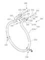
도 1은 본 발명에 의한 전기오븐의 실시예를 보인 정면도이다.1 is a front view showing an embodiment of an electric oven according to the present invention.
도 1을 참조하면, 오븐(100)의 캐비티(110)의 내부에는 오븐실(111)이 구비된다. 상기 오븐실(111)은 실질적으로 음식물의 조리가 이루어지는 곳이다. 그리고 상기 오븐실(111)은 도어(미도시)에 의하여 선택적으로 개폐된다. 상기 도어는, 예를 들면, 상기 캐비티(110)에 그 하단을 중심으로 상단이 상하로 회동하는 풀-다운(Pull-Down) 방식으로 상기 오븐실(111)을 개폐할 수 있다.Referring to FIG. 1, an
그리고 상기 오븐실(111)의 후면에는 컨벡션장치(200)가 구비된다. 상기 컨벡션장치(200)는 상기 오븐실(111)의 내부로 고온의 공기를 대류시켜서 음식물을 조리시키는 역할을 한다.A
도 2는 본 발명의 실시예를 구성하는 컨벡션장치를 보인 사시도이고, 도 3는 본 발명의 실시예를 구성하는 컨벡션장치를 보인 분해사시도이며, 도 4는 본 발명의 실시예를 구성하는 컨벡션장치의 일요부를 확대하여 보인 사시도이고, 도 5는 본 발명의 실시예를 구성하는 컨벡션장치의 다른 요부를 확대하여 보인 사시도이며, 도 6은 본 발명의 실시예를 구성하는 컨벡션장치의 이면을 보인 사시도이다.FIG. 2 is a perspective view showing a convection apparatus constituting an embodiment of the present invention, FIG. 3 is an exploded perspective view showing a convection apparatus constituting an embodiment of the present invention, FIG. 6 is a perspective view showing the back surface of the convection apparatus according to the embodiment of the present invention. FIG. 6 is a perspective view showing the convex portion of the convection apparatus according to the embodiment of the present invention. to be.
도 2 내지 도 6을 참조하면, 컨벡션장치(200)는, 컨벡션커버(210), 컨벡션히 터(220), 컨벡션팬(260) 및 컨벡션모터(270)를 포함한다.2 to 6, the
상기 컨벡션커버(210)는 상기 컨벡션히터(220) 및 컨벡션팬(260)이 설치되는 컨벡션챔버(201)를 형성한다. 보다 상세하게는, 상기 컨벡션커버(210)는 상기 오븐실(111)의 후면을 형성하는 백플레이트(120)의 전면으로부터 전방으로 소정의 간격만큼 이격되게 형성된다. 따라서 상기 백플레이트(120)의 전면과 상기 컨벡션커버(210)의 이면 사이에 상기 컨벡션챔버(201)가 형성된다.The
본 실시예에서는, 상기 컨벡션커버(210)가, 전면부(211), 상면부(212), 하면부(213) 및 2개의 플랜지부(214)를 포함한다. 상기 전면부(211)는 대략 장방형으로 판상으로 형성된다. 그리고 상기 상면부(212) 및 하면부(213)는 각각 상기 전면부(211)의 상하단에서 상향 또는 하향경사지게 후방으로 연장된다. 상기 플랜지부(214)는 각각 상기 상면부(212) 및 하면부(213)의 선단에서 상기 전면부(211)와 평행되도록 상방 또는 하방으로 연장된다. 상기 플랜지부(214)는 각각 상기 백플레이트(120)의 전면에 밀착되어 고정된다.The
그리고 상기 컨벡션커버(210)에는 흡기구(215) 및 개구부(216)가 형성된다. 상기 흡기구(215)는 상기 오븐실(111)의 내부의 공기가 상기 컨벡션챔버(201)의 내부로 흡입되는 입구역할을 한다. 상기 개구부(216)는 상기 컨벡션히터(220)에서 발생되는 빛 및 열을 상기 오븐실(111)의 내부로 전달하는 역할을 한다. 상기 흡기구(215)는 상기 컨벡션팬(260)에 대응되는 상기 전면부(211)의 일부, 즉 상기 컨벡션히터(220)의 내부에 해당하는 상기 전면부(211)의 일부가 절개되어 형성된다. 또한 상기 개구부(216)는 상기 컨벡션히터(220)의 외부에 해당하는 상기 전면 부(211)의 일부가 절개되어 형성된다. 이에 대해서는 상기 컨벡션히터(220) 및 컨벡션팬(260)에 대한 설명에서 다시 설명하기로 한다. 그리고 본 실시예에서, 상기 흡기구(215)는 전체적으로 원형을 이루고, 상기 개구부(216)는 전체적으로 링형상을 이루게 된다. 그러나 상기 흡기구(215) 및 개구부(216)의 형상이 이에 한정되는 것은 아니다.The
또한 상기 백플레이트(120) 및 컨벡션커버(210)에는 제1 및 제2공기안내부(121)(217)가 각각 구비된다. 상기 제1 및 제2공기안내부(121)(217)는 상기 흡기구(215)를 통하여 흡입되는 공기가 상기 컨벡션히터(220)와 보다 효율적으로 접촉되도록 하는 역할을 한다. 본 실시예에서는, 상기 제1공기안내부(121)는, 수평방향으로의 상기 컨벡션히터(220)의 사영에 대응하는 형상으로 상기 백플레이트(120)의 일부가 후방으로 함몰되어 형성된다. 그리고 상기 제2공기안내부(217)는, 상기 전면부(211)의 일부가 상기 컨벡션히터(220)의 사영에 대응하는 직경을 가지는 링형상으로 함몰되어 형성된다. 이때 상기 제1 및 제2공기안내부(121)(217)는, 각각 동일한 두께로 함몰된다. 따라서 상기 제1공기안내부(121)의 전면 및 상기 제2공기안내부(217)의 이면 사이의 간격은 상기 컨벡션챔버(201)의 전후간격과 동일하게 된다.The
그리고 상기 컨벡션커버(210)에는 다수개의 제1관통공(218)이 형성된다. 보다 상세하게는, 상기 제1관통공(218)은 상기 플랜지부(214)의 양측단부에 각각 형성된다. 상기 제1관통공(218)은 상기 컨벡션커버(210)를 상기 백플레이트(120)에 고정시키기 위한 제1체결구(S1)가 관통하는 곳이다.A plurality of first through
한편 본 실시예에서는, 상기 플랜지부(214)가 상기 백플레이트(120)의 전면에 밀착된 상태에서, 상기 전면부(211)의 이면은 상기 백플레이트(120)의 전면으로부터 소정의 간격만큼 이격된다. 따라서 상기 전면부(211)의 양측단부 및 상기 백플레이트(120)의 전면 사이에 해당하는 상기 컨벡션챔버(201)의 양측에는, 상기 컨벡션히터(220)의 내부의 공기가 상기 오븐실(111)의 내부로 배출되는 배기구(219)가 형성된다.The back face of the
상기 백플레이트(120)에는, 2개의 히터관통공(122) 및 1개의 브라켓관통슬롯(123)이 구비된다. 상기 히터관통공(122)은 상기 컨벡션히터(220)의 양단부가 관통하는 곳이다. 그리고 상기 브라켓관통슬롯(123)은 후술할 히터브라켓(230)이 관통하는 곳이다. 본 실시예에서는, 상기 히터관통공(122) 및 브라켓관통슬롯(123)이, 서로 연통되도록 상기 백플레이트(120)의 일부가 절개되어 형성된다.The
그리고 상기 백플레이트(120)에는 축관통공(124)이 형성된다. 상기 축관통공(124)은 후술할 모터축(271)이 관통하는 곳이다.An
또한 상기 백플레이트(120)에는 제1 내지 제4체결공(125)(126)(127)(128)이 형성된다. 상기 제1체결공(125)은 상기 컨벡션커버(210)의 고정을 위하여 상기 제1관통공(218)을 관통한 상기 제1체결구(S1)가 체결되는 곳이다. 상기 제2 및 제3체결공(127)은, 각각 후술할 히터브라켓(230) 또는 히터서포터(240)의 고정을 위하여 제2체결구(S2) 또는 제3체결구(S3)가 체결되는 곳이다. 상기 제4체결공(128)은 상기 컨벡션모터(270)의 고정을 위한 제4체결구(S4)가 체결되는 곳이다.Further, the
상기 컨벡션히터(220)는 실질적으로 상기 오븐실(111)에서의 음식물의 조리 를 위한 빛 및 열을 발생시키는 역할을 한다. 예를 들면, 상기 컨벡션히터(220)로 유리관 및 그 내부에 구비되는 열선을 포함하는 석영관히터나 할로겐히터와 같은 튜브히터가 사용될 수 있다. 이와 같은 튜브히터는 종래에 컨벡션히터로 사용되는 시즈히터에 비하여 상대적으로 고출력의 히터이다.The
그리고 상기 컨벡션히터(220)에서 발생되는 빛은 상기 개구부(216)를 통하여 상기 오븐실(111)의 내부로 전달된다. 상기 컨벡션히터(220)에서 발생되는 열은 상기 오븐실(111)의 내부로 대류, 전도 및 복사에 의하여 전달된다. 보다 상세하게는, 상기 컨벡션히터(220)에서 발생되는 열은 상기 오븐실(111)의 내부 및 상기 컨벡션챔버(201)의 내부를 순환하는 공기를 가열함으로써, 상기 오븐실(111)의 내부로 대류된다. 또한 상기 컨벡션히터(220)에서 발생되는 열의 일부는 상기 컨벡션커버(210)를 통하여 상기 오븐실(111)의 내부로 전도된다. 그리고 상기 컨벡션히터(220)에서 발생되는 열의 나머지는 상기 개구부(216)를 통하여 상기 오븐실(111)의 내부로 복사된다. 그리고 도 4에 도시된 바와 같이, 상기 튜브히터(220)는 튜브(221), 필라멘트(223), 2개의 절연부(224), 2개의 터미널(225), 연결부(226) 및 2개의 로드(227)를 포함한다.Light generated in the
상기 튜브(221)는 상기 컨벡션히터(220)의 외관을 형성하는 것이다. 그리고 상기 튜브(221)로는, 예를 들면, 대략 말굽 또는 오메가(Ω)형상으로 형성되는 석영관튜브(quartz tube)가 사용될 수 있다. 보다 상세하게는, 상기 튜브(221)는, 전체적으로 원형의 개곡선(opend curve)으로 형성되는 발열부(221A) 및 상기 발열부(221A)의 양단에서 연장되는 지지부(221B)를 포함한다. 상기 지지부(221B)는 상 기 발열부(221A)가 위치되는 가상의 평면에 직교되게 위치된다. 보다 상세하게는, 상기 발열부(221A)는 상기 제1 및 제2공기안내부(121)(217) 사이에 위치된다. 이때 상기 발열부(221A)가 위치되는 가상의 평면은 상기 백플레이트(120)의 전면과 평행을 이룬다. 그리고 상기 지지부(221B)는, 상기 백플레이트(120), 보다 상세하게는 상기 히터관통공(122) 각각 관통한다.The
그리고 상기 지지부(221B)에는 핀치부(222)가 각각 구비된다. 상기 핀치부(222)는 상기 튜브(221)의 내부를 밀봉하는 동시에 상기 필라멘트(223)의 양단 및 절연부(224)를 고정시키는 역할을 한다.The
한편 상기 필라멘트(223)는 상기 튜브(221)의 내부에 구비된다. 그리고 상기 필라멘트(223)는 전류를 인가받아서 실질적으로 빛 및 열을 발생시킨다. 상기 필라멘트(223)로는, 예를 들면, 탄소필라멘트가 사용될 수 있다. 본 실시예에서는, 상기 필라멘트(223)가 상기 발열부(221A)에 해당하는 상기 튜브(221)의 내부에만 위치된다. 따라서 실질적으로, 상기 발열부(221A)에 해당하는 부분에서만, 빛 및 열이 발생될 것이다.On the other hand, the
상기 절연부(224)는 상기 컨벡션히터(220)의 양단부를 절연시키는 역할을 한다. 상기 절연부(224)는 상기 핀치부(222)에 의하여 고정된다.The insulating portion 224 serves to insulate both ends of the
상기 터미널(225), 연결부(226) 및 로드(227)는 상기 필라멘트(223)에 전류를 공급하는 역할을 한다. 이를 위하여 상기 터미널(225)은 상기 절연부(224)를 관통하여 상기 튜브(221)의 외부로 연장된다. 그리고 상기 연결부(226)는 상기 필라멘트(223)의 양단에 각각 연결되고, 상기 로드(227)는 상기 터미널(225)과 연결 부(226)를 연결시킨다.The terminal 225, the connecting
상기 컨벡션히터(220)는, 1개의 히터브라켓(230) 및 적어도 1개의 히터서포터(240)에 의하여 상기 컨벡션챔버(201)의 내부에 고정된다. 본 실시예에서는, 상기 컨벡션히터(220)의 고정을 위하여 2개의 상기 히터서포터(240)가 사용되지만, 그 이하 또는 이상의 개수의 상기 히터서포터(240)가 사용될 수도 있다.The
상기 히터브라켓(230)은 실질적으로 상기 지지부(221B)를 지지한다. 도 4에 도시된 바와 같이, 상기 히터브라켓(230)에는, 2개의 히터안착부(231), 2개의 히터고정부(233) 및 1개의 고정리브(235)가 구비된다.The
상기 히터안착부(231)는 상기 히터브라켓(230)의 양측단부에 구비된다. 그리고 상기 히터안착부(231)에는, 상기 핀치부(223)를 포함하는 상기 지지부(221B)가 안착된다. 상기 히터안착부(231)는 상기 핀치부(223)를 포함하는 상기 지지부(221B)의 저면에 대응하는 형상으로 형성된다.The
상기 히터고정부(233)는 상기 지지부(221B)가 상기 히터안착부(231)에 안착된 상태에서 임으로 이동되는 것을 방지하기 위한 것이다. 상기 히터고정부(233)는 실질적으로 상기 지지부(221B)가 상기 히터안착부(231)에 안착된 상태에서 상기 핀치부(223)의 상면에 밀착된다. 예를 들면, 상기 히터고정부(233)는 상기 히터브라켓(230)의 양단부, 즉 상기 히터안착부(231)의 외측단부에서 각각 외측으로 연장된다. 그리고 상기 히터고정부(233)는, 상기 히터안착부(231)에 상기 지지부(221B)가 안착된 상태에서, 상기 핀치부(223)의 상면에 밀착되도록 밴딩될 수 있다.The
상기 고정리브(235)는 상기 히터브라켓(230)의 후단부에 구비된다. 상기 고정리브(235)는 상기 히터브라켓(230)을 상기 백플레이트(120)의 전면에 고정하기 위한 것이다. 상기 고정리브(235)는 상기 히터브라켓(230)의 후단에 대략 직교되게 연장되어 상기 백플레이트(120)의 전면에 밀착된다. 상기 고정리브(235)에는 상기 제2체결구(S2)가 관통되는 제2관통공(237)이 형성된다.The fixing
상기 히터서포터(240)는 상기 발열부(221A)를 지지하기 위한 것이다. 상기 히터서포터(240)는 소정의 길이의 바아를 소정의 형상으로 밴딩하여 형성된다. 상기 히터서포터(240)는 소정의 탄성력을 가질 수 있는 금속재질로 형성될 수 있다. 상기 히터서포터(240)의 탄성력은 상기 컨벡션히터(220)의 설치 및 지지를 위한 것이다. 그리고 도 5에 도시된 바와 같이, 상기 히터서포터(240)에는, 1개의 히터지지부(241), 2개의 연장부(243) 및 2개의 고정부(245)가 구비된다.The
상기 히터지지부(241)는, 상기 컨벡션히터(220)의 직경보다 큰 직경을 가지는 원형으로 형성된다. 그리고 상기 히터지지부(241)의 양단부는 서로 소정의 간격만큼 이격된다. 상기 히터지지부(241)의 내부에는 상기 발열부(221A)가 위치된다. 상기 히터지지부(241)의 직경이 상기 컨벡션히터(220)의 직경보다 큰 값을 가지는 것은, 상기 발열부(221A)와 상기 히터지지부(241) 사이의 접촉은 최소화하면서 상기 발열부(221A)의 위치이동을 방지하기 위한 것이다. 따라서 상기 히터지지부(241)에 의하여 상기 발열부(221A)가 임의로 위치이동되는 현상은 방지되는 동시에 상기 컨벡션히터(220)를 구성하는 튜브가 손상되는 현상은 최소화할 수 있게 된다.The
그리고 상기 연장부(243)는 상기 히터지지부(241)의 양단부로부터 각각 연장된다. 상기 연장부(243)는 실질적으로 상기 히터지지부(241)의 양단부와 상기 고정부(245)를 각각 연결시키는 상기 발열부(225)를 탄성지지하는 역할을 한다. 따라서 본 실시예에서는, 상기 연장부(243)가 각각 L자형상으로 형성되어 서로 소정의 간격만큼 이격되지만, 상기 연장부(243)의 형상은 이에 한정되지 않는다.The
상기 고정부(245)는 상기 연장부(243)의 일단부에서 각각 연장된다. 따라서 상기 고정부(245)도 상기 연장부(243)와 동일하게 서로 소정의 간격만큼 이격될 것이다. 이와 같이 상기 고정부(245)가 서로 소정의 간격만큼 이격됨으로써, 상기 컨벡션히터(220)는 상기 고정부(245) 사이의 공간을 통하여 상기 히터지지부(241)의 내부에 위치될 수 있다. 상기 고정부(245)는 상기 히터서포터(240)를 상기 오븐실(111)의 후면 내측에 고정하기 위한 것이다. 이를 위하여 상기 고정부(245)에는 상기 제3체결공(127)에 체결되는 상기 제3체결구(S3)가 관통하는 제3관통공(247)이 형성된다.The fixing
한편 상기 컨벡션히터(220)는 전원연결부(250)에 의하여 전원을 공급받는다. 도 4에 도시된 바와 같이, 상기 전원연결부(250)는, 제1커넥터(251), 제2커넥터(253) 및 리드와이어(255)를 포함한다.Meanwhile, the
상기 제1커넥터(251)는 상기 터미널(225)에 연결되고, 상기 제2커넥터(253)는 상기 오븐(100)의 전원부(미도시) 연결된다. 물론 상기 제2커넥터(253)는 상기 전원부에 직접 연결되거나 상기 전원부에 연결되는 별개의 연결부재, 예를 들면, 소켓 등에 연결될 수 있다. 그리고 상기 리드와이어(255)는 상기 제1 및 제2커넥 터(251)(253)를 연결한다. 한편 상기 전원연결부(250)는, 상기 컨벡션히터(220)가 설치된 상태, 즉 상기 컨벡션히터(220)가 상기 히터브라켓(230) 및 히터서포터(240)에 의하여 상기 컨벡션챔버(201)의 내부에 고정된 상태에서 상기 컨벡션히터(220)에 결합된다. 즉 상기 컨벡션히터(220)가 상기 히터관통공(122)을 관통한 상태에서 상기 터미널(225)에 상기 제1커넥터(251)가 연결된다.The
그리고 다시 도 3을 참조하면, 상기 컨벡션팬(260)은, 상기 컨벡션히터(220), 보다 상세하게는 상기 발열부(221A)의 내부에 위치되도록 상기 컨벡션챔버(201)의 내부에 설치된다. 다시 말하면, 상기 컨벡션히터(220)는 상기 컨벡션팬(260)의 외주연에 인접되게 위치되는 것이다. 상기 컨벡션팬(260)은, 상기 오븐실(111)의 내부의 공기가 상기 흡기구(215)를 통하여 상기 컨벡션챔버(201)의 내부로 흡입되고, 상기 컨벡션히터(220)에 의하여 가열된 상기 컨벡션챔버(201)의 내부의 공기가 상기 배기구(219)를 통하여 상기 오븐실(111)의 내부로 배출되는 공기의 흐름을 형성한다.3, the
또한 상기 컨벡션모터(270)는 상기 백플레이트(120)의 후면에 설치된다. 상기 컨벡션모터(270)는 상기 컨벡션팬(260)의 회전을 위한 구동력을 제공한다. 이를 위하여 상기 컨벡션모터(270)에는 모터축(271)이 구비된다. 상기 모터축(271)은 상기 축관통공(124)을 관통하여 상기 컨벡션챔버(201)의 내부로 돌출되어 상기 컨벡션팬(260)과 결합된다. 그리고 상기 컨벡션모터(270)는 모터브라켓(273)에 장착된 상태로 상기 백플레이트(120)의 후면에 고정된다. 상기 모터브라켓(273)에는 상기 제4체결공(128)에 체결되는 상기 제4체결구(S4)가 관통하는 제4관통공(275)이 형성된다.The
이하에서는 본 발명에 의한 전기오븐의 실시예를 제작하는 과정을 보다 상세하게 설명한다.Hereinafter, a process of manufacturing an embodiment of the electric oven according to the present invention will be described in detail.
먼저 컨벡션모터(270)를 백플레이트(120)의 후면에 설치한다. 상기 컨벡션모터(270)는 모터브라켓(273)에 장착된 상태에서, 상기 모터브라켓(273)의 제4관통공(275)을 관통한 제4체결구(S4)가 상기 백플레이트(120)의 제4체결공(128)에 체결됨으로써 설치된다. 이때 상기 컨벡션모터(270)의 모터축(271)은 상기 백플레이트(120)의 축관통공(124)을 관통한다.First, the
그리고 상기 모터축(271)의 선단에 컨벡션팬(260)을 결합시킨다. 상기 컨벡션팬(260)의 결합은, 후술할 컨벡션히터(220)를 고정한 다음에 이루어질 수도 있다.The
다음으로 컨벡션히터(220)를 상기 백플레이트(120)의 전면에 히터브라켓(230) 및 히터서포터(240)를 이용하여 고정시킨다. 보다 상세하게는, 상기 컨벡션히터(220)의 지지부(221B)를 통하여 상기 히터서포터(240)가 상기 컨벡션히터(220)의 발열부(221A) 상에 위치되도록 한다. 다음으로 상기 컨벡션히터(220)의 지지부(221B)를 히터브라켓(230)의 히터안착부(231)에 안착시킨다. 그리고 상기 히터브라켓(230)의 히터고정부(233)를 밴딩함으로써, 상기 지지부(221B)를 상기 히터브라켓(230)에 고정시킨다.Next, the
이와 같은 상태에서, 상기 지지부(221B)를 상기 백플레이트(120)의 히터관통공(122)을 관통시킨다. 이때 상기 지지부(221B)가 고정된 상기 히터안착부(231) 및 히터고정부(233)는 각각 상기 히터관통공(122) 또는 상기 백플레이트(120)의 브라켓관통슬롯(123)을 관통한다. 또한 상기 히터브라켓(230)의 고정리브(235)는 상기 백플레이트(120)의 전면에 밀착된다. 그리고 제2체결구(S2)를 상기 히터브라켓(230)의 제2관통공(237)을 관통하여 상기 백플레이트(120)의 제2체결공(126)에 체결시킴으로써, 상기 히터브라켓(230)이 상기 백플레이트(120)에 고정된다.In this state, the
다음으로 상기 히터서포터(240)를 이동시켜서, 상기 히터서포터(240)를 설계된 소정의 위치, 즉 상기 히터서포터(240)의 제3관통공(247)과 상기 백플레이트(120)의 제3체결공(127)이 서로 연통되는 위치에 위치시킨다. 그리고 상기 히터서포터(240)의 제3관통공(247)을 관통한 제3체결구(S3)를 상기 백플레이트(120)의 제3체결공(127)에 체결함으로써, 상기 히터서포터(240)가 고정된다.The
그리고 상기 컨벡션히터(220)의 지지부(221B)가 상기 히터관통공(122)을 관통한 상태에서, 상기 컨벡션히터(220)의 터미널(225)에 전원연결부(250)의 제1커넥터(251)를 연결한다. 한편 상기 전원연결부(250)의 제2커넥터(253)는 전원부에 연결되는 소켓에 연결된다. 따라서 상기 전원연결부(250)에 의하여 상기 컨벡션히터(220)에 전류가 인가될 수 있게 된다.The
마지막으로, 상기 백플레이트(120)의 전면에 컨벡션커버(210)를 고정시킨다. 보다 상세하게는, 상기 컨벡션커버(210)의 플랜지부(214)를 상기 백플레이트(120)의 전면에 밀착시킨다. 이때 상기 컨벡션커버(210)의 제1관통공(218)은 상기 백플레이트(120)의 제1체결공(125)과 연통되게 위치된다. 그리고 상기 컨벡션커버(210)의 제1관통공(218)을 관통한 제1체결구(S1)가 상기 백플레이트(120)의 제1 체결공(125)에 체결됨으로써, 상기 컨벡션커버(210)가 상기 백플레이트(120)에 고정된다.Finally, the
다음으로 본 발명에 의한 전기오븐의 실시예에서 오븐실의 내부의 공기의 흐름을 첨부된 도면을 참조하여 보다 상세하게 설명한다.Next, the flow of air inside the oven chamber in the embodiment of the electric oven according to the present invention will be described in detail with reference to the accompanying drawings.
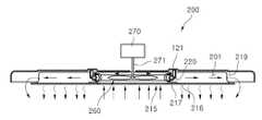
도 7은 본 발명에 의한 오븐의 실시예에서 오븐실의 내부의 공기의 흐름을 보인 횡단면도이다.7 is a cross-sectional view showing the flow of air inside the oven chamber in the embodiment of the oven according to the present invention.
도 7을 참조하면, 사용자가 컨벡션장치(200)를 이용하여 오븐실(111)에서의 음식물을 조리하기 위하여 조작신호를 입력하면, 상기 컨벡션히터(220)가 온동작된다. 이와 동시에 컨벡션모터(270)가 구동하면 이에 의하여 컨벡션팬(260)이 회전한다. 그리고 상기 컨벡션팬(260)이 회전하면, 상기 오븐실(111)의 내부의 공기가 흡기구(215)를 통하여 컨벡션챔버(201)의 내부로 흡입된다.Referring to FIG. 7, when the user inputs an operation signal to cook food in the
상기 컨벡션챔버(201)의 내부로 흡입된 공기는 상기 컨벡션히터(220)와 접촉하여 가열된다. 그런데 본 실시예에서는, 공기안내부(121)(217)에 의하여 상기 흡기구(215)를 통하여 흡입된 공기가 상기 컨벡션히터(220)와 보다 효율적으로 접촉할 수 있게 된다. 보다 상세하게는, 상기 흡기구(215)를 통하여 흡입되어 상기 컨벡션챔버(201)의 내부를 유동하는 공기는 상기 공기안내부(121)(217)에 의하여 그 유동이 간섭되어 유동속도가 감소된다. 따라서 상기 컨벡션챔버(201)의 내부를 유동하는 공기가 상기 컨벡션히터(220)에 의하여 보다 효율적으로 가열될 수 있게 되는 것이다.The air sucked into the inside of the
그리고 이와 같이 상기 컨벡션히터(220)에 의하여 가열된 공기는, 상기 컨벡 션팬(260)의 계속적인 구동에 의하여 배기구(219)를 통하여 상기 오븐실(111)의 내부로 배출된다. 따라서 상기 컨벡션히터(220)에서 발생되는 열이 상기 오븐실(111)의 내부로 대류되어 음식물을 가열하게 된다.The air heated by the
한편 상기 컨벡션히터(220)에서 발생되는 열의 일부는 컨벡션커버(210)를 통하여 상기 오븐실(111)의 내부로 직접 전도되거나 개구부(216)를 통하여 상기 오븐실(111)의 내부로 복사된다. 따라서 상기 컨벡션히터(220)에 의하여 발생되는 열은, 상기 오븐실(111)의 내부로 전도 및 복사되어 상기 오븐실(111)의 내부의 음식물을 가열하기도 한다.A part of the heat generated in the
또한 상기 컨벡션히터(220)가 동작하면 빛도 발생하게 된다. 그리고 이와 같은 상기 컨벡션히터(220)의 빛은 상기 개구부(216)를 통하여 상기 오븐실(111)의 내부로 전달된다. 따라서 사용자는 상기 컨벡션장치(200)의 동작여부를 용이하게 식별할 수 있게 된다.When the
이와 같은 본 발명의 기본적인 기술적 사상의 범주 내에서, 당업계의 통상의 지식을 가진 자에게 있어서는 다른 많은 변형이 가능함은 물론이고, 본 발명의 권리범위는 첨부한 특허청구범위에 기초하여 해석되어야 할 것이다.While the present invention has been particularly shown and described with reference to exemplary embodiments thereof, it is evident that many alternatives, modifications, and variations will be apparent to those skilled in the art in light of the above teachings. will be.
이상에서 설명한 바와 같이 구성되는 본 발명에 의한 컨벡션장치 및 이를 포함하는 전기오븐에 의하면 다음과 같은 효과를 기대할 수 있게 된다.According to the convection device and the electric oven including the same as described above, the following effects can be expected.
먼저 본 발명에서는, 오븐실의 내부의 음식물을 가열하기 위한 컨벡션히터로 고출력의 튜브히터가 사용된다. 따라서 전기오븐에 의한 보다 효율적이고 신속한 음식물의 조리가 가능하게 된다.First, in the present invention, a high output tube heater is used as a convection heater for heating the food in the oven chamber. Thus, it is possible to cook the food more efficiently and quickly by the electric oven.
또한 본 발명에서는, 상기 컨벡션히터가 히터브라켓 및 히터홀더에 의하여 컨벡션챔버의 내부에 고정된다. 따라서 상기 컨벡션히터의 손상이 최소화됨으로써, 보다 안전하게 전기오븐을 사용할 수 있게 된다.Further, in the present invention, the convection heater is fixed to the inside of the convection chamber by the heater bracket and the heater holder. Therefore, the damage of the convection heater is minimized, so that the electric oven can be used more safely.
그리고 본 발명에서는, 상기 컨벡션히터가 상기 컨벡션챔버의 내부에 고정된 상태에서 전원열결부에 의하여 전원부에 연결된다. 따라서 상기 컨벡션히터를 상기 전원부에 연결하는 과정에서, 상기 컨벡션히터가 손상되는 현상을 방지할 수 있게 된다.In the present invention, the convection heater is fixed to the inside of the convection chamber, and is connected to the power source part by the power source heat part. Therefore, it is possible to prevent the convection heater from being damaged in the process of connecting the convection heater to the power source unit.
도 1은 본 발명에 의한 전기오븐의 실시예를 보인 정면도.1 is a front view showing an embodiment of an electric oven according to the present invention;
도 2는 본 발명의 실시예를 구성하는 컨벡션장치를 보인 사시도.FIG. 2 is a perspective view showing a convection apparatus constituting an embodiment of the present invention. FIG.
도 3는 본 발명의 실시예를 구성하는 컨벡션장치를 보인 분해사시도.3 is an exploded perspective view showing a convection apparatus constituting an embodiment of the present invention.
도 4는 본 발명의 실시예를 구성하는 컨벡션장치의 일요부를 확대하여 보인 사시도.FIG. 4 is an enlarged perspective view of a part of a convection apparatus constituting an embodiment of the present invention; FIG.
도 5는 본 발명의 실시예를 구성하는 컨벡션장치의 다른 요부를 확대하여 보인 사시도.FIG. 5 is an enlarged perspective view of another essential part of a convection device constituting an embodiment of the present invention; FIG.
도 6은 본 발명의 실시예를 구성하는 컨벡션장치의 이면을 보인 사시도.6 is a perspective view showing a rear surface of a convection device constituting an embodiment of the present invention.
도 7은 본 발명에 의한 오븐의 실시예에서 오븐실의 내부의 공기의 흐름을 보인 횡단면도.7 is a cross-sectional view showing the flow of air inside the oven chamber in the embodiment of the oven according to the present invention.
Claims (21)
Translated fromKoreanPriority Applications (4)
| Application Number | Priority Date | Filing Date | Title |
|---|---|---|---|
| KR1020080087606AKR101681768B1 (en) | 2008-09-05 | 2008-09-05 | Convection device and electric oven comprising the same |
| EP09168227.8AEP2161508B1 (en) | 2008-09-05 | 2009-08-20 | Cooker |
| CN2009101681894ACN101666513B (en) | 2008-09-05 | 2009-09-03 | Cooker |
| US12/554,169US8413647B2 (en) | 2008-09-05 | 2009-09-04 | Cooker |
Applications Claiming Priority (1)
| Application Number | Priority Date | Filing Date | Title |
|---|---|---|---|
| KR1020080087606AKR101681768B1 (en) | 2008-09-05 | 2008-09-05 | Convection device and electric oven comprising the same |
Publications (2)
| Publication Number | Publication Date |
|---|---|
| KR20100028742A KR20100028742A (en) | 2010-03-15 |
| KR101681768B1true KR101681768B1 (en) | 2016-12-02 |
Family
ID=41426180
Family Applications (1)
| Application Number | Title | Priority Date | Filing Date |
|---|---|---|---|
| KR1020080087606AActiveKR101681768B1 (en) | 2008-09-05 | 2008-09-05 | Convection device and electric oven comprising the same |
Country Status (4)
| Country | Link |
|---|---|
| US (1) | US8413647B2 (en) |
| EP (1) | EP2161508B1 (en) |
| KR (1) | KR101681768B1 (en) |
| CN (1) | CN101666513B (en) |
Families Citing this family (16)
| Publication number | Priority date | Publication date | Assignee | Title |
|---|---|---|---|---|
| KR100889132B1 (en)* | 2007-04-12 | 2009-03-17 | 엘지전자 주식회사 | Oven |
| WO2009091145A2 (en)* | 2008-01-03 | 2009-07-23 | Lg Electronics Inc. | Cooker and controlling method for the same |
| KR101626156B1 (en)* | 2009-05-20 | 2016-05-31 | 엘지전자 주식회사 | Cooker |
| CN102370430B (en)* | 2010-08-25 | 2016-03-02 | 乐金电子(天津)电器有限公司 | Multifunctional oven |
| KR101520612B1 (en)* | 2013-04-30 | 2015-05-15 | 동부대우전자 주식회사 | Cooking apparatus |
| KR101564505B1 (en)* | 2014-04-03 | 2015-10-29 | 엘지전자 주식회사 | Cooking appliance |
| US20160187001A1 (en)* | 2014-12-31 | 2016-06-30 | Indesit Company S.P.A. | Oven |
| CN104739230A (en)* | 2015-02-05 | 2015-07-01 | 宁波方太厨具有限公司 | Inner container heating type steam box |
| KR101749116B1 (en)* | 2015-05-08 | 2017-06-20 | 엘지전자 주식회사 | cooking appliance |
| KR101672634B1 (en)* | 2015-05-26 | 2016-11-03 | 엘지전자 주식회사 | Cooking appliance |
| WO2019032876A1 (en) | 2017-08-09 | 2019-02-14 | Sharkninja Operating Llc | Cooking device and components thereof |
| WO2021019824A1 (en)* | 2019-07-31 | 2021-02-04 | シャープ株式会社 | Heating cooker |
| US12140320B2 (en)* | 2020-07-29 | 2024-11-12 | Electrolux Home Products, Inc. | Oven cavity wrapper having a structural embossment and associated convection features |
| FR3150089A1 (en) | 2023-06-26 | 2024-12-27 | Seb S.A. | Cooking appliance |
| FR3150087A1 (en) | 2023-06-26 | 2024-12-27 | Seb S.A. | Cooking appliance |
| FR3150088A1 (en) | 2023-06-26 | 2024-12-27 | Seb S.A. | Cooking appliance |
Citations (1)
| Publication number | Priority date | Publication date | Assignee | Title |
|---|---|---|---|---|
| KR200349859Y1 (en)* | 2004-02-27 | 2004-05-12 | 엘지전자 주식회사 | Electric oven range |
Family Cites Families (18)
| Publication number | Priority date | Publication date | Assignee | Title |
|---|---|---|---|---|
| US3531626A (en)* | 1967-05-29 | 1970-09-29 | Anthony Olff | Electrical device for visually checking credit cards |
| US5857079A (en)* | 1994-12-23 | 1999-01-05 | Lucent Technologies Inc. | Smart card for automatic financial records |
| US6008478A (en)* | 1996-12-05 | 1999-12-28 | Whirlpool Corporation | Heating element support system for oven |
| JPH11287460A (en) | 1998-04-03 | 1999-10-19 | Matsushita Electric Ind Co Ltd | Cooker |
| KR100302903B1 (en)* | 1998-04-08 | 2001-11-22 | 윤종용 | Heater supporting device of microwave oven |
| KR100395559B1 (en)* | 1999-05-29 | 2003-08-25 | 삼성전자주식회사 | Microwave oven having a heater |
| US6521870B2 (en) | 2001-01-11 | 2003-02-18 | General Electric Company | Thermal/convection oven including halogen lamps |
| US6831255B1 (en)* | 2003-09-11 | 2004-12-14 | Maytag Corporation | Combination radiant/convection cooking system for an electric oven |
| KR100808860B1 (en)* | 2004-07-23 | 2008-03-03 | 삼성전자주식회사 | Heating cooker |
| CN1779349A (en)* | 2004-11-26 | 2006-05-31 | 乐金电子(天津)电器有限公司 | Microwave oven with quartz tube heater |
| JP2006244781A (en)* | 2005-03-01 | 2006-09-14 | Matsushita Electric Ind Co Ltd | Heating device |
| US8901462B2 (en)* | 2005-07-14 | 2014-12-02 | Lg Electronics Inc. | Heating unit and method of manufacturing the same |
| KR101249863B1 (en)* | 2005-10-31 | 2013-04-05 | 삼성전자주식회사 | Cooking Apparatus |
| KR100774169B1 (en)* | 2005-11-17 | 2007-11-07 | 엘지전자 주식회사 | Heating device and steam generator and home appliance using it |
| KR100688016B1 (en)* | 2005-12-02 | 2007-02-27 | 엘지전자 주식회사 | Electric cooker with heater unit |
| KR100858721B1 (en)* | 2006-11-17 | 2008-09-17 | 엘지전자 주식회사 | Microwave Cooking Device |
| CN201014589Y (en)* | 2007-02-12 | 2008-01-30 | 广东格兰仕集团有限公司 | Microwave oven |
| JP4536763B2 (en)* | 2007-09-11 | 2010-09-01 | パナソニック株式会社 | Heating device with steam generation function |
- 2008
- 2008-09-05KRKR1020080087606Apatent/KR101681768B1/enactiveActive
- 2009
- 2009-08-20EPEP09168227.8Apatent/EP2161508B1/enactiveActive
- 2009-09-03CNCN2009101681894Apatent/CN101666513B/ennot_activeExpired - Fee Related
- 2009-09-04USUS12/554,169patent/US8413647B2/ennot_activeExpired - Fee Related
Patent Citations (1)
| Publication number | Priority date | Publication date | Assignee | Title |
|---|---|---|---|---|
| KR200349859Y1 (en)* | 2004-02-27 | 2004-05-12 | 엘지전자 주식회사 | Electric oven range |
Also Published As
| Publication number | Publication date |
|---|---|
| US8413647B2 (en) | 2013-04-09 |
| KR20100028742A (en) | 2010-03-15 |
| EP2161508B1 (en) | 2017-10-04 |
| US20100059035A1 (en) | 2010-03-11 |
| CN101666513B (en) | 2012-06-20 |
| EP2161508A2 (en) | 2010-03-10 |
| CN101666513A (en) | 2010-03-10 |
| EP2161508A3 (en) | 2013-12-18 |
Similar Documents
| Publication | Publication Date | Title |
|---|---|---|
| KR101681768B1 (en) | Convection device and electric oven comprising the same | |
| AU2006260021B2 (en) | A heater assembly for microwave oven and microwave oven having the same | |
| US20120160228A1 (en) | Cooking appliance | |
| AU2011358892B2 (en) | Electric oven and method for servicing same | |
| KR101222738B1 (en) | Electric oven | |
| US10364990B2 (en) | Cooking appliance | |
| WO2008060113A1 (en) | Cooking device | |
| JPH0634137A (en) | Microwave oven | |
| KR101743298B1 (en) | Convection device and cooking appliance comprising the same | |
| US20060151471A1 (en) | Cooking apparatus | |
| US12060999B2 (en) | Oven range | |
| KR101738166B1 (en) | Cooking appliance | |
| KR101743297B1 (en) | Cooking appliance | |
| KR101690323B1 (en) | Electric oven | |
| KR20120033425A (en) | Cooking appliance | |
| KR100675778B1 (en) | Microwave oven | |
| CN108338695B (en) | heating cooker | |
| KR101727751B1 (en) | Cooking appliance | |
| KR101744976B1 (en) | Cooking appliance | |
| KR101004860B1 (en) | Heater bracket, convection device and oven including the same | |
| JP3671030B2 (en) | Cooking equipment | |
| KR101460356B1 (en) | Convection devices and ovens containing them | |
| KR100674720B1 (en) | Internal glass mounting structure of electric oven door | |
| KR20120079361A (en) | Convection device and cooking appliance comprising the same | |
| KR20110056148A (en) | Cooker |
Legal Events
| Date | Code | Title | Description |
|---|---|---|---|
| PA0109 | Patent application | Patent event code:PA01091R01D Comment text:Patent Application Patent event date:20080905 | |
| PG1501 | Laying open of application | ||
| A201 | Request for examination | ||
| PA0201 | Request for examination | Patent event code:PA02012R01D Patent event date:20130828 Comment text:Request for Examination of Application Patent event code:PA02011R01I Patent event date:20080905 Comment text:Patent Application | |
| E902 | Notification of reason for refusal | ||
| PE0902 | Notice of grounds for rejection | Comment text:Notification of reason for refusal Patent event date:20141022 Patent event code:PE09021S01D | |
| AMND | Amendment | ||
| E601 | Decision to refuse application | ||
| PE0601 | Decision on rejection of patent | ||
| J201 | Request for trial against refusal decision | ||
| PJ0201 | Trial against decision of rejection | Patent event date:20150527 Comment text:Request for Trial against Decision on Refusal Patent event code:PJ02012R01D Patent event date:20150428 Comment text:Decision to Refuse Application Patent event code:PJ02011S01I Appeal kind category:Appeal against decision to decline refusal Appeal identifier:2015101002969 Request date:20150527 | |
| AMND | Amendment | ||
| PB0901 | Examination by re-examination before a trial | Comment text:Amendment to Specification, etc. Patent event date:20150622 Patent event code:PB09011R02I Comment text:Request for Trial against Decision on Refusal Patent event date:20150527 Patent event code:PB09011R01I Comment text:Amendment to Specification, etc. Patent event date:20141217 Patent event code:PB09011R02I | |
| B601 | Maintenance of original decision after re-examination before a trial | ||
| PB0601 | Maintenance of original decision after re-examination before a trial | Comment text:Report of Result of Re-examination before a Trial Patent event code:PB06011S01D Patent event date:20150730 | |
| J301 | Trial decision | Free format text:TRIAL DECISION FOR APPEAL AGAINST DECISION TO DECLINE REFUSAL REQUESTED 20150527 Effective date:20160429 | |
| PJ1301 | Trial decision | Patent event code:PJ13011S01D Patent event date:20160429 Comment text:Trial Decision on Objection to Decision on Refusal Appeal kind category:Appeal against decision to decline refusal Request date:20150527 Decision date:20160429 Appeal identifier:2015101002969 | |
| PS0901 | Examination by remand of revocation | ||
| S901 | Examination by remand of revocation | ||
| E902 | Notification of reason for refusal | ||
| PE0902 | Notice of grounds for rejection | Comment text:Notification of reason for refusal Patent event date:20160526 Patent event code:PE09021S01D | |
| GRNO | Decision to grant (after opposition) | ||
| PS0701 | Decision of registration after remand of revocation | Patent event date:20160923 Patent event code:PS07012S01D Comment text:Decision to Grant Registration Patent event date:20160502 Patent event code:PS07011S01I Comment text:Notice of Trial Decision (Remand of Revocation) | |
| GRNT | Written decision to grant | ||
| PR0701 | Registration of establishment | Comment text:Registration of Establishment Patent event date:20161125 Patent event code:PR07011E01D | |
| PR1002 | Payment of registration fee | Payment date:20161125 End annual number:3 Start annual number:1 | |
| PG1601 | Publication of registration | ||
| PR1001 | Payment of annual fee | Payment date:20201014 Start annual number:5 End annual number:5 | |
| PR1001 | Payment of annual fee | Payment date:20231010 Start annual number:8 End annual number:8 | |
| PR1001 | Payment of annual fee | Payment date:20241008 Start annual number:9 End annual number:9 |