KR101681526B1 - Composite shaped abrasive particles and method of forming same - Google Patents
Composite shaped abrasive particles and method of forming sameDownload PDFInfo
- Publication number
- KR101681526B1 KR101681526B1KR1020147020583AKR20147020583AKR101681526B1KR 101681526 B1KR101681526 B1KR 101681526B1KR 1020147020583 AKR1020147020583 AKR 1020147020583AKR 20147020583 AKR20147020583 AKR 20147020583AKR 101681526 B1KR101681526 B1KR 101681526B1
- Authority
- KR
- South Korea
- Prior art keywords
- delete delete
- layer
- abrasive particles
- dopant
- shaped abrasive
- Prior art date
- Legal status (The legal status is an assumption and is not a legal conclusion. Google has not performed a legal analysis and makes no representation as to the accuracy of the status listed.)
- Active
Links
- 238000000034methodMethods0.000titleclaimsabstractdescription85
- 239000002245particleSubstances0.000titleclaimsdescription262
- 239000002131composite materialSubstances0.000titledescription38
- 239000006061abrasive grainSubstances0.000claimsabstractdescription60
- 239000002019doping agentSubstances0.000claimsdescription166
- 239000000463materialSubstances0.000claimsdescription86
- 239000011236particulate materialSubstances0.000claimsdescription42
- 238000009792diffusion processMethods0.000claimsdescription38
- 230000002093peripheral effectEffects0.000claimsdescription26
- 229910052726zirconiumInorganic materials0.000claimsdescription12
- 229910052735hafniumInorganic materials0.000claimsdescription7
- 239000010955niobiumSubstances0.000claimsdescription7
- 229910052758niobiumInorganic materials0.000claimsdescription6
- 229910052720vanadiumInorganic materials0.000claimsdescription6
- ZOKXTWBITQBERF-UHFFFAOYSA-NMolybdenumChemical compound[Mo]ZOKXTWBITQBERF-UHFFFAOYSA-N0.000claimsdescription5
- VBJZVLUMGGDVMO-UHFFFAOYSA-Nhafnium atomChemical compound[Hf]VBJZVLUMGGDVMO-UHFFFAOYSA-N0.000claimsdescription5
- 229910052750molybdenumInorganic materials0.000claimsdescription5
- 239000011733molybdenumSubstances0.000claimsdescription5
- GUCVJGMIXFAOAE-UHFFFAOYSA-Nniobium atomChemical compound[Nb]GUCVJGMIXFAOAE-UHFFFAOYSA-N0.000claimsdescription5
- 229910052715tantalumInorganic materials0.000claimsdescription5
- GUVRBAGPIYLISA-UHFFFAOYSA-Ntantalum atomChemical compound[Ta]GUVRBAGPIYLISA-UHFFFAOYSA-N0.000claimsdescription5
- 229910052777PraseodymiumInorganic materials0.000claimsdescription4
- 229910052792caesiumInorganic materials0.000claimsdescription4
- 229910052791calciumInorganic materials0.000claimsdescription4
- 229910052746lanthanumInorganic materials0.000claimsdescription4
- 229910052744lithiumInorganic materials0.000claimsdescription4
- 229910052749magnesiumInorganic materials0.000claimsdescription4
- 150000004767nitridesChemical class0.000claimsdescription4
- 229910052700potassiumInorganic materials0.000claimsdescription4
- 229910052708sodiumInorganic materials0.000claimsdescription4
- 229910052712strontiumInorganic materials0.000claimsdescription4
- 229910052727yttriumInorganic materials0.000claimsdescription4
- 229910052783alkali metalInorganic materials0.000claimsdescription3
- 150000001340alkali metalsChemical class0.000claimsdescription3
- 229910052784alkaline earth metalInorganic materials0.000claimsdescription3
- 150000001342alkaline earth metalsChemical class0.000claimsdescription3
- 229910052742ironInorganic materials0.000claimsdescription3
- 229910052761rare earth metalInorganic materials0.000claimsdescription3
- 229910052684CeriumInorganic materials0.000claimsdescription2
- 229910052701rubidiumInorganic materials0.000claimsdescription2
- OAICVXFJPJFONN-UHFFFAOYSA-NPhosphorusChemical compound[P]OAICVXFJPJFONN-UHFFFAOYSA-N0.000claims1
- 239000011574phosphorusSubstances0.000claims1
- 229910052698phosphorusInorganic materials0.000claims1
- VSZWPYCFIRKVQL-UHFFFAOYSA-Nselanylidenegallium;seleniumChemical compound[Se].[Se]=[Ga].[Se]=[Ga]VSZWPYCFIRKVQL-UHFFFAOYSA-N0.000claims1
- 239000000203mixtureSubstances0.000abstractdescription214
- 238000007493shaping processMethods0.000abstractdescription102
- 239000002243precursorSubstances0.000abstractdescription97
- 230000008569processEffects0.000abstractdescription65
- 239000010410layerSubstances0.000description285
- 238000005520cutting processMethods0.000description56
- 238000001035dryingMethods0.000description19
- 239000011368organic materialSubstances0.000description17
- MCMNRKCIXSYSNV-UHFFFAOYSA-NZirconium dioxideChemical compoundO=[Zr]=OMCMNRKCIXSYSNV-UHFFFAOYSA-N0.000description14
- 239000007788liquidSubstances0.000description14
- 239000000758substrateSubstances0.000description13
- PNEYBMLMFCGWSK-UHFFFAOYSA-Naluminium oxideInorganic materials[O-2].[O-2].[O-2].[Al+3].[Al+3]PNEYBMLMFCGWSK-UHFFFAOYSA-N0.000description12
- QCWXUUIWCKQGHC-UHFFFAOYSA-NZirconiumChemical compound[Zr]QCWXUUIWCKQGHC-UHFFFAOYSA-N0.000description10
- 238000001125extrusionMethods0.000description10
- -1grindingSubstances0.000description10
- 238000012360testing methodMethods0.000description10
- 239000011230binding agentSubstances0.000description9
- 238000012545processingMethods0.000description9
- 239000007787solidSubstances0.000description9
- 239000002585baseSubstances0.000description8
- 239000000919ceramicSubstances0.000description8
- 238000005245sinteringMethods0.000description8
- 238000003860storageMethods0.000description8
- 239000013078crystalSubstances0.000description7
- 239000000843powderSubstances0.000description7
- 238000013519translationMethods0.000description7
- 230000015572biosynthetic processEffects0.000description6
- 239000007789gasSubstances0.000description6
- 229910010272inorganic materialInorganic materials0.000description6
- 239000011147inorganic materialSubstances0.000description6
- XLYOFNOQVPJJNP-UHFFFAOYSA-NwaterSubstancesOXLYOFNOQVPJJNP-UHFFFAOYSA-N0.000description6
- 239000000654additiveSubstances0.000description5
- 229910001593boehmiteInorganic materials0.000description5
- 229910010293ceramic materialInorganic materials0.000description5
- 238000000227grindingMethods0.000description5
- FAHBNUUHRFUEAI-UHFFFAOYSA-MhydroxidooxidoaluminiumChemical compoundO[Al]=OFAHBNUUHRFUEAI-UHFFFAOYSA-M0.000description5
- 229920000642polymerPolymers0.000description5
- 230000005855radiationEffects0.000description5
- 238000007650screen-printingMethods0.000description5
- XEEYBQQBJWHFJM-UHFFFAOYSA-NIronChemical compound[Fe]XEEYBQQBJWHFJM-UHFFFAOYSA-N0.000description4
- PXHVJJICTQNCMI-UHFFFAOYSA-NNickelChemical compound[Ni]PXHVJJICTQNCMI-UHFFFAOYSA-N0.000description4
- 239000011248coating agentSubstances0.000description4
- 238000000576coating methodMethods0.000description4
- 150000001875compoundsChemical class0.000description4
- 238000011161developmentMethods0.000description4
- 239000011344liquid materialSubstances0.000description4
- 238000005498polishingMethods0.000description4
- 238000007639printingMethods0.000description4
- 238000005096rolling processMethods0.000description4
- GPPXJZIENCGNKB-UHFFFAOYSA-NvanadiumChemical compound[V]#[V]GPPXJZIENCGNKB-UHFFFAOYSA-N0.000description4
- 239000004952PolyamideSubstances0.000description3
- 239000003082abrasive agentSubstances0.000description3
- 230000000996additive effectEffects0.000description3
- 239000011575calciumSubstances0.000description3
- KRKNYBCHXYNGOX-UHFFFAOYSA-Ncitric acidChemical compoundOC(=O)CC(O)(C(O)=O)CC(O)=OKRKNYBCHXYNGOX-UHFFFAOYSA-N0.000description3
- 238000010586diagramMethods0.000description3
- 239000011777magnesiumSubstances0.000description3
- 150000001247metal acetylidesChemical class0.000description3
- 238000000465mouldingMethods0.000description3
- 239000006259organic additiveSubstances0.000description3
- 229920002647polyamidePolymers0.000description3
- 229920000647polyepoxidePolymers0.000description3
- 229920000728polyesterPolymers0.000description3
- 239000004814polyurethaneSubstances0.000description3
- 229920002635polyurethanePolymers0.000description3
- 229920005989resinPolymers0.000description3
- 239000011347resinSubstances0.000description3
- 239000011734sodiumSubstances0.000description3
- OYPRJOBELJOOCE-UHFFFAOYSA-NCalciumChemical compound[Ca]OYPRJOBELJOOCE-UHFFFAOYSA-N0.000description2
- VYZAMTAEIAYCRO-UHFFFAOYSA-NChromiumChemical compound[Cr]VYZAMTAEIAYCRO-UHFFFAOYSA-N0.000description2
- 244000043261Hevea brasiliensisSpecies0.000description2
- DGAQECJNVWCQMB-PUAWFVPOSA-MIlexoside XXIXChemical compoundC[C@@H]1CC[C@@]2(CC[C@@]3(C(=CC[C@H]4[C@]3(CC[C@@H]5[C@@]4(CC[C@@H](C5(C)C)OS(=O)(=O)[O-])C)C)[C@@H]2[C@]1(C)O)C)C(=O)O[C@H]6[C@@H]([C@H]([C@@H]([C@H](O6)CO)O)O)O.[Na+]DGAQECJNVWCQMB-PUAWFVPOSA-M0.000description2
- WHXSMMKQMYFTQS-UHFFFAOYSA-NLithiumChemical compound[Li]WHXSMMKQMYFTQS-UHFFFAOYSA-N0.000description2
- FYYHWMGAXLPEAU-UHFFFAOYSA-NMagnesiumChemical compound[Mg]FYYHWMGAXLPEAU-UHFFFAOYSA-N0.000description2
- GRYLNZFGIOXLOG-UHFFFAOYSA-NNitric acidChemical compoundO[N+]([O-])=OGRYLNZFGIOXLOG-UHFFFAOYSA-N0.000description2
- 239000000020NitrocelluloseSubstances0.000description2
- MXRIRQGCELJRSN-UHFFFAOYSA-NO.O.O.[Al]Chemical compoundO.O.O.[Al]MXRIRQGCELJRSN-UHFFFAOYSA-N0.000description2
- NBIIXXVUZAFLBC-UHFFFAOYSA-NPhosphoric acidChemical compoundOP(O)(O)=ONBIIXXVUZAFLBC-UHFFFAOYSA-N0.000description2
- 239000004698PolyethyleneSubstances0.000description2
- 239000004642PolyimideSubstances0.000description2
- ZLMJMSJWJFRBEC-UHFFFAOYSA-NPotassiumChemical compound[K]ZLMJMSJWJFRBEC-UHFFFAOYSA-N0.000description2
- 229920001800ShellacPolymers0.000description2
- 229920002472StarchPolymers0.000description2
- QAOWNCQODCNURD-UHFFFAOYSA-NSulfuric acidChemical compoundOS(O)(=O)=OQAOWNCQODCNURD-UHFFFAOYSA-N0.000description2
- RTAQQCXQSZGOHL-UHFFFAOYSA-NTitaniumChemical compound[Ti]RTAQQCXQSZGOHL-UHFFFAOYSA-N0.000description2
- HCHKCACWOHOZIP-UHFFFAOYSA-NZincChemical compound[Zn]HCHKCACWOHOZIP-UHFFFAOYSA-N0.000description2
- 239000002253acidSubstances0.000description2
- 229910045601alloyInorganic materials0.000description2
- 239000000956alloySubstances0.000description2
- 229910052782aluminiumInorganic materials0.000description2
- XAGFODPZIPBFFR-UHFFFAOYSA-NaluminiumChemical compound[Al]XAGFODPZIPBFFR-UHFFFAOYSA-N0.000description2
- VXAUWWUXCIMFIM-UHFFFAOYSA-Maluminum;oxygen(2-);hydroxideChemical compound[OH-].[O-2].[Al+3]VXAUWWUXCIMFIM-UHFFFAOYSA-M0.000description2
- 238000004458analytical methodMethods0.000description2
- 229910052788bariumInorganic materials0.000description2
- DSAJWYNOEDNPEQ-UHFFFAOYSA-Nbarium atomChemical compound[Ba]DSAJWYNOEDNPEQ-UHFFFAOYSA-N0.000description2
- 238000005452bendingMethods0.000description2
- TVFDJXOCXUVLDH-UHFFFAOYSA-Ncaesium atomChemical compound[Cs]TVFDJXOCXUVLDH-UHFFFAOYSA-N0.000description2
- 229920002301cellulose acetatePolymers0.000description2
- 229910052804chromiumInorganic materials0.000description2
- 239000011651chromiumSubstances0.000description2
- 229910017052cobaltInorganic materials0.000description2
- 239000010941cobaltSubstances0.000description2
- GUTLYIVDDKVIGB-UHFFFAOYSA-Ncobalt atomChemical compound[Co]GUTLYIVDDKVIGB-UHFFFAOYSA-N0.000description2
- 238000007906compressionMethods0.000description2
- 230000006835compressionEffects0.000description2
- 238000006073displacement reactionMethods0.000description2
- 239000003822epoxy resinSubstances0.000description2
- 229910052732germaniumInorganic materials0.000description2
- GNPVGFCGXDBREM-UHFFFAOYSA-Ngermanium atomChemical compound[Ge]GNPVGFCGXDBREM-UHFFFAOYSA-N0.000description2
- 238000010438heat treatmentMethods0.000description2
- FZLIPJUXYLNCLC-UHFFFAOYSA-Nlanthanum atomChemical compound[La]FZLIPJUXYLNCLC-UHFFFAOYSA-N0.000description2
- 238000012423maintenanceMethods0.000description2
- WPBNNNQJVZRUHP-UHFFFAOYSA-Lmanganese(2+);methyl n-[[2-(methoxycarbonylcarbamothioylamino)phenyl]carbamothioyl]carbamate;n-[2-(sulfidocarbothioylamino)ethyl]carbamodithioateChemical compound[Mn+2].[S-]C(=S)NCCNC([S-])=S.COC(=O)NC(=S)NC1=CC=CC=C1NC(=S)NC(=O)OCWPBNNNQJVZRUHP-UHFFFAOYSA-L0.000description2
- 238000004519manufacturing processMethods0.000description2
- 229910052751metalInorganic materials0.000description2
- 239000002184metalSubstances0.000description2
- 150000002739metalsChemical class0.000description2
- 229920003052natural elastomerPolymers0.000description2
- 229920001194natural rubberPolymers0.000description2
- 229910052759nickelInorganic materials0.000description2
- 229910017604nitric acidInorganic materials0.000description2
- 229920001220nitrocellulosPolymers0.000description2
- 238000000059patterningMethods0.000description2
- 229920000058polyacrylatePolymers0.000description2
- 229920000573polyethylenePolymers0.000description2
- 229920001721polyimidePolymers0.000description2
- 229920000193polymethacrylatePolymers0.000description2
- 229920001296polysiloxanePolymers0.000description2
- 239000004800polyvinyl chlorideSubstances0.000description2
- 229920000915polyvinyl chloridePolymers0.000description2
- 239000011591potassiumSubstances0.000description2
- PUDIUYLPXJFUGB-UHFFFAOYSA-Npraseodymium atomChemical compound[Pr]PUDIUYLPXJFUGB-UHFFFAOYSA-N0.000description2
- 238000004080punchingMethods0.000description2
- 229910052706scandiumInorganic materials0.000description2
- SIXSYDAISGFNSX-UHFFFAOYSA-Nscandium atomChemical compound[Sc]SIXSYDAISGFNSX-UHFFFAOYSA-N0.000description2
- 238000007652sheet-forming processMethods0.000description2
- 239000004208shellacSubstances0.000description2
- ZLGIYFNHBLSMPS-ATJNOEHPSA-NshellacChemical compoundOCCCCCC(O)C(O)CCCCCCCC(O)=O.C1C23[C@H](C(O)=O)CCC2[C@](C)(CO)[C@@H]1C(C(O)=O)=C[C@@H]3OZLGIYFNHBLSMPS-ATJNOEHPSA-N0.000description2
- 229940113147shellacDrugs0.000description2
- 235000013874shellacNutrition0.000description2
- 239000002002slurrySubstances0.000description2
- 239000011343solid materialSubstances0.000description2
- 239000008107starchSubstances0.000description2
- 235000019698starchNutrition0.000description2
- CIOAGBVUUVVLOB-UHFFFAOYSA-Nstrontium atomChemical compound[Sr]CIOAGBVUUVVLOB-UHFFFAOYSA-N0.000description2
- 239000000126substanceSubstances0.000description2
- 229910052719titaniumInorganic materials0.000description2
- 239000010936titaniumSubstances0.000description2
- 239000003039volatile agentSubstances0.000description2
- VWQVUPCCIRVNHF-UHFFFAOYSA-Nyttrium atomChemical compound[Y]VWQVUPCCIRVNHF-UHFFFAOYSA-N0.000description2
- 229910052725zincInorganic materials0.000description2
- 239000011701zincSubstances0.000description2
- PAWQVTBBRAZDMG-UHFFFAOYSA-N2-(3-bromo-2-fluorophenyl)acetic acidChemical compoundOC(=O)CC1=CC=CC(Br)=C1FPAWQVTBBRAZDMG-UHFFFAOYSA-N0.000description1
- QTBSBXVTEAMEQO-UHFFFAOYSA-MAcetateChemical groupCC([O-])=OQTBSBXVTEAMEQO-UHFFFAOYSA-M0.000description1
- 229910018072Al 2 O 3Inorganic materials0.000description1
- GUBGYTABKSRVRQ-XLOQQCSPSA-NAlpha-LactoseChemical compoundO[C@@H]1[C@@H](O)[C@@H](O)[C@@H](CO)O[C@H]1O[C@@H]1[C@@H](CO)O[C@H](O)[C@H](O)[C@H]1OGUBGYTABKSRVRQ-XLOQQCSPSA-N0.000description1
- 239000004604Blowing AgentSubstances0.000description1
- RYGMFSIKBFXOCR-UHFFFAOYSA-NCopperChemical compound[Cu]RYGMFSIKBFXOCR-UHFFFAOYSA-N0.000description1
- FEWJPZIEWOKRBE-JCYAYHJZSA-NDextrotartaric acidChemical compoundOC(=O)[C@H](O)[C@@H](O)C(O)=OFEWJPZIEWOKRBE-JCYAYHJZSA-N0.000description1
- 239000004593EpoxySubstances0.000description1
- 229930091371FructoseNatural products0.000description1
- 239000005715FructoseSubstances0.000description1
- RFSUNEUAIZKAJO-ARQDHWQXSA-NFructoseChemical compoundOC[C@H]1O[C@](O)(CO)[C@@H](O)[C@@H]1ORFSUNEUAIZKAJO-ARQDHWQXSA-N0.000description1
- WQZGKKKJIJFFOK-GASJEMHNSA-NGlucoseNatural productsOC[C@H]1OC(O)[C@H](O)[C@@H](O)[C@@H]1OWQZGKKKJIJFFOK-GASJEMHNSA-N0.000description1
- GUBGYTABKSRVRQ-QKKXKWKRSA-NLactoseNatural productsOC[C@H]1O[C@@H](O[C@H]2[C@H](O)[C@@H](O)C(O)O[C@@H]2CO)[C@H](O)[C@@H](O)[C@H]1OGUBGYTABKSRVRQ-QKKXKWKRSA-N0.000description1
- 229910002651NO3Inorganic materials0.000description1
- NHNBFGGVMKEFGY-UHFFFAOYSA-NNitrateChemical compound[O-][N+]([O-])=ONHNBFGGVMKEFGY-UHFFFAOYSA-N0.000description1
- 239000004743PolypropyleneSubstances0.000description1
- 229910052774ProactiniumInorganic materials0.000description1
- VYPSYNLAJGMNEJ-UHFFFAOYSA-NSilicium dioxideChemical compoundO=[Si]=OVYPSYNLAJGMNEJ-UHFFFAOYSA-N0.000description1
- 229910000831SteelInorganic materials0.000description1
- CZMRCDWAGMRECN-UGDNZRGBSA-NSucroseChemical compoundO[C@H]1[C@H](O)[C@@H](CO)O[C@@]1(CO)O[C@@H]1[C@H](O)[C@@H](O)[C@H](O)[C@@H](CO)O1CZMRCDWAGMRECN-UGDNZRGBSA-N0.000description1
- 229930006000SucroseNatural products0.000description1
- FEWJPZIEWOKRBE-UHFFFAOYSA-NTartaric acidNatural products[H+].[H+].[O-]C(=O)C(O)C(O)C([O-])=OFEWJPZIEWOKRBE-UHFFFAOYSA-N0.000description1
- 150000007513acidsChemical class0.000description1
- 230000001154acute effectEffects0.000description1
- 238000004220aggregationMethods0.000description1
- 230000002776aggregationEffects0.000description1
- 230000004075alterationEffects0.000description1
- 229910000147aluminium phosphateInorganic materials0.000description1
- 229910052785arsenicInorganic materials0.000description1
- 239000012752auxiliary agentSubstances0.000description1
- WQZGKKKJIJFFOK-VFUOTHLCSA-Nbeta-D-glucoseChemical compoundOC[C@H]1O[C@@H](O)[C@H](O)[C@@H](O)[C@@H]1OWQZGKKKJIJFFOK-VFUOTHLCSA-N0.000description1
- 230000037396body weightEffects0.000description1
- 238000004364calculation methodMethods0.000description1
- 239000003795chemical substances by applicationSubstances0.000description1
- XTEGARKTQYYJKE-UHFFFAOYSA-Nchloric acidChemical compoundOCl(=O)=OXTEGARKTQYYJKE-UHFFFAOYSA-N0.000description1
- 229940005991chloric acidDrugs0.000description1
- 238000001246colloidal dispersionMethods0.000description1
- 239000000084colloidal systemSubstances0.000description1
- 230000003750conditioning effectEffects0.000description1
- 238000004320controlled atmosphereMethods0.000description1
- 238000001816coolingMethods0.000description1
- 229910052802copperInorganic materials0.000description1
- 239000010949copperSubstances0.000description1
- 239000011258core-shell materialSubstances0.000description1
- 239000011222crystalline ceramicSubstances0.000description1
- 239000002178crystalline materialSubstances0.000description1
- 239000003085diluting agentSubstances0.000description1
- 238000004049embossingMethods0.000description1
- 238000005516engineering processMethods0.000description1
- 125000003700epoxy groupChemical group0.000description1
- 239000004744fabricSubstances0.000description1
- 239000002657fibrous materialSubstances0.000description1
- 239000010419fine particleSubstances0.000description1
- 239000011888foilSubstances0.000description1
- 239000008103glucoseSubstances0.000description1
- 150000004677hydratesChemical class0.000description1
- 238000010191image analysisMethods0.000description1
- 238000005470impregnationMethods0.000description1
- 239000004615ingredientSubstances0.000description1
- 229910052500inorganic mineralInorganic materials0.000description1
- 230000001788irregularEffects0.000description1
- 239000008101lactoseSubstances0.000description1
- 238000010030laminatingMethods0.000description1
- 238000011068loading methodMethods0.000description1
- 239000000314lubricantSubstances0.000description1
- 239000011159matrix materialSubstances0.000description1
- 238000005259measurementMethods0.000description1
- 238000002844meltingMethods0.000description1
- 230000008018meltingEffects0.000description1
- 238000010309melting processMethods0.000description1
- 239000011707mineralSubstances0.000description1
- 239000012768molten materialSubstances0.000description1
- 238000012544monitoring processMethods0.000description1
- TWNQGVIAIRXVLR-UHFFFAOYSA-Noxo(oxoalumanyloxy)alumaneChemical compoundO=[Al]O[Al]=OTWNQGVIAIRXVLR-UHFFFAOYSA-N0.000description1
- 229920003223poly(pyromellitimide-1,4-diphenyl ether)Polymers0.000description1
- 239000004645polyester resinSubstances0.000description1
- 229920001225polyester resinPolymers0.000description1
- 229920001155polypropylenePolymers0.000description1
- 238000002360preparation methodMethods0.000description1
- 230000009467reductionEffects0.000description1
- 230000000717retained effectEffects0.000description1
- 150000003839saltsChemical group0.000description1
- 238000005070samplingMethods0.000description1
- 239000002356single layerSubstances0.000description1
- 239000006104solid solutionSubstances0.000description1
- 239000000243solutionSubstances0.000description1
- 239000002904solventSubstances0.000description1
- 238000005507sprayingMethods0.000description1
- 239000003381stabilizerSubstances0.000description1
- 239000010959steelSubstances0.000description1
- 239000005720sucroseSubstances0.000description1
- 239000004094surface-active agentSubstances0.000description1
- 230000001360synchronised effectEffects0.000description1
- 238000010345tape castingMethods0.000description1
- 239000011975tartaric acidSubstances0.000description1
- 235000002906tartaric acidNutrition0.000description1
- 239000012815thermoplastic materialSubstances0.000description1
- 229920001187thermosetting polymerPolymers0.000description1
- 230000009466transformationEffects0.000description1
- YWYZEGXAUVWDED-UHFFFAOYSA-Ntriammonium citrateChemical compound[NH4+].[NH4+].[NH4+].[O-]C(=O)CC(O)(CC([O-])=O)C([O-])=OYWYZEGXAUVWDED-UHFFFAOYSA-N0.000description1
Images


Classifications
- C—CHEMISTRY; METALLURGY
- C09—DYES; PAINTS; POLISHES; NATURAL RESINS; ADHESIVES; COMPOSITIONS NOT OTHERWISE PROVIDED FOR; APPLICATIONS OF MATERIALS NOT OTHERWISE PROVIDED FOR
- C09K—MATERIALS FOR MISCELLANEOUS APPLICATIONS, NOT PROVIDED FOR ELSEWHERE
- C09K3/00—Materials not provided for elsewhere
- C09K3/14—Anti-slip materials; Abrasives
- C09K3/1409—Abrasive particles per se
- C—CHEMISTRY; METALLURGY
- C09—DYES; PAINTS; POLISHES; NATURAL RESINS; ADHESIVES; COMPOSITIONS NOT OTHERWISE PROVIDED FOR; APPLICATIONS OF MATERIALS NOT OTHERWISE PROVIDED FOR
- C09K—MATERIALS FOR MISCELLANEOUS APPLICATIONS, NOT PROVIDED FOR ELSEWHERE
- C09K3/00—Materials not provided for elsewhere
- C09K3/14—Anti-slip materials; Abrasives
- C09K3/1436—Composite particles, e.g. coated particles
- B—PERFORMING OPERATIONS; TRANSPORTING
- B01—PHYSICAL OR CHEMICAL PROCESSES OR APPARATUS IN GENERAL
- B01J—CHEMICAL OR PHYSICAL PROCESSES, e.g. CATALYSIS OR COLLOID CHEMISTRY; THEIR RELEVANT APPARATUS
- B01J2/00—Processes or devices for granulating materials, e.g. fertilisers in general; Rendering particulate materials free flowing in general, e.g. making them hydrophobic
- B01J2/22—Processes or devices for granulating materials, e.g. fertilisers in general; Rendering particulate materials free flowing in general, e.g. making them hydrophobic by pressing in moulds or between rollers
- B—PERFORMING OPERATIONS; TRANSPORTING
- B23—MACHINE TOOLS; METAL-WORKING NOT OTHERWISE PROVIDED FOR
- B23D—PLANING; SLOTTING; SHEARING; BROACHING; SAWING; FILING; SCRAPING; LIKE OPERATIONS FOR WORKING METAL BY REMOVING MATERIAL, NOT OTHERWISE PROVIDED FOR
- B23D3/00—Planing or slotting machines cutting by relative movement of the tool and workpiece in a vertical or inclined straight line
- B23D3/02—Planing or slotting machines cutting by relative movement of the tool and workpiece in a vertical or inclined straight line for cutting grooves
- C—CHEMISTRY; METALLURGY
- C04—CEMENTS; CONCRETE; ARTIFICIAL STONE; CERAMICS; REFRACTORIES
- C04B—LIME, MAGNESIA; SLAG; CEMENTS; COMPOSITIONS THEREOF, e.g. MORTARS, CONCRETE OR LIKE BUILDING MATERIALS; ARTIFICIAL STONE; CERAMICS; REFRACTORIES; TREATMENT OF NATURAL STONE
- C04B35/00—Shaped ceramic products characterised by their composition; Ceramics compositions; Processing powders of inorganic compounds preparatory to the manufacturing of ceramic products
- C04B35/01—Shaped ceramic products characterised by their composition; Ceramics compositions; Processing powders of inorganic compounds preparatory to the manufacturing of ceramic products based on oxide ceramics
- C04B35/10—Shaped ceramic products characterised by their composition; Ceramics compositions; Processing powders of inorganic compounds preparatory to the manufacturing of ceramic products based on oxide ceramics based on aluminium oxide
- C04B35/111—Fine ceramics
- C04B35/1115—Minute sintered entities, e.g. sintered abrasive grains or shaped particles such as platelets
- C—CHEMISTRY; METALLURGY
- C04—CEMENTS; CONCRETE; ARTIFICIAL STONE; CERAMICS; REFRACTORIES
- C04B—LIME, MAGNESIA; SLAG; CEMENTS; COMPOSITIONS THEREOF, e.g. MORTARS, CONCRETE OR LIKE BUILDING MATERIALS; ARTIFICIAL STONE; CERAMICS; REFRACTORIES; TREATMENT OF NATURAL STONE
- C04B35/00—Shaped ceramic products characterised by their composition; Ceramics compositions; Processing powders of inorganic compounds preparatory to the manufacturing of ceramic products
- C04B35/622—Forming processes; Processing powders of inorganic compounds preparatory to the manufacturing of ceramic products
- C04B35/64—Burning or sintering processes
- C—CHEMISTRY; METALLURGY
- C09—DYES; PAINTS; POLISHES; NATURAL RESINS; ADHESIVES; COMPOSITIONS NOT OTHERWISE PROVIDED FOR; APPLICATIONS OF MATERIALS NOT OTHERWISE PROVIDED FOR
- C09G—POLISHING COMPOSITIONS; SKI WAXES
- C09G1/00—Polishing compositions
- C09G1/02—Polishing compositions containing abrasives or grinding agents
- C—CHEMISTRY; METALLURGY
- C04—CEMENTS; CONCRETE; ARTIFICIAL STONE; CERAMICS; REFRACTORIES
- C04B—LIME, MAGNESIA; SLAG; CEMENTS; COMPOSITIONS THEREOF, e.g. MORTARS, CONCRETE OR LIKE BUILDING MATERIALS; ARTIFICIAL STONE; CERAMICS; REFRACTORIES; TREATMENT OF NATURAL STONE
- C04B2235/00—Aspects relating to ceramic starting mixtures or sintered ceramic products
- C04B2235/02—Composition of constituents of the starting material or of secondary phases of the final product
- C04B2235/30—Constituents and secondary phases not being of a fibrous nature
- C04B2235/32—Metal oxides, mixed metal oxides, or oxide-forming salts thereof, e.g. carbonates, nitrates, (oxy)hydroxides, chlorides
- C04B2235/3231—Refractory metal oxides, their mixed metal oxides, or oxide-forming salts thereof
- C04B2235/3244—Zirconium oxides, zirconates, hafnium oxides, hafnates, or oxide-forming salts thereof
- C—CHEMISTRY; METALLURGY
- C04—CEMENTS; CONCRETE; ARTIFICIAL STONE; CERAMICS; REFRACTORIES
- C04B—LIME, MAGNESIA; SLAG; CEMENTS; COMPOSITIONS THEREOF, e.g. MORTARS, CONCRETE OR LIKE BUILDING MATERIALS; ARTIFICIAL STONE; CERAMICS; REFRACTORIES; TREATMENT OF NATURAL STONE
- C04B2235/00—Aspects relating to ceramic starting mixtures or sintered ceramic products
- C04B2235/70—Aspects relating to sintered or melt-casted ceramic products
- C04B2235/94—Products characterised by their shape
- C—CHEMISTRY; METALLURGY
- C04—CEMENTS; CONCRETE; ARTIFICIAL STONE; CERAMICS; REFRACTORIES
- C04B—LIME, MAGNESIA; SLAG; CEMENTS; COMPOSITIONS THEREOF, e.g. MORTARS, CONCRETE OR LIKE BUILDING MATERIALS; ARTIFICIAL STONE; CERAMICS; REFRACTORIES; TREATMENT OF NATURAL STONE
- C04B2235/00—Aspects relating to ceramic starting mixtures or sintered ceramic products
- C04B2235/70—Aspects relating to sintered or melt-casted ceramic products
- C04B2235/96—Properties of ceramic products, e.g. mechanical properties such as strength, toughness, wear resistance
Landscapes
- Chemical & Material Sciences (AREA)
- Engineering & Computer Science (AREA)
- Organic Chemistry (AREA)
- Materials Engineering (AREA)
- Ceramic Engineering (AREA)
- Manufacturing & Machinery (AREA)
- Structural Engineering (AREA)
- Composite Materials (AREA)
- Mechanical Engineering (AREA)
- Inorganic Chemistry (AREA)
- Chemical Kinetics & Catalysis (AREA)
- Polishing Bodies And Polishing Tools (AREA)
Abstract
Translated fromKorean
Description
Translated fromKorean본 발명은 형상화 연마입자들, 더욱 상세하게는, 소정의 형상들을 가지는 복합 형상화 연마입자들 및 이러한 복합 형상화 연마입자들 형성방법에 관한 것이다.The present invention relates to shaped abrasive particles, and more particularly to composite shaped abrasive particles having certain shapes and a method of forming such composite shaped abrasive particles.
연마입자들을 포함하는 연마 물품은 연삭(grinding), 다듬질(finishing), 및 폴리싱(polishing)을 포함하는 다양한 물질의 제거 작업에 유용하다. 연마재의 유형에 따라 그러한 연마입자는 상품 제조에서 다양한 재료의 성형 또는 연삭에 유용할 수 있다. 삼각형으로 성형된 연마입자들 및 그러한 물체를 포함하는 연마 물품과 같이, 특정한 기하학적 구조를 가지고 있는 특정한 유형의 연마입자들이 현재까지 제조되었다. 예를 들면, 미국 특허 번호 제5,201,916호, 제5,366,523호 및 제5,984,988호 참조.Abrasive articles comprising abrasive particles are useful for removal of a variety of materials, including grinding, finishing, and polishing. Depending on the type of abrasive, such abrasive grains may be useful for shaping or grinding a variety of materials in merchandise manufacture. A specific type of abrasive particles having a specific geometry, such as abrasive particles shaped into triangles and abrasive articles containing such objects, have been produced to date. See, for example, U.S. Patent Nos. 5,201,916, 5,366,523, and 5,984,988.
소정의 형상을 가지는 연마입자들을 생산하는 데 이용되었던 세 가지 기본 기술은 용융, 소결, 및 화학 세라믹이다. 용융 과정에서, 연마입자들은, 표면이 조각될 수 있거나 조각될 수 없는 냉각 롤러, 용융된 재료가 부어지는 주형, 또는 산화알루미늄 용융물에 침지된 히트 싱크 물질에 의해, 성형될 수 있다. 예를들면, 미국 특허 번호 제3,377,660호 참조. 소결 과정에서는, 직경이 10마이크로미터까지인 입자 크기의 내화 분말로부터 연마입자들이 형성될 수 있다. 윤활제 및 적절한 용매와 함께, 바인더가 분말에 첨가되어 혼합물을 형성하고, 이는 다양한 길이와 직경의 판상체 또는 로드로 성형될 수 있다. 예를들면,Three basic techniques that have been used to produce abrasive particles with a given shape are melting, sintering, and chemical ceramics. In the melting process, the abrasive particles can be formed by a cooling roller on which the surface can be sculptured or not, a mold into which the molten material is poured, or a heat sink material immersed in the molten aluminum oxide. See, for example, U.S. Patent No. 3,377,660. In the sintering process, abrasive grains can be formed from refractory powders of particle size up to 10 microns in diameter. With a lubricant and a suitable solvent, a binder is added to the powder to form a mixture, which can be shaped into plates or rods of various lengths and diameters. For example,
미국 특허 번호 제3,079,242호 참조. 화학 세라믹 기술은 콜로이드 분산액 또는 히드로졸 (간혹 졸(sol)이라 함)을 성분들의 유동성을 보유하는 겔 또는 임의의 기타 물리적 상태로 전환하는 단계, 건조 단계, 및 연소하여 세라믹 물질을 획득하는 단계를 수반한다. 예를들면, 미국 특허 번호 제4,744,802호 및 제4,848,041호 참조.See U.S. Patent No. 3,079,242. The chemical-ceramic technique involves the steps of converting a colloidal dispersion or hydrosol (sometimes called sol) into a gel or any other physical state that retains the flowability of the components, a drying step, and burning to obtain a ceramic material It is accompanied. See, for example, U.S. Patent Nos. 4,744,802 and 4,848,041.
개선된 연마재 및 연마 물품에 대한 요구가 여전히 업계에는 남아 있다.There remains a need in the industry for improved abrasive and abrasive articles.
일 양태에서, 미립자 소재(particulate material)는 몸체를 가지는 형상화 연마입자를 포함하고, 몸체는 몸체의 기하학적 중심을 포함하고 제1 도펀트 농도 (D1c)를 가지는 중앙 영역이 포함되는 제1 층 및 제1 층에 적층하고 기하학적 중심과 이격되는 몸체 외면을 포함하고 제2 도펀트 농도 (D2c)를 가지는 주변 영역이 포함되는 제2 층으로 구성되고, 몸체의 제1 도펀트 농도 및 제2 도펀트 농도 간 도펀트 농도 차이 (ΔDc)는 적어도 약 0.2 wt%이다.In one aspect, a particulate material comprises shaped abrasive particles having a body, the body including a first layer comprising a central region having a geometric center of the body and a first dopant concentration (D1c ) And a second layer comprising a peripheral region having a second dopant concentration (D <2c >), the second layer comprising a body outer surface layered on the first layer and spaced apart from the geometric center, the dopant concentration between the first and second dopant concentrations density difference (ΔDc) is at least about 0.2 wt%.
다른 양태에서, 형상화 연마입자는 몸체를 포함하고, 몸체는 제1 도펀트 농도 (D1c)를 가지는 제1 층, 제1 층에 적층되고 제2 도펀트 농도 (D2c)를 가지는 제2 층을 가지고, 제1 층 및 제2 층은 Li, Na, K, Rb, Cs, Mg, Ca, Sr, Ba, Sc, Y, La, Zr, Hf, Ce, Pr, V, Nb, Ta, Mn, Fe, 및 이들의 조합으로 이루어진 군에서 선택되는적어도 하나의 도펀트 재료에서 선택되는 조성에 있어서 차별된다.In another embodiment, the shaped abrasive particles comprise a body, wherein the body has a first layer having a first dopant concentration (D1c ), a second layer stacked on the first layer and having a second dopant concentration (D2c ) , The first layer and the second layer are made of a material selected from the group consisting of Li, Na, K, Rb, Cs, Mg, Ca, Sr, Ba, Sc, Y, La, Zr, Hf, Ce, Pr, V, Nb, , A combination thereof, and a composition selected from at least one dopant material selected from the group consisting of combinations thereof.
다른 양태에 따르면, 형상화 연마입자 성형방법은 제1 혼합물 및 제2 혼합물을 단일 형성공정에서 일체의 전구체 형상화 연마입자로 형성하는 단계를 포함하고, 제1 혼합물은 제2 혼합물 조성과는 상이한 조성을 가진다.According to another aspect, a method of forming a shaped abrasive grain comprises forming a first mixture and a second mixture into a single precursor shaping abrasive grain in a single forming process, wherein the first mixture has a different composition than the second mixture composition .
또 다른 양태에서, 형상화 연마입자 성형방법은 제1 혼합물을 제1 다이로부터 제1 스크린 개구를 통하여 압출하는 단계 및 제2 혼합물을 제2 다이로부터 제2 스크린 개구를 통하여 압출하는 단계를 포함하여 제1 혼합물 및 제2 혼합물로 구성되는 복합 전구체 형상화 연마입자를 형성하고, 상기 제1 혼합물은 제2 혼합물 조성과는 상이한 조성을 가진다.In another aspect, a method of forming a shaped abrasive grain comprises extruding a first mixture from a first die through a first screen opening and extruding a second mixture from a second die through a second screen opening, 1 mixture and a second mixture, wherein the first mixture has a different composition than the second mixture composition.
또 다른 양태에서, 코팅 연마물품은 기재 및 기재에 적층되고 몸체를 가지는 형상화 연마입자를 포함하고, 몸체는 몸체의 기하학적 중심을 포함하고 제1 도펀트 농도 (D1c)를 가지는 중앙 영역이 포함되는 제1 분량 및 기하학적 중심에서 떨어진 몸체 외면을 포함하고 제2 도펀트 농도 (D2c)를 가지는 주변 영역이 포함되는 제2 분량을 포함하고, 몸체는 제1 도펀트 농도 및 제2 도펀트 농도 간 도펀트 농도 차이 (ΔDc)를 가진다.In another embodiment, the coated abrasive article comprises a substrate and shaped abrasive particles stacked on the substrate and having a body, wherein the body comprises a central region comprising a geometric center of the body and having a first dopant concentration (D1c ) And a second portion including a peripheral region having a second dopant concentration (D <2c >), the body comprising a dopant concentration difference between the first dopant concentration and the second dopant concentration DELTA Dc ).
다른 양태에 따르면, 미립자 소재는 몸체를 가지는 형상화 연마입자를 포함하고, 몸체는 제1 층, 제1 층에 적층되고 제2 도펀트로 구성되는 제2 층을 포함하고, 제1 층 및 제2 층은 서로에 대하여 계단 구조로 배열된다.According to another aspect, the particulate material comprises shaped abrasive particles having a body, the body comprising a first layer, a second layer laminated to the first layer and composed of a second dopant, and the first and second layers Are arranged in a stepped configuration with respect to each other.
또 다른 양태에서, 미립자 소재는 몸체를 가지는 형상화 연마입자를 포함하고, 몸체는 제1 층, 제1 층에 적층되고 제2 도펀트로 구성되는 제2 층, 및 제1 층 및 제2 층 사이에 개재되는 확산 계면을 포함한다.In another embodiment, the particulate material comprises shaped abrasive particles having a body, the body comprising a first layer, a second layer laminated to the first layer and composed of a second dopant, and a second layer comprising a second dopant, And an interposed diffusion interface.
첨부되는 도면을 참고함으로써, 본 개시내용은 더 잘 이해될 수 있고, 이의 많은 특징들과 장점들이 당해 분야에서 통상의 지식을 가진 자에게 분명해질 수 있다.
도 1은 실시태양에 의한 미립자 소재 성형시스템 개략도이다.
도 2는 실시태양에 의한 미립자 소재 성형시스템 부분개략도이다.
도 3은 실시태양에 따라 절단 후의 상태도이다.
도 4A는 실시태양에 의한 미립자 소재 성형시스템을 도시한 것이다.
도 4B는 실시태양에 의한 미립자 소재 성형에 사용되는 시스템의 일부를 도시한 것이다.
도 5는 실시태양에 의한 미립자 소재 성형에 사용되는 시스템의 일부를 도시한 것이다.
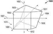
도 6A는 실시태양에 의한 형상화 연마입자 사시도이다.
도 6B는 실시태양에 의한 형상화 연마입자 사시도이다.
도 7은 실시태양에 의한 형상화 연마입자 사시도이다.
도 8은 실시태양에 의한 형상화 연마입자 사시도이다.
도 9-12는 실시태양에 의한 형상화 연마입자 부분단면도이다.
도 13은 실시태양에 의한 형상화 연마입자 사시도이다.
도 14A는 실시태양에 의한 미립자 소재 사시도이다.
도 14B 및 14C는 도 13A의 형상화 연마입자에 대한 부분 단면도이다.
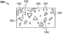
도 15-17은 실시태양에 의한 형상화 연마입자들을 도시한 것이다.
도 18은 실시태양에 의한 형상화 연마입자들을 포함한 코팅 연마재를 도시한 것이다.
도 19는 실시태양에 의한 형상화 연마입자들을 포하한 결합 연마재를 도시한 것이다.
도 20A는 실시태양에 의한 형상화 연마입자의 사시도이다.
도 20B는 실시태양에 의한 형상화 연마입자의 사시도이다.
도 21은 실시태양에 의한 형상화 연마입자의 사시도이다.
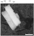
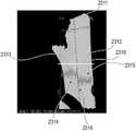
도 22는 실시태양에 의한 형상화 연마입자 사진이다.
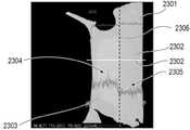
도 23A 및 23B는 실시태양에 따라 층들을 가지는 형상화 연마입자들 사진들이다.By referring to the accompanying drawings, the disclosure can be better understood, and many of its features and advantages may become apparent to those of ordinary skill in the art.
1 is a schematic view of a particulate material forming system according to an embodiment;
2 is a partial schematic view of a particulate material forming system according to an embodiment;
Fig. 3 is a state diagram after cutting according to the embodiment; Fig.
4A illustrates a particulate material forming system in accordance with an embodiment.
Figure 4B shows a portion of a system used for forming particulate material according to an embodiment.
Fig. 5 shows a part of a system used for forming a particulate material according to an embodiment.
6A is a perspective view of a shaped abrasive grain according to an embodiment.
6B is a perspective view of a shaped abrasive grain according to an embodiment.
7 is a perspective view of a shaped abrasive grain according to an embodiment.
8 is a perspective view of a shaped abrasive grain according to an embodiment.
Figures 9-12 are cross-sectional views of shaped abrasive particles according to embodiments.
13 is a perspective view of a shaped abrasive grain according to an embodiment.
14A is a perspective view of a particulate material according to an embodiment.
Figures 14B and 14C are partial cross-sectional views of the shaped abrasive particles of Figure 13A.
Figures 15-17 illustrate shaped abrasive particles according to embodiments.
Figure 18 shows a coated abrasive comprising shaped abrasive particles according to an embodiment.
Figure 19 shows a bonded abrasive article embodying shaped abrasive particles according to an embodiment.
20A is a perspective view of a shaped abrasive grain according to an embodiment.
20B is a perspective view of a shaped abrasive grain according to an embodiment.
21 is a perspective view of a shaped abrasive grain according to an embodiment.
22 is a photograph of a shaped abrasive grain according to an embodiment.
23A and 23B are photographs of shaped abrasive particles having layers according to an embodiment.
본 발명은 형상화 연마입자들 및 이러한 형상화 연마입자들의 형상들 성형방법에 관한 것이다. 형상화 연마입자들은 다양한 연마물품, 예를들면 결합 연마물품, 코팅 연마물품, 및 기타 등에 사용된다. 달리, 본원 실시태양들의 형상화 연마입자들은 자유 연마 기술 예를들면 연마 및/또는 폴리싱 슬러리에서 사용된다.The present invention relates to shaped abrasive particles and methods for shaping shapes of such shaped abrasive particles. The shaped abrasive particles are used in various abrasive articles, such as bonded abrasive articles, coated abrasive articles, and the like. Alternatively, the shaped abrasive particles of the embodiments herein are used in free abrasive techniques such as polishing and / or polishing slurries.
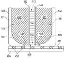
도 1은 실시태양에 의한 미립자 소재 성형에 사용되는 시스템 (100) 개략도이다. 특히, 시스템 (100)은 복합 전구체 형상화 연마입자들 성형에 사용된다. 복합 전구체 형상화 연마입자들을 성형하여 복합 형상화 연마입자들을 형성할 수 있다는 것을 이해하여야 한다.1 is a schematic diagram of a
도시된 바와 같이, 시스템 (100)은 다이 (103) 아래에서 방향 (110)으로 이동되는 벨트 (109)를 포함한다. 특정한 경우, 다이 (103)는 제1 혼합물 (101)이 담기는 제1 저장소 (171), 및 제1 저장소 (171)와 떨어져 있고 제2 혼합물 (180)이 담기는 제2 저장소 (172)를 포함한다. 상세하게는, 혼합물 (101)은 세라믹 분말소재 및 액체로 형성되는 겔일 수 있고, 겔은 미처리 (즉, 미-소성) 상태에서 주어진 형상을 유지할 수 있는 형상-안정화 소재로 특정된다. 실시태양에 의하면, 겔은 개별 입자들의 일체적 네트워크로서 세라믹 분말소재로 형성될 수 있다.As shown, the
혼합물 (101)은 특정 함량의 고형재, 예컨대 세라믹 분말소재를 포함한다. 예를들면, 일 실시태양에서, 혼합물 (101)은 혼합물 (101) 총 중량에 대하여 적어도 약 25 wt%, 예컨대 적어도 약 35 wt%, 또는 적어도 약 42 wt%의 고체 함량을 가진다. 또한, 비-제한적인 적어도 하나의 실시태양에서, 혼합물 (101)의 고체 함량은 약 75 wt% 이하, 예컨대 약 70 wt% 이하, 약 65 wt% 이하, 또는 약 55 wt% 이하이다. 혼합물 (101) 중 고체 함량은 임의의 최소 비율 및 최대 비율 사이에 있을 수 있다는 것을 이해하여야 한다The
하나의 실시태양에 따르면, 세라믹 분말소재는 산화물, 질화물, 탄화물, 붕화물, 산탄화물, 산질화물, 및 이들의 조합을 포함한다. 특정한 경우, 세라믹 재료는 알루미나를 포함한다. 더욱 상세하게는, 세라믹 재료는 알파 알루미나 전구체인 베마이트 재료를 포함한다. 용어 “베마이트”는 전형적으로 Al2O3·H2O 으로 물 함량이 15% 정도인 베마이트 광물 및, 물 함량이 15% 이상, 예컨대 20-38중량%인 유사(pseudo)베마이트 을 포함한 알루미나 수화물을 표기하도록 일반적으로 본원에서 사용된다. 베마이트 (유사베마이트 포함)는 기타 수화 알루미나들 예컨대 베마이트 미립자 소재 제조에 전구체로 통상 사용되는 ATH (삼수산화알루미늄)를 포함한 기타 알루미늄 재료와는 차별되는 특징 및 식별 가능한 결정 구조 및 따라서 특유한 X-ray 회절 패턴을 가진다는 것을 이해하여야 한다.According to one embodiment, the ceramic powder material includes oxides, nitrides, carbides, borides, oxycarbides, oxynitrides, and combinations thereof. In certain cases, the ceramic material comprises alumina. More specifically, the ceramic material comprises a boehmite material that is an alpha alumina precursor. The term " boehmite " typically refers to alumina hydrates including alumina mineral which is typically Al 2 O 3 .H 2 O and has a water content of about 15% and pseudo boehmite having a water content of at least 15%, for example 20-38 wt% As used herein. Boehmite (including pseudoboehmite) is distinguished from other aluminum materials, including ATH (aluminum trihydroxide), which is commonly used as a precursor in the production of other hydrated aluminas such as boehmite particulate material, It should be understood that it has a -ray diffraction pattern.
또한, 혼합물 (101)은 특정 함량의 액상 재료를 가진다. 일부 적합한 액체로는 유기재료, 예컨대 물을 포함한다. 하나의 실시태양에 따르면, 혼합물 (101)은 혼합물 (101) 중 고체 함량보다 낮은 액체 함량을 가지도록 형성된다. 특정 실시예들에서, 혼합물 (101)의 액체 함량은 혼합물 (101) 총 중량에 대하여 적어도 약 25 wt%이다. 다른 실시예들에서, 혼합물 (101)의 액체 함량은 더 크고, 예컨대 적어도 약 35 wt%, 적어도 약 45 wt%, 적어도 약 50 wt%, 또는 적어도 약 58 wt%이다. 또한, 비-제한적인 적어도 하나의 실시태양에서, 혼합물의 액체 함량은 약 75 wt% 이하, 예컨대 약 70 wt% 이하, 약 65 wt% 이하, 약 60 wt% 이하, 또는 약 65 wt% 이하이다. 혼합물 (101) 중 액체 함량은 상기 임의의 최소 비율 및 최대 비율 사이에 있을 수 있다는 것을 이해하여야 한다.Also, the
또한, 본원 실시태양에 의한 형상화 연마입자들 처리 및 성형이 용이하도록, 혼합물 (101)은 특정 저장탄성률을 가진다. 예를들면, 혼합물 (101)의 저장탄성률은 적어도 약 1x10⁴ Pa, 예컨대 적어도 약 4x10⁴ Pa, 또는 적어도 약 5x10⁴ Pa이다. 그러나, 비-제한적인 적어도 하나의 실시태양에서, 혼합물 (101)의 저장탄성률은 약 1x10⁷ Pa 이하, 예컨대 약 1x10⁶ Pa 이하이다. 혼합물 (101)의 저장탄성률은 상기 임의의 최소값 및 최대값 사이의 범위일 수 있다는 것을 이해하여야 한다. 저장탄성률은 ARES 또는 AR-G2 회전형 레오미터를 이용한 평행판 시스템 및 펠티어 판 (Peltier plate) 온도 조절시스템으로 측정한다. 시험에 있어서, 혼합물 (101)을 서로 대략 8 mm 이격 설정되는 두 판들 사이 간극으로 압출한다. 간극으로 압축한 후, 혼합물 (101)이 완전히 판들 사이 간극을 채울 때까지 간극을 형성하는 두 판들 사이 간격을 2 mm로 좁힌다. 과잉 혼합물을 닦아낸 후, 간격을 0.1 mm만큼 좁히고 시험을 개시한다. 시험은 변형 범위가 0.1% 내지 100%, 6.28 rad/s (1 Hz)로 설정된 장비로, 25-mm 평행판을 이용하고 10 포인트 감소할 때 기록하는 진동 변형 일소 시험이다. 시험 완료 후 1 시간 내에, 간격을 다시 0.1 mm만큼 좁히고 시험을 반복한다. 시험은 적어도 6 회 반복한다. 제1 시험은 제2 및 제3 시험들과는 다를 수 있다. 각각의 시편에 대한 제2 및 제3 시험들 결과만을 보고하여야 한다. 점도는 저장탄성률 값을 6.28 s-1로 나누어 계산할 수 있다.Further, the
또한, 본원 실시태양에 의한 형상화 연마입자들 처리 및 성형이 용이하도록, 혼합물 (101)은 특정 점도를 가진다. 예를들면, 혼합물 (101)의 점도는 적어도 약 4x10³ Pa s, 적어도 약 5x10³ Pa s, 적어도 약 6x10³ Pa s, 적어도 약 8x10³ Pa s, 적어도 약 10x103 Pa s, 적어도 약 20x103 Pa s, 적어도 약 30x103 Pa s, 적어도 약 40x103 Pa s, 적어도 약 50x103 Pa s, 적어도 약 60x103 Pa s, 또는 적어도 약 65x103 Pa s이다. 비-제한적인 적어도 하나의 실시태양에서, 혼합물 (101)의 점도는 약 1x10⁶ Pa s 이하, 약 5x10⁵ Pa s 이하, 약 3x10⁵ Pa s 이하, 또는 약 2x10⁵Pa s 이하이다. 혼합물 (101) 점도는 상기 임의의 최소값 및 최대값 사이의 범위일 수 있다는 것을 이해하여야 한다.Further, to facilitate processing and shaping of shaped abrasive particles according to embodiments of the present invention, the
또한, 본원 실시태양에 의한 형상화 연마입자들 처리 및 성형이 용이하도록, 혼합물 (101)은 상기 액체와는 구별되는 유기 첨가제들을 포함한 특정 함량의 유기재료들을 가지도록 형성된다. 일부 적합한 유기 첨가제들은 안정화제, 바인더, 예컨대 프룩토오스, 수크로오스, 락토오스, 글루코오스, UV 경화성 수지들, 및 기타 등을 포함한다.Further, to facilitate processing and shaping of shaped abrasive particles according to embodiments of the present invention, the
특히, 본원 실시태양들은 종래 테이프 주조 공정에서 사용되는 슬러리와 차별되는 혼합물 (101)을 사용한다. 예를들면, 혼합물 (101) 내의 유기재료들, 특히, 임의의 상기 유기 첨가제들의 함량은 혼합물 (101) 내의 다른 성분들과 비교할 때 소량이다. 적어도 하나의 실시태양에서, 혼합물 (101)은 혼합물 (101) 총 중량에 대하여 약 30 wt% 이하의 유기재료를 가지도록 형성된다. 다른 실시예들에서, 유기재료 함량은 더 적고, 예컨대 약 15 wt% 이하, 약 10 wt% 이하, 또는 약 5 wt% 이하이다. 또한, 비-제한적인 적어도 하나의 실시태양에서, 혼합물 (101) 내의 유기재료 함량은 혼합물 (101) 총 중량에 대하여 적어도 약 0.5 wt%이다. 혼합물 (101) 내의 유기재료 함량은 상기 임의의 최소값 및 최대값 사이의 범위일 수 있다는 것을 이해하여야 한다.In particular, the embodiments herein use a
또한, 본원 실시태양에 의한 형상화 연마입자들 처리 및 성형이 용이하도록 혼합물 (101)은 상기 액체와는 구분되는 특정 함량의 산 또는 염기를 가지도록 형성된다. 일부 적합한 산 또는 염기는 질산, 황산, 시트르산, 염소산, 타타르산, 인산, 질산암모늄, 구연산암모늄을 포함한다. 특정 실시태양에 의하면, 질산 첨가제를 사용하여 혼합물 (101)은 약 5 미만, 더욱 상세하게는, 약 2 내지 약 4 pH를 가진다.In addition, the
특히, 제2 혼합물 (180)은 제1 혼합물 (101)과 임의의 동일한 특성들, 예를들면, 저장탄성률, 고형재 함량, 액상 재료 함량, 및 유기재료 함량을 가지는 겔일 수 있다. 또한, 특정한 경우, 제2 혼합물 (180)은 제1 혼합물 (101)과는 상이한 적어도 하나의 특징부를 가질 수 있다. 특정한 경우, 제1 혼합물 (101) 및 제2 혼합물 (180)은 상이한 조성을 가지고, 두 혼합물들 간 적어도 하나의 원소가 상이하다. 예를들면, 제1 혼합물 (101)은 제2 혼합물 (180)에 존재하지 않는 도펀트 재료를 가진다. 달리, 제2 혼합물 (180)은 제1 혼합물 (101)에 부재한 도펀트 재료를 가진다.In particular, the second mixture 180 may be a gel having any of the same properties as the
또 다른 실시태양에서, 제1 혼합물 (101)은 혼합물 성분들에 있어서 제2 혼합물 (180)과 상이할 수 있다. 예를들면, 혼합물들 중 하나는 다른 혼합물의 상기 첨가제와는 상이한 함량의 첨가제, 예컨대 바인더, 공극형성제, 섬유재, 및 기타 등을 가질 수 있다. 다른 실시태양에서, 제1 혼합물 (101)은 제2 혼합물 (180)과 대비하여 상이한 함량의 고형재, 예컨대 세라믹 분말소재를 가진다. 기타 실시태양들에서, 제1 혼합물 (101)은 제2 혼합물 (180)의 액상 재료 함량과 비교하여 상이한 함량의 액상 재료를 함유한다. 또한, 제2 혼합물 (180)과 비교하여 제1 혼합물 (101)은 상이한 특성들, 예컨대 저장탄성률을 가진다.In yet another embodiment, the
도시된 바와 같이, 제1 혼합물 (101)이 저장소 (172)와 분리된 저장소 (171)에 담기도록 다이 (103)가 형성된다. 제1 혼합물 (101)은 방향 (191)으로 다이 개구 (105)를 통과하여 다이 개구 (105) 아래에 있는 벨트 (109)로 압출된다. 실제로, 제1 혼합물 (101)은 다이 개구 (105)를 통하여 다이 (103)에서 유출되어 벨트 (109)에 직접 압출된다. 따라서, 특정한 경우, 시스템 (100)은 제1 혼합물 (101)이 벨트 (109)에 압출되어 벨트 (109)를 따라 방향 (110)로 병진하는 제1 형태를 형성하도록 사용된다.As shown, a
실시태양에 의하면, 다이 개구 (105)는 직사각형을 가진다. 또한, 다이 개구 (105)를 통해 압출되는 혼합물 (101)은 다이 개구 (105)와 실질적으로 동일한 단면 형상을 가진다. 따라서, 소정의 실시태양들에서, 혼합물 (101)이 성형체로서 압출된다. 본원에서 성형체는 포괄적으로 임의의 형상화 세라믹 몸체를 언급한다. 성형체는 원하는 형상 및 성형방법에 따라 다양한 형상들 및 외곽선들을 가진다. 도시된 실시태양에서, 본 공정은 시트 (111) 형상을 가지는 성형체 압출 단계를 포함한다. 시트 (111)는 시트 (111)의 두께 (t) 및 폭 (w)로 정의되는 평면에서 관찰할 때 대략 직사각 단면 형상을 가진다.According to an embodiment, the
제1 재료 (101)는 다이 개구 (105)를 통해 혼합물 (101)을 압출하기 위하여 혼합물 (101)에 힘 (190) (또는 압력)을 인가하여 압출된다. 실시태양에 의하면, 압출 과정에서 특정 압력이 활용될 수 있다. 예를들면, 압력은 적어도 약 10 kPa, 예컨대 적어도 약 500 kPa이다. 또한, 비-제한적인 적어도 하나의 실시태양에서, 압출 과정에서 적용되는 압력은 약 4 MPa 이하이다. 혼합물 (101) 압출에 적용되는 압력은 상기 임의의 최소값 및 최대값 사이의 범위일 수 있다는 것을 이해하여야 한다The
도시된 바와 같이, 시스템 (100)은 다이 개구 (173)를 통해 방향 (175)으로 저장소 (172)로부터 제2 재료 (180)를 압출한다. 특히, 다이 개구 (173)는 다이 개구 (105)로부터 이격되고 구분된다. 방향 (175)으로 압력이 인가되면 제2 저장소 (172)로부터 제2 재료 (180)가 압출된다는 것을 이해할 수 있다. 소정의 실시예들에서, 제2 혼합물 (180)을 압출하기 위한 힘은 제1 재료 (101)를 저장소 (171)에서 압출하기 위한 힘과 실질적으로 동일하다. 또한, 다른 실시예들에서, 저장소 (172)에서 제2 혼합물 (180)을 압출하기 위한 힘은 제1 재료 (101)를 저장소 (171)에서 압출하기 위한 힘과 상이하다.As shown, the
실시태양에 의하면, 공정을 통해 복합 시트 (111)가 성형되고, 상기 시스템 (100)은 제1 시트 (181)를 형성하고 제1 시트 (181)에 적층되는 제2 시트 (182)를 형성한다. 소정의 실시예들에서, 제1 시트 (181)는 제2 시트 (182) 아래에 놓이고, 더욱 상세하게는, 제1 시트 (181)는 제2 시트 (182)와 직접 접촉한다. 또한, 복합 시트 (111) 제1 시트 (181) 및 제2 시트 (182)로부터 형성되는 것으로 도시되지만, 추가 혼합물들 또는 재료는 복합 시트 (111)에 추가적인 부분들 또는 층들을 형성할 수 있다.According to an embodiment, a
특정한 경우, 시스템 (100)은 공-압출 프로세서로 진행되며, 제1 혼합물 (101) 및 제2 혼합물 (180)은 동시에 병진 벨트 (109)에 압출되어 복합 시트 (111)를 형성한다. 또한, 시스템 (100)은 제1 다이 개구 (105) 및 제2 다이 개구 (173) 간의 특정 배열로 도시되지만, 대안적 다이 배열들이 적용될 수 있다. 예를들면, 다른 실시태양들에서 다이 개구들 (105, 173)은 서로 동축 관계에 있을 수 있다. 기타 실시태양들에서, 다이 개구들 (105, 173)은 측방 인접 배향으로 배열되어, 다이 개구들은 시트 (111) 폭만큼 나란히 배열될 수 있다. 또한, 시스템 (100)은 각각의 다이 개구가 구분되고 이격 상태로 연관되는 상이한 다이들을 사용할 수 있다.In certain instances, the
또한, 시스템 (100)은 2개의 다이 개구들 (105, 173)을 포함하는 다이 (103)를 도시하지만, 기타 다이들은 추가 저장소들과 연관되는 추가 다이 개구들을 포함할 수 있다. 예를들면, 다이 (103)는 제3 혼합물을 담을 수 있는 제3 저장소를 가진다. 제3 혼합물은 제1 혼합물 (101) 또는 제2 혼합물 (171)과 비교하여 상이할 수 있다. 또한, 제3 혼합물은 제1 및 제2 혼합물과 공-압출되어 제1 혼합물 (101), 제2 혼합물 (171), 및 제3 혼합물을 포함하는 복합 압출물을 형성한다.
일부 실시태양들에서, 혼합물 (101)이 다이 개구 (105)에서 압출되면서 동시에 벨트 (109)는 병진된다. 시스템 (100)에 도시된 바와 같이, 혼합물 (101)은 방향 (191)으로 압출된다. 벨트 (109)의 병진 방향 (110)은 혼합물 압출 방향 (191)에 대하여 각을 형성한다. 시스템 (100)에서 병진 방향 (110) 및 압출 방향 (191) 사이 각이 실질적으로 직교하는 것으로 도시되지만, 기타 각들 예를들면, 예각 또는 둔각이 고려될 수 있다. 또한, 혼합물 (101)이 벨트 (109) 병진 방향 (110)에 대하여 유각의 방향 (191)으로 압출되는 것으로 도시되지만, 대안적 실시태양에서, 벨트 (109) 및 혼합물은 (101) 실질적으로 동일한 방향으로 압출될 수 있다.In some embodiments, the
벨트 (109)는 처리가 용이하도록 특정 속도로 병진된다. 예를들면, 벨트 (109)는 적어도 약 3 cm/s로 병진한다. 다른 실시태양들에서, 벨트 (109) 병진 속도는 더 빠를 수 있고, 예컨대 적어도 약 4 cm/s, 적어도 약 6 cm/s, 적어도 약 8 cm/s, 또는 적어도 약 10 cm/s이다. 또한, 비-제한적인 적어도 하나의 실시태양에서, 벨트 (109)는 약 5 m/s 이하, 약 1 m/s 이하, 또는 약 0.5 m/s 이하로 방향 (110)으로 전진한다. 스크린 (151)은 상기 임의의 최소값 및 최대값 사이의 범위의 속도로 병진할 수 있다는 것을 이해하여야 한다.The
본원 실시태양에 의한 소정의 프로세스에 있어서, 방향 (191)의 혼합물 (101) 압출 속도에 대하여 벨트 (109) 병진 속도가 조절되어 적절한 처리를 가능하게 한다. 예를들면, 벨트 (109) 병진 속도는 압출 속도와 실질적으로 동일하여 적합한 시트 (111) 형성이 보장된다.In certain processes according to embodiments of the present invention, the velocity of translation of the
혼합물 (101)이 다이 개구 (105)를 통과하여 압출된 후, 혼합물 (101)은 다이 (103) 표면에 부착된 칼날 (107) 아래로 벨트 (109)를 따라 전진된다. 칼날 (107)은 시트 (111) 형성을 가능하게 한다. 시트 (111)는 특정 치수, 예를들면 길이 (l), 폭 (w), 및 두께 (t)를 가진다. 실시태양에 의하면, 시트 (111)는 병진 벨트 (109) 방향으로 연장되는 길이를 가지고, 이는 폭보다 더 크고, 시트 (111) 폭은 벨트 (109) 길이 및 시트 길이에 수직 방향으로 연장되는 치수이다. 시트 (111)는 두께 (184)를 가지고, 길이 및 폭은 시트 (111) 두께 (184)보다 크다. 하나의 실시태양에 따르면, 시트 (111)는 길이 (l), 폭 (w), 및 높이 (h)를 가지고, 이때 길이> 폭> 높이이다. 또한, 시트 (111)의 길이: 높이의2차 종횡비는 적어도 약 10, 예컨대 적어도 약 100, 적어도 약 1000, 또는 적어도 약 1000이다.After the
특히, 시트 (111) 두께 (184)는 벨트 (109) 표면에서 수직 연장되는 치수이다. 실시태양에 의하면, 시트 (111)는 특정 치수의 두께 (184)를 가지도록 형성되고, 두께는 시트 (111)의 다중 측정치들의 평균 두께다. 예를들면, 시트 (111) 두께 (184)는 적어도 약 0.1 mm, 예컨대 적어도 약 0.5 mm이다. 다른 실시예들에서, 시트 (111) 두께 (184)는 더 높고, 예컨대 적어도 약 0.8 mm, 적어도 약 1 mm, 적어도 약 1.2 mm, 적어도 약 1.6 mm, 또는 적어도 약 2 mm이다. 또한, 비-제한적 일 실시태양에서, 시트 (111) 두께 (184)는 약 10 mm 이하, 약 5 mm 이하, 또는 약 2 mm 이하이다. 시트 (111)는 상기 임의의 최소값 및 최대값 사이의 범위의 평균 두께를 가질 수 있다는 것을 이해하여야 한다.In particular, the thickness of the
다이 (103)로부터 혼합물 (101)을 압출한 후, 시트 (111)는 벨트 (109) 표면을 따라 방향 (112)으로 전진한다. 벨트 (109)를 따라 시트 (111)를 병진시키면 전구체 형상화 연마입자들 형성 공정이 더욱 용이하다. 예를들면, 시트 (111)는 형상화 구역 (113)에서 형상화 공정이 수행된다. 특정한 경우, 형상화 공정은 시트 (111) 표면, 예를들면, 시트 (111) 상부 주면 (117)에 대한 형상화를 포함한다. 다른 실시태양들에서, 기타 시트 주면들에 대한 예를들면, 저면 또는 측면들에 대한 형상화를 포함할 수 있다. 소정의 프로세스에 있어서, 형상화는 하나 이상의 공정들, 예컨대, 엠보싱, 압연, 절단, 조각, 패턴화, 신장, 비틀림, 및 이들의 조합을 통해 시트의 외곽선 (contour)을 변경시키는 것을 포함한다.After extruding the
하나의 특정 실시태양에서, 형상화 공정은 시트 (111)의 상부 주면 (117)의 형상 (119)을 성형하는 것을 포함한다. 상세하게는, 형상화 구조체 (115)는 시트 (111) 상부 주면 (117)과 접촉하여 형상 (119) 또는 형상들 패턴을 상부 주면 (117)에 형성시킨다. 형상화 구조체 (115)는 다양한 형태를 취할 수 있고, 예를들면, 표면에 다양한 형상들을 가지는 롤러를 포함하고, 형상화 구조체 (115) 및 상부 주면 (117) 간의 접촉 시에 이러한 형상들이 시트 (111) 상부 주면 (117)으로 전달된다.In one particular embodiment, the shaping process includes shaping the
또한, 대안적 형상화 구조체들 및 시트 형상화 방법들이 적용될 수 있다는 것을 이해하여야 한다. 예를들면, 벨트 (109) 표면이 표면 처리되고 표면 처리된 형상들이 시트 (111), 및 최종-성형 형상화 연마입자들에 부여될 수 있다. 또한, 다양한 장치들이 사용되어 형상 또는 형상들 패턴이 시트 (111) 측면들에 부여될 수 있다.It should also be appreciated that alternative shaping structures and sheet shaping methods can be applied. For example, the surfaces of the
실시태양에 의하면, 형상화 연마입자 형성 공정은 벨트 (109)를 따라 시트 (111)가 형성 구역 (121)을 통과하도록 전진하는 것을 더욱 포함한다. 실시태양에 의하면, 형상화 연마입자 형성 공정은 시트 (111)를 절단하여 전구체 형상화 연마입자들 (123)을 형성하는 것을 포함한다. 예를들면, 소정의 실시예들에서, 형성 공정은 시트 (111) 일부에 대한 천공화를 더욱 포함한다. 다른 실시예들에서, 형성 공정은 시트 (111) 패턴화에 의한 패턴화 시트 형성 및 패턴화 시트로부터 형상들의 추출을 포함한다.According to an embodiment, the shaping abrasive grain forming process further comprises advancing the
특정 형성 공정은 절단, 압축, 천공, 분쇄, 압연, 비틀림, 굽힘, 건조, 및 이들의 조합을 포함한다. 일 실시태양에서, 형성공정은 시트 (111) 절단을 포함한다. 시트 (111) 절단은 기체, 액체, 또는 고체 형태일 수 있는 적어도 하나의 기계체를 사용한다. 절단공정은 절단, 압축, 천공, 분쇄, 압연, 비틀림, 굽힘, 및 건조의 적어도 하나의 또는 조합을 포함한다. 또한, 절단은 시트 (111) 일부에 대한 시트 (111) 높이 전체를 연장하지 않는 천공화 또는 부분 개구 생성을 포함한다는 것을 이해하여야 한다. 예를들면, 절단은 물 분사 절단 프로세스를 포함할 수 있다. 다른 실시태양에서, 시트 (111) 절단은 하나 또는 다수의 블레이드, 와이어, 디스크, 및 이들의 조합을 포함한 기계체의 사용을 포함한다. 블레이드들은 서로에 대하여 다양한 구성으로 배향되어 바람직한 절단을 달성한다. 예를들면, 갱 구조와 같이 블레이드들은 서로 평행하게 배열된다. 달리, 기계체는 서로 연결되거나 서로 독립적으로 일조의 나선형 블레이드들을 포함한다.The particular forming process includes cutting, compressing, punching, grinding, rolling, twisting, bending, drying, and combinations thereof. In one embodiment, the forming process includes
달리, 형상화 연마입자들 형성공정은 시트 (111)를 개별 전구체 형상화 연마입자들로 절단하기 위하여 복사선을 이용한다. 예를들면, 복사선 이용은 시트 (111)로부터 개별 형상화 연마입자들을 새기거나 달리 절단하는 레이저 이용을 포함한다.Alternatively, the process of forming shaped abrasive particles uses radiation to cut the
적어도 하나의 블레이드가 시트 (111)를 통과하여 이동되면서 절단할 수 있다는 것을 이해하여야 한다. 특정한 경우 블레이드를 이용한 절단공정에서 제1 방향, 및 제1 방향과 다른 제2 방향을 포함하여 다중 방향들로 블레이드가 시트 (111)를 통과하도록 이동한다. 상세하게는, 소정의 절단공정에서 다수의 블레이드들은 다중 방향들로 시트 (111)를 가로지르고 통과하도록 이동되어 전구체 형상화 연마입자들 (123)을 형성한다.It should be understood that at least one blade can be cut while moving through the
소정의 실시예들에서, 절단 방법은 시트 (111)에 형성된 개구 또는 천공을 유지하는 것을 포함한다. 시트 (111) 절단이 기계체에 의해 이루어진 후 개구 (415)가 유지되면 형상화 연마입자들 및 형상화 연마입자들의 형상들 및 형상화 연마입자들 배치의 형상들 형성에 적합하다. 개구 유지는 개구를 형성하는 시트 (111)의 적어도 하나의 표면을 적어도 부분 건조하는 것을 포함한다. 적어도 부분 건조 공정은 개구에 건조물질을 지향하는 것을 포함한다. 건조물질은 액체, 고체, 또는 심지어는 기체를 포함한다. 또한, 개구 유지 공정은 건조물질, 예컨대 기체를, 개구에 선택적으로 지향하고 개구 (415)와 실질적으로 이격되는 기타 시트 (111) 표면들에 기체 충돌을 제한하는 것을 포함한다.In some embodiments, the cutting method includes maintaining an opening or perforation formed in the
소정의 실시예들에서, 절단공정은 시트가 충분히 건조되기 전에 수행된다. 예를들면, 절단은 시트 (111) 초기 형성 과정에서의 원래 액체 함량과 대비하여 시트 (111)에서 약 20% 이하의 액체가 휘발 되기 전에 수행된다. 다른 실시태양들에서, 절단 전 후 허용 가능한 휘발 함량은 더 적고, 예컨대, 시트 원래 액체 함량의 약 15% 이하, 약 12% 이하, 약 10% 이하, 약 8% 이하, 또는 약 4% 이하이다.In certain embodiments, the cutting process is performed before the sheet is sufficiently dried. For example, the cutting is performed before about 20% or less of the liquid in the
본원의 실시태양에서 기재된 바와 같이, 절단공정은 형성공정과 동시에 수행된다. 또한, 절단공정은 형성공정에 연속하여 수행된다. 휘발에 따라 달라지는 융제 공정의 경우와 같이 절단공정은 반드시 시트 조성의 변경을 포함할 필요는 없다.As described in the embodiments herein, the cutting process is performed simultaneously with the forming process. Further, the cutting step is performed continuously in the forming step. As in the case of the fluxing process which depends on volatilization, the cutting process need not necessarily involve alteration of the sheet composition.
하나의 실시태양에 따르면, 절단공정은 형성공정을 유리하게 하는 특정 조건들에서 수행된다. 예를들면, 절단공정은 제어된 습도, 제어된 온도, 제어된 기압, 제어된 기류, 제어된 분위기 기체 조성, 및 이들의 조합 중 적어도 하나를 포함하는 제어된 절단 조건들에서 수행된다. 이러한 조건들을 제어함으로써 시트 건조 및 특정 형상들을 가지는 형상화 연마입자들 형성을 용이하게 한다. 특정 실시태양에 의하면, 절단공정은 제한적이지 않지만 습도, 온도, 기압, 기류, 분위기 기체 조성, 및 이들의 조합을 포함하는 하나 이상의 소정의 분위기 조건들의 감시 및 조절을 포함한다.According to one embodiment, the cutting process is performed under certain conditions that favor the forming process. For example, the cutting process is performed under controlled cutting conditions comprising at least one of controlled humidity, controlled temperature, controlled air pressure, controlled airflow, controlled atmosphere gas composition, and combinations thereof. These conditions are controlled to facilitate sheet drying and shaping abrasive particles having certain shapes. According to certain embodiments, the cutting process includes, but is not limited to, monitoring and conditioning of one or more predetermined atmospheric conditions, including humidity, temperature, air pressure, airflow, atmospheric gas composition, and combinations thereof.
적어도 하나의 실시태양에 있어서, 절단공정에 적용되는 분위기 온도 (즉, 절단 온도)는 기타 공정에 적용되는 분위기 온도와 관련하여 조절될 수 있다. 예를들면, 절단 온도는 시트 형성 과정 (예를들면, 압출)에 적용되는 온도와 실질적으로 상이한 온도에서 수행된다. 달리, 시트 형성과정에서 적용되는 온도는 절단 온도와 실질적으로 동일할 수 있다. 또한, 다른 실시태양에서, 기계체는 절단 과정 중에서 시트 (111) 온도보다 더욱 고온일 수 있다. 대안적 조건에서, 기계체는 시트 (111) 온도 미만일 수 있다.In at least one embodiment, the ambient temperature (i.e., the cutting temperature) applied to the cutting process may be adjusted in relation to the ambient temperature applied to the other process. For example, the cutting temperature is performed at a temperature that is substantially different from the temperature applied to the sheet forming process (e.g., extrusion). Alternatively, the temperature applied in the sheet forming process may be substantially equal to the cutting temperature. Further, in other embodiments, the machine body may be hotter than the
또 다른 양태에서, 절단공정은 절단 후 시트 (111)에 형성된 개구에 절단 후 시트에 있는 개구를 충분히 유지할 수 있는 적어도 하나의 개구 조제를 제공하는 것을 포함한다. 일부 적합한 개구 조제 제공방법은 적층, 도포, 분사, 인쇄, 압연, 전달, 및 이들의 조합을 포함한다. 하나의 특정 실시태양에서, 기계체는 적어도 하나의 개구 조제로 코팅되고, 개구 조제는 기계체 표면에서 개구를 형성하는 시트 표면으로 전달된다. 개구 조제는 무기재료, 유기재료, 고분자, 및 이들의 조합으로 이루어진 군에서 선택되는 재료를 포함한다. 일 실시태양에서, 개구 조제는 발포제, 계면활성제, 및 이들의 조합일 수 있다.In another embodiment, the cutting process includes providing at least one opening preparation that is capable of sufficiently retaining the openings in the sheet after cutting to openings formed in the
도 2는 형성 구역 (121)에서 절단에 사용되는 특정 장치를 도시한 것이다. 도시된 바와 같이, 절단공정은 서로 평행한 다수의 블레이드들 (202, 203, 204, 205, 206)을 가지는 절단 장치 (201)를 이용한다. 절단 장치 (201)는 다중 방향들로 시트 (111)를 통과하여 전구체 형상화 연마입자들 (123)을 형성한다. 예를들면, 도 2에 도시된 바와 같이, 먼저 절단 장치 (201)는 시트 (111) 길이 (l)에 대하여 유각인 방향 (207)로 병진된다. 이후, 절단 장치 (201)는 제1 방향 (207)과 다르고 제1 방향 (207)에 대하여 유각인 제2 방향 (209)으로 병진된다. 마지막으로, 절단 장치 (201)는 제1 방향 (207) 또는 제2 방향 (209)과 상이한 제3 방향 (208)으로 시트 (111)를 가로질러 통과하여 전구체 형상화 연마입자들을 형성한다. 단일 절단 장치 (201)가 다중 방향들로 이동하는 것으로 기재되지만, 개별 및 별개 절단 방향들에 대하여 별개 절단 장치들이 적용될 수 있다는 것을 이해하여야 한다.Fig. 2 shows a specific apparatus used for cutting in the forming
절단공정은 단일 절단공정으로 상이한 유형의 형상화 연마입자들을 생성한다. 상이한 유형의 형상화 연마입자들은 본원 실시태양들의 동일한 프로세스들로 형성된다. 상이한 유형의 형상화 연마입자들은 제1의 2차원 형상을 가지는 제1 유형의 형상화 연마입자 및 상이한2차원 형상을 가지는 제2 유형의 형상화 연마입자를 포함한다. 또한, 상이한 유형의 형상화 연마입자들은 서로 크기가 다르다. 예를들면, 상이한 유형의 형상화 연마입자들은 서로 상이한 부피를 가진다. 상이한 유형의 형상화 연마입자들을 형성할 수 있는 단일 공정은 소정의 유형의 연마물품을 생산하는데 특히 적합하다The cutting process produces different types of shaped abrasive particles in a single cutting process. Different types of shaped abrasive particles are formed with the same processes of the embodiments of the present invention. The different types of shaped abrasive particles comprise a first type of shaped abrasive grain having a first two-dimensional shape and a second type of shaped abrasive grain having a different two-dimensional shape. Furthermore, different types of shaped abrasive particles differ in size from one another. For example, different types of shaped abrasive particles have different volumes from each other. A single process capable of forming different types of shaped abrasive particles is particularly suitable for producing a given type of abrasive article
도시된 바와 같이, 절단 장치 (201)로 시트 (111)를 절단하면, 시트 (111)에서 다수의 전구체 형상화 연마입자들이 형성된다. 특정한 경우, 도 2에 도시된 바와 같이, 제1 유형의 전구체 형상화 연마입자들 (240)이 시트 (111)에서 형성된다. 전구체 형상화 연마입자들 (240)은 시트 (111)의 길이 (l) 및 폭 (w)으로 정의되는 평면에서 관찰할 때 대략 삼각형의 2차원 형상을 가진다.As shown, cutting the
또한, 절단공정은 시트 (111) 가장자리에 및 근접한 다른 유형의 전구체 형상화 연마입자들 (243)을 형성한다. 전구체 형상화 연마입자들 (243)은 시트 (111)의 길이 (l) 및 폭 (w)에 의해 정의되는 평면에서 관찰할 때 2차원 삼각형을 가진다. 그러나, 전구체 형상화 연마입자들 (243)은 전구체 형상화 연마입자들 (240)보다 크기가 더 작다. 특정한 경우, 전구체 형상화 연마입자들 (243)은 전구체 형상화 연마입자들 (240) 부피의 약 95% 이하의 부피를 가진다. 부피는 동일한 유형의 적어도 20개의 형상화 연마입자들의 부피 측정 계산의 평균치이다. 다른 실시예들에서, 전구체 형상화 연마입자들 (243)은 전구체 형상화 연마입자들 (240) 부피의 약 92% 이하, 약 90% 이하, 약 85% 이하, 예컨대 약 80% 이하, 약 75% 이하, 약 60% 이하, 또는 약 50% 이하의 부피를 가진다. 또한, 비-제한적 일 실시태양에서, 전구체 형상화 연마입자들 (243)의 부피는 전구체 형상화 연마입자들 (240) 부피의 적어도 약 10%, 예컨대 적어도 약 20%, 적어도 약 30%, 또는 적어도 약 40% 이다. 전구체 형상화 연마입자들 (243) 및 전구체 형상화 연마입자들 (240) 간의 부피 차이는 상기 임의의 최소 비율 및 최대 비율 사이에 있을 수 있다는 것을 이해하여야 한다.In addition, the cutting process forms other types of precursor shaping
시트 (111)로부터 전구체 형상화 연마입자들 (240, 243)을 형성하기 위하여 사용되는 동일한 절단공정에서 다른 유형의 전구체 형상화 연마입자들 (242)이 형성된다. 특히, 전구체 형상화 연마입자들 (242)은 시트 (111)의 폭 (w) 및 길이 (l)에 의해 정의되는 평면에서 관찰할 때 2차원 사각 형상을 가진다. 특정 실시태양에 의하면, 전구체 형상화 연마입자들 (242)은 평행사변형의2차원 형상을 가진다. 전구체 형상화 연마입자들 (242)은 본원 기타 실시태양들에 기재된 기타 전구체 형상화 연마입자들과 비교하여 상이한 부피를 가질 수 있다는 것을 이해하여야 한다.Other types of precursor shaping
절단공정은 동일한 시트 (111)에서 전구체 형상화 연마입자들 (240, 242, 243)와는 다른 유형의 형상화 연마입자 (244)를 형성한다. 특히, 전구체 형상화 연마입자들 (244)은 전구체 형상화 연마입자들 (240, 242, 243)와 비교하여 상이한2차원 다각형을 가진다. 도 2의 실시태양에 도시된 바와 같이, 전구체 형상화 연마입자들 (244)은 사각 형상, 더욱 상세하게는, 시트 (111)의 폭 (w) 및 길이 (l)에 의해 정의되는 평면에서 관찰할 때 사다리꼴 형상을 가진다. 전구체 형상화 연마입자들 (244)은 본원 기타 실시태양들에 기재된 기타 전구체 형상화 연마입자들과 비교하여 상이한 부피를 가질 수 있다는 것을 이해하여야 한다.The cutting process forms shaped
도 3은 실시태양에 의한 절단공정 후의 시트 (111)일부를 도시한 것이다. 특히, 시트 (111)는 제1 방향 (308)으로 절단되고, 연속하여 제1 방향 (308)에 대하여 유각인 제2 방향 (307)으로 절단된다. 절단공정은 시트 (111)의 길이 및 폭에 의해 정의되는 평면에서 관찰할 때 대략 사각형의 전구체 형상화 연마입자들 (321)을 생성한다. 또한, 절단공정에 따라, 전구체 형상화 연마입자들 (321) 생성에 사용되는 동일한 절단공정에서 상이한 유형의 전구체 형상화 연마입자들 (322)이 생성된다. 특히, 전구체 형상화 연마입자들 (322)은 전구체 형상화 연마입자들 (321)과 비교하여 2차원 형상, 크기, 및 이들의 조합에 있어서 상이하다. 예를들면, 전구체 형상화 연마입자들 (322)은 전구체 형상화 연마입자들 (321)과 비교할 때 더 큰 부피를 가진다.Fig. 3 shows a part of the
다시 도 1을 참고하면, 전구체 형상화 연마입자들 (123) 형성 후, 입자들은 후-성형 구역 (125)을 통과한다. 예를들면, 가열, 경화, 진동, 함침, 도핑, 및 이들의 조합을 포함한 다양한 공정들이 후-성형 구역 (125)에서 수행될 수 있다.Referring again to FIG. 1, after forming the precursor shaping
일 실시태양에서, 후-성형 구역 (125)은 가열 공정을 포함하고, 전구체 형상화 연마입자들 (123)은 건조된다. 건조공정은 휘발성 물질, 예컨대 물을 포함한 특정 함량의 물질을 제거한다. 실시태양에 의하면, 건조공정은 약 300℃ 이하, 예컨대 약 280℃ 이하 또는 약 250℃ 이하의 건조 온도에서 수행된다. 또한, 비-제한적 일 실시태양에서, 건조공정은 적어도 약 50℃의 건조 온도에서 수행된다. 건조 온도는 상기 임의의 최소온도 및 최대온도들 사이의 범위에 있을 수 있다는 것을 이해하여야 한다.In one embodiment, the
또한, 전구체 형상화 연마입자들 (123)은 후-성형 구역을 특정 속도, 예컨대 적어도 약 0.2 feet/min 및 약 8 feet/min 이하로 통과한다.Also, the precursor shaping
또한, 건조공정은 특정 주기 동안 수행된다. 예를들면, 건조공정은 약6 시간 이하로 진행된다.Further, the drying process is performed for a specific period. For example, the drying process proceeds to about 6 hours or less.
전구체 형상화 연마입자들 (123)이 후-성형 구역 (125)을 통과한 후, 입자들은 벨트 (109)에서 제거된다. 추가 공정을 위하여 전구체 형상화 연마입자들 (123)은 통 (127)에 회수된다.After the precursor shaping
실시태양에 의하면, 형성공정 형상화 연마입자들은 소결 공정을 더욱 포함한다. 소정의 공정들에서, 소결 공정은 벨트 (109)에서 전구체 형상화 연마입자들 (123)을 회수한 후 진행된다. 달리, 소결 공정은 전구체 형상화 연마입자들 (123)이 벨트에 있는 동안 진행된다. 전구체 형상화 연마입자들 (123)을 소결함으로써 일반적으로 미처리 상태인 입자들을 치밀화한다. 특정 실시예에서, 소결 공정으로 고온 상의 세라믹 재료를 형성한다. 예를들면, 일 실시태양에서, 전구체 형상화 연마입자들 (123)이 소결되어 고온 상의 알루미나, 예컨대 알파 알루미나가 형성된다. 하나의 실시예에서, 형상화 연마입자는 입자 총 중량에 대하여 적어도 약 90 wt%의 알파 알루미나를 포함한다. 다른 실시예들에서, 알파 알루미나 함량은 더 높고 형상화 연마입자는 실질적으로 알파 알루미나로 이루어진다.According to an embodiment, the forming process further comprises a sintering process. In certain processes, the sintering process proceeds after recovering the precursor shaping
소정의 구역들과 연관되는 소정의 공정 배열을 가지도록 시스템 (100)이 도시되지만, 이러한 공정들은 상이한 순서로 진행될 수 있다는 것을 이해하여야 한다. 또한, 소정의 공정들은 벨트 (109)가 통과하는 소정의 구역들과 연관되어 기술되지만, 반드시 공정이 도시된 바와 같은 이송 조합 방식으로 구현될 필요는 없다. 본원의 임의의 공정들은 시스템 (100)과 분리되어 진행될 수 있다.It should be appreciated that while the
도 4A는 다른 실시태양에 의한 복합 전구체 형상화 연마입자들 형성에 사용되는 시스템 개략도이다. 특정한 경우, 시스템 (400)은 일반적으로 복합 전구체 형상화 연마입자들 형성을 위한 스크린 인쇄 공정으로 칭한다. 실시태양에 의하면, 시스템 (400)은 방향 (453)으로 이동되고 다이 (403) 아래를 통과할 때 다이 압출 재료를 수용하도록 구성되는 개구들(452) 을 가지는 스크린 (451)을 포함한다. 도시된 바와 같이, 시스템 (400)은 방향 (410)으로 이동되고 도포 구역 (465) 내에서 다이 (403) 아래를 통과하는 벨트 (409)를 포함한다. 시스템 (400)은 복합 전구체 형상화 연마입자들을 형성하는 상이한 혼합물들을 스크린 (451) 개구들 (452)에 전달하기 위한 다중 저장소들을 가지는 다이 (403)를 포함한다. 특히, 인쇄 공정에서, 재료는 다이 (403)로부터 스크린 개구 (452)를 통해 벨트 (409)로 압출된다.4A is a schematic diagram of a system used for forming complex precursor shaping abrasive particles according to another embodiment. In certain instances, the
실시태양에 의하면, 다이 (403)는 제1 혼합물 (401)을 담고 있는 저장소 (411)를 포함한다. 도시된 바와 같이, 혼합물 (401)은 힘 (또는 압력)이 가해져 다이 개구 (407)를 통과하여 방향 (491)으로 압출된다. 제1 혼합물 (401)은 본원 실시태양들에 기재된 임의의 혼합물들의 임의의 특성들을 가질 수 있다. 특정 실시예에서, 저장소 (411)의 부피는 제1 벽 (431) 및 제2 벽 (432) 사이로 정의된다.According to an embodiment, the
도시된 바와 같이, 다이 (403)는 제2 혼합물 (402)을 담고 벽 (432) 및 벽 (433) 사이로 부피가 정의되는 제2 저장소 (412)를 포함한다. 특정한 경우, 힘 (또는 압력)을 제2 혼합물 (402)에 인가함으로써 제2 혼합물 (402)은 저장소 (412)로부터 다이 개구 (408)을 통해 방향 (492)으로 압출된다 압출된다. 제2 혼합물 (402)은 본원 실시태양들에 기재된 임의의 혼합물들의 임의의 특성들을 가진다. 특히, 제2 혼합물 (402)은 제1 혼합물 (401)과 상이하거나 동일하다.As shown, the
도시된 바와 같이, 다이 (403)는 벽 (433) 및 벽 (434) 사이로 부피가 정의되는 저장소 (413)를 포함한다. 실시태양에 의하면, 힘 (또는 압력)을 제3 혼합물 (405)에 인가함으로써 제3 혼합물 (405)은 다이 개구 (419)를 통해 방향 (493)으로 압출된다. 제3 혼합물 (403)은 본원 실시태양들에 기재된 임의의 혼합물들의 임의의 특성들을 가진다. 특히, 제3 혼합물 (403)은 제1 혼합물 (401)과 상이하거나 동일하다. 제3 혼합물 (403)은 제2 혼합물 (402)과 상이하거나 동일하다.As shown, die 403 includes a
운전 중, 다이는 제1 혼합물 (401)이 제1 다이 개구 (407)를 통해 스크린 (451)으로 압출되도록 구성된다. 특정한 경우, 적어도 일부의 제1 혼합물 (401)은 스크린 (451) 개구들 (452)을 통해 압출, 더욱 상세하게는, 스크린 (451) 개구들 (452)을 통과하여 벨트 (409)로 압출된다. 또한, 운전 중, 제2 혼합물 (402)은 스크린 (451) 저장소 (412)로부터 압출된다. 특정한 경우, 다이 개구 (408)에서 스크린 (451)으로 압출되는 적어도 제2 재료 (402) 일부는 스크린 내의 개구들 (452)을 채운다. 특히, 제1 재료 (401) 및 제2 재료 (402) 각각이 동시에 다이 개구들 (407, 408) 각각을 통과하도록 진행된다.During operation, the die is configured such that the
또한, 운전 중, 제3 재료 (405)는 저장소 (413)로부터 다이 개구 (493)를 통해 스크린 (451)으로 압출된다. 특정한 경우, 제3 재료 (405)는 다이 개구 (493)를 통과하여 스크린 (451)으로 압출되어, 개구들 (452)은 적어도 부분적으로 제3 재료 (405)로 충전된다.Also, during operation, the
이해되는 바와 같이, 적어도 제1 혼합물 (401) 및 제2 혼합물 (402)이 동시에 스크린 (451) 개구들 (452)로 압출되도록 시스템이 활용된다. 또한, 길이방향으로 서로 떨어진 개별 저장소들 (411, 412, 413)을 가지는 것으로 다이 (403)가도시되지만, 저장소들 및 다이 개구들 간의 다른 배열들이 고려될 수 있다는 것을 이해하여야 한다. 예를들면, 대안적 실시태양에서 제1 다이 개구 (407) 및 제2 다이 개구 (408)는 서로 동축 배열된다. 또한, 제3 다이 개구, 예컨대 다이 개구 (419)는 또한 제1 다이 개구 (407) 및 제2 다이 개구 (408)에 대하여 동축 배열된다.As will be appreciated, the system is utilized so that at least the
도 4B를 참조하면, 스크린 (451) 일부가 도시된다. 도시된 바와 같이, 스크린 (451)은 개구 (452), 더욱 상세하게는, 스크린 (451)을 관통하는 다수의 개구들 (452)을 포함한다. 실시태양에 의하면, 개구들 (452)은 스크린 길이 (l) 및 폭 (w)으로 정의되는 평면에서 관찰할 때 다각형, 타원형, 숫자, 그리스 알파벳 문자, 라틴 알파벳 문자, 러시아 알파벳 문자, 다각형들의 조합인 복잡 형상, 또는 이의 조합을 포함한 다양한 2차원 형상을 가진다. 특정한 경우, 개구들 (452)은 2차원 다각형들 예컨대, 삼각, 직사각, 사각, 오각, 육각, 칠각, 팔각, 구각, 십각, 임의의 이들의 조합을 가진다.Referring to Figure 4B, a portion of the
혼합물들 (401, 402, 403)이 각자의 다이 개구들 (407, 408, 419) 및 스크린 (451) 개구들 (452)로 압출된 후, 전구체 형상화 연마입자들 (423)은 스크린 (451) 아래에 놓인 벨트 (409)에 인쇄된다. 특정 실시태양에 의하면, 전구체 형상화 연마입자들 (423)은 개구들 (452) 형상을 실질적으로 복제한 형상, 및 적어도 스크린 길이 및 폭에 의해 정의되는 평면에서 관찰할 때 개구들 (452) 형상을 실질적으로 복제한2차원 형상을 가진다. 특히, 혼합물들 (401, 402, 403)은 개구들 (452)에서 조합되고 개구들 (452) 내에서 혼합물들 (401, 402, 403) 평균 체류시간이 약 2 분미만, 약 1 분미만, 약 40 초미만, 또는 약 20 초미만이도록 스크린을 신속하게 통과한다. 비-제한적 일 실시태양에서, 인쇄 과정에서 혼합물들 (401, 402, 403)은 스크린 개구들 (452)을 통과할 때 실질적으로 변경되지 않고, 더욱 상세하게는, 스크린 (451) 개구들 (452)에서 휘발 물질의 손실 또는 건조 현상이 발생하지 않는다.After the mixtures 401,402 and 403 are extruded into their respective die openings 407,408 and 419 and the
운전 중, 스크린 (451)은 방향 (453)으로 이동하고 벨트 (409)는 방향 (423)과 실질적으로 유사한 방향 (410)으로 이동되어 연속 인쇄 운전을 가능하게 한다. 이에 따라, 전구체 형상화 연마입자들 (423)은 벨트 (409)에 인쇄되고 벨트 (409)를 따라 이동되면서 추가 공정이 수행된다. 추가 공정은 본원 실시태양들에 기재된 공정을 포함하고, 예를들면, 형상화, 도펀트 재료 인가, 건조, 소결, 및 기타 등을 포함한다. 실제로, 도시된 바와 같이, 전구체 형상화 연마입자들 (423)은 형상화 구역 (113)을 통과하고, 여기에서 전구체 형상화 연마입자들 (423)의 적어도 하나의 외면이 본원 실시태양들에 기재된 바와 같이 형상화된다. 전구체 형상화 연마입자들 (423)은 도포 구역 (application zone, 131)을 통과하고, 여기에서 도펀트 재료가 입자들의 적어도 하나의 외면에 적용된다. 또한, 전구체 형상화 연마입자들 (423)은 벨트 (409)에 실려 후-성형 구역 (425)을 통과하고, 여기에서 다양한 공정들, 예를들면, 본원 실시태양들에 기재된 바와 같이 전구체 형상화 연마입자들 (423)에 건조공정이 수행된다.During operation, the
소정의 상기 실시태양들은 스크린을 이용한 스크린 인쇄 공정을 기술하지만, 이러한 스크린 인쇄 공정은 다중 스크린들을 이용할 수 있다는 것을 이해하여야 한다. 예를들면, 복합 형상화 연마입자들 형성을 위한 하나의 스크린 인쇄 공정은 제1 스크린을 사용하여, 제1 혼합물이 완전히 또는 부분적으로 채워지고, 제1 스크린과는 다른 제2 스크린을 제공하고, 제2 스크린 개구들에 제2 혼합물이 제공된다. 제2 스크린은 제1 스크린 위에 또는 제1 스크린에서 형성된 전구체 형상화 연마입자들 위에 놓인다. 제2 혼합물은 제1 혼합물의 전구체 형상화 연마입자들 위에 제공되어 복합 전구체 형상화 연마입자들이 형성된다. 제1 스크린 및 제2 스크린은, 필수적이지는 않지만, 상이한 크기 개구들, 상이한 2차원 형상들의 개구들, 및 이들의 조합을 가질 수 있다.While certain of the above embodiments describe a screen printing process using screens, it should be understood that such screen printing processes may utilize multiple screens. For example, one screen printing process for forming the composite shaped abrasive particles may use a first screen to provide a second screen that is completely or partially filled with the first mixture, different from the first screen, The second mixture is provided in two screen openings. The second screen overlies the precursor shaping abrasive particles formed on the first screen or on the first screen. A second mixture is provided on the precursor shaping abrasive particles of the first mixture to form complex precursor shaping abrasive particles. The first screen and the second screen may have, but need not, be different sized apertures, apertures of different two dimensional shapes, and combinations thereof.
또한, 소정의 실시예들에서, 제1 스크린 및 제2 스크린은 복합 스크린으로서 동일 시간에 사용되어 제1 및 제2 혼합물들을 성형한다. 또한, 제1 스크린 및 제2 스크린은 별개 공정에서 사용된다. 예를들면, 제1 혼합물은 제1 시간에 제1 스크린에 제공되고 제2 혼합물은 제2 시간에 제2 스크린으로 제공된다. 상기된 바와 같이 제1 시간 및 제2 시간은 서로 동시적일 수 있고, 예컨대 제1 스크린 및 제2 스크린은 동일한 시간에 적용되어 제1 및 제2 혼합물들을 성형한다. 또한, 제1 시간 및 제2 시간은 상이할 수 있고, 이에 따라 제1 혼합물은 먼저 제1 스크린 개구들에 제공되고, 제1 스크린 개구들에 제1 혼합물이 성형된 후, 제2 혼합물이 제1 혼합물 위에 제공된다. 제1 스크린 개구들 및 제2 스크린 개구들이 정렬되도록 제2 스크린은 제1 스크린에 배향되어 제1 스크린 개구들에 있는 제1 혼합물에 제2 혼합물을 적절하게 전달한다. 또한, 대안적 실시태양에서, 제1 스크린 개구들에서 제1 혼합물이 우선 제거되어 제1 혼합물의 전구체 형상화 연마입자들을 생성한다. 이후, 제1 혼합물의 전구체 형상화 연마입자들을 제2 스크린 개구들에 대하여 배향시키고, 제2 혼합물을 제2 스크린 개구들 및 제1 혼합물의 전구체 형상화 연마입자들에 부가하여 제1 혼합물 및 제2 혼합물을 포함하는 복합 전구체 형상화 연마입자들을 성형한다.Also, in certain embodiments, the first screen and the second screen are used at the same time as the composite screen to form the first and second mixtures. Further, the first screen and the second screen are used in a separate process. For example, the first mixture is provided to the first screen at a first time and the second mixture is provided to a second screen at a second time. As described above, the first time and the second time may be synchronous with each other, e.g., the first screen and the second screen are applied at the same time to form the first and second mixtures. Also, the first time and the second time may be different, so that the first mixture is first provided in the first screen openings, and after the first mixture is formed in the first screen openings, 1 mixture. The second screen is oriented on the first screen to properly deliver the second mixture to the first mixture in the first screen openings so that the first screen openings and the second screen openings are aligned. Also, in an alternative embodiment, the first mixture is first removed at the first screen openings to produce precursor shaping abrasive particles of the first mixture. The precursor shaping abrasive particles of the first mixture are then oriented relative to the second screen openings and the second mixture is added to the second screen openings and the precursor shaping abrasive particles of the first mixture to form the first mixture and the second mixture To form composite precursor shaping abrasive grains.
도 5는 실시태양에 의한 복합 전구체 형상화 연마입자들 성형시스템의 일부를 도시한 것이다. 특히 다이 (503)는 서로 동축 배열의 일련의 다이 개구들을 포함한다. 예를들면, 다이 (503)는 제2 저장소 (512)를 둘러싸는 제1 저장소 (511)를 포함한다. 일 실시태양에서, 저장소 (511)는 환형 다이 개구 (507)에 의해 형성된다. 도시된 바와 같이, 저장소 (512)는 벽들 (532, 533)에 의해 형성되고, 제2 혼합물 (402)이 담기고 방향 (593)으로 다이 개구 (508)를 통해 압출된다. 다이 개구 (508)는 제1 저장소 (511)의 환형 다이 개구 (507) 중심에 배치된다. 다이 개구들 (507, 508)의 상호 배열을 통해 본원 실시태양들에서 기재될 특정 유형의 복합 전구체 형상화 연마입자가 형성된다. 특히, 다이 (503)는 몸체 내에서 상이한 재료들이 특정하게 배열되는 복합 형상화 연마입자들을 형성하기 위하여 상이한 혼합물들을 상이한 배열로 전달하기 위하여 사용되는 다이 개구들 (507, 508)의 대안적 구성을 나타낸다.Figure 5 illustrates a portion of a composite precursor shaping abrasive particles molding system according to an embodiment. In particular, the
본원 실시태양들의 공정은 최종-성형 형상화 연마입자들에서 도펀트들을 형성하기 위하여 하나 이상의 도펀트 전구체들을 사용한다. 도펀트 전구체는 하나 이상의 공정에 의해 변경되어 도펀트 전구체와는 다른 형태 또는 조성을 가지는 해당 도펀트를 형성할 수 있는 제1 형태 (morphology) 및/또는 조성을 가지는 재료이다. 또한, 도펀트 전구체에 대한 특정 제공 방식으로 최종-성형 형상화 연마입자에서 해당 도펀트의 특정 위치 및 농도를 결정할 수 있다.The process of embodiments embodiments herein employ one or more dopant precursors to form dopants in the final-shaping shaped abrasive particles. The dopant precursor is a material having a morphology and / or composition that can be modified by one or more processes to form a corresponding dopant of a different form or composition than the dopant precursor. In addition, the specific location and concentration of the dopant in the final-shaping shaped abrasive particles can be determined in a specific manner for the dopant precursor.
소정의 양태들에서, 하나 이상의 도펀트 전구체들이 하나 이상의 혼합물들에 통합된다. 도펀트 전구체들의 일부 적합한 실시예들은 제한적이지 않지만, 고분자를 포함한 화합물 또는 복합체 형태인 유기재료를 포함한다. 또한, 일부 기타 적합한 도펀트 전구체들은 산화물, 탄화물, 질화물, 붕화물, 산탄화물, 산질화물, 염 화합물, 및 이들의 조합과 같은 화합물을 포함한 무기재료를 포함한다.In certain embodiments, one or more dopant precursors are incorporated into one or more mixtures. Some suitable embodiments of the dopant precursors include, but are not limited to, organic materials in the form of compounds or complexes, including polymers. In addition, some other suitable dopant precursors include inorganic materials including compounds such as oxides, carbides, nitrides, borides, oxycarbides, oxynitrides, salt compounds, and combinations thereof.
일 실시태양에서, 본원 실시태양들의 혼합물들 중 하나는 혼합물 내에서 개별 상 (phase)의 재료일 수 있는 도펀트 전구체를 포함한다. 예를들면, 도펀트 전구체는 제한적이지 않지만, 콜로이드 혼합물을 포함한 미립자 재료 형태일 수 있다.In one embodiment, one of the mixtures of the embodiments herein comprises a dopant precursor, which can be a separate phase material in the mixture. For example, the dopant precursor may be in the form of a particulate material including, but not limited to, a colloid mixture.
도펀트 전구체 미립자 재료는 예를들면, 형상화 연마입자의 평균 결정 크기보다 작은 평균 크기를 가지는 형상화 연마입자 내의 도펀트 재료를 형성하도록 구성되는 평균 입자크기를 포함한 소정의 평균 입자 크기를 가진다. 하나의 특정 실시태양에서, 도펀트 전구체 미립자 소재의 평균 입자크기는 약 200 미크론 이하, 예컨대 약 150 미크론 이하, 약 100 미크론 이하, 약 80 미크론 이하, 약 50 미크론 이하, 약 20 미크론 이하, 또는 약 10 미크론 이하이다. 또한, 기타 비-제한적 실시태양에서, 도펀트 전구체 미립자 소재의 평균 입자크기는 적어도 약 1 nm, 예컨대 적어도 약 10 nm, 적어도 약 100 nm, 또는 적어도 약 500 nm이다. 도펀트 전구체 미립자 소재의 평균 입자크기는 상기 임의의 최소값 및 최대값 사이의 범위일 수 있다는 것을 이해하여야 한다.The dopant precursor particulate material has a predetermined average particle size, including, for example, an average particle size configured to form a dopant material in the shaped abrasive grains having an average size less than the average crystal size of the shaped abrasive grains. In one particular embodiment, the average particle size of the dopant precursor particulate material is about 200 microns or less, such as about 150 microns or less, about 100 microns or less, about 80 microns or less, about 50 microns or less, about 20 microns or less, Lt; / RTI > Further, in other non-limiting embodiments, the average particle size of the dopant precursor particulate material is at least about 1 nm, such as at least about 10 nm, at least about 100 nm, or at least about 500 nm. It should be appreciated that the average particle size of the dopant precursor particulate material may range between any of the minimum and maximum values.
달리, 도펀트 전구체는, 예컨대 고용체 형태의 혼합물을 가지는 용액일 수 있다. 염 형태의 일부 도펀트 전구체들이 혼합물에 첨가되고 구분 상이 아닌 혼합물 상을 가지는 고용체를 형성한다.Alternatively, the dopant precursor may be, for example, a solution having a mixture in solid form. Some dopant precursors in salt form are added to the mixture to form a solid solution having a mixture phase that is not distinct.
다수의 도펀트 전구체들은 임의의 조합으로 사용될 수 있다는 것을 이해하여야 한다. 또한, 2 이상의 도펀트 전구체들이 본원 실시태양들의 하나 이상의 혼합물들에 대하여 사용될 수 있다. 특정한 경우, 상이한 혼합물들은 동일한 도펀트 전구체의 상이한 함량을 포함한다. 또한, 상이한 혼합물들은 상이한 도펀트 전구체들을 포함한다.It should be understood that multiple dopant precursors may be used in any combination. In addition, two or more dopant precursors may be used for one or more of the embodiments of the present embodiments. In certain cases, different mixtures comprise different amounts of the same dopant precursor. Also, the different mixtures comprise different dopant precursors.
본원 실시태양의 형상화 연마입자는 형상화 연마입자의 임의의 측에서 최장 치수인 길이 (l), 형상화 연마입자의 중점을 통과하는 형상화 연마입자의 최장 치수인 폭 (w), 및 길이 및 폭과 직교 방향으로 연장되는 형상화 연마입자 최단 치수인 두께 (t)로 정의되는 몸체를 가진다. 특정 실시예들에서, 길이는 폭과 같거나 이상이다. 또한, 폭은 두께와 같거나 이상이다.The shaped abrasive grains of the embodiments of the present invention have a length l, which is the longest dimension on any side of the shaped abrasive grains, a width w which is the longest dimension of the shaped abrasive grains passing through the center of the shaped abrasive grains, And a thickness t, which is the shortest dimension of the shaped abrasive grain. In certain embodiments, the length is equal to or greater than the width. Also, the width is equal to or greater than the thickness.
또한, 형상화 연마입자들 몸체는 특정한 2차원 형상들을 가진다. 예를들면, 몸체는 길이 및 폭으로 정의되는 평면에서 관찰할 때 다각형, 타원형, 숫자, 그리스 알파벳 문자, 라틴 알파벳 문자, 러시아 알파벳 문자, 다각형들의 조합인 복잡 형상, 또는 이의 조합을 가지는 2차원 형상을 가진다. 특정 다각형들은 삼각, 직사각, 사각, 오각, 육각, 칠각, 팔각, 구각, 십각, 임의의 이들의 조합을 가진다.In addition, the shaped abrasive particles body has specific two-dimensional shapes. For example, the body may be a two-dimensional shape having a polygon, an ellipse, a number, a Greek alphabet letter, a Latin alphabet letter, a Russian alphabet letter, a complex shape that is a combination of polygons, or a combination thereof when observed from a plane defined by length and width. . Certain polygons may have a combination of triangular, rectangular, square, pentagonal, hexagonal, hexagonal, octagonal, angular,
형상화 연마입자의 몸체는 예를들면, 산화물, 질화물, 탄화물, 붕화물, 산탄화물, 산질화물, 및 이들의 조합을 포함한 세라믹 재료로 이루어진다. 특정한 경우, 몸체는 알루미나를 포함한다. 더욱 상세하게는, 몸체는 실질적으로 알파 알루미나로 이루어진다.The body of the shaped abrasive particles is comprised of a ceramic material including, for example, oxides, nitrides, carbides, borides, oxycarbides, oxynitrides, and combinations thereof. In certain cases, the body comprises alumina. More specifically, the body is substantially composed of alpha alumina.
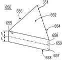
도 6A는 실시태양에 의한 복합 형상화 연마입자의 사시도이다. 도시된 바와 같이, 복합 형상화 연마입자 (600)는 상부 주면 (602) 및 상부 주면 (602)과 대향하는 기저 주면 (603)을 포함하는 몸체 (601)를 가진다. 상부 주면 (602) 및 기저 주면 (603)은 측면들 (606, 605, 604)에 의해 서로 분리된다. 도시된 바와 같이, 형상화 연마입자 (600)의 몸체 (601)는 몸체 (601)의 길이 및 폭에 의해 정의되는 상부 주면 (602)의 평면에서 관찰할 때 삼각형 2차원 형상을 가진다. 상세하게는, 몸체 (601)는 길이 (l), 몸체 (601) 중점 (691)을 통과하여 연장되는 폭 (w), 및 두께 (t)를 가진다. 실시태양에 의하면, 몸체 (601)는 길이:폭의 비율로 정의되는1차 종횡비를 가진다. 소정의 실시예들에서, 몸체 (601)의 1차 종횡비는 적어도 약 1.2:1, 예컨대 적어도 약 1.5:1, 적어도 약 2:1, 적어도 약 3:1, 또는 적어도 약 4:1이다. 또한, 1차 종횡비는 약 100:1 이하이다. 몸체 (601)의1차 종횡비는 상기 임의의 최소 및 최대 비율들 사이의 범위에 있을 수 있다는 것을 이해하여야 한다.6A is a perspective view of a composite shaped abrasive grain according to an embodiment. As shown, the composite shaped
또한, 몸체 (601)는 길이:두께의 비율로 정의되는 2차 종횡비를 가진다. 소정의 실시예들에서, 몸체 (601)의 2차 종횡비는 적어도 약 1.2:1, 예컨대 적어도 약 1.5:1, 적어도 약 2:1, 적어도 약 3:1, 적어도 약 4:1, 적어도 약 5:1, 또는 적어도 약 10:1이다. 또한, 비-제한적인 적어도 하나의 실시태양에서, 몸체 (601)의 2차 종횡비는 약 100:1 이하이다. 2차 종횡비는 상기 임의의 최소 및 최대 비율들 사이의 범위에 있을 수 있다는 것을 이해하여야 한다.Further, the
또한, 몸체 (601)는 폭:두께의 비율로 정의되는 3차 종횡비를 가진다. 소정의 실시예들에서, 몸체 (601)의 3차 종횡비는 적어도 약 1.2:1, 예컨대 적어도 약 1.5:1, 적어도 약 2:1, 적어도 약 3:1, 적어도 약 4:1, 적어도 약 5:1, 또는 적어도 약 10:1이다. 또한, 비-제한적인 적어도 하나의 실시태양에서, 몸체 (601)의 3차 종횡비는 약 100:1 이하이다. 3차 종횡비는 상기 임의의 최소 및 최대 비율들 사이의 범위에 있을 수 있다는 것을 이해하여야 한다.Further, the
본원 실시태양들의 형상화 연마입자들은 몸체 길이에 의해 측정되는 특정 크기를 가진다. 예를들면, 형상화 연마입자들의 중앙 입자크기는 약 5 mm 이하이다. 달리, 중앙 입자 크기는 더 작고, 예컨대 약 4 mm 이하, 약 3 mm 이하, 약 2 mm 이하, 또는 약 1.5 mm 이하이다. 또 다른 양태에서, 형상화 연마입자들의 중앙 입자크기는 적어도 약 10 미크론, 적어도 약 100 미크론, 적어도 약 200 미크론, 적어도 약 400 미크론, 적어도 약 600 미크론, 또는 적어도 약 800 미크론이다. 형상화 연마입자들의 중앙 입자크기는 임의의 상기 최소값 및 최대값 사이의 범위에 있을 수 있다는 것을 이해하여야 한다.The shaped abrasive particles of embodiments herein have a specific size as measured by the body length. For example, the median particle size of the shaped abrasive particles is less than about 5 mm. Alternatively, the median particle size is smaller, such as less than about 4 mm, less than about 3 mm, less than about 2 mm, or less than about 1.5 mm. In yet another embodiment, the median particle size of the shaped abrasive particles is at least about 10 microns, at least about 100 microns, at least about 200 microns, at least about 400 microns, at least about 600 microns, or at least about 800 microns. It should be understood that the median particle size of the shaped abrasive particles can be in the range between any of the above minimum and maximum values.
본원 실시태양들의 형상화 연마입자들은, 특히 알파 알루미나 결정에 대하여 특정 결정 크기를 가진다. 예를들면, 형상화 연마입자들의 평균 결정 크기는 약 500 미크론 이하, 예컨대 약 250 미크론 이하, 또는 약 100 미크론 이하, 약 50 미크론 이하, 약 20 미크론 이하, 또는 약 1 미크론 이하이다. 다른 양태에서, 평균 결정 크기는 적어도 약 0.01 미크론, 예컨대 적어도 약 0.05 미크론, 적어도 약 0.08 미크론, 또는 적어도 약 0.1 미크론이다. 형상화 연마입자들의 평균 결정 크기는 임의의 상기 최소값 및 최대값 사이의 범위에 있을 수 있다는 것을 이해하여야 한다.The shaped abrasive particles of embodiments herein have a particular crystal size, especially for alpha alumina crystals. For example, the average crystal size of the shaped abrasive particles is about 500 microns or less, such as about 250 microns or less, or about 100 microns or less, about 50 microns or less, about 20 microns or less, or about 1 micron or less. In another embodiment, the average crystal size is at least about 0.01 microns, such as at least about 0.05 microns, at least about 0.08 microns, or at least about 0.1 microns. It should be understood that the average crystal size of the shaped abrasive particles can be in the range between any of said minimum and maximum values.
소정의 실시예들에서, 본원 실시태양들의 복합 형상화 연마입자들은 각각의 몸체의 상이한 영역들에서 상이한 재료들을 포함한다. 상세하게는, 소정의 실시예들에서, 복합 형상화 연마입자들은 몸체 내의 상이한 영역들에서 다양한 농도의 도펀트를 포함한다. 예를들면, 도 6A의 복합 형상화 연마입자에 있어서, 몸체 (601)는 층상 구조체로 구성된다. 상세하게는, 몸체는 제1 층 (621), 제1 층 (621) 아래 제2 층 (622), 및 제2 층 (622) 아래 제3 층 (623)을 포함한다. 특정한 경우, 제1 층 (621)은 상부 주면 (602)의 상당 부분을 형성하도록, 더욱 상세하게는 실질적으로 상부 주면의 전체 표면을 형성하도록 구성된다. 또한, 제3 층 (623)은 예를들면, 기저 주면 (603)을 포함하여 몸체의 상당 부분을 형성하도록 구성된다. 특정한 경우, 제3 층 (623)이 실질적으로 몸체 (601) 기저 주면 (603)의 전체 면적을 형성하도록 몸체 (601)가 구성된다.In certain embodiments, the composite shaped abrasive particles of embodiments embodiments include different materials in different regions of each body. Specifically, in certain embodiments, the composite shaped abrasive particles comprise various concentrations of dopants in different regions within the body. For example, in the composite shaped abrasive grain of Fig. 6A, the
특정한 경우, 도시된 바와 같이, 몸체 (601)는 측면들 (604, 605, 606)이 제1 층 (621), 제2 층 (622), 및 제3 층 (623)의 조합으로 형성된다. 각각의 층 (621, 622, 623)은 서로 조성이 다르다. 특정한 경우, 제1 층 (621) 조성은 제2 층 (622) 조성과 적어도 하나의 원소 (element)에 있어서 차별된다. 특정 실시예들에서, 제1 층 (621) 조성은 제2 층 (622) 조성과 특정 도펀트 재료 존재에 여부가 다르다.In certain cases, as shown, the
임의의 층 (621, 622, 623)에서 사용에 적합한 도펀트 재료는 알칼리 금속원소, 알칼리 토금속원소, 희토류 원소, 하프늄, 지르코늄, 니오븀, 탄탈, 몰리브덴, 바나듐, 및 이들의 조합을 포함하는 원소 또는 화합물를 포함한다. 하나의 특정 실시태양에서, 도펀트 재료는 원소 또는 리튬, 나트륨, 칼륨, 마그네슘, 칼슘, 스트론튬, 바륨, 스칸듐, 이트륨, 란탄, 세슘, 프라세오디뮴, 니오븀, 하프늄, 지르코늄, 탄탈, 몰리브덴, 바나듐, 크롬, 코발트, 철, 게르마늄, 망간, 니켈, 티타늄, 아연, 및 이들의 조합과 같은 원소를 포함한 화합물이다.Suitable dopant materials for use in
부분적으로 층을 형성하는 해당 혼합물에 제공되는 도펀트, 또는 인접 층에 있는 도펀트의 함량에 기초하여 임의의 하나의 층 (621, 622, 623)이 특정 함량의 도펀트를 가지도록 몸체 (601)가 형성된다. 특정한 경우, 몸체 (601) 임의의 층들에 있는 도펀트 함량은 층에 존재하는 총 도펀트 함량에 대하여 적어도 약 0.2 wt%, 예컨대 적어도 약 0.6 wt%, 적어도 약 1 wt%, 적어도 약 1.4 wt%, 적어도 약 1.8 wt%, 적어도 약 2 wt%, 적어도 약 2.5 wt%, 적어도 약 3 w%, 적어도 약 3.5 wt%, 적어도 약 4 wt%, 또는 적어도 약 5 wt%이다. 또한, 비-제한적인 하나의 실시태양에 의하면, 임의의 층들 (621, 622, 623)에 있는 도펀트 재료 총 함량은 층 총 중량에 대하여 약 30 wt% 이하, 예컨대 약 26 wt% 이하, 약 24 wt% 이하, 약 20 wt% 이하, 약 18 wt% 이하, 또는 약 16 wt% 이하이다. 임의의 하나의 층의 도펀트 함량은 상기 임의의 최소 비율 및 최대 비율 사이에 있을 수 있다는 것을 이해하여야 한다.The
다른 실시태양에서, 식 [(C1-C2)/C1]x100%로 정의되는 임의의 층들 간의 도펀트 재료 농도 차이는 적어도 5%이고, 식 중 C1은 도펀트 재료의 더 높은 농도의 층이고 C2는 더 낮은 도펀트 재료 농도의 층이다. 다른 실시예들에서, 농도 차이는 더 크고, 예컨대 적어도 약 10%, 적어도 약 20%, 적어도 약 30%, 적어도 약 40%, 적어도 약 50%, 적어도 약 60%, 적어도 약 70%, 적어도 약 80%, 또는 적어도 약 90%. 또한, 다른 실시예들에서, 차이는 약 100% 이하, 예컨대 약 99% 이하, 약 95% 이하, 약 85% 이하, 약 75% 이하, 약 65% 이하, 약 55% 이하, 약 45% 이하, 약 35% 이하, 약 25% 이하, 약 15% 이하, 또는 약 10% 이하이다. 임의의 층들 간 도펀트 농도 차이는 상기 임의의 최소 비율 및 최대 비율 사이에 있을 수 있다는 것을 이해하여야 한다.In another embodiment, the dopant material concentration difference between any of the layers defined by the formula [(C1-C2) / C1] x100% is at least 5%, wherein C1 is a higher concentration layer of dopant material and C2 is more Layer of low dopant material concentration. In other embodiments, the concentration difference is greater, such as at least about 10%, at least about 20%, at least about 30%, at least about 40%, at least about 50%, at least about 60% 80%, or at least about 90%. Also, in other embodiments, the difference is less than or equal to about 100%, such as less than or equal to about 99%, less than or equal to about 95%, less than or equal to about 85%, less than or equal to about 75%, less than or equal to about 65%, less than or equal to about 55% , About 35% or less, about 25% or less, about 15% or less, or about 10% or less. It should be understood that the dopant concentration difference between any of the layers may be between any of the minimum and maximum ratios.
소정의 실시예들에서, 몸체 (601)는 몸체 (601)의 기하학적 중심 (691)을 포함하는 중앙 영역을 가진다. 중앙 영역은 몸체 (601)의 다른 부분들, 예컨대 외면들, 예컨대 상부 주면 (602) 또는 기저 주면 (603)에 비하여 특히 낮은 함량의 도펀트 재료를 가진다. 소정의 실시예들에서, 몸체 (601)의 중앙 영역은 실질적으로 도펀트 재료가 부재이다. 특정 실시태양에 의하면, 몸체 (601) 중앙 영역이 제1 도펀트 농도 (D1C)를 가지고, 몸체 (601)의 기하학적 중심 (691)에서 이격되는 몸체의 주변 영역이 제2 도펀트 농도 (D2C)를 가지도록 몸체 (601)가 형성된다. 소정의 실시예들에서, 몸체 (601)의 중앙 영역은 층 형태이고 몸체 (601)의 상부 주면 (602) 및 기저 주면 (603)과 이격된다. 또한, 중앙 영역은 하나의 측면들, 예컨대 측면 (604, 605, 606) 중 적어도 일부와 교차한다. 도 6A의 특정 실시태양에서, 중앙 영역은 층 (622)에 의해 한정될 수 있다. 이에 따라, 중앙 영역은 상부 주면 (602) 및 기저 주면 (603)과 떨어져 있다. 또한, 중앙 영역은 층 (621)에 의해 한정되는 주변 영역 및 층 (623)에 의해 한정되는 주변 영역 사이에 배치된다. 즉, 중앙 영역은 적어도 부분적으로 주변 영역 (621) 아래에 놓이고 부분적으로 층 (623)에 의해 한정되는 주변 영역 상부에 놓인다.In certain embodiments, the
적어도 하나의 실시태양에서, 주변 영역은 몸체 (601) 주면 예컨대 상부 주면 (602), 기저 주면 (603), 또는 측면 (604, 605, 606)과 교차한다. 특정한 경우, 주변 영역은 몸체 (601) 외면들 중 하나 또는 조합과 교차할 수 있다는 것을 이해하여야 한다. 복합 형상화 연마입자 (600)에 의하면, 주변 영역은 층 (621) 또는 층 (623)에 의해 한정될 수 있다. 이에 따라, 몸체 (601)의 주변 영역은 몸체 (601)의 상부 주면 (602), 및 측면 (604, 605, 606)과 교차하는 층 (621)을 포함한다. 또한, 몸체 (601)는 층 (623)에 의해 한정되고 몸체 (601)의 기저 주면 (603) 및 측면 (604, 605, 606)과 교차하는 제2 주변 영역을 가진다.In at least one embodiment, the peripheral region intersects the main surface, e.g., the top
다른 실시태양에 따르면, 중앙 영역은 몸체 내 주변 영역의 제2 도펀트 농도와는 상이한 제1 도펀트 농도를 가지도록 형성된다. 소정의 실시예들에서, 제1 도펀트 농도는 제2 도펀트 농도보다 크다. 또 다른 실시예들에서, 제2 도펀트 농도는 제1 도펀트 농도보다 크다. 적어도 하나의 실시태양에 따르면, 몸체는 제2 도펀트 농도와 상이한 제1 도펀트 농도를 가지고 따라서 도펀트 농도 차이를 형성한다. 소정의 실시예들에서, 도펀트 농도 차이는 연마체 총중량에 대하여 도펀트 재료 wt% 차이로 측정될 때 적어도 약 0.2 wt%이다. 기타 실시예들에서, 도펀트 농도 차이는 더 크고, 예컨대 적어도 약 0.4 wt%, 적어도 약 0.6 wt%, 적어도 약 1 wt%, 적어도 약 1.4 wt%, 또는 적어도 약 1.8 wt%이다. 또한, 도펀트 농도 차이는 약 30 wt% 이하, 예컨대 약 20 wt% 이하, 약 15 wt% 이하, 예컨대 약 12 wt% 이하, 약 11 wt% 이하, 약 10 wt% 이하, 약 8 wt% 이하, 또는 약 6 wt% 이하이다. 도펀트 농도 차이는 상기 임의의 최소 비율 및 최대 비율 사이에 있을 수 있다는 것을 이해하여야 한다. 또한 임의의 영역에서, 예컨대 주변 영역 또는 중앙 영역에서 총 함량의 도펀트는 임의의 상기 최소율 및 최대율 사이의 범위일 수 있다는 것을 이해하여야 한다.According to another embodiment, the central region is formed to have a first dopant concentration that is different from the second dopant concentration in the peripheral region within the body. In certain embodiments, the first dopant concentration is greater than the second dopant concentration. In still other embodiments, the second dopant concentration is greater than the first dopant concentration. According to at least one embodiment, the body has a first dopant concentration that is different from the second dopant concentration and thus forms a dopant concentration difference. In certain embodiments, the dopant concentration difference is at least about 0.2 wt% when measured as a dopant material wt% difference relative to the total weight of the polishing pad. In other embodiments, the dopant concentration difference is greater, such as at least about 0.4 wt%, at least about 0.6 wt%, at least about 1 wt%, at least about 1.4 wt%, or at least about 1.8 wt%. Also, the dopant concentration difference may be less than or equal to about 30 wt%, such as up to about 20 wt%, up to about 15 wt%, such as up to about 12 wt%, up to about 11 wt%, up to about 10 wt% Or about 6 wt% or less. It should be understood that the dopant concentration difference can be between any of the minimum and maximum rates. It is also to be understood that in any region, for example in the peripheral region or in the central region, the total content of dopants can range between any of the minimum and maximum rates.
도 6B는 실시태양에 의한 복합 형상화 연마입자의 사시도이다. 도시된 바와 같이, 복합 형상화 연마입자 (650)는 상부 주면 (652) 및 상부 주면 (652)과 대향하는 기저 주면 (653)을 포함한 몸체 (651)를 가진다. 상부 주면 (652) 및 기저 주면 (653)은 측면들 (654, 655, 656)에 의해 서로 분리된다. 형상화 연마입자 (650)의 몸체 (651)는 몸체 (651)의 길이 및 폭에 의해 정의되는 상부 주면 (652)의 평면에서 관찰할 때 삼각형 2차원 형상을 가진다. 상세하게는, 몸체 (651)는 본원 실시태양에 기재된 바와 같이 종횡비, 중앙 입자크기, 및 결정 크기를 가지는 형상들을 포함한다.6B is a perspective view of a composite shaped abrasive grain according to an embodiment. As shown, the composite shaped
소정의 실시예들에서, 본원 실시태양들의 복합 형상화 연마입자들은 각각의 몸체 내의 상이한 영역들에서 상이한 재료들을 포함한다. 상세하게는, 소정의 실시예들에서, 복합 형상화 연마입자들은 몸체 내의 상이한 영역들에서 다양한 농도의 도펀트로 구성된다. 임의의 본원 실시태양들에서, 농도는 도펀트 재료의 중량% 또는 부피%로 언급된다. 중량% 또는 부피%는 전체 몸체, 특정 영역, 또는 층의 중량 또는 부피를 기준으로 한다.In certain embodiments, the composite shaped abrasive particles of embodiments embodiments include different materials in different regions within each body. Specifically, in certain embodiments, the composite shaped abrasive particles are comprised of various concentrations of dopants in different regions within the body. In any of the embodiments herein, the concentration is referred to as weight percent or volume percent of the dopant material. Weight percent or volume percent is based on the weight or volume of the entire body, area, or layer.
예를들면, 도 6B의 복합 형상화 연마입자에 있어서, 몸체 (651)는 층상 구조체로 구성된다. 몸체는 제1 층 (657) 및 제1 층 (657) 아래의 제2 층 (658)을 포함한다. 특정한 경우, 제1 층 (657)은 기저 주면 (653)의 상당 부분을 형성하도록, 더욱 상세하게는, 실질적으로 기저 주면 (653) 전체 외면을 형성하도록 형성된다. 또한, 일 실시태양에서, 제2 층 (658)은 몸체 (651) 상당 부분 예를들면, 상부 주면 (652)을 형성하도록 형성된다. 특정한 경우, 몸체 (651)는 제2 층 (658)이 몸체 (651) 상부 주면 (652) 면적의 적어도 일부를 형성하도록 구성된다. 하나의 특정 실시태양에서, 제1 층 (657)은 제2 층 (658)과 직접 접촉된다.For example, in the composite shaped abrasive grain of Fig. 6B, the
제1 층 (657)은 몸체 (651)의 전체 길이 및 폭에 대하여 연장되고 몸체 (651) 외면들의 실질적 부분을 형성하는 실질적으로 평면 구조체를 가진다. 또한, 제1 층 (658)은 몸체 (651)의 전체 길이 및 폭에 대하여 연장되고 몸체 (651) 외면들의 실질적 부분을 형성하는 실질적으로 평면 구조체를 가진다.The
특정한 경우, 도시된 바와 같이, 측면들 (654, 655, 656)이 제1 층 (657) 및 제2 층 (658)의 조합으로 형성되도록 몸체 (651)가 구성된다. 도시된 바와 같이, 몸체 (651)는 제1 층 (657)이 제1 두께 (t1)를 가지고 제2 층 (658)이 제2 두께 (t2)를 가지도록 형성된다. 특정 실시태양에서, 제1 두께 및 제2 두께는 실질적으로 동일하다. 기타 실시예들에서, 제1 두께 및 제2 두께는 실질적으로 상이하다. 예를들면, 제1 두께 및 제2 두께는 서로 적어도 약 5%, 적어도 약 10%, 적어도 약 20%, 또는 적어도 약 30% 상이하다. 또한, 비-제한적 일 실시태양에서, 제1 두께 및 제2 두께는 서로 약 90% 이하, 예컨대 약 80% 이하, 약 70% 이하, 약 50% 이하로 상이하다. 제1 두께 및 제2 두께 간의 두께 차이는 임의의 상기 최소율 및 최대율 사이의 범위일 수 있다는 것을 이해하여야 한다.The
하나의 실시태양에 따르면, 제1 두께는 몸체 평균 두께의 적어도 약 5%이다. 다른 실시예들에서, 제1 두께는 더 두껍고, 예컨대 적어도 약 10%, 적어도 약 20%, 적어도 약 30%, 적어도 약 40%, 또는 적어도 약 50%이다. 비-제한적 일 실시태양에서, 제1 두께는 몸체 평균 두께의 약 99% 이하, 예컨대 약 90% 이하, 약 80% 이하, 약 70% 이하, 약 60% 이하, 약 50% 이하, 약 40% 이하, 또는 약 30% 이하이다. 제1 두께는 상기 임의의 최소 비율 및 최대 비율 사이에 있을 수 있다는 것을 이해하여야 한다. 또한, 제2 두께는 몸체 평균 두께에 대하여 제1 두께와 동일한 속성들을 가진다. 또한, 기타 추가 층들, 예컨대 중간 층은, 동일한 특징부들을 가질 수 있다.According to one embodiment, the first thickness is at least about 5% of the body average thickness. In other embodiments, the first thickness is thicker, such as at least about 10%, at least about 20%, at least about 30%, at least about 40%, or at least about 50%. In one non-limiting embodiment, the first thickness is less than about 99%, such as less than about 90%, less than about 80%, less than about 70%, less than about 60%, less than about 50% Or less, or about 30% or less. It should be appreciated that the first thickness may be between any of the minimum and maximum ratios. Also, the second thickness has properties equal to the first thickness with respect to the body average thickness. In addition, other additional layers, such as an intermediate layer, may have the same features.
각각의 층 (657, 658)은 조성에 있어서 서로 다르다는 것을 이해하여야 한다. 특정한 경우, 제1 층 (657) 조성은 제2 층 (658) 조성과 적어도 하나의 원소만큼 다르다. 특정 실시예들에서, 제1 층 (657) 조성은 제2 층 (658) 조성과 적어도 하나의 도펀트 재료 또는 다수의 도펀트 재료들에 있어서 다르다.It should be understood that each
임의의 층들 (657, 658)에서 사용에 적합한 도펀트 재료는 원소 또는 화합물 예컨대 알칼리 금속원소, 알칼리 토금속원소, 희토류 원소, 하프늄, 지르코늄, 니오븀, 탄탈, 몰리브덴, 바나듐, 또는 이들의 조합을 포함한다. 하나의 특정 실시태양에서, 도펀트 재료는 원소 또는 원소 예컨대 리튬, 나트륨, 칼륨, 마그네슘, 칼슘, 스트론튬, 바륨, 스칸듐, 이트륨, 란탄, 세슘, 프라세오디뮴, 니오븀, 하프늄, 지르코늄, 탄탈, 몰리브덴, 바나듐, 크롬, 코발트, 철, 게르마늄, 망간, 니켈, 티타늄, 아연, 및 이들의 조합을 포함한 화합물을 포함한다.Suitable dopant materials for use in any of the
임의의 하나의 층들 (657, 658)이 서로에 대하여 상이한 함량의 도펀트를 가지도록 몸체 (651)가 형성된다. 소정의 실시예들에서, 제1 층 (657)은 몸체 (601)의 기하학적 중심 (602)을 포함한 몸체 (651) 중앙 영역을 가진다. 다른 실시태양들에서, 제2 층 (658)은 몸체 (651) 주변 영역을 포함한다. 하나의 실시태양에 따르면, 제1 층 (657)은 제1 도펀트 농도 (D1C)를 가지고 제2 층은 제2 도펀트 농도 (D2C)를 가진다. 기타 실시태양에 따르면, 제1 층 (657)은 몸체 내의 제2 층 (658) 제2 도펀트 농도와는 상이한 제1 도펀트 농도를 가진다. 소정의 실시예들에서, 제1 도펀트 농도는 제2 도펀트 농도보다 높다. 또 다른 예시적 몸체들에서, 제2 도펀트 농도는 제1 도펀트 농도보다 높다. 적어도 하나의 실시태양에 의하면, 몸체 (651)는 제2 도펀트 농도와 상이한 제1 도펀트 농도를 가지고 따라서 도펀트 농도 차이 (ΔDc)를 형성한다.The
특정한 경우, 몸체 (651) 두 층들 (657, 658) 간의 도펀트 농도 차이 (ΔDc)는 몸체 (651) 내 존재하는 도펀트 총 함량에 대하여 적어도 약 0.2 wt%, 예컨대 적어도 약 0.6 wt%, 적어도 약 1 wt%, 적어도 약 1.4 wt%, 적어도 약 1.8 wt%, 적어도 약 2 wt%, 적어도 약 2.5 wt%, 적어도 약 3 w%, 적어도 약 3.5 wt%, 적어도 약 4 wt%, 또는 적어도 약 5 wt%이다. 또한, 비-제한적인 하나의 실시태양에 의하면, 임의의 하나의 층 (657, 658) 간 도펀트 재료 함량 총 차이는 연마체 총중량에 대하여 약 30 wt% 이하, 약 26 wt% 이하, 약 24 wt% 이하, 약 20 wt% 이하, 약 18 wt% 이하, 또는 약 16 wt% 이하이다. 임의의 하나의 층 사이 도펀트 재료 함량 차이는 상기 임의의 최소 비율 및 최대 비율 사이에 있을 수 있다는 것을 이해하여야 한다. 본원에 기재된 바와 같이, 상기 중량%는 몸체 중량 기준으로 언급되지만, 동일한 백분율이 상응하는 층들의 중량을 기준할 수 있다는 것을 이해하여야 한다. 예를들면, 제1 층 (657)이 도펀트 층 총 중량에 대하여 5 wt%를 가지고 제2 층 (658)이 층 총 중량에 대하여 2 wt%의 동일한 도펀트을 가지면, 두 층들 사이 중량% 차이는 3 wt%로 계산될 수 있다.In certain cases, the
다른 실시태양에서, 식 [(C1-C2)/C1]x100%으로 계산되는 층들 (657, 658) 사이 도펀트 재료 농도 차이는 적어도 5%이고, 식 중 C1은 더 높은 농도의 도펀트 재료 층이고C2 는 더 낮은 도펀트 재료 농도의 층이다. 다른 실시예들에서, 농도 차이는 더 크고, 예컨대 적어도 약 10%, 적어도 약 20%, 적어도 약 30%, 적어도 약 40%, 적어도 약 50%, 적어도 약 60%, 적어도 약 70%, 적어도 약 80%, 또는 적어도 약 90%이다. 또한, 다른 실시예들에서, 차이는 약 100% 이하, 예컨대 약 99% 이하, 약 85% 이하, 약 75% 이하, 약 65% 이하, 약 55% 이하, 약 45% 이하, 약 35% 이하, 약 25% 이하, 약 15% 이하, 또는 약 10% 이하이다. 임의의 층들 사이 도펀트 농도 차이는 상기 임의의 최소 비율 및 최대 비율 사이에 있을 수 있다는 것을 이해하여야 한다.In another embodiment, the dopant material concentration difference between the
하나의 실시태양에 따르면, 제2 층 (658)은 지르코늄을 포함한 제2 도펀트를 포함한다. 상세하게는, 제2 도펀트는 지르코니아를 포함하고, 더욱 상세하게는, 실질적으로 지르코니아로 이루어진다. 소정의 실시태양들에서, 제2 층 (658)은 제1 층 (657)의 지르코니아 함량보다 더 많은 함량의 지르코니아를 포함한다. 다른 실시태양에서, 제1 층 (657) 및 제2 층 (658) 간의 지르코니아 도펀트 농도 차이는 적어도 약 0.2 wt%, 예컨대 적어도 약 0.5 wt%, 적어도 약 1 wt%, 적어도 약 1.4 wt%, 적어도 약 1.8 wt%, 또는 적어도 약 2 wt%이다. 또한, 비-제한적인 하나의 실시태양에 의하면, 임의의 하나의 층 (657, 658) 사이 도펀트 재료 함량의 총 차이는 연마체 총중량에 대하여 약 50 wt% 이하, 예컨대 약 30 wt% 이하, 약 25 wt% 이하, 약 20 wt% 이하, 약 15 wt% 이하, 또는 약 12 wt% 이하이다. 제1 층 (657) 및 제2 층 (658) 간의 지르코니아 도펀트 재료 함량 차이는 상기 임의의 최소 비율 및 최대 비율 사이에 있을 수 있다는 것을 이해하여야 한다.According to one embodiment, the
하나의 특정 양태에 의하면, 제1 층 (657)은 제2 층 (658)의 제2 도펀트와는 상이한 제1 도펀트를 포함하고, 더욱 상세하게는, 제1 층 (657)은 제2 층 (658)에 존재하는 제2 도펀트 재료가 실질적으로 부재이다. 유사하게, 소정의 실시예들에서, 제2 층 (658)은 제1 층 (657)의 제1 도펀트와 상이한 제2 도펀트를 포함하고, 더욱 상세하게는, 제2 층 (658)은 제1 층 (657)에 존재하는 제1 도펀트 재료가 실질적으로 부재이다.According to one particular embodiment, the
또한, 다른 실시태양들에서, 도펀트는 공정 중에 하나의 인접 층에서 다른 층으로 확산된다. 상세하게는, 제어된 공정을 통해서 층들 간의 도펀트 확산을 제어할 수 있고, 초기에 단일 층에 존재하는 도펀트 재료는 하나 이상의 인접 층들로 전달되도록 제어되어 특정 도펀트들을 가지는 적합한 복합 형상화 연마입자가 형성되거나, 계단 함수 확산 경계들을 보인다.Also, in other embodiments, the dopant diffuses from one adjacent layer to another during the process. In detail, the dopant diffusion between the layers can be controlled through a controlled process, and the dopant material initially present in a single layer is controlled to be delivered to one or more adjacent layers to form a suitable composite shaped abrasive particle with specific dopants , And step boundary diffusion boundaries.
몸체 (651)는 대략 삼각형 2차원 형상의 제1 층 (657) 및 제1 층 (657)에 적층되고 및 실질적으로 유사한 삼각형 2차원 형상을 가지는 제2 층 (658)을 포함하는 것으로 도시되지만, 본원 실시태양들의 복합 몸체들은 다중 층들을 포함할 수 있고, 각각의 층은 서로에 대하여 상이한 2차원 형상들을 가질 수 있다는 것을 이해하여야 한다. 예를들면, 도 20A에 도시된 바와 같이, 형상화 연마입자는 몸체 (2001)를 가지도록 구성되고, 몸체는 몸체 (2001) 길이 및 폭에 의해 정의되는 평면에서 관찰할 때 제1의 2차원 형상을 가지는 제1 층 (2002) 및 제2의 2차원 형상을 가지고 제1 층 (2002)에 적층되는 제2 층 (2003)을 포함한다. 상세하게는, 도시된 바와 같이, 제1 층 (2002)은 대략 다각 2차원 형상을 가지고 제2 층 (2003)은 대략 타원형 또는 원형 2차원 형상을 가진다.The
도 20B는 제1의 2차원 형상을 가지는 제1 층 (2005) 및 제2의 2차원 형상을 가지는 제2 층 (2006)을 포함하는 형상화 연마입자 (2004)을 가지는 기타 실시태양을 도시한 것이다. 도 20A 및 20B는 예시적인 것이고, 본원 실시태양들의 형상화 연마입자들은 제한적이지 않지만 다각형, 타원형, 숫자, 그리스 알파벳 문자, 라틴 알파벳 문자, 러시아 알파벳 문자, 다각형들의 조합인 복잡 형상, 또는 이의 조합, 모서리가 잘린 형상들, 및 이들의 조합을 포함한 여러 상이한 2차원 형상들을 포함한 다수의 층들을 포함할 수 있다는 것을 이해하여야 하고, 몸체는 길이 및 폭에 의해 정의되는 평면에서 관찰할 때 다각형으로 구성되고, 몸체는 삼각, 직사각, 사각, 오각, 육각, 칠각, 팔각, 구각, 십각, 임의의 이들의 조합의 군에서 선택되는 다각형으로 구성된다. 상기는 모서리가 잘린 형상들을 포함하고, 이는 모서리의 적어도 일부가 손실되거나 형상 변경된 것이고, 이는 소정의 처리 기술에 의한 결과이다.Figure 20B illustrates another embodiment having shaped
또한, 도 20A 및 20B에서 명백한 바와 같이, 형상화 연마입자들은 층들의 조합을 포함하고, 각각의 층은 서로 상이한 2차원 형상들을 가지고 층들의 임의의 하나의 치수에 대하여 상이한 치수적 형상들을 가질 수 있다. 이러한 형상화 연마입자들로 인하여 연마물품에서 입자들 전개가 개선되고 연마물품 성능 또는 사용이 개선된다. 예를들면, 제1 층 (2002)의 2차원 형상에서의 평균 길이 (또는 직경)는 제2 층 (2003)의 2차원 형상에서의 평균 길이 (또는 직경)와 상당히 다르다. 또한 제1 층 (2002)의 2차원 형상에서의 평균 폭은 제2 층 (2003)의 2차원 형상에서의 평균 폭과는 상당히 다르다. 또한 제1 층 (2002)의 2차원 형상에서의 평균 두께는 제2 층 (2003)의 2차원 형상에서의 평균 두께와 상당히 다르다.In addition, as is apparent in Figs. 20A and 20B, the shaped abrasive particles comprise a combination of layers, and each layer may have different two-dimensional shapes and have different dimensional shapes for any one dimension of the layers . These shaped abrasive particles improve particle development in the abrasive article and improve the abrasive article performance or use. For example, the average length (or diameter) in the two-dimensional shape of the
도 20A 및 20B에서 더욱 도시된 바와 같이, 각각의 층은 서로 상이한 면적 또는 부피를 가진다. 예를들면, 제1 층 (2002) 2차원 형상의 평균 면적 (예를들면, 주 (major) 외면의 평균 표면적)은 제2 층 (2003) 2차원 형상의 평균 면적과 상당히 다르다. 또한, 제1 층 (2002) 2차원 형상의 평균 부피는 제2 층 (2003) 2차원 형상의 평균 부피와 상당히 다르다. 예를들면, 제1 층 (2002)의 부피는 제2 층 (2003) 부피보다 상당히 커서, 제1 층 (2002)은 제2 층 (2003)보다 몸체 (2001) 총 부피의 더 많은 부분을 차지한다. 또한, 대안적 실시태양들에서, 제1 층 (2002)의 부피는 제2 층 (2003) 부피보다 더 작다.As further shown in Figures 20A and 20B, each layer has a different area or volume from each other. For example, the average area of the
다시 도 6B를 참조하면, 몸체는 제1 층 (657) 및 제2 층 (658) 사이에 확산 계면 (interface, 659)을 포함한다. 일 실시태양에서, 확산 계면 (659)은 제1 층 (657) 및 제2 층 (658)의 경계를 형성한다. 또한, 확산 계면 (659)은 제1 층 (657) 및 제2 층 (658)을 분리한다. 하나의 실시태양에 따르면, 몸체 (651)는 제1 층 (657) 및 제2 층 (658) 사이 확산 경계를 형성하는 확산 계면 (659)을 가지고, 확산 계면 (659) 제1 측 (예를들면, 제1 층 (657) 내부)에서의 적어도 하나의 도펀트 농도는 확산 계면 (659)의 대향 측 (예를들면, 제2 층 (658) 내부)에서의 동일한 도펀트의 농도와는 상당히 다르다. 확산 계면 (659)은 제1 층 (657) 및 제2 층 (658) 사이 하나 이상의 도펀트 농도 차이를 특정하는 경계를 형성할 수 있다는 것을 이해하여야 한다. 소정의 실시예들에서, 확산 계면 (659)은 제1 층 (657) 및 제2 층 (658) 간 적어도 하나의 도펀트의 농도에 있어서 계단 함수 차이를 형성하고, 예를들면, 제1 층 (657) 제2 도펀트 농도와 비교하여 제2 층 (568) 제2 도펀트 농도의 계단 함수 차이를 형성한다.Referring again to FIG. 6B, the body includes a
확산 계면 (659)은 제1 층 (657) 및 제2 층 (658) 사이 전체 면적에 걸쳐 연장된다. 소정의 실시예들에서, 확산 계면 (659)은 몸체 (651) 전체 길이에 걸쳐 연장된다. 또한, 확산 계면 (659)은 몸체 (651) 전체 폭에 연장된다. 확산 계면 (659)은 평면 외곽선 또는 달리, 만곡, 아치, 또는 불규칙한 외곽선을 가질 수 있다는 것을 이해하여야 한다. 확산 계면 (659)의 형태 및 방향은 확산 계면을 형성하는 해당 층들 또는 부분들의 형상 및 배향에 부분적으로 의존한다.The
다른 양태에 따르면, 다중 부분들, 예컨대 제1 층 (657) 및 제2 층 (658)을 가지는 형상화 연마입자는 하나의 부분 (또는 층)이 제2, 인접 부분에 대하여 압축되고, 및 제2 부분은 해당 및 인접 부분에 대하여 인장 상태가 되도록 형성될 수 있다. 예를들면, 도 6B의 형상화 연마입자에서, 제1 층 (657)은 제2 층 (658)에 대하여 압축되고 및 제2 층 (658)은 제1 층 (657)에 대하여 인장 상태를 유지한다. 달리, 제2 층 (658)은 제1 층 (657)에 대하여 압축될 수 있다.According to another aspect, the shaped abrasive particles having multiple portions, such as a
형상화 연마입자 몸체의 하나 이상의 부분들 (예를들면, 층들 (657, 658))에 대한 상대적인 압축 및 인장 상태는 서로에 대한 형상, 치수, 및 조성 중 적어도 하나를 선택함으로써 제어될 수 있다. 특정한 경우, 형상화 연마입자 몸체는 제1 부 및 제2 부 간의 응력 (또는 변형) 차이가 적어도 약 5%, 예컨대 적어도 약 10%, 적어도 약 20%, 적어도 약 30%, 적어도 약 40%, 적어도 약 50%, 적어도 약 60%, 적어도 약 70%, 적어도 약 80% 또는 적어도 약 90%이 되도록 형성된다. 또한, 다른 실시예에서, 제1 부 및 제2 부 간의 응력 (또는 변형) 차이는 약 90% 이하, 예컨대 약 80% 이하, 약 70% 이하, 약 60% 이하, 예컨대 약 50% 이하, 약 40% 이하, 약 30% 이하, 예컨대 약 20% 이하, 약 10% 이하, 또는 약 5% 이하이다. 몸체의 제1 부 및 제2 부 간의 응력 (또는 변형) 차이는 상기 임의의 최소 비율 및 최대 비율 사이에 있을 수 있다는 것을 이해하여야 한다.The relative compression and tension conditions for one or more portions (e.g., layers 657, 658) of the shaped abrasive grain body can be controlled by selecting at least one of shape, dimensions, and composition for each other. In certain instances, the stylized abrasive grain body has a stress (or deformation) difference between the first and second portions of at least about 5%, such as at least about 10%, at least about 20%, at least about 30%, at least about 40% , At least about 50%, at least about 60%, at least about 70%, at least about 80%, or at least about 90%. Also, in other embodiments, the stress (or strain) difference between the first and second portions may be less than or equal to about 90%, such as less than about 80%, less than about 70%, less than about 60%, such as less than about 50% About 40% or less, about 30% or less, such as about 20% or less, about 10% or less, or about 5% or less. It should be understood that the stress (or strain) difference between the first and second portions of the body can be between any of the minimum and maximum ratios.
본원에 기재된 바와 같이, 몸체 (651)는 추가 부분들 또는 층들을 포함할 수 있다. 예를들면, 몸체 (651)는 제1 층 (657) 및 제2 층 (658) 사이 적어도 하나의 중간 층을 포함한다. 중간 층은 제1 층 (657)과 실질적으로 동일한 조성을 가진다. 또한, 중간 층은 제2 층 (658)과 실질적으로 동일한 조성을 가진다. 달리, 중간 층은 제1 층 조성과 비교할 때 실질적으로 상이한 조성을 가지고, 도펀트 재료에 있어서 적어도 하나의 차이를 포함한다. 유사하게, 중간 층은 제2 층 조성과 비교할 때 실질적으로 상이한 조성을 가지고, 도펀트 재료에 있어서 적어도 하나의 차이를 포함한다.As described herein, the
중간 층은 제1 층 (657) 및 제2 층 (658) 사이에 배치되고 상기 확산 계면과 더불어 추가적인 확산 계면을 형성한다. 따라서, 몸체는 제1 층 및 중간 층 사이에 제1 확산 계면 (예를들면, 제1 중간 확산 계면) 및 중간 층 및 제2 층 (658) 사이 제2 확산 계면 (예를들면, 제2 중간 확산 계면을 가진다. 모든 확산 계면들은 본원 실시태양들에 따라 기재된 확산 계면들의 특성들을 가진다.The intermediate layer is disposed between the
도 7은 실시태양에 의한 형상화 연마입자의 사시도이다. 복합체 형상화 연마입자 (700)는 상부 주면 (702), 측면들 (704, 705, 706)에 의해 상부 주면 (702)과 분리되는 기저 주면 (703)을 가지는 몸체 (701)를 포함한다. 복합 형상화 연마입자 (700)는 대안적 복합 재료 층들의 배열을 나타내고, 특히 몸체 (701) 내의 상이한 층들의 코어-쉘 배열을 나타낸다. 하나의 실시태양에 따르면, 몸체 (701)는 측면들 (704, 705, 706)을 포함한 몸체 외부 측면들을 교차하는 제1 층 (721)을 포함한다. 특정한 경우, 제1 층 (721)은 외부 측면들 (704, 705, 706)을 교차하고 형성한다. 도시된 바와 같이, 제1 층 (721)은 적어도 상부 주면 (702) 및 기저 주면 (703) 일부를 형성한다. 실제로, 도시된 바와 같이, 제1 층 (721)은 대략 환형 형상을 가지고, 제2 층 (723) 및 제3 층 (724)은 제1 층 (721) 내부에 배치된다.7 is a perspective view of a shaped abrasive grain according to an embodiment. The composite shaping
도시된 바와 같이, 몸체는 층 (721)에 의해 한정되는 주변 영역이 다른 영역, 예컨대 복합 형상화 연마입자의 중앙 영역을 한정하는 다른 층의 적어도 일부를 포위하도록 형성된다. 또한, 몸체 (701)는 제1 층 (721) 내부에 배치되는 제2 층 (723)을 포함한다. 제2 층 (723) 일부는 상부 주면 (702)과 교차한다. 또한, 제2 층 (723) 일부는 기저 주면 (703)과 교차한다. 실제로, 제2 층 (723) 일부는 상부 주면 (702) 및 기저 주면 (703)의 일부와 교차하고 이를 형성한다. 특히, 제2 층 (723)은 몸체 외면, 예컨대 외부 측면들 (704, 705, 706)의 적어도 일부와 이격된다. 실시태양에 의하면, 제2 층은 제1 층 (721) 조성과는 다른 조성을 가지는 중앙 영역을 한정할 수 있다. 특정한 경우, 제2 층 (723)은 기타 본원 실시태양들에 기재된 바와 같이 제1 층 (721)의 도펀트 농도와는 다른 도펀트 농도를 가지는 몸체 (701) 중앙 영역을 한정할 수 있다. 또한, 제2 층 (723)은 제1 층 (721) 및 제3 층 (724) 사이 중간 층을 한정할 수 있다.As shown, the body is formed such that the peripheral region defined by
도시된 바와 같이, 복합 형상화 연마입자 (700)는 제2 층 (723) 및 제1 층 (721) 내부에 배치되는 제3 층 (724)을 가지는 몸체를 포함한다. 제3 층 (724)은 중앙 영역을 나타내고 몸체 (701)의 부피 중점을 나타내는 몸체 의 기하학적 중심(704)을 포함한다. 실시태양에 의하면, 제3 층 (724)은 예를들면 외부 측면들 (704, 705, 706)을 포함한 몸체의 하나 이상의 외면들에서 이격되는 중앙 영역을 나타낸다. 또한, 제3 층 (724)은 상부 주면 (702) 및 저면 (703) 일부와 교차하고 이를 형성하는몸체 (701) 중앙 영역을 나타낸다. 그러나 제3 층 (724)은 반드시 몸체 (701) 외면들의 임의의 일부를 형성하고 교차할 필요는 없고 임의의 외면들과 떨어져 전적으로 내부에 유지될 수 있다는 것을 이해하여야 한다.As shown, the composite shaped
실시태양에 의하면, 몸체는 주변 영역 부피비(volume portion)와 비교하여 몸체 총 부피에 대한 특정 부피비 (부피 %)로 구성되는 중앙 영역을 포함한다. 예를들면, 몸체 (701)는 주변 영역 부피비와 비교하여 몸체 총 부피 중 더 작은 부피비로 구성되는 중앙 영역을 포함한다. 또한, 대안적 실시태양들에서, 몸체 (701)는 중앙 영역이 주변 영역 부피비와 비교하여 몸체 총 부피의 더 많은 부피비를 가지도록 구성된다.According to an embodiment, the body comprises a central region consisting of a specific volume fraction (volume%) relative to the total volume of the body as compared to the volume area of the peripheral region. For example, the
도 8은 실시태양에 의한 복합 형상화 연마입자의 사시도이다. 도시된 바와 같이, 복합 형상화 연마입자 (800)는 상부 주면 (802) 및 측면들 (804, 805, 806)에 의해 상부 주면 (802)과 분리되는 기저 주면 (803)을 가지는 몸체 (801)를 포함한다. 상기 실시태양들은 대략 대칭적 형상들을 가지는 주변 영역들 및 중앙 영역들을 보이지만, 본원 실시태양들의 대안적 복합 연마입자들은 비-대칭 형상들을 가지는 주변 영역들 및 중앙 영역들이 적용된다. 예를들면, 도 8에 도시된 바와 같이, 몸체는 상부 주면 (802), 기저 주면 (803), 및 측면들 (804, 805, 806)을 포함한 다양한 외면들의 일부와 교차하고 이를 형성하는 제2 층 부분들 (823)의 무작위 배열을 포함한다. 또한, 몸체 (801)는 몸체 (801)의 기하학적 중심 (891)을 가지는 제1 층 (821)을 포함한다.8 is a perspective view of a composite shaped abrasive grain according to an embodiment. As shown, the composite shaped
또한, 제1 층 (821)은 예를들면, 상부 주면 (802), 기저 주면 (803), 및 측면들 (804, 805, 806)을 포함한 몸체 (801) 외면들의 다양한 부분들과 교차하고 이를 형성한다. 특정한 경우, 제1 층 (821)은 대부분의 몸체 (801)를 관통 연장하는 연속 상 또는 매트릭스를 한정할 수 있고, 제2 층 일부들은 서로 떨어진 분산 및 개별 영역들로 존재한다. 이에 따라, 하나의 특정 실시태양에서, 제1 층 (821)은 몸체의 중앙 영역을 나타낸다. 또한, 소정의 실시예들에서, 제2 층 부분들 (823)은 몸체(801)의 주변 영역들을 한정할 수 있다.The first layer 821 also intersects the various portions of the outer surfaces of the
실시태양에 의하면, 몸체 (801) 중앙 영역을 형성하는 제1 층 (821)은 비-대칭 형상을 가진다. 몸체 (801) 길이 및 폭또는 달리, 몸체 (801) 폭 및 두께에 의해 정의되는 평면에서 비-대칭 형상으로 관찰된다. 또한, 몸체 (801)는 주변 영역들을 형성하는 제2 층들 부분들 (823)을 포함하고, 주변 영역들은 비-대칭 형상들을 가진다. 특정한 경우, 제2 층 부분들 (823)에 의해 형성되는 주변 영역들은 몸체 (801) 길이 및 폭에 의해 정의되는 평면 또는 몸체 (801) 폭 및 두께에 의해 정의되는 평면에서 관찰할 때 비-대칭적 형상들을 가진다.According to an embodiment, the first layer 821 forming the central region of the
도 9는 실시태양에 의한 형상화 연마입자의 부분 단면도이다. 특히, 형상화 연마입자는 몸체 (901)를 포함하고, 이는 저면 (904), 저면 (904)에 대향되는 상부 주면 (902), 및 저면 (904) 및 상부 주면 (902)을 연결하는 측면 (903)을 가진다. 도시된 바와 같이, 몸체 (901)는 측면 (903)에 대향되고 저면 (904) 및 상부 주면 (902)을 연결하는 측면 (905)을 포함한다. 특정 실시태양에 의하면, 몸체 (901)는 곡선의 상부 주면 (902)을 가진다. 특히, 일부 실시예들에서, 상부 주면 (902)는 볼록 외곽선을 가지므로 중점에서의 몸체 (901) 두께(tm)는 하나의 측면들 (903, 905)에서의 두께 (ts)보다 크다. 일부 실시태양들에서, 저면 (902)은 상부 주면 (902)과 비교하여 실질적으로 평탄하다.9 is a partial cross-sectional view of a shaped abrasive grain according to an embodiment. In particular, the shaped abrasive particles comprise a
도 10은 실시태양에 의한 대안적 형상화 연마입자의 단면도이다. 특히, 형상화 연마입자는 몸체 (1001)를 포함하고, 이는 저면 (1004), 저면 (1004)에 대향되는 상부 주면 (1002), 및 서로 대향되고 저면 (1004) 및 상부 주면 (1002)을 연결하는 측면들 (1003, 1005)을 가진다. 도시된 바와 같이, 몸체 (1001)는 특히 특유한 외곽선을 가지고, 상부 주면 (1002)은 볼록 외곽선을 가지며, 저면 (1004) 역시 볼록 외곽선을 가지므로 중점에서의 두께 (tm)는 표면들 (1001, 1005)에 의해 정의되는 가장자리들에서의 몸체 (1001) 두께 (te)보다 상당히 크다.10 is a cross-sectional view of an alternative shaped abrasive grain according to an embodiment. In particular, the shaped abrasive particles comprise a
도 11은 실시태양에 의한 대안적 형상화 연마입자의 단면도이다. 특히, 형상화 몸체 (1101)를 포함하고, 이는 저면 (1104), 저면 (1104)에 대향되는 상부 주면 (1102), 및 서로 대향되고 저면 (1104) 및 상부 주면 (1102)을 분리하는 측면들 (1103, 1105)을 가진다. 도시된 바와 같이, 몸체 (1101)는 특유한 외곽선을 가지고, 상부 주면 (1102)은 오목 외곽선을 가지고 저면 (1104)은 실질적으로 평면 외곽선을 가지므로 중점에서의 두께 (tm)는 표면들 (1101, 1105)에 의해 정의되는 가장자리들에서의 몸체 (1101) 두께 (te) 보다 상당히 작다.11 is a cross-sectional view of an alternative shaped abrasive grain according to an embodiment. In particular, it includes a
도 12는 실시태양에 의한 대안적 형상화 연마입자의 단면도이다. 특히, 형상화 연마입자는 몸체 (1201)를 가지고, 이는 저면 (1204), 저면 (1204)에 대향되는 상부 주면 (1202), 및 서로 대향되고 저면 (1204) 및 상부 주면 (1202)을 분리하는 측면들 (1203, 1205)을 가진다. 도시된 바와 같이, 몸체 (1201)는 특유한 외곽선을 가지고, 상부 주면 (1202)은 오목 외곽선을 가지며 저면 (1204)은 오목 외곽선을 가지므로 중점에서의 두께 (tm)는 가장자리들에서의 몸체 (1201) 두께 (te) 보다 상당히 작다.12 is a cross-sectional view of an alternative shaped abrasive grain according to an embodiment. In particular, the shaped abrasive particles have a
실시태양에 의하면, 본원 실시태양들의 형상화 연마입자들은 적어도 두 개의 외면들이 서로 상당히 다른 2차원 형상들을 가지도록 형성된다. 상세하게는, 형상화 연마입자들은 상부 주면의 2차원 형상과는 상당히 다른2차원 형상을 가지는 기저 주면을 포함한다. 더욱 특정한 실시태양들에서, 2차원 형상들은 본원 실시태양들에 기재된 임의의 하나의 2차원 형상들일 수 있다. 예를들면, 저면은 제1 다각형일 수 있고 상부 주면은 상이한 다각형일 수 있다.According to an embodiment, the shaped abrasive particles of the embodiments herein are formed such that at least two outer surfaces have significantly different two-dimensional shapes from one another. Specifically, the shaped abrasive particles include a base peripheral surface having a two-dimensional shape that is significantly different from the two-dimensional shape of the upper major surface. In more specific embodiments, the two-dimensional shapes may be any one of the two-dimensional shapes described in the embodiments herein. For example, the bottom surface can be a first polygon and the top major surface can be a different polygon.
도 13은 실시태양에 의한 형상화 연마입자의 사시도이다. 형상화 연마입자 (1300)는 몸체 (1301)를 가지고, 이는 저면 (1304) 및 저면 (1304)과 측면들 (1305, 1306, 1307)에 의해 분리되는 상면 (1303)을 가진다. 도 13에 도시된 바와 같이, 저면 (1304)은 대략 삼각형이지만, 상면 (1303)은 타원 형상을 가진다.13 is a perspective view of a shaped abrasive grain according to an embodiment. The shaped abrasive particles 1300 have a
도 14A는 실시태양에 의한 형상화 연마입자의 사시도이다. 특히, 몸체 (1401)는 제1 장측 (1402), 제2 장측 (1403), 및 제3 장측 (1404)을 가진다. 또한, 몸체 (1401)는 제1 장측 (1402) 및 제2 장측 (1403)과 연결되는 제1 단측 (1405)을 포함한다. 몸체 (1401)는 제1 장측 (1402) 및 제3 장측 (1404)과 연결되는 제2 단측 (1406)을 더욱 포함한다. 형상화 연마입자 몸체 (1401)는 길이 및 폭에 의해 정의되는 평면에서 관찰할 때 대략 다각 형상을 가지는 것으로 간주되고, 특정한 경우, 몸체 (1401)는 모서리가 잘린 삼각형으로 형성되고, 이때 제1 단측 (1405) 및 제2 단측 (1406)은 평탄 표면들을 형성하고 달리 모서리, 예컨대 모서리 (1422)가 존재할 수 있다. 특히, 이러한 모서리가 잘린 형상들은 본원의 방법으로 형성되는 배치 중 상당 부분의 형상화 연마입자들을 나타낸다.14A is a perspective view of a shaped abrasive grain according to an embodiment. In particular, the
도시된 바와 같이, 몸체 (1401)는 몸체 (1401)의 상부 주면 (1430)에서 관찰할 때 제1 장측 (1402) 및 제1 단측 (1405) 사이에 형성되는 제1 각 (1407)을 가진다. 실시태양에 의하면, 제1 각 (1407)은 약 90°보다 크다. 특정 실시예들에서, 제1 각 (1407)은 적어도 약 92°, 적어도 약 95°, 적어도 약 100°, 또는 적어도 약 105°이다. 또한, 제1 각은, 비-제한적 일 실시태양에서, 약 160° 이하이다.As shown, the
몸체는 몸체 (1401)의 상부 주면 (1430)에서 관찰할 때 제1 단측 (1405) 및 제2 장측 (1403) 사이에 형성되는 제2 각 (1408)을 더욱 포함한다. 실시태양에 의하면, 제2 각 (1408)은 제1 각 (1407)과 동일하다. 또한, 다른 실시태양에서, 제2 각 (1408)은 제1 각 (1407)과 상이하다. 일 실시예에 따르면, 제2 각 (1408)은 둔각이다. 달리, 제2 각 (1408)은 약 90°보다 크고, 더욱 상세하게는, 적어도 약 92°, 적어도 약 95°, 적어도 약 100°, 또는 적어도 약 105°이다. 또한, 제2 각 (1408)은, 비-제한적 일 실시태양에서, 약 160° 이하이다.The body further includes a
도시된 바와 같이, 형상화 연마입자 몸체 (1401)는 몸체 (1401)의 상부 주면 (1430)에서 관찰할 때 제2 단측 (1406) 및 제1 장측 (1402) 사이의 각으로 형성되는 제3 각 (1409)을 포함한다. 제3 각 (1409)은 제1 각 (1407) 또는 제2 각 (1408)과 동일하다. 달리, 제3 각 (1409)은 제1 각 (1407) 및 제2 각 (1408)과 상이하다.As shown, the shaped
몸체 (1401)는 제2 단 표면 (1406) 및 제3 장 표면 (1404) 사이에 각으로서 형성되는 제4 각 (1410)을 더욱 포함한다. 제4 각 (1410)은 제1 각 (1407), 제2 각 (1408), 또는 제3 각 (1409)과 상이하다. 특정한 경우, 제4 각 (1410)은 제1 각 (1407)보다 작고, 제2 각 (1408) 보다 작고, 또는 제3 각 (1409) 보다 작다. 적어도 하나의 특정 실시태양에서, 제4 각 (1410)은 실질적으로 직교한다 (90°). 또 다른 실시예들에서, 제4 각 (1410)은 90°보다 크다.The
몸체 (1401)는 몸체 (1401)의 상부 주면 (1430)에서 하향 평면 관찰할 때 제3 장측 (1404) 및 제2 장측 (1403) 사이 제5 각 (1411)을 더욱 포함한다. 특히, 제5 각 (1411)은 제1 각 (1407), 제2 각 (1408), 제3 각 (1409), 또는 제4 각 (1410)과 상이하다. 특정한 경우, 제5 각 (1411)은 제1 각 (1407) 보다 작고, 제2 각 (1408) 보다 작고, 제3 각 (1409) 보다 작고, 또는 제4 각 (1410) 보다 작다. 제5 각 (1411)은 삼각형 모서리 (1422)를 형성하고, 따라서 약 90° 미만, 더욱 상세하게는 약 70° 미만이다. 몸체 (1401)가 제1 단측 및 제2 단측 (1406)을 가지는 것으로 도시되지만, 몸체는 제2 장측 및 제3 장측 (1404)을 분할하는 제3 단측을 포함할 수 있다는 것을 이해하여야 한다.The
실시태양에 의하면, 제1 단측 (1405)은 제1 장측 (1402) 폭의 약 60% 이하인 폭 (1481)을 가진다. 다른 실시태양들에서, 제1 장측 (1402) 대비 제1 단측 (1405) 폭은 더 작고, 예컨대 약 50% 이하, 또는 약 40% 이하, 약 30% 이하, 약 20% 이하, 또는 약 15% 이하이다. 또한, 단측 (1405)은 제1 장측 (1402) 폭의 적어도 약 2%, 예컨대 적어도 약 5%, 적어도 약 10%, 적어도 약 15%, 또는 적어도 약 20%이다. 제1 단측 (1405) 폭은 상기 임의의 최소 비율 및 최대 비율 사이에 있을 수 있다는 것을 이해하여야 한다. 또한, 제2 단측 (1406) 길이는 제1 장측 (1402)에 대한 동일한 제1 단측 (1405) 특성들을 가진다는 것을 이해하여야 한다. 또한, 제2 단측 (1406) 길이는 제1 단측 (1405) 길이와 다를 수 있다.According to an embodiment, the
실시태양에 의하면, 제1 장측 (1402)은 제2 장측 (1403) 길이 (l2)와 실질적으로 동일한 길이 (l1)를 가진다. 또한, 제1 장측 (1402) 길이 (l1)는 제2 장측 (1403) 길이 (l2)와 상당히 다르다. 또한, 제1 장측 (1402) 길이 (l1)는 제3 장측 (1404) 길이 (l3)와 실질적으로 동일하다. 달리, 제1 장측 (1402) 길이 (l1)는 제3 장측 (1404) 길이 (l3)와 상당히 다르다. 또한, 제2 장측 (1403) 길이 (l2)는 제3 장측 (1404) 길이 (l3)와 실질적으로 동일하다. 달리, 제2 장측 (1403) 길이 (l2)는 제3 장측 (1404) 길이 (l3)와 상당히 다르다.According to an embodiment, the first
도 14B는 도 14A의 형상화 연마입자 일부에 대한 단면도이다. 특히, 단면은 몸체 (1401)의 하나의 모서리 (1421)에 있는 점 및 몸체 (1401)의 중점 (1441)에 의해 정의되는 축 (1450)에서 취한 것이다. 특정 실시태양에 의하면, 몸체 (1401)는 모서리 (1421)에서 측정된 몸체 두께와 비교할 때 형상화 연마입자 중점 (1441)에서 더 높은 두께를 가진다. 소정의 실시예들에서, 형상화 연마입자들의 모서리/중점 두께 차이는 적어도 1.1이고, 모서리/중점 두께 차이 (c/mΔh)는 몸체의 적어도 하나의 모서리 두께에서 중점 두께를 나누어 측정된다. 소정의 실시태양들에서, 모서리/중점 두께 차이는 더 크고, 예컨대 적어도 약 1.2, 적어도 약 1.4이고, 적어도 약 1.6, 적어도 약 1.8, 적어도 약 2, 적어도 약 2.2, 적어도 약 2.4, 적어도 약 3, 또는 적어도 약 4이다. 또한, 비-제한적 일 실시태양에서, 모서리/중점 두께 차이 (c/mΔh)는 약 20 이하, 예컨대 약 18 이하, 약 15 이하, 약 12 이하, 약 10 이하, 약 8 이하, 약 6 이하, 또는 약 4 이하이다. 본원의 형상화 연마입자들 몸체의 모서리/중점 두께 차이 (c/mΔh)는 상기 임의의 최소값 및 최대값 사이의 범위일 수 있다는 것을 이해하여야 한다.14B is a cross-sectional view of a portion of the shaped abrasive grain of FIG. 14A. In particular, the cross-section is taken from an
상기 특성들은 형상화 연마입자들 배치에 기인하는 것이라는 것을 이해하여야 한다. 배치는 적어도 약 20개의 이산 형상화 연마입자들을 무작위로 선택한 샘플을 포함한다. 샘플의 개별 형상화 연마입자 각각을 측정하여 배치를 대표하는 샘플의 평균 중점 두께 및 모서리 두께 치수를 결정한다.It should be understood that these properties are due to the placement of shaped abrasive particles. The batch comprises a randomly selected sample of at least about 20 discrete shaped abrasive particles. Each of the individual stylized abrasive particles of the sample is measured to determine the mean weighted thickness and edge thickness dimension of the sample representing the placement.
도 14C는 도 14A의 형상화 연마입자 일부에 대한 단면도이다. 상세하게는, 도 7C는 중점 (1441) 및 몸체 (1401) 측 (1403) 중점 (1442)을 관통하는 축으로 정의되는 축 (1460)을 따라 취한 형상화 연마입자 단면도이다. 하나의 실시태양에 따르면, 몸체 (1401)는 몸체 (1401) 중점 (1441)에서의 두께가 몸체 (1401)중점 가장자리 (1442)에서의 두께보다 더 높다. 특히, 형상화 연마입자들의 가장자리/중점 두께 차이 (e/mΔt)는 적어도 1.1이고, 가장자리/중점 두께 차이는 두 모서리들 사이 중점에서 측면 가장자리의 몸체 두께를 중점 (1341)에서의 두께로 나눈 측정값이다. 다른 실시태양들에서, 가장자리/중점 두께 차이 (e/mΔt)는 더 크고, 예컨대 적어도 약 1.2, 적어도 약 1.4이고, 적어도 약 1.6, 적어도 약 1.8, 적어도 약 2, 적어도 약 2.2, 적어도 약 2.4, 적어도 약 3, 또는 적어도 약 4이다. 또한, 비-제한적 일 실시태양에서, 가장자리/중점 두께 차이 (e/mΔt)는 약 20 이하, 예컨대 약 18 이하, 약 15 이하, 약 12 이하, 약 10 이하, 약 8 이하, 약 6 이하, 또는 약 4 이하이다. 형상화 연마입자들 몸체의 가장자리/중점 두께 차이 (e/mΔt)는 상기 임의의 최소값 및 최대값 사이의 범위일 수 있다는 것을 이해하여야 한다.14C is a cross-sectional view of a portion of the shaped abrasive grain of FIG. 14A. 7C is a sectional view of a shaped abrasive grain taken along a
상기 특성들은 형상화 연마입자들 배치에 기인하는 것이라는 것을 이해하여야 한다. 배치는 적어도 약 20개의 이산 형상화 연마입자들을 무작위로 선택한 샘플을 포함한다. 샘플의 개별 형상화 연마입자 각각을 측정하여 배치를 대표하는 샘플의 평균 중점 두께 및 모서리 두께 치수를 결정한다.It should be understood that these properties are due to the placement of shaped abrasive particles. The batch comprises a randomly selected sample of at least about 20 discrete shaped abrasive particles. Each of the individual stylized abrasive particles of the sample is measured to determine the mean weighted thickness and edge thickness dimension of the sample representing the placement.
도 15는 다른 실시태양에 의한 형상화 연마입자를 도시한 것이다. 도시된 바와 같이, 형상화 연마입자 (1500)는 본원 실시태양에 따라 형성되는 몸체 (1501)를 포함한다. 특히, 형상화 연마입자는 천공 공정으로 압출된 시트로부터 형성된다. 몸체 (1501)는 길이축 (1504)을 따라 연장되는 중앙부 (1502)를 포함한다. 제1 방사암 (1506)은 중앙부 (1502)로부터 중앙부 (1502) 길이를 따라 외향 연장된다. 제2 방사암 (1508)은 중앙부 (1502)로부터 중앙부 (1502) 길이를 따라 외향 연장된다. 제3 방사암 (1510)은 중앙부 (1502)로부터 중앙부 (1502) 길이를 따라 외향 연장된다. 또한, 제4 방사암 (1512)은 중앙부 (1502)로부터 중앙부 (1502) 길이를 따라 외향 연장된다. 방사암들 (1506, 1008, 1010, 1012)은 형상화 연마입자 (1500) 중앙부 (1502) 주위로 동일하게 이격된다.15 shows a shaped abrasive grain according to another embodiment. As shown, stylized
도 15에 도시된 바와 같이, 제1 방사암 (1506)은 대략 화살 형상 원위단 (1520)을 포함한다. 제2 방사암 (1508)은 대략 화살 형상 원위단 (1522)을 포함한다. 제3 방사암 (1510)은 대략 화살 형상 원위단 (1524)을 포함한다. 또한, 제4 방사암 (1512)은 대략 화살 형상 원위단 (1526)을 포함한다.As shown in FIG. 15, the
또한 도 15는 형상화 연마입자 (1500)가 제1 방사암 (1506) 및 제2 방사암 (1508) 사이 제1 공극 (1530)을 가지는 것으로 도시된다. 제2 공극 (1532)은 제2 방사암 (1508) 및 제3 방사암 (1510) 사이에 형성된다. 제3 공극 (1534)은 제3 방사암 (1510) 및 제4 방사암 (1512) 사이에 형성된다. 또한, 제4 공극 (1536)은 제4 방사암 (1512) 및 제1 방사암 (1506) 사이에 형성된다.15 also shows that the shaped
도 16 및 17은 다른 실시태양에 의한 형상화 연마입자를 도시한 것이다. 도시된 바와 같이, 형상화 연마입자 (1600)는 대략 정육면체-유사 형상을 가지는 몸체 (1601)를 포함한다. 형상화 연마입자는 기타 다면체 형상들을 가질 수 있다는 것을 이해하여야 한다. 몸체 (1601)는 제1 단면 (end face) (1602) 및 제2 단면 (1604), 제1 단면 1102 및 제2 단면 (1604) 사이에 연장되는 제1 측방면 (1606), 제1 단면(1602) 및 제2 단면 (1604) 사이에 연장되는 제2 측방면 (1608)을 가진다. 또한, 몸체 (1601)는 제1 단면 (1602) 및 제2 단면 (1604) 사이에 연장되는 제3 측방면 (1610), 및 제1 단면 (1602) 및 제2 단면 (1604) 사이에 연장되는 제4 측방면 (1612)을 포함한다.Figures 16 and 17 illustrate shaped abrasive particles according to another embodiment. As shown, the shaped
도시된 바와 같이, 제1 단면 (1602) 및 제2 단면 (1604)은 서로 평행하고 측방면들 (1606, 1108, 1110, 1112)에 의해 분리되어, 몸체는 정육면체-유사 구조체를 형성한다. 그러나, 특정 양태에서, 제1 단면 (1602)은 비틀림 각 (1614)을 가지도록 제2 단면 (1604)에 대하여 회전된다. 특정한 경우, 형상화 연마입자 (1600)는 시트 절단 공정, 더욱 상세하게는 최종-성형 형상화 연마입자에 비틀림 각을 부여하도록 특정 방식으로 시트를 회전 또는 비트는 절단 공정을 포함한 본원에 기재된 공정으로 형성된다. 소정의 실시예들에서, 몸체 (1601)는 하나 이상의 축들을 따라 비틀리고 특정 유형의 비틀림 각들을 형성한다. 예를들면, 도 17에서 도시된 바와 같이 몸체 (1601) 폭을 따라 연장되는 측방축 (1681) 및 몸체 (1601) 두께를 따라 연장되는 수직축 (1682)에 의해 정의되는 평면과 평행한 단면 (1602)에서 몸체 (1601) 길이를 정의하는 길이축 (1680)에서 몸체 상하로 하향 관찰된다.As shown, the
하나의 실시태양에 따르면, 몸체 (1601)는 단면들 (1602, 1104)이 서로에 대하여 회전되도록 길이축 주위로 몸체 (1601) 비틀림을 정의하는 길이방향 비틀림 각 (1614)을 가진다. 도 17에 도시된 바와 같이 비틀림 각 (1614)은 제1 가장자리 (1622) 및 제2 가장자리 (1624) 접선들 사이의 각으로 측정되고, 제1 가장자리 (1622) 및 제2 가장자리 (1624)는 길이방향으로 연장되는 두 측방면들 (1610, 1112) 사이 공통 가장자리 (1626)에 의해 연결되고 공유된다. 측방축, 수직축, 및 이들의 조합에 대한 비틀림 각들을 가지도록 기타 형상화 연마입자들이 형성될 수 있다는 것을 이해하여야 한다. 임의의 이러한 비틀림 각들은 본원 실시태양들에 기재된 바와 같은 값을 가질 수 있다.According to one embodiment, the
특정 양태에서, 비틀림 각 (1614)은 적어도 약 1°이다. 다른 실시예들에서, 비틀림 각 (1614)은 더 크고, 예컨대 적어도 약 2°, 적어도 약 5°, 적어도 약 8°, 적어도 약 10°, 적어도 약 12°, 적어도 약 15°, 적어도 약 18°, 적어도 약 20°, 적어도 약 25°, 적어도 약 30°, 적어도 약 40°, 적어도 약 50°, 적어도 약 60°, 적어도 약 70°, 적어도 약 80°, 또는 적어도 약 90°이다. 또한, 소정의 실시태양들에 의하면, 비틀림 각 (1614)은 약 360° 이하, 예컨대 약 330° 이하, 예컨대 약 300° 이하, 약 270° 이하, 약 230° 이하, 약 200° 이하, 또는 약 180° 이하이다. 소정의 형상화 연마입자들의 비틀림 각은 상기 임의의 최소각 및 최대각 사이의 범위에 있을 수 있다는 것을 이해하여야 한다.In certain embodiments, the twist angle 1614 is at least about 1 [deg.]. In other embodiments, the torsion angle 1614 is greater, such as at least about 2 degrees, at least about 5 degrees, at least about 8 degrees, at least about 10 degrees, at least about 12 degrees, at least about 15 degrees, At least about 20 °, at least about 25 °, at least about 30 °, at least about 40 °, at least about 50 °, at least about 60 °, at least about 70 °, at least about 80 °, or at least about 90 °. Further, according to some embodiments, the twist angle 1614 may be less than about 360 degrees, such as less than about 330 degrees, such as less than about 300 degrees, less than about 270 degrees, less than about 230 degrees, 180 ° or less. It should be appreciated that the twist angle of any given shaped abrasive particles may be in the range between any of the minimum and maximum angles.
도 18은 실시태양에 의한 연마 미립자 소재를 포함한 코팅 연마물품의 단면도이다. 도시된 바와 같이, 코팅 연마재 (1800)는 기재 (1801) 및 기재 (1801) 표면에 적층되는 메이크 코트 (1803)를 포함한다. 코팅 연마재 (1800)는 연마 미립자 소재 (1806)를 더욱 포함한다. 연마 미립자 소재는 제1 유형의 연마 미립자 소재 (1805), 반드시 형상화 연마입자들을 필요는 없는 무작위 형상을 가지는 부형 (diluent) 연마입자들 형태의 제2 유형의 연마 미립자 소재 (1806)를 포함한다. 코팅 연마재 (1800)는 연마 미립자 소재 (1806) 및 메이크 코트 (1803)에 적층되고 결합되는 사이즈 코트 (1804)를 더욱 포함한다.18 is a cross-sectional view of a coated abrasive article including the abrasive grain material according to the embodiment. As shown, the coated
하나의 실시태양에 따르면, 기재 (1801)는 유기재료, 무기재료, 및 이들의 조합을 포함한다. 소정의 실시예들에서, 기재 (1801)는 직물재료를 포함한다. 그러나, 기재 (1801)는 부직재일 수 있다. 특히 적합한 기재는 유기재료, 예컨대 고분자, 및 특히, 폴리에스테르, 폴리우레탄, 폴리프로필렌, 폴리이미드 예컨대 DuPont의 KAPTON, 종이를 포함한다. 일부 적합한 무기재료는 금속, 합금, 및 특히, 구리, 알루미늄, 강의 포일, 및 이들의 조합을 포함한다.According to one embodiment, the
메이크 코트 (1803)는 단일 공정으로 기재 (1801) 표면에 도포되거나, 또는 달리, 연마 미립자 소재 (1806)은 메이크 코트 (1803)에 조합되고 혼합물로서 기재 (1801) 표면에 도포된다. 적합한 메이크 코트 (1803) 재료는 유기재료, 특히 고분자, 예를들면, 폴리에스테르, 에폭시 수지들, 폴리우레탄, 폴리아미드, 폴리아크릴레이트, 폴리메타크릴레이트, 폴리염화비닐, 폴리에틸렌, 폴리실록산, 실리콘, 아세트산 셀룰로오스, 니트로셀룰로오스, 천연고무, 전분, 셀락, 및 이들의 혼합물을 포함한다. 일 실시태양에서, 메이크 코트 (1803)는 폴리에스테르 수지를 포함한다. 이후 코팅된 기재는 가열되어 수지 및 연마 미립자 소재를 기재에 경화시킨다. 일반적으로, 경화 공정에서 코팅된 기재 (1801)는 약 100 ℃ 내지 약 250 ℃ 미만으로 가열된다.The
연마 미립자 소재 (1806)는 본원의 실시태양에 의한 형상화 연마입자들을 포함한다. 특정 실시예에서, 연마 미립자 소재 (1806)은 상이한 유형의 형상화 연마입자들을 포함한다. 상이한 유형의 형상화 연마입자들은 조성, 2차원 형상, 3차원 형상, 크기, 및 이들의 조합에 있어서 서로 상이하다. 도시된 바와 같이, 코팅 연마재 (1800)는 대략 삼각형의 2차원 형상을 가지는 형상화 연마입자 (1805)를 포함한다.The
다른 유형의 연마입자들 (1807)은 형상화 연마입자들 (1805)와는 다른 부형 입자들이다. 예를들면, 부형 입자들은 형상화 연마입자들 (1805)과 조성, 2차원 형상, 3차원 형상, 크기, 및 이들의 조합에 있어서 상이하다. 예를들면, 연마입자들 (1807)은 무작위 형상들을 가지는 종래, 분쇄 연마 그릿을 나타낸다. 연마입자들 (1807)의 중앙 입자크기는 형상화 연마입자들 (1805)의 중앙 입자크기보다 작다.Other types of
연마 미립자 소재 (1806)가 함유된 메이크 코트 (1803)가 충분히 형성된 후, 사이즈 코트 (1804)가 적층되고 연마 미립자 소재 (1805)를 제자리에 결합시킨다. 사이즈 코트 (1804)는 실질적으로 고분자로 이루어진 유기재료를 포함하고, 특히, 폴리에스테르, 에폭시 수지, 폴리우레탄, 폴리아미드, 폴리아크릴레이트, 폴리메타크릴레이트, 폴리염화비닐, 폴리에틸렌, 폴리실록산, 실리콘, 아세트산 셀룰로오스, 니트로셀룰로오스, 천연고무, 전분, 셀락, 및 이들의 혼합물을 이용할 수 있다.After the
도 19는 실시태양에 의한 연마 미립자 소재를 포함하는 결합 연마물품을 도시한 것이다. 도시된 바와 같이, 결합 연마재 (1900)는 결합재 (1901), 결합재에 함유되는 연마 미립자 소재 (1902), 및 결합재 (1901) 내의 공극 (1908)을 포함한다. 특정한 경우, 결합재 (1901)는 유기재료, 무기재료, 및 이들의 조합을 포함한다. 적합한 유기재료는 고분자, 예컨대 에폭시, 수지들, 열경화성 소재, 열가소성 소재, 폴리이미드, 폴리아미드, 및 이들의 조합을 포함한다. 소정의 적합한 무기재료는 금속, 합금, 유리상 재료, 결정상 재료, 세라믹스, 및 이들의 조합을 포함한다.Fig. 19 shows a bonded abrasive article including the abrasive grain material according to the embodiment. As shown, the bonded
일부 실시예들에서, 결합 연마재 (1900)의 연마 미립자 소재 (1902)는 형상화 연마입자들 (1903)을 포함한다. 특정 실시예들에서, 형상화 연마입자들 (1903)은 본원 실시태양들에 기재된 바와 같이 조성, 2차원 형상, 3차원 형상, 크기, 및 이들의 조합에 있어서 서로 다른 상이한 유형의 입자들일 수 있다. 대안으로, 결합 연마물품은 단일 유형의 형상화 연마입자를 포함할 수 있다.In some embodiments, the
결합 연마재 (1900)는 부형 연마입자들을 나타내는 연마 미립자 소재 (1907)를 포함하고, 이들은 형상화 연마입자들 (1903)와 조성, 2차원 형상, 3차원 형상, 크기, 및 이들의 조합에 있어서 상이하다.The bonded
결합 연마재 (1900) 공극 (1908)은 개방 공극, 폐쇄 공극, 및 이들의 조합일 수 있다. 공극 (1908)은 결합 연마재 (1900) 몸체 총 부피 기준으로 주 함량(vol%)으로 존재할 수 있다. 달리, 공극 (1908)은 결합 연마재 (1900) 몸체 총 부피 기준으로 부 함량(vol%)으로 존재할 수 있다. 결합재 (1901)는 결합 연마재 (1900) 몸체 총 부피 기준으로 주 함량(vol%)으로 존재할 수 있다. 달리, 결합재 (1901)는 결합 연마재 (1900) 몸체 총 부피 기준으로 부 함량(vol%)으로 존재할 수 있다. 또한, 연마 미립자 소재 (1902)는 결합 연마재 (1900) 몸체 총 부피 기준으로 주 함량(vol%)으로 존재할 수 있다. 달리, 연마 미립자 소재 (1902)는 결합 연마재 (1900) 몸체 총 부피 기준으로 부 함량(vol%)으로 존재할 수 있다.Coupled
도 21은 실시태양에 의한 형상화 연마입자를 도시한 것이다. 도시된 바와 같이, 형상화 연마입자 (2100)는 몸체 (2101)를 가지고, 이는 제1 층 (2102) 및 제1 층 (2102)에 적층되는 제2 층 (2103)을 포함한다. 실시태양에 의하면, 몸체 (2101)는 서로에 대하여 계단 구조로 배열되는 층들 (2102, 2103)을 가진다. 계단 구조는 형상화 연마입자 몸체의2 이상의 부분들 (예를들면, 층들) 간의 방위차 정도로 특정된다. 방위차는 하나 이상의 공정 인자들에 의해 제어되거나 예정되고 연마물품으로의 연마입자들 전개 및 연마물품 성능을 개선한다.Figure 21 shows the shaped abrasive particles according to an embodiment. As shown, the shaped
계단 구조는 제1 층 (2102)의 제1 가장자리 (2105) 및 제2 층 (2106)의 제2 가장자리 (2106) 사이 최대 측방 거리 (2107)로 정의되는 측방 이동 (2104)에 의해 한정된다. 특히, 몸체 (2101)는 제2 층 (2103) 일부가 제1 층 (2102)에 걸려 있는 계단 구조 (2108)를 보이지만, 그러나 측방 이동 (2104)이 계단 구조 (2108) 측방 거리에 비하여 더 큰 측방 거리 (2107)를 가지므로 이러한 계단 구조는 반드시 몸체 (2101) 측방 이동을 형성하지 않는다. 또한, 도 20B에 기재된 바와 같이, 측방 이동 (2109)은 평면에서 측방 이동 분석이 용이하도록 몸체 (2001) 중점 (2020) 지향 방향으로 제1 층 (2002) 가장자리 및 제2 층 (2003) 가장자리 간의 거리 (2110)로 측정된다. 예를들면, 측방 이동을 포함한 본원 실시태양들의 임의의 형상들은, 예를들면, ImageJ 소프트웨어를 포함한 적합한 영상화 소프트웨어를 사용하여 분석될 수 있다.The step structure is defined by lateral movement 2104 defined as the
하나의 실시태양에 따르면, 몸체 (2101)의 측방 거리 (2107)에 의해 정의되는 측방 이동은 몸체 (2101) 길이의 적어도 약 1%이다. 다른 실시태양들에서, 측방 거리 (2107)는 더 크고, 예컨대 몸체 (2101) 길이의 적어도 약 2%, 적어도 약 5%, 적어도 약 8%, 적어도 약 10%, 적어도 약 20%, 적어도 약 25%, 적어도 약 30%, 또는 적어도 약 50%이다. 비-제한적인 또 하나의 실시태양에서, 측방 거리 (2107)는 몸체 (2101) 길이의 약 90% 이하, 예컨대 약 80% 이하, 약 70% 이하, 약 60% 이하, 약 50% 이하, 약 40% 이하, 약 30% 이하, 또는 약 20% 이하이다.According to one embodiment, the lateral displacement defined by the
본원 실시태양들의 특성들은 형상화 연마입자들의 배치에 기인할 수 있다는 것을 이해하여야 한다. 형상화 연마입자들의 배치는 필수적이지는 않지만 동일한 형성공정에 의해 제조된 형상화 연마입자들의 그룹일 수 있다. 또 다른 실시예에서, 형상화 연마입자들 배치는 특정 형성방법과는 독립적인 연마물품, 예컨대 고정 연마물품, 더욱 상세하게는 코팅 연마물품의 형상화 연마입자들의 그룹일 수 있다. 예를들면, 입자들 배치는 상업적 등급 연마제품 형성에 적합한 형상화 연마입자들, 예컨대 적어도 약 20 lbs.의 입자들을 포함한다.It should be understood that the characteristics of the embodiments herein may be due to the placement of the shaped abrasive particles. The placement of the shaped abrasive particles may be a group of shaped abrasive particles made by the same forming process, although this is not essential. In yet another embodiment, the arrangement of shaped abrasive particles may be a group of shaped abrasive particles, such as a fixed abrasive article, and more particularly a shaped abrasive article, that is independent of the particular forming method. For example, the arrangement of particles includes shaped abrasive particles suitable for forming commercial grade abrasive articles, such as particles of at least about 20 lbs.
또한, 본원 실시태양들의 임의의 특징부들 (예를들면, 종횡비, 다중 부분들, 다중 층들, 확산 계면들, 두께 차이, 2차원 형상 차이, 기타 등)은 단일 입자, 배치 입자들 시료화 중앙값, 또는 배치 입자들 시료화 분석에 의한 평균값일 수 있다. 명시적으로 언급되지 않는 한, 특성들은 적합한 개수의 배치 입자들의 무작위 시료화를 통한 통계적 유의한 값에 기초하는 중앙값을 언급하는 것으로 간주된다. 특히, 소정의 본원 실시태양들에서, 샘플 크기는 적어도 10, 및 더욱 전형적으로, 적어도 40개의 무작위 선택된 배치 입자들을 포함한다.Further, any features (e.g., aspect ratio, multiple portions, multiple layers, diffusion interfaces, thickness differences, two dimensional geometry differences, etc.) of the embodiments of the present invention can be used for a single particle, Or batch particles may be an average value by sample analysis. Unless explicitly stated, the properties are considered to refer to a median based on a statistically significant value through random sampling of an appropriate number of batch particles. In particular, in certain embodiments herein, the sample size comprises at least 10, and more typically, at least 40 randomly selected batch particles.
본원 실시태양들에 기재된 임의의 특징부들은 적어도 형상화 연마입자들 배치 일부에 존재하는 특징부들을 나타낸다. 일부는 총 배치 입자들의 소량 (예를들면, 50% 미만 및 1% 내지 49% 사이의 임의의 정수), 총 배치 입자들의 주요 함량 (예를들면, 50% 이상 및 50% 내지 99% 사이의 임의의 정수), 또는 실질적으로 모든 배치 입자들 (예를들면, 99% 내지 100%)일 수 있다. 배치의 임의의 형상화 연마입자의 하나 이상의 특징부들을 제공함으로써 연마물품에서 입자들 전개가 개선되고 연마물품 성능 또는 사용이 개선된다.Any of the features described in embodiments herein exhibit features that are present in at least a portion of the shaped abrasive particles. Some of the total batch particles (for example, less than 50% and any integer between 1% and 49%) of the total batch particles, a major content (e.g., greater than 50% and between 50% and 99% (E.g., any integer), or substantially all of the batch particles (e.g., 99% to 100%). By providing one or more features of any shaping abrasive particles in the arrangement, the development of particles in the abrasive article is improved and the abrasive article performance or use is improved.
미립자 소재 배치 (batch)는 제1 유형의 형상화 연마입자를 포함하는 제1 분량 및 제2 유형의 형상화 연마입자를 포함하는 제2 분량을 포함한다. 배치 내의 제1 분량 및 제2 분량의 함량은 적어도 부분적으로 소정의 공정 인자들에 기초하여 제어된다. 제1 분량 및 제2 분량을 가지는 배치를 제공함으로써 연마물품에서 입자들 전개가 개선되고 연마물품 성능 또는 사용이 개선된다.The particulate material batch comprises a first portion comprising a first type of shaped abrasive particles and a second portion comprising a second type of shaped abrasive particles. The contents of the first and second portions in the batch are controlled at least in part based on predetermined process parameters. By providing an arrangement having a first and a second amount, the development of particles in the abrasive article is improved and the abrasive article performance or use is improved.
제1 분량은 다수의 형상화 연마입자들을 포함하고, 각각의 입자는 실질적으로 동일한 형상들 예컨대 동일한 2차원 형상, 실질적으로 유사한 복합 몸체들을 만드는 동일 구조 (예를들면 동일한 개수 및 배향의 층들)를 가진다. 배치는 다양한 함량의 제1 분량을 포함한다. 예를들면, 제1 분량은 주요 함량 또는 소량으로 존재할 수 있다. 특정한 경우, 제1 분량은 배치 중 총 분량에 대하여 적어도 약 1%, 예컨대 적어도 약 5%, 적어도 약 10%, 적어도 약 20%, 적어도 약 30%, 적어도 약 40%, 적어도 약 50%, 적어도 약 60%, 적어도 약 70% 존재한다. 또한, 다른 실시태양에서, 배치는 배치 중 총 분량의 약 99% 이하, 예컨대 약 90% 이하, 약 80% 이하, 약 70% 이하, 약 60% 이하, 약 50% 이하, 약 40% 이하, 약 30% 이하, 약 20% 이하, 약 10% 이하, 약 8% 이하, 약 6% 이하, 또는 약 4% 이하의 제1 분량을 포함한다. 배치의 제1 분량 함량은 상기 임의의 최소 비율 및 최대 비율 사이에 있을 수 있다는 것을 이해하여야 한다.The first portion comprises a plurality of shaped abrasive particles, each having substantially the same geometry (e.g., the same number and orientation of layers) to create substantially identical, two-dimensional, substantially similar composite bodies . The batch comprises a first portion of various contents. For example, the first dose may be present in major or minor amounts. In certain instances, the first amount is at least about 1%, such as at least about 5%, at least about 10%, at least about 20%, at least about 30%, at least about 40%, at least about 50% About 60%, and at least about 70%. Also, in other embodiments, the batch may be about 99% or less, such as up to about 90%, up to about 80%, up to about 70%, up to about 60%, up to about 50%, up to about up to about 40% About 30% or less, about 20% or less, about 10% or less, about 8% or less, about 6% or less, or about 4% or less. It should be understood that the first minute content of the batch can be between any of the minimum and maximum rates.
제2 분량은 다수의 형상화 연마입자들을 포함하고, 제2 분량 중 각각의 형상화 연마입자는 실질적으로 동일한 유형의 2차원 형상을 가진다. 제2 분량은 제1 분량의 다수의 형상화 연마입자들과 비교하여 차별되는 본원 실시태양들의 하나 이상의 형상들을 가질 수 있다. 소정의 실시예들에서, 배치는 제1 분량에 비하여 더욱 소량의 제2 분량을 포함하고, 더욱 상세하게는, 배치 배자들 총 분량에 대하여 소량의 제2 분량을 포함한다. 예를들면, 배치는 특정 함량의 제2 분량을 포함하고, 예를들면, 약 40% 이하, 예컨대 약 30% 이하, 약 20% 이하, 약 10% 이하, 약 8% 이하, 약 6% 이하, 또는 약 4% 이하이다. 또한, 적어도 하나의 비-제한적 실시태양에서, 배치는 배치의 총 분량에 대하여 적어도 약 0.5%, 예컨대 적어도 약 1%, 적어도 약 2%, 적어도 약 3%, 적어도 약 4%, 적어도 약 10%, 적어도 약 15%, 또는 적어도 약 20%의 제2 분량을 포함한다. 배치의 제2 분량의 함량은 상기 임의의 최소 비율 및 최대 비율 사이에 있을 수 있다는 것을 이해하여야 한다.The second volume comprises a plurality of shaped abrasive particles, each of the shaped abrasive particles in the second volume having substantially the same type of two-dimensional shape. The second portion may have one or more shapes of the present embodiments that are different as compared to the first portion of the plurality of shaped abrasive particles. In certain embodiments, the batch comprises a smaller second amount relative to the first amount, and more specifically, a second, smaller amount relative to the total batch amount. For example, the batch may comprise a second portion of a specified content, for example less than about 40%, such as less than about 30%, less than about 20%, less than about 10%, less than about 8% , Or about 4% or less. Also, in at least one non-limiting embodiment, the batch is at least about 0.5%, such as at least about 1%, at least about 2%, at least about 3%, at least about 4% , At least about 15%, or at least about 20%. It should be understood that the content of the second portion of the batch may be between any of the minimum and maximum rates.
또한, 대안적 실시태양에서, 배치는 제1 분량에 비하여 더 많은 함량의 제2 분량을 포함하고, 더욱 상세하게는, 배치 입자들의 총 함량에 대하여 주요 함량으로서 제2 분량을 포함한다. 예를들면, 적어도 하나의 실시태양에서, 배치는 배치의 총 분량에 대하여 적어도 약 55%, 예컨대 적어도 약 60%의 제2 분량을 함유한다.Also, in an alternative embodiment, the batch comprises a second amount of a larger amount than the first amount, and more specifically, a second amount as a major content with respect to the total content of batch particles. For example, in at least one embodiment, the batch contains a second amount of at least about 55%, such as at least about 60%, relative to the total amount of batch.
하나의 특정 실시태양에서, 배치는 다수의 형상화 연마입자들을 포함하는 제1 분량을 포함하고, 각각의 입자는 제1 층 및 제1 층에 적층되는 제2층을 포함하는 몸체를 가진다. 배치는 다수의 형상화 연마입자들을 포함하는 제2 분량을 포함하고, 각각의 입자는 제1 층, 제1 층에 적층되는 제2층, 및 제1 층 및 제2 층 사이에 개재되는 중간 층을 포함하는 몸체를 가진다. 상기 실시태양은 적어도 제1 및 제2 분량들을 포함하고, 각각의 분량은 다수의 형상화 연마입자들을 포함하고, 상이한 분량의 각각의 입자는 서로 구분되는 적어도 하나의 특징부를 가지는다양한 예시적 배치들 중 하나라는 것을 이해하여야 한다.In one particular embodiment, the arrangement comprises a first volume comprising a plurality of shaped abrasive particles, each particle having a body comprising a first layer and a second layer laminated to the first layer. The arrangement comprises a second portion comprising a plurality of shaped abrasive particles, each particle comprising a first layer, a second layer deposited on the first layer, and an intermediate layer interposed between the first and second layers And has an enclosing body. This embodiment includes at least first and second portions, each portion comprising a plurality of shaped abrasive particles, wherein each of the different portions of the particles has at least one feature distinct from the other, One should understand.
배치는 다른 분량들 예를들면 제1 및 제2 분량들 입자들의 형상들과 차별되는 제3 형상을 가지는 다수의 형상화 연마입자들로 구성되는 제2 분량을 포함할 수 있다는 것을 이해하여야 한다. 배치는 제2 분량 및 제1 분량 대비 다양한 함량의 제3 분량을 포함한다. 제3 분량은 소량 또는 주요 분량으로 존재할 수 있다. 특정한 경우, 제3 분량은 배치의 총 분량에 대하여 약 40% 이하, 예컨대 약 30% 이하, 약 20% 이하, 약 10% 이하, 약 8% 이하, 약 6% 이하, 또는 약 4% 이하 존재한다. 또한, 다른 실시태양들에서 배치는 최소 함량의 제3 분량, 예컨대 적어도 약 1%, 예컨대 적어도 약 5%, 적어도 약 10%, 적어도 약 20%, 적어도 약 30%, 적어도 약 40%, 또는 적어도 약 50%를 포함한다. 배치의 제3 분량의 함량은 상기 임의의 최소 비율 및 최대 비율 사이에 있을 수 있다는 것을 이해하여야 한다. 또한, 배치는 부형의, 무작위 형상화 연마입자들을 포함할 수 있고, 이들은 본원의 임의의 분량들과 동일 함량으로 존재한다.It is to be understood that the arrangement may comprise a second quantity consisting of a plurality of shaped abrasive particles having a third shape different from the shapes of the other portions, for example the first and second portions of the particles. The batch comprises a second portion and a third portion of varying content relative to the first portion. The third dose may be present in minor or major amounts. In certain instances, the third amount is present in an amount of up to about 40%, such as up to about 30%, up to about 20%, up to about 10%, up to about 8%, up to about 6%, or up to about 4% do. Also, in other embodiments, the batch may contain a third amount of a minimal amount, such as at least about 1%, such as at least about 5%, at least about 10%, at least about 20%, at least about 30%, at least about 40% About 50%. It should be understood that the content of the third portion of the batch may be between any of the minimum and maximum rates. In addition, the batches may contain negative, randomly shaped abrasive particles, which are present in the same amounts as any of the quantities herein.
실시예Example
Sasol Corporation에서 상업적으로 입수되는 35-46 wt% 베마이트를 포함한 겔 형태의 제1 혼합물을 제조하였다. 상기 혼합물은 물, 및 소량의 질산, 및 유기재료를 더욱 포함한다. 제1 혼합물을 측 길이가 대략 1-2.5 mm인 등변 삼각형-형상화 개구들이 있는 제1 스크린의 개구들로 인쇄하여, 제1 스크린에서 제1 그룹의 전구체 형상화 연마입자들을 형성하였다.A first mixture in gel form containing 35-46 wt% boehmite commercially available from Sasol Corporation was prepared. The mixture further comprises water, a small amount of nitric acid, and an organic material. The first mixture was printed with apertures of the first screen with equilateral triangular-shaped apertures of about 1-2.5 mm in side length to form a first group of precursor shaped abrasive particles in the first screen.
제1 혼합물과 도펀트 전구체의 고체 총 중량에 대하여 대략 1 wt%의 첨가제를 이용하여 겔 형태의 제2 혼합물을 제조하였다. 도펀트 전구체는 Nyacol에서 상업적으로 입수되는 아세테이트 안정화 콜로이드 지르코니아이다. 제2 스크린을 제1 그룹의 전구체 형상화 입자들에 올렸다. 제2 스크린은 측 길이가 대략 1-2.5 mm인 등변 삼각형-형상화 개구들을 가진다. 제2 혼합물을 제2 스크린 개구들 제1 그룹의 전구체 형상화 연마입자들 표면들로 인쇄하였다. 입자들을 건조시킨 후 1300℃ 내지 1400℃에서 15 분 내지 1 시간 동안 공기 중 소결하였다.A second mixture in gel form was prepared using approximately 1 wt% of additive based on the total solids weight of the first mixture and the dopant precursor. The dopant precursor is an acetate stabilized colloidal zirconia commercially available from Nyacol. The second screen was placed on the first group of precursor shaping particles. The second screen has an equilateral triangular-shaped opening with a side length of about 1-2.5 mm. The second mixture was printed with the second screen apertures of the first group of precursor shaping abrasive particles surfaces. The particles were dried and sintered in air at 1300 ° C to 1400 ° C for 15 minutes to 1 hour.
실시예 1에 따라 입자들이 성형되고 영상 분석을 진행하였다. 도 22는 실시예 1의 실시태양에 따라 형성된 형상화 연마입자의 측면 사진이다. 도시된 바와 같이, 몸체 (2201)는 제1 층 (2202) 및 제1 층 (2202)에 적층되는 제2 층 (2203)을 가진다. 층들 (2202, 2203)은 계단 구조로 배향되고 사진에 도시된 바와 같이 제2 층 (2203) 측 길이로 측정될 때 몸체 길이에 대하여 대략 17%의 측방 이동 거리를 형성한다. 실시예 1에 따라 형성되는 상당 부분의 입자들은 이러한 계단 구조를 보였다.Particles were formed according to Example 1 and image analysis was conducted. 22 is a side view of the shaped abrasive grain formed according to the embodiment of Example 1. Fig. As shown, the
도 23A 및 23B는 실시예 1에 따라 제조된 형상화 연마입자들의 사진들이다. 도 23A의 형상화 연마입자는 몸체 (2301)를 가지고, 이는 제1 층 (2302) 및 제1 층 (2302)에 적층되는 제2 층 (2303)을 포함한다. 도시된 바와 같이, 몸체 (2301) 두께에 걸쳐 라인 (2300)을 따라 원소 라인 스캔을 수행하여 제2 층 (2303)의 지르코늄-함유 도펀트 재료의 제1 층 (2302)으로의 확산 프로파일을 분석하였다. 특히, 제2 층 (2303)에서, 도면부호 (2304)로 도시되는 도펀트 함량은 도면부호 (2305)로 도시된 제1 층 (2302)에서의 도펀트 함량과는 상당히 다르다. 상세하게는, 제2 층 (2303)에서의 도펀트 함량은 제1 층 (2302)에서의 도펀트 함량보다 상당히 크다.23A and 23B are photographs of the shaped abrasive particles produced according to Example 1. Fig. The shaped abrasive grain of FIG. 23A has a
몸체 (2301)는 제1 층 (2302) 및 제2 층 (2302) 사이 도펀트 농도 계단 함수 차이로 정의되는 확산 계면 (2306)을 포함한다. 일부 도펀트 재료 확산은 제2 층 (2303)에서 제1 층 (2302)으로 진행되지만, 확산 계면은 제1 층 (2302)에서 도면부호 (2305)로 측정되는 지르코늄 함량 대비 제2 층 (2303)에서 도면부호 (2304)에서의 지르코늄 함량 차이를 기초로 명백하다.The
도 23B의 형상화 연마입자는 몸체 (2311)를 가지고, 이는 제1 층 (2312) 및 제1 층 (2312)에 적층되는 제2 층 (2313)을 포함한다. 도시된 바와 같이, 몸체 (2311) 두께에 걸쳐 라인 (2310)을 따라 원소 라인 스캔을 수행하여 제2 층 (2313)의 지르코늄-함유 도펀트 재료의 제1 층 (2312)으로의 확산 프로파일을 분석하였다. 특히, 제2 층 (2313)에서, 도면부호 (2314)로 도시되는 도펀트 함량은 도면부호 (2315)로 도시된 제1 층 (2312)에서의 도펀트 함량과는 상당히 다르고, 상세하게는, 도면부호 (2315)로 도시되는 제1 층 (2312)에서의 도펀트 함량보다 상당히 크다. 또한, 몸체 (2311)는 제1 층 (2312) 및 제2 층 (2312) 사이 도펀트 농도 계단 함수 차이로 정의되는 명백한 확산 계면 (2316)을 가진다. 일부 도펀트 재료 확산은 제2 층 (2313)에서 제1 층 (2312)으로 진행되지만, 확산 계면 (2316)은 제1 층 (2312)에서 도면부호 (2315)로 측정되는 지르코늄 함량 대비 제2 층 (2313)에서 도면부호 (2314)에서의 지르코늄 함량 차이를 기초로 명백하다.The shaped abrasive grain of FIG. 23B has a
본원은 현재 기술과는 차별된다. 업계에서는 형상화 연마입자들이 공정들 예컨대 몰딩 및 스크린 인쇄를 통해 형성될 수 있다는 것을 인지하고 있었지만, 본원 실시태양들의 공정들은 이러한 공정들과는 구별된다. 특히, 본원 실시태양들은 특정 형상들을 가지는 형상화 연마입자의 배치 형성을 용이하도록 공정 특징부들을 조합한다. 또한, 본원 실시태양들의 형상화 연마입자들은, 제한적이지 않지만, 종횡비, 조성, 첨가제들, 2차원 형상, 3차원 형상, 계단 구조, 상이한 2차원 형상들, 확산 계면, 상이한 부분들, 층들, 및 영역들에 대한 도펀트 농도 차이, 및 이들의 조합을 포함한 기타 입자들과 구분되는 특정 특징부들의 조합을 포함한다. 실제로, 하나 이상의 이러한 특징부들은 연마물품에서 차별적 전개, 및 또한, 고정 연마재, 예컨대 결합 연마재 또는 코팅 연마재에서의 성능 개선을 가능하게 한다.The present invention is different from the present technology. While the industry has recognized that shaped abrasive particles can be formed through processes such as molding and screen printing, the processes of the embodiments herein are distinct from these processes. In particular, the embodiments herein combine process features to facilitate batch formation of shaped abrasive particles having certain shapes. In addition, the shaped abrasive particles of the embodiments of the present invention can be used in various applications including, but not limited to, aspect ratios, compositions, additives, two-dimensional shapes, three-dimensional shapes, stepped structures, Differences in dopant concentration with respect to the dopant concentration, and combinations thereof. Indeed, one or more of these features enable differential development in the abrasive article, and also improved performance in a fixed abrasive, such as a bonded abrasive or a coated abrasive.
개시된 주제는 예시적이고 제한적인 것이 아니며, 첨부된 청구범위는 본 발명의 진정한 범위에 속하는 이러한 모든 변경, 개선 및 기타 실시태양들을 포괄할 의도이다. 따라서, 법이 허용한 최대로, 본 발명의 범위는 청구범위 및 이의 균등론을 광의로 해석하여 판단되어야 하고 상기 상세한 설명에 제한 또는 한정되어서는 아니된다.The disclosed subject matter is illustrative and not restrictive and the appended claims are intended to cover all such changes, improvements and other embodiments that fall within the true scope of the invention. Therefore, to the maximum extent permitted by law, the scope of the present invention should be determined by broad interpretation of the claims and their equivalents, and should not be limited or limited to the above detailed description.
특허법에 부합되고 청구범위 및 의미를 해석 또는 한정하는 것이 아니라는 이해로 요약서가 제출된다. 또한, 상기된 상세한 설명에서, 다양한 특징부들이 개시의 간소화를 위하여 단일 실시태양에서 집합적으로 함께 설명된다. 청구되는 실시태양들이 각각의 청구항에서 명시적으로 언급되는 것 이상의 특징부들을 필요로 한다는 의도로 이러한 개시가 해석되어서는 아니된다. 오히려, 하기 청구범위에서 와 같이, 본 발명의 주제는 개시된 임의의 실시태양의 모든 특징부들보다 적은 것에 관한 것이다. 따라서, 하기 청구범위는 상세한 설명에 통합되고, 각각의 청구항은 그 자체로 청구되는 주제를 별개로 정의하는 것이다.The summary is submitted with the understanding that it is in accordance with the patent law and does not interpret or limit the scope and meaning of the claim. Also, in the foregoing detailed description, various features are described together in aggregation in a single embodiment for the purpose of streamlining the disclosure. The disclosures should not be interpreted as requiring the features claimed to require features beyond that explicitly recited in each claim. Rather, as with the claims below, the subject matter of the present invention relates to fewer than all features of any of the disclosed embodiments. Accordingly, the following claims are incorporated into the Detailed Description, with each claim separately defining a claimed subject matter.
Claims (84)
Translated fromKoreanApplications Claiming Priority (3)
| Application Number | Priority Date | Filing Date | Title |
|---|---|---|---|
| US201161581831P | 2011-12-30 | 2011-12-30 | |
| US61/581,831 | 2011-12-30 | ||
| PCT/US2012/072231WO2013102170A1 (en) | 2011-12-30 | 2012-12-30 | Composite shaped abrasive particles and method of forming same |
Related Child Applications (1)
| Application Number | Title | Priority Date | Filing Date |
|---|---|---|---|
| KR1020167032905ADivisionKR101736755B1 (en) | 2011-12-30 | 2012-12-30 | Composite shaped abrasive particles and method of forming same |
Publications (2)
| Publication Number | Publication Date |
|---|---|
| KR20140106736A KR20140106736A (en) | 2014-09-03 |
| KR101681526B1true KR101681526B1 (en) | 2016-12-01 |
Family
ID=48698681
Family Applications (2)
| Application Number | Title | Priority Date | Filing Date |
|---|---|---|---|
| KR1020147020583AActiveKR101681526B1 (en) | 2011-12-30 | 2012-12-30 | Composite shaped abrasive particles and method of forming same |
| KR1020167032905AActiveKR101736755B1 (en) | 2011-12-30 | 2012-12-30 | Composite shaped abrasive particles and method of forming same |
Family Applications After (1)
| Application Number | Title | Priority Date | Filing Date |
|---|---|---|---|
| KR1020167032905AActiveKR101736755B1 (en) | 2011-12-30 | 2012-12-30 | Composite shaped abrasive particles and method of forming same |
Country Status (7)
| Country | Link |
|---|---|
| US (2) | US8764863B2 (en) |
| EP (2) | EP3851248B1 (en) |
| JP (1) | JP5903502B2 (en) |
| KR (2) | KR101681526B1 (en) |
| CN (1) | CN104114327B (en) |
| PL (1) | PL2797716T3 (en) |
| WO (1) | WO2013102170A1 (en) |
Families Citing this family (56)
| Publication number | Priority date | Publication date | Assignee | Title |
|---|---|---|---|---|
| WO2012092590A2 (en) | 2010-12-31 | 2012-07-05 | Saint-Gobain Ceramics & Plastics, Inc. | Abrasive particles having particular shapes and methods of forming such particles |
| US8986409B2 (en) | 2011-06-30 | 2015-03-24 | Saint-Gobain Ceramics & Plastics, Inc. | Abrasive articles including abrasive particles of silicon nitride |
| US8840694B2 (en) | 2011-06-30 | 2014-09-23 | Saint-Gobain Ceramics & Plastics, Inc. | Liquid phase sintered silicon carbide abrasive particles |
| CA2850147A1 (en) | 2011-09-26 | 2013-04-04 | Saint-Gobain Ceramics & Plastics, Inc. | Abrasive articles including abrasive particulate materials, coated abrasives using the abrasive particulate materials and methods of forming |
| JP5903502B2 (en) | 2011-12-30 | 2016-04-13 | サン−ゴバン セラミックス アンド プラスティクス,インコーポレイティド | Particle material with shaped abrasive particles |
| KR20170018102A (en) | 2011-12-30 | 2017-02-15 | 생-고뱅 세라믹스 앤드 플라스틱스, 인코포레이티드 | Shaped abrasive particle and method of forming same |
| RU2014130167A (en) | 2011-12-30 | 2016-02-27 | Сэнт-Гобэйн Керамикс Энд Пластикс Инк. | OBTAINING FORMED ABRASIVE PARTICLES |
| BR112014017050B1 (en) | 2012-01-10 | 2021-05-11 | Saint-Gobain Ceramics & Plastics, Inc. | molded abrasive particle |
| US8840696B2 (en) | 2012-01-10 | 2014-09-23 | Saint-Gobain Ceramics & Plastics, Inc. | Abrasive particles having particular shapes and methods of forming such particles |
| US9242346B2 (en) | 2012-03-30 | 2016-01-26 | Saint-Gobain Abrasives, Inc. | Abrasive products having fibrillated fibers |
| KR102360055B1 (en) | 2012-05-23 | 2022-02-09 | 생-고뱅 세라믹스 앤드 플라스틱스, 인코포레이티드 | Shaped abrasive particles and methods of forming same |
| KR20150023034A (en) | 2012-06-29 | 2015-03-04 | 생-고뱅 세라믹스 앤드 플라스틱스, 인코포레이티드 | Abrasive particles having particular shapes and methods of forming such particles |
| EP3170879B1 (en)* | 2012-08-02 | 2021-09-08 | Robert Bosch GmbH | Abrasive grain with a surface containing at least one base surface with an outer contour having at least seven corners |
| WO2014047014A1 (en)* | 2012-09-21 | 2014-03-27 | 3M Innovative Properties Company | Incorporating additives into fixed abrasive webs for improved cmp performance |
| CA2887561C (en) | 2012-10-15 | 2019-01-15 | Saint-Gobain Abrasives, Inc. | Abrasive particles having particular shapes and methods of forming such particles |
| CN104994995B (en) | 2012-12-31 | 2018-12-14 | 圣戈本陶瓷及塑料股份有限公司 | Granular materials and forming method thereof |
| CA2907372C (en) | 2013-03-29 | 2017-12-12 | Saint-Gobain Abrasives, Inc. | Abrasive particles having particular shapes and methods of forming such particles |
| TW201502263A (en) | 2013-06-28 | 2015-01-16 | Saint Gobain Ceramics | Abrasive article including shaped abrasive particles |
| CN105764653B (en)* | 2013-09-30 | 2020-09-11 | 圣戈本陶瓷及塑料股份有限公司 | Shaped abrasive particles and method of forming the same |
| US10308851B2 (en)* | 2013-12-19 | 2019-06-04 | Klingspor Ag | Abrasive particle and abrasive exhibiting high grinding performance |
| PL3083870T3 (en)* | 2013-12-19 | 2018-02-28 | Klingspor Ag | Method for producing multilayer abrasive particles |
| CA2934938C (en) | 2013-12-31 | 2019-04-30 | Saint-Gobain Abrasives, Inc. | Abrasive article including shaped abrasive particles |
| US9771507B2 (en) | 2014-01-31 | 2017-09-26 | Saint-Gobain Ceramics & Plastics, Inc. | Shaped abrasive particle including dopant material and method of forming same |
| EP3100994A4 (en)* | 2014-01-31 | 2017-08-30 | NGK Insulators, Ltd. | Porous plate-shaped filler |
| JP6484647B2 (en) | 2014-04-14 | 2019-03-13 | サン−ゴバン セラミックス アンド プラスティクス,インコーポレイティド | Abrasive articles containing shaped abrasive particles |
| WO2015160854A1 (en) | 2014-04-14 | 2015-10-22 | Saint-Gobain Ceramics & Plastics, Inc. | Abrasive article including shaped abrasive particles |
| EP3135737B1 (en)* | 2014-04-23 | 2019-12-04 | NGK Insulators, Ltd. | Porous plate-shaped filler, method for producing same, and heat insulation film |
| US9902045B2 (en) | 2014-05-30 | 2018-02-27 | Saint-Gobain Abrasives, Inc. | Method of using an abrasive article including shaped abrasive particles |
| DK3046983T3 (en) | 2014-06-18 | 2020-06-02 | Klingspor Ag | The multi-layer abrasive particles |
| EP3186037B1 (en) | 2014-08-27 | 2022-03-02 | 3M Innovative Properties Company | Method of making an abrasive article |
| US9914864B2 (en) | 2014-12-23 | 2018-03-13 | Saint-Gobain Ceramics & Plastics, Inc. | Shaped abrasive particles and method of forming same |
| US9707529B2 (en) | 2014-12-23 | 2017-07-18 | Saint-Gobain Ceramics & Plastics, Inc. | Composite shaped abrasive particles and method of forming same |
| PL3237147T3 (en)* | 2014-12-23 | 2020-07-27 | Saint-Gobain Ceramics&Plastics, Inc. | Shaped abrasive particles and method of forming same |
| US9676981B2 (en) | 2014-12-24 | 2017-06-13 | Saint-Gobain Ceramics & Plastics, Inc. | Shaped abrasive particle fractions and method of forming same |
| TWI634200B (en) | 2015-03-31 | 2018-09-01 | 聖高拜磨料有限公司 | Fixed abrasive article and method of forming same |
| US10196551B2 (en) | 2015-03-31 | 2019-02-05 | Saint-Gobain Abrasives, Inc. | Fixed abrasive articles and methods of forming same |
| PL3307483T3 (en) | 2015-06-11 | 2020-11-16 | Saint-Gobain Ceramics&Plastics, Inc. | Abrasive article containing shaped abrasive particles |
| JP2017031530A (en)* | 2015-07-31 | 2017-02-09 | パナソニックIpマネジメント株式会社 | Laminated nonwoven fabric and air purifier |
| US9957468B2 (en) | 2015-11-06 | 2018-05-01 | The Procter & Gamble Company | Shaped particles |
| US20170127902A1 (en)* | 2015-11-06 | 2017-05-11 | The Procter & Gamble Company | Fibrous Structures Comprising Shaped Particles |
| US20170129076A1 (en)* | 2015-11-06 | 2017-05-11 | The Procter & Gamble Company | Methods for Fabricating Fibrous Structures Containing Shaped Particles |
| PL3455321T3 (en) | 2016-05-10 | 2022-12-12 | Saint-Gobain Ceramics&Plastics, Inc. | Methods of forming abrasive particles |
| US20170335155A1 (en) | 2016-05-10 | 2017-11-23 | Saint-Gobain Ceramics & Plastics, Inc. | Abrasive particles and methods of forming same |
| US11230653B2 (en) | 2016-09-29 | 2022-01-25 | Saint-Gobain Abrasives, Inc. | Fixed abrasive articles and methods of forming same |
| US11433505B2 (en) | 2016-12-21 | 2022-09-06 | 3M Innovative Properties Company | Systems, methods and tools for distributing different pluralities of abrasive particles to make abrasive articles |
| US10563105B2 (en) | 2017-01-31 | 2020-02-18 | Saint-Gobain Ceramics & Plastics, Inc. | Abrasive article including shaped abrasive particles |
| US10759024B2 (en) | 2017-01-31 | 2020-09-01 | Saint-Gobain Ceramics & Plastics, Inc. | Abrasive article including shaped abrasive particles |
| WO2018183736A1 (en)* | 2017-03-29 | 2018-10-04 | Saint-Gobain Abrasives, Inc. | Abrasive article and method for forming same |
| EP3642293A4 (en) | 2017-06-21 | 2021-03-17 | Saint-Gobain Ceramics&Plastics, Inc. | Particulate materials and methods of forming same |
| CN112566998B (en)* | 2018-08-10 | 2022-10-18 | 圣戈本陶瓷及塑料股份有限公司 | Particulate material and method of forming the same |
| CN114867582B (en) | 2019-12-27 | 2024-10-18 | 圣戈本陶瓷及塑料股份有限公司 | Abrasive article and method of forming the same |
| US12338384B2 (en) | 2019-12-27 | 2025-06-24 | Saint-Gobain Ceramics & Plastics, Inc. | Abrasive articles and methods of forming same |
| CN114846112A (en) | 2019-12-27 | 2022-08-02 | 圣戈本陶瓷及塑料股份有限公司 | Abrasive article and method of forming the same |
| AT523400B1 (en)* | 2020-03-11 | 2021-08-15 | Tyrolit Schleifmittelwerke Swarovski Kg | Process for making abrasive particles |
| US20230294247A1 (en)* | 2020-06-04 | 2023-09-21 | 3M Innovative Properties Company | Shaped abrasive particles and methods of manufacture the same |
| AU2022426850B2 (en) | 2021-12-30 | 2025-09-18 | Saint-Gobain Abrasifs | Abrasive articles and methods of forming same |
Family Cites Families (653)
| Publication number | Priority date | Publication date | Assignee | Title |
|---|---|---|---|---|
| US345604A (en) | 1886-07-13 | Process of making porous alum | ||
| CA743715A (en) | 1966-10-04 | The Carborundum Company | Manufacture of sintered abrasive grain of geometrical shape and controlled grit size | |
| US3123948A (en) | 1964-03-10 | Reinforced | ||
| US1910444A (en) | 1931-02-13 | 1933-05-23 | Carborundum Co | Process of making abrasive materials |
| US2248064A (en) | 1933-06-01 | 1941-07-08 | Minnesota Mining & Mfg | Coating, particularly for manufacture of abrasives |
| US2049874A (en) | 1933-08-21 | 1936-08-04 | Miami Abrasive Products Inc | Slotted abrasive wheel |
| US2036903A (en) | 1934-03-05 | 1936-04-07 | Norton Co | Cutting-off abrasive wheel |
| US2148400A (en) | 1938-01-13 | 1939-02-21 | Norton Co | Grinding wheel |
| US2248990A (en) | 1938-08-17 | 1941-07-15 | Heany John Allen | Process of making porous abrasive bodies |
| US2290877A (en) | 1938-09-24 | 1942-07-28 | Heany Ind Ceramic Corp | Porous abrading material and process of making the same |
| US2318360A (en) | 1941-05-05 | 1943-05-04 | Carborundum Co | Abrasive |
| US2376343A (en) | 1942-07-28 | 1945-05-22 | Minnesota Mining & Mfg | Manufacture of abrasives |
| US2563650A (en) | 1949-04-26 | 1951-08-07 | Porocel Corp | Method of hardening bauxite with colloidal silica |
| US2880080A (en) | 1955-11-07 | 1959-03-31 | Minnesota Mining & Mfg | Reinforced abrasive articles and intermediate products |
| US3067551A (en) | 1958-09-22 | 1962-12-11 | Bethlehem Steel Corp | Grinding method |
| US3041156A (en) | 1959-07-22 | 1962-06-26 | Norton Co | Phenolic resin bonded grinding wheels |
| US3079243A (en) | 1959-10-19 | 1963-02-26 | Norton Co | Abrasive grain |
| US3079242A (en) | 1959-12-31 | 1963-02-26 | Nat Tank Co | Flame arrestor |
| US3377660A (en) | 1961-04-20 | 1968-04-16 | Norton Co | Apparatus for making crystal abrasive |
| GB986847A (en) | 1962-02-07 | 1965-03-24 | Charles Beck Rosenberg Brunswi | Improvements in or relating to abrasives |
| US3141271A (en) | 1962-10-12 | 1964-07-21 | Herbert C Fischer | Grinding wheels with reinforcing elements |
| US3276852A (en) | 1962-11-20 | 1966-10-04 | Jerome H Lemelson | Filament-reinforced composite abrasive articles |
| US3379543A (en) | 1964-03-27 | 1968-04-23 | Corning Glass Works | Composition and method for making ceramic articles |
| US3481723A (en) | 1965-03-02 | 1969-12-02 | Itt | Abrasive grinding wheel |
| US3477180A (en) | 1965-06-14 | 1969-11-11 | Norton Co | Reinforced grinding wheels and reinforcement network therefor |
| US3454385A (en) | 1965-08-04 | 1969-07-08 | Norton Co | Sintered alpha-alumina and zirconia abrasive product and process |
| US3387957A (en) | 1966-04-04 | 1968-06-11 | Carborundum Co | Microcrystalline sintered bauxite abrasive grain |
| US3536005A (en) | 1967-10-12 | 1970-10-27 | American Screen Process Equip | Vacuum screen printing method |
| US3480395A (en) | 1967-12-05 | 1969-11-25 | Carborundum Co | Method of preparing extruded grains of silicon carbide |
| US3491492A (en) | 1968-01-15 | 1970-01-27 | Us Industries Inc | Method of making alumina abrasive grains |
| US3615308A (en) | 1968-02-09 | 1971-10-26 | Norton Co | Crystalline abrasive alumina |
| US3590799A (en) | 1968-09-03 | 1971-07-06 | Gerszon Gluchowicz | Method of dressing the grinding wheel in a grinding machine |
| US3495359A (en) | 1968-10-10 | 1970-02-17 | Norton Co | Core drill |
| US3619151A (en) | 1968-10-16 | 1971-11-09 | Landis Tool Co | Phosphate bonded grinding wheel |
| US3608134A (en) | 1969-02-10 | 1971-09-28 | Norton Co | Molding apparatus for orienting elongated particles |
| US3637360A (en) | 1969-08-26 | 1972-01-25 | Us Industries Inc | Process for making cubical sintered aluminous abrasive grains |
| US3608050A (en) | 1969-09-12 | 1971-09-21 | Union Carbide Corp | Production of single crystal sapphire by carefully controlled cooling from a melt of alumina |
| US3874856A (en) | 1970-02-09 | 1975-04-01 | Ducommun Inc | Porous composite of abrasive particles in a pyrolytic carbon matrix and the method of making it |
| US3670467A (en) | 1970-04-27 | 1972-06-20 | Robert H Walker | Method and apparatus for manufacturing tumbling media |
| US3672934A (en) | 1970-05-01 | 1972-06-27 | Du Pont | Method of improving line resolution in screen printing |
| US3909991A (en) | 1970-09-22 | 1975-10-07 | Norton Co | Process for making sintered abrasive grains |
| US3986885A (en) | 1971-07-06 | 1976-10-19 | Battelle Development Corporation | Flexural strength in fiber-containing concrete |
| US3819785A (en) | 1972-02-02 | 1974-06-25 | Western Electric Co | Fine-grain alumina bodies |
| US4261706A (en) | 1972-05-15 | 1981-04-14 | Corning Glass Works | Method of manufacturing connected particles of uniform size and shape with a backing |
| US3859407A (en) | 1972-05-15 | 1975-01-07 | Corning Glass Works | Method of manufacturing particles of uniform size and shape |
| IN142626B (en) | 1973-08-10 | 1977-08-06 | De Beers Ind Diamond | |
| US4055451A (en) | 1973-08-31 | 1977-10-25 | Alan Gray Cockbain | Composite materials |
| US3950148A (en) | 1973-10-09 | 1976-04-13 | Heijiro Fukuda | Laminated three-layer resinoid wheels having core layer of reinforcing material and method for producing same |
| US4004934A (en) | 1973-10-24 | 1977-01-25 | General Electric Company | Sintered dense silicon carbide |
| US3940276A (en) | 1973-11-01 | 1976-02-24 | Corning Glass Works | Spinel and aluminum-base metal cermet |
| US3960577A (en) | 1974-01-08 | 1976-06-01 | General Electric Company | Dense polycrystalline silicon carbide |
| ZA741477B (en) | 1974-03-07 | 1975-10-29 | Edenvale Eng Works | Abrasive tools |
| JPS5236637B2 (en) | 1974-03-18 | 1977-09-17 | ||
| US4045919A (en) | 1974-05-10 | 1977-09-06 | Seiko Seiki Kabushiki Kaisha | High speed grinding spindle |
| US3991527A (en) | 1975-07-10 | 1976-11-16 | Bates Abrasive Products, Inc. | Coated abrasive disc |
| US4028453A (en) | 1975-10-20 | 1977-06-07 | Lava Crucible Refractories Company | Process for making refractory shapes |
| US4073096A (en) | 1975-12-01 | 1978-02-14 | U.S. Industries, Inc. | Process for the manufacture of abrasive material |
| US4194887A (en) | 1975-12-01 | 1980-03-25 | U.S. Industries, Inc. | Fused alumina-zirconia abrasive material formed by an immersion process |
| US4037367A (en) | 1975-12-22 | 1977-07-26 | Kruse James A | Grinding tool |
| DE2725704A1 (en) | 1976-06-11 | 1977-12-22 | Swarovski Tyrolit Schleif | PRODUCTION OF CORUNDUM-CONTAINING GRINDING GRAINS, FOR EXAMPLE FROM ZIRCONIUM CORUNDUM |
| US4114322A (en) | 1977-08-02 | 1978-09-19 | Harold Jack Greenspan | Abrasive member |
| US4711750A (en) | 1977-12-19 | 1987-12-08 | Norton Company | Abrasive casting process |
| JPS5524813A (en) | 1978-08-03 | 1980-02-22 | Showa Denko Kk | Alumina grinding grain |
| JPS6016388B2 (en) | 1978-11-04 | 1985-04-25 | 日本特殊陶業株式会社 | Manufacturing method for high-toughness ceramic tools |
| US4314827A (en) | 1979-06-29 | 1982-02-09 | Minnesota Mining And Manufacturing Company | Non-fused aluminum oxide-based abrasive mineral |
| DE2935914A1 (en) | 1979-09-06 | 1981-04-02 | Kali-Chemie Ag, 3000 Hannover | METHOD FOR PRODUCING SPHERICAL SHAPED BODIES BASED ON AL (ARROW DOWN) 2 (ARROW DOWN) O (ARROW DOWN) 3 (ARROW DOWN) AND / OR SIO (ARROW DOWN) 2 (ARROW DOWN) |
| US4286905A (en) | 1980-04-30 | 1981-09-01 | Ford Motor Company | Method of machining steel, malleable or nodular cast iron |
| US4541842A (en) | 1980-12-29 | 1985-09-17 | Norton Company | Glass bonded abrasive agglomerates |
| JPS57121469A (en) | 1981-01-13 | 1982-07-28 | Matsushita Electric Ind Co Ltd | Manufacture of electrodeposition grinder |
| US4393021A (en) | 1981-06-09 | 1983-07-12 | Vereinigte Schmirgel Und Maschinen-Fabriken Ag | Method for the manufacture of granular grit for use as abrasives |
| EP0078896A2 (en) | 1981-11-10 | 1983-05-18 | Norton Company | Abrasive bodies such as grinding wheels |
| US4728043A (en) | 1982-02-25 | 1988-03-01 | Norton Company | Mechanical sorting system for crude silicon carbide |
| JPS58223564A (en) | 1982-05-10 | 1983-12-26 | Toshiba Corp | Grindstone and its manufacturing method |
| US4548617A (en) | 1982-08-20 | 1985-10-22 | Tokyo Shibaura Denki Kabushiki Kaisha | Abrasive and method for manufacturing the same |
| US4469758A (en) | 1983-04-04 | 1984-09-04 | Norton Co. | Magnetic recording materials |
| US4505720A (en) | 1983-06-29 | 1985-03-19 | Minnesota Mining And Manufacturing Company | Granular silicon carbide abrasive grain coated with refractory material, method of making the same and articles made therewith |
| US4452911A (en) | 1983-08-10 | 1984-06-05 | Hri, Inc. | Frangible catalyst pretreatment method for use in hydrocarbon hydrodemetallization process |
| US4457767A (en) | 1983-09-29 | 1984-07-03 | Norton Company | Alumina-zirconia abrasive |
| US4623364A (en) | 1984-03-23 | 1986-11-18 | Norton Company | Abrasive material and method for preparing the same |
| US5395407B1 (en) | 1984-01-19 | 1997-08-26 | Norton Co | Abrasive material and method |
| NZ210805A (en) | 1984-01-19 | 1988-04-29 | Norton Co | Aluminous abrasive grits or shaped bodies |
| US5383945A (en) | 1984-01-19 | 1995-01-24 | Norton Company | Abrasive material and method |
| US5227104A (en) | 1984-06-14 | 1993-07-13 | Norton Company | High solids content gels and a process for producing them |
| US4570048A (en) | 1984-06-29 | 1986-02-11 | Plasma Materials, Inc. | Plasma jet torch having gas vortex in its nozzle for arc constriction |
| US4963012A (en) | 1984-07-20 | 1990-10-16 | The United States Of America As Represented By The United States Department Of Energy | Passivation coating for flexible substrate mirrors |
| US4961757A (en) | 1985-03-14 | 1990-10-09 | Advanced Composite Materials Corporation | Reinforced ceramic cutting tools |
| CA1254238A (en) | 1985-04-30 | 1989-05-16 | Alvin P. Gerk | Process for durable sol-gel produced alumina-based ceramics, abrasive grain and abrasive products |
| US4659341A (en) | 1985-05-23 | 1987-04-21 | Gte Products Corporation | Silicon nitride abrasive frit |
| US4678560A (en) | 1985-08-15 | 1987-07-07 | Norton Company | Screening device and process |
| US4657754A (en) | 1985-11-21 | 1987-04-14 | Norton Company | Aluminum oxide powders and process |
| US4770671A (en) | 1985-12-30 | 1988-09-13 | Minnesota Mining And Manufacturing Company | Abrasive grits formed of ceramic containing oxides of aluminum and yttrium, method of making and using the same and products made therewith |
| US5000185A (en) | 1986-02-28 | 1991-03-19 | Cardiovascular Imaging Systems, Inc. | Method for intravascular two-dimensional ultrasonography and recanalization |
| AT389882B (en) | 1986-06-03 | 1990-02-12 | Treibacher Chemische Werke Ag | METHOD FOR PRODUCING A MICROCRYSTALLINE ABRASIVE MATERIAL |
| DE3705540A1 (en) | 1986-06-13 | 1987-12-17 | Ruetgerswerke Ag | HIGH TEMPERATURE RESISTANT MOLDS |
| US4867758A (en)* | 1986-08-07 | 1989-09-19 | Lanxide Technology Company, Lp | Method for producing ceramic abrasive materials |
| JPH0753604B2 (en) | 1986-09-03 | 1995-06-07 | 株式会社豊田中央研究所 | Silicon Carbide Composite Ceramics |
| US5053367A (en) | 1986-09-16 | 1991-10-01 | Lanxide Technology Company, Lp | Composite ceramic structures |
| AU586765B2 (en) | 1986-09-24 | 1989-07-20 | Foseco International Limited | Abrasive media |
| US5180630A (en) | 1986-10-14 | 1993-01-19 | American Cyanamid Company | Fibrillated fibers and articles made therefrom |
| US5024795A (en) | 1986-12-22 | 1991-06-18 | Lanxide Technology Company, Lp | Method of making shaped ceramic composites |
| US4829027A (en) | 1987-01-12 | 1989-05-09 | Ceramatec, Inc. | Liquid phase sintering of silicon carbide |
| US4876226A (en) | 1987-01-12 | 1989-10-24 | Fuentes Ricardo I | Silicon carbide sintering |
| GB8701553D0 (en) | 1987-01-24 | 1987-02-25 | Interface Developments Ltd | Abrasive article |
| US4799939A (en) | 1987-02-26 | 1989-01-24 | Minnesota Mining And Manufacturing Company | Erodable agglomerates and abrasive products containing the same |
| US5244849A (en) | 1987-05-06 | 1993-09-14 | Coors Porcelain Company | Method for producing transparent polycrystalline body with high ultraviolet transmittance |
| US4960441A (en) | 1987-05-11 | 1990-10-02 | Norton Company | Sintered alumina-zirconia ceramic bodies |
| IN170784B (en)* | 1987-05-27 | 1992-05-23 | Minnesota Mining & Mfg | |
| AU604899B2 (en) | 1987-05-27 | 1991-01-03 | Minnesota Mining And Manufacturing Company | Abrasive grits formed of ceramic, impregnation method of making the same and products made therewith |
| US5312789A (en) | 1987-05-27 | 1994-05-17 | Minnesota Mining And Manufacturing Company | Abrasive grits formed of ceramic, impregnation method of making the same and products made therewith |
| US4881951A (en) | 1987-05-27 | 1989-11-21 | Minnesota Mining And Manufacturing Co. | Abrasive grits formed of ceramic containing oxides of aluminum and rare earth metal, method of making and products made therewith |
| CA1317978C (en) | 1987-06-05 | 1993-05-18 | Thomas E. Wood | Microcrystalline alumina-based ceramic articles |
| US4858527A (en) | 1987-07-22 | 1989-08-22 | Masanao Ozeki | Screen printer with screen length and snap-off angle control |
| US4797139A (en) | 1987-08-11 | 1989-01-10 | Norton Company | Boehmite produced by a seeded hydyothermal process and ceramic bodies produced therefrom |
| US5376598A (en) | 1987-10-08 | 1994-12-27 | The Boeing Company | Fiber reinforced ceramic matrix laminate |
| US4848041A (en) | 1987-11-23 | 1989-07-18 | Minnesota Mining And Manufacturing Company | Abrasive grains in the shape of platelets |
| US4789596A (en)* | 1987-11-27 | 1988-12-06 | Ethyl Corporation | Dopant coated bead-like silicon particles |
| US4797269A (en) | 1988-02-08 | 1989-01-10 | Norton Company | Production of beta alumina by seeding and beta alumina produced thereby |
| US4930266A (en) | 1988-02-26 | 1990-06-05 | Minnesota Mining And Manufacturing Company | Abrasive sheeting having individually positioned abrasive granules |
| US5076991A (en) | 1988-04-29 | 1991-12-31 | Norton Company | Method and apparatus for rapid solidification |
| US4917852A (en) | 1988-04-29 | 1990-04-17 | Norton Company | Method and apparatus for rapid solidification |
| US4942011A (en) | 1988-05-03 | 1990-07-17 | E. I. Du Pont De Nemours And Company | Process for preparing silicon carbide fibers |
| CH675250A5 (en) | 1988-06-17 | 1990-09-14 | Lonza Ag | |
| JPH0236293A (en)* | 1988-07-27 | 1990-02-06 | Showa Denko Kk | Cubic boron nitride grinding abrasive grain, production thereof and grindstone |
| DE3923671C2 (en) | 1988-07-22 | 1998-02-19 | Showa Denko Kk | CBN abrasive grains made from cubic boron nitride and a process for their manufacture |
| JP2601333B2 (en) | 1988-10-05 | 1997-04-16 | 三井金属鉱業株式会社 | Composite whetstone and method of manufacturing the same |
| US5011508A (en) | 1988-10-14 | 1991-04-30 | Minnesota Mining And Manufacturing Company | Shelling-resistant abrasive grain, a method of making the same, and abrasive products |
| US5053369A (en) | 1988-11-02 | 1991-10-01 | Treibacher Chemische Werke Aktiengesellschaft | Sintered microcrystalline ceramic material |
| US4964883A (en) | 1988-12-12 | 1990-10-23 | Minnesota Mining And Manufacturing Company | Ceramic alumina abrasive grains seeded with iron oxide |
| US5098740A (en) | 1989-12-13 | 1992-03-24 | Norton Company | Uniformly-coated ceramic particles |
| US5190568B1 (en) | 1989-01-30 | 1996-03-12 | Ultimate Abrasive Syst Inc | Abrasive tool with contoured surface |
| US5108963A (en) | 1989-02-01 | 1992-04-28 | Industrial Technology Research Institute | Silicon carbide whisker reinforced alumina ceramic composites |
| US5032304A (en) | 1989-02-02 | 1991-07-16 | Sumitomo Special Metal Co. Ltd. | Method of manufacturing transparent high density ceramic material |
| DE69015509T2 (en) | 1989-02-22 | 1995-05-11 | Kobe Steel Ltd | ALUMINUM OXIDE CERAMICS, THEIR PRODUCTION AND DISPOSABLE PIECE THEREOF. |
| US5224970A (en) | 1989-03-01 | 1993-07-06 | Sumitomo Chemical Co., Ltd. | Abrasive material |
| YU32490A (en) | 1989-03-13 | 1991-10-31 | Lonza Ag | Hydrophobic layered grinding particles |
| JPH0320317A (en) | 1989-03-14 | 1991-01-29 | Mitsui Toatsu Chem Inc | Production of fine amino resin particle having narrow particle diameter distribution |
| US5094986A (en) | 1989-04-11 | 1992-03-10 | Hercules Incorporated | Wear resistant ceramic with a high alpha-content silicon nitride phase |
| US4970057A (en) | 1989-04-28 | 1990-11-13 | Norton Company | Silicon nitride vacuum furnace process |
| US5103598A (en) | 1989-04-28 | 1992-04-14 | Norton Company | Coated abrasive material containing abrasive filaments |
| US5009676A (en) | 1989-04-28 | 1991-04-23 | Norton Company | Sintered sol gel alumina abrasive filaments |
| US5244477A (en) | 1989-04-28 | 1993-09-14 | Norton Company | Sintered sol gel alumina abrasive filaments |
| US5035723A (en) | 1989-04-28 | 1991-07-30 | Norton Company | Bonded abrasive products containing sintered sol gel alumina abrasive filaments |
| US5014468A (en) | 1989-05-05 | 1991-05-14 | Norton Company | Patterned coated abrasive for fine surface finishing |
| US5431967A (en) | 1989-09-05 | 1995-07-11 | Board Of Regents, The University Of Texas System | Selective laser sintering using nanocomposite materials |
| US4997461A (en) | 1989-09-11 | 1991-03-05 | Norton Company | Nitrified bonded sol gel sintered aluminous abrasive bodies |
| ATE122801T1 (en) | 1989-11-22 | 1995-06-15 | Johnson Matthey Plc | IMPROVED PASTE COMPOSITIONS. |
| US5081082A (en) | 1990-01-17 | 1992-01-14 | Korean Institute Of Machinery And Metals | Production of alumina ceramics reinforced with β'"-alumina |
| US5049166A (en) | 1990-02-27 | 1991-09-17 | Washington Mills Ceramics Corporation | Light weight abrasive tumbling media and method of making same |
| JP2779252B2 (en) | 1990-04-04 | 1998-07-23 | 株式会社ノリタケカンパニーリミテド | Silicon nitride sintered abrasive and its manufacturing method |
| US5129919A (en) | 1990-05-02 | 1992-07-14 | Norton Company | Bonded abrasive products containing sintered sol gel alumina abrasive filaments |
| US5085671A (en) | 1990-05-02 | 1992-02-04 | Minnesota Mining And Manufacturing Company | Method of coating alumina particles with refractory material, abrasive particles made by the method and abrasive products containing the same |
| US5035724A (en) | 1990-05-09 | 1991-07-30 | Norton Company | Sol-gel alumina shaped bodies |
| DE69125487T2 (en) | 1990-05-25 | 1997-10-09 | The Australian National University, Acton, Australian Capital Territory | ABRASIVE BODY PRESSING FROM CUBIC BORNITRIDE AND METHOD FOR THE PRODUCTION THEREOF |
| US7022179B1 (en) | 1990-06-19 | 2006-04-04 | Dry Carolyn M | Self-repairing, reinforced matrix materials |
| JP3094300B2 (en) | 1990-06-29 | 2000-10-03 | 株式会社日立製作所 | Thermal transfer recording device |
| US5219806A (en) | 1990-07-16 | 1993-06-15 | Minnesota Mining And Manufacturing Company | Alpha phase seeding of transition alumina using chromium oxide-based nucleating agents |
| US5139978A (en) | 1990-07-16 | 1992-08-18 | Minnesota Mining And Manufacturing Company | Impregnation method for transformation of transition alumina to a alpha alumina |
| CA2043261A1 (en) | 1990-10-09 | 1992-04-10 | Muni S. Ramakrishnan | Dry grinding wheel |
| US5078753A (en) | 1990-10-09 | 1992-01-07 | Minnesota Mining And Manufacturing Company | Coated abrasive containing erodable agglomerates |
| US5114438A (en) | 1990-10-29 | 1992-05-19 | Ppg Industries, Inc. | Abrasive article |
| US5132984A (en) | 1990-11-01 | 1992-07-21 | Norton Company | Segmented electric furnace |
| US5090968A (en) | 1991-01-08 | 1992-02-25 | Norton Company | Process for the manufacture of filamentary abrasive particles |
| DE69225440T2 (en) | 1991-02-04 | 1998-10-01 | Seiko Epson Corp | INK FLOW CHANNEL WITH HYDROPHILIC PROPERTIES |
| US5152917B1 (en) | 1991-02-06 | 1998-01-13 | Minnesota Mining & Mfg | Structured abrasive article |
| US5236472A (en) | 1991-02-22 | 1993-08-17 | Minnesota Mining And Manufacturing Company | Abrasive product having a binder comprising an aminoplast binder |
| US5120327A (en) | 1991-03-05 | 1992-06-09 | Diamant-Boart Stratabit (Usa) Inc. | Cutting composite formed of cemented carbide substrate and diamond layer |
| US5131926A (en) | 1991-03-15 | 1992-07-21 | Norton Company | Vitrified bonded finely milled sol gel aluminous bodies |
| US5178849A (en) | 1991-03-22 | 1993-01-12 | Norton Company | Process for manufacturing alpha alumina from dispersible boehmite |
| US5221294A (en) | 1991-05-22 | 1993-06-22 | Norton Company | Process of producing self-bonded ceramic abrasive wheels |
| US5160509A (en) | 1991-05-22 | 1992-11-03 | Norton Company | Self-bonded ceramic abrasive wheels |
| US5641469A (en) | 1991-05-28 | 1997-06-24 | Norton Company | Production of alpha alumina |
| US5817204A (en) | 1991-06-10 | 1998-10-06 | Ultimate Abrasive Systems, L.L.C. | Method for making patterned abrasive material |
| US5203886A (en) | 1991-08-12 | 1993-04-20 | Norton Company | High porosity vitrified bonded grinding wheels |
| US5316812A (en) | 1991-12-20 | 1994-05-31 | Minnesota Mining And Manufacturing Company | Coated abrasive backing |
| ATE176883T1 (en) | 1991-12-20 | 1999-03-15 | Minnesota Mining & Mfg | COVERED ABRASIVE BELT WITH ENDLESS, BAND-FREE BACKING AND MANUFACTURING METHOD |
| US5219462A (en) | 1992-01-13 | 1993-06-15 | Minnesota Mining And Manufacturing Company | Abrasive article having abrasive composite members positioned in recesses |
| US5437754A (en) | 1992-01-13 | 1995-08-01 | Minnesota Mining And Manufacturing Company | Abrasive article having precise lateral spacing between abrasive composite members |
| US6258137B1 (en) | 1992-02-05 | 2001-07-10 | Saint-Gobain Industrial Ceramics, Inc. | CMP products |
| AU650382B2 (en) | 1992-02-05 | 1994-06-16 | Norton Company | Nano-sized alpha alumina particles |
| US5215552A (en) | 1992-02-26 | 1993-06-01 | Norton Company | Sol-gel alumina abrasive grain |
| US5314513A (en) | 1992-03-03 | 1994-05-24 | Minnesota Mining And Manufacturing Company | Abrasive product having a binder comprising a maleimide binder |
| US5282875A (en) | 1992-03-18 | 1994-02-01 | Cincinnati Milacron Inc. | High density sol-gel alumina-based abrasive vitreous bonded grinding wheel |
| KR100277320B1 (en) | 1992-06-03 | 2001-01-15 | 가나이 쓰도무 | Rolling mill and rolling method with on-line roll grinding device and grinding wheel |
| JPH05338370A (en) | 1992-06-10 | 1993-12-21 | Dainippon Screen Mfg Co Ltd | Metal mask plate for screen printing |
| JPH06773A (en) | 1992-06-22 | 1994-01-11 | Fuji Photo Film Co Ltd | Manufacture of abrasive tape |
| CA2099734A1 (en) | 1992-07-01 | 1994-01-02 | Akihiko Takahashi | Process for preparing polyhedral alpha-alumina particles |
| ATE165862T1 (en) | 1992-07-23 | 1998-05-15 | Minnesota Mining & Mfg | SHAPED ABRASIVE PARTICLES AND METHOD FOR PRODUCING THEM |
| US5201916A (en) | 1992-07-23 | 1993-04-13 | Minnesota Mining And Manufacturing Company | Shaped abrasive particles and method of making same |
| US5366523A (en) | 1992-07-23 | 1994-11-22 | Minnesota Mining And Manufacturing Company | Abrasive article containing shaped abrasive particles |
| RU95105160A (en) | 1992-07-23 | 1997-01-10 | Миннесота Майнинг энд Мануфакчуринг Компани (US) | Method of preparing abrasive particles, abrasive articles and articles with abrasive coating |
| US5304331A (en) | 1992-07-23 | 1994-04-19 | Minnesota Mining And Manufacturing Company | Method and apparatus for extruding bingham plastic-type materials |
| ES2086958T3 (en) | 1992-07-28 | 1996-07-01 | Minnesota Mining & Mfg | ABRASIVE GRAIN, METHOD FOR DOING IT AND ABRASIVE PRODUCTS. |
| US5213591A (en) | 1992-07-28 | 1993-05-25 | Ahmet Celikkaya | Abrasive grain, method of making same and abrasive products |
| US5312791A (en) | 1992-08-21 | 1994-05-17 | Saint Gobain/Norton Industrial Ceramics Corp. | Process for the preparation of ceramic flakes, fibers, and grains from ceramic sols |
| CA2142466A1 (en) | 1992-09-25 | 1994-04-14 | Henry A. Larmie | Abrasive grain including rare earth oxide therin |
| EP0662072B1 (en) | 1992-09-25 | 1997-04-02 | Minnesota Mining And Manufacturing Company | Abrasive grain containing alumina and zirconia |
| WO1994007812A1 (en) | 1992-10-01 | 1994-04-14 | Nihon Cement Co., Ltd. | Sintered oxide ceramics and method of making said ceramics |
| US5435816A (en) | 1993-01-14 | 1995-07-25 | Minnesota Mining And Manufacturing Company | Method of making an abrasive article |
| CA2114571A1 (en) | 1993-02-04 | 1994-08-05 | Franciscus Van Dijen | Silicon carbide sintered abrasive grain and process for producing same |
| US5277702A (en) | 1993-03-08 | 1994-01-11 | St. Gobain/Norton Industrial Ceramics Corp. | Plately alumina |
| CA2115889A1 (en) | 1993-03-18 | 1994-09-19 | David E. Broberg | Coated abrasive article having diluent particles and shaped abrasive particles |
| CH685051A5 (en) | 1993-04-15 | 1995-03-15 | Lonza Ag | Silicon nitride sintered abrasive grain and process for its production |
| US5441549A (en) | 1993-04-19 | 1995-08-15 | Minnesota Mining And Manufacturing Company | Abrasive articles comprising a grinding aid dispersed in a polymeric blend binder |
| WO1995000295A1 (en) | 1993-06-17 | 1995-01-05 | Minnesota Mining And Manufacturing Company | Patterned abrading articles and methods making and using same |
| US5681612A (en) | 1993-06-17 | 1997-10-28 | Minnesota Mining And Manufacturing Company | Coated abrasives and methods of preparation |
| US5549962A (en) | 1993-06-30 | 1996-08-27 | Minnesota Mining And Manufacturing Company | Precisely shaped particles and method of making the same |
| AU7360194A (en) | 1993-07-22 | 1995-02-20 | Saint-Gobain/Norton Industrial Ceramics Corporation | Silicon carbide grain |
| US5300130A (en) | 1993-07-26 | 1994-04-05 | Saint Gobain/Norton Industrial Ceramics Corp. | Polishing material |
| RU2138461C1 (en) | 1993-07-27 | 1999-09-27 | Сумитомо Кемикал Компани, Лимитед | Aluminum oxide composition (versions) and method of manufacturing aluminum oxide ceramics |
| CN1067315C (en) | 1993-09-13 | 2001-06-20 | 美国3M公司 | Abrasive article, method of manufacture of same, method of using same for finishing, and a production tool |
| US5470806A (en) | 1993-09-20 | 1995-11-28 | Krstic; Vladimir D. | Making of sintered silicon carbide bodies |
| US5429648A (en) | 1993-09-23 | 1995-07-04 | Norton Company | Process for inducing porosity in an abrasive article |
| US5453106A (en) | 1993-10-27 | 1995-09-26 | Roberts; Ellis E. | Oriented particles in hard surfaces |
| US5454844A (en) | 1993-10-29 | 1995-10-03 | Minnesota Mining And Manufacturing Company | Abrasive article, a process of making same, and a method of using same to finish a workpiece surface |
| DE4339031C1 (en) | 1993-11-15 | 1995-01-12 | Treibacher Chemische Werke Ag | Process and device for the production of a corundum-based abrasive |
| US5372620A (en) | 1993-12-13 | 1994-12-13 | Saint Gobain/Norton Industrial Ceramics Corporation | Modified sol-gel alumina abrasive filaments |
| US6136288A (en) | 1993-12-16 | 2000-10-24 | Norton Company | Firing fines |
| US5409645A (en) | 1993-12-20 | 1995-04-25 | Saint Gobain/Norton Industrial Ceramics Corp. | Molding shaped articles |
| US5376602A (en) | 1993-12-23 | 1994-12-27 | The Dow Chemical Company | Low temperature, pressureless sintering of silicon nitride |
| JPH0829975B2 (en) | 1993-12-24 | 1996-03-27 | 工業技術院長 | Alumina-based ceramics sintered body |
| JPH09507168A (en) | 1993-12-28 | 1997-07-22 | ミネソタ・マイニング・アンド・マニュファクチュアリング・カンパニー | Alpha-alumina based abrasive with a sintered outer surface |
| CN1141053A (en) | 1993-12-28 | 1997-01-22 | 美国3M公司 | Alpha alumina-based abrasive grain |
| US5489204A (en) | 1993-12-28 | 1996-02-06 | Minnesota Mining And Manufacturing Company | Apparatus for sintering abrasive grain |
| US5443603A (en) | 1994-01-11 | 1995-08-22 | Washington Mills Ceramics Corporation | Light weight ceramic abrasive media |
| US5505747A (en) | 1994-01-13 | 1996-04-09 | Minnesota Mining And Manufacturing Company | Method of making an abrasive article |
| JP2750499B2 (en) | 1994-01-25 | 1998-05-13 | オークマ株式会社 | Method for confirming dressing of superabrasive grindstone in NC grinder |
| CA2180435A1 (en) | 1994-01-28 | 1995-08-03 | John J. Gagliardi | Coated abrasive containing erodible agglomerates |
| DE69504875T2 (en) | 1994-02-14 | 1999-03-11 | Toyota Jidosha K.K., Toyota, Aichi | Process for the production of aluminum borate whiskers with an improved surface based on gamma aluminum oxide |
| AU1735295A (en) | 1994-02-22 | 1995-09-04 | Minnesota Mining And Manufacturing Company | Method for making an endless coated abrasive article and the product thereof |
| JPH07299708A (en) | 1994-04-26 | 1995-11-14 | Sumitomo Electric Ind Ltd | Method for manufacturing silicon nitride ceramics component |
| US5486496A (en) | 1994-06-10 | 1996-01-23 | Alumina Ceramics Co. (Aci) | Graphite-loaded silicon carbide |
| US5567251A (en) | 1994-08-01 | 1996-10-22 | Amorphous Alloys Corp. | Amorphous metal/reinforcement composite material |
| US5656217A (en) | 1994-09-13 | 1997-08-12 | Advanced Composite Materials Corporation | Pressureless sintering of whisker reinforced alumina composites |
| US5759481A (en) | 1994-10-18 | 1998-06-02 | Saint-Gobain/Norton Industrial Ceramics Corp. | Silicon nitride having a high tensile strength |
| US6054093A (en) | 1994-10-19 | 2000-04-25 | Saint Gobain-Norton Industrial Ceramics Corporation | Screen printing shaped articles |
| US5525100A (en) | 1994-11-09 | 1996-06-11 | Norton Company | Abrasive products |
| US5527369A (en) | 1994-11-17 | 1996-06-18 | Saint-Gobain/Norton Industrial Ceramics Corp. | Modified sol-gel alumina |
| US5578095A (en) | 1994-11-21 | 1996-11-26 | Minnesota Mining And Manufacturing Company | Coated abrasive article |
| WO1996027189A1 (en) | 1995-03-02 | 1996-09-06 | Minnesota Mining And Manufacturing Company | Method of texturing a substrate using a structured abrasive article |
| JP2671945B2 (en) | 1995-03-03 | 1997-11-05 | 科学技術庁無機材質研究所長 | Superplastic silicon carbide sintered body and method for producing the same |
| US5725162A (en) | 1995-04-05 | 1998-03-10 | Saint Gobain/Norton Industrial Ceramics Corporation | Firing sol-gel alumina particles |
| US5516347A (en) | 1995-04-05 | 1996-05-14 | Saint-Gobain/Norton Industrial Ceramics Corp. | Modified alpha alumina particles |
| US5736619A (en) | 1995-04-21 | 1998-04-07 | Ameron International Corporation | Phenolic resin compositions with improved impact resistance |
| US5567214A (en) | 1995-05-03 | 1996-10-22 | Saint-Gobain/Norton Industrial Ceramics Corporation | Process for production of alumina/zirconia materials |
| US5582625A (en) | 1995-06-01 | 1996-12-10 | Norton Company | Curl-resistant coated abrasives |
| US5571297A (en) | 1995-06-06 | 1996-11-05 | Norton Company | Dual-cure binder system |
| EP0830237A1 (en) | 1995-06-07 | 1998-03-25 | Norton Company | Cutting tool having textured cutting surface |
| US5611829A (en) | 1995-06-20 | 1997-03-18 | Minnesota Mining And Manufacturing Company | Alpha alumina-based abrasive grain containing silica and iron oxide |
| AU708470B2 (en) | 1995-06-20 | 1999-08-05 | Minnesota Mining And Manufacturing Company | Alpha alumina-based abrasive grain containing silica and iron oxide |
| US5645619A (en) | 1995-06-20 | 1997-07-08 | Minnesota Mining And Manufacturing Company | Method of making alpha alumina-based abrasive grain containing silica and iron oxide |
| US5593468A (en) | 1995-07-26 | 1997-01-14 | Saint-Gobain/Norton Industrial Ceramics Corporation | Sol-gel alumina abrasives |
| US5578096A (en) | 1995-08-10 | 1996-11-26 | Minnesota Mining And Manufacturing Company | Method for making a spliceless coated abrasive belt and the product thereof |
| WO1997006926A1 (en) | 1995-08-11 | 1997-02-27 | Minnesota Mining And Manufacturing Company | Method of making a coated abrasive article having multiple abrasive natures |
| US5576409B1 (en) | 1995-08-25 | 1998-09-22 | Ici Plc | Internal mold release compositions |
| US5683844A (en) | 1995-09-28 | 1997-11-04 | Xerox Corporation | Fibrillated carrier compositions and processes for making and using |
| US5975987A (en) | 1995-10-05 | 1999-11-02 | 3M Innovative Properties Company | Method and apparatus for knurling a workpiece, method of molding an article with such workpiece, and such molded article |
| US5702811A (en) | 1995-10-20 | 1997-12-30 | Ho; Kwok-Lun | High performance abrasive articles containing abrasive grains and nonabrasive composite grains |
| EP0771769A3 (en) | 1995-11-06 | 1997-07-23 | Dow Corning | Sintering alpha silicon carbide powder with multiple sintering aids |
| JP2686248B2 (en) | 1995-11-16 | 1997-12-08 | 住友電気工業株式会社 | Si3N4 ceramics, Si-based composition for producing the same, and method for producing the same |
| US5651925A (en) | 1995-11-29 | 1997-07-29 | Saint-Gobain/Norton Industrial Ceramics Corporation | Process for quenching molten ceramic material |
| US5578222A (en) | 1995-12-20 | 1996-11-26 | Saint-Gobain/Norton Industrial Ceramics Corp. | Reclamation of abrasive grain |
| US5669941A (en) | 1996-01-05 | 1997-09-23 | Minnesota Mining And Manufacturing Company | Coated abrasive article |
| US5855997A (en) | 1996-02-14 | 1999-01-05 | The Penn State Research Foundation | Laminated ceramic cutting tool |
| US5876793A (en) | 1996-02-21 | 1999-03-02 | Ultramet | Fine powders and method for manufacturing |
| US6083622A (en) | 1996-03-27 | 2000-07-04 | Saint-Gobain Industrial Ceramics, Inc. | Firing sol-gel alumina particles |
| US5667542A (en) | 1996-05-08 | 1997-09-16 | Minnesota Mining And Manufacturing Company | Antiloading components for abrasive articles |
| US5810587A (en) | 1996-05-13 | 1998-09-22 | Danville Engineering | Friable abrasive media |
| US5738696A (en) | 1996-07-26 | 1998-04-14 | Norton Company | Method for making high permeability grinding wheels |
| US5738697A (en) | 1996-07-26 | 1998-04-14 | Norton Company | High permeability grinding wheels |
| US6080215A (en) | 1996-08-12 | 2000-06-27 | 3M Innovative Properties Company | Abrasive article and method of making such article |
| US6475253B2 (en) | 1996-09-11 | 2002-11-05 | 3M Innovative Properties Company | Abrasive article and method of making |
| CA2266077A1 (en) | 1996-09-18 | 1998-03-26 | Minnesota Mining And Manufacturing Company | Method for making abrasive grain using impregnation, and abrasive articles |
| US5779743A (en) | 1996-09-18 | 1998-07-14 | Minnesota Mining And Manufacturing Company | Method for making abrasive grain and abrasive articles |
| US5893935A (en) | 1997-01-09 | 1999-04-13 | Minnesota Mining And Manufacturing Company | Method for making abrasive grain using impregnation, and abrasive articles |
| US5776214A (en) | 1996-09-18 | 1998-07-07 | Minnesota Mining And Manufacturing Company | Method for making abrasive grain and abrasive articles |
| US6206942B1 (en) | 1997-01-09 | 2001-03-27 | Minnesota Mining & Manufacturing Company | Method for making abrasive grain using impregnation, and abrasive articles |
| WO1998014307A1 (en) | 1996-09-30 | 1998-04-09 | Osaka Diamond Industrial Co. | Superabrasive tool and method of its manufacture |
| US5902647A (en) | 1996-12-03 | 1999-05-11 | General Electric Company | Method for protecting passage holes in a metal-based substrate from becoming obstructed, and related compositions |
| US5863306A (en) | 1997-01-07 | 1999-01-26 | Norton Company | Production of patterned abrasive surfaces |
| US6769969B1 (en)* | 1997-03-06 | 2004-08-03 | Keltech Engineering, Inc. | Raised island abrasive, method of use and lapping apparatus |
| US6524681B1 (en) | 1997-04-08 | 2003-02-25 | 3M Innovative Properties Company | Patterned surface friction materials, clutch plate members and methods of making and using same |
| US6537140B1 (en) | 1997-05-14 | 2003-03-25 | Saint-Gobain Abrasives Technology Company | Patterned abrasive tools |
| US5885311A (en) | 1997-06-05 | 1999-03-23 | Norton Company | Abrasive products |
| US5908477A (en) | 1997-06-24 | 1999-06-01 | Minnesota Mining & Manufacturing Company | Abrasive articles including an antiloading composition |
| US6024824A (en) | 1997-07-17 | 2000-02-15 | 3M Innovative Properties Company | Method of making articles in sheet form, particularly abrasive articles |
| US5876470A (en) | 1997-08-01 | 1999-03-02 | Minnesota Mining And Manufacturing Company | Abrasive articles comprising a blend of abrasive particles |
| US5946991A (en) | 1997-09-03 | 1999-09-07 | 3M Innovative Properties Company | Method for knurling a workpiece |
| US5942015A (en) | 1997-09-16 | 1999-08-24 | 3M Innovative Properties Company | Abrasive slurries and abrasive articles comprising multiple abrasive particle grades |
| US6121143A (en)* | 1997-09-19 | 2000-09-19 | 3M Innovative Properties Company | Abrasive articles comprising a fluorochemical agent for wafer surface modification |
| US6401795B1 (en) | 1997-10-28 | 2002-06-11 | Sandia Corporation | Method for freeforming objects with low-binder slurry |
| US6027326A (en) | 1997-10-28 | 2000-02-22 | Sandia Corporation | Freeforming objects with low-binder slurry |
| US6039775A (en) | 1997-11-03 | 2000-03-21 | 3M Innovative Properties Company | Abrasive article containing a grinding aid and method of making the same |
| US6696258B1 (en) | 1998-01-20 | 2004-02-24 | Drexel University | Mesoporous materials and methods of making the same |
| WO1999038817A1 (en) | 1998-01-28 | 1999-08-05 | Minnesota Mining And Manufacturing Company | Method for making abrasive grain using impregnation and abrasive articles |
| US6358133B1 (en) | 1998-02-06 | 2002-03-19 | 3M Innovative Properties Company | Grinding wheel |
| US5989301A (en) | 1998-02-18 | 1999-11-23 | Saint-Gobain Industrial Ceramics, Inc. | Optical polishing formulation |
| US5997597A (en) | 1998-02-24 | 1999-12-07 | Norton Company | Abrasive tool with knurled surface |
| US6228134B1 (en) | 1998-04-22 | 2001-05-08 | 3M Innovative Properties Company | Extruded alumina-based abrasive grit, abrasive products, and methods |
| US6080216A (en) | 1998-04-22 | 2000-06-27 | 3M Innovative Properties Company | Layered alumina-based abrasive grit, abrasive products, and methods |
| US6019805A (en) | 1998-05-01 | 2000-02-01 | Norton Company | Abrasive filaments in coated abrasives |
| US6016660A (en) | 1998-05-14 | 2000-01-25 | Saint-Gobain Industrial Ceramics, Inc. | Cryo-sedimentation process |
| US6053956A (en) | 1998-05-19 | 2000-04-25 | 3M Innovative Properties Company | Method for making abrasive grain using impregnation and abrasive articles |
| US6261682B1 (en) | 1998-06-30 | 2001-07-17 | 3M Innovative Properties | Abrasive articles including an antiloading composition |
| JP2000091280A (en) | 1998-09-16 | 2000-03-31 | Toshiba Corp | Semiconductor polishing apparatus and semiconductor substrate polishing method |
| US6283997B1 (en) | 1998-11-13 | 2001-09-04 | The Trustees Of Princeton University | Controlled architecture ceramic composites by stereolithography |
| US6179887B1 (en) | 1999-02-17 | 2001-01-30 | 3M Innovative Properties Company | Method for making an abrasive article and abrasive articles thereof |
| US6331343B1 (en) | 1999-05-07 | 2001-12-18 | 3M Innovative Properties Company | Films having a fibrillated surface and method of making |
| DE19925588A1 (en) | 1999-06-04 | 2000-12-07 | Deutsch Zentr Luft & Raumfahrt | Thread for connecting fibers of a semifinished fiber product and semifinished fiber product, and method for producing fiber composite materials |
| US6238450B1 (en) | 1999-06-16 | 2001-05-29 | Saint-Gobain Industrial Ceramics, Inc. | Ceria powder |
| US6391812B1 (en) | 1999-06-23 | 2002-05-21 | Ngk Insulators, Ltd. | Silicon nitride sintered body and method of producing the same |
| IL147039A0 (en) | 1999-07-07 | 2002-08-14 | Cabot Microelectronics Corp | Cmp composition containing silane modified abrasive particles |
| US6319108B1 (en) | 1999-07-09 | 2001-11-20 | 3M Innovative Properties Company | Metal bond abrasive article comprising porous ceramic abrasive composites and method of using same to abrade a workpiece |
| DE19933194A1 (en) | 1999-07-15 | 2001-01-18 | Kempten Elektroschmelz Gmbh | Liquid phase sintered SiC moldings with improved fracture toughness and high electrical resistance and process for their production |
| TW550141B (en) | 1999-07-29 | 2003-09-01 | Saint Gobain Abrasives Inc | Depressed center abrasive wheel assembly and abrasive wheel assembly |
| US6110241A (en) | 1999-08-06 | 2000-08-29 | Saint-Gobain Industrial Ceramics, Inc. | Abrasive grain with improved projectability |
| US6258141B1 (en) | 1999-08-20 | 2001-07-10 | Saint-Gobain Industrial Ceramics, Inc. | Sol-gel alumina abrasive grain |
| FR2797638B1 (en) | 1999-08-20 | 2001-09-21 | Pem Abrasifs Refractaires | ABRASIVE GRAINS FOR GRINDING WHEELS WITH IMPROVED ANCHORING CAPACITY |
| US6277161B1 (en) | 1999-09-28 | 2001-08-21 | 3M Innovative Properties Company | Abrasive grain, abrasive articles, and methods of making and using the same |
| US6287353B1 (en) | 1999-09-28 | 2001-09-11 | 3M Innovative Properties Company | Abrasive grain, abrasive articles, and methods of making and using the same |
| US6096107A (en) | 2000-01-03 | 2000-08-01 | Norton Company | Superabrasive products |
| US6596041B2 (en) | 2000-02-02 | 2003-07-22 | 3M Innovative Properties Company | Fused AL2O3-MgO-rare earth oxide eutectic abrasive particles, abrasive articles, and methods of making and using the same |
| JP4536943B2 (en) | 2000-03-22 | 2010-09-01 | 日本碍子株式会社 | Method for producing powder compact |
| DE10019184A1 (en) | 2000-04-17 | 2001-10-25 | Treibacher Schleifmittel Gmbh | Production of sintered microcrystalline molded body used as an abrasive body comprises mixing alpha-alumina with a binder and a solvent to form a mixture, extruding the mixture to an extrudate, processing to molded bodies, and sintering |
| US6413286B1 (en) | 2000-05-03 | 2002-07-02 | Saint-Gobain Abrasives Technology Company | Production tool process |
| US6702650B2 (en) | 2000-05-09 | 2004-03-09 | 3M Innovative Properties Company | Porous abrasive article having ceramic abrasive composites, methods of making, and methods of use |
| US6468451B1 (en) | 2000-06-23 | 2002-10-22 | 3M Innovative Properties Company | Method of making a fibrillated article |
| US6583080B1 (en) | 2000-07-19 | 2003-06-24 | 3M Innovative Properties Company | Fused aluminum oxycarbide/nitride-Al2O3·rare earth oxide eutectic materials |
| JP3563017B2 (en) | 2000-07-19 | 2004-09-08 | ロデール・ニッタ株式会社 | Polishing composition, method for producing polishing composition and polishing method |
| US6776699B2 (en) | 2000-08-14 | 2004-08-17 | 3M Innovative Properties Company | Abrasive pad for CMP |
| US6579819B2 (en) | 2000-08-29 | 2003-06-17 | National Institute For Research In Inorganic Materials | Silicon nitride sintered products and processes for their production |
| WO2002026482A1 (en) | 2000-09-29 | 2002-04-04 | Trexel, Inc. | Fiber-filler molded articles |
| ATE349506T1 (en) | 2000-10-06 | 2007-01-15 | 3M Innovative Properties Co | AGGLOMERATED ABRASIVE GRAIN AND METHOD FOR THE PRODUCTION THEREOF |
| CN1315972C (en) | 2000-10-16 | 2007-05-16 | 3M创新有限公司 | Method for producing agglomerate |
| US6652361B1 (en) | 2000-10-26 | 2003-11-25 | Ronald Gash | Abrasives distribution method |
| EP1201741A1 (en) | 2000-10-31 | 2002-05-02 | The Procter & Gamble Company | Detergent compositions |
| US20020090901A1 (en) | 2000-11-03 | 2002-07-11 | 3M Innovative Properties Company | Flexible abrasive product and method of making and using the same |
| US8545583B2 (en)* | 2000-11-17 | 2013-10-01 | Wayne O. Duescher | Method of forming a flexible abrasive sheet article |
| US7632434B2 (en) | 2000-11-17 | 2009-12-15 | Wayne O. Duescher | Abrasive agglomerate coated raised island articles |
| US8062098B2 (en) | 2000-11-17 | 2011-11-22 | Duescher Wayne O | High speed flat lapping platen |
| US8256091B2 (en) | 2000-11-17 | 2012-09-04 | Duescher Wayne O | Equal sized spherical beads |
| US7112621B2 (en) | 2001-01-30 | 2006-09-26 | The Proctor & Gamble Company | Coating compositions for modifying surfaces |
| US6669745B2 (en) | 2001-02-21 | 2003-12-30 | 3M Innovative Properties Company | Abrasive article with optimally oriented abrasive particles and method of making the same |
| US6605128B2 (en) | 2001-03-20 | 2003-08-12 | 3M Innovative Properties Company | Abrasive article having projections attached to a major surface thereof |
| US20030022961A1 (en) | 2001-03-23 | 2003-01-30 | Satoshi Kusaka | Friction material and method of mix-fibrillating fibers |
| US6863596B2 (en) | 2001-05-25 | 2005-03-08 | 3M Innovative Properties Company | Abrasive article |
| US20020174935A1 (en) | 2001-05-25 | 2002-11-28 | Motorola, Inc. | Methods for manufacturing patterned ceramic green-sheets and multilayered ceramic packages |
| GB2375725A (en) | 2001-05-26 | 2002-11-27 | Siemens Ag | Blasting metallic surfaces |
| US6451076B1 (en) | 2001-06-21 | 2002-09-17 | Saint-Gobain Abrasives Technology Company | Engineered abrasives |
| US6599177B2 (en) | 2001-06-25 | 2003-07-29 | Saint-Gobain Abrasives Technology Company | Coated abrasives with indicia |
| US20030022783A1 (en) | 2001-07-30 | 2003-01-30 | Dichiara Robert A. | Oxide based ceramic matrix composites |
| US7563293B2 (en) | 2001-08-02 | 2009-07-21 | 3M Innovative Properties Company | Al2O3-rare earth oxide-ZrO2/HfO2 materials, and methods of making and using the same |
| WO2003011999A2 (en) | 2001-08-02 | 2003-02-13 | 3M Innovative Properties Company | Abrasive particles, abrasive articles, and methods of making and using the same |
| WO2003104161A2 (en) | 2001-08-02 | 2003-12-18 | 3M Innovative Properties Company | Alumina-yttria-zirconium oxide/hafnium oxide materials, and methods of making and using the same |
| US20040244675A1 (en) | 2001-08-09 | 2004-12-09 | Mikio Kishimoto | Non-magnetic particles having a plate shape and method for production thereof, abrasive material, polishing article and abrasive fluid comprising such particles |
| JP2003049158A (en) | 2001-08-09 | 2003-02-21 | Hitachi Maxell Ltd | Abrasive particles and bodies |
| US6762140B2 (en) | 2001-08-20 | 2004-07-13 | Saint-Gobain Ceramics & Plastics, Inc. | Silicon carbide ceramic composition and method of making |
| NL1018906C2 (en) | 2001-09-07 | 2003-03-11 | Jense Systemen B V | Laser scanner. |
| US6593699B2 (en) | 2001-11-07 | 2003-07-15 | Axcelis Technologies, Inc. | Method for molding a polymer surface that reduces particle generation and surface adhesion forces while maintaining a high heat transfer coefficient |
| JP2005509586A (en) | 2001-11-19 | 2005-04-14 | スタントン アドバンスト セラミックス エルエルシー | Thermal shock resistant ceramic hybrid material |
| US6685755B2 (en) | 2001-11-21 | 2004-02-03 | Saint-Gobain Abrasives Technology Company | Porous abrasive tool and method for making the same |
| US6706319B2 (en) | 2001-12-05 | 2004-03-16 | Siemens Westinghouse Power Corporation | Mixed powder deposition of components for wear, erosion and abrasion resistant applications |
| US6878456B2 (en) | 2001-12-28 | 2005-04-12 | 3M Innovative Properties Co. | Polycrystalline translucent alumina-based ceramic material, uses, and methods |
| US6949267B2 (en) | 2002-04-08 | 2005-09-27 | Engelhard Corporation | Combinatorial synthesis |
| US6833186B2 (en) | 2002-04-10 | 2004-12-21 | Ppg Industries Ohio, Inc. | Mineral-filled coatings having enhanced abrasion resistance and wear clarity and methods for using the same |
| US6783562B2 (en)* | 2002-05-22 | 2004-08-31 | Reemay, Inc. | Nonwoven abrasive composite |
| US6811579B1 (en) | 2002-06-14 | 2004-11-02 | Diamond Innovations, Inc. | Abrasive tools with precisely controlled abrasive array and method of fabrication |
| US7297170B2 (en) | 2002-07-26 | 2007-11-20 | 3M Innovative Properties Company | Method of using abrasive product |
| US6833014B2 (en) | 2002-07-26 | 2004-12-21 | 3M Innovative Properties Company | Abrasive product, method of making and using the same, and apparatus for making the same |
| US7044989B2 (en) | 2002-07-26 | 2006-05-16 | 3M Innovative Properties Company | Abrasive product, method of making and using the same, and apparatus for making the same |
| US8056370B2 (en) | 2002-08-02 | 2011-11-15 | 3M Innovative Properties Company | Method of making amorphous and ceramics via melt spinning |
| US20040115477A1 (en) | 2002-12-12 | 2004-06-17 | Bruce Nesbitt | Coating reinforcing underlayment and method of manufacturing same |
| FR2848889B1 (en) | 2002-12-23 | 2005-10-21 | Pem Abrasifs Refractaires | ABRASIVE GRAINS BASED ON ALUMINUM AND ZIRCONIUM OXYNITRIDE |
| JP2004209624A (en) | 2003-01-07 | 2004-07-29 | Akimichi Koide | Manufacture of abrasive grain-containing fiber and its manufacturing method |
| US20040137834A1 (en)* | 2003-01-15 | 2004-07-15 | General Electric Company | Multi-resinous molded articles having integrally bonded graded interfaces |
| US6821196B2 (en) | 2003-01-21 | 2004-11-23 | L.R. Oliver & Co., Inc. | Pyramidal molded tooth structure |
| US20040148868A1 (en) | 2003-02-05 | 2004-08-05 | 3M Innovative Properties Company | Methods of making ceramics |
| US7811496B2 (en) | 2003-02-05 | 2010-10-12 | 3M Innovative Properties Company | Methods of making ceramic particles |
| WO2005021147A2 (en) | 2003-02-06 | 2005-03-10 | William Marsh Rice University | High strength polycrystalline ceramic spheres |
| US7073496B2 (en)* | 2003-03-26 | 2006-07-11 | Saint-Gobain Abrasives, Inc. | High precision multi-grit slicing blade |
| US7070908B2 (en) | 2003-04-14 | 2006-07-04 | Agilent Technologies, Inc. | Feature formation in thick-film inks |
| US20040220627A1 (en) | 2003-04-30 | 2004-11-04 | Crespi Ann M. | Complex-shaped ceramic capacitors for implantable cardioverter defibrillators and method of manufacture |
| JP2005026593A (en) | 2003-05-08 | 2005-01-27 | Ngk Insulators Ltd | Ceramic product, corrosion-resistant member, and method of manufacturing ceramic product |
| WO2004101225A1 (en)* | 2003-05-09 | 2004-11-25 | Diamond Innovations, Inc. | Abrasive particles having coatings with tortuous surface topography |
| FR2857660B1 (en) | 2003-07-18 | 2006-03-03 | Snecma Propulsion Solide | THERMOSTRUCTURAL COMPOSITE STRUCTURE HAVING A COMPOSITION GRADIENT AND METHOD OF MANUFACTURING THE SAME |
| US6843815B1 (en) | 2003-09-04 | 2005-01-18 | 3M Innovative Properties Company | Coated abrasive articles and method of abrading |
| US7141522B2 (en) | 2003-09-18 | 2006-11-28 | 3M Innovative Properties Company | Ceramics comprising Al2O3, Y2O3, ZrO2 and/or HfO2, and Nb2O5 and/or Ta2O5 and methods of making the same |
| US7300479B2 (en) | 2003-09-23 | 2007-11-27 | 3M Innovative Properties Company | Compositions for abrasive articles |
| US20050060941A1 (en) | 2003-09-23 | 2005-03-24 | 3M Innovative Properties Company | Abrasive article and methods of making the same |
| US7267700B2 (en) | 2003-09-23 | 2007-09-11 | 3M Innovative Properties Company | Structured abrasive with parabolic sides |
| US20050064805A1 (en) | 2003-09-23 | 2005-03-24 | 3M Innovative Properties Company | Structured abrasive article |
| US7312274B2 (en) | 2003-11-24 | 2007-12-25 | General Electric Company | Composition and method for use with ceramic matrix composite T-sections |
| JP4186810B2 (en) | 2003-12-08 | 2008-11-26 | トヨタ自動車株式会社 | Fuel cell manufacturing method and fuel cell |
| US20050132655A1 (en) | 2003-12-18 | 2005-06-23 | 3M Innovative Properties Company | Method of making abrasive particles |
| WO2005068099A1 (en) | 2003-12-23 | 2005-07-28 | Diamond Innovations Inc. | Grinding wheel for roll grinding application and method of roll grinding thereof |
| US6888360B1 (en) | 2004-02-20 | 2005-05-03 | Research In Motion Limited | Surface mount technology evaluation board having varied board pad characteristics |
| US7393371B2 (en) | 2004-04-13 | 2008-07-01 | 3M Innovative Properties Company | Nonwoven abrasive articles and methods |
| US7297402B2 (en) | 2004-04-15 | 2007-11-20 | Shell Oil Company | Shaped particle having an asymmetrical cross sectional geometry |
| EP1742765B1 (en) | 2004-05-03 | 2007-10-17 | 3M Innovative Properties Company | Backup shoe for microfinishing and methods |
| US20050255801A1 (en) | 2004-05-17 | 2005-11-17 | Pollasky Anthony D | Abrasive material and method of forming same |
| US7581906B2 (en) | 2004-05-19 | 2009-09-01 | Tdy Industries, Inc. | Al2O3 ceramic tools with diffusion bonding enhanced layer |
| US20050266221A1 (en) | 2004-05-28 | 2005-12-01 | Panolam Industries International, Inc. | Fiber-reinforced decorative laminate |
| US7794557B2 (en) | 2004-06-15 | 2010-09-14 | Inframat Corporation | Tape casting method and tape cast materials |
| US7560062B2 (en) | 2004-07-12 | 2009-07-14 | Aspen Aerogels, Inc. | High strength, nanoporous bodies reinforced with fibrous materials |
| WO2006021038A1 (en) | 2004-08-24 | 2006-03-02 | Albright & Wilson (Australia) Limited | Ceramic and metallic components and methods for their production from flexible gelled materials |
| GB2417921A (en) | 2004-09-10 | 2006-03-15 | Dytech Corp Ltd | A method of fabricating a catalyst carrier |
| US7666475B2 (en) | 2004-12-14 | 2010-02-23 | Siemens Energy, Inc. | Method for forming interphase layers in ceramic matrix composites |
| US7169029B2 (en) | 2004-12-16 | 2007-01-30 | 3M Innovative Properties Company | Resilient structured sanding article |
| JP2006192540A (en) | 2005-01-14 | 2006-07-27 | Tmp Co Ltd | Polishing film for liquid crystal color filter |
| ATE438330T1 (en) | 2005-02-07 | 2009-08-15 | Procter & Gamble | CLOTH TO TREAT A SURFACE |
| US7875091B2 (en) | 2005-02-22 | 2011-01-25 | Saint-Gobain Abrasives, Inc. | Rapid tooling system and methods for manufacturing abrasive articles |
| US7524345B2 (en) | 2005-02-22 | 2009-04-28 | Saint-Gobain Abrasives, Inc. | Rapid tooling system and methods for manufacturing abrasive articles |
| WO2006115106A1 (en) | 2005-04-24 | 2006-11-02 | Produce Co., Ltd. | Screen printer |
| JP4917278B2 (en) | 2005-06-17 | 2012-04-18 | 信越半導体株式会社 | Screen printing plate and screen printing device |
| US7906057B2 (en) | 2005-07-14 | 2011-03-15 | 3M Innovative Properties Company | Nanostructured article and method of making the same |
| US20070020457A1 (en) | 2005-07-21 | 2007-01-25 | 3M Innovative Properties Company | Composite particle comprising an abrasive grit |
| US7556558B2 (en) | 2005-09-27 | 2009-07-07 | 3M Innovative Properties Company | Shape controlled abrasive article and method |
| US7722691B2 (en) | 2005-09-30 | 2010-05-25 | Saint-Gobain Abrasives, Inc. | Abrasive tools having a permeable structure |
| US7491251B2 (en) | 2005-10-05 | 2009-02-17 | 3M Innovative Properties Company | Method of making a structured abrasive article |
| WO2007070881A2 (en) | 2005-12-15 | 2007-06-21 | Laser Abrasive Technologies, Llc | Method and apparatus for treatment of solid material including hard tissue |
| KR101410154B1 (en) | 2006-03-29 | 2014-06-19 | 엘리먼트 씩스 (프로덕션) (피티와이) 리미티드 | Polycrystalline polishing compact |
| DE102006015014B4 (en) | 2006-03-31 | 2008-07-24 | Uibel, Krishna, Dipl.-Ing. | Process for producing three-dimensional ceramic shaped bodies |
| US7410413B2 (en) | 2006-04-27 | 2008-08-12 | 3M Innovative Properties Company | Structured abrasive article and method of making and using the same |
| US7670679B2 (en) | 2006-05-30 | 2010-03-02 | General Electric Company | Core-shell ceramic particulate and method of making |
| US7373887B2 (en) | 2006-07-01 | 2008-05-20 | Jason Stewart Jackson | Expanding projectile |
| JP5374810B2 (en) | 2006-07-18 | 2013-12-25 | 株式会社リコー | Screen printing version |
| US20080236635A1 (en) | 2006-07-31 | 2008-10-02 | Maximilian Rosenzweig | Steam mop |
| US20100056816A1 (en) | 2006-11-01 | 2010-03-04 | Wallin Sten A | Shaped porous bodies of alpha-alumina and methods for the preparation thereof |
| ES2635721T3 (en) | 2006-11-30 | 2017-10-04 | Longyear Tm, Inc. | Diamond impregnated cutting tools containing fibers |
| RU2462416C2 (en) | 2007-01-15 | 2012-09-27 | Сэнт-Гобэн Керамикс Энд Пластикс, Инк. | Ceramic powdered material (versions) and preparation method thereof |
| MX2009007825A (en) | 2007-01-23 | 2009-10-13 | Saint Gobain Abrasives Inc | Coated abrasive products containing aggregates. |
| US20080179783A1 (en) | 2007-01-31 | 2008-07-31 | Geo2 Technologies, Inc. | Extruded Fibrous Silicon Carbide Substrate and Methods for Producing the Same |
| EP1964817B1 (en) | 2007-02-28 | 2010-08-11 | Corning Incorporated | Method for making microfluidic devices |
| US20080233850A1 (en) | 2007-03-20 | 2008-09-25 | 3M Innovative Properties Company | Abrasive article and method of making and using the same |
| US7628829B2 (en) | 2007-03-20 | 2009-12-08 | 3M Innovative Properties Company | Abrasive article and method of making and using the same |
| DE102007026978A1 (en) | 2007-06-06 | 2008-12-11 | Thieme Gmbh & Co. Kg | Process and device for printing on solar cells by screen printing |
| US20090017736A1 (en) | 2007-07-10 | 2009-01-15 | Saint-Gobain Abrasives, Inc. | Single-use edging wheel for finishing glass |
| US8038750B2 (en)* | 2007-07-13 | 2011-10-18 | 3M Innovative Properties Company | Structured abrasive with overlayer, and method of making and using the same |
| US8562702B2 (en) | 2007-07-23 | 2013-10-22 | Element Six Abrasives S.A. | Abrasive compact |
| CN101376234B (en) | 2007-08-28 | 2013-05-29 | 侯家祥 | Ordered arrangement method for abrading agent granule on abrading tool and abrading tool |
| US8258251B2 (en) | 2007-11-30 | 2012-09-04 | The United States Of America, As Represented By The Administrator Of The National Aeronautics And Space Administration | Highly porous ceramic oxide aerogels having improved flexibility |
| US8080073B2 (en) | 2007-12-20 | 2011-12-20 | 3M Innovative Properties Company | Abrasive article having a plurality of precisely-shaped abrasive composites |
| US8123828B2 (en) | 2007-12-27 | 2012-02-28 | 3M Innovative Properties Company | Method of making abrasive shards, shaped abrasive particles with an opening, or dish-shaped abrasive particles |
| KR101563381B1 (en) | 2007-12-27 | 2015-10-26 | 쓰리엠 이노베이티브 프로퍼티즈 컴파니 | Shaped, fractured abrasive particle, abrasive article using same and method of making |
| ES2626637T3 (en) | 2008-01-18 | 2017-07-25 | Lifescan Scotland Limited | Method of manufacturing batches of test strips that have a predetermined calibration characteristic |
| US7959695B2 (en)* | 2008-03-21 | 2011-06-14 | Saint-Gobain Ceramics & Plastics, Inc. | Fixed abrasive articles utilizing coated abrasive particles |
| JP5527937B2 (en) | 2008-03-26 | 2014-06-25 | 京セラ株式会社 | Silicon nitride sintered body |
| WO2009129384A2 (en) | 2008-04-18 | 2009-10-22 | Saint-Gobain Abrasives, Inc. | Hydrophilic and hydrophobic silane surface modification of abrasive grains |
| CN102015095B (en) | 2008-04-30 | 2013-05-08 | 陶氏技术投资有限公司 | Porous body precursors, shaped porous bodies, processes for making them, and end-use products based upon the same |
| US8481438B2 (en) | 2008-06-13 | 2013-07-09 | Washington Mills Management, Inc. | Very low packing density ceramic abrasive grits and methods of producing and using the same |
| CN102123837B (en) | 2008-06-20 | 2014-07-09 | 3M创新有限公司 | Polymeric molds and articles made therefrom |
| JP2010012530A (en) | 2008-07-01 | 2010-01-21 | Showa Denko Kk | Polishing tape, its manufacturing method and burnishing method |
| WO2010002832A2 (en) | 2008-07-02 | 2010-01-07 | Saint-Gobain Abrasives, Inc. | Abrasive slicing tool for electronics industry |
| WO2010025003A2 (en) | 2008-08-28 | 2010-03-04 | 3M Innovative Properties Company | Structured abrasive article, method of making the same, and use in wafer planarization |
| US8927101B2 (en) | 2008-09-16 | 2015-01-06 | Diamond Innovations, Inc | Abrasive particles having a unique morphology |
| US8142532B2 (en) | 2008-12-17 | 2012-03-27 | 3M Innovative Properties Company | Shaped abrasive particles with an opening |
| US8142531B2 (en) | 2008-12-17 | 2012-03-27 | 3M Innovative Properties Company | Shaped abrasive particles with a sloping sidewall |
| US10137556B2 (en) | 2009-06-22 | 2018-11-27 | 3M Innovative Properties Company | Shaped abrasive particles with low roundness factor |
| US8142891B2 (en) | 2008-12-17 | 2012-03-27 | 3M Innovative Properties Company | Dish-shaped abrasive particles with a recessed surface |
| CN102317038B (en) | 2008-12-17 | 2014-02-05 | 3M创新有限公司 | Shaped abrasive particles with grooves |
| ES2682295T3 (en) | 2008-12-30 | 2018-09-19 | Saint-Gobain Abrasives, Inc. | Reinforced chipboard abrasive tools |
| WO2010079729A1 (en) | 2009-01-06 | 2010-07-15 | 日本碍子株式会社 | Moulding die and method for producing a moulding using said moulding die |
| BRPI1009360A2 (en) | 2009-03-11 | 2016-03-08 | Saint Gobain Abrasifs Sa | abrasive articles including fused zirconia alumina grains having an improved shape |
| SE532851C2 (en) | 2009-06-22 | 2010-04-20 | Gsab Glasmaesteribranschens Se | Device for a hinged profile fixable in a carrier profile |
| US8628597B2 (en) | 2009-06-25 | 2014-01-14 | 3M Innovative Properties Company | Method of sorting abrasive particles, abrasive particle distributions, and abrasive articles including the same |
| JP5735501B2 (en) | 2009-07-07 | 2015-06-17 | モーガン・アドヴァンスト・マテリアルズ・アンド・テクノロジー・インコーポレイテッドMorgan Advanced Materials And Technology Inc. | Hard non-oxide or oxide ceramic / hard non-oxide or oxide ceramic composite hybrid seal parts |
| US8298969B2 (en)* | 2009-08-19 | 2012-10-30 | Milliken & Company | Multi-layer composite material |
| US8348723B2 (en)* | 2009-09-16 | 2013-01-08 | 3M Innovative Properties Company | Structured abrasive article and method of using the same |
| JP5551568B2 (en) | 2009-11-12 | 2014-07-16 | 日東電工株式会社 | Resin-sealing adhesive tape and method for manufacturing resin-sealed semiconductor device using the same |
| CN102596564B (en) | 2009-11-23 | 2014-11-12 | 应用纳米结构方案公司 | Ceramic composite materials containing carbon nanotube-infused fiber materials and methods for production thereof |
| JP5651190B2 (en) | 2009-12-02 | 2015-01-07 | スリーエム イノベイティブ プロパティズ カンパニー | Dual taper shaped abrasive particles |
| US9017150B2 (en) | 2009-12-02 | 2015-04-28 | 3M Innovative Properties Company | Method of making a coated abrasive article having shaped abrasive particles and resulting product |
| US8440602B2 (en) | 2009-12-22 | 2013-05-14 | The Procter & Gamble Company | Liquid cleaning and/or cleansing composition comprising a divinyl benzene cross-linked styrene polymer |
| US8480772B2 (en) | 2009-12-22 | 2013-07-09 | 3M Innovative Properties Company | Transfer assisted screen printing method of making shaped abrasive particles and the resulting shaped abrasive particles |
| MY156375A (en) | 2009-12-31 | 2016-02-15 | Halliburton Energy Services Inc | Ceramic particles with controlled pore and/or microsphere placement and/or size and method of making same |
| JP5769735B2 (en) | 2010-03-03 | 2015-08-26 | スリーエム イノベイティブ プロパティズ カンパニー | Combined grinding wheel |
| CN101944853B (en) | 2010-03-19 | 2013-06-19 | 郁百超 | Green power inverter |
| US9573250B2 (en) | 2010-04-27 | 2017-02-21 | 3M Innovative Properties Company | Ceramic shaped abrasive particles, methods of making the same, and abrasive articles containing the same |
| CN102232949A (en) | 2010-04-27 | 2011-11-09 | 孙远 | Drug dissolution increasing composition and preparation method thereof |
| US8551577B2 (en)* | 2010-05-25 | 2013-10-08 | 3M Innovative Properties Company | Layered particle electrostatic deposition process for making a coated abrasive article |
| FI20105606L (en) | 2010-05-28 | 2010-11-25 | Kwh Mirka Ab Oy | Abrasive product and method for producing the same |
| JP5767325B2 (en) | 2010-07-02 | 2015-08-19 | スリーエム イノベイティブ プロパティズ カンパニー | Coated abrasive article |
| US8728185B2 (en) | 2010-08-04 | 2014-05-20 | 3M Innovative Properties Company | Intersecting plate shaped abrasive particles |
| JP2013522057A (en) | 2010-08-06 | 2013-06-13 | サンーゴバン アブレイシブズ,インコーポレイティド | Polishing tool and method for finishing complex shapes on a workpiece |
| TWI613285B (en) | 2010-09-03 | 2018-02-01 | 聖高拜磨料有限公司 | Bonded abrasive article and method of forming |
| JP5702469B2 (en) | 2010-09-21 | 2015-04-15 | ザ プロクター アンド ギャンブルカンパニー | Liquid cleaning composition |
| DE102010047690A1 (en) | 2010-10-06 | 2012-04-12 | Vsm-Vereinigte Schmirgel- Und Maschinen-Fabriken Ag | A method of making zirconia reinforced alumina abrasive grains and abrasive grains produced thereby |
| CN106753240A (en) | 2010-11-01 | 2017-05-31 | 3M创新有限公司 | Shaped ceramic abrasive particle and forming ceramic precursors particle |
| WO2012061016A1 (en) | 2010-11-01 | 2012-05-10 | 3M Innovative Properties Company | Shaped abrasive particles and method of making |
| CN103347975A (en) | 2010-12-30 | 2013-10-09 | 圣戈本陶瓷及塑料股份有限公司 | Method of forming shaped abrasive particle |
| WO2012092590A2 (en) | 2010-12-31 | 2012-07-05 | Saint-Gobain Ceramics & Plastics, Inc. | Abrasive particles having particular shapes and methods of forming such particles |
| CN103313800B (en) | 2011-02-16 | 2015-02-18 | 3M创新有限公司 | Electrostatic abrasive particle coating apparatus and method |
| US9776302B2 (en) | 2011-02-16 | 2017-10-03 | 3M Innovative Properties Company | Coated abrasive article having rotationally aligned formed ceramic abrasive particles and method of making |
| JP6000333B2 (en) | 2011-04-14 | 2016-09-28 | スリーエム イノベイティブ プロパティズ カンパニー | Nonwoven abrasive articles containing elastomer-bonded agglomerates of molded abrasive grains |
| EP2529694B1 (en) | 2011-05-31 | 2017-11-15 | Ivoclar Vivadent AG | Method for generative production of ceramic forms by means of 3D jet printing |
| JP6006306B2 (en) | 2011-06-20 | 2016-10-12 | ザ プロクター アンド ギャンブル カンパニー | Liquid cleaning and / or cleansing composition |
| CN103717726A (en) | 2011-06-20 | 2014-04-09 | 宝洁公司 | Liquid cleaning and/or cleansing composition |
| US8852643B2 (en) | 2011-06-20 | 2014-10-07 | The Procter & Gamble Company | Liquid cleaning and/or cleansing composition |
| EP2537917A1 (en) | 2011-06-20 | 2012-12-26 | The Procter & Gamble Company | Liquid detergent composition with abrasive particles |
| US20120321567A1 (en) | 2011-06-20 | 2012-12-20 | Denis Alfred Gonzales | Liquid cleaning and/or cleansing composition |
| US8986409B2 (en) | 2011-06-30 | 2015-03-24 | Saint-Gobain Ceramics & Plastics, Inc. | Abrasive articles including abrasive particles of silicon nitride |
| US8840694B2 (en) | 2011-06-30 | 2014-09-23 | Saint-Gobain Ceramics & Plastics, Inc. | Liquid phase sintered silicon carbide abrasive particles |
| EP3858800B1 (en) | 2011-07-12 | 2024-07-24 | 3M Innovative Properties Co. | Ceramic shaped abrasive particles |
| US9038055B2 (en) | 2011-08-05 | 2015-05-19 | Microsoft Technology Licensing, Llc | Using virtual machines to manage software builds |
| BR112014005244A2 (en) | 2011-09-07 | 2017-04-11 | 3M Innovative Properties Co | abrasion method of a workpiece |
| EP2567784B1 (en) | 2011-09-08 | 2019-07-31 | 3M Innovative Properties Co. | Bonded abrasive article |
| JP6113167B2 (en) | 2011-09-07 | 2017-04-12 | スリーエム イノベイティブ プロパティズ カンパニー | Bonded abrasive article |
| EP2573157A1 (en) | 2011-09-20 | 2013-03-27 | The Procter and Gamble Company | Liquid detergent composition with abrasive particles |
| EP2573156A1 (en) | 2011-09-20 | 2013-03-27 | The Procter & Gamble Company | Liquid cleaning composition |
| CA2850147A1 (en) | 2011-09-26 | 2013-04-04 | Saint-Gobain Ceramics & Plastics, Inc. | Abrasive articles including abrasive particulate materials, coated abrasives using the abrasive particulate materials and methods of forming |
| KR101951978B1 (en) | 2011-11-09 | 2019-02-25 | 쓰리엠 이노베이티브 프로퍼티즈 컴파니 | Composite abrasive wheel |
| RU2605721C2 (en) | 2011-12-29 | 2016-12-27 | 3М Инновейтив Пропертиз Компани | Coated abrasive tool |
| KR20170018102A (en) | 2011-12-30 | 2017-02-15 | 생-고뱅 세라믹스 앤드 플라스틱스, 인코포레이티드 | Shaped abrasive particle and method of forming same |
| RU2014130167A (en) | 2011-12-30 | 2016-02-27 | Сэнт-Гобэйн Керамикс Энд Пластикс Инк. | OBTAINING FORMED ABRASIVE PARTICLES |
| JP5903502B2 (en) | 2011-12-30 | 2016-04-13 | サン−ゴバン セラミックス アンド プラスティクス,インコーポレイティド | Particle material with shaped abrasive particles |
| BR112014017050B1 (en) | 2012-01-10 | 2021-05-11 | Saint-Gobain Ceramics & Plastics, Inc. | molded abrasive particle |
| US8840696B2 (en) | 2012-01-10 | 2014-09-23 | Saint-Gobain Ceramics & Plastics, Inc. | Abrasive particles having particular shapes and methods of forming such particles |
| EP2631286A1 (en) | 2012-02-23 | 2013-08-28 | The Procter & Gamble Company | Liquid cleaning composition |
| US9242346B2 (en) | 2012-03-30 | 2016-01-26 | Saint-Gobain Abrasives, Inc. | Abrasive products having fibrillated fibers |
| EP2834040B1 (en) | 2012-04-04 | 2021-04-21 | 3M Innovative Properties Company | Abrasive particles, method of making abrasive particles, and abrasive articles |
| KR102360055B1 (en) | 2012-05-23 | 2022-02-09 | 생-고뱅 세라믹스 앤드 플라스틱스, 인코포레이티드 | Shaped abrasive particles and methods of forming same |
| GB201210230D0 (en) | 2012-06-11 | 2012-07-25 | Element Six Ltd | Method for making tool elements and tools comprising same |
| US20130337725A1 (en) | 2012-06-13 | 2013-12-19 | 3M Innovative Property Company | Abrasive particles, abrasive articles, and methods of making and using the same |
| KR20150023034A (en) | 2012-06-29 | 2015-03-04 | 생-고뱅 세라믹스 앤드 플라스틱스, 인코포레이티드 | Abrasive particles having particular shapes and methods of forming such particles |
| EP2869969A2 (en) | 2012-07-06 | 2015-05-13 | 3M Innovative Properties Company | Coated abrasive article |
| EP2692813A1 (en) | 2012-08-02 | 2014-02-05 | Robert Bosch Gmbh | Abrasive grit with ridges of varying heights |
| KR20150039795A (en) | 2012-08-02 | 2015-04-13 | 쓰리엠 이노베이티브 프로퍼티즈 컴파니 | Abrasive elements with precisely shaped features, abrasive articles fabricated therefrom and methods of making thereof |
| EP2692815A1 (en) | 2012-08-02 | 2014-02-05 | Robert Bosch Gmbh | Abrasive grit with concave section |
| EP2879838B1 (en) | 2012-08-02 | 2023-09-13 | 3M Innovative Properties Company | Abrasive articles with precisely shaped features and method of making thereof |
| US9914863B2 (en) | 2012-08-02 | 2018-03-13 | Robert Bosch Gmbh | Abrasive particle with at most three surfaces and one corner |
| EP3170879B1 (en) | 2012-08-02 | 2021-09-08 | Robert Bosch GmbH | Abrasive grain with a surface containing at least one base surface with an outer contour having at least seven corners |
| EP2879837B1 (en) | 2012-08-02 | 2018-09-19 | 3M Innovative Properties Company | Abrasive element precursor with precisely shaped features and method of making thereof |
| GB201218125D0 (en) | 2012-10-10 | 2012-11-21 | Imerys Minerals Ltd | Method for grinding a particulate inorganic material |
| EP2719752B1 (en) | 2012-10-15 | 2016-03-16 | The Procter and Gamble Company | Liquid detergent composition with abrasive particles |
| CA2887561C (en) | 2012-10-15 | 2019-01-15 | Saint-Gobain Abrasives, Inc. | Abrasive particles having particular shapes and methods of forming such particles |
| JP2016501737A (en) | 2012-12-31 | 2016-01-21 | サン−ゴバン セラミックス アンド プラスティクス,インコーポレイティド | Blasting medium and method for producing and using the same |
| CN104994995B (en) | 2012-12-31 | 2018-12-14 | 圣戈本陶瓷及塑料股份有限公司 | Granular materials and forming method thereof |
| DE102013202204A1 (en) | 2013-02-11 | 2014-08-14 | Robert Bosch Gmbh | Grinding element for use in grinding disk for sharpening workpiece, has base body whose one base surface is arranged parallel to another base surface, where former base surface comprises partially concave curved side edge |
| WO2014124554A1 (en) | 2013-02-13 | 2014-08-21 | Shengguo Wang | Abrasive grain with controlled aspect ratio |
| CA2903967A1 (en) | 2013-03-04 | 2014-09-12 | 3M Innovative Properties Company | Nonwoven abrasive article containing formed abrasive particles |
| MX382805B (en) | 2013-03-12 | 2025-03-13 | 3M Innovative Properties Company | AGGLOMERATED ABRASIVE ARTICLE. |
| CA2907372C (en) | 2013-03-29 | 2017-12-12 | Saint-Gobain Abrasives, Inc. | Abrasive particles having particular shapes and methods of forming such particles |
| US10400146B2 (en) | 2013-04-05 | 2019-09-03 | 3M Innovative Properties Company | Sintered abrasive particles, method of making the same, and abrasive articles including the same |
| DE212014000110U1 (en) | 2013-04-24 | 2015-12-08 | 3M Innovative Properties Company | Abrasive on backing in ribbon form |
| US20140352721A1 (en) | 2013-05-29 | 2014-12-04 | The Procter & Gamble Company | Liquid cleaning and/or cleansing composition |
| US20140352722A1 (en) | 2013-05-29 | 2014-12-04 | The Procter & Gamble Company | Liquid cleaning and/or cleansing composition |
| EP2808379A1 (en) | 2013-05-29 | 2014-12-03 | The Procter & Gamble Company | Liquid cleaning and/or cleansing composition |
| DE102013210158A1 (en) | 2013-05-31 | 2014-12-18 | Robert Bosch Gmbh | Roll-shaped wire brush |
| DE102013210716A1 (en) | 2013-06-10 | 2014-12-11 | Robert Bosch Gmbh | Method for producing abrasive bodies for a grinding tool |
| KR102217580B1 (en) | 2013-06-24 | 2021-02-22 | 쓰리엠 이노베이티브 프로퍼티즈 컴파니 | Abrasive particles, method of making abrasive particles, and abrasive articles |
| TWI590917B (en) | 2013-06-25 | 2017-07-11 | 聖高拜磨料有限公司 | Abrasive article and method of making same |
| DE102013212528A1 (en) | 2013-06-27 | 2014-12-31 | Robert Bosch Gmbh | Process for producing a steel shaped body |
| DE102013212654A1 (en) | 2013-06-28 | 2014-12-31 | Robert Bosch Gmbh | grinding element |
| TW201502263A (en) | 2013-06-28 | 2015-01-16 | Saint Gobain Ceramics | Abrasive article including shaped abrasive particles |
| TWI527887B (en) | 2013-06-28 | 2016-04-01 | 聖高拜陶器塑膠公司 | Abrasive article including shaped abrasive particles |
| DE102013212700A1 (en) | 2013-06-28 | 2014-12-31 | Robert Bosch Gmbh | Method for producing a grinding unit |
| DE102013212666A1 (en) | 2013-06-28 | 2014-12-31 | Robert Bosch Gmbh | Process for producing an abrasive |
| TWI527886B (en) | 2013-06-28 | 2016-04-01 | 聖高拜陶器塑膠公司 | Abrasive article including shaped abrasive particles |
| DE102013212690A1 (en) | 2013-06-28 | 2014-12-31 | Robert Bosch Gmbh | abrasive grain |
| DE102013212639A1 (en) | 2013-06-28 | 2014-12-31 | Robert Bosch Gmbh | grinding tool |
| DE102013212653A1 (en) | 2013-06-28 | 2014-12-31 | Robert Bosch Gmbh | grinding element |
| DE102013212677A1 (en) | 2013-06-28 | 2014-12-31 | Robert Bosch Gmbh | Process for producing an abrasive grain |
| DE102013212598A1 (en) | 2013-06-28 | 2014-12-31 | Robert Bosch Gmbh | Holding device for an abrasive |
| DE102013212622A1 (en) | 2013-06-28 | 2014-12-31 | Robert Bosch Gmbh | Method for applying abrasive elements to at least one base body |
| US9969057B2 (en) | 2013-06-28 | 2018-05-15 | Robert Bosch Gmbh | Abrasive means |
| DE102013212661A1 (en) | 2013-06-28 | 2014-12-31 | Robert Bosch Gmbh | abrasive grain |
| DE102013212680A1 (en) | 2013-06-28 | 2014-12-31 | Robert Bosch Gmbh | Abrasive transport device |
| DE102013212644A1 (en) | 2013-06-28 | 2014-12-31 | Robert Bosch Gmbh | Process for producing an abrasive |
| DE102014210836A1 (en) | 2013-06-28 | 2014-12-31 | Robert Bosch Gmbh | grinding unit |
| DE102013212634A1 (en) | 2013-06-28 | 2014-12-31 | Robert Bosch Gmbh | abrasive |
| DE102013212687A1 (en) | 2013-06-28 | 2014-12-31 | Robert Bosch Gmbh | grinding element |
| EP2821472B1 (en) | 2013-07-02 | 2018-08-29 | The Procter and Gamble Company | Liquid cleaning and/or cleansing composition |
| EP2821469B1 (en) | 2013-07-02 | 2018-03-14 | The Procter & Gamble Company | Liquid cleaning and/or cleansing composition |
| US9878954B2 (en) | 2013-09-13 | 2018-01-30 | 3M Innovative Properties Company | Vacuum glazing pillars for insulated glass units |
| CN105764653B (en) | 2013-09-30 | 2020-09-11 | 圣戈本陶瓷及塑料股份有限公司 | Shaped abrasive particles and method of forming the same |
| US20160214232A1 (en) | 2013-10-04 | 2016-07-28 | 3M Innovative Properties Company | Bonded abrasive articles and methods |
| WO2015073346A1 (en) | 2013-11-15 | 2015-05-21 | 3M Innovative Properties Company | An electrically conductive article containing shaped particles and methods of making same |
| CN105813808B (en) | 2013-12-09 | 2018-10-09 | 3M创新有限公司 | Conglomerate abrasive grain, the abrasive product and preparation method thereof containing conglomerate abrasive grain |
| AT515223B1 (en) | 2013-12-18 | 2016-06-15 | Tyrolit - Schleifmittelwerke Swarovski K G | Process for the production of abrasives |
| AT515229B1 (en) | 2013-12-18 | 2016-08-15 | Tyrolit - Schleifmittelwerke Swarovski K G | Process for the production of abrasives |
| AT515258B1 (en) | 2013-12-18 | 2016-09-15 | Tyrolit - Schleifmittelwerke Swarovski K G | Process for producing abrasive bodies |
| PL3083870T3 (en) | 2013-12-19 | 2018-02-28 | Klingspor Ag | Method for producing multilayer abrasive particles |
| US10308851B2 (en) | 2013-12-19 | 2019-06-04 | Klingspor Ag | Abrasive particle and abrasive exhibiting high grinding performance |
| EP3086903B1 (en) | 2013-12-23 | 2019-09-11 | 3M Innovative Properties Company | A coated abrasive article maker apparatus |
| WO2015100018A1 (en) | 2013-12-23 | 2015-07-02 | 3M Innovative Properties Company | Abrasive particle positioning systems and production tools therefor |
| WO2015100020A1 (en) | 2013-12-23 | 2015-07-02 | 3M Innovative Properties Company | Method of making a coated abrasive article |
| CA2934938C (en) | 2013-12-31 | 2019-04-30 | Saint-Gobain Abrasives, Inc. | Abrasive article including shaped abrasive particles |
| WO2015112379A1 (en) | 2014-01-22 | 2015-07-30 | United Technologies Corporation | Apparatuses, systems and methods for aligned abrasive grains |
| US9771507B2 (en) | 2014-01-31 | 2017-09-26 | Saint-Gobain Ceramics & Plastics, Inc. | Shaped abrasive particle including dopant material and method of forming same |
| US10155892B2 (en) | 2014-02-27 | 2018-12-18 | 3M Innovative Properties Company | Abrasive particles, abrasive articles, and methods of making and using the same |
| JP6452295B2 (en) | 2014-03-19 | 2019-01-16 | スリーエム イノベイティブ プロパティズ カンパニー | Polishing pad and glass substrate polishing method |
| US20150291867A1 (en) | 2014-04-14 | 2015-10-15 | Saint-Gobain Ceramics & Plastics, Inc. | Abrasive article including shaped abrasive particles |
| JP6484647B2 (en) | 2014-04-14 | 2019-03-13 | サン−ゴバン セラミックス アンド プラスティクス,インコーポレイティド | Abrasive articles containing shaped abrasive particles |
| WO2015160854A1 (en) | 2014-04-14 | 2015-10-22 | Saint-Gobain Ceramics & Plastics, Inc. | Abrasive article including shaped abrasive particles |
| WO2015158009A1 (en) | 2014-04-19 | 2015-10-22 | Shengguo Wang | Alumina zirconia abrasive grain especially designed for light duty grinding applications |
| EP3134227B1 (en) | 2014-04-21 | 2019-09-11 | 3M Innovative Properties Company | Abrasive particles and abrasive articles including the same |
| CN105579197B (en) | 2014-05-01 | 2019-07-26 | 3M创新有限公司 | Flexible abrasive article and its application method |
| MX2016015119A (en) | 2014-05-20 | 2017-02-22 | 3M Innovative Properties Co | Abrasive material with different sets of plurality of abrasive elements. |
| WO2015180005A1 (en) | 2014-05-25 | 2015-12-03 | Shengguo Wang | Method and apparatus for producing alumina monohydrate and sol gel abrasive grain |
| US9902045B2 (en) | 2014-05-30 | 2018-02-27 | Saint-Gobain Abrasives, Inc. | Method of using an abrasive article including shaped abrasive particles |
| DK3046983T3 (en) | 2014-06-18 | 2020-06-02 | Klingspor Ag | The multi-layer abrasive particles |
| US20160177152A1 (en) | 2014-12-23 | 2016-06-23 | Saint-Gobain Ceramics & Plastics, Inc. | Shaped abrasive particle and method of forming same |
| US9707529B2 (en) | 2014-12-23 | 2017-07-18 | Saint-Gobain Ceramics & Plastics, Inc. | Composite shaped abrasive particles and method of forming same |
| US9914864B2 (en) | 2014-12-23 | 2018-03-13 | Saint-Gobain Ceramics & Plastics, Inc. | Shaped abrasive particles and method of forming same |
| PL3237147T3 (en) | 2014-12-23 | 2020-07-27 | Saint-Gobain Ceramics&Plastics, Inc. | Shaped abrasive particles and method of forming same |
| US9676981B2 (en) | 2014-12-24 | 2017-06-13 | Saint-Gobain Ceramics & Plastics, Inc. | Shaped abrasive particle fractions and method of forming same |
| WO2016160357A1 (en) | 2015-03-30 | 2016-10-06 | 3M Innovative Properties Company | Coated abrasive article and method of making the same |
| US10196551B2 (en) | 2015-03-31 | 2019-02-05 | Saint-Gobain Abrasives, Inc. | Fixed abrasive articles and methods of forming same |
| TWI634200B (en) | 2015-03-31 | 2018-09-01 | 聖高拜磨料有限公司 | Fixed abrasive article and method of forming same |
| WO2016167967A1 (en) | 2015-04-14 | 2016-10-20 | 3M Innovative Properties Company | Nonwoven abrasive article and method of making the same |
| TWI609742B (en) | 2015-04-20 | 2018-01-01 | 中國砂輪企業股份有限公司 | Grinding tool |
| TWI603813B (en) | 2015-04-20 | 2017-11-01 | 中國砂輪企業股份有限公司 | Grinding tool and method of manufacturing the same |
| TWI621590B (en) | 2015-05-21 | 2018-04-21 | 聖高拜陶器塑膠公司 | Abrasive particles and method of forming same |
| US10245703B2 (en) | 2015-06-02 | 2019-04-02 | 3M Innovative Properties Company | Latterally-stretched netting bearing abrasive particles, and method for making |
| CN107666986B (en) | 2015-06-02 | 2020-07-14 | 3M创新有限公司 | Method for transferring particles to a substrate |
| PL3307483T3 (en) | 2015-06-11 | 2020-11-16 | Saint-Gobain Ceramics&Plastics, Inc. | Abrasive article containing shaped abrasive particles |
| PL3310532T3 (en) | 2015-06-19 | 2022-01-17 | 3M Innovative Properties Company | Method for making abrasive articles |
| EP3310531B1 (en) | 2015-06-19 | 2024-08-14 | 3M Innovative Properties Company | Abrasive article with abrasive particles having random rotational orientation within a range |
| CN107787264B (en) | 2015-06-25 | 2020-10-13 | 3M创新有限公司 | Vitreous bonded abrasive article and method of making same |
| EP3319758B1 (en) | 2015-07-08 | 2021-01-06 | 3M Innovative Properties Company | Systems and methods for making abrasive articles |
| CN107912026B (en) | 2015-07-08 | 2020-10-02 | 3M创新有限公司 | System and method for making abrasive articles |
| EP3359588B1 (en) | 2015-10-07 | 2022-07-20 | 3M Innovative Properties Company | Bonded abrasive articles having surface-modified abrasive particles with epoxy-functional silane coupling agents |
| US9849563B2 (en) | 2015-11-05 | 2017-12-26 | 3M Innovative Properties Company | Abrasive article and method of making the same |
| EP3374130A4 (en) | 2015-11-13 | 2019-07-10 | 3M Innovative Properties Company | RELATED ABRASIVE ARTICLE AND METHOD OF MAKING SAME |
| US10350642B2 (en) | 2015-11-13 | 2019-07-16 | 3M Innovative Properties Company | Method of shape sorting crushed abrasive particles |
| CN108778629A (en) | 2016-03-03 | 2018-11-09 | 3M创新有限公司 | Central dip grinding wheel |
| DE102016113125A1 (en) | 2016-07-15 | 2018-01-18 | Vsm-Vereinigte Schmirgel- Und Maschinen-Fabriken Ag | Method for producing an abrasive grain and abrasive grain |
| JP7086050B2 (en) | 2016-08-01 | 2022-06-17 | スリーエム イノベイティブ プロパティズ カンパニー | Molded abrasive particles with sharp tips |
| CN109790442B (en) | 2016-09-21 | 2021-09-14 | 3M创新有限公司 | Abrasive particles with enhanced retention characteristics |
| EP3515662B1 (en) | 2016-09-26 | 2024-01-10 | 3M Innovative Properties Company | Nonwoven abrasive articles having electrostatically-oriented abrasive particles and methods of making same |
| FI3519135T3 (en) | 2016-09-27 | 2024-12-02 | 3M Innovative Properties Company | Open coat abrasive article and method of abrading |
| US11230653B2 (en) | 2016-09-29 | 2022-01-25 | Saint-Gobain Abrasives, Inc. | Fixed abrasive articles and methods of forming same |
| CN109789535B (en) | 2016-09-30 | 2020-10-02 | 3M创新有限公司 | Method of transferring shaped particles to a matrix or moving matrix web and abrasive article |
| EP3519137A4 (en) | 2016-09-30 | 2020-06-10 | 3M Innovative Properties Company | Abrasive article and method of making the same |
| CN109789536A (en) | 2016-09-30 | 2019-05-21 | 3M创新有限公司 | System for making abrasive articles |
| CN109863568B (en) | 2016-10-25 | 2020-05-15 | 3M创新有限公司 | Method for producing magnetizable abrasive particles |
| EP3532251A4 (en) | 2016-10-25 | 2020-07-01 | 3M Innovative Properties Company | Bonded abrasive articles including oriented abrasive particles, and methods of making same |
| US20190262973A1 (en) | 2016-10-25 | 2019-08-29 | 3M Innovative Properties Company | Bonded abrasive wheel and method of making the same |
| US20190270922A1 (en) | 2016-10-25 | 2019-09-05 | 3M Innovative Properties Company | Magnetizable agglomerate abrasive particles, abrasive articles, and methods of making the same |
| CN109862999B (en) | 2016-10-25 | 2022-05-10 | 3M创新有限公司 | Bonded grinding wheel and preparation method thereof |
| CN109863220B (en) | 2016-10-25 | 2021-04-13 | 3M创新有限公司 | Functional abrasive particles, abrasive articles, and methods of making the same |
| EP3532249B1 (en) | 2016-10-25 | 2025-01-29 | 3M Innovative Properties Company | Structured abrasive articles and methods of making the same |
| CN109890931B (en) | 2016-10-25 | 2021-03-16 | 3M创新有限公司 | Magnetizable abrasive particles and abrasive articles comprising magnetizable abrasive particles |
| CN109890564B (en) | 2016-10-25 | 2022-04-29 | 3M创新有限公司 | Shaped vitrified abrasive agglomerates with shaped abrasive particles, abrasive articles, and related methods |
| WO2018118688A1 (en) | 2016-12-21 | 2018-06-28 | 3M Innovative Properties Company | Abrasive article with different pluralities of abrasive particles |
| US11534892B2 (en) | 2016-12-21 | 2022-12-27 | 3M Innovative Properties Company | Systems and methods for making abrasive articles |
| US11433505B2 (en) | 2016-12-21 | 2022-09-06 | 3M Innovative Properties Company | Systems, methods and tools for distributing different pluralities of abrasive particles to make abrasive articles |
| US11826883B2 (en) | 2016-12-22 | 2023-11-28 | Innovative Properties Company | Abrasive article and method of making the same |
| WO2018136271A1 (en) | 2017-01-19 | 2018-07-26 | 3M Innovative Properties Company | Use of magnetics with magnetizable abrasive particles, methods, apparatuses and systems using magnetics to make abrasive articles |
| WO2018136268A1 (en) | 2017-01-19 | 2018-07-26 | 3M Innovative Properties Company | Manipulation of magnetizable abrasive particles with modulation of magnetic field angle or strength |
| CN110198810A (en) | 2017-01-19 | 2019-09-03 | 3M创新有限公司 | The magnetic secondary transfer of magnetisable abrasive grain and its relevant methods, devices and systems |
| WO2018136269A1 (en) | 2017-01-23 | 2018-07-26 | 3M Innovative Properties Company | Magnetically assisted disposition of magnetizable abrasive particles |
| US10563105B2 (en) | 2017-01-31 | 2020-02-18 | Saint-Gobain Ceramics & Plastics, Inc. | Abrasive article including shaped abrasive particles |
| US10759024B2 (en) | 2017-01-31 | 2020-09-01 | Saint-Gobain Ceramics & Plastics, Inc. | Abrasive article including shaped abrasive particles |
- 2012
- 2012-12-30JPJP2014550531Apatent/JP5903502B2/enactiveActive
- 2012-12-30PLPL12862932Tpatent/PL2797716T3/enunknown
- 2012-12-30CNCN201280069783.8Apatent/CN104114327B/enactiveActive
- 2012-12-30WOPCT/US2012/072231patent/WO2013102170A1/enactiveApplication Filing
- 2012-12-30EPEP21156833.2Apatent/EP3851248B1/enactiveActive
- 2012-12-30EPEP12862932.6Apatent/EP2797716B1/enactiveActive
- 2012-12-30KRKR1020147020583Apatent/KR101681526B1/enactiveActive
- 2012-12-30KRKR1020167032905Apatent/KR101736755B1/enactiveActive
- 2012-12-31USUS13/731,793patent/US8764863B2/enactiveActive
- 2014
- 2014-05-16USUS14/279,531patent/US10280350B2/enactiveActive
Also Published As
| Publication number | Publication date |
|---|---|
| KR101736755B1 (en) | 2017-05-17 |
| US8764863B2 (en) | 2014-07-01 |
| JP2015503461A (en) | 2015-02-02 |
| PL2797716T3 (en) | 2021-07-05 |
| JP5903502B2 (en) | 2016-04-13 |
| US10280350B2 (en) | 2019-05-07 |
| KR20160137692A (en) | 2016-11-30 |
| CN104114327A (en) | 2014-10-22 |
| EP3851248B1 (en) | 2024-04-03 |
| US20140250797A1 (en) | 2014-09-11 |
| US20130180180A1 (en) | 2013-07-18 |
| EP2797716A1 (en) | 2014-11-05 |
| EP2797716B1 (en) | 2021-02-17 |
| EP2797716A4 (en) | 2016-04-20 |
| EP3851248A1 (en) | 2021-07-21 |
| CN104114327B (en) | 2018-06-05 |
| KR20140106736A (en) | 2014-09-03 |
| WO2013102170A1 (en) | 2013-07-04 |
Similar Documents
| Publication | Publication Date | Title |
|---|---|---|
| KR101681526B1 (en) | Composite shaped abrasive particles and method of forming same | |
| US11453811B2 (en) | Shaped abrasive particle and method of forming same | |
| US11926781B2 (en) | Shaped abrasive particle including dopant material and method of forming same | |
| JP2023100630A (en) | Shaped abrasive particles and method of forming same | |
| KR20140106737A (en) | Forming shaped abrasive particles | |
| WO2016105474A1 (en) | Shaped abrasive particle and method of forming same |
Legal Events
| Date | Code | Title | Description |
|---|---|---|---|
| A201 | Request for examination | ||
| PA0105 | International application | Patent event date:20140722 Patent event code:PA01051R01D Comment text:International Patent Application | |
| PA0201 | Request for examination | Patent event code:PA02012R01D Patent event date:20140722 Comment text:Request for Examination of Application | |
| PG1501 | Laying open of application | ||
| E902 | Notification of reason for refusal | ||
| PE0902 | Notice of grounds for rejection | Comment text:Notification of reason for refusal Patent event date:20160226 Patent event code:PE09021S01D | |
| E701 | Decision to grant or registration of patent right | ||
| PE0701 | Decision of registration | Patent event code:PE07011S01D Comment text:Decision to Grant Registration Patent event date:20160826 | |
| A107 | Divisional application of patent | ||
| PA0104 | Divisional application for international application | Comment text:Divisional Application for International Patent Patent event code:PA01041R01D Patent event date:20161124 | |
| GRNT | Written decision to grant | ||
| PR0701 | Registration of establishment | Comment text:Registration of Establishment Patent event date:20161125 Patent event code:PR07011E01D | |
| PR1002 | Payment of registration fee | Payment date:20161128 End annual number:3 Start annual number:1 | |
| PG1601 | Publication of registration | ||
| PR1001 | Payment of annual fee | Payment date:20211026 Start annual number:6 End annual number:6 | |
| PR1001 | Payment of annual fee | Payment date:20231023 Start annual number:8 End annual number:8 | |
| PR1001 | Payment of annual fee | Payment date:20241029 Start annual number:9 End annual number:9 |