KR101680588B1 - Multi-flow filtration system - Google Patents
Multi-flow filtration systemDownload PDFInfo
- Publication number
- KR101680588B1 KR101680588B1KR1020117010687AKR20117010687AKR101680588B1KR 101680588 B1KR101680588 B1KR 101680588B1KR 1020117010687 AKR1020117010687 AKR 1020117010687AKR 20117010687 AKR20117010687 AKR 20117010687AKR 101680588 B1KR101680588 B1KR 101680588B1
- Authority
- KR
- South Korea
- Prior art keywords
- housing
- filter
- flow passage
- cartridge assembly
- filter element
- Prior art date
- Legal status (The legal status is an assumption and is not a legal conclusion. Google has not performed a legal analysis and makes no representation as to the accuracy of the status listed.)
- Active
Links
Images


Classifications
- B—PERFORMING OPERATIONS; TRANSPORTING
- B01—PHYSICAL OR CHEMICAL PROCESSES OR APPARATUS IN GENERAL
- B01D—SEPARATION
- B01D46/00—Filters or filtering processes specially modified for separating dispersed particles from gases or vapours
- B01D46/52—Particle separators, e.g. dust precipitators, using filters embodying folded corrugated or wound sheet material
- B01D46/521—Particle separators, e.g. dust precipitators, using filters embodying folded corrugated or wound sheet material using folded, pleated material
- B—PERFORMING OPERATIONS; TRANSPORTING
- B01—PHYSICAL OR CHEMICAL PROCESSES OR APPARATUS IN GENERAL
- B01D—SEPARATION
- B01D46/00—Filters or filtering processes specially modified for separating dispersed particles from gases or vapours
- B01D46/10—Particle separators, e.g. dust precipitators, using filter plates, sheets or pads having plane surfaces
- B01D46/12—Particle separators, e.g. dust precipitators, using filter plates, sheets or pads having plane surfaces in multiple arrangements
- A—HUMAN NECESSITIES
- A61—MEDICAL OR VETERINARY SCIENCE; HYGIENE
- A61M—DEVICES FOR INTRODUCING MEDIA INTO, OR ONTO, THE BODY; DEVICES FOR TRANSDUCING BODY MEDIA OR FOR TAKING MEDIA FROM THE BODY; DEVICES FOR PRODUCING OR ENDING SLEEP OR STUPOR
- A61M13/00—Insufflators for therapeutic or disinfectant purposes, i.e. devices for blowing a gas, powder or vapour into the body
- A61M13/003—Blowing gases other than for carrying powders, e.g. for inflating, dilating or rinsing
- A61M13/006—Blowing gases other than for carrying powders, e.g. for inflating, dilating or rinsing with gas recirculation
- B—PERFORMING OPERATIONS; TRANSPORTING
- B01—PHYSICAL OR CHEMICAL PROCESSES OR APPARATUS IN GENERAL
- B01D—SEPARATION
- B01D27/00—Cartridge filters of the throw-away type
- B01D27/08—Construction of the casing
- B—PERFORMING OPERATIONS; TRANSPORTING
- B01—PHYSICAL OR CHEMICAL PROCESSES OR APPARATUS IN GENERAL
- B01D—SEPARATION
- B01D46/00—Filters or filtering processes specially modified for separating dispersed particles from gases or vapours
- B01D46/0002—Casings; Housings; Frame constructions
- B01D46/0005—Mounting of filtering elements within casings, housings or frames
- B01D46/0008—Two or more filter elements not fluidly connected positioned in the same housing
- B—PERFORMING OPERATIONS; TRANSPORTING
- B01—PHYSICAL OR CHEMICAL PROCESSES OR APPARATUS IN GENERAL
- B01D—SEPARATION
- B01D46/00—Filters or filtering processes specially modified for separating dispersed particles from gases or vapours
- B01D46/0084—Filters or filtering processes specially modified for separating dispersed particles from gases or vapours provided with safety means
- B01D46/0086—Filter condition indicators
- B—PERFORMING OPERATIONS; TRANSPORTING
- B01—PHYSICAL OR CHEMICAL PROCESSES OR APPARATUS IN GENERAL
- B01D—SEPARATION
- B01D46/00—Filters or filtering processes specially modified for separating dispersed particles from gases or vapours
- B01D46/0084—Filters or filtering processes specially modified for separating dispersed particles from gases or vapours provided with safety means
- B01D46/009—Identification of filter type or position thereof, e.g. by transponders or bar codes
- B—PERFORMING OPERATIONS; TRANSPORTING
- B01—PHYSICAL OR CHEMICAL PROCESSES OR APPARATUS IN GENERAL
- B01D—SEPARATION
- B01D46/00—Filters or filtering processes specially modified for separating dispersed particles from gases or vapours
- B01D46/10—Particle separators, e.g. dust precipitators, using filter plates, sheets or pads having plane surfaces
- B01D46/106—Ring-shaped filtering elements
- B—PERFORMING OPERATIONS; TRANSPORTING
- B01—PHYSICAL OR CHEMICAL PROCESSES OR APPARATUS IN GENERAL
- B01D—SEPARATION
- B01D46/00—Filters or filtering processes specially modified for separating dispersed particles from gases or vapours
- B01D46/24—Particle separators, e.g. dust precipitators, using rigid hollow filter bodies
- B01D46/2403—Particle separators, e.g. dust precipitators, using rigid hollow filter bodies characterised by the physical shape or structure of the filtering element
- B01D46/2411—Filter cartridges
- B—PERFORMING OPERATIONS; TRANSPORTING
- B01—PHYSICAL OR CHEMICAL PROCESSES OR APPARATUS IN GENERAL
- B01D—SEPARATION
- B01D46/00—Filters or filtering processes specially modified for separating dispersed particles from gases or vapours
- B01D46/42—Auxiliary equipment or operation thereof
- B01D46/44—Auxiliary equipment or operation thereof controlling filtration
- B01D46/444—Auxiliary equipment or operation thereof controlling filtration by flow measuring
- B—PERFORMING OPERATIONS; TRANSPORTING
- B01—PHYSICAL OR CHEMICAL PROCESSES OR APPARATUS IN GENERAL
- B01D—SEPARATION
- B01D46/00—Filters or filtering processes specially modified for separating dispersed particles from gases or vapours
- B01D46/56—Filters or filtering processes specially modified for separating dispersed particles from gases or vapours with multiple filtering elements, characterised by their mutual disposition
- A—HUMAN NECESSITIES
- A61—MEDICAL OR VETERINARY SCIENCE; HYGIENE
- A61M—DEVICES FOR INTRODUCING MEDIA INTO, OR ONTO, THE BODY; DEVICES FOR TRANSDUCING BODY MEDIA OR FOR TAKING MEDIA FROM THE BODY; DEVICES FOR PRODUCING OR ENDING SLEEP OR STUPOR
- A61M16/00—Devices for influencing the respiratory system of patients by gas treatment, e.g. ventilators; Tracheal tubes
- A61M16/10—Preparation of respiratory gases or vapours
- A61M16/105—Filters
- A61M16/1055—Filters bacterial
- A—HUMAN NECESSITIES
- A61—MEDICAL OR VETERINARY SCIENCE; HYGIENE
- A61M—DEVICES FOR INTRODUCING MEDIA INTO, OR ONTO, THE BODY; DEVICES FOR TRANSDUCING BODY MEDIA OR FOR TAKING MEDIA FROM THE BODY; DEVICES FOR PRODUCING OR ENDING SLEEP OR STUPOR
- A61M2205/00—General characteristics of the apparatus
- A61M2205/12—General characteristics of the apparatus with interchangeable cassettes forming partially or totally the fluid circuit
- A61M2205/125—General characteristics of the apparatus with interchangeable cassettes forming partially or totally the fluid circuit with incorporated filters
- B—PERFORMING OPERATIONS; TRANSPORTING
- B01—PHYSICAL OR CHEMICAL PROCESSES OR APPARATUS IN GENERAL
- B01D—SEPARATION
- B01D2265/00—Casings, housings or mounting for filters specially adapted for separating dispersed particles from gases or vapours
- B01D2265/02—Non-permanent measures for connecting different parts of the filter
- B01D2265/024—Mounting aids
- B01D2265/025—Mounting aids making use of ramps or cams
- B—PERFORMING OPERATIONS; TRANSPORTING
- B01—PHYSICAL OR CHEMICAL PROCESSES OR APPARATUS IN GENERAL
- B01D—SEPARATION
- B01D2265/00—Casings, housings or mounting for filters specially adapted for separating dispersed particles from gases or vapours
- B01D2265/04—Permanent measures for connecting different parts of the filter, e.g. welding, glueing or moulding
- B01D2265/05—Special adapters for the connection of filters or parts of filters
Landscapes
- Chemical Kinetics & Catalysis (AREA)
- Chemical & Material Sciences (AREA)
- Health & Medical Sciences (AREA)
- Heart & Thoracic Surgery (AREA)
- Life Sciences & Earth Sciences (AREA)
- Engineering & Computer Science (AREA)
- Anesthesiology (AREA)
- Biomedical Technology (AREA)
- Veterinary Medicine (AREA)
- Hematology (AREA)
- Public Health (AREA)
- Animal Behavior & Ethology (AREA)
- General Health & Medical Sciences (AREA)
- Geometry (AREA)
- Physics & Mathematics (AREA)
- Separation Using Semi-Permeable Membranes (AREA)
- Filtering Of Dispersed Particles In Gases (AREA)
- Surgical Instruments (AREA)
- Infusion, Injection, And Reservoir Apparatuses (AREA)
Abstract
Translated fromKoreanDescription
Translated fromKorean본 발명은 예를 들면 건강관리 용도로 사용하기 위한 여과 장치에 관한 것으로서, 더욱 상세하게는 복수의 분리된 유체유동통로와 필터챔버를 가지는 여과 장치와, 더욱 더 상세하게는 독립적인 유체 소스를 여과 또는 조절하도록 구성된 3중 유동 필터 카트리지 어셈블리와 컨트롤러를 포함하는 여과 장치에 관한 것이다.
BACKGROUND OF THE INVENTION 1. Field of the Invention The present invention relates to a filtration device for use, for example, in health care applications, and more particularly to a filtration device having a plurality of separate fluid flow passages and a filter chamber, and more particularly, Or a triple-flow filter cartridge assembly configured to regulate the flow of fluid.
건강 관리, 거주, 또는 산업 용도와 같은 많은 적용 분야에서 유체 또는 가스 소스를 사용하기 전에 여과할 필요가 있다. 예를 들면, 복강경 수술에서 환자의 복강은 이산화탄소 가스 등과 같은 압축 유체로 채워지거나 흡입되어 기복(pneumoperitoneum)과 관련된 것을 발생시킬 수 있다. 이산화탄소 가스는 환자의 복강으로 공급되기 전에 여과되어야 한다.In many applications, such as healthcare, residential, or industrial applications, it is necessary to filter the fluid or gas source prior to use. For example, in laparoscopic surgery, the abdominal cavity of a patient may be filled with a compressed fluid such as carbon dioxide gas, or may be sucked into the pneumoperitoneum. Carbon dioxide gas must be filtered before feeding into the abdominal cavity of the patient.
또한, 많은 적용 분야에서 하나의 이상의 유체 소스를 여과할 필요가 있다. 예를 들면, 2007년 12월 18일에 출원되어 WO 2008/077080호로 공개되었으며, 참고문헌으로 사용되는 국제특허출원번호 PCT/US07/88017에는 세 개의 독립적인 유체 흐름을 이용하는 복강경 수술에 사용되고, 사용중 여과되도록 외과용 흡입 및 가스 재순환 장치가 개시되어 있다. WO 2008/077080의 도 14 및 15는 다른 요소들 사이에 외과용 흡입기 및 외과용 투관침과 관련된 제어유닛을 포함하는 외과용 흡입 및 가스 재순환용 장치를 도시한다. 도시된 장치에서 세 개의 유체 도관은 투관침을 제어유닛에 연결한다. 분리된 필터엘리먼트는 제어유닛과 투관침 사이에 연장되는 세 개 각각의 유동통로에 제공된다. 세 개의 필터하우징과 함께 세 개의 분리된 필터엘리먼트의 사용은 번거롭고, 할증료가 붙은 공간의 수술실의 세팅 시 바람직하지 못하다. 더우기, 필터엘리먼트가 사실 동일한 것처럼 보이지만, 사용된 필터 카트리지의 크기 및 종류가 각 유동통로의 원하는 흐름 성질 및 정화 요구에 따라 다양하게 달라질 것이다. 따라서 수술절차 도중 필터 카트리지를 혼동하거나 좋지 못한 하우징 및 유동통로에 부적절하게 배치할 가능성이 있다. 또한, 필터가 복강경 수술에서 각각의 수술 전에 교체될 필요가 있을 때 각각의 필터 카트리지는 하우징 내에서 별개로 제거되어 교체되어야 하고, 유지보수의 노력이 추가적으로 발생된다.
It is also necessary to filter one or more fluid sources in many applications. For example, International Patent Application No. PCT / US07 / 88017, filed on December 18, 2007 and published as WO 2008/077080, is used in laparoscopic surgery using three independent fluid flows, Surgical suction and gas recirculation devices are disclosed for filtration. Figures 14 and 15 of WO 2008/077080 illustrate a surgical suction and gas recirculation device including a surgical inhaler and a control trocar associated with a surgical trocar between different elements. In the apparatus shown, three fluid conduits connect the trocar to the control unit. A separate filter element is provided in each of the three flow passages extending between the control unit and the trocar. The use of three separate filter elements with three filter housings is undesirable in setting the operating room in a cumbersome, surplus space. Moreover, although the filter elements actually appear to be the same, the size and type of filter cartridge used will vary widely depending on the desired flow properties and clarification requirements of each flow path. Therefore, there is a possibility that the filter cartridge may be confused during the surgical procedure or improperly placed in the poor housing and flow path. Further, when the filter needs to be replaced before each operation in laparoscopic surgery, each filter cartridge must be removed and replaced separately within the housing, and maintenance effort is additionally incurred.
본 발명은 상기와 같은 문제점을 해결하기 위해 발명한 것으로서, 세 개의 독립적인 유체 소스를 여과시키도록 구성된 복강경 수술과 같은 적용분야에 사용하기 위한 필터 카트리지 어셈블리를 제공하는데 그 목적이 있다.It is an object of the present invention to provide a filter cartridge assembly for use in applications such as laparoscopic surgery configured to filter three independent fluid sources.
또한, 본 발명은 사용 및 유지보수하기에 아담하고 단순하며, 외과적 환경에 사용할 수 있는 여과 장치를 제공하는데 그 목적이 있다.
It is also an object of the present invention to provide a filtering device which is compact and simple to use and maintain, and which can be used in a surgical environment.
본 발명은 특히 축방향으로 반대되는 인접단부와 끝단부를 가지며, 하우징의 인접단부에서 끝단부로 연장되는 중공부, 제1, 제2 및 제3유동통로를 가지는 길이가 긴 하우징을 포함하는 필터 카트리지 어셈블리에 관한 것이다.The present invention particularly relates to a filter cartridge assembly having an axially opposite proximal end and an end and having a hollow extending from a proximal end to a proximal end of the housing and a elongated housing having first, .
또한, 카트리지 어셈블리는 제1, 제2 및 제3필터엘리먼트를 포함한다. 제1 필터엘리먼트는 하우징의 중공부 내측에 배치되고 제1유동통로를 따라 제1입구포트에서 제1출구포트로 이동하는 유체를 정화시킨다. 제2필터엘리먼트는 하우징의 중공부 내측에 배치되고 제2유동통로를 따라 제2입구포트에서 제2출구포트로 이동하는 유체를 정화시킨다. 마지막으로 제3필터엘리먼트는 또한 하우징의 중공부 내측에 배치되고, 제3유동통로를 따라 제3입구포트에서 제3출구포트로 이동하는 유체를 정화시킨다. 제1유동통로는 제2 및 제3유동통로와 격리되고, 제2유동통로는 제3유동통로와 격리된다.The cartridge assembly also includes first, second and third filter elements. The first filter element is disposed inside the hollow portion of the housing and purifies fluid moving along the first flow path from the first inlet port to the first outlet port. The second filter element is disposed inside the hollow portion of the housing and cleans the fluid moving from the second inlet port to the second outlet port along the second flow path. Finally, the third filter element is also disposed inside the hollow portion of the housing and purifies the fluid moving from the third inlet port to the third outlet port along the third flow passage. The first flow passage is isolated from the second and third flow passages, and the second flow passage is isolated from the third flow passage.
바람직하게는 하우징의 인접단부는 커넥터 요소를 포함한다. 본 발명의 구현예로서, 커넥터 요소는 제1입구포트와 제2 및 제3출구포트를 가진다.Preferably the proximal end of the housing comprises a connector element. In an embodiment of the invention, the connector element has a first inlet port and a second and a third outlet port.
하우징은 동축상으로 위치한 한쌍의 둘레벽을 포함할 수 있다. 일 구현예로서 하우징의 둘레벽은 일체로 형성된다. 또 다른 구현예로서, 내측 둘레벽은 하우징의 중공부 내측에 위치한 실린더 내측 하우징 요소를 이용하여 형성된다. 상기한 구성에서 제2 및 제3유동통로의 일부는 하우징의 둘레벽 사이에 형성된 간극에 연장된다.The housing may include a pair of circumferential walls positioned coaxially. In one embodiment, the peripheral wall of the housing is integrally formed. In another embodiment, the inner circumferential wall is formed using a cylinder inner housing element located inside the hollow portion of the housing. In the above configuration, a part of the second and third flow passages extend in a gap formed between the peripheral walls of the housing.
바람직하게는, 제1필터엘리먼트는 방사방향으로 주름진 필터이고, 유체는 제1필터엘리먼트를 통해 내측 방사방향으로 이동함으로써 제1유동통로에서 정화된다. 더우기, 제2필터엘리먼트는 방사방향으로 주름진 필터이고, 유체는 제2필터엘리먼트를 통해 외측 방사방향으로 이동함으로써 제2유동통로에서 정화된다. 마지막으로, 본 발명의 바람직한 구현예로서, 제3필터엘리먼트는 디스크 필터이고, 유체는 제3필터엘리먼트를 통해 축방향으로 이동함으로써 제2유동통로에서 정화된다.Preferably, the first filter element is a radially corrugated filter, and the fluid is purified in the first flow passage by moving in the inner radial direction through the first filter element. Moreover, the second filter element is a radially corrugated filter, and the fluid is purified in the second flow passage by moving radially outwardly through the second filter element. Finally, in a preferred embodiment of the present invention, the third filter element is a disk filter and the fluid is purified in the second flow passage by moving axially through the third filter element.
현재 개시된 필터 카트리지 어셈블리의 구성에서, 하우징은 하우징의 중공부 내측에 위치한 제2내측하우징요소를 더 포함하고, 제2필터엘리먼트용 제2필터챔버를 가진다. 또한 본 발명의 일구현예에 따라, 하우징은 하우징의 중공부 내측에 2개의 길이방향 채널을 가지는 2개의 길이방향 리브를 포함하고, 제2유동통로는 채널 중 하나를 통해 연장되고, 제3유동통로는 다른 채널을 통해 연장된다.In the configuration of the presently disclosed filter cartridge assembly, the housing further comprises a second inner housing element located inside the hollow of the housing, and has a second filter chamber for the second filter element. Also according to an embodiment of the invention, the housing comprises two longitudinal ribs with two longitudinal channels inside the hollow of the housing, the second flow passage extending through one of the channels, the third flow The passageway extends through the other channel.
바람직하게는 제1출구포트, 제2입구포트 및 제3입구포트는 하우징의 끝단부에 위치한다. 또한 제1출구포트, 제2입구포트 및 제3입구포트는 동축상으로 배치된다.Preferably, the first outlet port, the second inlet port and the third inlet port are located at the end of the housing. The first outlet port, the second inlet port and the third inlet port are also disposed coaxially.
본 발명은 또한 특히 동축상으로 반대되는 인접단부 및 끝단부를 가지는 길이가 긴 하우징을 포함하는 필터 카트리지 어셈블리에 관한 것이다. 하우징은 제1,제2 및 제3필터챔버를 가지고, 하우징의 인접단부에서 끝단부로 연장되는 제1, 제2 및 제3유동통로를 가진다. 제1필터엘리먼트는 하우징의 제1필터챔버의 내측에 배치되고, 제1유동통로를 따라 제1입구포트에서 제1출구포트로 이동하는 유체를 정화시킨다. 제2필터엘리먼트는 하우징의 제2필터챔버의 내측에 배치되고, 제2유동통로를 따라 제1입구포트에서 제2출구포트로 이동하는 유체를 정화시킨다. 제3필터엘리먼트는 하우징의 제3필터챔버의 내측에 배치되고, 제3유동통로를 따라 제3입구포트에서 제3출구포트로 이동하는 유체를 정화시킨다. 카트리지 어셈블리는 제1유동통로가 제2 및 제3유동통로와 격리되고 제2유동통로는 제3유동통로와 격리되도록 구성된다.The present invention also relates to a filter cartridge assembly comprising a long housing having coaxially opposite opposite ends and ends. The housing has first, second and third filter chambers and first, second and third flow passages extending from the proximal end to the distal end of the housing. The first filter element is disposed inside the first filter chamber of the housing and purifies the fluid moving from the first inlet port to the first outlet port along the first flow path. The second filter element is disposed inside the second filter chamber of the housing and purifies the fluid moving from the first inlet port to the second outlet port along the second flow path. The third filter element is disposed inside the third filter chamber of the housing and purifies the fluid moving from the third inlet port to the third outlet port along the third flow path. The cartridge assembly is configured such that the first flow passage is isolated from the second and third flow passages and the second flow passage is isolated from the third flow passage.
또한 본 발명은 다른 요소에서 중심축, 축방향으로 반대되는 인접단부와 끝단부를 가지는 길이가 긴 하우징을 포함하는 필터 카트리지 어셈블리에 관한 것이다. 하우징은 축방향으로 이격된 복수의 필터챔버를 가지고, 하우징의 인접단부에서 끝단부로 연장되는 복수의 유동통로를 가진다. 복수의 유동통로는 서로 격리된다. 또한 필터 카트리지는 복수의 필터엘리먼트를 포함하고, 복수의 필터엘리먼트중 하나는 복수의 필터챔버 각각에 배치된다.The present invention also relates to a filter cartridge assembly comprising a elongated housing having a central axis, axially opposing proximal and distal ends in other elements. The housing has a plurality of axially spaced filter chambers and a plurality of flow passages extending from a proximal end of the housing to an end. The plurality of flow passages are isolated from each other. The filter cartridge also includes a plurality of filter elements, and one of the plurality of filter elements is disposed in each of the plurality of filter chambers.
바람직한 구현예에서, 하우징은 3개의 챔버 및 3개의 유동통로를 가진다. 또한, 일 구현예로서, 복수의 필터엘리먼트는 제1필터엘리먼트, 제2필터엘리먼트 및 제3필터엘리먼트를 포함한다. 제1필터엘리먼트는 하우징의 제1필터챔버의 내측에 배치되고, 제1유동통로를 따라 제1입구포트에서 제1출구포트로 이동하는 유체를 정화시킨다. 제2필터엘리먼트는 하우징의 제2필터챔버의 내측에 배치되고, 제2유동통로를 따라 제2입구포트에서 제2출구포트로 이동하는 유체를 정화시킨다. 제3필터엘리먼트는 하우징의 제3필터챔버의 내측에 배치되고, 제3유동통로를 따라 제3입구포트에서 제3출구포트로 이동하는 유체를 정화시킨다.In a preferred embodiment, the housing has three chambers and three flow passages. Also, in one embodiment, the plurality of filter elements includes a first filter element, a second filter element, and a third filter element. The first filter element is disposed inside the first filter chamber of the housing and purifies the fluid moving from the first inlet port to the first outlet port along the first flow path. The second filter element is disposed inside the second filter chamber of the housing and purifies the fluid moving from the second inlet port to the second outlet port along the second flow path. The third filter element is disposed inside the third filter chamber of the housing and purifies the fluid moving from the third inlet port to the third outlet port along the third flow path.
본 발명은 또한 3개의 분리된 유체 소스로부터 닫은 유체를 정화시키기 위한 여과 장치에 관한 것으로서, 여과 장치는 특히 컨트롤러, 소켓 어셈블리 및 필터 카트리지 어셈블리를 포함한다. 컨트롤러는 여과 장치에서 유동흐름을 조절 및 모니터링 하기 위한 수단을 포함하고, 길이가 긴 리셉터클을 가진다. 소켓 어셈블리는 컨트롤러의 길이가 긴 리셉터클의 내측에 적어도 부분적으로 위치하고 록킹요소를 포함한다. 필터 카트리지 어셈블리는 소켓 어셈블리에 삽입되고, 록킹요소에 의해 컨트롤러와 연통되게 고정된다.The present invention also relates to a filtration device for purifying a closed fluid from three separate fluid sources, the filtration device particularly comprising a controller, a socket assembly and a filter cartridge assembly. The controller includes means for regulating and monitoring flow flow in the filtration device, and has a long receptacle. The socket assembly is located at least partially inside the receptacle having a long length of the controller and includes a locking element. The filter cartridge assembly is inserted into the socket assembly and is secured in communication with the controller by a locking element.
본 발명의 바람직한 구현예로서, 소켓 어셈블리의 록킹요소는 필터 카트리지 어셈블리의 외표면에서 연장된 1개 이상의 돌기부를 고정하기 위한 캠 메카니즘을 포함한다.In a preferred embodiment of the present invention, the locking element of the socket assembly includes a cam mechanism for securing one or more protrusions extending from the outer surface of the filter cartridge assembly.
또한, 필터 카트리지 어셈블리는 길이가 긴 하우징, 제1, 제2 및 제3필터엘리먼트를 포함한다. 길이가 긴 하우징은 축방향으로 반대되는 인접단부 및 끝단부를 가지고, 하우징의 인접단부에서 끝단부로 연장되는 중공부, 제1, 제2 및 제3유동통로를 가진다. 제1필터엘리먼트는 하우징의 중공부 내측에 배치되고, 제1유동통로를 따라 제1입구포트에서 제1출구포트로 이동하는 유체를 정화시킨다. 제2필터엘리먼트는 하우징의 중공부 내측에 배치되고, 제2유동통로를 따라 제2입구포트에서 제2출구포트로 이동하는 유체를 정화시킨다. 제3필터엘리먼트는 하우징의 중공부 내측에 배치되고, 제3유동통로를 따라 제3입구포트에서 제3출구포트로 이동하는 유체를 정화시킨다. 제1유동통로는 제2 및 제3유동통로와 격리되고, 제2유동통로는 제3유동통로와 격리된다.
The filter cartridge assembly also includes a long housing, first, second and third filter elements. The elongated housing has axially opposing proximal and distal ends and has a hollow, first, second and third flow passages extending from the proximal end to the proximal end of the housing. The first filter element is disposed inside the hollow portion of the housing and purifies the fluid moving from the first inlet port to the first outlet port along the first flow path. The second filter element is disposed inside the hollow portion of the housing and cleans fluid flowing from the second inlet port to the second outlet port along the second flow passage. The third filter element is disposed inside the hollow portion of the housing and purges fluid traveling from the third inlet port to the third outlet port along the third flow passage. The first flow passage is isolated from the second and third flow passages, and the second flow passage is isolated from the third flow passage.
첨부도면을 참조하여 본 발명의 바람직한 실시예를 본 발명이 속하는 기술분야에서 통상의 지식을 가진자가 용이하게 실시할 수 있도록 상세하게 설명하기로 한다.
도 1a는 본 발명의 일 실시예에 따라 구성된 필터 카트리지 어셈블리의 정면도이다;
도 1b는 도 1a의 필터 카트리지 어셈블리의 인접단부의 측면도이다;
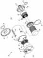
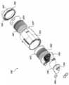
도 2는 도 1a의 필터 카트리지 어셈블리의 분해사시도이다;
도 3a 및 3b는 도 1a의 필터 카트리지 어셈블리의 측면도 및 단면도로서 필터하우징의 제1유동통로를 보여준다;
도 4a 및 도 4b는 도 1a의 필터 카트리지 어셈블리의 측면도 및 단면도로서 필터하우징의 제2유동통로를 보여준다;
도 5a 및 도 5b는 도 1a의 필터 카트리지 어셈블리의 측면도 및 단면도로서 필터하우징의 제3유동통로를 보여준다;
도 6은 도 1a의 필터 카트리지 어셈블리의 인접단부의 측면도로서, 단부 캡, 디스크 필터가 제거되며, 유동 통로가 노출된다;
도 7은 도 1a의 필터 카트리지 어셈블리의 인접단부의 측면도로서, 단부 캡, 디스크 필터 및 디스크 홀더가 제거되며, 유동 통로가 노출된다;
도 8a는 도 1a의 필터 카트리지 어셈블리의 부분 단면도로서, 인접단부 캡이 제거되고 제3유동통로를 도시한다;
도 8b는 도 8a의 L-L 라인을 따라 취한 도 1a의 필터 카트리지의 단면도이다;
도 8c는 도 8a의 P-P 라인을 따라 취한 도 1a의 필터 카트리지의 단면도이다;
도 9a는 본 발명의 제2바람직한 구현예에 따라 구성된 필터 카트리지 어셈블리의 측면도;
도 9b는 도 9a의 필터 카트리지 어셈블리의 인접단부의 측면도이다.
도 9c는 도 9a의 필터 카트리지 어셈블리의 사시도이다;
도 10은 각 부품의 설명을 위해 도 9a의 필터 카트리지 어셈블리의 분해사시도이다;
도 11은 도 9a의 필터 카트리지 어셈블리의 단면도로서, 필터하우징을 통해 제1유동통로를 보여준다;
도 12a는 도 9a의 필터 카트리지 어셈블리의 인접단부의 측면도이다;
도 12b는 도 9a의 필터 카트리지 어셈블리의 단면도로서, 필터하우징을 통해 제3유동통로를 보여준다;
도 13a는 본 발명의 구현예에 따라 구성된 3중 유동 여과 장치의 사시도로서, 컨트롤러/흡입기 모듈 및 필터 카트리지 어셈블리를 포함한다;
도 13b는 도 13a의 3중 여과 장치의 정면도이다;
도 14는 도 13a 및 도 13b의 3중 여과 장치을 이용하도록 구성된 소켓 어셈블리의 사시도이다.
도 15는 필터 카트리지 어셈블리의 사시도로서, 본 발명의 일 구현예에 따라 구성되고, 도 14의 소켓에 부분적으로 삽입된 상태를 보여준다;
도 16은 필터 카트리지 어셈블이의 사시도로서, 본 발명의 일 구현예에 따라 구성되고, 도 14의 소켓 어셈블리에 완전히 삽입된 상태를 보여준다;
도 17은 도 14의 소켓 어셈블리에 완전히 삽입된 필터 카트리지 어셈블리의 단면도이다.
도 18은 도 14의 소켓 어셈블리에 완전히 삽입된 필터 카트리지 어셈블리의 단면도로서, 소켓 어셈블리와 필터 카트리지 어셈블리 사이에 연통된 모습을 보여준다;
도 19는 본 발명의 다른 구현예에 따른 구성된 필터 카트리지 어셈블리의 앞쪽 상부에서 본 사시도이다;
도 20은 도 19의 필터 카트리지 어셈블리의 뒤쪽 상부에서 본 사시도이다;
도 21은 도 19의 필터 카트리지 어셈블리의 오른쪽 측면도이다;
도 22는 도 19의 필터 카트리지 어셈블리의 평면도이다;
도 23은 도 19의 필터 카트리지 어셈블리의 정면도이다;
도 24는 도 19의 필터 카트리지 어셈블리의 저면도이다;
도 25는 도 19의 필터 카트리지 어셈블리의 왼쪽 측면도이다;
도 26은 도 19의 필터 카트리지 어셈블리의 앞쪽 상부에서 본 분해사시도이다;
도 27은 도 19의 필터 카트리지 어셈블리의 뒤쪽 상부에서 본 분해사시도이다;
도 28은 본 발명의 일 구현예에 따라 구성된 3중 여과 장치의 사시도로서, 컨트롤러/흡입모듈 및 필터 카트리지 어셈블리를 포함한다;
도 29는 도 28의 3중 여과 장치의 정면도이다;
도 30은 일체형 튜브 세트를 가지는 필터 카트리지 어셈블리의 앞쪽 상부에서 본 사시도이다;
도 31은 분리형 튜브 세트를 이용하기 위한 커넥터를 가지는 도 19의 필터 카트리지 어셈블리의 앞쪽 상부에서 본 사시도이다;
도 32는 분리형 튜브 세트를 이용하기 위한 커넥터를 가지는 도 19의 필터 카트리지 어셈블리의 상세한 사시도로서, 연결 부싱을 도시한다.
도 33은 도 32의 부싱의 정면도이다; 및
도 34는 도 32의 부싱의 저면 사시도이다.
본 발명에 따라 구성된 필터 카트리지 어셈블리와 여과 장치의 이점은 첨부 도면을 참조하여 다음의 상세한 설명과 예시적인 구현예로부터 당해 기술분야에서 통상의 지식을 가진자에게 쉽게 이해될 것이지만, 본 발명의 범위를 제한하지 않는 것으로 의도된다.DETAILED DESCRIPTION OF THE PREFERRED EMBODIMENTS Reference will now be made in detail to embodiments of the present invention, examples of which are illustrated in the accompanying drawings, wherein like reference numerals refer to the like elements throughout.
IA is a front view of a filter cartridge assembly constructed in accordance with an embodiment of the present invention;
1B is a side view of the proximal end of the filter cartridge assembly of FIG. 1A;
Figure 2 is an exploded perspective view of the filter cartridge assembly of Figure la;
Figures 3a and 3b show a side view and a cross-sectional view of the filter cartridge assembly of Figure 1a, showing a first flow passage of the filter housing;
Figures 4A and 4B show a side view and a cross-sectional view of the filter cartridge assembly of Figure 1A, showing the second flow passage of the filter housing;
Figures 5A and 5B are side and cross-sectional views of the filter cartridge assembly of Figure 1A showing a third flow passage of the filter housing;
FIG. 6 is a side view of the proximal end of the filter cartridge assembly of FIG. 1A, with the end cap, disk filter removed, and the flow passages exposed;
FIG. 7 is a side view of the proximal end of the filter cartridge assembly of FIG. 1A, with the end cap, disc filter, and disc holder removed and the flow passages exposed;
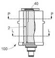
8A is a partial cross-sectional view of the filter cartridge assembly of FIG. 1A, with the adjacent end cap removed and showing a third flow passage;
FIG. 8B is a cross-sectional view of the filter cartridge of FIG. 1A taken along the line LL of FIG. 8A; FIG.
8C is a cross-sectional view of the filter cartridge of FIG. 1A taken along the line PP of FIG. 8A; FIG.
Figure 9a is a side view of a filter cartridge assembly constructed in accordance with a second preferred embodiment of the present invention;
Figure 9b is a side view of the proximal end of the filter cartridge assembly of Figure 9a.
Figure 9c is a perspective view of the filter cartridge assembly of Figure 9a;
10 is an exploded perspective view of the filter cartridge assembly of FIG. 9A for explaining each component;
FIG. 11 is a cross-sectional view of the filter cartridge assembly of FIG. 9A showing a first flow passage through the filter housing; FIG.
Figure 12a is a side view of the proximal end of the filter cartridge assembly of Figure 9a;
Figure 12B is a cross-sectional view of the filter cartridge assembly of Figure 9A showing the third flow passage through the filter housing;
13A is a perspective view of a triple flow filtration device constructed in accordance with an embodiment of the present invention, including a controller / inhaler module and a filter cartridge assembly;
FIG. 13B is a front view of the triple filtration apparatus of FIG. 13A; FIG.
14 is a perspective view of a socket assembly configured to use the triple filtration apparatus of FIGS. 13A and 13B.
Figure 15 is a perspective view of a filter cartridge assembly, constructed in accordance with an embodiment of the present invention and partially inserted into the socket of Figure 14;
Figure 16 is a perspective view of a filter cartridge assembly, constructed in accordance with an embodiment of the present invention and fully inserted into the socket assembly of Figure 14;
Figure 17 is a cross-sectional view of the filter cartridge assembly fully inserted into the socket assembly of Figure 14;
Figure 18 is a cross-sectional view of the filter cartridge assembly fully inserted into the socket assembly of Figure 14, showing the communication between the socket assembly and the filter cartridge assembly;
Figure 19 is a perspective view from a front upper side of a configured filter cartridge assembly according to another embodiment of the present invention;
Figure 20 is a perspective view from the rear upper portion of the filter cartridge assembly of Figure 19;
Figure 21 is a right side view of the filter cartridge assembly of Figure 19;
Figure 22 is a top view of the filter cartridge assembly of Figure 19;
Figure 23 is a front view of the filter cartridge assembly of Figure 19;
Figure 24 is a bottom view of the filter cartridge assembly of Figure 19;
Figure 25 is a left side view of the filter cartridge assembly of Figure 19;
Figure 26 is an exploded perspective view from the front upper side of the filter cartridge assembly of Figure 19;
Figure 27 is an exploded perspective view from the rear upper portion of the filter cartridge assembly of Figure 19;
28 is a perspective view of a triple filtration arrangement constructed in accordance with an embodiment of the present invention, including a controller / suction module and a filter cartridge assembly;
Fig. 29 is a front view of the triple filtration apparatus of Fig. 28; Fig.
30 is a perspective view from the front upper side of a filter cartridge assembly having an integral tube set;
Figure 31 is a perspective view from the front upper side of the filter cartridge assembly of Figure 19 with a connector for using a detachable tube set;
32 is a detailed perspective view of the filter cartridge assembly of FIG. 19 having a connector for using a detachable tube set, showing the connection bushing.
33 is a front view of the bushing of Fig. 32; And
34 is a bottom perspective view of the bushing of Fig. 32;
The advantages of the filter cartridge assembly and filter arrangement constructed in accordance with the present invention will be readily apparent to those of ordinary skill in the art from the following detailed description and exemplary embodiments with reference to the accompanying drawings, But is not intended to be limiting.
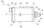
도면을 참조하면, 동일한 참조번호는 본 발명의 유사한 구조적인 요소를 지칭하고, 도 1a-8c에 본 발명의 바람직한 일 구현예에 따라 구성된 필터 카트리지가 도시되어 있고, 필터 카트리지는 일반적으로 참조번호 100에 의해 지시된다. 필터 카트리지(100)는 축방향으로 반대되는 인접단부(P)와 끝단부(D)를 가지며 길이가 긴 하우징(10)을 포함하고, 내부에 중공부를 가진다. 여기서 더욱 상세하게 설명되는 바와 같이 제1, 제2 및 제3유동 통로(25,35,45)는 각각 하우징의 인접 단부(P)에서 끝단부(D)로 연장된다. 유동 통로는 도 3b, 4b, 5b 및 8a-8c에서 유동 화살표로 도시되어 있다.Referring now to the drawings, wherein like reference numerals refer to like structural elements of the present invention, there is shown a filter cartridge constructed in accordance with one preferred embodiment of the present invention in Figures 1A-8C, Lt; / RTI > The
필터 카트리지(100)의 중공부 내측에 제1, 제2 및 제3필터엘리먼트(20,30,40)가 각각 배치되어 있다. 제1필터엘리먼트(20)는 제1입구포트(27)(도 3a 및 3b에서 흡입연결슬롯으로 간주됨)에서 제1출구포트(29)(도 3b에서 흡입/리턴 연결포트로 간주됨)까지의 제1유동통로(25)를 횡단하는 유체를 정화시킨다. 제2필터엘리먼트(20)는 제2입구포트(37)(도 4b의 재순환 여과 펌프에서 압력연결포트로 간주됨)에서 제2출구포트(39)(도 4a에서 압력연결포트로 간주됨)까지의 제2유동통로(35)를 횡단하는 유체를 정화시킨다. 최근에, 제3필터엘리먼트는 제3입구포트(47)(도 5b의 재순환 여과 펌프에서 감지/흡입 연결포트로 간주됨)에서 제3출구포트(49)(도 5a에서 감지/흡입 연결포트로 간주됨)까지의 제3유동통로(45)를 횡단하는 유체를 정화시킨다. 도 3b, 4b 및 5b에 가장 잘 보여지는 바와 같이 제1유동통로(25)는 제2 및 제3유동통로(35,45)와 각각 별개로 형성되고, 제2유동통로(35)는 제3유동통로(45)와 분리되어 있다.First, second and
도 2 및 3b에 도시한 바와 같이, 제1필터엘리먼트(20)는 방사방향으로 주름진 필터이다. 유체는 제1필터엘리먼트(20)를 통해 내측 방사방향으로 횡단함으로써 제1유동통로(25)에서 정화된다. 도 2 및 4b에 도시한 바와 같이, 제2필터엘리먼트(30)는 또한 방상방향으로 주름진 필터이고, 유체는 제2필터엘리먼트(30)를 통해 내측 방사방향으로 횡단함으로써 제2유동통로(35)에서 정화된다. 최근 도 2 및 도 5a에 도시한 바와 같이 제3필터엘리먼트(40)는 디스크 필터이고, 유체는 제3필터엘리먼트(40)를 통해 축방향으로/인접방향으로 횡단함으로써 제2유동통로(45)에서 정화된다.As shown in Figures 2 and 3b, the
도 2는 필터 카트리지(100)의 분해사시도를 제공한다. 도시한 바와 같이 필터 카트리지의 하우징(10)은 주요 몸체부(12), 인접단 캡(60) 및 끝단 캡(70)을 포함한다. 하우징(10)의 주요 몸체부(12)는 부분적으로 제1 및 제2필터엘리먼트(20,30)용 필터챔버를 가진다(도 3b 참조). 제1필터엘리먼트(20)는 주요 몸체부(12)에 삽입되고, 인접단부 벽(18)에 접촉한다. 내부 필터 지지구조(85)(도 2)는 제1필터엘리먼트(20)를 제1밀봉필터챔버(22)(도 3b 및 4b에서 흡입 필터 챔버와 동일함)의 내측에 끼워넣는다. 내부 필터지지구조(85)는 제1필터엘리먼트(20)와 인접한 제1구획요소(87)와, 구획요소(87)로부터 축방향으로 연장된 실린더 스템(89)을 포함한다. 오링(83)은 구획요소(87)에 형성된 원주홈에 위치하여 제1필터챔버(22)와 제2필터챔버(32)를 유체적으로 격리시키는 것을 보조한다.Fig. 2 provides an exploded perspective view of the
제2필터엘리먼트(30)는 필터지지구조(85)의 실린더 스템(89) 위에 위치하고, 제2구획요소(90)는 제2필터챔버(32)의 끝단부를 밀봉하기 위해 사용된다(도 3b 및 3a에서 압력 필터 챔버와 동일함). 제2구획요소(90)는 필터지지구조(85)의 실린더 스템(89)이 삽입되는 실린더 네크(neck)부(92)를 가진다.The
제3필터엘리먼트(40)는 하우징(10)의 내측에 디스크 홀더(80)에 의해 지지된다. 제3필터엘리먼트(40)와 디스크 홀더(80)는 인접단부 캡(60)과 하우징(10)의 주요 몸체부(12)의 인접단부 벽(18) 사이에 위치한다.The
도 3b, 4b 및 5b에 가장 잘 보인 바와 같이, 하우징(10)의 주요 몸체부(12)는 동심원상으로 위치한 원형 벽(외부(14) 및 내부(16))을 포함하고, 원형 벽은 인접단부 벽(18)과 일체로 형성된다. 이 도면에 도시한 바와 같이 상세하게 설명하면, 제2 및 제3유동통로부(35,45)는 하우징(10)의 원형 벽 사이에 형성된 통로에 연장된다.As best seen in Figures 3b, 4b and 5b, the
도 2,3a,4a 및 5a를 다시 참조하면, 하우징(10)의 인접단부(P)는 커넥터 요소(50)를 포함한다. 커넥터 요소(50)는 제1입구포트(27)와 제2 및 제3출구포트(39,49)를 각각 수용한다. 커넥터 요소(50)는 또한 루어 록 피팅(luer lock fitting)과 유사한 수나사산(52)을 포함하고, 수나사산에 의해 필터 카트리지(100)가 예를 들면 한쌍의 커넥터 헤드를 가지는 튜브셋(tube set)과 유체적으로 연결된다. 도 3b, 4b, 5b에 가장 잘 보인 바와 같이, 제1출구포트(29), 제2입구포트(37) 및 제3입구포트(47)는 하우징(10)의 끝단부(D)에서 동축상으로 배치된다.Referring again to Figures 2,3a, 4a and 5a, the proximal end P of the
도 3a 및 3b에 가장 잘 보인 바와 같이, 제1유동통로(25)는 하우징(10)의 주요 몸체부(12)의 인접단부 벽(18)에 형성된 구멍(4)(도 6 및 7 참조)를 통해 제1입구포트(27)와 커넥터 요소(50)에 형성된 슬롯홀에서 제1필터챔버(22)로 연장된다. 제1유동통로(25)의 유체는 제1필터엘리먼트(20)의 둘레 주위에 분산되고, 필터엘리먼트의 중심 코어의 필터매개체를 통해 내측 방사방향(도 8c 참조)으로 지나감으로써 정화된다. 그리고나서, 정화된 유체는 제1필터엘리먼트(20)의 중심코어에서 필터지지구조(85)의 실린더 스템(89)에 형성된 보어로 멀어지게 이동하여 제1출구포트(29)를 통해 필터하우징(10)을 빠져나온다.3a and 3b the
도 4a 및 4b에 가장 잘 보인 바와 같이, 실린더 스템이 제2필터엘리먼트(30)의 중심코어에 도달할 때까지 제2유동통로(35)는 필터지지구조(85)의 실린더 스템(89)의 외주면과 제2구획요소(90)의 실린더 네크(92) 사이에 형성된 제2입구포트(37)에서 연장된다. 그리고나서, 제2유동통로의 유체는 제2필터엘리먼트(30)(도 8b)의 필터 매개체를 통해 외측 방사방향으로 이동함으로써 정화되고, 정화된 유체는 하우징(10)의 주요 몸체부(12)의 외측 원형 벽(14)과 내측 원형 벽(16) 사이에 형성된 축방향 유동통로(6)로 제공된다. 축방향 유동 통로(6)는 또한 도 8b에 도시되고, 압력 필터 통로 스루(thru) 필터 하우징으로 간주된다. 축방향 유동통로(6)에서 정화된 유체는 원형단 벽(18)에 형성된 유동구멍(8)을 통해 하우징(10)의 주요 몸체부(12)에서 배출되고, 커넥터(50)에 형성된 제2출구포트(39)를 통해 필터 카트리지(100)의 인접단부(P)에서 배출된다.As best seen in Figures 4a and 4b, the
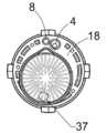
도 5a 및 5b에 가장 잘 보인 바와 같이, 제3유동통로(45)는 초기에 제3입구포트(47)로부터 축방향으로 연장되고, 제3입구포트는 제2구획요소(90)의 실린더 네크(92)의 외주면과 단부 캡(70)의 실린더 네크(72) 사이에 형성되고, 평면 챔버는 단부 캡(70)과 제2구획요소(90) 사이에 형성된다. 이 챔버로부터 제3유동통로(45)는 하우징(10)의 주요 몸체부(12)의 내측(16) 및 외측(14) 원형 벽 사이에 형성된 제2축방향 유동통로(2)로 외측 방사방향으로 이동한다. 이러한 축방향 유동통로(2)는 도 8b 및 8c(감지/흡입 필터 통과 스루 필터 하우징으로 간주됨)에 도시된다. 제2축방향 유동통로(2)의 유체는 원형단 벽(18)을 통해 하우징의 주요 몸체부에서 배출되고, 삼각형 형상의 챔버(24)(도 7 참조)에 공급된다. 이 챔버(24)로부터 제3유동통로(45)는 디스크 홀더(80)에 형성된 구멍(37)을 통해 그리고 제3필터엘리먼트(40), 디스크 필터를 통해 이동한다.5A and 5B, the
도 9a-12b를 참조하면, 본 발명의 바람직한 다른 구현예에 따른 필터 카트리지를 도시하고, 참조부호 200에 의해 지시된다. 필터 카트리지(200)는 축방향으로 반대되는 인접(P) 및 끝단부(D)와 중공부를 가지며 길이가 긴 하우징(110)을 포함한다. 이하에서 더욱 상세하게 설명하면, 제1, 제2 및 제3유동통로(125,135,145)는 각각 하우징의 인접단부(P)에서 끝단부(D)까지 연장된다. 유동통로는 도 11, 12a 및 12b에서 유동 화살표로 도시된다.Referring to Figures 9A-12B, there is shown a filter cartridge according to another preferred embodiment of the present invention, The
제1,제2 및 제3필터엘리먼트(120,130,140)는 각각 필터 카트리지(200)의 중공부 내측에 배치된다. 제1필터엘리먼트(120)는 제1입구포트(127)(도 11에서 흡입연결슬롯으로 간주됨)에서 제1출구포트(129)까지의 제1유동통로(125)를 횡단하는 유체를 정화시킨다. 제2필터엘리먼트(130)는 제2입구포트(137)에서 제2출구포트(139)(도 12b에서 압력가스출구로 간주됨)까지의 제2유동통로(135)를 횡단하는 유체를 정화시킨다. 최근에 제3필터엘리먼트(140)는 제3입구포트(147)로부터 제3출구포트(149)(도 12b에서 흡입가스출구로 간주됨)까지의 제3유동통로(145)를 횡단하는 유체를 정화시킨다. 도 11, 12a 및 12b에 가장 잘 보인 바와 같이 제1유동통로(125)는 제2 및 제3유동통로(135,145)로부터 각각 격리되고, 제2유동통로(135)는 제3유동통로(145)로부터 격리된다.The first, second, and
도 10 및 11에 도시한 바와 같이, 제1필터엘리먼트(120)는 방사방향으로 주름진 필터이다. 유체는 제1유동통로(125)에서 제1필터엘리먼트(120)를 통해 내측 방사방향으로 이동함으로써 정화된다. 도 10 및 12b에 도시한 바와 같이, 제2필터엘리먼트(130)는 방사방향으로 주름진 필터이고, 유체는 제2유동통로(135)에서 제2필터엘리먼트(130)를 통해 외측 방사방향으로 이동함으로써 정화된다. 최근에 도 10 및 12b에 도시한 바와 같이, 제3필터엘리먼트(140)는 디스크 필터이고, 유체는 제3유동통로(145)에서 축방향/인접방향으로 제3필터엘리먼트(140)를 통해 이동함으로써 정화된다.As shown in Figures 10 and 11, the
도 10을 참조하면, 필터 카트리지(200)의 분해사시도를 보여준다. 도시한 바와 같이, 필터 카트리지(200)의 하우징(110)은 외부몸체부(112)와 인접단부 캡(160)을 포함한다. 이중 벽 하우징(10)과 끝단부 캡(70)을 이용하는 필터 카트리지(100)와 달리 카트리지(200)의 하우징(110)은 단일 벽 외부몸체부(112)를 가지고, 제1 및 제2내부챔버부(154,156)를 포함한다. 하우징(110)의 제1 및 제2내부챔버부(154,156)는 부분적으로 제1 및 제2필터엘리먼트(120/130)의 필터챔버를 형성한다.10, an exploded perspective view of the
제2내부챔버부(156)는 외부몸체부의 끝단에 형성된 구멍을 통해 연장될 때까지 하우징(110)의 외부몸체부(112)의 인접단부(P)로 삽입되는 실린더 네크부(192)를 포함한다. 제2필터엘리먼트(130)는 제2내부챔버부에 배치되고, 제2필터챔버(132)는 제1내부챔버부(154)와 일체로 형성된 실린더 스템(189)을 제2필터엘리먼트(130)의 중심을 통해 실린더 네크부(192)의 보어로 삽입함으로써 안정적으로 장착된다. 제1필터엘리먼트(120)는 제1내부챔버부(154)에 형성된 중공부의 내측에 포함되고, 제1필터챔버(122)는 디스크 홀더(도 10 참조)와 인접단부 캡(160)을 이용하여 외부몸체부(112)의 인접단을 밀봉함으로써 안정적으로 장착된다. 제3필터엘리먼트(140)는 디스크 홀더(150)를 이용하여 하우징(112)에 지지되고, 디스크 홀더(150)는 상부 절반부(150a)와 하부 절반부(150b)를 포함한다.The second
도 9c에 가장 잘 보이는 바와 같이, 하우징(110)의 외부몸체부는 약 90도 각도로 이격된 두개의 길이방향 리브(150a/15b)를 포함한다. 리브는 외부몸체부(112)의 내벽과 제1 및 제 2내부챔버부(154/156) 사이에 길이방향의 채널 또는 통로를 마련하기 위해 이용된다. 도면에 도시한 바와 같이 이하에서 상세하게 설명하기로 하면, 제2 및 제3유동통로(135,145)의 일부는 내부챔버부와 하우징의 외부몸체부 사이에 형성된 길이방향의 채널에 연장된다.As best seen in Figure 9c, the outer body portion of the
도 9a, 9b, 11, 12a 및 12b을 참조하면, 하우징(110)의 인접단(P)은 커넥터 요소(150)를 포함한다. 커넥터 요소(150)는 제1입구포트(127)와 제2 및 제3입구포트(139,149)를 각각 포함한다. 커넥터 요소(150)는 또한 루어 록 피팅(lure lock fitting)과 같은 수나사산(152)을 포함하고, 이 커넥터 요소는 필터 카트리지(200)를 예를 들면 한쌍의 커넥터 헤드를 가지는 튜브 셋와 유체적으로 결합되게 한다. 도 9a, 11 및12b에 가장 잘 보이는 바와 같이 제1출구포트(129), 제2입구포트(137)와 제3입구포트(147)는 하우징(110)의 끝단에 동축상으로 배치된다.Referring to Figures 9a, 9b, 11, 12a and 12b, a proximal end P of the
도 11에 가장 잘 보인 바와 같이, 제1유동통로(125)는 커넥터 요소(150)에 형성된 슬롯홀에 위치하는 제1입구포트(127)로부터, 상부 및 하부 디스크 홀더 절반부(150a/150b)에 형성된 통로(104)를 통해 제1필터챔버(122)로 연장된다. 제1유동통로(125)에 흐르는 유체는 제1필터엘리먼트(120)의 둘레 주변에 분포되고, 필터 매개체를 통해 내측 방사방향(도 11 참조)으로 제1필터엘리먼트(120)의 중심보어로 통과시킴으로써 정화된다. 정화된 유체는 그리고 나서 제1필터엘리먼트(120)의 중심보어에서 멀어지게 제1내부챔버부(154)의 실린더 스템(189)에 형성된 보어로 이동하고, 제1출구포트(129)를 통해 필터하우징에서 배출된다(도 11).11, the
도 12a 및 12b에 가장 잘 보인 바와 같이, 제2내부챔버부(156)가 제2필터엘리먼트(130)의 중심 코어에 도달할 때까지 제2유동통로(135)는 제1내부챔버부(154)의 실린더 스템(189)의 외부 둘레와 제2내부챔버부(156)의 실린더 네크(192) 사이에 형성된 제2입구포트(137)에서 연장된다. 제2유동통로(135)에 흐르는 유체는 제2필터엘리먼트(130)의 필터매개체를 통해 내측 방사방향으로 이동함으로써 정화되고, 정화된 유체는 제2내부챔버부(156)에 형성된 측면 구멍(102;도 10 참조)을 통해 외부 주요 몸체부(112)의 리브(158b)와 제1 및 제2챔버부(154/156)의 외측 둘레벽 사이에 형성된 축방향 유동통로(106)로 공급된다. 축방향 유동통로(106)에 흐르는 정화된 유체는 인접단부 캡(160)에 형성된 방사방향으로 향한 채널(197;도 12a 참조)로 이동되고, 커넥터(150)에 형성된 제2출구포트(139)를 통해 제2필터 카트리지(200)의 인접단부(P)에서 배출된다.As best seen in Figures 12a and 12b, the
도 12a 및 12b에 가장 잘 도시한 바와 같이, 제3유동통로(145)는 초기에 제3입구포트(147)로부터 축방향으로 연장되고, 제3입구포트는 제2내부챔버부(156)의 실린더 네크(192)의 외부 둘레와 하우징(110)의 외부몸체부(112)의 실린더 네크(172) 사이에서, 리브(158a)와 제2내부챔버부(156)의 외표면 사이에 형성된 방사방향의 채널로 형성된다. 제3유동통로(145)에 흐르는 유체는 외부 몸체부의 리브(158a)와 제1 및 제2내부챔버부(154/156;도 10)의 외측 둘레벽 사이에 형성된 제2축방향 유동통로(126)에 공급된다. 축방향 유동통로(126)에 흐르는 유체는 측면 구멍(172;도 10 참조)을 통해 상부 및 하부 디스크 홀더 절반부(150a/150b)에 의해 정의된 제3필터챔버(142)로 향한다. 제3필터챔버(142)에 흐르는 유체는 제3필터엘리먼트(140), 디스크 필터를 통해 축방향으로 통과시킴으로써 정화된다. 정화된 유체는 인접단부 캡(160)의 하측에 형성된 웨지모양의 챔버(124;도 12a)에 공급되고, 커넥터(150)에 형성된 제3출구포트(149)를 통해 하우징(110)에서 배출된다.12A and 12B, the
당해기술분야에서 숙련된 자는 본 발명이 특정한 필터 종류 또는 매개체, 예를 들면 방사방향으로 주름진 필터엘리먼트에 한정되지 않는 것으로 인식할 것이다. 예를 들면 수지로 접착된 셀룰로오스 타입의 필터, 박테리아와 같은 병원성 미생물를 여과시키기 위한 섬유성 매개체, 카본 블록 필터 매개체, 나선형으로 감긴 매개체 등이 사용될 수 있다.Those skilled in the art will recognize that the invention is not limited to any particular filter type or medium, for example, a radially corrugated filter element. For example, a cellulose type filter bonded with a resin, a fibrous medium for filtering pathogenic microorganisms such as bacteria, a carbon block filter medium, a spiral wound medium, and the like can be used.
도 13a-17을 참조하면, 본 발명의 바람직한 구현예에 따른 구성되며 일반적으로 참조번호 300에 의해 지시되는 여과 장치(300)가 도시되어 있다. 여기서 설명되는 바와 같이 여과 장치는 3개의 분리된 유체소스로부터 받은 유체를 정화하고, 미국특허출원번호 11/960,701호 및 국제특허출원공개번호 WO2008/077080에 개시되고, 2008년 6월 26일에 공개된 외과용 투관침과 관련하여 이용하도록 구성되고, 이 특허문헌의 전문내용은 참고문헌으로 사용된다.Referring now to Figures 13A-17, there is shown a
여과 장치(300)는 다른 요소 사이에, 컨트롤러(310), 소켓 어셈블리(330) 및 이전에 설명된 필터 카트리지 어셈블리(100)를 포함한다. 이하에서 상세하게 설명되는 바와 같이, 컨트롤러(310)는 여과 장치(300)에서 유체의 흐름을 조절 및 모니터링하기 위한 메카니즘을 포함한다.The
컨트롤러(310)는 평면의 상부 및 하부면(314,316), 및 곡선의 측벽(318a/318b)을 각각 가지는 외부하우징(312)을 포함한다. 측벽(318a/318b)은 컨트롤러(310)를 이동시키거나 조작하기 위한 손잡이용 리세스(320a;반대쪽 측면, 미도시)/(320b)를 포함한다. 평면의 하부면(316)은 컨트롤러(310)를 유틸리티 카트에 배치되게 하거나 붐(BOOM) 메카니즘을 이용하여 수술실의 천정 위에서부터 지지되게 한다.The
컨트롤러(310)의 앞쪽면(322)은 아날로그 게이지(324), 다이얼(326), 전원버튼(328) 및 잭(329)을 포함한다. 이러한 요소들의 목적 및 작용을 이하에서 설명하기로 한다. 길이가 긴 리셉터클(340) 또는 보어는 컨트롤러(310)용 하우징(312)에 형성되고, 컨트롤러(310)의 앞쪽면(322)에서 컨트롤러(310)로 연장된다. 리셉터클(340)은 소켓 어셈블리(330)를 수용하도록 구성된다(도 14-17 참조). 당해기술분야에서 숙련된 자는 아날로그 게이지보다 오히려 디지털 게이지가 사용될 수 있고, 컨트롤러에 추가 다이얼, 게이지, 판독기가 장착될 수 있음을 쉽게 인식할 것이다.The
도 14-17을 참조하면, 소켓 어셈블리(330)는 컨트롤러(310)와 연통가능하고 필터 카트리지(100)를 탈착가능하게 유지하도록 어댑터 기능을 수행한다. 소켓 어셈블리(330)는 필터 카트리지 어셈블리(100)가 삽입되는 중심 보어(334)를 가지는 주요 몸체부(332)를 포함한다. 록킹 요소(336)와 마운팅 링(338)은 소켓 어셈블리(330)의 인접 단부에 위치한다. 마운팅 링(338)은 소켓 어셈블리(330)를 컨트롤러(310)에 고정하기 위해 그 둘레면에 복수의 홀을 가진다.14-17, the
소켓 어셈블리(330)의 록킹 요소(336)는 외측 둘레부에서 외측 방사방향으로 연장된 레버 암(344)을 가지는 캠 링(342;CAM RING)을 구비하는 캠 메카니즘을 포함한다. 레버 암(344)은 소켓 어셈블리(330)의 주요 몸체부(332)에 대하여 캠 링(342)을 회전시키는데 사용된다. 캠 링(342)은 한쪽으로 경사진 캐밍(CAMMING) 채널(348;도 14에 2개가 도시됨)에 각각 끝나는 4개의 축방향 슬롯(346)을 포함한다.The locking
도 2에 도시한 바와 같이, 필터 카트리지 어셈블리(100)의 하우징(10)의 주요 몸체부(12)는 그 외측 둘레면에 4개의 방사방향으로 이격된 돌기부(62)와 정렬 리브(64)를 가진다. 당해기술분야에서 숙련된 자는 본 발명이 어떤 특정한 수 또는 방향의 캠 돌기부에 한정되지 않는 것을 쉽게 인식할 것이다.The
도 15에 도시한 바와 같이, 필터 카트리지 어셈블리(100)는 소켓 어셈블리(330)의 중심 보어(334)에 삽입될 때 각 정렬 리브(64)는 소켓 어셈블리(330)의 주요 몸체부(332)에 형성된 각각의 쌍으로 된 채널(350;외측면에서 돌출되는)에 수용될 수 있도록 배향되어야 한다(도 15 참조). 더우기, 캐밍 돌기부(62)는 캠 링(342)의 축방향 슬롯(346)과 경사진(PITCHED) 캐밍 채널(348)을 통해 지나간다. 캠 링(342)이 필터 카트리지 어셈블리(100)에 대하여 회전될 때 도 13a 및 13b에 도시한 바와 같이 회전시킴으로써(방향 화살표 352 도시), 하우징(12)의 외측 둘레면에 형성된 캐밍 돌기부(62)가 경사진 캐밍 채널(348)에 걸리고, 필터 카트리지 어셈블리(100)는 소켓 어셈블리(330)의 중심 보어(334)로 더욱 꽉 끼워지게 되어 컨트롤러(310)와 연통되게 고정된다(도 16 및 17).15, when the
도 18에 도시한 바와 같이 제1유동통로(100)에 흐르는 유체는 중심축을 따라 필터 어셈블리(100)에서 배출되고, 소켓 어셈블리(330)에 형성된 축방향 포트를 통해 지나간다. 유체는 소켓 어셈블리(330)에 형성된 방사방향의 포트를 통해 필터어셈블리의 제2 및 제3유동통로에 공급된다.The fluid flowing in the
작동되는 컨트롤러(310)는 흡입유닛을 포함하고, 미국특허출원 11/960,701 및 국제특허출원공개번호 WO 2008/077080에 개시되고 2008년 6월 26일에 공개된 것과 유사한 외과용 투관침(TROCAR)에 연결될 수 있다. 트로카는 유체도관 또는 튜브 셋에 의해 컨트롤러에 연결될 수 있다. 여기서 개시된 구현예에서 컨트롤러는 흡입기를 포함하지 않고 잭(329)을 통해 흡입기로부터 발생된 흡입가스를 수용한다. 흡입기는 예를 들면 공급탱크로부터 가스를 받고, 압력 레귤레이터는 통상 탱크와 흡입기 사이에 제공된다.The actuated
컨트롤러의 작용은 미국특허출원 11/960,701 및 2008년 6월 26일에 공개된 국제특허출원공개번호 WO 2008/077080에 상세하게 설명되기 때문에 여기서 반복하지 않기로 한다. 이러한 참고문헌에 언급된 바와 같이, 여기에 개시된 외과용 흡입 및 재순환 장치는 3개의 분리된 유체 소스의 필터링을 요구한다. 컨트롤러(310)는 이 출원에서 설명된 장치의 구현예를 이용할 수 있다. 도 13a 및 13b에 도시한 바와 같이 컨트롤러(310)는 컨트롤러로부터 원하는 압력 출력을 설정하기 위해 설정가능한 다이얼(326)과, 설정압력을 확인하기 위한 압력게이지(324)를 포함한다.The operation of the controller will not be repeated here as it is described in detail in U.S. Patent Application Serial No. 11 / 960,701 and International Patent Application Publication No. WO 2008/077080, published on June 26, 2008. As mentioned in these references, the surgical suction and recirculation apparatus disclosed herein requires filtering of three separate fluid sources.
설명한 바와 같이, 필터 카트리지 어셈블리(100)는 제어유닛(310)에 직접 장착될 수 있고, 측면 높이가 낮게 제공된다. 상기한 구성에서, 필터 카트리지 어셈블리(100)의 제1유동통로(25)는 복부 환자(흡입 라인)로부터 제거되는 가스를 여과시키거나 소비된 흡입 유체를 제거하기 위해 사용된다. 필터 카트리지 어셈블리(100)의 제2유동통로(35)는 투관침에 제공되는 압력가스를 조절하고, 투관침을 통해 기구 및 이와 유사한 것을 통과시키는데 사용되는 중공부를 밀봉하는데 사용된다. 필터 카트리지 어셈블리(100)의 제3유동통로(45)는 흡입 및 감지용 압력가스를 조절하는데 사용된다.As described, the
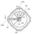
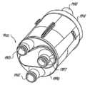
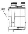
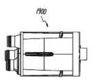
도 19-27은 본 발명의 다른 구현예에 따라 구성된 필터 카트리지 어셈블리(1900)를 도시한다. 전술한 구현예에서, 필터 카트리지 어셈블리는 복수의 유동통로를 여과시키기 위해 복수의 필터요소를 포함한다. 하우징(1920)의 형상에서 차이가 제공되고, 유동통로가 하우징 및 다른 특징요소의 내부에 형성된다. 그러나 필터(1900)와 함께 필터 카트리지(100)의 특징과 유사한 특징이 도시되어 있고 반드시 명확하게 설명되는 것은 아니다.19-27 illustrate a
도 19 및 20에 가장 잘 도시한 바와 같이, 필터 카트리지(1900)는 튜브 셋용 연결부(1950), 앞쪽 단부 캡(1910), 하우징(1920) 및 뒤쪽 단부 캡(1990)을 포함한다. 뒤쪽 단부 캡(1990)에는 재순한되기까지 연결을 위해 포트들이 형성되어 있다. 한 개의 포트(1953)는 필터 카트리지(1900)를 통해 유닛으로부터 압력을 공급하기 위한 것이고, 한 개의 포트(1953)는 필터 카트리지(1900)를 통해 흡입 및 압력 감지를 위한 것이고, 한 개의 포트(1955)는 카트리지로부터 유닛으로 리턴시키기 위한 것이다.19 and 20, the
도 26 및 27의 분해도에서 부품들을 보여주고, 부품의 기능을 설명하면 다음과 같다. 앞쪽 단부 캡(1910)은 캡에 있는 연결부(1950)로부터 유동을 분배한다. 재순환 유동은 튜브 셋으로부터 낮고 넓은 포트의 커넥터(1950)를 통해 앞쪽 판(1910)과 분리판(1973) 사이에 형성된 챔버로 이루어지고, 분리판은 유체를 정지시키는 것을 돕고 유체가 수평으로 주름지고 실린더 형상을 가진 재순환 필터(1981)에 도달하는 것을 방지한다. 필터(1981)는 실질적으로 삼각형 단면 형상을 가지는 테이퍼 링에 의해 하우징(1920)의 챔버(1922)의 저면과 차단되고, 테이퍼링의 작은 단부는 하우징(1920)의 중심 벽(1924)과 인접하게 된다. 리턴 플로우는 필터(1981)와 하우징의 채널(1926)을 통해, 뒤쪽 엔드플레이트(1990)의 또 다른 통로를 통해 및 각각의 포트(1955)를 통해 지나간다.Components in the exploded view of Figs. 26 and 27 are shown and the functions of the parts are described as follows. The
흡입 압력은 평면 필터(1985)를 통해 포트(1957)에서 리어 엔드플레이트(1990)에서 리어 하우징부(1995)에 형성되는 챔버로, 하우징(1920)에 형성된 채널(1921)로, 커넥터(1950)의 각 포트를 통해 앞쪽 단부 캡에 형성된 채널(1911)로 지나간다.The suction pressure is transmitted to the
유닛으로부터 발생된 압력은 포트(1953)를 통해 하우징(1995)과 엔드플레이트(1990)에 의해 압력필터(1983)용으로 형성된 리어 챔버로 흐른다. 링(1977)은 또한 분리벽(1924)으로부터 필터를 격리시키기 위해 제공된다. 채널(1929)은 하우징(1920)을 통해 압력을 앞쪽 단부 캡(1910)으로 전달하고, 앞쪽 단부 캡에서 채널(1919)은 커넥터(1950)를 통해 유체를 흐르게 한다.The pressure generated from the unit flows through the
필터(1983,1981)는 바람직하게는 하우징(1920)에 대하여 접착제로 밀봉된다. 그루부와 한쌍의 돌출부는 인접하는 하우징부 사이에 제공될 수 있고, 접착제에 의해 접착되거나 초음파 용접과 같은 다른 적절한 수단에 의해 부착될 수 있다.The filter (1983, 1981) is preferably sealed with an adhesive to the housing (1920). The grooves and the pair of protrusions may be provided between adjacent housing parts and may be adhered by an adhesive or by other suitable means such as ultrasonic welding.
도 28-29는 본 발명의 일 구현예에 따른 3개 유동의 여과 장치(2800)의 다른 구현예를 도시하고, 컨트롤러/흡입기 모듈 및 필터 카트리지 어셈블리(1900)를 포함한다. 장치(2800)는 디지털 판독기(2824)를 포함하지만, 도 13a 및 13b의 구현예와 비슷한 특징을 포함할 수 있다.28-29 illustrate another embodiment of a three-
도 30은 튜브 셋(3010)이 통합되고, 도 19의 필터 카트리지를 앞쪽 위에서 본 사시도이다. 부시(3090)는 튜브 셋(3010)의 3개 돌출 튜브를 필터 하우징(1900)에 연결하기 위해 제공된다. 연결부(3140)는 또 다르게 제공될 수 있다. 부시(3090)는 도 33 및 34에 도시한 바와 같이 실질적으로 튜브에 맞는 내부 홀(3093;contour)과, 연결부(1950)와 연결하기 위한 외측 테이퍼(3094)를 포함하고, 튜브 셋과 필터의 압축 피팅을 용이하게 한다. 접착제는 튜브 셋(3010)과 필터(1900) 사이의 밀봉을 용이하게 하기 위해 사용된다.
Figure 30 is a perspective view of the filter cartridge of Figure 19, viewed from the front, incorporating the
Claims (20)
Translated fromKoreanⅱ) 컨트롤러의 리셉터클의 내측에 적어도 부분적으로 위치하는 소켓 어셈블리;
ⅲ) 소켓 어셈블리에 삽입되고, 록킹 엘리먼트에 의해 컨트롤러와 연통되게 고정되는 필터 카트리지 어셈블리:를 포함하고, 세 개의 분리된 유체 소스로부터 받은 유체를 정화하며,
상기 필터 카트리지 어셈블리는 축방향으로 반대되는 인접단부와 끝단부를 가지며, 하우징의 인접단부에서 끝단부로 연장되는 중공부, 중심축, 제1 및 제2 및 제3유동통로를 가지는 하우징을 포함하고,
상기 필터 카트리지 어셈블리 하우징의 인접단부는 커넥터 요소를 포함하고,
상기 커넥터 요소는 제1유동통로와 연결되는 제1입구포트, 제2유동통로와 연결되는 제2출구포트 및 제3유동통로와 연결되는 제3출구포트를 포함하는 것을 특징으로 하는 여과 장치.
I) a controller having means for regulating and monitoring fluid flow in the filtration device, the receptacle having a receptacle;
Ii) a socket assembly located at least partially within the receptacle of the controller;
Iii) a filter cartridge assembly inserted into the socket assembly and secured in communication with the controller by a locking element, the filter cartridge assembly cleaning fluid received from three separate fluid sources,
The filter cartridge assembly comprising a housing having axially opposing proximal and distal ends and a hollow portion extending from a proximal end to a distal end of the housing, a central axis, a housing having first and second and third flow passages,
Wherein a proximal end of the filter cartridge assembly housing includes a connector element,
Wherein the connector element comprises a first inlet port connected to the first flow passage, a second outlet port connected to the second flow passage, and a third outlet port connected to the third flow passage.
The filtration device according to claim 1, wherein the outer circumferential portion of the locking element includes a cam mechanism for engaging protrusions extending from the outer surface of the filter cartridge assembly.
i) 제1유동통로를 따라 제1입구포트에서 제1출구포트로 이동하는 유체를 정화시키기 위해 하우징의 중공부 내부에 중심축을 따라 배치된 제1필터엘리먼트;
ⅱ) 제2유동통로를 따라 제2입구포트에서 제2출구포트로 이동하는 유체를 정화시키기 위해 하우징의 중공부 내부에 중심축을 따라 배치된 제2필터엘리먼트; 및
ⅲ) 제3유동통로를 따라 제3입구포트에서 제3출구포트로 이동하는 유체를 정화시키기 위해 하우징의 중공부 내부에 중심축을 따라 배치된 제3필터엘리먼트;를 포함하고, 제1유동통로는 제2 및 제3유동통로와 격리되고, 제2유동통로는 제3유동통로와 격리되는 것을 특징으로 하는 여과 장치.
The filter cartridge assembly of claim 1, wherein the filter cartridge assembly comprises:
i) a first filter element disposed along the central axis within the hollow of the housing for purifying fluid moving from the first inlet port to the first outlet port along the first flow path;
Ii) a second filter element disposed along the central axis within the hollow portion of the housing for purifying fluid moving from the second inlet port to the second outlet port along the second flow passage; And
And iii) a third filter element disposed along the central axis within the hollow portion of the housing for purifying fluid moving from the third inlet port to the third outlet port along the third flow passage, Second and third flow passages, and the second flow passage is isolated from the third flow passage.
The filtration device of claim 3, wherein the housing comprises a pair of coaxially positioned peripheral walls, the coaxially positioned pair of peripheral walls comprising at least one axial flow passage.
7. The filtration apparatus according to claim 6, characterized in that a part of each of the second and third flow passages divided by the axial inner wall and the outer wall is moved to each of the axial flow passages constituted by the peripheral wall of the housing .
4. The filtration device according to claim 3, wherein the first filter element is a radially corrugated filter and the fluid is purified in the first flow passage by moving in the inner radial direction through the first filter element.
The filtration device of claim 3, wherein the third filter element is a disk filter and the fluid is purged in the third flow passage by moving axially through the third filter element.
4. The filtering device according to claim 3, wherein the housing comprises a cylinder inner housing element located inside the hollow portion of the housing and has a first chamber for the first filter element.
12. The filtration device according to claim 11, wherein the housing further comprises a second inner housing element located inside the hollow of the housing and has a second chamber for the second filter element.
4. The apparatus of claim 3, wherein the housing comprises two longitudinal ribs having two longitudinal channels in an inner hollow portion of the housing, the second flow passage being movable to one of the channels, And the filter is moved.
4. The apparatus of claim 3, wherein the first outlet port connected to the first flow passage, the second inlet port connected to the second flow passage, and the third inlet port connected to the third flow passage are located at the end of the housing Filtration device.
Applications Claiming Priority (3)
| Application Number | Priority Date | Filing Date | Title |
|---|---|---|---|
| US19589808P | 2008-10-10 | 2008-10-10 | |
| US61/195,898 | 2008-10-10 | ||
| PCT/US2009/060298WO2010042914A2 (en) | 2008-10-10 | 2009-10-10 | Multi-flow filtration system |
Publications (2)
| Publication Number | Publication Date |
|---|---|
| KR20110084236A KR20110084236A (en) | 2011-07-21 |
| KR101680588B1true KR101680588B1 (en) | 2016-11-29 |
Family
ID=42101252
Family Applications (1)
| Application Number | Title | Priority Date | Filing Date |
|---|---|---|---|
| KR1020117010687AActiveKR101680588B1 (en) | 2008-10-10 | 2009-10-10 | Multi-flow filtration system |
Country Status (6)
| Country | Link |
|---|---|
| US (3) | US7976598B2 (en) |
| EP (1) | EP2364197B1 (en) |
| JP (1) | JP5654996B2 (en) |
| KR (1) | KR101680588B1 (en) |
| CN (1) | CN102264451B (en) |
| WO (1) | WO2010042914A2 (en) |
Families Citing this family (41)
| Publication number | Priority date | Publication date | Assignee | Title |
|---|---|---|---|---|
| US10973545B2 (en) | 2002-05-31 | 2021-04-13 | Teleflex Life Sciences Limited | Powered drivers, intraosseous devices and methods to access bone marrow |
| US20070049945A1 (en) | 2002-05-31 | 2007-03-01 | Miller Larry J | Apparatus and methods to install, support and/or monitor performance of intraosseous devices |
| US11337728B2 (en) | 2002-05-31 | 2022-05-24 | Teleflex Life Sciences Limited | Powered drivers, intraosseous devices and methods to access bone marrow |
| US8668698B2 (en) | 2002-05-31 | 2014-03-11 | Vidacare Corporation | Assembly for coupling powered driver with intraosseous device |
| EP2039298B1 (en) | 2002-05-31 | 2017-10-25 | Vidacare LLC | Apparatus to access bone marrow |
| US8641715B2 (en) | 2002-05-31 | 2014-02-04 | Vidacare Corporation | Manual intraosseous device |
| US9504477B2 (en) | 2003-05-30 | 2016-11-29 | Vidacare LLC | Powered driver |
| US8944069B2 (en) | 2006-09-12 | 2015-02-03 | Vidacare Corporation | Assemblies for coupling intraosseous (IO) devices to powered drivers |
| GB0803564D0 (en) | 2008-02-27 | 2008-04-02 | Smith & Nephew | Fluid collection |
| US8827983B2 (en) | 2008-08-21 | 2014-09-09 | Smith & Nephew, Inc. | Sensor with electrical contact protection for use in fluid collection canister and negative pressure wound therapy systems including same |
| WO2012044410A2 (en)* | 2010-09-20 | 2012-04-05 | Surgiquest, Inc. | Multi-flow filtration system |
| WO2012122263A2 (en) | 2011-03-08 | 2012-09-13 | Surgiquest, Inc. | Trocar assembly with pneumatic sealing |
| US8906143B2 (en)* | 2011-09-02 | 2014-12-09 | Membrane Technology And Research, Inc. | Membrane separation apparatus for fuel gas conditioning |
| US10004856B2 (en)* | 2011-12-01 | 2018-06-26 | Buffalo Filter Llc | Filtration system and method |
| WO2014081783A1 (en) | 2012-11-20 | 2014-05-30 | Surgiquest, Inc. | Systems and methods for conducting smoke evacuation during laparoscopic surgical procedures |
| WO2014100210A1 (en) | 2012-12-19 | 2014-06-26 | Surgiquest, Inc. | Coupling for connecting a tube set to a trocar |
| KR101448049B1 (en)* | 2013-08-20 | 2014-10-08 | 쿠쿠전자주식회사 | cover member interworking security water treatment apparatus |
| EP4424347A3 (en)* | 2014-05-15 | 2024-10-30 | Fisher & Paykel Healthcare Limited | Active smoke filtration for insufflation |
| CA3179001A1 (en) | 2014-07-31 | 2016-02-04 | Smith & Nephew, Inc. | Systems and methods for applying reduced pressure therapy |
| US12133789B2 (en) | 2014-07-31 | 2024-11-05 | Smith & Nephew, Inc. | Reduced pressure therapy apparatus construction and control |
| US9962520B2 (en) | 2014-10-15 | 2018-05-08 | Surgiquest, Inc. | Branching multi-lumen tube set for laparoscopic surgical procedures involving smoke evacuation |
| US9387295B1 (en)* | 2015-01-30 | 2016-07-12 | SurgiQues, Inc. | Filter cartridge with internal gaseous seal for multimodal surgical gas delivery system having a smoke evacuation mode |
| US10159809B2 (en) | 2015-01-30 | 2018-12-25 | Surgiquest, Inc. | Multipath filter assembly with integrated gaseous seal for multimodal surgical gas delivery system |
| US9387296B1 (en)* | 2015-01-30 | 2016-07-12 | Surgiquest, Inc. | Filter cartridge with integrated gaseous seal for multimodal surgical gas delivery system |
| WO2017003712A1 (en)* | 2015-06-30 | 2017-01-05 | Surgiquest, Inc. | Multipath filter assembly with integrated gaseous seal for multimodal surgical gas delivery system |
| CN105796163B (en)* | 2016-05-10 | 2019-01-25 | 安徽优尼科医疗科技有限公司 | A kind of laparoscope filtering puncture outfit |
| US10508572B2 (en)* | 2017-02-01 | 2019-12-17 | Joe Mainiero | Oil and air separator system adapter and method |
| US10869691B2 (en) | 2017-03-08 | 2020-12-22 | Conmed Corporation | Flexible single lumen gas sealed access port for use during robotically assisted endoscopic surgical procedures |
| US10806490B2 (en)* | 2017-03-08 | 2020-10-20 | Conmed Corporation | Single lumen gas sealed access port for use during endoscopic surgical procedures |
| WO2018195101A1 (en) | 2017-04-19 | 2018-10-25 | Smith & Nephew, Inc. | Negative pressure wound therapy canisters |
| US12337102B2 (en) | 2017-06-30 | 2025-06-24 | Conmed Corporation | Filter cartridge assemblies |
| US11185644B2 (en) | 2017-06-30 | 2021-11-30 | Conmed Corporation | Filter cartridge assemblies |
| US11458426B2 (en) | 2017-10-27 | 2022-10-04 | Cummins Filtration Ip, Inc. | Integrated module with stage one and stage two filters combined in single housing |
| CN111565770B (en)* | 2017-12-28 | 2023-10-10 | 爱惜康有限责任公司 | Dual series large droplet filter and small droplet filter |
| US10980549B2 (en) | 2018-02-14 | 2021-04-20 | DePuy Synthes Products, Inc. | Graft filter with locking graft filter element and graft extractor |
| CA3118299C (en) | 2018-10-29 | 2023-06-06 | Advanced Filtration Technology, Inc. | A system and method for fluid filtration |
| TWI699233B (en)* | 2019-09-12 | 2020-07-21 | 濾能股份有限公司 | A cylindric filter device, a manufacturing method and an usage of the same, and a filter system having the same |
| GB201914283D0 (en)* | 2019-10-03 | 2019-11-20 | Smith & Nephew | Apparatuses and methods for negative pressure wound therapy |
| CN112302802A (en)* | 2020-11-13 | 2021-02-02 | 无锡华南钢结构环保有限公司 | Particle air filtering mechanism capable of being replaced quickly for gas turbine |
| CN114191009B (en)* | 2021-12-15 | 2024-08-23 | 江苏人冠医疗科技有限公司 | Pipeline connection structure and endoscope smoke circulation system |
| CN114146507B (en)* | 2021-12-15 | 2023-07-07 | 江苏人冠医疗科技有限公司 | Filter equipment and chamber mirror smog circulation system |
Citations (3)
| Publication number | Priority date | Publication date | Assignee | Title |
|---|---|---|---|---|
| US3154487A (en) | 1962-11-16 | 1964-10-27 | Framo Corp | Dual fluid filters |
| JP2005523145A (en) | 2002-04-18 | 2005-08-04 | キュノ、インコーポレーテッド | Double flow filter cartridge |
| WO2008077080A2 (en)* | 2006-12-18 | 2008-06-26 | Surgiquest, Incorporated | System for surgical insufflation and gas recirculation |
Family Cites Families (14)
| Publication number | Priority date | Publication date | Assignee | Title |
|---|---|---|---|---|
| DE7508556U (en)* | 1975-03-14 | 1975-12-04 | Friedhelm M Wiest Kg | Insufflation device |
| DE8809456U1 (en)* | 1988-07-25 | 1989-03-09 | Sander, Anita, 7531 Neuhausen | Filter device |
| US5922199A (en)* | 1993-09-15 | 1999-07-13 | Parker Hannifin Corporation | Double pass fuel filter assembly |
| US6068762A (en)* | 1995-09-29 | 2000-05-30 | Parker-Hannifin Corporation | Reusable oil filter assembly |
| US5766468A (en)* | 1997-01-06 | 1998-06-16 | Baldwin Filters, Inc. | Dual media primary/secondary fuel filter |
| US6942797B1 (en)* | 1999-05-27 | 2005-09-13 | Nate International | Filtration using pressure vessel with multiple filtration channels |
| US6174438B1 (en)* | 1999-10-15 | 2001-01-16 | Parker-Hannifin Corporation | Dual pass fuel filter assembly and element therefor |
| US6478958B1 (en)* | 2000-01-19 | 2002-11-12 | Baldwin Filters, Inc. | Apparatus for filtering impurities out of fluid |
| GB2359763B (en)* | 2000-02-19 | 2002-07-17 | Alan Philip Roper | Dual flow filter |
| KR20060068666A (en)* | 2004-12-16 | 2006-06-21 | 삼성전자주식회사 | Cyclone air purifier |
| ITRE20040158A1 (en)* | 2004-12-27 | 2005-03-27 | Ufi Filters Spa | FILTER UNIT WITH DOUBLE ACTION FOR FUEL |
| US20060191832A1 (en)* | 2005-02-14 | 2006-08-31 | Richie Bryant L | Dual media fuel filter and fuel/water separator cartridge filter system |
| JP4972083B2 (en)* | 2005-04-05 | 2012-07-11 | ドナルドソン カンパニー,インコーポレイティド | Filter element layout, filtration method, assembly method |
| EP1996307A1 (en)* | 2006-03-20 | 2008-12-03 | Hengst GmbH & Co. KG | Filter insert having a closure for a second filter chamber |
- 2009
- 2009-10-10CNCN200980149889.7Apatent/CN102264451B/enactiveActive
- 2009-10-10EPEP09820022.3Apatent/EP2364197B1/enactiveActive
- 2009-10-10KRKR1020117010687Apatent/KR101680588B1/enactiveActive
- 2009-10-10JPJP2011531239Apatent/JP5654996B2/enactiveActive
- 2009-10-10WOPCT/US2009/060298patent/WO2010042914A2/enactiveApplication Filing
- 2009-10-11USUS12/577,188patent/US7976598B2/enactiveActive
- 2011
- 2011-07-11USUS13/180,493patent/US8088189B2/ennot_activeCeased
- 2012
- 2012-12-18USUS13/718,106patent/USRE44972E1/ennot_activeExpired - Fee Related
Patent Citations (3)
| Publication number | Priority date | Publication date | Assignee | Title |
|---|---|---|---|---|
| US3154487A (en) | 1962-11-16 | 1964-10-27 | Framo Corp | Dual fluid filters |
| JP2005523145A (en) | 2002-04-18 | 2005-08-04 | キュノ、インコーポレーテッド | Double flow filter cartridge |
| WO2008077080A2 (en)* | 2006-12-18 | 2008-06-26 | Surgiquest, Incorporated | System for surgical insufflation and gas recirculation |
Also Published As
| Publication number | Publication date |
|---|---|
| CN102264451B (en) | 2014-12-24 |
| US20110266211A1 (en) | 2011-11-03 |
| US8088189B2 (en) | 2012-01-03 |
| WO2010042914A2 (en) | 2010-04-15 |
| US7976598B2 (en) | 2011-07-12 |
| USRE44972E1 (en) | 2014-07-01 |
| US20100170208A1 (en) | 2010-07-08 |
| JP5654996B2 (en) | 2015-01-14 |
| EP2364197A4 (en) | 2012-06-13 |
| EP2364197B1 (en) | 2014-01-15 |
| CN102264451A (en) | 2011-11-30 |
| WO2010042914A3 (en) | 2010-07-29 |
| JP2012505056A (en) | 2012-03-01 |
| KR20110084236A (en) | 2011-07-21 |
| EP2364197A2 (en) | 2011-09-14 |
Similar Documents
| Publication | Publication Date | Title |
|---|---|---|
| KR101680588B1 (en) | Multi-flow filtration system | |
| US8974569B2 (en) | Multi-flow filtration system | |
| WO2012044410A2 (en) | Multi-flow filtration system | |
| US8640882B2 (en) | Compact fluid purification device with manual pumping mechanism | |
| AU695686B2 (en) | Disposable point of use air and water filter for dental syringes | |
| US20090014381A1 (en) | Fluid filter with localized flow attachment | |
| CN112714655B (en) | Multimode five-lumen gas circulation system for use in endoscopic surgery | |
| EP3422921A1 (en) | An endoscope system and a water bottle cap assembly for such an endoscope system | |
| TW201318689A (en) | Hollow fiber membrane module for use in a tubular pressure vessel | |
| CN114146507B (en) | Filter equipment and chamber mirror smog circulation system | |
| KR101409441B1 (en) | Filter Assembly and Waterpurifier Including the Same | |
| JP6284584B2 (en) | Filter cartridge for medical use, in particular for dentistry coupling means | |
| CN103068471B (en) | Comprise the fluid filter assembly of handle | |
| JP4411656B2 (en) | Filter device | |
| CN211987318U (en) | Water filter and outdoor water filtration system | |
| US20190291032A1 (en) | Removable connector for filter system | |
| WO1999022663A1 (en) | Filter for use with a dental instrument | |
| WO2021259068A1 (en) | Filter element assembly and water purifier | |
| JP2003299917A (en) | Connector type inline filter | |
| CN113357226B (en) | Filter joint and filter device | |
| JPS62186905A (en) | Precision filter | |
| KR20240007190A (en) | Hollow fiber membrane filter with improved separation properties | |
| JP2020058988A (en) | Hollow fiber membrane module | |
| JP2008119590A (en) | Hollow fiber membrane filter cartridge and its manufacturing method |
Legal Events
| Date | Code | Title | Description |
|---|---|---|---|
| PA0105 | International application | Patent event date:20110511 Patent event code:PA01051R01D Comment text:International Patent Application | |
| AMND | Amendment | ||
| PG1501 | Laying open of application | ||
| A201 | Request for examination | ||
| PA0201 | Request for examination | Patent event code:PA02012R01D Patent event date:20140814 Comment text:Request for Examination of Application | |
| E902 | Notification of reason for refusal | ||
| PE0902 | Notice of grounds for rejection | Comment text:Notification of reason for refusal Patent event date:20151001 Patent event code:PE09021S01D | |
| AMND | Amendment | ||
| E601 | Decision to refuse application | ||
| PE0601 | Decision on rejection of patent | Patent event date:20160630 Comment text:Decision to Refuse Application Patent event code:PE06012S01D Patent event date:20151001 Comment text:Notification of reason for refusal Patent event code:PE06011S01I | |
| AMND | Amendment | ||
| PX0901 | Re-examination | Patent event code:PX09011S01I Patent event date:20160630 Comment text:Decision to Refuse Application Patent event code:PX09012R01I Patent event date:20160201 Comment text:Amendment to Specification, etc. Patent event code:PX09012R01I Patent event date:20110711 Comment text:Amendment to Specification, etc. | |
| PX0701 | Decision of registration after re-examination | Patent event date:20160831 Comment text:Decision to Grant Registration Patent event code:PX07013S01D Patent event date:20160729 Comment text:Amendment to Specification, etc. Patent event code:PX07012R01I Patent event date:20160630 Comment text:Decision to Refuse Application Patent event code:PX07011S01I Patent event date:20160201 Comment text:Amendment to Specification, etc. Patent event code:PX07012R01I Patent event date:20110711 Comment text:Amendment to Specification, etc. Patent event code:PX07012R01I | |
| X701 | Decision to grant (after re-examination) | ||
| GRNT | Written decision to grant | ||
| PR0701 | Registration of establishment | Comment text:Registration of Establishment Patent event date:20161123 Patent event code:PR07011E01D | |
| PR1002 | Payment of registration fee | Payment date:20161124 End annual number:3 Start annual number:1 | |
| PG1601 | Publication of registration | ||
| FPAY | Annual fee payment | Payment date:20191120 Year of fee payment:4 | |
| PR1001 | Payment of annual fee | Payment date:20191120 Start annual number:4 End annual number:4 | |
| PR1001 | Payment of annual fee | Payment date:20201112 Start annual number:5 End annual number:5 | |
| PR1001 | Payment of annual fee | Payment date:20211202 Start annual number:6 End annual number:6 | |
| PR1001 | Payment of annual fee | Payment date:20231109 Start annual number:8 End annual number:8 |