KR101678546B1 - A method for clear aligner orthodontic therapy in extraction patients and its auxiliary appliances - Google Patents
A method for clear aligner orthodontic therapy in extraction patients and its auxiliary appliancesDownload PDFInfo
- Publication number
- KR101678546B1 KR101678546B1KR1020160028923AKR20160028923AKR101678546B1KR 101678546 B1KR101678546 B1KR 101678546B1KR 1020160028923 AKR1020160028923 AKR 1020160028923AKR 20160028923 AKR20160028923 AKR 20160028923AKR 101678546 B1KR101678546 B1KR 101678546B1
- Authority
- KR
- South Korea
- Prior art keywords
- tooth
- transparent
- button
- correction
- power arm
- Prior art date
- Legal status (The legal status is an assumption and is not a legal conclusion. Google has not performed a legal analysis and makes no representation as to the accuracy of the status listed.)
- Active
Links
Images


Classifications
- A—HUMAN NECESSITIES
- A61—MEDICAL OR VETERINARY SCIENCE; HYGIENE
- A61C—DENTISTRY; APPARATUS OR METHODS FOR ORAL OR DENTAL HYGIENE
- A61C7/00—Orthodontics, i.e. obtaining or maintaining the desired position of teeth, e.g. by straightening, evening, regulating, separating, or by correcting malocclusions
- A61C7/08—Mouthpiece-type retainers or positioners, e.g. for both the lower and upper arch
- A—HUMAN NECESSITIES
- A61—MEDICAL OR VETERINARY SCIENCE; HYGIENE
- A61C—DENTISTRY; APPARATUS OR METHODS FOR ORAL OR DENTAL HYGIENE
- A61C7/00—Orthodontics, i.e. obtaining or maintaining the desired position of teeth, e.g. by straightening, evening, regulating, separating, or by correcting malocclusions
- A61C7/12—Brackets; Arch wires; Combinations thereof; Accessories therefor
- A61C7/14—Brackets; Fixing brackets to teeth
- A61C7/18—Brackets; Fixing brackets to teeth specially adapted to be fixed to teeth with a band; Bands therefor
- A—HUMAN NECESSITIES
- A61—MEDICAL OR VETERINARY SCIENCE; HYGIENE
- A61C—DENTISTRY; APPARATUS OR METHODS FOR ORAL OR DENTAL HYGIENE
- A61C7/00—Orthodontics, i.e. obtaining or maintaining the desired position of teeth, e.g. by straightening, evening, regulating, separating, or by correcting malocclusions
- A61C7/12—Brackets; Arch wires; Combinations thereof; Accessories therefor
- A61C7/20—Arch wires
Landscapes
- Health & Medical Sciences (AREA)
- Oral & Maxillofacial Surgery (AREA)
- Dentistry (AREA)
- Epidemiology (AREA)
- Life Sciences & Earth Sciences (AREA)
- Animal Behavior & Ethology (AREA)
- General Health & Medical Sciences (AREA)
- Public Health (AREA)
- Veterinary Medicine (AREA)
- Dental Tools And Instruments Or Auxiliary Dental Instruments (AREA)
Abstract
Translated fromKoreanDescription
Translated fromKorean본 발명은 투명교정장치를 이용하여 치아를 교정하는 방법에 관한 것이다. 더욱 구체적으로는 투명교정장치 사용시, 발치 공간으로 치아를 견인하고자 할때 발생할 수 있는 보우잉 이펙트(bowing effect)를 보조 기구를 이용하여 제거하기 위한 방법에 관한 것이다.The present invention relates to a method of calibrating teeth using a transparent correction device. More particularly, the present invention relates to a method for removing a bowing effect, which may occur when a tooth is pulled into an extraction space, using an assistant device when using a transparent correction device.
심미적 목적, 치아 건강상 이유로 치아 교정 치료가 행하여 지고 있다.For aesthetic purposes and dental health reasons, orthodontic treatment is being performed.
일반적으로 치아 교정은 치아의 협면에 브라켓을 부착하고 브라켓의 슬롯에 아치 와이어(arch wire)를 결찰함으로써 와이어의 장력에 의해 치아를 견인하거나, 인아웃(In&out), 토크(Torque), 앵귤레이션(Angulation)을 컨트롤함으로써 이루어진다.Generally, orthodontic treatment is performed by attaching a bracket to the nose of a tooth and ligating an arch wire to a slot of the bracket, pulling the tooth by the tension of the wire, or inserting the tooth by in & out, torque, .
그런데, 이와 같은 고전적인 방식에 의할 때, 환자 치아 협면에 부착된 브라켓과 와이어가 미관상 좋지 않은 문제가 있어, 이러한 단점을 극복하기 위하여 몇 가지의 방법론이 제시되고 있다.However, according to this classical method, there is a problem in that the bracket and the wire attached to the patient's tooth surface are not well-liked. To overcome this disadvantage, several methodologies are proposed.
그 가운데 한 가지는 설측교정이다. 설측교정이란 치아의 설면(혀쪽)에 브라켓을 부착하는 기술인데 설면의 공간이 협소하여 시술의 난이도가 높으며 비용이 높은 단점이 있다. 뿐만 아니라, 생활상 불편함을 줄이기 위해서는 브라켓의 부피를 최소화해야 하는 요구사항이 있으며, 정교한 컨트롤이 어렵다는 단점이 있다.One of them is lingual correction. The lingual correction is a technique of attaching a bracket to the lingual surface of the teeth (tongue side), which has a disadvantage in that the space of the lining surface is narrow and the procedure is difficult and the cost is high. In addition, there is a requirement that the volume of the bracket must be minimized to reduce the inconvenience in life, and there is a disadvantage that it is difficult to control precisely.
또 다른 방법으로 투명교정(clear aligner therapy)이 있다. 투명 교정은 투명 레진(특수 강화 플라스틱)으로 된 틀을 이용하여 치열을 교정하는 시술이다. 과거, 금속을 치아에 부착하는 교정과는 달리, 탈부착이 가능하며 교정용 장치와 와이어 대신 플라스틱 소재를 이용하기 때문에 시술이 간편하다는 장점이 있다.Another method is clear aligner therapy. Transparent correction is a procedure that uses a frame made of transparent resin (special reinforced plastic) to calibrate the dentition. In the past, unlike orthodontic appliances that attach metals to teeth, they are removable and have the advantage of being easy to perform because they use plastic materials instead of orthodontic appliances and wires.
도 1은 종래기술에 의한 투명교정의 일 예를 도시하는 도면이다.1 is a diagram showing an example of a transparent calibration according to the prior art.
도 1에 도시한 바와 같이, 투명교정장치(1)는 약 0.5~1mm 두께의 투명한 플라스틱 소재로 이루어져 부정 교합된 치아를 한번에 0.25mm 내지 1.0mm 정도씩 이동시킴으로써 부정교합 된 치아를 교정하는 마우스피스 방식의 교정틀로 구성된다.As shown in FIG. 1, the
기존의 투명교정장치(1)는 환자의 현재 구강상태에 기초하여 수작업이나 3차원 영상 프로그램 등을 이용하여 가상의 치료결과를 도출한 후, 이 가상의 치료결과를 교정전문의가 심의, 조정하여 약 0.25~1.0 mm 정도의 차이가 나는 투명교정장치(1)를 각 환자가 필요한 개수만큼 생산하여 이를 교체착용함으로써 치아를 교정한다.The conventional
그리고, 환자는 교정계획에 따라 순서대로 1개 혹은 1단계의 치아교정장치를 약 1주 내지 4주 동안씩 필요한 기간만큼 착용하여 치아를 교정한다.The patient then calibrates the teeth by wearing a one or one step orthodontic device for about one to four weeks, in order, according to the orthodontic plan.
이와 같이 투명 교정 방식은 교정이 필요한 치아의 이동 거리와 방향을 계산하여 다수 개의 단계로 투명교정장치(1)를 제조하여 착용하는 방식이다.In this way, the transparent correction method is a method of manufacturing the
그러나, 이러한 투명교정은 Journal of the canadian dental associaton (JCDA) 제73권(2007년 4월)에 게재된 Dr. Ling의 논문 "Clinical Limitations of Invisalign"(http://www.cda-adc.ca/jcda/vol-73/issue-3/263.html)을 통해 확인되는 바와 같이, 발치를 동반한 투명 교정의 경우 발치부위 전후 치아의 뿌리 견인이 제한적으로만 가능할 뿐이며, 따라서 치관(dental crown)이 발치와쪽으로 과도하게 기울어지는 보우잉 이펙트(Bowing Effect)가 발생하는 문제점이 있다.However, this in vitro correction can not be applied to the canine dental associat- ed (JCDA), Volume 73 (April 2007). As confirmed by Ling's article "Clinical Limitations of Invisalign" (http://www.cda-adc.ca/jcda/vol-73/issue-3/263.html), a transparent correction with an extraction There is a problem in that the root traction of the teeth before and after the extraction site is limited and only a bowing effect occurs in which the dental crown is excessively inclined toward the extraction and the extraction side.
동양인에 비해 악골이 발달한 서구인종에서는 대체로 비발치 교정이 주류를 이루지만, 우리나라를 비롯한 아시아 인종에서는 대체로 70% 이상이 발치교정을 하고 있는 것으로 알려져 있다. 주로 제1소구치 등 4개 가량의 치아를 발치한 다음 교정하는 경우가 많아 투명교정시 보우잉 이펙트로 인해 교정 경과가 좋지 않은 경우가 빈번히 발생한다.In western ethnic groups where the jaws are developed compared to the Oriental people, non-correction is the mainstream in general, but it is known that more than 70% of the Asian people including Korea are performing orthodontic correction. In most cases, the teeth are extracted after four teeth, such as the first premolar, are often calibrated, and the calibration progress is often poor due to the bouling effect during transparent correction.
이러한 까닭에, 서구에서는 이러한 투명교정이 널리 보급되고 있으나 우리나라에서는 투명교정이 널리 보급되지 못하는 형편이다.Because of this, the transparent correction is spreading widely in the West, but transparent correction is not widely available in Korea.
본 발명은 상기와 같은 종래기술의 문제점을 해소하기 위한 것으로, 투명교정에서의 보우잉 이펙트를 방지하기 위한 보조기구 및 이를 이용한 교정방법의 제공을 그 목적으로 한다.SUMMARY OF THE INVENTION It is an object of the present invention to provide an auxiliary mechanism for preventing a bailing effect in a transparent calibration and a correction method using the auxiliary mechanism.
본 발명의 다른 목적은 치아의 미관을 헤치지 않으며 생활상 불편함을 최소화할 수 있는 투명교정에 필요한 보조장치의 제공에 있다.Another object of the present invention is to provide an auxiliary device necessary for transparent correction which does not hurt the beauty of teeth and can minimize the inconvenience in life.
본 발명은 상기와 같은 문제를 해결하기 위하여 안출된 것으로서, 발치대상인 치아 좌우의 2개 이상의 치아 협면과 대응되는 투명커버의 판면을 절개하는 단계와, 버튼 및/또는 파워암을 상기 치아 협면에 부착하는 단계와, 파워체인 또는 고무줄을 상기 버튼 및/또는 파워암의 일측에 체결하는 단계를 포함하는 것이 바람직하다.SUMMARY OF THE INVENTION The present invention has been conceived to solve the problems as described above, and it is an object of the present invention to provide a method of making a tooth clearance by cutting a plate surface of a transparent cover corresponding to two or more tooth surfaces, And a step of fastening a power chain or an elastic string to one side of the button and / or the power arm.
상기 버튼 및/또는 파워암은 상기 치아와 잇몸의 경계선으로부터 1 내지 2.5 mm 이격된 치아 뿌리와 근접한 위치에 부착되는 것이 효과적이다.It is effective that the button and / or the power arm are attached at a position adjacent to the tooth root spaced 1 to 2.5 mm from the border of the tooth and the gum.
상기 버튼은 상기 치아에 부착되는 부착면이 형성된 부착부재와, 상기 부착부재와 이격되어 상기 치아의 전면에 배치되는 커버부재와, 상기 부착부재와 상기 커버부재 사이에 배치되어 상기 부착부재와 상기 커버부재를 연결하는 연결부재를 구비하고, 상기 파워암은 일부가 일정 길이 연장된 암이 구비되고 상기 암의 단부에는 걸쇠가 형성되며, 상기 파워체인 또는 고무줄은 상기 연결부재와 상기 연결부재 또는 상기 연결부재와 상기 걸쇠 사이에 체결되는 것이 바람직하다.Wherein the button comprises a mounting member having an attachment surface to be attached to the tooth, a cover member spaced apart from the attachment member and disposed on the front surface of the tooth, and a cover member disposed between the attachment member and the cover member, Wherein the power arm is provided with an arm extending a predetermined length and a latch is formed at an end of the arm and the power chain or the rubber band is connected to the connection member and the connection member or the connection And is fastened between the member and the latch.
상기 치아 협면에 부착된 버튼 및/또는 파워암의 튜브에 리본 와이즈 와이어를 삽입하는 단계; 및 상기 리본 와이즈 와이어의 양 끝단을 절곡하는 단계:를 더 포함하는 것이 효과적이다.Inserting a ribbon wise wire into a tube of a button and / or a power arm attached to the tooth surface; And bending both ends of the ribbon wise wire.
본 발명은 상기와 같은 다른 문제를 해결하기 위하여 안출된 것으로, 발치를 동반한 투명교정시의 교정방법에 사용되는 투명교정에 필요한 보조장치로서 버튼은 상기 치아에 부착되는 부착면이 형성된 부착부재와, 상기 부착부재와 이격되어 상기 치아의 전면에 배치되는 커버부재와, 상기 부착부재와 상기 커버부재 사이에 배치되어 상기 부착부재와 상기 커버부재를 연결하는 연결부재를 포함하고, 상기 연결부재에는 리본 와이즈 와이어가 삽입되는 튜브가 관통 형성되는 것이 바람직하다.SUMMARY OF THE INVENTION The present invention is conceived to solve the above-mentioned problems, and it is an object of the present invention to provide an auxiliary device for transparent correction used in a calibration method for transparent correction with an extraction, A cover member disposed on the front surface of the tooth spaced apart from the attachment member and a connection member disposed between the attachment member and the cover member and connecting the attachment member and the cover member, It is preferable that a tube into which the wise wire is inserted is formed through.
상기 커버부재의 외벽은 둥근 곡면으로 납작하게 형성되어 치아 방향보다 잇몸 방향으로 더 길도록 세로 길이가 4 mm 내지 6 mm로 형성되는 것이 효과적이다.It is effective that the outer wall of the cover member is formed to have a rounded curved surface and is formed to have a vertical length of 4 mm to 6 mm so as to be longer in the direction of the gingiva than a tooth direction.
상기 튜브의 종단면은 상기 리본 와이즈 와이어의 종단면과 대응하는 형상으로 형성되어, 세로 길이가 0.025 인치로 형성되고 가로 길이가 0.018인치로 형성되는 것이 바람직하다.The longitudinal section of the tube is formed in a shape corresponding to the longitudinal section of the ribbon wise wire, the longitudinal length is 0.025 inches, and the transverse length is 0.018 inches.
본 발명은 상기와 같은 다른 문제를 해결하기 위하여 안출된 것으로, 발치를 동반한 투명교정시의 교정방법에 사용되는 투명교정에 필요한 보조장치로서 파워암은 상기 치아에 부착되는 부착면이 형성된 본체와, 상기 본체의 일부가 일정 길이 연장된 암과, 상기 암의 단부에 형성된 걸쇠를 포함하고, 상기 본체에는 리본 와이즈 와이어가 삽입되는 튜브가 관통 형성되는 것이 효과적이다.SUMMARY OF THE INVENTION The present invention has been conceived to solve the above-mentioned problems, and it is an object of the present invention to provide an auxiliary device for transparent correction used in a calibration method for transparent correction with an extraction, An arm having a part of the body extended to a predetermined length and a latch formed at an end of the arm, and a tube through which the ribbon wise wire is inserted is formed through the body.
상기 암은 외벽이 둥근 곡면으로 납작하며 치아 방향보다 잇몸 방향으로 더 길도록 4 mm 내지 5 mm로 형성되는 것이 바람직하다.It is preferable that the arm is formed as a flat rounded curved outer wall and 4 mm to 5 mm so as to be longer in the gingival direction than the tooth direction.
상기 암은 상기 치아와 잇몸을 따라 접하는 형태로 굴곡지게 형성되는 것이 효과적이다.It is effective that the arm is formed so as to bend in a form of contacting the tooth and the gum.
상기 튜브의 종단면은 상기 리본 와이즈 와이어의 종단면과 대응하는 형상으로 형성되어, 세로 길이가 0.025 인치로 형성되고 가로 길이가 0.018인치로 형성되는 것이 바람직하다.The longitudinal section of the tube is formed in a shape corresponding to the longitudinal section of the ribbon wise wire, the longitudinal length is 0.025 inches, and the transverse length is 0.018 inches.
이러한 본 발명에 의할 때, 투명교정장치를 사용하여 치아 교정 치료를 실시하되 보조기구를 사용함으로써 발치 부위 주변 치아의 견인을 가능케하는 효과가 있다. 이에 의할 때, 투명교정의 장점을 그대로 유지하면서도 투명 교정장치를 이용하는 발치 교정시의 주요한 문제점으로 알려진 보우잉 이펙트가 제거되는 효과가 있다.According to the present invention, the orthodontic treatment is performed by using the transparent correction device, but the use of the auxiliary device enables the traction of the teeth around the extraction site. This has the effect of eliminating the bowing effect, which is known to be a major problem at the time of orthodontic correction using a transparent orthodontic device, while maintaining the advantages of the transparent correction.
뿐만 아니라, 투명 레진 재질로 버튼 또는 파워암 형태의 보조기구를 협면에 부착하여 치아 교정을 실시하되, 그 구조상 미관의 손상을 최소화할 수 있으며 생활상 불편함이 최소화되는 효과가 있다.In addition, it is possible to minimize the damage of aesthetic appearance due to its structure by minimizing the inconvenience in life, by attaching a button or a power arm type auxiliary device to the side surface with a transparent resin material.
도 1은 종래기술에 의한 투명교정의 일 예를 도시하는 도면,
도 2는 본 발명에 의한 발치를 동반한 투명교정시의 교정방법을 시계열적으로 설명하는 플로우차트,
도 3은 보조기구의 일 예인 버튼의 외형을 도시하는 도면,
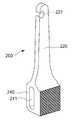
도 4는 보조기구의 일 예인 파워암의 외형을 도시하는 도면,
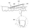
도 5는 투명커버와 버튼 및 파워암이 발치부위에 부착된 모습을 도시하는 도면,
도 6은 버튼과 파워암에 리본 와이즈 와이어와 파워체인이 체결된 모습을 예시하는 도면,
도 7은 버튼 2개에 리본 와이즈 와이어가 체결된 모습을 예시하는 도면,
도 8은 버튼 1개, 파워암 1개에 파워체인이 체결된 모습을 예시하는 도면,
도 9는 상하악 버튼 사이에 고무줄이 체결된 모습을 예시하는 도면이다.BRIEF DESCRIPTION OF THE DRAWINGS Fig. 1 is a diagram showing an example of a transparent calibration according to the prior art,
FIG. 2 is a flow chart for explaining a calibration method at the time of transparent calibration with an extraction according to the present invention in a time-
Fig. 3 is a view showing an outer shape of a button, which is an example of an auxiliary mechanism,
Fig. 4 is a view showing the outer shape of a power arm, which is an example of an auxiliary mechanism,
5 is a view showing a transparent cover, a button and a power arm attached to an extraction site,
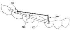
6 is a view illustrating a state in which a ribbon wise wire and a power chain are fastened to a button and a power arm,
7 is a view illustrating a state in which ribbon wise wires are fastened to two buttons,
8 is a view illustrating a state in which a power chain is fastened to one button and one power arm,
9 is a view illustrating a state in which an elastic band is fastened between upper and lower buttons.
이하에서는 본 발명의 바람직한 실시예 및 첨부하는 도면을 참조하여 본 발명을 상세히 설명하되, 도면의 동일한 참조부호는 동일한 구성요소를 지칭함을 전제하여 설명하기로 한다.DETAILED DESCRIPTION OF THE PREFERRED EMBODIMENT Hereinafter, the present invention will be described in detail with reference to preferred embodiments of the present invention and the accompanying drawings, wherein like reference numerals refer to like elements.
발명의 상세한 설명 또는 특허청구범위에서 어느 하나의 구성요소가 다른 구성요소를 "포함"한다고 할 때, 이는 특별히 반대되는 기재가 없는 한 당해 구성요소만으로 이루어지는 것으로 한정되어 해석되지 아니하며, 다른 구성요소들을 더 포함할 수 있는 것으로 이해되어야 한다.It is to be understood that when an element is referred to as being "comprising" another element in the description of the invention or in the claims, it is not to be construed as being limited to only that element, And the like.
이하에서는 발치를 동반한 투명교정시의 교정방법 및 투명교정에 필요한 보조장치가 구현된 일 예를 특정한 실시예를 통해 설명하기로 한다. 도 2는 본 발명에 의한 발치를 동반한 투명교정시의 교정방법을 시계열적으로 설명하는 플로우차트가 도시되어 있다.Hereinafter, a description will be made of a calibrating method for transparent correction with extraction and an example of implementing an assistant device for transparent correction, through specific embodiments. FIG. 2 is a flow chart illustrating a method of calibrating a transparent calibration according to the present invention in a time-series manner.
도 2에 도시한 바와 같이, 본 발명에 따른 발치를 동반한 투명교정시의 교정방법은, 발치대상인 치아 좌우의 2개 이상의 치아 협면과 대응되는 투명커버(1)의 판면을 절개하는 단계(S1)와, 버튼(100) 및/또는 파워암(200)을 상기 치아 협면에 부착하는 단계(S3)와, 파워체인(400) 또는 고무줄(500)을 상기 버튼(100) 및/또는 파워암(200)의 일측에 체결하는 단계(S5)를 포함하여 구성되어 있다.As shown in Fig. 2, the method of calibrating with clearance according to the present invention includes a step S1 of cutting the plate surface of the
일반적인 투명교정은 투명 레진(특수 강화 플라스틱)으로 된 투명커버(1)를 이용하여 치열을 교정하는 시술이지만, 본 발명에 따른 발치를 동반한 투명교정시의 교정방법은 투명커버(1) 뿐만 아니라, 별도의 보조기구를 이용하여 치아와 치아 사이의 견인이 이루어지도록 함으로써 투명교정의 장점을 유지하면서 보우잉 이펙트를 제거할 수 있도록 하기 위한 투명교정방법이다.In general, the transparent correction is a procedure of correcting the dental heat using the
이를 위하여, 우선, 교정 대상이 되는 치아에 삽입되는 투명커버(1)의 판면 일부를 절개하는 단계(S1)를 진행하게 되는데, 이는 교정대상이 되는 치아의 협면을 외부로 노출시켜 노출된 치아의 협면에 별도의 보조기구를 부착하기 위함이다.To this end, a step S1 of cutting a part of the plate surface of the
투명커버(1)의 판면이 절개되는 영역은 발치대상인 치아 좌우의 2개 이상의 치아 협면과 대응되는 투명커버(1)의 판면 영역이며, 투명커버(1)가 절개되는 면적은 치아와 잇몸의 경계선과 근접한 영역의 일부 면적으로 한정되는 것이 바람직하다.The area in which the plate surface of the
이는, 투명커버(1)의 절개 면적을 최소화함으로써 투명커버(1)의 역할인 치아와 치아 사이의 교정력을 제공시에 절개된 면적으로 인하여 치아 측으로 제공되는 교정력이 감소되지 않도록 하기 위함이다.This is so as not to reduce the corrective force provided to the teeth side due to the area cut in providing the orthodontic force between the tooth and the tooth, which is the role of the
발치대상인 치아 좌우의 투명커버(1) 일부 판면이 절개된 후에는 도 5 내지 도 9에 도시한 바와 같이, 발치와 전후에 모두 파워암(200)을 쓸지, 버튼(100)만 쓸지, 앞쪽에만 파워암(200)을 쓸지 버튼(100)과 파워암(200)을 함께 쓸지 등을 치아의 쓰러짐 정도에 따라 판단(S2)하여 선택적으로 적용한다.As shown in Figs. 5 to 9, after the incision of the
그 후, 상기 판단에 따라 버튼(100)과 파워암(200)을 외부로 노출되는 치아 협면에 부착(S3)하게 되는데, 이러한 버튼(100)과 파워암(200)은 상기 치아와 잇몸의 경계선으로부터 1 mm 내지 2.5 mm 이격된 치아 뿌리와 근접한 위치에 부착되도록 하는 것이 바람직하다.The
버튼(100)과 파워암(200)을 치아 뿌리와 근접한 위치의 치아 협면에 부착시킴은 버튼(100)과 파워암(200)을 통하여 전달되는 견인력이 치아 뿌리까지 정확하게 전달되도록 하여 치아 뿌리가 상호 견인되면서 교정이 이루어지도록 하기 위함이다.The
버튼(100)과 파워암(200)을 치아 뿌리와 이격된 위치의 치아 협면에 부착된 경우에는 버튼(100)과 파워암(200)을 통하여 전달되는 견인력이 치아의 뿌리까지 전달되지 않게 되어 치아 뿌리의 견인이 이루어지지 않고 치아 자체가 기울어질 수 있으므로 정확한 교정이 이루어지지 않게 되며, 이를 방지하기 위하여 버튼(100)과 파워암(200)은 치아 뿌리와 근접한 위치의 치아 협면에 부착되도록 하는 것이다.When the
그리고, 버튼(100)과 파워암(200)은 교정이 필요한 치아에 접착제를 이용하여 부착하게 되는데, 버튼(100)과 파워암(200)은 치아에 직접적으로 부착되므로 상기 접착제는 인체에 무해한 성분이어야 하며 법랑질 접착제와 같은 치과 전용 접착제를 사용한다.The
버튼(100) 및 파워암(200)이 치아와 접촉되는 버튼(100) 및 파워암(200)의 부착면은 그 판면에 메쉬 형태의 요철면이 형성되는 것이 바람직한데, 이는 접착제와 부착면 사이의 접촉 면적을 확장시킴으로써 접착력을 향상시키기 위함이다.It is preferable that the attachment surface of the
버튼(100)의 구성을 개략적으로 설명하면, 버튼(100)은 치아에 부착되는 부착면이 형성된 부착부재(110)와, 부착부재(110)와 이격되어 치아의 전면에 배치되는 커버부재(120)와, 부착부재(110)와 커버부재(120) 사이에 배치되어 부착부재(110)와 커버부재(120)를 연결하는 연결부재(130)를 포함하여 구성된다.The
그리고, 파워암(200)은 일부가 일정 길이 연장된 암(220)이 구비되고, 암(220)의 단부에는 걸쇠(221)가 형성된 구성을 갖는다.The
버튼(100)을 구성하는 부착부재(110), 커버부재(120) 및 연결부재(130)에 대한 내용 및 파워암(200)과 관련한 내용은 추후 투명교정에 필요한 보조장치를 설명시에 상세하게 언급하도록 하기로 한다.The content of the
도 5 내지 도 9에 도시한 바와 같이, 투명기구의 외부로 노출되는 치아의 협면에 버튼(100)과 파워암(200)의 부착이 완료되면, 파워체인(400)만 적용할 지, 리본 와이즈 와이어(300)만 적용할지 고무줄(500)만 적용할지 혹은 이들을 조합하여 적용할 지 여부를 판단(S4)하게 된다.5 to 9, when attachment of the
이러한 판단이 완료되면, 파워체인(400) 또는 고무줄(500)을 버튼(100)의 연결부재(130)와 연결부재(130) 또는 버튼(100)의 연결부재(130)와 파워암(200)의 걸쇠(221) 사이에 체결(S5)되도록 하여 치아 뿌리가 상호 견인되면서 교정이 이루어지도록 한다.The
파워체인(400)과 고무줄(500)은 치아 측으로 제공되어야 할 장력의 정도와 방향에 따라 선택적으로 사용될 수 있는데, 파워체인(400)의 경우에는 짧은 거리에 큰 장력을 제공할 경우에 사용되는 것이 바람직하며 고무줄(500)은 상대적으로 먼 거리에서 작은 장력을 제공시에 사용되는 것이 효과적이다.The
파워체인(400)과 고무줄(500)의 체결이 완료되면, 치아 협면에 부착된 버튼(100)과 파워암(200)에 형성된 각각 튜브(131, 211)에 리본 와이즈 와이어(300)를 삽입하게 되며, 리본 와이즈 와이어(300)의 삽입이 완료되면 리본 와이즈 와이어(300)의 양 끝단을 절곡함으로써 리본 와이즈 와이어(300)가 삽입된 상태를 유지함과 동시에 리본 와이즈 와이어(300)에 의하여 발생되는 장력이 치아 측으로 전달되도록 함으로써 치아의 교정이 이루어지도록 한다.When the
본 발명에 따른 발치를 동반한 투명교정시의 교정방법은 투명교정장치를 사용하여 치아 교정 치료를 실시하되, 보조기구를 사용함으로써 발치 부위 주변 치아의 치관부위(dental crown) 뿐만 아니라 치근부위(dental root)까지 견인을 가능케 하는 효과가 있다. 이에 의할 때, 투명교정의 장점을 그대로 유지하면서도 투명 교정장치를 이용하는 발치 교정시의 주요한 문제점으로 알려진 보우잉 이펙트가 제거될 수 있다.The orthodontic method for orthodontic correction with an extraction according to the present invention is to perform a orthodontic treatment using a transparent correcting device. By using an auxiliary device, not only a dental crown of a tooth around an extraction site but also a dental crown root). In this case, the bougie effect, which is known to be a major problem in orthodontic correction using a transparent orthodontic device, can be eliminated while still retaining the advantages of transparent correction.
그리고, 투명 레진 재질로 버튼(100) 또는 파워암(200) 형태의 보조기구를 협면에 부착하여 치아 교정을 실시하되, 그 구조상 미관의 손상을 최소화할 수 있으며 생활상 불편함이 최소화된다.The teeth of the
한편, 본 발명에 따른 투명교정에 필요한 보조장치는, 투명커버(1)의 절개된 판면을 통하여 외부로 노출되는 치아의 협면에 부착되는 부재로서 크게 버튼(100)과, 파워암(200)을 포함하여 구성된다.The assistant device required for transparent correction according to the present invention includes a
도 3에 도시한 바와 같이, 버튼(100)은, 버튼(100)은 상기 치아에 부착되는 부착면이 형성된 부착부재(110)와, 부착부재(110)와 이격되어 상기 치아의 전면에 배치되는 커버부재(120)와, 부착부재(110)와 커버부재(120) 사이에 배치되어 부착부재(110)와 커버부재(120)를 연결하는 연결부재(130)를 포함하고, 연결부재(130)에는 리본 와이즈 와이어(300)가 삽입되는 튜브(131)가 관통 형성되어 있다.3, the
부착부재(110)는 치아의 협면보다는 작은 면적을 갖도록 형성되어 치아와 직접적으로 접촉되어 부착되는 부재로서, 부착부재(110)에 형성된 부착면의 판면에는 메쉬 형태의 요철면이 형성되는 것이 바람직하다.The
이는 접착제와 부착면 사이의 접촉면적이 증대되도록 함으로써 부착력을 향상시킴으로써 버튼(100)이 견고하게 치아의 협면에 부착되도록 하기 위함이다.This is to increase the contact area between the adhesive and the attachment surface so that the
커버부재(120)는 부착부재(110)의 전방에 배치되어 버튼(100)이 치아의 협면에 부착시에 부착부재(110)가 외부로 노출되지 않도록 차폐시키는 역할을 하며, 커버부재(120)의 외벽은 둥근 곡면으로 납작하게 형성되어 치아 방향보다 잇몸 방향으로 더 길도록 세로 길이가 4 mm 내지 6 mm 가 되도록 형성되는데, 바람직하게는 5 mm로 형성될 수 있다.The cover member 120 is disposed in front of the
커버부재(120)의 외벽이 굴곡지게 형성됨은 교정자가 치아의 협면에 부착되는 버튼(100)의 이질감을 최대한 적게 느끼도록 함으로써 착용감을 높이기 위함이며, 외벽이 치아 방향보다 잇몸 방향으로 더 길도록 형성됨은 도 9와 같이 상하로 고무줄을 적용시 환자로 하여금 고무줄을 쉽게 걸 수 있게 하기 위함이다.The outer wall of the cover member 120 is formed so as to be bent so as to enhance the feeling of wearing by minimizing the feeling of unevenness of the
연결부재(130)는 부착부재(110)와 커버부재(120) 사이에 배치되어 부착부재(110)와 커버부재(120)를 연결하는 역할을 하며, 연결부재(130)에는 가로 방향으로 관통 형성되는 튜브(131)가 구비되어 리본 와이즈 와이어(300)가 삽입되도록 한다.The
이러한 튜브(131)의 종단면은 리본 와이즈 와이어(300)의 종단면과 대응하는 형상으로 형성되어, 세로 길이가 0.025 인치로 형성되고 가로 길이가 0.018인치로 형성되어 세로 길이가 가로 길이보다 더 길게 형성된다. 이는 치아를 견인할 시 치아가 발치와쪽으로 쓰러지는 힘에 대항하는 탄성력을 효과적으로 제공하여 보우잉 이펙트를 줄이기 위함이다.The longitudinal section of the
도 4에 도시한 바와 같이, 파워암(200)은 상기 치아에 부착되는 부착면이 형성된 본체(210)와, 본체(210)의 일부가 일정 길이 연장된 암(220)과, 암(220)의 단부에 형성된 걸쇠(221)를 포함하고, 본체(210)에는 리본 와이즈 와이어(300)가 삽입되는 튜브(211)가 관통 형성되어 있다.4, the
본체(210)의 일측에는 파워암(200)을 치아의 협면에 부착할 수 있는 부착면이 형성되는데, 이러한 부착면의 판면은 메쉬 형태의 요철면이 형성되는 것이 바람직한데, 이는 접착제와 부착면 사이의 접촉면적이 증대되도록 함으로써 부착력을 향상시킴으로써 파워암(200)이 견고하게 치아의 협면에 부착되도록 하기 위함이다.On one side of the
그리고, 본체(210)에 형성된 튜브(211)의 종단면은 리본 와이즈 와이어(300)의 종단면과 대응하는 형상으로 형성되어, 세로 길이가 0.025 인치로 형성되고 가로 길이가 0.018인치로 형성되어 있다.The longitudinal section of the
즉, 버튼(100)에 형성된 튜브(131)와 마찬가지로 세로 길이가 가로 길이보다 더 길게 형성되는데, 이는 치아를 견인할 시 치아가 발치와쪽으로 쓰러지는 힘에 대항하는 탄성력을 효과적으로 제공하여 보우잉 이펙트를 줄이기 위함이다.In other words, like the
버튼(100) 및 파워암(200)의 튜브(131, 211)에 삽입되어 설치되는 와이어는 풀 아치 와이어가 아니며 풀 아치 와이어보다는 상대적으로 길이가 짧은 리본 와이즈 와이어(300)를 사용하게 되는데, 이는 와이어가 짧아서 와이어를 따라 치아가 주로 견인되는 것이라기 보다는 주로 파워체인(400)을 따라서 견인하되 치아가 기울어지지 않도록 하기 위함이다.The wire inserted into the
암(220)은 외벽이 둥근 곡면으로 납작하며 치아 방향보다 잇몸 방향으로 더 길도록 4 mm 내지 5 mm로 형성되며, 암(220)은 전체적인 형상이 상기 치아와 잇몸을 따라 접하는 형태로 굴곡지게 형성되어 있다.The
이는, 버튼(100)의 커버부재(120) 외벽이 굴곡지게 형성됨과 마찬가지로 교정자가 치아의 협면에 부착되는 파워암(200)의 이질감을 최대한 적게 느끼도록 함으로써 착용감을 높이기 위함이다.This is to enhance the feeling of fit by making the outer surface of the cover member 120 of the
본체(210)의 일측에 일정 길이 연장된 암(220)의 길이는 4 mm 내지 5 mm 정도가 되도록 형성되어 본체(210)의 길이까지 합하면 파워암(200)의 전체적인 길이는 8 mm 정도가 되도록 형성된다.The length of the
이러한 암(220)은 종래의 브라켓이나 와이어에 후크가 1 mm 내지 1.5 mm 정도 돌출된 구성과는 달리 4 mm 내지 5 mm 정도가 되도록 잇몸의 윗쪽까지 연장되게 한다. 이는 힘의 적용부위를 보다 치아의 무게중심에 가깝게 하여 치아가 보다 평행적으로 견인될 수 있게 한다. 이 또한 튜브에 리본와이즈 와이어를 삽입하는 이유와 같이, 치아의 치관부위만 발치와쪽으로 쓰러지는 보우잉 이펙트를 제거하기 위함이다.The
이상 몇 가지의 실시예를 통해 본 발명의 기술적 사상을 살펴보았다.The technical idea of the present invention has been described through several embodiments.
본 발명이 속하는 기술분야에서 통상의 지식을 가진 자가 본 발명의 기재사항으로부터 상기 살펴본 실시예를 다양하게 변형하거나 변경할 수 있음은 자명하다. 또한, 비록 명시적으로 도시되거나 설명되지 아니하였다 하여도 본 발명이 속하는 기술분야에서 통상의 지식을 가진 자가 본 발명의 기재사항으로부터 본 발명에 의한 기술적 사상을 포함하는 다양한 형태의 변형을 할 수 있음은 자명하며, 이는 여전히 본 발명의 권리범위에 속한다. 첨부하는 도면을 참조하여 설명된 상기의 실시예들은 본 발명을 설명하기 위한 목적으로 기술된 것이며 본 발명의 권리범위는 이러한 실시예에 국한되지 아니한다.It will be apparent to those skilled in the art that various changes and modifications may be made to the embodiments described above from the description of the present invention. Further, although not explicitly shown or described, those skilled in the art can make various modifications including the technical idea of the present invention from the description of the present invention Which is still within the scope of the present invention. The above-described embodiments described with reference to the accompanying drawings are for the purpose of illustrating the present invention, and the scope of the present invention is not limited to these embodiments.
본 발명은 치아교정 기술분야에 적용될 수 있다.The present invention can be applied to the field of orthodontic technology.
1 : 투명커버100 : 버튼
110 : 부착부재120 : 커버부재
130 : 연결부재131 : 튜브
200 : 파워암210 : 본체
211 : 튜브220 : 암
221 : 걸쇠300 : 리본 와이즈 와이어
400 : 파워체인500 : 고무줄1: Transparent cover 100: Button
110: attachment member 120: cover member
130: connecting member 131: tube
200: power arm 210: main body
211: tube 220: arm
221: shackle 300: ribbon wise wire
400: Power chain 500: Rubber band
Claims (8)
Translated fromKorean상기 투명커버의 절개에 의해 노출된 치아 협면에 부착되는 버튼 및 파워암을 포함하며,
상기 버튼과 상기 파워암이 체결부재로 체결되는 투명교정에 필요한 보조장치.A transparent cover in which a plate surface corresponding to at least two tooth surfaces adjacent to a tooth to be extracted is cut out; And
A button and a power arm attached to the tooth surface exposed by the incision of the transparent cover,
And an auxiliary device required for transparent correction in which the button and the power arm are fastened by the fastening member.
상기 버튼은 상기 치아에 부착되는 부착면이 형성된 부착부재와, 상기 부착부재와 이격되어 상기 치아의 전면에 배치되는 커버부재와, 상기 부착부재와 상기 커버부재 사이에 배치되어 상기 부착부재와 상기 커버부재를 연결하는 연결부재를 포함하고, 상기 연결부재에는 리본 와이즈 와이어가 삽입되는 튜브가 관통 형성되는 투명교정에 필요한 보조장치.The method according to claim 1,
Wherein the button comprises a mounting member having an attachment surface to be attached to the tooth, a cover member spaced apart from the attachment member and disposed on the front surface of the tooth, and a cover member disposed between the attachment member and the cover member, And a connection member for connecting the member, wherein the connection member is formed with a tube through which a ribbon wise wire is inserted, and is necessary for transparent correction.
상기 커버부재의 외벽은 둥근 곡면으로 납작하게 형성되어 치아 방향보다 잇몸 방향으로 더 길도록 세로 길이가 4 mm 내지 6 mm로 형성되는 투명교정에 필요한 보조장치.3. The method of claim 2,
Wherein the outer wall of the cover member is formed flat with a rounded curved surface and is formed to have a vertical length of 4 mm to 6 mm so as to be longer in the direction of the gingiva than a tooth direction.
상기 튜브의 종단면은 상기 리본 와이즈 와이어의 종단면과 대응하는 형상으로 형성되어, 세로 길이가 0.025 인치로 형성되고 가로 길이가 0.018인치로 형성되는 투명교정에 필요한 보조장치.3. The method of claim 2,
Wherein the longitudinal section of the tube is formed in a shape corresponding to a longitudinal section of the ribbon wise wire, the longitudinal length being 0.025 inches and the transverse length being 0.018 inches.
상기 파워암은 상기 치아에 부착되는 부착면이 형성된 본체와, 상기 본체의 일부가 일정 길이 연장된 암과, 상기 암의 단부에 형성된 걸쇠를 포함하고, 상기 본체에는 리본 와이즈 와이어가 삽입되는 튜브가 관통 형성되는 투명교정에 필요한 보조장치.The method according to claim 1,
The power arm includes a main body having an attachment surface to be attached to the teeth, an arm having a part of the main body extended to a predetermined length, and a latch formed at an end of the arm, wherein a tube into which the ribbon- Auxiliary device required for transparent calibration to be formed through.
Priority Applications (1)
| Application Number | Priority Date | Filing Date | Title |
|---|---|---|---|
| KR1020160028923AKR101678546B1 (en) | 2016-03-10 | 2016-03-10 | A method for clear aligner orthodontic therapy in extraction patients and its auxiliary appliances |
Applications Claiming Priority (1)
| Application Number | Priority Date | Filing Date | Title |
|---|---|---|---|
| KR1020160028923AKR101678546B1 (en) | 2016-03-10 | 2016-03-10 | A method for clear aligner orthodontic therapy in extraction patients and its auxiliary appliances |
Publications (1)
| Publication Number | Publication Date |
|---|---|
| KR101678546B1true KR101678546B1 (en) | 2016-11-22 |
Family
ID=57540068
Family Applications (1)
| Application Number | Title | Priority Date | Filing Date |
|---|---|---|---|
| KR1020160028923AActiveKR101678546B1 (en) | 2016-03-10 | 2016-03-10 | A method for clear aligner orthodontic therapy in extraction patients and its auxiliary appliances |
Country Status (1)
| Country | Link |
|---|---|
| KR (1) | KR101678546B1 (en) |
Cited By (4)
| Publication number | Priority date | Publication date | Assignee | Title |
|---|---|---|---|---|
| WO2018101785A1 (en)* | 2016-12-01 | 2018-06-07 | 조건제 | Hybrid orthodontic appliance and method for manufacturing same |
| KR20190143823A (en)* | 2018-06-21 | 2019-12-31 | 청 시앙 훙 | Removable orthodontic device |
| KR102250006B1 (en)* | 2019-10-31 | 2021-05-07 | 안장훈 | Apparatus for posterior retraction of anterior teeth |
| KR102619800B1 (en)* | 2022-12-22 | 2023-12-29 | 박선영 | Apparatus, method and recording medium of determining orthodontic method based on condition of patient |
Citations (6)
| Publication number | Priority date | Publication date | Assignee | Title |
|---|---|---|---|---|
| KR100805752B1 (en)* | 2006-09-08 | 2008-02-21 | 김옥경 | Braces |
| KR20120002067U (en)* | 2012-02-07 | 2012-03-20 | 주식회사 월드바이오텍 | Button for correction of irregular teeth |
| KR200460320Y1 (en)* | 2011-12-12 | 2012-05-21 | 윤성원 | Orthodontic Appliance |
| KR101183890B1 (en)* | 2011-11-16 | 2012-09-19 | 주식회사 이클리어인터내셔날 | Clear aligner comprising button and method thereof |
| KR20140110047A (en) | 2012-01-06 | 2014-09-16 | 퀄컴 인코포레이티드 | Wireless display with multiscreen service |
| KR20140130786A (en) | 2013-05-02 | 2014-11-12 | 한국과학기술원 | Super-resolution Apparatus and Method using LOR reconstruction based cone-beam in PET image |
- 2016
- 2016-03-10KRKR1020160028923Apatent/KR101678546B1/enactiveActive
Patent Citations (6)
| Publication number | Priority date | Publication date | Assignee | Title |
|---|---|---|---|---|
| KR100805752B1 (en)* | 2006-09-08 | 2008-02-21 | 김옥경 | Braces |
| KR101183890B1 (en)* | 2011-11-16 | 2012-09-19 | 주식회사 이클리어인터내셔날 | Clear aligner comprising button and method thereof |
| KR200460320Y1 (en)* | 2011-12-12 | 2012-05-21 | 윤성원 | Orthodontic Appliance |
| KR20140110047A (en) | 2012-01-06 | 2014-09-16 | 퀄컴 인코포레이티드 | Wireless display with multiscreen service |
| KR20120002067U (en)* | 2012-02-07 | 2012-03-20 | 주식회사 월드바이오텍 | Button for correction of irregular teeth |
| KR20140130786A (en) | 2013-05-02 | 2014-11-12 | 한국과학기술원 | Super-resolution Apparatus and Method using LOR reconstruction based cone-beam in PET image |
Cited By (7)
| Publication number | Priority date | Publication date | Assignee | Title |
|---|---|---|---|---|
| WO2018101785A1 (en)* | 2016-12-01 | 2018-06-07 | 조건제 | Hybrid orthodontic appliance and method for manufacturing same |
| KR20180062666A (en)* | 2016-12-01 | 2018-06-11 | 조건제 | Teeth Alignment Device And Manufacturing Method Thereof |
| KR101997562B1 (en)* | 2016-12-01 | 2019-07-08 | 조건제 | Teeth Alignment Device And Manufacturing Method Thereof |
| KR20190143823A (en)* | 2018-06-21 | 2019-12-31 | 청 시앙 훙 | Removable orthodontic device |
| KR102229745B1 (en) | 2018-06-21 | 2021-03-19 | 청 시앙 훙 | Removable orthodontic device |
| KR102250006B1 (en)* | 2019-10-31 | 2021-05-07 | 안장훈 | Apparatus for posterior retraction of anterior teeth |
| KR102619800B1 (en)* | 2022-12-22 | 2023-12-29 | 박선영 | Apparatus, method and recording medium of determining orthodontic method based on condition of patient |
Similar Documents
| Publication | Publication Date | Title |
|---|---|---|
| KR101723674B1 (en) | Lingual orthodontic system | |
| KR100805752B1 (en) | Braces | |
| KR101510857B1 (en) | Transparent orthodontic device | |
| US20100015565A1 (en) | Orthodontic Devices | |
| KR101678546B1 (en) | A method for clear aligner orthodontic therapy in extraction patients and its auxiliary appliances | |
| KR101343129B1 (en) | Tooth correction device | |
| JP6643234B2 (en) | Labial attachment device for use with orthodontic aids and lingual appliance systems | |
| CN104622590B (en) | Traction device for mandibular impacted wisdom teeth | |
| KR20130125132A (en) | Orthodontic device | |
| KR101565803B1 (en) | Tooth correction device | |
| KR101592421B1 (en) | Orthodontic appliance | |
| US7713057B2 (en) | Oral mucous membrane protector for orthodontic applications | |
| US20080102414A1 (en) | Posterior bite ramps, kits, and methods of use to correct class ii and/or class iii malocclusions | |
| CN108478296A (en) | Cast type backteeth forces down appliance | |
| US4856992A (en) | Preformed bands with lingual extensions | |
| KR101249175B1 (en) | Orthodontic apparatus | |
| US20140242536A1 (en) | Mandibular attachment for correction of malocclusion | |
| US20220233277A1 (en) | Orthodontic methods and devices | |
| CN116473697A (en) | Lingual fixed retainer | |
| CN215458818U (en) | Impacted tooth corrector | |
| CN103230306A (en) | Ring frame type molar uprighter for correcting mandibular molars suffering forward lower impaction | |
| KR101379618B1 (en) | Ring bracket for orthodontics | |
| CN114376747A (en) | Appliance suitable for intermaxillary traction and design method thereof | |
| KR101129136B1 (en) | Wire for Orthodontic Treatment And Orthodontic Device Having The Same | |
| KR101888990B1 (en) | Orthodontic appliance and assembly including the same |
Legal Events
| Date | Code | Title | Description |
|---|---|---|---|
| PA0109 | Patent application | St.27 status event code:A-0-1-A10-A12-nap-PA0109 | |
| PA0201 | Request for examination | St.27 status event code:A-1-2-D10-D11-exm-PA0201 | |
| PA0302 | Request for accelerated examination | St.27 status event code:A-1-2-D10-D17-exm-PA0302 St.27 status event code:A-1-2-D10-D16-exm-PA0302 | |
| P11-X000 | Amendment of application requested | St.27 status event code:A-2-2-P10-P11-nap-X000 | |
| P13-X000 | Application amended | St.27 status event code:A-2-2-P10-P13-nap-X000 | |
| D13-X000 | Search requested | St.27 status event code:A-1-2-D10-D13-srh-X000 | |
| D14-X000 | Search report completed | St.27 status event code:A-1-2-D10-D14-srh-X000 | |
| PE0902 | Notice of grounds for rejection | St.27 status event code:A-1-2-D10-D21-exm-PE0902 | |
| E13-X000 | Pre-grant limitation requested | St.27 status event code:A-2-3-E10-E13-lim-X000 | |
| P11-X000 | Amendment of application requested | St.27 status event code:A-2-2-P10-P11-nap-X000 | |
| P13-X000 | Application amended | St.27 status event code:A-2-2-P10-P13-nap-X000 | |
| E90F | Notification of reason for final refusal | ||
| PE0902 | Notice of grounds for rejection | St.27 status event code:A-1-2-D10-D21-exm-PE0902 | |
| P11-X000 | Amendment of application requested | St.27 status event code:A-2-2-P10-P11-nap-X000 | |
| P13-X000 | Application amended | St.27 status event code:A-2-2-P10-P13-nap-X000 | |
| E701 | Decision to grant or registration of patent right | ||
| PE0701 | Decision of registration | St.27 status event code:A-1-2-D10-D22-exm-PE0701 | |
| GRNT | Written decision to grant | ||
| PR0701 | Registration of establishment | St.27 status event code:A-2-4-F10-F11-exm-PR0701 | |
| PR1002 | Payment of registration fee | St.27 status event code:A-2-2-U10-U11-oth-PR1002 Fee payment year number:1 | |
| PG1601 | Publication of registration | St.27 status event code:A-4-4-Q10-Q13-nap-PG1601 | |
| FPAY | Annual fee payment | Payment date:20191030 Year of fee payment:4 | |
| PR1001 | Payment of annual fee | St.27 status event code:A-4-4-U10-U11-oth-PR1001 Fee payment year number:4 | |
| PR1001 | Payment of annual fee | St.27 status event code:A-4-4-U10-U11-oth-PR1001 Fee payment year number:5 | |
| PR1001 | Payment of annual fee | St.27 status event code:A-4-4-U10-U11-oth-PR1001 Fee payment year number:6 | |
| PR1001 | Payment of annual fee | St.27 status event code:A-4-4-U10-U11-oth-PR1001 Fee payment year number:7 | |
| PR1001 | Payment of annual fee | St.27 status event code:A-4-4-U10-U11-oth-PR1001 Fee payment year number:8 | |
| PR1001 | Payment of annual fee | St.27 status event code:A-4-4-U10-U11-oth-PR1001 Fee payment year number:9 | |
| PR1001 | Payment of annual fee | St.27 status event code:A-4-4-U10-U11-oth-PR1001 Fee payment year number:10 |