KR101677334B1 - Refrigerator door - Google Patents
Refrigerator doorDownload PDFInfo
- Publication number
- KR101677334B1 KR101677334B1KR1020140145534AKR20140145534AKR101677334B1KR 101677334 B1KR101677334 B1KR 101677334B1KR 1020140145534 AKR1020140145534 AKR 1020140145534AKR 20140145534 AKR20140145534 AKR 20140145534AKR 101677334 B1KR101677334 B1KR 101677334B1
- Authority
- KR
- South Korea
- Prior art keywords
- display
- delete delete
- sensor
- cover
- front panel
- Prior art date
- Legal status (The legal status is an assumption and is not a legal conclusion. Google has not performed a legal analysis and makes no representation as to the accuracy of the status listed.)
- Active
Links
Images


Classifications
- G—PHYSICS
- G09—EDUCATION; CRYPTOGRAPHY; DISPLAY; ADVERTISING; SEALS
- G09G—ARRANGEMENTS OR CIRCUITS FOR CONTROL OF INDICATING DEVICES USING STATIC MEANS TO PRESENT VARIABLE INFORMATION
- G09G3/00—Control arrangements or circuits, of interest only in connection with visual indicators other than cathode-ray tubes
- G09G3/20—Control arrangements or circuits, of interest only in connection with visual indicators other than cathode-ray tubes for presentation of an assembly of a number of characters, e.g. a page, by composing the assembly by combination of individual elements arranged in a matrix no fixed position being assigned to or needed to be assigned to the individual characters or partial characters
- G09G3/22—Control arrangements or circuits, of interest only in connection with visual indicators other than cathode-ray tubes for presentation of an assembly of a number of characters, e.g. a page, by composing the assembly by combination of individual elements arranged in a matrix no fixed position being assigned to or needed to be assigned to the individual characters or partial characters using controlled light sources
- G09G3/30—Control arrangements or circuits, of interest only in connection with visual indicators other than cathode-ray tubes for presentation of an assembly of a number of characters, e.g. a page, by composing the assembly by combination of individual elements arranged in a matrix no fixed position being assigned to or needed to be assigned to the individual characters or partial characters using controlled light sources using electroluminescent panels
- G09G3/32—Control arrangements or circuits, of interest only in connection with visual indicators other than cathode-ray tubes for presentation of an assembly of a number of characters, e.g. a page, by composing the assembly by combination of individual elements arranged in a matrix no fixed position being assigned to or needed to be assigned to the individual characters or partial characters using controlled light sources using electroluminescent panels semiconductive, e.g. using light-emitting diodes [LED]
- G09G3/3208—Control arrangements or circuits, of interest only in connection with visual indicators other than cathode-ray tubes for presentation of an assembly of a number of characters, e.g. a page, by composing the assembly by combination of individual elements arranged in a matrix no fixed position being assigned to or needed to be assigned to the individual characters or partial characters using controlled light sources using electroluminescent panels semiconductive, e.g. using light-emitting diodes [LED] organic, e.g. using organic light-emitting diodes [OLED]
- G—PHYSICS
- G06—COMPUTING OR CALCULATING; COUNTING
- G06F—ELECTRIC DIGITAL DATA PROCESSING
- G06F3/00—Input arrangements for transferring data to be processed into a form capable of being handled by the computer; Output arrangements for transferring data from processing unit to output unit, e.g. interface arrangements
- G06F3/01—Input arrangements or combined input and output arrangements for interaction between user and computer
- G06F3/03—Arrangements for converting the position or the displacement of a member into a coded form
- G06F3/041—Digitisers, e.g. for touch screens or touch pads, characterised by the transducing means
- F—MECHANICAL ENGINEERING; LIGHTING; HEATING; WEAPONS; BLASTING
- F24—HEATING; RANGES; VENTILATING
- F24C—DOMESTIC STOVES OR RANGES ; DETAILS OF DOMESTIC STOVES OR RANGES, OF GENERAL APPLICATION
- F24C15/00—Details
- F24C15/02—Doors specially adapted for stoves or ranges
- F—MECHANICAL ENGINEERING; LIGHTING; HEATING; WEAPONS; BLASTING
- F24—HEATING; RANGES; VENTILATING
- F24C—DOMESTIC STOVES OR RANGES ; DETAILS OF DOMESTIC STOVES OR RANGES, OF GENERAL APPLICATION
- F24C7/00—Stoves or ranges heated by electric energy
- F24C7/08—Arrangement or mounting of control or safety devices
- F24C7/082—Arrangement or mounting of control or safety devices on ranges, e.g. control panels, illumination
- F24C7/086—Arrangement or mounting of control or safety devices on ranges, e.g. control panels, illumination touch control
- F—MECHANICAL ENGINEERING; LIGHTING; HEATING; WEAPONS; BLASTING
- F25—REFRIGERATION OR COOLING; COMBINED HEATING AND REFRIGERATION SYSTEMS; HEAT PUMP SYSTEMS; MANUFACTURE OR STORAGE OF ICE; LIQUEFACTION SOLIDIFICATION OF GASES
- F25D—REFRIGERATORS; COLD ROOMS; ICE-BOXES; COOLING OR FREEZING APPARATUS NOT OTHERWISE PROVIDED FOR
- F25D23/00—General constructional features
- F25D23/02—Doors; Covers
- F25D23/028—Details
- F—MECHANICAL ENGINEERING; LIGHTING; HEATING; WEAPONS; BLASTING
- F25—REFRIGERATION OR COOLING; COMBINED HEATING AND REFRIGERATION SYSTEMS; HEAT PUMP SYSTEMS; MANUFACTURE OR STORAGE OF ICE; LIQUEFACTION SOLIDIFICATION OF GASES
- F25D—REFRIGERATORS; COLD ROOMS; ICE-BOXES; COOLING OR FREEZING APPARATUS NOT OTHERWISE PROVIDED FOR
- F25D29/00—Arrangement or mounting of control or safety devices
- F25D29/005—Mounting of control devices
- G—PHYSICS
- G06—COMPUTING OR CALCULATING; COUNTING
- G06F—ELECTRIC DIGITAL DATA PROCESSING
- G06F3/00—Input arrangements for transferring data to be processed into a form capable of being handled by the computer; Output arrangements for transferring data from processing unit to output unit, e.g. interface arrangements
- G06F3/01—Input arrangements or combined input and output arrangements for interaction between user and computer
- G06F3/03—Arrangements for converting the position or the displacement of a member into a coded form
- G06F3/033—Pointing devices displaced or positioned by the user, e.g. mice, trackballs, pens or joysticks; Accessories therefor
- G06F3/0354—Pointing devices displaced or positioned by the user, e.g. mice, trackballs, pens or joysticks; Accessories therefor with detection of 2D relative movements between the device, or an operating part thereof, and a plane or surface, e.g. 2D mice, trackballs, pens or pucks
- G06F3/03547—Touch pads, in which fingers can move on a surface
- H—ELECTRICITY
- H03—ELECTRONIC CIRCUITRY
- H03K—PULSE TECHNIQUE
- H03K17/00—Electronic switching or gating, i.e. not by contact-making and –breaking
- H03K17/94—Electronic switching or gating, i.e. not by contact-making and –breaking characterised by the way in which the control signals are generated
- H03K17/96—Touch switches
- H03K17/964—Piezoelectric touch switches
- H03K17/9643—Piezoelectric touch switches using a plurality of detectors, e.g. keyboard
- F—MECHANICAL ENGINEERING; LIGHTING; HEATING; WEAPONS; BLASTING
- F25—REFRIGERATION OR COOLING; COMBINED HEATING AND REFRIGERATION SYSTEMS; HEAT PUMP SYSTEMS; MANUFACTURE OR STORAGE OF ICE; LIQUEFACTION SOLIDIFICATION OF GASES
- F25D—REFRIGERATORS; COLD ROOMS; ICE-BOXES; COOLING OR FREEZING APPARATUS NOT OTHERWISE PROVIDED FOR
- F25D2400/00—General features of, or devices for refrigerators, cold rooms, ice-boxes, or for cooling or freezing apparatus not covered by any other subclass
- F25D2400/36—Visual displays
- F25D2400/361—Interactive visual displays
- H—ELECTRICITY
- H03—ELECTRONIC CIRCUITRY
- H03K—PULSE TECHNIQUE
- H03K2217/00—Indexing scheme related to electronic switching or gating, i.e. not by contact-making or -breaking covered by H03K17/00
- H03K2217/94—Indexing scheme related to electronic switching or gating, i.e. not by contact-making or -breaking covered by H03K17/00 characterised by the way in which the control signal is generated
- H03K2217/96—Touch switches
- H03K2217/96015—Constructional details for touch switches
Landscapes
- Engineering & Computer Science (AREA)
- General Engineering & Computer Science (AREA)
- Physics & Mathematics (AREA)
- Theoretical Computer Science (AREA)
- Chemical & Material Sciences (AREA)
- Combustion & Propulsion (AREA)
- Mechanical Engineering (AREA)
- Thermal Sciences (AREA)
- General Physics & Mathematics (AREA)
- Human Computer Interaction (AREA)
- Computer Hardware Design (AREA)
- Cold Air Circulating Systems And Constructional Details In Refrigerators (AREA)
- Devices That Are Associated With Refrigeration Equipment (AREA)
- Refrigerator Housings (AREA)
- User Interface Of Digital Computer (AREA)
- Push-Button Switches (AREA)
Abstract
Translated fromKoreanDescription
Translated fromKorean본 발명은 냉장고 도어에 관한 것이다.The present invention relates to a refrigerator door.
일반적으로 가전제품에 사용되는 터치센서 어셈블리는, 사용자의 누름 조작을 인식하여 가전제품의 동작을 위한 신호를 발생시키게 되며, 정전용량 센서 또는 저항셀 방식의 센서 등을 포함하며, 이들 센서에서 사용자의 터치 조작을 감지하고 이를 신호 처리하여 가전제품의 동작을 가능하게 하는 구성을 가진다.2. Description of the Related Art A touch sensor assembly used in a home appliance generally recognizes a user's pressing operation and generates a signal for operation of a home appliance. The touch sensor assembly includes a capacitive sensor or a resistance cell type sensor. A touch operation is detected and signal processing is performed to enable the operation of the household appliances.
그리고, 최근의 가전제품들은 외관의 개선을 위해 외관이 스틸이나 유리 또는 이와 유사한 코팅이 형성된 소재의 외장부재가 사용되며, 이들 외장부재의 터치 조작시 이를 인식할 수 있도록 하는 터치센서 어셈블리 또한 개발되고 있다.In recent years, in order to improve the external appearance of the electronic appliances, an exterior member made of a material having a steel or glass or a similar coating is used, and a touch sensor assembly is also developed have.
한편, 냉장고는 도어에 의해 차폐되는 내부의 저장공간에 음식물을 저온 저장할 수 있도록 하는 가전 기기이다. 이를 위해 냉장고는 냉동사이클을 순환하는 냉매와의 열교환을 통해 발생하는 냉기를 이용하여 저장공간의 내부를 냉각함으로써 저장된 음식물들을 최적 상태로 보관할 수 있도록 구성된다.On the other hand, a refrigerator is a household appliance that can store food at a low temperature in an internal storage space that is shielded by a door. To this end, the refrigerator is configured to cool the inside of the storage space by using cool air generated through heat exchange with the refrigerant circulating in the refrigeration cycle, thereby storing the stored food in an optimum state.
상기 냉장고 내부는 냉장실과 냉동실로 구성될 수 있으며, 상기 냉장실과 냉동실의 내부에는 선반, 서랍, 바스켓 등의 수납부재가 구비된다. 그리고, 상기 냉장실과 냉동실은 도어에 의해 차폐된다. 상기 냉장고는 상기 냉장실과 냉동실의 배치와 및 도어의 형태에 따라 다양하게 분류된다.The inside of the refrigerator may include a refrigerator compartment and a freezer compartment. Inside the refrigerator compartment and the freezer compartment, a receiving member such as a shelf, a drawer, and a basket is provided. The refrigerator compartment and the freezer compartment are shielded by a door. The refrigerator is variously classified according to the arrangement of the refrigerator compartment and the freezer compartment and the type of the door.
최근의 냉장고는 고급화 및 다기능화의 추세에 따라 외관이 한층 개선되고 다양한 편의장치를 구비한 냉장고가 출시되고 있다.[0002] Recently, refrigerators having improved appearance and improved convenience and versatility have been introduced.
예컨데, 외관을 구성하는 외장부재가 스틸이나 유리 또는 이와 유사한 코팅이 형성된 소재로 형성되고, 사용자의 조작을 용이하게 하기 위한 다양한 구조의 디스플레이와 조작 장치들이 채용되는 냉장고가 개발되고 있다.For example, there has been developed a refrigerator in which an outer member constituting an outer appearance is formed of a material having steel or glass or a similar coating formed thereon, and a display and operating devices of various structures are employed to facilitate the user's operation.
대한민국등록특허 제10-0634365호에는 이와 같은 종래 기술에 의한 냉장고가 개시되어 있다.Korean Patent No. 10-0634365 discloses such a conventional refrigerator.
본 발명의 실시 예는, 외장부재와의 밀착 상태를 유지하여 외장부재의 터치 조작시의 변위를 정확하게 감지하여 인식률이 향상된 터치센서 어셈블리 및 터치센서 어셈블리가 구비된 냉장고를 제공하는 것을 목적으로 한다.SUMMARY OF THE INVENTION It is an object of the present invention to provide a refrigerator having a touch sensor assembly and a touch sensor assembly with an improved recognition rate by accurately detecting the displacement of the exterior member during touch operation by maintaining a close contact state with the exterior member.
또한, 본 발명의 실시 예는, 정전기에 의한 센서 제어부의 손상을 방지할 수 있는 터치센서 어셈블리가 구비된 냉장고 도어 및 냉장고 도어 제조 방법을 제공하는 것을 목적으로 한다.It is another object of the present invention to provide a method of manufacturing a refrigerator door and a refrigerator door provided with a touch sensor assembly capable of preventing damage to a sensor control unit by static electricity.
또한 본 발명의 실시 예는, 전면의 외관이 개선된 터치센서 어셈블리가 구비된 냉장고 도어 및 냉장고 도어 제조 방법을 제공하는 것을 목적으로 한다.It is another object of the present invention to provide a method of manufacturing a refrigerator door and a refrigerator door having a touch sensor assembly with an improved front surface.
본 발명의 실시 예에 따른 냉장고 도어는, 상기 냉장고 도어의 전면 외관을 형성하며, 디스플레이 창과 터치 조작부가 형성되는 전면 패널; 상기 냉장고 도어의 배면 외관을 형성하는 도어 라이너; 상기 전면 패널의 상단과 상기 도어 라이너의 상단을 연결하며, 내측에 삽입구가 형성되는 상부 데코 부재; 상기 전면 패널의 하단과 상기 도어 라이너의 하단을 연결하는 하부 데코 부재; 상기 전면 패널과, 상기 도어 라이너, 및 상기 상부 및 하부 데코 부재에 의하여 정의되는 공간에 주입되는 단열재; 상기 전면 패널의 후면에 부착되어, 상단이 개구되는 수용 공간을 형성하는 프레임; 상기 단열재의 주입 이후에 상기 삽입구를 통하여 상기 수용 공간 내부에 삽입 배치되어, 냉장고의 동작 상태를 표시하기 위한 빛을 상기 디스플레이 창을 향하여 조사하는 디스플레이 어셈블리; 상기 터치 조작부의 터치 조작에 의하여 발생하는 상기 전면 패널의 변형을 감지하는 센서; 및 상기 센서가 안착되는 센서 피시비를 포함하고, 상기 디스플레이 어셈블리는, 상기 디스플레이 창을 향하여 빛을 조사하는 복수 개의 엘이디; 상기 복수 개의 엘이디가 장착되는 디스플레이 피시비; 상기 디스플레이 피시비에 실장되어, 상기 복수 개의 엘이디의 동작을 제어하는 디스플레이 제어부; 상기 디스플레이 피시비에 실장되어 상기 센서 피시비로부터 별도로 분리 배치되고, 상기 센서 피시비와 전기적으로 연결되어 상기 센서로부터 전달되는 상기 전면 패널의 조작 신호를 처리하는 센서 제어부를 포함할 수 있다.A refrigerator door according to an embodiment of the present invention includes a front panel that forms a front surface of the refrigerator door and has a display window and a touch operation unit; A door liner forming a rear surface of the refrigerator door; An upper decor member for connecting an upper end of the front panel to an upper end of the door liner and having an insertion port formed therein; A lower decor member for connecting a lower end of the front panel to a lower end of the door liner; A heat insulating material injected into a space defined by the front panel, the door liner, and the upper and lower deco members; A frame attached to a rear surface of the front panel to form a receiving space in which an upper end is opened; A display assembly inserted into the accommodation space through the insertion port after the injection of the heat insulating material and irradiating light toward the display window to display an operation state of the refrigerator; A sensor for detecting deformation of the front panel caused by a touch operation of the touch operation unit; And a sensor housing on which the sensor is mounted, the display assembly including: a plurality of LEDs for emitting light toward the display window; A display package to which the plurality of LEDs are mounted; A display controller mounted on the display PCB to control operations of the plurality of LEDs; And a sensor control unit mounted on the display PCB and separately disposed from the sensor PCB and electrically connected to the sensor PCB to process an operation signal of the front panel transmitted from the sensor.
삭제delete
삭제delete
삭제delete
삭제delete
삭제delete
삭제delete
삭제delete
삭제delete
삭제delete
삭제delete
삭제delete
삭제delete
삭제delete
삭제delete
삭제delete
삭제delete
삭제delete
삭제delete
삭제delete
삭제delete
삭제delete
삭제delete
삭제delete
삭제delete
삭제delete
삭제delete
삭제delete
삭제delete
삭제delete
삭제delete
삭제delete
삭제delete
삭제delete
삭제delete
삭제delete
삭제delete
삭제delete
삭제delete
삭제delete
삭제delete
삭제delete
삭제delete
삭제delete
삭제delete
삭제delete
삭제delete
삭제delete
삭제delete
삭제delete
삭제delete
삭제delete
삭제delete
삭제delete
삭제delete
삭제delete
삭제delete
삭제delete
삭제delete
삭제delete
삭제delete
삭제delete
삭제delete
삭제delete
삭제delete
삭제delete
삭제delete
삭제delete
삭제delete
삭제delete
삭제delete
삭제delete
삭제delete
삭제delete
삭제delete
삭제delete
삭제delete
삭제delete
삭제delete
삭제delete
삭제delete
삭제delete
삭제delete
삭제delete
삭제delete
삭제delete
삭제delete
삭제delete
삭제delete
삭제delete
삭제delete
삭제delete
삭제delete
삭제delete
삭제delete
삭제delete
삭제delete
삭제delete
삭제delete
삭제delete
삭제delete
삭제delete
삭제delete
삭제delete
삭제delete
삭제delete
삭제delete
삭제delete
삭제delete
삭제delete
본 발명의 실시 예에 의하면, 터치센서 어셈블리의 조작 인식부위가 외장부재 또는 전면 패널에 밀착되는 상태를 유지할 수 있게 되어 사용자의 상기 외장부재 또는 전면 패널의 터치 조작시 발생되는 상기 외장부재 또는 전면 패널의 변위를 정확하게 감지할 수 있게 됨으로써 사용자의 터치 조작에 대한 인식률이 향상되는 효과가 있다.According to the embodiment of the present invention, the operation recognition region of the touch sensor assembly can be kept in close contact with the exterior member or the front panel, so that the exterior member or the front panel, which is generated during the touch operation of the exterior member or the front panel, So that the recognition rate of the user's touch operation is improved.
그리고, 터치센서 어셈블리의 조작 신호를 처리하는 센서 제어부가 터치센서 어셈블리와 분리되고, 도어의 발포 후 장착되는 디스플레이 어셈블리에 구비되도록 함으로써 도어의 제조시 발생되는 정전기에 의한 터치센서 어셈블리의 손상을 방지할 수 있음은 물론, 사용자가 터치되는 부분과 상기 센서 제어부가 충분히 떨어진 위치에 위치되어 사용 중 발생되는 정전기에 의한 손상 또한 방지할 수 있다.A sensor control unit for processing an operation signal of the touch sensor assembly is detached from the touch sensor assembly and is provided in a display assembly mounted after the door is foamed to prevent damage to the touch sensor assembly due to static electricity generated at the time of manufacturing the door In addition, it is possible to prevent the damage due to the static electricity generated while the user is located and the sensor control unit at a sufficiently remote position.
그리고, 터치센서 어셈블리가 장착된 커버 디스플레이가 전면 패널에 부착되고, 데코부재의 삽입구를 통해서 디스플레이 어셈블리가 삽입 장착될 수 있도록 함으로써 냉장고 도어의 전면 외관을 개선할 수 있다.Further, a cover display equipped with the touch sensor assembly is attached to the front panel, and the display assembly can be inserted and inserted through the insertion opening of the deco member, thereby improving the front appearance of the refrigerator door.
또한, 커버 디스플레이를 정확한 위치에 장착하고 디스플레이의 광원이 디스플레이 창을 통과하도록 정렬됨으로써 디스플레이 창의 식별력이 향상됨은 물론 외관이 한층 더 개선되는 효과를 기대할 수도 있다.In addition, by mounting the cover display at an accurate position and arranging the light source of the display to pass through the display window, the distinctiveness of the display window can be improved and the appearance can be further improved.
도 1은 본 발명의 실시 예에 의한 냉장고의 정면도이다.
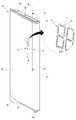
도 2는 본 발명의 실시 예에 의한 냉장고 도어의 사시도이다.
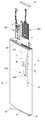
도 3은 상기 냉장고 도어의 디스플레이 어셈블리의 장착 구조를 보인 분해 사시도이다.
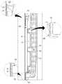
도 4는 상기 냉장고 도어의 전면 패널이 분리된 분해 사시도이다.
도 5는 본 발명의 실시 예에 의한 터치센서 어셈블리와 커버 디스플레이, 디스플레이 어셈블리, 프레임 디스플레이 및 프레임의 결합 구조를 보인 분해 사시도이다.
도 6은 도 3의 6-6' 단면도이다.
도 7은 도 3의 7-7' 단면도이다.
도 8은 센서 피시비와 디스플레이 피시비의 연결을 보인 블럭도이다.
도 9는 상기 커버 디스플레이와 프레임 디스플레이의 결합 구조를 보인 사시도이다.
도 10은 상기 커버 디스플레이와 터치센서 어셈블리의 결합 구조를 보인 분해 사시도이다.
도 11은 상기 터치센서 어셈블리가 장착된 상기 커버 디스플레이를 후방에서 본 사시도이다.
도 12는 도 2의 12-12' 절결 사시도이다.
도 13은 도 12의 A부 확대 단면도이다.
도 14는 본 발명의 실시 예에 의한 터치센서 어셈블리를 전방에서 바라본 분해 사시도이다.
도 15는 상기 터치센서 어셈블리를 후방에서 바라본 분해 사시도이다.
도 16은 상기 터치센서 어셈블리의 종단면도이다.
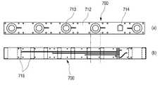
도 17은 상기 터치센서 어셈블리의 요부 구성인 센서 피시비의 평면도와 배면도이다.
도 18은 상기 터치센서 어셈블리의 요부 구성인 스페이서의 평면도이다.
도 19는 상기 터치센서 어셈블리의 요부 구성인 컨덕티브 포일의 평면도이다.
도 20은 상기 터치센서 어셈블리의 요부 구성인 터치 부스터의 배면 사시도이다.
도 21은 도 2의 21-21' 절결 사시도이다.
도 22는 도 21의 B부 확대 단면도이다.
도 23은 상기 터치센서 어셈블리가 장착된 상태의 횡단면도이다.
도 24는 상기 터치센서 어셈블리의 요부 구성인 탄성부재의 다른 형상을 보인 사시도이다.
도 25는 상기 터치센서 어셈블리의 요부 구성인 탄성부재의 또 다른 형상을 보인 사시도이다.
도 26은 본 발명의 실시 예에 의한 냉장고 도어의 제조 방법을 순차적으로 보인 도면이다.
도 27은 상기 스페이서와 컨덕티브 포일이 접착되는 방법을 보인 도면이다.
도 28은 상기 커버 디스플레이를 고정 및 부착 지그를 이용하여 장착하는 모습을 상방에서 바라본 평면도이다.
도 29는 도 28을 측방에서 바라본 측면도이다.
도 30은 상기 커버 디스플레이를 비전방식으로 장착하는 모습을 보인 사시도이다.
도 31은 상기 커버 디스플레이를 관통 지그를 이용하여 장착하는 모습을 보인 사시도이다.
도 32는 상기 관통 지그가 전면 패널과 커버 디스플레이를 관통하는 모습을 보인 단면도이다.
도 33은 상기 디스플레이 어셈블리의 장착 과정을 보인 분해 사시도이다.
도 34는 본 발명의 다른 실시 예에 의한 커버 디스플레이와 센서 하우징의 구조를 보인 분해 사시도이다.
도 35는 본 발명의 실시 예에 의한 터치센서 어셈블리가 다른 형태의 냉장고 도어에 장착되는 구조를 보인 분해 사시도이다.
도 36은 본 발명의 실시 예에 의한 터치센서 어셈블리가 공기조화기에 장착되는 구조를 보인 분해 사시도이다.
도 37은 본 발명의 실시 예에 의한 터치센서 어셈블리가 세탁기에 장착되는 구조를 보인 분해 사시도이다.
도 38은 본 발명의 실시 예에 의한 터치센서 어셈블리가 식기세척기에 장착되는 구조를 보인 분해 사시도이다.
도 39는 본 발명의 실시 예에 의한 터치센서 어셈블리가 조리기기에 장착되는 구조를 보인 분해 사시도이다.1 is a front view of a refrigerator according to an embodiment of the present invention.
2 is a perspective view of a refrigerator door according to an embodiment of the present invention.
3 is an exploded perspective view showing a mounting structure of the display assembly of the refrigerator door.
FIG. 4 is an exploded perspective view illustrating a front panel of the refrigerator door. FIG.
5 is an exploded perspective view showing a combined structure of a touch sensor assembly, a cover display, a display assembly, a frame display, and a frame according to an embodiment of the present invention.
6 is a cross-sectional view taken along line 6-6 'of FIG.
7 is a cross-sectional view taken along line 7-7 'of Fig.
8 is a block diagram showing a connection between a sensor file ratio and a display file ratio.
9 is a perspective view showing a combined structure of the cover display and the frame display.
10 is an exploded perspective view showing a combined structure of the cover display and the touch sensor assembly.
11 is a perspective view of the cover display with the touch sensor assembly as viewed from the rear.
12 is a sectional view taken along line 12-12 'of FIG.
13 is an enlarged cross-sectional view of part A of Fig.
14 is an exploded perspective view of a touch sensor assembly according to an embodiment of the present invention viewed from the front.
15 is an exploded perspective view of the touch sensor assembly viewed from the rear.
16 is a longitudinal sectional view of the touch sensor assembly.
FIG. 17 is a plan view and a rear view of a sensor package, which is a main constituent of the touch sensor assembly.
18 is a plan view of a spacer which is a main constituent of the touch sensor assembly.
FIG. 19 is a plan view of a conductive foil, which is the essential part of the touch sensor assembly.
20 is a rear perspective view of the touch booster, which is the essential part of the touch sensor assembly.
21 is a cutaway oblique view 21-21 'of FIG.
22 is an enlarged cross-sectional view of part B in Fig.
23 is a cross-sectional view of the state where the touch sensor assembly is mounted.
24 is a perspective view showing another shape of an elastic member which is a main constituent of the touch sensor assembly.
25 is a perspective view showing another shape of an elastic member which is a main constituent of the touch sensor assembly.
FIG. 26 is a view sequentially showing a method of manufacturing a refrigerator door according to an embodiment of the present invention.
27 is a view showing a method of bonding the spacer and the conductive foil.
28 is a plan view of the cover display from above when the cover is mounted using a fixing and attaching jig.
FIG. 29 is a side view of the side view of FIG. 28; FIG.
30 is a perspective view showing a state in which the cover display is mounted in a vision-type manner.
31 is a perspective view showing a state in which the cover display is mounted using a through jig.
32 is a cross-sectional view showing the through jig passing through the front panel and the cover display.
33 is an exploded perspective view showing the mounting process of the display assembly.
34 is an exploded perspective view showing a structure of a cover display and a sensor housing according to another embodiment of the present invention.
FIG. 35 is an exploded perspective view showing a structure in which the touch sensor assembly according to the embodiment of the present invention is mounted on another type of refrigerator door.
FIG. 36 is an exploded perspective view showing a structure in which the touch sensor assembly according to the embodiment of the present invention is mounted to the air conditioner.
37 is an exploded perspective view showing a structure in which a touch sensor assembly according to an embodiment of the present invention is mounted on a washing machine.
38 is an exploded perspective view showing a structure in which the touch sensor assembly according to the embodiment of the present invention is mounted on a dishwasher.
FIG. 39 is an exploded perspective view showing a structure in which a touch sensor assembly according to an embodiment of the present invention is mounted on a cooking device.
이하에서는 본 발명의 구체적인 실시 예를 도면과 함께 상세히 설명하도록 한다. 그러나 본 발명은 본 발명의 사상이 제시되는 실시 예에 제한된다고 할 수 없으며, 또 다른 구성요소의 추가, 변경, 삭제 등에 의해서 퇴보적인 다른 발명이나 본 발명의 사상범위 내에 포함되는 다른 실시 예를 용이하게 제안할 수 있다.Hereinafter, specific embodiments of the present invention will be described in detail with reference to the drawings. However, it should be understood that the present invention is not limited to the embodiment shown in the drawings, and that other embodiments falling within the spirit and scope of the present invention may be easily devised by adding, .
특히, 본 발명의 실시 예는 설명과 이해의 편의를 위해 사이드바이사이드(side by side)타입 냉장고를 예를 들어 설명하기로 하며, 본 발명은 모든 타입의 냉장고는 물론 터치센서 어셈블리가 구비될 수 있는 가전기기에 적용 가능함을 미리 밝혀둔다.In particular, embodiments of the present invention will be described by way of a side by side refrigerator for convenience of explanation and understanding. The present invention can be applied to all kinds of refrigerators as well as a touch sensor assembly It is possible to apply this method to a home appliance.
도 1은 본 발명의 실시 예에 의한 냉장고의 정면도이다.1 is a front view of a refrigerator according to an embodiment of the present invention.
도면에 도시된 것과 같이, 본 발명의 실시 예에 의한 냉장고(1)는 저장공간을 형성하는 캐비닛과 상기 캐비닛에 장착되어 저장공간을 개폐하는 냉장고 도어(10)에 의해 외형이 형성될 수 있다.As shown in the figure, the
상기 저장공간은 좌우 양측 및/또는 상하로 구획될 수 있으며, 상기 저장공간의 개구된 전면에는 각각의 공간을 개폐하는 다수의 냉장고 도어(10)가 구비될 수 있다. 상기 냉장고 도어(10)는 슬라이딩 또는 회전 방식으로 상기 저장공간을 개폐할 수 있도록 구성되며, 닫힌 상태에서는 상기 냉장고(1)의 전면 외관을 형성할 수 있도록 구성된다.The storage space may be divided into left and right sides and / or upper and lower sides, and a plurality of
그리고, 상기 다수의 냉장고 도어(10) 중 일측의 냉장고 도어(10)에는 사용자의 조작 및 식별이 용이한 높이에 디스플레이 창(11)과 터치 조작부(12)가 제공된다.A
상기 디스플레이 창(11)은 냉장고(1)의 작동 상태를 외부로 나타내기 위한 것으로 상기 냉장고 도어(10)의 내부에서 조사되는 빛이 투과되면서 기호 또는 숫자 등을 표현하여 사용자가 외부에서 이를 확인할 수 있도록 한다.The
상기 터치 조작부(12)는 사용자가 냉장고(1)의 동작을 위해 터치 조작하는 부분으로 상기 냉장고 도어(10)의 전면 일부 영역에 제공되며, 누름 조작이 감지될 수 있는 부분이 인쇄 또는 에칭과 같은 펴면 가공 또는 빛의 투과 등 다양한 방법에 의해 정의될 수 있다.The
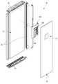
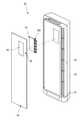
도 2는 본 발명의 실시 예에 의한 냉장고 도어의 사시도이다. 그리고, 도 3은 상기 냉장고 도어의 디스플레이 어셈블리의 장착 구조를 보인 분해 사시도이다. 그리고, 도 4는 상기 냉장고 도어의 전면 패널이 분리된 분해 사시도이다.2 is a perspective view of a refrigerator door according to an embodiment of the present invention. 3 is an exploded perspective view showing a mounting structure of the display assembly of the refrigerator door. 4 is an exploded perspective view illustrating a front panel of the refrigerator door.
도면에 도시된 것과 같이, 상기 냉장고 도어(10)는 전체적으로 외관을 형성하는 전면 패널(20)과, 상기 전면 패널(20)의 상단과 하단에 구비되는 데코부재(40,43) 그리고, 상기 냉장고 도어(10)의 후면 외관을 형성하는 도어 라이너(30)에 의해 전체적인 외관이 형성된다.As shown in the figure, the
이를 보다 상세하게 살펴보면, 상기 전면 패널(20)은 상기 냉장고 도어(10)의 전면 외관을 형성하는 것으로, 판상의 스테인레스 스틸 소재로 형성될 수 있다. 그리고, 상기 전면 패널(20)은 상기 냉장고 도어(10)의 외관 적어도 일부를 형성하는 구성으로 냉장고가 아닌 다른 가전 제품에서는 외장부재로 표현될 수 있다.In more detail, the
상기 전면 패널(20)은 스테인레스 스틸이 아닌 금속 또는 금속과 같은 질감을 가지도록 하는 소재에 의해 형성될 수도 있으며, 필요에 따라서 유리 또는 플라스틱 소재로 형성될 수 있다.The
상기 전면 패널(20)은 상기 냉장고 도어(10)의 전면은 물론 필요에 따라 상기 냉장고 도어(10)의 측면 일부도 형성될 수 있으며, 상기 전면 패널(20)의 표면에는 지문방지 처리 또는 헤어라인 가공이 더 이루어질 수 있다.The
한편, 상기 디스플레이 창(11)은 상기 전면 패널(20)의 일부 영역에 배치되는 다수의 제 1 관통구(21)에 의해 정의될 수 있다. 상기 디스플레이 창(11)은 숫자나 기호를 나타낼 수 있도록 일정한 배치로 천공된 다수의 제 1 관통구(21)의 집합으로 구성될 수 있다. 예컨데 다수의 상기 제 1 관통구(21)의 집합은 7세그먼트의 형상으로 배치될 수 있으며, 상기 냉장고(1)의 상태를 나타낼 수 있는 특정 기호나 문양의 형상으로 형성될 수도 있다.The
상기 디스플레이 창(11)은 아래에서 설명할 제 2 관통구(220) 및 제 3 관통구(321)의 배치와 대응하도록 형성되어 디스플레이 어셈블리(300)의 엘이디(313)에서 조사되는 빛이 투과될 수 있도록 형성된다. 상기 제 1 관통구(21)는 레이저 가공이나, 에칭 등을 통해서 미세한 크기로 형성될 수 있으며, 빛이 통과되지 않는 상태에서는 외부에서 쉽게 확인할 수 없는 크기로 형성될 수 있다.The
한편, 상기 제 1 관통구(21)의 내부에는 실링부재(22)가 채워질 수 있다. 상기 실링부재(22)는 상기 제 1 관통구(21)가 이물질에 의해 막히는 것을 방지하게 된다. 상기 실링부재(22)는 실리콘 또는 에폭시 소재로 형성되어 상기 제 1 관통구(21)를 막되 빛의 투과가 가능한 소재로 형성될 수 있다. 그리고, 상기 제 1 관통구(21)의 내측이 상기 실링부재(22)에 의해 채워짐으로써 상기 제 1 관통구(21)의 가공면이 부식되는 것을 방지할 수도 있게 된다.Meanwhile, the sealing
상기 실링부재(22)는 별도의 공정을 통해서 상기 제 1 관통구(21)의 내측을 채울 수 있도록 할 수 있으며, 필요에 따라서 상기 전면 패널(20)의 표면 코팅 과정에서 상기 제 1 관통구(21)를 채우거나, 시트의 형태로 부착되어 다수의 상기 제 1 관통구가 동시에 막힐 수 있도록 구성될 수 있다. 즉, 상기 전면 패널(20)의 내 지문 코팅액 및/또는 확산시트가 실링부재(22)의 역할을 할 수도 있다.The sealing
상기 터치 조작부(12)는 사용자가 터치 조작을 할 수 있도록 표시된 부분으로, 사용자가 상기 터치 조작부(12)를 터치하게 되었을 때 터치센서 어셈블리(500)에서 이를 감지할 수 있는 영역을 표시하게 된다. 상기 터치 조작부(12)는 에칭이나 인쇄 또는 기타 표면 가공을 통해서 상기 전면 패널(20)의 전면에 표시될 수 있으며, 외부에서 볼 때 두드러지지 않는 형태로 표현되어 상기 전면 패널(20) 전체의 질감이 외관을 형성하는 것으로 보일 수 있도록 한다.The
상기 도어 라이너(30)는 상기 전면 패널(20)과 결합되며, 상기 저장공간의 내측을 향하는 면을 형성하게 된다. 상기 도어 라이너(30)는 플라스틱 소재로 사출 성형되며, 둘레를 따라서 가스켓이 배치되거나 바스켓 등이 장착될 수 있는 구조를 제공할 수 있다. 그리고, 상기 도어 라이너(30)는 상기 전면 패널(20)과의 결합시 상기 도어 라이너(30)와 전면 패널(20) 사이에 공간을 형성하게 되며, 이 공간에는 단열재(24)를 형성하는 발포액이 충진될 수 있다.The
상기 전면 패널(20)의 후면에는 프레임(100)이 부착될 수 있다. 상기 프레임(100)은 상기 냉장고 도어(10)의 내부에서 발포액이 충진되지 않는 별도의 공간을 제공할 수 있도록 형성되며, 커버 디스플레이(200)와, 디스플레이 어셈블리(300), 터치센서 어셈블리(500), 프레임 디스플레이(400) 등이 수용되는 공간을 제공하게 된다.A
상기 데코부재(40,43)는 상기 냉장고 도어(10)의 상부와 하부의 외관을 형성하는 것으로, 상기 전면 패널(20)과 도어 라이너(30)의 결합에 의해 형성되는 개구된 상기 냉장고 도어(10)의 상단과 하단을 차폐할 수 있도록 구성된다.The
상기 데코부재(40,43) 중 상기 냉장고 도어(10) 상부의 데코부재(40)에는 삽입구(41)와 상기 삽입구(41)를 개폐하는 삽입구 커버(42)가 구비된다. 상기 삽입구(41)는 상기 데코부재(40)를 관통하며 상기 프레임(100)이 형성하는 공간과 연통된다. 따라서, 상기 삽입구(41)를 통해서 사용자는 상기 디스플레이 어셈블리(300)가 조립된 상태의 프레임 디스플레이(400)의 삽입이 가능하게 된다. 이를 위해서 상기 삽입구(41)는 상기 프레임 디스플레이(400)가 삽입 가능한 크기로 형성되며, 상기 커버 디스플레이(200)의 수직 상방에 위치될 수 있다.The
한편, 상세하게 도시되지는 않았지만 상기 데코부재(40)의 일측에는 상기 냉장고 도어(10)의 회전 축이 되는 힌지가 장착되는 힌지 홀(미도시)이 형성된다. 그리고, 상기 힌지 홀을 통해서 상기 프레임(100)의 내측에서 안내되는 전선이 출입되어 상기 캐비닛의 전원부와 연결될 수 있는 구조를 가지게 된다.Meanwhile, although not shown in detail, a hinge hole (not shown) is formed at one side of the
상기 냉장고 도어(10) 하부의 데코부재(43)에는 도어 핸들(44)이 제공될 수 있다. 상기 도어 핸들(44)은 포켓 형태로 함몰되어 상기 냉장고 도어(10)를 회전 조작할 수 있도록 구성된다. 그리고, 냉장고 도어(10) 하부의 데코부재(43)에는 상기 냉장고 도어(10)의 개폐 조작을 위한 레버(45)가 더 구비되며, 상기 레버(45)의 조작에 의해 래치 어셈블리(31)가 구동되어 상기 냉장고 도어(10)의 개방 또는 닫힘 상태의 유지를 선택 가능하게 된다.A door handle (44) may be provided on the decor member (43) under the refrigerator door (10). The
상기 전면 패널(20)의 후면에는 커버 디스플레이(200)가 부착된다. 상기 커버 디스플레이(200)는 엘이디(313)가 실장된 디스플레이 어셈블리(300)의 장착을 가이드 하기 위한 것으로, 양면테이프 또는 프라이머가 도포되어 형성되는 접착부재(25)에 의해 상기 전면 패널(20)의 후면에 부착될 수 있도록 구성된다.A
상기 커버 디스플레이(200)의 일측에는 사용자의 상기 전면 패널(20)의 누름 조작을 감지할 수 있는 터치센서 어셈블리(500)가 장착된다. 상기 커버 디스플레이(200)는 상기 터치센서 어셈블리(500)와 결합된 상태에서 상기 전면 패널(20)에 부착될 수 있는 구조를 가진다.A
상기 커버 디스플레이(200)는 상기 디스플레이 창(11)과 상기 커버 디스플레이(200)에 형성된 제 2 관통구(220)가 서로 일치하는 위치에 부착될 수 있다. 그리고, 상기 커버 디스플레이(200)는 부착된 상태에서 상기 프레임(100)의 내측에 수용된다.The
그리고, 상기 디스플레이 어셈블리(300)는 상기 프레임 디스플레이(400)에 장착된 상태로 상기 삽입구(41)를 통해서 상기 프레임(100) 내부의 공간으로 삽입된다. 상기 프레임 디스플레이(400)가 완전히 삽입되면, 상기 디스플레이 어셈블리(300)는 상기 커버 디스플레이(200)의 내측에 위치되며, 상기 엘이디(313)에서 조사되는 빛은 상기 커버 디스플레이(200)와 디스플레이 창(11)을 지나서 외부로 조사될 수 있게 된다.The
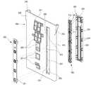
도 5는 본 발명의 실시 예에 의한 터치센서 어셈블리와 커버 디스플레이, 디스플레이 어셈블리, 프레임 디스플레이 및 프레임의 결합 구조를 보인 분해 사시도이다. 그리고, 도 6은 도 3의 6-6' 단면도이다. 그리고, 도 7은 도 3의 7-7' 단면도이다. 그리고, 도 8은 센서 피시비와 디스플레이 피시비의 연결을 보인 블럭도이다.5 is an exploded perspective view showing a combined structure of a touch sensor assembly, a cover display, a display assembly, a frame display, and a frame according to an embodiment of the present invention. 6 is a cross-sectional view taken along line 6-6 'of FIG. 7 is a cross-sectional view taken along line 7-7 'of Fig. 8 is a block diagram showing a connection between the sensor file ratio and the display file ratio.
도면에 도시된 것과 같이, 상기 프레임(100)은 전면과 상면이 개구되도록 형성되며, 상기 전면 패널(20)에 부착되었을 때 상면이 개구된 공간(110)을 형성할 수 있도록 형성된다. 이를 위해 상기 프레임(100)의 상단을 제외한 둘레가 상기 전면 패널(20)을 향하여 절곡되며, 그 단부가 다시 외측으로 절곡되어 프레임 접착부(120)를 형성하게 된다. 상기 프레임 접착부(120)에는 양면테이프 또는 접착제로 이루어진 접착부재(25)가 제공되어 상기 프레임(100)이 상기 전면 패널(20)의 후면에 부착될 수 있게 된다.As shown in the drawing, the
상기 프레임(100)은 상기 전면 패널(20)에 부착된 상태에서 상단이 상기 데코부재(40)의 하면과 접하게 된다. 따라서, 상기 프레임(100)의 개구된 상면이 상기 삽입구(41)와 연통될 수 있으며, 상기 냉장고 도어(10)의 내부에서 독립된 공간을 형성하게 된다.The upper end of the
따라서, 상기 냉장고 도어(10)의 내부에 상기 단열재(24)의 형성을 위한 발포액의 주입시에도 상기 프레임(100) 내부의 공간으로 발포액이 유입되지 않고 보호될 수 있게 된다. 그리고, 상기 프레임(100)의 후면에는 다수의 보강 리브(130)가 가로 세로 방향으로 교차되도록 형성되며, 상기 단열재(24)의 성형을 위한 고압의 발포액 충진시에도 상기 보강 리브(130)에 의해 변형되지 않고 상기 프레임(100) 내부의 공간을 유지할 수 있게 된다.Therefore, even when the foamed liquid for forming the
그리고, 상기 프레임(100)의 상부 좌우 양측단에는 서포트 플레이트(141)가 안착되는 플레이트 지지부(140)가 형성된다. 상기 서포트 플레이트(141)는 상기 커버 디스플레이(200)가 장착된 상태에서 상기 커버 디스플레이(200) 상방에 해당하는 상기 프레임(100)의 상부 공간의 영역에 설치되어 상기 전면 패널(20)을 후방에서 지지하도록 구성된다. 따라서, 상기 전면 패널(20)의 대응하는 부분이 일렁대는 것을 방지함은 물론 외부 충격에 의해 전면 패널(20)이 변형되는 것을 방지할 수 있게 된다.A
상기 플레이트 지지부(140)는 단차지게 형성되어 상기 서포트 플레이트(141)의 양단을 지지할 수 있도록 구성된다. 그리고, 상기 서포트 플레이트(141)는 상기 프레임(100)이 상기 전면 패널(20)에 부착된 상태에서 상기 플레이트 지지부(140)와 상기 전면 패널(20)의 사이 공간으로 슬라이딩 삽입될 수 있다. 물론, 상기 서포트 플레이트(141)는 상기 플레이트 지지부(140)에 양단이 고정된 상태로 상기 프레임(100)의 부착시 함께 상기 전면 패널(20)의 배면에 부착될 수도 있다.The
상기 프레임(100)의 측면 상부에는 전선 출입구(150)가 형성된다. 상기 전선 출입구(150)는 상기 프레임(100)의 내부에 구비되는 전장 부품들과 상기 캐비닛 상의 전원부가 연결될 수 있도록 하는 전선이 출입되는 통로를 형성하게 된다. 상기 전선 출입구(150)는 상기 냉장고 도어(10)의 힌지와 가까운 측면의 상부에 형성되어 상기 냉장고 도어(10)의 힌지 홀과 가까운 거리에 배치될 수 있다. 그리고, 상기 냉장고 도어(10)의 내측에 발포액을 주입할 때에는 마감 처리되어 상기 프레임(100)의 내부로 발포액이 유입되는 것을 방지하게 된다.A wire entry /
그리고, 상기 프레임(100)의 좌우 양측에는 구속홈(160)이 형성된다. 상기 구속홈(160)은 상기 커버 디스플레이(200)의 좌우 양측단에서 측방으로 돌출된 구속부(230)가 삽입되도록 형성된다. 즉, 상기 구속홈(160)은 외측 방향으로 함몰되며 상기 구속부(230)와 대응하는 형상으로 형성되어, 상기 커버 디스플레이(200)가 유동되지 않고 정확한 위치를 유지할 수 있도록 한다.At both right and left sides of the
상기 구속홈(160) 하부의 상기 커버 디스플레이(200)가 위치되는 부분에는 상기 커버 디스플레이(200)를 지지하는 커버 지지부(170)가 형성된다. 상기 커버 지지부(170)는 상기 프레임(100)의 좌우 양측면에서 돌출되며, 상기 커버 디스플레이(200)의 좌우 양측단을 후방에서 눌러 지지할 수 있도록 한다.A
따라서, 상기 커버 디스플레이(200)가 상기 전면 패널(20)의 후면에 부착된 상태에서, 상기 프레임(100)이 상기 전면 패널(20)에 부착되고 발포액이 상기 냉장고 도어(10)의 내부에 주입되면, 상기 커버 지지부(170)는 상기 커버 디스플레이(200)를 전방으로 밀어서 상기 커버 디스플레이(200)가 상기 전면 패널(20)에 부착된 상태를 유지할 수 있도록 한다. 특히, 상기 커버 디스플레이(200)를 상기 전면 패널(20)에 부착시키는 상기 접착부재(25)가 경화되어 기능을 상실하게 되는 경우에도 상기 커버 지지부(170)는 상기 커버 디스플레이(200)를 가압하여 상기 전면 패널(20)과 상기 커버 디스플레이(200)가 밀착된 상태를 유지할 수 있도록 한다.Therefore, when the
상기 커버 지지부(170)는 다수개가 일정 간격으로 상하로 배치되어 상기 커버 디스플레이(200) 전체를 고르게 눌러서 지지할 수 있도록 한다. 그리고, 상기 커버 디스플레이(200)와 인접하는 커버 지지부(170)의 전면에는 전방으로 돌출되는 돌출부(171)가 더 형성된다. 상기 돌출부(171)는 가로방향으로 길게 형성되는 리브 형상 또는 돌기 형상으로 형성되며, 상기 커버 디스플레이(200)와 선 또는 점 접촉될 수 있도록 한다. 따라서, 상기 커버 디스플레이(200)와 상기 커버 지지부(170)의 접촉면이 고르지 않더라도 상기 커버 디스플레이(200)가 기울어지지 않도록 하며, 각각의 상기 커버 지지부(170)는 상기 커버 디스플레이(200)에 고른 압력을 전달할 수 있게 된다.A plurality of the
상기 커버 디스플레이(200)는 판상의 플라스틱 소재로 형성되며, 상기 전면 패널(20)에 부착된 상태에서 상기 프레임(100)의 내측에 수용 가능하게 형성된다. 그리고, 상기 커버 디스플레이(200)의 좌우 양측단의 상부에는 외측으로 돌출되어 상기 구속홈(160)에 삽입되는 구속부(230)가 형성된다.The
한편, 상기 커버 디스플레이(200)에는 상기 터치센서 어셈블리(500)가 장착되는 수용부(210)가 형성된다. 그리고, 상기 커버 디스플레이(200)에는 상기 디스플레이 창(11)과 대응하는 위치에 다수의 제 2 관통구(220)가 형성된다.Meanwhile, the
상기 디스플레이 어셈블리(300)는 상기 엘이디(313)가 실장된 디스플레이 피시비(310)와 상기 디스플레이 피시비(310)의 전면에 배치되는 리플렉터(320)를 포함하여 구성될 수 있다.The
상기 디스플레이 피시비(310)에는 상기 엘이디(313)의 구동을 위한 제어부가 포함되며, 상기 터치센서 어셈블리(500)의 구동을 위한 센서 제어부가 실장된다. 즉, 상기 센서 제어부(330)는 상기 터치센서 어셈블리(500)를 통해서 감지된 상기 전면 패널(20)의 조작 신호를 상기 디스플레이 피시비(310) 상에서 처리하게 되는 것이다. 이를 위해 상기 터치센서 어셈블리(500)의 센서 피시비(700)와 디스플레이 피시비(310)는 케이블 커넥터(600)로 연결될 수 있게 된다.The
상기 케이블 커넥터(600)는 센서 피시비(700)와 연결되는 제 1 케이블 커넥터(610)와, 상기 디스플레이 피시비(310)와 연결되는 제 2 케이블 커넥터(620)로 구성되며, 상기 제 1 케이블 커넥터(610)와 제 2 케이블 커넥터(620)는 각각 상기 센서 피시비(700)와 디스플레이 피시비(310)에 연결된 상태에서 상기 냉장고 도어(10)에 상기 디스플레이 어셈블리(300)가 장착되는 과정에서 서로 연결될 수 있도록 구성된다.The
이때, 상기 케이블 커넥터(600)의 전체 길이는 상기 터치센서 어셈블리(500)에서 상기 삽입구(41)까지의 거리보다 더 길게 형성되어 상기 터치센서 어셈블리(500)가 상기 커버 디스플레이(200)에 장착된 상태에서 상기 삽입구(41)의 외측에서 서로 연결된 후 상기 디스플레이 어셈블리(300)를 장착할 수 있도록 형성된다.The entire length of the
한편, 상기 제 2 케이블 커넥터(620)와 연결되는 디스플레이 단자(311)는 상기 디스플레이 피시비(310)의 상단 좌측(도 5에서 볼 때)에 배치된다. 이는 상기 디스플레이 단자(311)가 상기 터치센서 어셈블리(500)와 가능한 먼 위치에 위치되도록 하여 사용시 발생되는 정전기에 의한 영향을 최소화하기 위함이다.The
그리고, 상기 디스플레이 피시비(310)의 전면에는 상기 엘이디(313)의 빛이 상기 제 1 관통구(21)로 향하도록 가이드하는 리플렉터(320)가 구비된다. 상기 리플렉터(320)는 상기 엘이디(313)의 빛을 안내할 뿐만 아니라 상기 리플렉터(320)의 두께만큼 상기 디스플레이 피시비(310) 및 상기 디스플레이 단자(311)가 상기 전면 패널(20)로부터 이격될 수 있도록 하여 정전기로부터 상기 디스플레이 피시비(310)를 보호할 수 있도록 한다.A
특히, 상기 전면 패널(20)이 스테인레스 스틸 소재로 형성될 뿐만 아니라 디스플레이 창(11)에 인접하게 상기 디스플레이 어셈블리(300)가 배치되어야 하는 구조의 특성상 사용 중 발생되는 정전기에 취약할 수 있으나, 상기 리플렉터(320)에 의해 상기 디스플레이 피시비(310)가 구조적으로 상기 전면 패널(20)과 이격되면서도 빛의 전달이 우수하도록 하여 정전기로부터 상기 디스플레이 피시비(310)를 보호할 수 있게 된다.Particularly, the
상기 리플렉터(320)에는 상기 엘이디(313)의 배치와 대응하며, 상기 제 2 관통구(220) 및 제 1 관통구(21)와 연통될 수 있는 제 3 관통구(321)가 형성된다. 상기 디스플레이 어셈블리(300)가 장착된 상태에서 상기 프레임 디스플레이(400)가 상기 커버 디스플레이(200)에 장착되며, 상기 제 1 관통구(21)와 제 2 관통구(220) 및 제 3 관통구(321)는 모두 밀착되고 서로 연통하는 구조를 가지며, 상기 엘이디(313)에서 조사되는 빛이 상기 디스플레이 창(11)을 통해서 외부로 조사될 수 있도록 한다.The
한편, 상기 디스플레이 피시비(310)의 배면에는 음향 출력장치(340)가 구비된다. 상기 음향 출력장치(340)는 상기 냉장고(1)의 동작 상태를 소리로 나타내기 위한 것으로 스피커, 버저(buzzer)가 사용될 수 있다. 상기 음향 출력장치(340)는 상기 프레임 디스플레이(400)의 프레임 홀(412)과 대응하는 위치에 위치될 수 있다. 따라서, 상기 음향 출력장치(340)에서 출력되는 소리는 상기 냉장고 도어(10) 외측의 사용자에게 전달되어 상기 냉장고(1)의 동작 상태를 표현할 수 있게 된다.On the other hand, a
한편, 상기 프레임 디스플레이(400)는 상기 디스플레이 피시비(310)가 장착되는 것으로, 상기 디스플레이 피시비(310)가 안착 가능한 판상으로 형성된다. 그리고, 상기 프레임 디스플레이(400)의 둘레를 따라서 전방으로 절곡되는 테두리(410)가 형성되어 상기 디스플레이 피시비(310)가 수용되는 공간을 형성하게 된다. 그리고, 상기 프레임 디스플레이(400)의 좌우 양측단에는 좌우 양측으로 절곡되는 슬라이딩 삽입부(415)가 형성된다. 상기 슬라이딩 삽입부(415)는 상기 커버 디스플레이(200)에 형성되는 가이드 레일(240)의 내측으로 삽입될 수 있도록 형성된다. 따라서, 상기 프레임 디스플레이(400)는 상기 슬라이딩 삽입부(415)에 의해 상기 커버 디스플레이(200)에 장착될 수 있게 된다.Meanwhile, the
상기 프레임 디스플레이(400)의 전면 전체에는 가로 및 세로로 일정 간격으로 형성되어 격자형상을 형성하는 보강 리브(411)가 더 형성된다. 그리고, 상기 음향 출력장치(340)와 대응하는 일측에는 프레임 홀(412)이 형성된다.A reinforcing
그리고, 상기 프레임 디스플레이(400) 상단에는 프레임 절개부(414)가 형성된다. 상기 프레임 절개부(414)는 상기 디스플레이 단자(311)와 대응하는 위치에서 대응하는 크기로 절개되어 상기 디스플레이 단자(311)와 상기 프레임 디스플레이(400)가 간섭되는 것을 방지하게 된다.A
그리고, 상기 프레임 디스플레이(400)에는 상기 디스플레이 피시비(310)를 고정하기 위한 스크류(312)가 체결되는 보스(413)가 형성된다. 상기 보스(413)는 상기 스크류(312)와의 결합은 물론 상기 디스플레이 피시비(310)를 하방에서 지지하게 된다.The
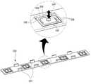
한편, 상기 프레임 디스플레이(400) 상단의 중앙부에는 상방으로 연장 형성되는 프레임 핸들(420)이 구비된다. 상기 프레임 핸들(420)은 상기 프레임 디스플레이(400)가 상기 커버 디스플레이(200)에 결합될 때 사용자가 쥐고 조작하는 것으로 소정의 길이를 가지도록 형성된다.Meanwhile, a
상기 프레임 핸들(420)은 상기 프레임 디스플레이(400)에서 연장되는 제 1 수직부(421)와, 상기 제 1 수직부(421)의 상단에서 후방으로 경사지게 연장되는 경사부(422), 그리고 상기 경사부(422)의 상단에서 다시 상방으로 연장되는 제 2 수직부(423)로 구성된다. 상기 제 1 수직부(421)와 제 2 수직부(423)는 서로 평행하게 연장되되 상기 경사부(422)에 의해 연결된다. 그리고, 상기 제 2 수직부(423)의 상단에는 사용자가 잡을 수 있는 그립부(424)가 가로 방향으로 연장 형성된다.The frame handle 420 includes a first
따라서, 사용자는 상기 프레임 디스플레이(400)를 삽입시 상기 그립부(424)를 쥐고 상기 프레임 디스플레이(400)의 하단부터 상기 삽입구(41) 내측으로 삽입하게 된다. 그리고, 상기 프레임 디스플레이(400)를 하방으로 삽입하게 될수록 상기 프레임 핸들(420)의 구조에 의해 상기 프레임 디스플레이(400)는 상기 커버 디스플레이(200)의 후면에 용이하게 밀착될 수 있다.Accordingly, the user inserts the
상기 프레임 디스플레이(400)가 완전히 삽입된 상태에서 상기 삽입구 커버(42)를 닫게 되면, 상기 삽입구 커버(42)는 상기 그립부(424)와 접하게 된다. 도시되지는 않았지만, 상기 삽입구 커버(42)의 하면에는 상기 그립부(424)와 대응하는 형상으로 성형된 핸들 결합부가 형성되어, 상기 삽입구 커버(42)가 닫히게 될 때 상기 프레임 핸들(420)의 상단이 상기 핸들 결합부에 결합되어 고정된 상태를 유지할 수 있게 된다.When the
도 9는 상기 커버 디스플레이와 프레임 디스플레이의 결합 구조를 보인 사시도이다. 그리고, 도 10은 상기 커버 디스플레이와 터치센서 어셈블리의 결합 구조를 보인 분해 사시도이다. 그리고, 도 11은 상기 터치센서 어셈블리가 장착된 상기 커버 디스플레이를 후방에서 본 사시도이다.9 is a perspective view showing a combined structure of the cover display and the frame display. FIG. 10 is an exploded perspective view showing a combined structure of the cover display and the touch sensor assembly. 11 is a perspective view of the cover display with the touch sensor assembly as viewed from the rear.
도면에 도시된 것과 같이, 상기 커버 디스플레이(200)의 좌우 양측단에는 가이드 레일(240)이 형성된다. 상기 가이드 레일(240)은 상기 커버 디스플레이(200)의 양단이 절곡되어 상기 슬라이딩 삽입부(415)가 상기 가이드 레일(240)을 따라 삽입될 수 있도록 형성된다.As shown in the figure,
상기 가이드 레일(240)은 상단이 넓게 형성되어, 상기 슬라이딩 삽입부(415)가 용이하게 삽입될 수 있게 된다. 상기 가이드 레일(240)의 내측면은 경사지게 형성되어 상기 프레임 디스플레이(400)가 삽입될수록 상기 프레임 디스플레이(400)에 장착된 상기 디스플레이 어셈블리(300)가 상기 커버 디스플레이(200)를 향하여 밀착되도록 구성될 수 있다.The
그리고, 도시되지는 않았지만, 상기 프레임 디스플레이(400)가 완전히 삽입된 상태에서는 상기 슬라이딩 삽입부(415)가 상기 가이드 레일(240)의 내측에서 고정될 수 있으며, 상기 리플렉터(320)가 상기 커버 디스플레이(200)의 후면에 완전히 밀착될 수 있도록 구성된다. 이때, 상기 제 3 관통구(321)는 제 2 관통구(220)와 일치되도록 배치된다.Although not shown, the sliding
한편, 상기 커버 디스플레이(200)의 전면은 평면 형상으로 형성되어 상기 전면 패널(20)의 후면에 부착될 수 있게 된다. 그리고, 상기 커버 디스플레이(200)의 전면 일측에는 상기 터치센서 어셈블리(500)가 수용되는 수용부(210)가 형성된다. 상기 수용부(210)는 상기 터치센서 어셈블리(500)의 형상과 대응하는 형상으로 개구되도록 형성되어 상기 터치센서 어셈블리(500)가 삽입될 수 있도록 형성된다. 그리고, 상기 터치센서 어셈블리(500)가 상기 수용부(210)에 장착된 상태에서는 상기 터치센서 어셈블리(500)의 전면이 상기 커버 디스플레이(200)의 전면과 동일 평면상에 위치할 수 있도록 형성된다.Meanwhile, the front surface of the
그리고, 상기 수용부(210)는 개구된 둘레를 따라서 상기 후방으로 연장 형성될 수 있으며, 상기 터치센서 어셈블리(500)의 장착시 상기 터치센서 어셈블리(500)의 둘레면과 접하여 상기 터치센서 어셈블리(500)가 안정적인 장착 상태를 유지할 수 있도록한다.The
그리고, 상기 수용부(210) 내부의 네 모서리에는 하우징 지지부(211)가 형성된다. 상기 하우징 지지부(211)는 상기 터치센서 어셈블리(500)의 외형을 형성하는 센서 하우징의 모서리를 감싸 지지하는 것으로 상기 수용부(210)보다 더 연장될 수 있으며, 그 단부가 내측으로 절곡되어 상기 센서 하우징의 둘레면과 후면을 감싸 지지할 수 있도록 형성된다. 따라서, 사용자가 상기 전면 패널(20)을 누르게 되어 압력이 가해지게 되더라도 상기 터치센서 어셈블리(500)는 위치가 후방으로 이동되지 않고 조립된 상태의 위치를 유지할 수 있게 된다.The
한편, 상기 센서 하우징의 상단과 하단에는 상기 수용부(210)의 내측과 걸림 결합되는 하우징 결합부(511)가 형성된다. 상기 하우징 결합부(511)는 후크와 같은 형상으로 형성되어 상기 터치센서 어셈블리(500)가 상기 수용부(210)의 내측에 고정된 상태를 유지할 수 있도록 한다. 즉, 상기 터치센서 어셈블리(500)는 전방에서 상기 수용부(210)의 내측으로 삽입되며, 상기 하우징 결합부(511)가 상기 수용부(210)의 일측에 걸림 구속되어 상기 터치센서 어셈블리(500)가 상기 커버 디스플레이(200)에 결합될 수 있도록 한다.A
상기 커버 디스플레이(200)의 전면에는 제 2 관통구(220)가 더 형성된다. 상기 제 2 관통구(220)는 상기 커버 디스플레이(200)가 상기 전면 패널의 후면에 부착되었을 때 상기 제 1 관통구(21)와 대응하는 위치에 형성된다. 상기 제 2 관통구(220)는 상기 7세그먼트와 대응하는 형상으로 개구되도록 형성될 수도 있으며, 기타 정보를 나타내기 위한 다양한 홀 형상으로 형성될 수도 있을 것이다.A second through
상기 제 2 관통구(220)의 둘레에는 차단부(221)가 형성된다. 상기 차단부(221)는 상기 제 2 관통구(220)의 외측에서 상기 제 2 관통구(220)를 둘러싸도록 형성되며, 전방으로 돌출되는 형상으로 형성된다.A blocking
그리고, 상기 커버 디스플레이(200)의 접착을 위한 접착부재(25)는 상기 차단부(221)의 외측 영역에만 부착된다. 따라서, 상기 커버 디스플레이(200)의 부착시 상기 접착부재(25)의 두께에 의해 발생되는 제 1 관통구(21)와 제 2 관통구(220) 사이의 틈새를 최소화할 수 있으며, 이 공간을 통해서 빛이 새는 현상을 방지할 수 있게 된다. 상기 차단부(221)의 돌출 높이는 빛 샘을 차단할 수 있는 높이로 형성되며, 상기 커버 디스플레이(200) 전면에 부착되는 접착부재(25)가 압축되는 것을 고려하여 상기 접착부재(25)의 압축 전 높이보다는 더 낮게 형성될 수 있다.The
도 12는 도 2의 12-12' 절결 사시도이다. 그리고, 도 13은 도 12의 A부 확대 단면도이다.12 is a sectional view taken along line 12-12 'of FIG. 13 is an enlarged sectional view taken along the line A in Fig.
이들 도면을 참조하면, 상기 커버 디스플레이(200)가 상기 접착부재(25)에 의해 상기 전면 패널(20)의 후면에 부착된 상태에서는 상기 제 1 관통구(21)와 제 2 관통구(220)가 서로 연통되는 구조를 가지게 된다. 이때, 상기 제 1 관통구(21)의 크기는 아주 작게 형성되어 상기 제 2 관통구(220)의 크기보다 훨씬 더 작게 되며, 다수의 상기 제 1 관통구(21)들은 상기 하나의 제 2 관통구(220)의 내측 영역에 배치될 수 있다.Referring to these figures, in a state where the
그리고, 상기 프레임 디스플레이(400)가 완전히 삽입되어 상기 디스플레이 어셈블리(300)가 상기 커버 디스플레이(200)의 내측에 위치하게 된 상태에서는, 상기 제 3 관통구(321)가 상기 제 2 관통구(220)와 서로 일치하게 연결된다. 상기 제 2 관통구(220)와 제 3 관통구(321)는 그 크기가 동일하며, 상기 리플렉터(320)가 상기 커버 디스플레이(200)의 후면에 밀착됨으로써 상기 제 2 관통구(220)와 제 3 관통구(321)는 서로 완전히 겹쳐지게될 수 있다.When the
따라서, 상기 제 3 관통구(321)와 제 2 관통구(220) 그리고 제 1 관통구(21)는 모두 연통될 수 있으며, 상기 엘이디(313)에서 조사되는 빛은 상기 제 3 관통구(321)와 제 2 관통구(220) 및 제 1 관통구(21)를 차례로 지나 냉장고 도어(10)의 외부로 조사될 수 있게 된다.Therefore, the third through-
한편, 상기 제 1 관통구(21)가 형성된 상기 전면 패널(20)의 배면에는 확산시트(26)가 부착될 수 있다. 상기 확산시트(26)는 상기 엘이디(313)에서 조사되는 빛을 확산시켜 상기 디스플레이 창(11)을 통해 조사되는 빛이 상기 디스플레이 창(11) 전체에 고르게 밝힐 수 있도록 형성된다. 물론, 상기 확산시트(26)는 상기 디스플레이 창(11) 영역에 대응하는 상기 전면 패널(20)에 부착되어 상기 제 1 관통구(21) 전체를 차폐하는 역할을 할 수도 있을 것이다.On the other hand, a
도 14는 본 발명의 실시 예에 의한 터치센서 어셈블리를 전방에서 바라본 분해 사시도이다. 그리고, 도 15는 상기 터치센서 어셈블리를 후방에서 바라본 분해 사시도이다.14 is an exploded perspective view of a touch sensor assembly according to an embodiment of the present invention viewed from the front. 15 is an exploded perspective view of the touch sensor assembly viewed from the rear.
도면에 도시된 것과 같이, 상기 터치센서 어셈블리(500)는 전체적으로 외형을 형성하는 센서 하우징과, 상기 센서 하우징의 내측에 수용되는 센서 피시비(700), 상기 센서 피시비(700)를 지지하는 탄성부재(720) 그리고, 상기 센서 하우징의 개구된 전면에 결합되는 터치 부스터(530)를 포함하여 구성될 수 있다.As shown in the drawing, the
상세히, 상기 센서 하우징은 서로 결합되어 내부에 상기 센서 피시비(700)가 수용되는 공간을 형성하게 되며, 하우징 커버(510)와 하우징 바디(520)로 구성될 수 있다.In detail, the sensor housing may be coupled to each other to form a space in which the
상기 하우징 커버(510)는 상기 센서 하우징의 전반부를 형성하는 것으로, 상기 터치센서 어셈블리(500)가 상기 커버 디스플레이(200)에 장착될 수 있도록 하는 하우징 결합부(511)가 상단과 하단에 형성된다. 그리고, 상기 하우징 커버(510)는 상기 터치센서 어셈블리(500)가 상기 수용부(210)에 장착된 상태에서 상기 전면이 노출되며, 상기 접착부재(25)에 의해 상기 전면 패널(20)의 배면에 부착될 수 있다.The
상기 하우징 커버(510)의 전면에는 개구(512)가 형성되며, 상기 개구(512)에는 터치 부스터(530)가 장착된다. 상기 터치 부스터(530)는 사용자가 상기 전면 패널(20)을 누름 조작하였을 때 발생되는 상기 전면 패널(20)의 변위를 아래에서 설명할 센서(750)로 전달하기 위한 것으로 그 상세한 구조는 아래에서 다시 살펴보기로 한다.An
상기 개구(512)는 상기 터치 부스터(530)의 크기와 대응하는 크기로 형성되어 상기 터치 부스터(530)의 장착시 상기 터치 부스터(530)에 의해 차폐될 수 있도록 형성된다. 상기 개구(512)의 둘레에는 후방으로 연장되는 연장 리브(517)가 형성되며, 상기 센서 피시비(700)의 둘레와 접하도록 형성되어 상기 센서 피시비(700)의 전후 유동시 상기 센서 피시비(700)가 기울어지지 않고 이동될 수 있도록 안내하게 된다.The
그리고, 상기 개구(512)의 내측에는 내측 방향으로 돌출되며, 후방으로 연장 형성되는 부스터 지지부(513)가 더 형성될 수 있다. 상기 부스터 지지부(513)는 상기 터치 부스터(530)가 장착된 상태에서 상기 터치 부스터(530)의 둘레를 후방에서 지지하여 상기 터치 부스터(530)에 압력이 가해지게 되더라도 상기 터치 부스터(530) 자체가 설정 위치 이상 후방으로 이동되는 것을 방지하게 된다.Further, a
상기 부스터 지지부(513)는 상기 개구(512)를 따라서 형성되며, 상기 부스터 지지부(513)에는 후크홈(514)이 형성된다. 상기 후크홈(514)은 상기 터치 부스터(530)의 후크(531)와 대응하는 위치에서 형성되며, 상기 부스터 지지부(513)의 일부가 절개되어 형성될 수 있다. 물론 상기 후크홈(514)은 상기 부스터 지지부(513)가 아닌 상기 개구(512)에 인접하는 상기 하우징 커버(510)의 일측에 별도로 형성될 수도 있을 것이다.The
상기 후크(531)와 후크홈(514)은 좌우 양측의 마주보는 위치에 형성되며, 상하 방향으로 일정 간격으로 배치되어 상기 터치 부스터(530)의 조작시 상기 터치 부스터(530)가 일 방향으로 치우치는 것을 방지하게 된다.The
또한, 상기 후크홈(514)은 전후 방향으로 길게 형성되며, 상기 후크(531)가 상기 후크홈(514)의 내측에 위치된 상태에서 전후 방향으로 유동될 수 있도록 형성된다. 따라서, 상기 터치 부스터(530)는 상기 하우징 커버(510)에 결합된 상태를 유지하되 전후 방향으로는 소정의 간격만큼 유동할 수 있게 된다. 아울러, 상기 터치 부스터(530)는 상기 하우징 커버(510)에 조립된 상태에서 전면이 상기 하우징 커버(510)보다 더 전방으로 돌출된다. 따라서, 상기 터치센서 어셈블리(500) 및 상기 커버 디스플레이(200)가 상기 전면 패널(20)에 부착될 때, 상기 터치 부스터(530)는 상기 전면 패널(20)의 후면에 항상 밀착된 상태를 유지할 수 있게 된다.The
한편, 상기 하우징 커버(510)의 둘레면에는 커버 결합부(516)가 형성된다. 상기 커버 결합부(516)는 하우징 바디(520)에 형성되는 바디 결합부(521)와 형합되는 부분으로, 후크 형상의 상기 커버 결합부(516)가 걸림 구속될 수 있는 홈 또는 홀 형상으로 형성될 수 있다. 이때, 상기 커버 결합부(516)의 위치는 상기 커버 결합부(516)와 바디 결합부(521)가 체결되었을 때 상기 탄성부재(720)가 압축될 수 있는 위치에 형성되어야 한다.Meanwhile, a
즉, 상기 하우징 커버(510)와 하우징 바디(520)의 결합시, 상기 탄성부재(720)는 압축되어 상기 센서 피시비(700) 및 터치 부스터(530)를 전방으로 밀어주게 된다. 따라서, 상기 터치 부스터(530)는 항상 돌출되어 상기 전면 패널(20)에 밀착된 상태를 유지할 수 있게 되며 사용자의 상기 전면 패널(20)의 누름 조작시 이를 효과적으로 감지할 수 있도록 한다.That is, when the
그리고, 상기 하우징 커버(510)의 상면에는 전선홀(515)이 형성된다. 상기 전선홀(515)은 상기 센서 피시비(700)에 장착된 센서 단자(711)와 연결되는 상기 제 1 케이블 커넥터(610)가 출입될 수 있도록 개구된다. 상기 전선홀(515)은 상기 하우징 커버(510)와 하우징 바디(520) 중 적어도 어느 일측에 형성될 수 있다.A
상기 하우징 바디(520)는 상기 하우징 커버(510)와 결합되어 상기 터치센서 어셈블리(500)의 후반부 외형을 형성하고 내부에 상기 센서 피시비(700)가 장착될 수 있는 공간을 형성하게 된다.The
상기 하우징 바디(520)의 둘레를 따라 전방으로 절곡된 둘레면에는 다수의 바디 결합부(521)가 형성된다. 상기 바디 결합부(521)는 상기 하우징 바디(520)의 둘레면 일부가 절개되어 형성될 수 있으며, 상기 커버 결합부(516)에 삽입되어 상기 하우징 커버(510)와 하우징 바디(520)가 서로 결합된 상태를 유지할 수 있도록 한다.A plurality of
상기 커버 결합부(516)와 바디 결합부(521)는 모두 등 간격으로 배치되며 좌우 양측의 동일 위치에 마주보도록 배치되어, 상기 하우징 커버(510)와 하우징 바디(520)의 결합이 동시에 그리고 동일한 힘으로 이루어질 수 있도록 함으로써 상기 탄성부재(720)가 조립과정 중에 기울어지는 것을 방지하게 된다.The
한편, 상기 하우징 바디(520)의 둘레 상면에는 전선홀(522)이 형성될 수 있다. 상기 전선홀(522)은 상기 하우징 커버(510)의 전선홀(515)과 동일한 위치에 형성될 수 있으며, 상기 제 1 케이블 커넥터(610)가 출입될 수 있도록 형성된다.On the other hand, a
상기 하우징 바디(520)의 바닥면에는 장착 가이드(523)가 형성된다. 상기 장착 가이드(523)는 다수의 상기 탄성부재(720)의 장착을 가이드 하는 것으로, 상기 센서 피시비(700)에 부착된 상기 탄성부재(720)가 수용될 수 있도록 형성된다.A mounting
상세히, 장착 가이드(523)는 상기 센서 피시비(700)와 대응하는 형상으로 형성될 수 있으며, 상기 탄성부재(720)의 가로폭과 대응하는 공간을 형성할 수 있게 된다. 따라서, 상기 탄성부재(720)는 상기 장착 가이드(523)의 내측 영역에 위치될 수 있고 상기 장착 가이드(523)의 좌우 양측면은 상기 탄성부재(720)의 좌우 양측단을 지지하게 된다. 따라서, 상기 탄성부재(720)가 압축되는 상태에서 상기 탄성부재(720)가 일 방향으로 뒤틀리거나 기울어지지 않도록 안정적으로 지지할 수 있게 된다.In detail, the mounting
그리고, 상기 센서 피시비(700)에 구비되는 상기 센서 단자(711)와 대응하는 상기 하우징 바디(520)의 바닥면에는 단자 홀(524)이 개구되도록 형성된다. 상기 단자 홀(524)은 상기 센서 단자(711)와 대응하는 형상으로 형성될 수 있으며, 상기 센서 단자(711)가 상기 단자 홀(524)을 통해 노출될 수 있도록 형성된다. 따라서, 상기 센서 피시비(700)가 전후로 유동되더라도 상기 센서 단자(711)가 상기 하우징 바디(520)의 바닥과 간섭되지 않게 된다.A
또한, 상기 제 1 케이블 커넥터(610)는 상기 센서 단자(711)의 측면으로 결합되므로 상기 단자 홀(524)을 통해서 상기 제 1 케이블 커넥터(610)와 상기 센서 단자(711)의 결합 상태를 확인할 수도 있다.Since the
한편, 상기 센서 피시비(700)는 상기 스페이서(730)와 센서(750) 및 컨덕티브 포일(740)이 배치된 상태로 상기 센서 하우징의 내측에서 상기 탄성부재(720)에 의해 지지된다. 그리고, 상기 터치 부스터(530)는 상기 개구(512)에 전후 유동 가능하도록 장착되며, 상기 전면 패널(20) 및 컨덕티브 포일(740)과 접하여 누름 조작시 발생되는 변위를 상기 센서(750)로 즉각적으로 전달할 수 있게 된다.Meanwhile, the
도 16은 상기 터치센서 어셈블리의 종단면도이다. 그리고, 도 17은 상기 터치센서 어셈블리의 요부 구성인 센서 피시비의 평면도(a)와 배면도(b)이다. 그리고, 도 18은 상기 터치센서 어셈블리의 요부 구성인 스페이서의 평면도이다. 그리고, 도 19는 상기 터치센서 어셈블리의 요부 구성인 컨덕티브 포일의 평면도이다.16 is a longitudinal sectional view of the touch sensor assembly. FIG. 17 is a plan view (a) and a rear view (b) of a sensor package, which is a main component of the touch sensor assembly. 18 is a plan view of a spacer which is a main constituent of the touch sensor assembly. FIG. 19 is a plan view of a conductive foil, which is a main component of the touch sensor assembly.
도면에 도시된 것과 같이, 상기 센서 피시비(700)는 플라스틱 소재로 형성되며, 표면에는 회로를 구성하는 구리 도막(712)이 인쇄된다. 그리고 상기 센서 피시비(700)의 전면에는 사용자의 터치에 의한 상기 전면 패널(20)의 누름 변위를 감지하는 센서(750)가 구비된다.As shown in the figure, the
상기 센서(750)는 피에조 센서로 구성되며, 보다 상세하게는 금속판(751)의 상면에 세라믹 소자(752) 부착되어 형성될 수 있다. 상기 금속판(751)은 사용자의 상기 전면 패널(20)의 터치 조작 압력에 따라 탄성 변형될 수 있도록 하며, 상기 세라믹 소자(752)는 이 압력에 따른 전기량의 변화를 발생시키게 된다. 본 발명의 실시 예에서는 상기 센서(750)의 형상이 원형으로 형성되는 것을 예를 들어 설명하고 있으나, 상기 센서(750)의 형상이 원형에 한정되는 것은 아니며 다양한 형상으로 형성될 수 있다.The
한편, 상기 센서(750)는 상기 센서 피시비(700)를 따라서 다수개가 형성될 수 있으며, 상기 센서(750)가 장착되는 상기 센서 피시비(700)의 전면에는 센서 지지부(713)가 형성된다.A plurality of
상기 센서 지지부(713)는 상기 센서의 크기보다 직경이 작은 홈에 의해 정의될 수 있으며, 상기 센서(750)의 둘레 보다 정확하게는 상기 금속판(751)의 둘레를 하방에서 지지하도록 형성된다. 즉, 상기 센서 지지부(713)는 상기 금속판(751)의 둘레를 지지하는 것을 특징으로 하며, 따라서 상기 센서 지지부(713)는 홈의 형태가 아닌 상기 금속판(751) 둘레를 지지하는 돌기의 형상으로 형성될 수도 있다. 그리고, 상기 센서 지지부(713)의 크기는 상기 금속판(751)의 직경보다는 더 작게 형성되고 상기 세라믹 소자(752)의 직경보다는 더 크게 형성된다. 따라서, 상기 금속판(751)은 전방에서 가해지는 압력에 의해 즉각적으로 변형되면서 상기 세라믹 소자(752)는 압력의 변화를 효과적으로 감지할 수 있게 된다.The
한편, 상기 센서 피시비(700)의 일측에는 상기 다수의 센서들의 양극과 상기 회로에 의해 연결되는 공통 접점(714)이 형성된다. 상기 공통 접점(714)은 다수의 상기 센서(750)들의 하면을 연결하게 되며, 상기 컨덕티브 포일(740)의 접착시 상기 컨덕티브 포일(740)의 도체 라인(741)과 접하여 다수의 상기 센서(750)들의 음극과 연결됨으로써 상기 센서가 통전될 수 있도록 구성된다.On one side of the
상기 센서 피시비(700)의 배면에는 상기 탄성부재(720)의 정확한 장착 위치를 표시하는 장착 표시부(715)가 형성된다. 상기 장착 표시부(715)는 인쇄 또는 가공에 의해 형성될 수 있으며, 상기 탄성부재(720)가 장착되는 위치를 나타낼 수 있도록 형성된다.A mounting
이때, 상기 탄성부재(720)의 장착 위치, 즉 상기 장착 표시부(715)의 위치는 상기 센서(750)의 위치를 기준으로 좌우 양측(도 17에서 볼 때)에 위치된다. 그리고, 상기 탄성부재(720)의 장착 위치 즉 상기 장착 표시부(715)의 위치는 상기 센서(750)의 외측단보다 더 바깥쪽에 위치하게 된다. 따라서, 상기 탄성부재(720)에 의해 상기 센서(750)가 간섭되지 않도록 하여, 상기 센서(750)의 감지 능력이 저하되지 않도록 배치될 수 있다. 아울러 상기 다수의 탄성부재(720)들은 상기 센서(750)와의 간격이 일정하도록 하여 상기 센서 피시비(700)에 동일한 압력을 제공할 수 있도록 배치될 수 있다.At this time, the mounting position of the
그리고, 다수의 상기 센서(750)의 위치는 상기 바디 결합부(521) 및 커버 결합부(516)와 동일 연장선상에 배치될 수 있다. 즉, 도 14에서 보이는 바와 같이 상기 센서(750)의 좌우 양측방의 동일 연장선상에 상기 바디 결합부(521)와 커버 결합부(516)가 위치될 수 있다. 그리고, 상기 센서(750)와 인접한 한쌍의 상기 탄성부재(720) 사이에 상기 바디 결합부(521)와 커버 결합부(516)가 위치하도록 배치될 수 있다. 따라서, 하나의 상기 센서(750)를 중심으로 하여 좌우 양측에는 상기 바디 결합부(521)와 커버 결합부(516)가 위치하며, 이에 교차되는 방향으로 한쌍의 탄성부재(720)가 위치하게 된다. 다수의 상기 바디 결합부(521)와 커버 결합부(516) 그리고 상기 탄성부재(720)들은 모두 이러한 배치를 가지도록 구성되며, 이로 인해 상기 센서 하우징 내부에 위치된 상기 센서 피시비(700) 전체에 고른 압력이 제공되고, 다수의 센서(750)들 모두 동일한 조건에서 사용자의 조작 신호를 감지할 수 있게 된다.The plurality of
한편, 상기 센서 피시비(700)의 전면에는 스페이서(730)가 부착된다. 상기 스페이서(730)는 상기 센서 피시비(700)와 상기 컨덕티브 포일(740)이 접합될 수 있도록 하는 것으로, 양면 테이프와 같은 접착성 부재로 구성될 수 있다. 상기 스페이서(730)는 상기 센서 피시비(700) 및 상기 컨덕티브 포일(740)의 크기와 대응하는 크기로 형성된다. 그리고, 상기 스페이서(730)는 상기 컨덕티브 포일(740)이 적정한 높이에서 상기 센서(750)의 상면 및 상기 공통 접점(714)과 접할 수 있도록 소정의 두께를 가지도록 형성될 수 있다.On the other hand, a
이를 위해, 상기 센서(750)의 위치와 대응하는 위치에는 센서홀(731)이 천공되어 형성된다. 상기 센서홀(731)은 상기 센서(750)의 크기보다 더 크게 형성되어 상기 센서(750)가 상기 센서홀(731)의 내측에 수용될 수 있으며, 상기 센서(750)의 작동시 간섭되지 않도록 형성된다. 그리고, 상기 센서홀(731)은 상기 센서(750)의 개수와 대응하는 개수만큼 형성되며, 상기 각각의 센서홀(731)에는 소정의 길이로 절개된 벤트홀(732)이 형성된다.To this end, a
상기 벤트홀(732)은 상기 스페이서(730)의 부착시 발생되는 기포의 배출을 위한 것으로, 상기 스페이서(730)의 길이방향을 따라 형성되며, 모두 일방향으로 연장된다. 이때, 상기 스페이서(730)는 상기 센서홀(731)에서 상기 벤트홀(732)이 연장되는 방향으로 점진적으로 부착될 수 있다.The
그리고, 상기 스페이서(730) 및 상기 컨덕티브 포일(740)이 부착될 때, 정확한 위치에 부착될 수 있도록 상기 스페이서(730) 및 컨덕티브 포일(740)에는 가이드부가 제공된다.And, when the
상세히, 상기 가이드부는 상기 스페이서(730) 및 상기 컨덕티브 포일(740)에 제공되는 관통홀(733,744)로 상기 관통홀(733,744)은 상기 스페이서(730) 및 컨덕티브 포일(740)을 따라서 복수개가 형성되며 서로 엇갈리게 배치될 수 있다. 그리고, 상기 센서 피시비(700)에는 상기 관통홀(733,744)과 대응하는 위치에 작업봉(760)을 배치하여 대응하는 작업봉(760)에 상기 관통홀(733,744)을 통과시켜 상기 스페이서(730)와 컨덕티브 포일(740)을 차례로 부착하게 된다. 상기 가이드부에 의해 상기 스페이서(730)와 컨덕티브 포일(740)은 정확한 위치에 부착될 수 있으며, 상기 센서 피시비(700)에 제공되는 센서(750)와 정확한 간격을 유지하여 다수의 센서(750)들에 오차가 발생되는 것을 방지하게 된다.In detail, the guide portion has a plurality of through
상기 컨덕티브 포일(740)은 피이티(PET)와 같은 수지 필름소재로 형성될 수 있으며, 상기 센서 피시비(700) 및 상기 스페이서(730)와 대응하는 크기로 형성될 수 있다. 그리고, 상기 컨덕티브 포일(740)에는 다수의 상기 센서(750)들의 상면과 상기 공통 접점(714)을 모두 연결할 수 있는 메쉬 형상의 도체 라인(741)이 형성된다. 상기 도체 라인(741)은 상기 컨덕티브 포일(740)의 하면에 실버 소재로 인쇄되며, 상기 도체 라인(741)이 인쇄된 면이 상기 스페이서(730)와 접착되고 동시에 상기 센서(750) 및 공통 접점(714)과 접하게 된다.The
한편, 상기 컨덕티브 포일(740)에는 상기 센서(750)가 정확한 위치에 부착될 수 있도록 하는 이너 가이드 라인(742)과 아우터 가이드 라인(743)이 인쇄 형성된다. 상기 이너 가이드 라인(742)은 상기 세라믹 소자(752)의 크기와 대응하도록 형성되며, 상기 아우터 가이드 라인(743)은 금속판(751)의 크기와 대응하도록 형성된다. 따라서, 상기 센서(750)가 정확한 위치에 장착된 상태에서는 상기 세라믹 소자(752)는 상기 이너 가이드 라인(742)에 위치하게 되고, 상기 금속판(751)은 상기 아우터 가이드 라인(743)에 위치하게 된다. 그리고, 격자 또는 메쉬 형상의 도체 라인(741)은 상기 공통 접점(714)과 상기 센서(750)의 상면 즉 음극을 연결하여 상기 센서(750)가 통전될 수 있도록 한다.An
도 20은 상기 터치센서 어셈블리의 요부 구성인 터치 부스터의 배면 사시도이다.20 is a rear perspective view of the touch booster, which is the essential part of the touch sensor assembly.
도면에 도시된 것과 같이, 상기 터치 부스터(530)는 상기 하우징 커버(510)의 개구(512)와 대응하는 크기로 형성되어 상기 개구(512)를 차폐할 수 있도록 형성된다. 그리고, 상기 하우징 커버(510)의 좌우 양측단에는 후크(531)가 형성된다. 상기 후크(531)는 상기 하우징 커버(510)에 형성되는 후크홈(514)과 결합되는 것으로, 일정 간격으로 다수개가 형성된다. 그리고, 상기 후크(531)는 상기 후크홈(514)의 내측에서 전후 방향으로 유동될 수 있도록 형성된다.As shown in the figure, the
그리고, 상기 터치 부스터(530)에는 상기 센서(750)의 개수와 대응하는 다수의 탄성 변형부가 형성된다. 상기 탄성 변형부는 상기 전면 패널(20)의 터치 조작부(12) 및 상기 센서(750)의 위치와 대응하는 위치에 형성되며, 전후방향으로 유동될 수 있도록 탄성 변형 가능한 구조를 가진다. 따라서, 사용자가 상기 터치 조작부(12)를 누르게 되면 상기 전면 패널(20)의 변형에 따라 상기 터치 조작부(12)는 후방으로 이동하게 되고 상기 센서(750)를 가압할 수 있게 된다. 그리고, 상기 터치 조작부(12)에서 손을 뗄 경우 상기 탄성 변형부는 원래의 위치로 복귀 되도록 구성된다.The
상세히, 상기 탄성 변형부는 상기 터치 부스터(530)의 개구된 영역 일측에서 연장되는 제 1 연장부(532)와, 상기 제 1 연장부(532)와 대향되는 위치에서 연장되는 제 2 연장부(533) 그리고, 상기 제 1 연장부(532)와 제 2 연장부(533)가 연결되도록 중앙에 배치되는 공통부(534)를 포함하여 구성될 수 있다.Specifically, the elastic deformation portion includes a
상기 제 1 연장부(532)와 제 2 연장부(533)는 상기 공통부(534)가 유동 가능하도록 비교적 좁은 폭을 가지도록 형성되며, 충분한 길이를 가지도록 연장 형성되되 적어도 1 회 이상 절곡되어 탄성 변형이 용이하도록 형성된다. 상기 제 1 연장부(532)와 제 2 연장부(533)는 상기 공통부(534)의 둘레를 따라 연장 및 절곡되며, 상기 공통부(534)를 기준으로 대칭되도록 형성될 수 있다. 그리고, 상기 제 1 연장부(532)와 제 2 연장부(533) 및 상기 공통부(534)를 제외한 나머지 영역은 상기 공통부(534)의 중심을 향하는 나선 형상으로 절개되어 절개부(536)를 형성될 수 있으며, 상기 제 1 연장부(532)와 제 2 연장부(533) 및 상기 공통부(534)의 둘레를 따라서 절곡되는 형상으로 절개될 수 있다.The first extending
그리고, 상기 공통부(534)의 하면에는 하방으로 돌출된 돌출부(535)가 형성된다. 상기 돌출부(535)는 상기 공통부(534)의 중앙에 위치되며, 상기 센서(750)의 중앙과 대응하는 위치에 위치된다. 따라서, 상기 공통부(534)가 후방으로 이동하게 되면 상기 센서(750)의 중앙을 가압할 수 있게 된다.A protruding
도 21은 도 2의 21-21' 절결 사시도이다. 그리고, 도 22는 도 21의 B부 확대 단면도이다. 그리고, 도 23은 상기 터치센서 어셈블리가 장착된 상태의 횡단면도이다.21 is a cutaway oblique view 21-21 'of FIG. 22 is an enlarged cross-sectional view of part B in Fig. 23 is a cross-sectional view of the touch sensor assembly.
도면에 도시된 것과 같이, 상기 터치센서 어셈블리(500)는 상기 커버 디스플레이(200)에 장착된 상태로 상기 전면 패널(20)에 부착된다. 이때, 상기 접착부재(25)는 상기 커버 디스플레이(200)의 전면과 상기 하우징 커버(510)의 전면에 부착되어 상기 커버 디스플레이(200)와 터치센서 어셈블리(500)가 상기 전면 패널(20)의 후면에 접착될 수 있도록 한다.As shown in the figure, the
이때, 상기 터치 부스터(530)에는 접착부재(25)가 제공되지 않으며, 상기 터치 부스터(530)는 상기 전면 패널(20)의 후면에 밀착된다. 이를 위해 상기 터치센서 어셈블리(500)의 조립시 상기 탄성부재(720)가 압축되면서 상기 센서 피시비(700)를 전방으로 밀어주게 된다. 따라서, 상기 센서 피시비(700)는 상기 터치 부스터(530)와 밀착된다. 상기 터치 부스터(530)는 상기 하우징 커버(510)와 결합된 상태에서 전후방향으로 유동 가능하게 되며, 상기 탄성부재(720)의 가압에 의해 상기 하우징 커버(510)의 전면보다는 더 전방으로 돌출되도록 구성된다.At this time, the
따라서, 상기 접착부재(25)에 의해 상기 커버 디스플레이(200)와 하우징 커버(510)가 상기 전면 패널(20)에 접착되는 상황에서도 상기 터치 부스터(530)의 전면이 상기 전면 패널(20)의 후면에 완전히 밀착된 상태를 유지하게 된다.The front surface of the
이와 같은 상태에서 사용자가 상기 전면 패널(20)의 터치 조작부(12)를 터치하게 되면, 조작되는 상기 전면 패널(20)의 영역에서 변위가 발생되며, 상기 전면 패널(20)의 변위는 완전히 밀착된 상태의 터치 부스터(530)를 통해서 상기 센서(750)로 즉각적으로 전달되어 가압하게 되고, 이를 통해서 사용자의 조작을 감지하게 된다. 이때, 상기 탄성부재(720)는 조작시 압력에 따라 더 압축될 수도 있으며, 이때 상기 터치 부스터(530)는 후크(531)와 후크홈(514) 간의 결합에 의해 후방으로 다소 유동될 수도 있다.When the user touches the
그리고, 상기 터치 조작부(12)에서 손을 떼게 되면, 상기 탄성부재(720)의 복원력과 상기 터치 부스터(530)의 복원력 그리고 상기 센서(750)의 금속판(751)의 복원력에 의해서 상기 센서 피시비(700)와 상기 터치 부스터(530)는 다시 전방으로 이동하게 되며, 조작 전의 상태로 되돌아가게 된다.When the
한편, 상기 센서 피시비(700)를 가압하면서 지지하기 위한 탄성부재(720)는 상기 센서 하우징의 결합시 상기 센서 피시비(700)에 균일한 압력을 제공할 수 있도록 다양한 형상으로 형성되는 것이 가능할 것이다.The
도 24는 상기 터치센서 어셈블리의 요부 구성인 탄성부재의 다른 형상을 보인 사시도이다. 그리고, 도 25는 상기 터치센서 어셈블리의 요부 구성인 탄성부재의 또 다른 형상을 보인 사시도이다.24 is a perspective view showing another shape of an elastic member which is a main constituent of the touch sensor assembly. 25 is a perspective view showing another shape of the elastic member which is a main constituent of the touch sensor assembly.
도 24에서와 같이 상기 탄성부재(721)는 센서 피시비(700)의 하면에 구비되되, 상기 센서(750)를 사이에 두고 양측에 배치되며, 상기 센서 피시비(700)에서 후방으로 연장되는 지지부(723)와, 상기 연장된 지지부(723)의 단부를 서로 연결하는 연결부(724)로 구성될 수 있다. 이때, 상기 지지부(723)는 상기 센서(750)의 외측 영역에 위치하게 되어 상기 센서(750)의 동작에 간섭을 주지 않게 된다.24, the
따라서, 상기 하우징 바디(520)에 상기 지지부(723)가 접하여 지지되고, 상기 센서(750)를 기준으로 양측에 상지 지지부(723)에 의해 고른 압력의 전달이 가능하게 된다. 그리고 상기 탄성부재(721)에 압력이 가해지게 될 때 상기 탄성부재(721)가 일측으로 기울어지지 않고 안정적인 상태를 유지할 수 있게 된다.Therefore, the
또한, 도 25에서와 같이 상기 탄성부재(724)는 상기 센서 피시비(700)의 하면에 구비되되, 상기 센서(750)를 둘러싸는 사각형 형상으로 형성될 수 있다. 이때, 상기 탄성부재(720)의 내측에 형성되는 공간(725)의 크기는 상기 센서(750)의 크기보다 더 크게 형성되어 상기 탄성부재(720)는 실질적으로 상기 센서(750)의 외측을 지지함으로써 상기 센서(750)와 간섭되지 않도록 한다.25, the
아울러, 상기 탄성부재(724)의 연장된 단부는 상기 하우징 바디(520)에 의해 지지되어 상기 센서 피시비(700)로 고른 압력의 전달이 가능하게 된다. 그리고 상기 탄성부재(724)에 압력이 가해지게 될 때 상기 탄성부재(724)가 일측으로 기울어지지 않고 안정적인 상태를 유지할 수 있게 된다.In addition, the extended end of the
도 26은 본 발명의 실시 예에 의한 냉장고 도어의 제조 방법을 순차적으로 보인 도면이다.FIG. 26 is a view sequentially showing a method of manufacturing a refrigerator door according to an embodiment of the present invention.
도면에 도시된 것과 같이, 상기 냉장고 도어(10)의 제조를 위해서는 판상의 스테인레스 스틸을 소재로 하여 상기 전면 패널(20)을 성형하게 된다. 이때, 상기 전면 패널(20)에는 상기 디스플레이 창(11)을 구성하는 다수의 상기 제 1 관통구(21)가 에칭 또는 레이저가공 등을 통해서 형성된다. 그리고, 상기 제 1 관통구(21)는 실링부재(22)에 의해 채워질 수 있으며, 상기 확산시트(26)가 부착될 수 있다. 또한, 상기 전면 패널(20)에 상기 터치 조작부(12)를 에칭, 표면 가공 또는 인쇄에 의해 성형할 수 있다.As shown in the drawing, in order to manufacture the
그리고, 상기 터치센서 어셈블리(500)를 조립하게 된다. 상기 터치센서 어셈블리(500)의 조립을 위해서는 우선 상기 센서 피시비(700)의 하면에 탄성부재(720)를 정위치에 부착하고, 상면에 스페이서(730)를 부착한 후 상기 센서(750)를 위치시키고 컨덕티브 포일(740)을 접착하게 된다.Then, the
도 27은 상기 스페이서와 컨덕티브 포일이 접착되는 방법을 보인 도면이다.27 is a view showing a method of bonding the spacer and the conductive foil.
상기 스페이서(730)와 컨덕티브 포일(740)의 접착 과정을 도면을 참조하여 보다 상세하게 살펴보면, 우선, 상기 센서 피시비(700)의 설정된 위치에 상기 작업봉(760)을 배치시킨 다음 상기 스페이서(730)를 부착하되 상기 스페이서(730)의 타공홀(733)이 상기 작업봉(760)을 관통하도록 한다. 따라서, 상기 스페이서(730)는 상기 센서 피시비(700)의 상면에서 정확한 위치에 부착될 수 있으며, 상기 센서(750)는 상기 센서홀(731)의 내측 영역에 위치할 수 있게 된다.First, the
이때, 상기 스페이서(730)는 상기 벤트홀(732)이 연장되는 방향으로 점진적으로 부착되어 상기 스페이서(730)가 부착되는 과정 중에 상기 벤트홀(732)을 통해서 공기가 배출될 수 있도록 한다.At this time, the
상기 스페이서(730)의 부착이 완료된 후에는 상기 스페이서(730)의 상면에 상기 컨덕티브 포일(740)을 부착하게 된다. 상기 컨덕티브 포일(740) 또한 상기 스페이서(730)와 마찬가지로 상기 타공홀(744)이 상기 작업봉(760)을 관통하도록 부착하며, 일방에서 점진적으로 부착하여 상기 컨덕티브 포일(740)이 정위치에 부착될 수 있도록 한다. 상기 컨덕티브 포일(740)이 정위치에 부착된 상태에서는 상기 센서(750)가 상기 이너 가이드 라인(742)과 아우터 가이드 라인(743)의 영역에 정확하게 배치될 수 있게 된다.After the attachment of the
위와 같은 과정을 거친 후 센서 피시비(700)는 상기 하우징 바디(520)에 수용되며, 상기 터치 부스터(530)가 장착된 상기 하우징 커버(510)와 하우징 바디(520)를 결합시키게 된다. 상기 하우징 커버(510)와 하우징 바디(520)가 결합되면, 상기 탄성부재(720)는 압축되어 상기 센서 피시비(700)를 가압하게 되고, 상기 터치 부스터(530)와 밀착된다. 이때, 상기 터치 부스터(530)는 전후방향으로 유동 가능하게 장착되되 상기 터치 부스터(530)의 전면은 상기 하우징 커버(510)의 전면보다 더 돌출된다.The
조립 완료된 상기 터치센서 어셈블리(500)는 상기 커버 디스플레이(200)의 수용부(210)에 안착되며 상기 하우징 결합부(511)가 상기 수용부(210)에 결합되어 상기 터치센서 어셈블리(500)는 상기 커버 디스플레이(200)에 고정된 상태를 유지하게 된다.The
이와 같은 상태에서 상기 커버 디스플레이(200)와 상기 하우징 커버(510)의 전면에는 접착부재(25)가 부착되며, 상기 접착부재(25)를 이용하여 상기 커버 디스플레이(200)와 터치센서 어셈블리(500)는 동시에 상기 전면 패널(20)의 후면에 부착된다.In this state, an
이때, 상기 커버 디스플레이(200)와 터치센서 어셈블리(500)는 상기 전면 패널(20)의 정확한 위치에 장착되어야만 한다. 상기 커버 디스플레이(200)의 제 2 관통구(220)가 상기 디스플레이 창(11)과 어긋나는 경우, 상기 엘이디(313)에서 조사되는 빛이 온전히 상기 제 1 관통구(21)를 통과하지 못하여 불량이 발생할 수 있게 된다. 또한, 상기 센서(750) 위치가 상기 터치 조작부(12)와 일치되지 않는 경우 사용자의 터치 조작을 인식하지 못하거나 잘못 인식하게 되어 불량이 발생할 수도 있다.At this time, the
상기 커버 디스플레이(200)를 정확하게 부착하기 위한 다양한 방법이 있으며, 이하에서는 이를 도면을 참조하여 살펴보기로 한다.There are various methods for precisely attaching the
도 28은 상기 커버 디스플레이를 고정 및 부착 지그를 이용하여 장착하는 모습을 상방에서 바라본 평면도이다. 그리고, 도 29는 도 28을 측방에서 바라본 측면도이다.28 is a plan view of the cover display from above when the cover is mounted using a fixing and attaching jig. 29 is a side view showing the side view of Fig.
도면에 도시된 것과 같이, 상기 전면 패널(20)은 성형된 상태에서 상기 고정 지그(810)에 의해 고정된다. 상기 고정 지그(810)는 상기 전면 패널(20)의 상단을 지지하는 상단 고정부(811)와, 상기 전면 패널(20)의 하단을 지지하는 하단 고정부(812)로 구성된다. 그리고, 상기 하단 고정부(812)는 상하 이동되어 상기 전면 패널(20)을 선택적으로 고정하여 상기 전면 패널(20)이 장착 분리될 수 있도록 한다.As shown in the drawing, the
그리고, 설정된 위치에 상하로 이동되는 부착 지그(813)가 구비된다. 상기 부착 지그(813)는 커버 디스플레이(200)를 하방으로 이동시켜 상기 전면 패널(20)에 부착시키게 된다. 상기 부착 지그(813)는 고정된 위치에서 상하로만 이동하게 되므로 상기 커버 디스플레이(200)는 항상 일정한 위치에 부착되는 것이 가능하게 된다. 따라서 상기 부착 지그(813)의 위치는 이러한 점을 고려하여 상기 커버 디스플레이(200)가 하방으로 이동되었을 때 정확하게 부착될 수 있는 지점에 위치하게 된다.There is provided an
한편, 상기 부착 지그(813)는 상기 고정 지그(810)의 동작과 연동할 수 있다. 즉, 상기 전면 패널(20)의 공급이 자동으로 이루어지면 상기 고정 지그(810)가 상기 전면 패널(20)을 고정하고 그 이후 상기 부착 지그(813)는 자동 공급되는 상기 커버 디스플레이(200)를 하방으로 이동시켜 부착시킨 후 다시 원래의 위치로 복귀하도록 구성되어 상기 커버 디스플레이(200)의 연속적인 부착이 가능할 것이다. 물론, 필요에 따라서 상기 부착 지그(813)와 고정 지그(810) 중 어느 하나만 자동 방식으로 운전될 수도 있다.Meanwhile, the
한편, 상기 부착 지그(813)는 상기 커버 디스플레이(200)의 부착 정밀도의 향상을 위해 X,Y,Z축으로 이동될 수 있도록 제어될 수 있으며, 이때 상기 부착 지그(813)의 이동 제어는 광원(814)에 의해 이루어질 수 있다. 상기 광원(814)은 상기 디스플레이 창(11)의 하방에 배치되어, 빛을 조사하게 되며, 상기 광원(814)의 빛은 상기 디스플레이 창(11)을 통과하게 된다. 그리고, 상기 부착 지그(813)에 의해 상기 커버 디스플레이(200)가 설정 위치에 위치되면 상기 광원(814)의 빛은 상기 디스플레이 창(11)을 통과한 후 제 2 관통구(220)를 통과하게 된다. 이때, 상기 커버 디스플레이(200)가 정확한 위치에 정렬될 경우 상기 광원(814)의 상방에 위치한 확인부(815)에서는 투과되는 빛을 인식할 수 있으며, 이와 같은 상태에서 상기 커버 디스플레이(200)를 하방으로 이동시켜 상기 커버 디스플레이(200)를 정확한 위치에 부착할 수 있게 된다.The
도 30은 상기 커버 디스플레이를 비전방식으로 장착하는 모습을 보인 사시도이다.30 is a perspective view showing a state in which the cover display is mounted in a vision-type manner.
도면에 도시된 것과 같이, 상기 전면 패널(20)은 성형시 기준점 표시부(820)가 형성된다. 상기 기준점 표시부(820)는 상기 커버 디스플레이(200)를 정위치에 부착시키기 위한 것으로 상기 전면 패널(20)의 성형시 상기 전면 패널(20)의 배면에 에칭 또는 인쇄에 의해 형성될 수 있게 된다.As shown in the drawing, the
상기 기준점 표시부(820)가 형성된 상태에서 상기 전면 패널(20)이 작업 공간으로 공급되면, 작업 공간에 제공되는 카메라(821)는 작업 공간을 촬영하게 되고 설정된 기준점 표시부(820)를 인식하게 된다. 상기 기준점 표시부(820)를 인식하게 되면 상기 기준점 표시부(820)와 캐리어(822)의 정확한 좌표값의 산출이 가능하게 되며, X,Y,Z축으로 이동 가능한 캐리어(822)는 산출된 좌표값에 근거하여 산출된 경로를 따라서 상기 커버 디스플레이(200)를 상기 전면 패널(20)의 배면으로 이동시켜 부착시키게 된다.When the
도 31은 상기 커버 디스플레이를 관통 지그를 이용하여 장착하는 모습을 보인 사시도이다. 그리고, 도 32는 상기 관통 지그가 전면 패널과 커버 디스플레이를 관통하는 모습을 보인 단면도이다.31 is a perspective view showing a state in which the cover display is mounted using a through jig. 32 is a cross-sectional view showing the through jig passing through the front panel and the cover display.
도면에 도시된 것과 같이, 상기 전면 패널(20)의 하방에는 다수의 핀(831)이 상방으로 연장된 관통 지그(830)가 배치된다. 상기 핀(831)은 상기 디스플레이 창(11)을 형성하는 제 1 관통구(21)의 개수와 대응하는 위치에서 대응하는 개수로 형성되며, 상기 전면 패널(20)과 상기 커버 디스플레이(200)를 관통할 수 있는 길이로 연장 형성된다.As shown in the drawing, a through-
그리고, 상기 관통 지그(830)는 상기 전면 패널(20)의 하방에서 상방으로 이동되며, 상기 핀(831)은 상기 디스플레이 창(11)을 형성하는 제 1 관통구(21)를 관통하게 된다. 이와 같은 상태에서 상기 커버 디스플레이(200)는 상기 제 2 관통구(220)의 내측으로 상기 핀(831)이 관통될 수 있도록 위치를 조절하여 작업자가 상기 커버 디스플레이(200)를 상기 전면 패널(20)의 후면에 부착하게 된다. The through
위와 같은 방법 중 어느 하나의 방법으로 상기 커버 디스플레이(200)를 상기 전면 패널(20)의 후면에 정위치에 부착할 수 있게 된다. 상기 커버 디스플레이(200)의 부착에 따라 상기 터치센서 어셈블리(500) 또한 상기 전면 패널(20)의 후면에 부착될 수 있으며, 이때 터치 부스터(530)의 전면은 상기 전면 패널(20)의 후면에 부착되지는 않지만 완전히 밀착된 상태를 유지하게 된다.The
상기 커버 디스플레이(200)의 부착 후에는 상기 프레임(100)을 상기 전면 패널(20)의 후면에 부착하게 된다. 상기 프레임(100)의 부착으로 상기 커버 디스플레이(200)는 상기 프레임(100)이 형성하는 공간의 내측에 위치하게 되며, 상기 커버 지지부(170)에 의해 상기 커버 디스플레이(200)는 전방으로 가압되어 상기 전면 패널(20)과 밀착된 상태를 유지할 수 있게 된다.After the
상기 프레임(100)의 부착이 완료된 후에는 상기 데코부재(40)와 상기 도어 라이너(30)를 상기 전면 패널(20)과 결합하여 상기 냉장고 도어(10)의 형태를 성형하게 된다. 그리고, 상기 프레임(100)의 내부 공간을 제외한 나머지 영역에 발포액을 충진하여 상기 단열재(24)를 발포 성형하게 된다. 이때, 상기 냉장고 도어(10)의 내측으로 유입되는 전선은 상기 프레임(100)의 전선 출입구(150)를 통해 상기 프레임(100) 내부로 유입되어 단열재(24)의 성형 후 상기 디스플레이 피시비(310)와 연결될 수 있게 된다.After the attachment of the
도 33은 상기 디스플레이 어셈블리의 장착 과정을 보인 분해 사시도이다.33 is an exploded perspective view showing the mounting process of the display assembly.
도면에 도시된 것과 같이, 상기 냉장고 도어(10)의 외형의 조립 및 상기 단열재(24)의 성형이 완료된 상태에서는 상기 터치센서 어셈블리(500)를 상기 프레임 디스플레이(400)에 장착하게 된다.The
상기 터치센서 어셈블리(500)가 상기 프레임 디스플레이(400)에 장착된 상태에서 작업자는 상기 센서 피시비(700)와 연결된 상기 제 1 케이블 커넥터(610)와 상기 디스플레이 피시비(310)에 실장된 상기 센서 제어부(330)와 연결된 제 2 케이블 커넥터(620)를 연결하게 된다.The operator can easily recognize that the
상기 제 1 케이블 커넥터(610)와 제 2 케이블 커넥터(620)는 이미 단열재(24)의 성형이 완료된 후에 연결이 이루어지게 되므로 발포액의 충진 및 단열재의 성형시 발생되는 정전기에 의한 상기 센서 제어부(330)의 손상을 방지하게 된다.Since the
상기 제 1 케이블 커넥터(610)와 제 2 케이블 커넥터(620)를 서로 연결한 후에는 상기 프레임 디스플레이(400)를 상기 삽입구(41)를 통해 삽입하게 되며, 상기 프레임 핸들(420)을 이용하여 상기 프레임 디스플레이(400)가 상기 커버 디스플레이(200)에 완전히 삽입될 수 있도록 한다.After the
상기 프레임 디스플레이(400)가 완전히 삽입되면 상기 디스플레이 어셈블리(300)는 커버 디스플레이(200)의 후면에 완전히 밀착되며, 상기 제 1 관통구(21)와 제 2 관통구(220) 및 제 3 관통구(321)는 모두 차례로 정렬 및 연통될 수 있게 된다.When the
상기 프레임 디스플레이(400)의 삽입이 완료된 후에는 상기 삽입구 커버(42)를 상기 삽입구(41)에 장착하여 상기 삽입구(41)를 닫고 상기 프레임 핸들(420)의 상단을 고정하여 상기 냉장고 도어(10)의 제조를 완료하게 된다.After the insertion of the
한편, 본 발명에 의한 냉장고 도어는 전술한 실시 예에 제한되지 않고 다양한 다른 실시 예가 가능할 것이다.Meanwhile, the refrigerator door according to the present invention is not limited to the above-described embodiment, and various other embodiments will be possible.
본 발명의 다른 실시 예는 터치 부스터가 상기 커버 디스플레이에 직접 부착되고, 하우징 바디가 상기 커버 디스플레이와 결합하여 센서 피시비를 수용하는 공간을 형성하는 것을 특징으로 한다.Another embodiment of the present invention is characterized in that the touch booster is attached directly to the cover display and the housing body is combined with the cover display to form a space for accommodating the sensor package.
본 발명의 다른 실시 예는 커버 디스플레이와 터치센서 어셈블리의 구성에만 차이가 있을 뿐 다른 구성은 모두 동일하며, 동일한 구성에 대하여서는 동일한 도면부호를 사용하고 그 상세한 설명은 생략하기로 한다.The other embodiments of the present invention are different from each other only in the structure of the cover display and the touch sensor assembly, and the other components are the same, and the same reference numerals are used for the same components, and a detailed description thereof will be omitted.
도 34는 본 발명의 다른 실시 예에 의한 커버 디스플레이와 센서 하우징의 구조를 보인 분해 사시도이다.34 is an exploded perspective view showing a structure of a cover display and a sensor housing according to another embodiment of the present invention.
도면에 도시된 것과 같이, 본 발명의 다른 실시 예에 의한 냉장고 도어(10)의 전면 패널(20) 후면에는 커버 디스플레이(200)가 부착되며, 상기 커버 디스플레이(200)에는 터치 부스터(530)와 센서 피시비(700) 및 하우징 바디(520)를 포함하는 터치센서 어셈블리(500)가 결합된다.A
상기 커버 디스플레이(200)에는 제 2 관통구(220)가 다수개 형성되며, 상기 터치센서 어셈블리(500)가 배치되는 일측에는 부스터 삽입부(250)가 형성된다. 상기 부스터 삽입부(250)는 상기 터치 부스터(530)와 대응하는 크기로 개구되며, 상기 터치 부스터(530)의 이동을 안내할 수 있도록 후방으로 연장된 연장 리브(251)가 형성된다.A plurality of second through
그리고, 상기 부스터 삽입부(250)에는 내측으로 돌출되며, 후방으로 연장된 부스터 지지부(252)가 형성되어 상기 터치 부스터(530)를 후방에서 지지하도록 구성된다. 상기 부스터 지지부(252)의 일부는 절개되어 후크홈(253)을 형성하며, 상기 후크홈(253)은 상기 터치 부스터(530)의 양측에 형성된 후크(531)와 서로 걸림 결합될 수 있게 된다. 이때, 상기 후크홈(253)은 후방으로 개구되어 상기 터치 부스터(530) 전체가 전후 방향으로 유동될 수 있도록 형성된다.The
상기 부스터 삽입부(250)의 후방에는 하우징 바디(520)가 결합된다. 상기 하우징 바디(520)는 상기 커버 디스플레이(200)의 후면에 결합되며, 상기 커버 디스플레이(200)와의 결합에 의해 내부에 센서 피시비(700)가 수용될 수 있는 공간을 형성한다.The
이를 위해 상기 하우징 바디(520)의 둘레에는 바디 결합부(521)가 형성되며, 후크 형상의 바디 결합부(521)와 대응하는 상기 커버 디스플레이(200)의 후면에는 상기 바디 결합부(521)와 결합되는 결합부(미도시)가 더 형성된다.A
그리고, 상기 하우징 바디(520)의 내측에는 상기 센서 피시비(700)를 지지하는 다수의 탄성부재(720)를 가이드하는 장착 가이드(523)가 형성된다. 상기 장착 가이드(523)는 상기 탄성부재(720)의 양측면과 접하여 상기 탄성부재(720)가 정위치에 위치하도록 가이드 하는 역할을 하며, 상기 탄성부재(720)의 압축시 상기 탄성부재(720)가 기울어지지 않도록 한다.A mounting
상기 센서 피시비(700)는 상기 하우징 바디(520)의 내측에 수용되며, 상기 하우징 바디(520)가 상기 커버 디스플레이(200)와 결합될 때 압축되는 상기 탄성부재(720)에 의해 가압된다. 따라서, 상기 센서 피시비(700)는 전방으로 이동되며, 상기 터치 부스터(530)와 접하게 되어 상기 터치 부스터(530)의 전면이 상기 커버 디스플레이(200)의 전면보다 더 돌출될 수 있도록 한다. 즉, 상기 터치 부스터(530)가 상기 전면 패널(20)의 배면에 밀착된 상태를 유지할 수 있도록 한다.The
상기 터치센서 어셈블리(500)가 결합된 상태의 상기 커버 디스플레이(200)에는 상기 부스터 삽입부(250)를 제외한 나머지 부분에 접착부재(25)가 제공될 수 있으며, 상기 접착부재(25)에 의해 상기 커버 디스플레이(200)는 상기 전면 패널(20)의 후면에 부착된다. 이때, 상기 터치 부스터(530)는 상기 전면 패널(20)과 접착되지는 않지만 항상 상기 전면 패널(20)과 밀착되어 상기 전면 패널(20)의 터치 조작부(12) 조작을 감지할 수 있게 된다.An
한편, 본 발명의 실시 예에 의한 터치센서 어셈블리는 전술한 실시 예에 의한 냉장고 도어에만 구비되는 것은 아니며, 다양한 형태의 냉장고에 구비될 수 있다. 이하에서 설명되는 터치센서 어셈블리는 전술한 터치센서 어셈블리와 동일한 구조를 가지므로 동일한 구성들은 동일한 도면부호를 사용하며 그 상세한 설명은 생략한다.Meanwhile, the touch sensor assembly according to the embodiment of the present invention is not provided only in the refrigerator door according to the above-described embodiment, and may be provided in various types of refrigerators. Since the touch sensor assembly described below has the same structure as the above-described touch sensor assembly, the same components are denoted by the same reference numerals, and a detailed description thereof will be omitted.
도 35는 본 발명의 실시 예에 의한 터치센서 어셈블리가 다른 형태의 냉장고 도어에 장착되는 구조를 보인 분해 사시도이다.FIG. 35 is an exploded perspective view showing a structure in which the touch sensor assembly according to the embodiment of the present invention is mounted on another type of refrigerator door.
도면에 도시된 것과 같이, 본 발명의 실시 예에 의한 터치센서 어셈블리(500)가 구비된 냉장고 도어(50)는 저장공간을 개폐할 수 있도록 형성되며, 내부에 단열재가 수용된 도어 케이스(51)와, 상기 도어 케이스(51)의 상하에 배치되는 캡 데코(52) 그리고 상기 도어 케이스(51)의 좌우 양측에 배치되며 도어 핸들(54)이 결합되는 사이드 데코(53) 및 상기 캡 데코(52)와 사이드 데코(53)에 의해 결합되며 상기 도어 케이스(51)의 전방에 구비되어 냉장고 도어(50)의 전면 외관을 형성하는 전면 패널(55)을 포함하여 구성될 수 있다.As shown in the drawing, a
상기 전면 패널(55)은 강화 유리 또는 플라스틱 소재로 형성될 수 있으며, 상기 전면 패널(55)의 표면에는 직접 인쇄처리되거나 인쇄처리된 필름이 부착되어 외관을 형성하게 된다.The
상기 전면 패널(55)에는 상기 냉장고의 동작 상태를 표시할 수 있는 디스플레이 창(56)이 형성될 수 있으며, 상기 디스플레이 창(56)의 일측에는 터치 조작부(57)가 형성된다. 상기 디스플레이 창(56)은 내부의 투시가 가능한 투명 또는 반투명 형태로 형성된다. 그리고 상기 터치 조작부(57)는 인쇄 또는 표면 가공을 통해 형성될 수 있다.A display window 56 for displaying the operation state of the refrigerator may be formed on the
그리고, 상기 디스플레이 창(56)의 후방에는 상기 전면 패널(55)에 밀착되는 커버 디스플레이(200)가 구비될 수 있다. 상기 커버 디스플레이(200)에는 터치센서 어셈블리(500)가 장착되며, 상기 디스플레이 어셈블리(300)가 장착된다. 상기 커버 디스플레이(200)의 부착에 의해 상기 디스플레이 어셈블리(300)는 상기 디스플레이 창(56)을 통해 빛을 조사하여 상기 냉장고의 동작 상태를 나타낼 수 있으며, 상기 터치센서 어셈블리(500)는 상기 터치 조작부(57)에 밀착되어 사용자의 상기 터치 조작부(57)의 터치 조작을 인식할 수 있게 된다.A
도 36은 본 발명의 실시 예에 의한 터치센서 어셈블리가 공기조화기에 장착되는 구조를 보인 분해 사시도이다.FIG. 36 is an exploded perspective view showing a structure in which the touch sensor assembly according to the embodiment of the present invention is mounted to the air conditioner.
도면에 도시된 것과 같이, 본 발명의 실시 예에 의한 터치센서 어셈블리(500)가 구비된 공기조화기의 실내기(60)는 케이스에 의해 전체적인 외형이 형성된다. 상기 케이스는 베이스(61)와, 상기 베이스(61)의 후반부 상측에 배치된 후방 캐비닛(62)과, 상기 베이스(61)의 전반부 상측에 배치된 전방 캐비닛(63)을 포함할 수 있으며, 상기 전방 캐비닛(63)의 전면에는 외장부재(64)가 배치될 수 있다.As shown in the drawing, an
상기 베이스(61)와 후방 캐비닛(62) 및 전방 캐비닛(63)은 결합되어 내부에 소정의 공간을 형성하게 된다. 상기 공간의 내부에는 공기의 흡입 및 토출을 위한 송풍팬과 유로가 제공되고, 흡입공기를 필터링 하기 위한 필터 어셈블리, 흡입공기의 열교환을 위한 열교환기 및 냉동사이클의 구동을 위한 구성 등이 수용된다. 그리고, 상기 베이스(61)와 후방 캐비닛(62) 및 전방 캐비닛(63)에는 외부공기가 흡입되는 흡입구와 열교환된 공기를 토출하는 토출구가 다수개 형성된다.The
한편, 상기 외장부재(64)는 상기 전방 캐비닛(63)에 회동 가능하게 장착되며, 착탈 가능하게 장착된다. 따라서, 상기 외장부재(64)의 회동 또는 착탈에 의해 상기 전방 캐비닛(63)의 전면을 개방할 수 있으며, 상기 전방 캐비닛(63)의 내외측에 구비된 구성들의 조작 및 유지보수가 가능하게 구성된다. 물론, 상기 외장부재(64)는 상기 실내기(60)의 외관을 구성하는 일 구성으로 상기 케이스의 일측에 고정 장착되도록 구성될 수 있다.On the other hand, the
상기 외장부재(64)에는 상기 공기조화기의 동작 상태를 표시하기 위한 투명한 디스플레이 창(65)이 형성될 수 있으며, 상기 디스플레이 창(65)의 일측에는 터치 조작부(66)가 인쇄 또는 표면 가공에 의해 형성될 수 있다.A
그리고, 상기 디스플레이 창(65)의 후방에는 디스플레이 어셈블리(67)가 구비되며, 상기 디스플레이 어셈블리(67)에 의해 상기 디스플레이 창(65)으로 빛을 조사하여 공기조화기의 동작 정보를 표현할 수 있다. 상기 디스플레이 어셈블리(67)는 엘이디의 조합으로 구성되어 숫자 또는 기호의 형태로 정보를 제공할 수도 있으며, 엘시디와 같이 구성되어 그림 또는 영상을 통해 정보를 제공할 수도 있다.A
또한, 상기 터치 조작부(66)와 대응하는 상기 외장부재(64)의 후면에는 터치센서 어셈블리(500)가 부착될 수 있다. 상기 터치센서 어셈블리(500)는 접착제 또는 양면테이프와 같은 접착부재에 의해 접착되며, 상기 터치센서 어셈블리(500)는 상기 터치 조작부(66)에 밀착되어 사용자의 터치 조작을 인식할 수 있게 된다.The
도 37은 본 발명의 실시 예에 의한 터치센서 어셈블리가 세탁기에 장착되는 구조를 보인 분해 사시도이다.37 is an exploded perspective view showing a structure in which a touch sensor assembly according to an embodiment of the present invention is mounted on a washing machine.
도면에 도시된 것과 같이, 본 발명의 실시 예에 의한 터치센서 어셈블리(500)가 구비된 세탁기(70)는 외관을 형성하는 세탁기 본체(71)와, 세탁수가 저장되는 터브와, 터브 내측에 회전 가능하게 배치되어 세탁물이 수용되는 드럼과, 드럼의 회전을 위한 회저력을 전달하는 구동장치와, 세탁수를 상기 터브로 공급하는 세탁수 공급장치와, 세탁수를 배출하기 위한 배출장치 등이 구비된다.As shown in the drawing, a
한편, 상기 세탁기 본체(71)의 전면 일부는 개구되어 세탁물을 상기 드럼에 넣을 수 있도록 형성되며, 상기 세탁기 본체(71)의 개구는 도어(72)에 의해 개폐할 수 있게 된다. 이를 위해 상기 도어(72)는 상기 본체(71)에 회동 가능하게 장착된다.A part of the front surface of the washing machine
상기 도어(72)를 제외한 상기 세탁기 본체(71)의 전면 및 상면에는 판상의 외장부재(73)가 구비될 수 있다. 그리고, 상기 외장부재(73) 중 적어도 일부에는 디스플레이 창(74)과 터치 조작부(75)가 형성될 수 있다.A plate-
상기 디스플레이 창(74)은 상기 세탁기(70)의 동작 상태를 표시하게 되며, 상기 터치 조작부(75)의 터치 조작에 의해 상기 세탁기(70)가 운전 및 운전 선택될 수 있게 된다. 물론, 상기 세탁기(70)의 조작을 위한 다이얼 형태의 노브(76)가 구비될 수도 있다.The
그리고, 상기 디스플레이 창(74)의 후방에는 디스플레이 어셈블리(77)가 구비되며, 상기 디스플레이 어셈블리(77)에 의해 상기 디스플레이 창(74)으로 빛을 조사하여 상기 세탁기(70)의 동작 정보를 표현할 수 있다. 상기 디스플레이 어셈블리(77)는 엘이디의 조합으로 구성되어 숫자 또는 기호의 형태로 정보를 제공할 수도 있으며, 엘시디와 같이 구성되어 그림 또는 영상을 통해 정보를 제공할 수도 있다.A
또한, 상기 터치 조작부(75)와 대응하는 상기 외장부재(73)의 후면에는 터치센서 어셈블리(500)가 부착될 수 있다. 상기 터치센서 어셈블리(500)는 접착제 또는 양면테이프와 같은 접착부재에 의해 접착되며, 상기 터치센서 어셈블리(500)는 상기 터치 조작부(75)에 밀착되어 사용자의 터치 조작을 인식할 수 있게 된다.The
도 38은 본 발명의 실시 예에 의한 터치센서 어셈블리가 식기세척기에 장착되는 구조를 보인 분해 사시도이다.38 is an exploded perspective view showing a structure in which the touch sensor assembly according to the embodiment of the present invention is mounted on a dishwasher.
도면을 참조하면, 본 발명의 실시 예에 의한 터치센서 어셈블리(500)가 구비된 식기세척기(80)는 대략 직육면체 형상으로 형성되는 식기세척기 본체(81)에 의해 외형이 형성된다.Referring to the drawings, a
상세하게 도시되지는 않았지만, 상기 식기세척기 본체(81)의 내부에는 세척을 위한 식기가 수용되는 캐비티와, 상기 캐비티에서 인출입되며 식기가 안착되는 렉부재, 그리고 캐비티의 내부로 세척을 위한 물을 공급하는 물공급장치, 그리고 세척된 물을 배출하기 위한 배출장치 등을 포함하여 구성된다.Although not shown in detail, the dishwasher
그리고, 상기 식기세척기 본체(81)에는 도어(82)가 구비된다. 상기 도어(82)는 상기 식기세척기 본체(81)의 개구된 전면을 선택적으로 차폐할 수 있도록 구성되며, 상기 도어(82)가 닫힌 상태에서는 상기 식기세척기(80)의 전면 외관을 형성하게 된다.The dishwasher
상기 도어(82)는 상부 도어와 하부 도어로 구성되며, 상기 하부 도어의 조작시 상기 상부 도어가 연동하여 개폐될 수 있는 구조를 가지도록 형성될 수 있다. 그리고, 상기 하부 도어에는 상기 도어(82)의 개폐를 위한 손잡이(83)가 구비될 수 있다.The
상기 도어(82)의 전면 즉, 상기 상부 도어와 하부 도어의 전면에는 외관을 형성하는 외장부재(84)가 부착된다.An
상기 외장부재(84)에는 상기 식기세척기(80)의 동작 상태를 표시하기 위한 투명한 디스플레이 창(85)이 형성될 수 있으며, 상기 디스플레이 창(85)의 일측에는 터치 조작부(86)가 인쇄 또는 표면 가공에 의해 형성될 수 있다.A
그리고, 상기 디스플레이 창(85)의 후방에는 디스플레이 어셈블리(87)가 구비되며, 상기 디스플레이 어셈블리(87)에 의해 상기 디스플레이 창(85)으로 빛을 조사하여 식기세척기(80)의 동작 정보를 표현할 수 있다. 상기 디스플레이 어셈블리(87)는 엘이디의 조합으로 구성되어 숫자 또는 기호의 형태로 정보를 제공할 수도 있으며, 엘시디와 같이 구성되어 그림 또는 영상을 통해 정보를 제공할 수도 있다.A
또한, 상기 터치 조작부(86)와 대응하는 상기 외장부재(84)의 후면에는 터치센서 어셈블리(500)가 부착될 수 있다. 상기 터치센서 어셈블리(500)는 접착제 또는 양면테이프와 같은 접착부재에 의해 접착되며, 상기 터치센서 어셈블리는 상기 터치 조작부에 밀착되어 사용자의 터치 조작을 인식할 수 있게 된다.The
도 39는 본 발명의 실시 예에 의한 터치센서 어셈블리가 조리기기에 장착되는 구조를 보인 분해 사시도이다.FIG. 39 is an exploded perspective view showing a structure in which a touch sensor assembly according to an embodiment of the present invention is mounted on a cooking device.
도면에 도시된 것과 같이 본 발명의 실시 예에 의한 터치센서 어셈블리(500)가 구비된 조리기기(90)는 대략 직육면체 형상으로 형성되는 조리기기 본체(91)에 의해 외형이 형성된다.As shown in the drawing, a
상세하게 도시되지는 않았지만, 상기 조리기기 본체(91)에는 조리를 위한 식품이 수용되는 캐비티와, 상기 캐비티 내부의 식품을 조리하기 위한 가열수단 또는 마그네트론, 그리고 캐비티의 내부의 대류를 위한 팬어셈블리 등이 구비될 수 있다.Although not shown in detail, the cooking apparatus
그리고, 상기 조리기기 본체(91)에는 도어(92)가 구비된다. 상기 도어(92)는 상기 조리기기 본체(91)의 개구된 전면을 선택적으로 차폐할 수 있도록 구성되며, 상기 도어(92)가 닫힌 상태에서는 상기 조리기기(90)의 전면 외관을 형성하게 된다.The cooking device
상기 도어(92)는 상기 조리기기 본체(91)에 힌지결합되어 회동 가능하게 제공되며, 좌우 방향 또는 상하방향으로 회동되어 상기 조리기기(90)의 개구된 전면을 선택적으로 개폐할 수 있게 된다.The door 92 is hingedly coupled to the cooking device
그리고, 상기 도어(92)에는 상기 도어(92)의 개폐조작을 위한 손잡이(93)가 구비된다. 그리고, 상기 도어(92)의 전면에는 상기 도어(92)의 전면 외관을 형성하는 외장부재(94)가 구비될 수 있다. 상기 외장부재(94)는 상기 도어(92)에 제한되지 않고 조리기기 본체(91)의 일측을 형성할 수도 있다.The door (92) is provided with a handle (93) for opening and closing the door (92). The front surface of the door 92 may be provided with an
한편, 상기 외장부재(94)에는 상기 조리기기(90)의 동작 상태를 표시하기 위한 투명한 디스플레이 창(95)이 형성될 수 있으며, 상기 디스플레이 창(95)의 일측에는 터치 조작부(96)가 인쇄 또는 표면 가공에 의해 형성될 수 있다.A
그리고, 상기 디스플레이 창(95)의 후방에는 디스플레이 어셈블리(97)가 구비되며, 상기 디스플레이 어셈블리(97)에 의해 상기 디스플레이 창(95)으로 빛을 조사하여 조리기기의 동작 정보를 표현할 수 있다. 상기 디스플레이 어셈블리(97)는 엘이디의 조합으로 구성되어 숫자 또는 기호의 형태로 정보를 제공할 수도 있으며, 엘시디와 같이 구성되어 그림 또는 영상을 통해 정보를 제공할 수도 있다.A
또한, 상기 터치 조작부(96)와 대응하는 상기 외장부재(94)의 후면에는 터치센서 어셈블리(500)가 부착될 수 있다. 상기 터치센서 어셈블리(500)는 접착제 또는 양면테이프와 같은 접착부재에 의해 접착되며, 상기 터치센서 어셈블리(500)는 상기 터치 조작부(96)에 밀착되어 사용자의 터치 조작을 인식할 수 있게 된다.
The
Claims (110)
Translated fromKorean상기 냉장고 도어의 전면 외관을 형성하며, 디스플레이 창과 터치 조작부가 형성되는 전면 패널;
상기 냉장고 도어의 배면 외관을 형성하는 도어 라이너;
상기 전면 패널의 상단과 상기 도어 라이너의 상단을 연결하며, 내측에 삽입구가 형성되는 상부 데코 부재;
상기 전면 패널의 하단과 상기 도어 라이너의 하단을 연결하는 하부 데코 부재;
상기 전면 패널과, 상기 도어 라이너, 및 상기 상부 및 하부 데코 부재에 의하여 정의되는 공간에 주입되는 단열재;
상기 전면 패널의 후면에 부착되어, 상단이 개구되는 수용 공간을 형성하는 프레임;
상기 단열재의 주입 이후에 상기 삽입구를 통하여 상기 수용 공간 내부에 삽입 배치되어, 냉장고의 동작 상태를 표시하기 위한 빛을 상기 디스플레이 창을 향하여 조사하는 디스플레이 어셈블리;
상기 터치 조작부의 터치 조작에 의하여 발생하는 상기 전면 패널의 변형을 감지하는 센서; 및
상기 센서가 안착되는 센서 피시비를 포함하고,
상기 디스플레이 어셈블리는,
상기 디스플레이 창을 향하여 빛을 조사하는 복수 개의 엘이디;
상기 복수 개의 엘이디가 장착되는 디스플레이 피시비;
상기 디스플레이 피시비에 실장되어, 상기 복수 개의 엘이디의 동작을 제어하는 디스플레이 제어부;
상기 디스플레이 피시비에 실장되어 상기 센서 피시비로부터 별도로 분리 배치되고, 상기 센서 피시비와 전기적으로 연결되어 상기 센서로부터 전달되는 상기 전면 패널의 조작 신호를 처리하는 센서 제어부를 포함하는 냉장고 도어.
In refrigerator doors,
A front panel that forms a front surface of the refrigerator door and has a display window and a touch operation portion;
A door liner forming a rear surface of the refrigerator door;
An upper decor member for connecting an upper end of the front panel to an upper end of the door liner and having an insertion port formed therein;
A lower decor member for connecting a lower end of the front panel to a lower end of the door liner;
A heat insulating material injected into a space defined by the front panel, the door liner, and the upper and lower deco members;
A frame attached to a rear surface of the front panel to form a receiving space in which an upper end is opened;
A display assembly inserted into the accommodation space through the insertion port after the injection of the heat insulating material and irradiating light toward the display window to display an operation state of the refrigerator;
A sensor for detecting deformation of the front panel caused by a touch operation of the touch operation unit; And
And a sensor package to which the sensor is seated,
The display assembly includes:
A plurality of LEDs for emitting light toward the display window;
A display package to which the plurality of LEDs are mounted;
A display controller mounted on the display PCB to control operations of the plurality of LEDs;
And a sensor control unit mounted on the display PCB and separately disposed from the sensor PCB and electrically connected to the sensor PCB to process an operation signal of the front panel transmitted from the sensor.
상기 센서가 상기 전면 패널을 향하여 가압되도록 상기 센서 피시비에 장착되는 탄성부재를 더 포함하고,
상기 탄성 부재는 상기 센서의 가장자리에 대응하는 상기 센서 피시비의 배면에 장착되는 것을 특징으로 하는 냉장고 도어.
31. The method of claim 30,
Further comprising an elastic member mounted on the sensor housing so that the sensor is pressed toward the front panel,
Wherein the elastic member is mounted on a rear surface of the sensor housing corresponding to an edge of the sensor.
상기 센서 피시비의 배면에는 상기 탄성부재의 장착 위치가 표시된 장착 표시부가 형성되는 것을 특징으로 하는 냉장고 도어.
32. The method of claim 31,
Wherein a mounting display portion is formed on a rear surface of the sensor housing to indicate a mounting position of the elastic member.
상기 탄성부재는 상기 센서를 중심으로 서로 마주 보는 위치에 한 쌍이 구비되며,
상기 센서의 가장자리보다 더 바깥 쪽에 위치되는 것을 특징으로 하는 냉장고 도어.
32. The method of claim 31,
The pair of elastic members are provided at positions facing each other with respect to the sensor,
Wherein the door is located further outward than an edge of the sensor.
상기 탄성부재는,
상기 센서 피시비에 부착되는 복수의 지지부와;
상기 복수의 지지부를 서로 연결하는 연결부를 포함하는 냉장고 도어.
32. The method of claim 31,
The elastic member
A plurality of supports attached to the sensor housing;
And a connecting portion connecting the plurality of supports to each other.
상기 센서 피시비에는 상기 센서의 가장자리를 지지하도록 함몰된 센서 지지부가 형성되는 것을 특징으로 하는 냉장고 도어.
31. The method of claim 30,
Wherein a sensor supporting portion formed to support the edge of the sensor is formed on the sensor package.
상기 센서와 상기 전면 패널 사이에 배치되어, 상기 전면 패널의 누름 조작시 발생되는 상기 전면 패널의 변위를 상기 센서로 전달하는 터치 부스터를 더 포함하는 냉장고 도어.
31. The method of claim 30,
Further comprising a touch booster disposed between the sensor and the front panel for transmitting a displacement of the front panel generated when the front panel is pressed.
상기 터치 부스터는,
부스터 본체와,
상기 부스터 본체의 일부가 절개되어 형성되는 탄성 변형부를 포함하고,
상기 탄성 변형부는,
상기 센서의 전방에 대응하는 위치에서 상기 센서와 접촉되는 공통부;
상기 공통부의 가장자리에서 상기 공통부의 가장자리를 따라 다수 회 절곡되면서 연장되는 다수의 연장부; 및
상기 공통부 및 상기 다수의 연장부를 제외한 영역으로 정의되는 절개부를 포함하는 냉장고 도어.
39. The method of claim 38,
The touch booster includes:
A booster body,
And an elastic deforming portion formed by cutting a part of the booster body,
The elastic deformation portion
A common portion contacting the sensor at a position corresponding to the front of the sensor;
A plurality of extensions extending from the edges of the common portion along the edges of the common portion while being bent a plurality of times; And
And a cutout defined as a region excluding the common portion and the plurality of extension portions.
상기 터치 부스터는,
상기 공통부의 배면에서 돌출되어 상기 센서와 접촉되는 돌출부를 더 포함하는 냉장고 도어.
40. The method of claim 39,
The touch booster includes:
And a protrusion protruding from the back surface of the common portion and contacting the sensor.
상기 센서 피시비가 안착되는 공간을 형성하는 센서 하우징을 더 포함하고,
상기 센서 하우징은,
상기 센서 피시비가 안착되는 하우징 바디와,
상기 하우징 바디의 개부된 전면을 덮는 하우징 커버를 포함하고,
상기 하우징 커버에는 상기 터치 부스터가 안착되는 개구부가 형성되는 것을 특징으로 하는 냉장고 도어.
40. The method of claim 39,
Further comprising a sensor housing forming a space in which the sensor housing is seated,
The sensor housing includes:
A housing body on which the sensor housing is seated,
And a housing cover covering the opened front face of the housing body,
Wherein the housing cover is formed with an opening through which the touch booster is seated.
상기 터치 부스터는,
상기 부스터 본체의 양 측면 가장자리에서 연장되는 후크를 더 포함하고,
상기 하우징 커버는,
상기 개구부의 내측 가장자리를 따라 돌출되어, 상기 터치 부스터를 지지하는 부스터 지지부와,
상기 부스터 지지부의 일부분이 절개되어 형성되며, 상기 후크가 상기 전면 패널의 가압 방향으로 이동 가능하게 수용되는 후크 홈을 포함하는 냉장고 도어.
43. The method of claim 42,
The touch booster includes:
Further comprising a hook extending from both side edges of the booster body,
The housing cover
A booster supporter protruding along an inner edge of the opening to support the touch booster,
And a hook groove in which a part of the booster support part is formed by being cut, and the hook is received movably in a pressing direction of the front panel.
상기 터치 부스터가 상기 부스터 지지부에 안착되면, 상기 터치 부스터의 전면은 상기 하우징 커버의 전면보다 더 돌출되는 것을 특징으로 하는 냉장고 도어.
44. The method of claim 43,
Wherein the front surface of the touch booster protrudes more than the front surface of the housing cover when the touch booster is seated on the booster support portion.
상기 개구부를 제외한 상기 하우징 커버의 전면에 제공되어, 상기 하우징 커버가 상기 전면 패널의 배면에 부착되도록 하는 접착부재를 더 포함하는 냉장고 도어.
43. The method of claim 42,
Further comprising an adhesive member provided on a front surface of the housing cover except for the opening to allow the housing cover to adhere to a back surface of the front panel.
상기 센서 하우징의 측면에는 상기 센서 피시비와 연결되는 전선이 출입되는 전선홀이 형성되는 것을 특징으로 하는 냉장고 도어.
43. The method of claim 42,
Wherein a wire hole is formed on a side surface of the sensor housing to allow electric wires to be connected to the sensor housing.
상기 하우징 바디의 양 측면에 구비되는 후크 형태의 바디 결합부와,
상기 하우징 커버의 양 측면에 형성되어 상기 바디 결합부가 결합되는 홀 형태의 커버 결합부를 더 포함하는 냉장고 도어.
43. The method of claim 42,
A body coupling portion in the form of a hook provided on both side surfaces of the housing body,
The refrigerator door according to any one of claims 1 to 5, further comprising: a cover coupling portion formed on both side surfaces of the housing cover, the cover coupling portion being in the form of a hole to which the body coupling portion is coupled.
상기 센서 피시비의 후면에 장착되며, 전원 공급을 위한 전선이 연결되는 센서 단자를 더 포함하고,
상기 하우징 바디에는 상기 센서 단자가 관통하는 단자 홀이 형성되는 것을 특징으로 하는 냉장고 도어.
43. The method of claim 42,
And a sensor terminal mounted on a rear surface of the sensor housing and connected to an electric wire for power supply,
And a terminal hole through which the sensor terminal passes is formed in the housing body.
상기 센서가 상기 전면 패널을 향하여 가압되도록, 상기 센서의 가장자리에 대응하는 상기 센서 피시비의 배면에 장착되는 탄성 부재를 더 포함하고,
상기 하우징 바디의 바닥면에는 상기 탄성 부재의 장착을 안내하는 장착 가이드가 돌출되는 것을 특징으로 하는 터치센서 어셈블리가 구비된 냉장고 도어.
43. The method of claim 42,
Further comprising an elastic member mounted on a back surface of the sensor housing corresponding to an edge of the sensor so that the sensor is pressed toward the front panel,
And a mounting guide for guiding the mounting of the elastic member is protruded from a bottom surface of the housing body.
상기 디스플레이 창은 미세한 크기로 이루어지는 다수의 제 1 관통구의 집합체로 정의되고,
상기 프레임의 수용 공간 내측에 수용되고, 상기 전면 패널의 배면에 부착되는 커버 디스플레이를 더 포함하고,
상기 커버 디스플레이는,
상기 복수의 엘이디에서 조사되는 빛이 통과하는 제 2 관통구를 포함하는 디스플레이부와,
상기 센서 하우징이 수용되는 수용부를 포함하는 냉장고 도어.
43. The method of claim 42,
Wherein the display window is defined as an aggregate of a plurality of first through-holes having a minute size,
And a cover display housed inside the receiving space of the frame and attached to the back surface of the front panel,
The cover display
A display unit including a second through-hole through which light irradiated from the plurality of LEDs passes,
Wherein the sensor housing includes a receiving portion for receiving the sensor housing.
상기 수용부는 상기 터치 조작부에 대응하는 위치에 배치되고,
상기 디스플레이부는 상기 디스플레이 창에 대응하는 위치에 배치되며,
상기 디스플레이 어셈블리는 상기 커버 디스플레이 내부에 슬라이딩 장착되어, 상기 디스플레이부의 후측에 배치되는 것을 특징으로 하는 냉장고 도어.
58. The method of claim 57,
Wherein the receiving portion is disposed at a position corresponding to the touch operation portion,
Wherein the display unit is disposed at a position corresponding to the display window,
Wherein the display assembly is slidably mounted within the cover display and is disposed at a rear side of the display unit.
상기 센서 피시비는,
상기 센서 지지부가 함몰 형성되는 플라스틱 기판과,
상기 플라스틱 기판에 인쇄되는 구리 도막과,
상기 구리 도막의 상면에 부착되며, 상기 센서 지지부에 대응하는 위치에 센서홀이 형성되는 스페이서와,
상기 스페이서의 상면에 부착되고, 저면에 도체 패턴이 형성된 컨덕티브 포일을 포함하는 냉장고 도어.
39. The method of claim 37,
The sensor-
A plastic substrate on which the sensor support portion is embedded,
A copper coating film printed on the plastic substrate,
A spacer attached to an upper surface of the copper coating film and having a sensor hole formed at a position corresponding to the sensor supporting portion,
And a conductive foil attached to an upper surface of the spacer and having a conductive pattern formed on a bottom surface thereof.
상기 스페이서를 상기 구리 도막의 상면에 부착할 때 포집되는 기포가 배출되도록 하기 위하여, 상기 스페이서의 센서홀의 가장자리에서 상기 스페이서가 부착되는 방향으로 절개되는 에어 벤트를 더 포함하는 냉장고 도어.
60. The method of claim 59,
Further comprising an air vent cut in a direction in which the spacer is attached at an edge of a sensor hole of the spacer so that bubbles to be collected when the spacer is attached to the upper surface of the copper coating are discharged.
상기 스페이서와 컨덕티브 포일에는, 상기 스페이서와 컨덕티브 포일이 상기 플라스틱 기판의 상면에서 정위치에 정렬되도록 위치될 수 있도록 가이드하는 가이드부가 형성되고,
상기 가이드부는, 상기 스페이서와 컨덕티브 포일의 정렬을 위한 작업봉이 관통하는 다수의 타공홀인 것을 특징으로 하는 냉장고 도어.
60. The method of claim 59,
Wherein the spacer and the conductive foil are provided with guide portions for guiding the spacer and the conductive foil to be positioned so as to be aligned in position on the upper surface of the plastic substrate,
Wherein the guide portion is a plurality of perforated holes through which the operation rod for aligning the spacer and the conductive foil penetrates.
상기 복수의 타공홀은 상기 스페이서 및 상기 컨덕티브 포일의 양 측단부를 따라 길이 방향으로 이격되게 배치되고,
상기 스페이서 및 상기 컨덕티브 포일의 길이 방향으로 일 측단부와 타 측단부에 교번하여 배치되는 것을 특징으로 하는 냉장고 도어.
62. The method of claim 61,
Wherein the plurality of perforated holes are longitudinally spaced along both side ends of the spacer and the conductive foil,
Wherein the spacer and the conductive foil are alternately arranged at one side end and the other side end in the longitudinal direction of the spacer and the conductive foil.
상기 센서 피시비와 상기 센서 제어부는 케이블 커넥터에 의해 서로 연결되는 것을 특징으로 하는 냉장고 도어.
31. The method of claim 30,
And the sensor control unit and the sensor control unit are connected to each other by a cable connector.
상기 케이블 커넥터는,
상기 센서 피시비에서 연장되는 제 1 케이블 커넥터와;
상기 디스플레이 피시비에서 연장되는 제 2 케이블 커넥터를 포함하고,
상기 제 1 케이블 커넥터와 제 2 케이블 커넥터는 상기 삽입구의 외측에서 서로 연결 가능한 것을 특징으로 하는 냉장고 도어.
70. The method of claim 69,
The cable connector includes:
A first cable connector extending from the sensor housing;
And a second cable connector extending from the display package,
Wherein the first cable connector and the second cable connector are connectable to each other outside the insertion port.
전면에 상기 디스플레이 어셈블리가 장착되고, 상기 디스플레이 어셈블리가 장착된 상태에서 상기 커버 디스플레이에 슬라이딩 삽입되는 프레임 디스플레이를 더 포함하고,
상기 프레임 디스플레이는, 상기 삽입구를 통하여 상기 수용 공간 내부로 삽입된 후, 상기 커버 디스플레이에 삽입되는 것을 특징으로 하는 냉장고 도어.
58. The method of claim 57,
Further comprising a frame display having the display assembly mounted on its front surface and slidably inserted into the cover display with the display assembly mounted,
Wherein the frame display is inserted into the accommodating space through the insertion opening and then inserted into the cover display.
상기 디스플레이 어셈블리는,
상기 디스플레이 피시비의 전면에 부착되며, 제 3 관통구가 형성되는 리플렉터를 더 포함하고,
상기 프레임 디스플레이가 상기 커버 디스플레이에 장착된 상태에서, 상기 제 3 관통구는 상기 제 2 관통구와 정렬되며,
상기 복수의 엘이디는 상기 제 3 관통구의 내측에 배치되는 것을 특징으로 하는 냉장고 도어.
77. The method of claim 73,
The display assembly includes:
Further comprising a reflector attached to a front surface of the display package and having a third through-hole,
Wherein the third through-hole is aligned with the second through-hole while the frame display is mounted on the cover display,
And the plurality of LEDs are disposed inside the third through-hole.
상기 프레임 디스플레이의 상단에서 연장되는 프레임 핸들과,
상기 프레임 디스플레이의 양 측면에서 연장되는 슬라이딩 삽입부와,
상기 커버 디스플레이의 상단부에서 상기 커버 디스플레이의 일부가 후방으로 다수 회 절곡되어 형성되는 가이드 레일을 포함하는 구속부를 더 포함하고,
상기 슬라이딩 삽입부는 상기 가이드 레일을 따라 상기 커버 디스플레이 내부로 삽입되는 것을 특징으로 하는 냉장고 도어.
77. The method of claim 73,
A frame handle extending from the top of the frame display,
A sliding insert extending on both sides of the frame display,
Further comprising a restricting portion including a guide rail formed by bending a part of the cover display backward at an upper end of the cover display,
Wherein the sliding insert is inserted into the cover display along the guide rail.
상기 제 1 관통구는 상기 제 2 관통구의 크기보다 더 작게 형성되며,
다수의 상기 제 1 관통구가 상기 제 2 관통구의 영역 내에 배치되는 것을 특징으로 하는 터치센서 어셈블리가 구비된 냉장고 도어.
78. The method of claim 75,
The first through-hole is formed to be smaller than the second through-hole,
And a plurality of the first through-holes are disposed in the region of the second through-hole.
상기 제 2 관통구의 가장자리를 따라 돌출되어, 상기 전면 패널의 후면과 접하는 차단부를 더 포함하고,
상기 커버 디스플레이의 접착을 위한 접착부재는 상기 차단부의 외측 영역에 제공되는 것을 특징으로 하는 터치센서 어셈블리가 구비된 냉장고 도어.
77. The method of claim 73,
Further comprising a blocking portion protruding along an edge of the second through-hole to be in contact with a rear surface of the front panel,
And an adhesive member for adhering the cover display is provided in an area outside the blocking unit.
상기 제 1 관통구와 제 2 관통구의 사이에는 확산시트가 개재되는 것을 특징으로 하는 터치센서 어셈블리가 구비된 냉장고 도어.
77. The method of claim 73,
And a diffusion sheet is interposed between the first through-hole and the second through-hole.
상기 수용 공간의 양 측면 가장자리에서 함몰되어 상기 구속부가 수용되는 구속홈과,
상기 수용 공간의 양 측면에서 상기 수용 공간의 중심 방향으로 돌출되어 상기 커버 디스플레이의 배면을 지지하는 커버 지지부를 더 포함하는 냉장고 도어.
78. The method of claim 75,
A restraining groove recessed at both side edges of the accommodating space to receive the restraining portion,
Further comprising a cover support portion protruding toward the center of the accommodation space on both sides of the accommodation space to support the back surface of the cover display.
상기 커버 지지부의 전면에서 돌출되고, 상기 커버 디스플레이의 배면과 접촉하여, 상기 커버 디스플레이를 상기 전면 패널 쪽으로 가압하는 돌출부를 더 포함하는 냉장고 도어.
80. The method of claim 79,
Further comprising a protrusion projecting from a front surface of the cover support and contacting the back surface of the cover display to press the cover display toward the front panel.
상기 구속홈의 상측에 해당하는 수용 공간의 전면을 덮는 서포트 플레이트를 더 포함하고,
상기 서포트 플레이트는 상기 프레임의 전면에 안착되며,
상기 프레임의 전면과 상기 서포트 플레이트의 전면은 동일 평면을 이루는 것을 특징으로 하는 냉장고 도어.
80. The method of claim 79,
Further comprising a support plate covering the entire surface of the accommodation space corresponding to the upper side of the restraining groove,
The support plate is seated on the front surface of the frame,
Wherein a front surface of the frame and a front surface of the support plate are flush with each other.
상기 삽입구와 상기 수용 공간의 개구된 상면은 서로 연통하고,
상기 삽입구를 덮는 삽입구 커버를 더 포함하는 냉장고 도어.
31. The method of claim 30,
The insertion port and the open upper surface of the accommodation space communicate with each other,
Further comprising: an insertion port cover that covers the insertion port.
상기 디스플레이 피시비의 가장자리에 구비되며, 상기 제 2 케이블 커넥터가 연결되는 디스플레이 단자를 더 포함하고,
상기 디스플레이 단자는, 정전기로부터 상기 센서 피시비를 보호하기 위하여, 상기 센서 피시비로부터 가장 먼 쪽에 해당하는 측단부에 구비되는 것을 특징으로 하는 터치센서 어셈블리가 구비된 냉장고 도어.
72. The method of claim 71,
And a display terminal provided at an edge of the display package and to which the second cable connector is connected,
Wherein the display terminal is provided at a side end portion farthest from the sensor housing to protect the sensor housing from static electricity.
상기 디스플레이 단자는, 상기 디스플레이 피시비의 배면에 구비되어, 상기 전면 패널과 이격되는 것을 특징으로 하는 냉장고 도어.
85. The method of claim 83,
Wherein the display terminal is provided on a rear surface of the display package and is separated from the front panel.
상기 가이드 레일은 상기 커버 디스플레이의 상단에서 하측으로 갈수록 상기 커버 디스플레이의 전면 쪽으로 경사지게 형성되어, 상기 디스플레이 피시비가 상기 커버 디스플레이의 배면에 밀착되도록 하는 것을 특징으로 하는 냉장고 도어.
78. The method of claim 75,
Wherein the guide rail is inclined toward the front side of the cover display from the upper end to the lower side of the cover display so that the display package is brought into close contact with the rear surface of the cover display.
상기 다수의 제 1 관통구에 채워지고, 상기 복수의 엘이디로부터 조사되는 빛이 통과하도록 투명한 소재로 이루어지는 실링부재를 더 포함는 냉장고 도어.
58. The method of claim 57,
Further comprising a sealing member made of a material that is filled in the plurality of first through-holes and is transparent so that light emitted from the plurality of LEDs passes therethrough.
냉장고의 동작 상태를 소리로 출력하기 위한 음향 출력장치를 더 포함하고,
상기 프레임 디스플레이에는 상기 음향출력 장치가 삽입 장착되는 프레임 홀이 형성되는 것을 특징으로 하는 냉장고 도어.77. The method of claim 73,
Further comprising: an audio output device for outputting an operating state of the refrigerator by sound,
Wherein the frame display is formed with a frame hole into which the sound output device is inserted.
Priority Applications (9)
| Application Number | Priority Date | Filing Date | Title |
|---|---|---|---|
| KR1020140145534AKR101677334B1 (en) | 2014-10-24 | 2014-10-24 | Refrigerator door |
| CN201510671495.5ACN105546930B (en) | 2014-10-24 | 2015-10-13 | The production method of touch sensor assemblies, refrigerator doors and refrigerator doors |
| AU2015246135AAU2015246135B2 (en) | 2014-10-24 | 2015-10-22 | Touch sensor assembly and refrigerator door with touch sensor assembly and method for manufacturing the same |
| EP19189141.5AEP3582397B1 (en) | 2014-10-24 | 2015-10-23 | Home appliance |
| EP15191174.0AEP3037755B1 (en) | 2014-10-24 | 2015-10-23 | Touch sensor assembly for home appliance |
| US14/921,681US10007385B2 (en) | 2014-10-24 | 2015-10-23 | Touch sensor assembly and refrigerator door with touch sensor assembly and method for manufacturing the same |
| US15/969,901US10345981B2 (en) | 2014-10-24 | 2018-05-03 | Touch sensor assembly and refrigerator door with touch sensor assembly and method for manufacturing the same |
| US16/375,276US10725599B2 (en) | 2014-10-24 | 2019-04-04 | Touch sensor assembly and refrigerator door with touch sensor assembly and method for manufacturing the same |
| US16/887,763US11056051B2 (en) | 2014-10-24 | 2020-05-29 | Touch sensor assembly and refrigerator door with touch sensor assembly and method for manufacturing the same |
Applications Claiming Priority (1)
| Application Number | Priority Date | Filing Date | Title |
|---|---|---|---|
| KR1020140145534AKR101677334B1 (en) | 2014-10-24 | 2014-10-24 | Refrigerator door |
Publications (2)
| Publication Number | Publication Date |
|---|---|
| KR20160048587A KR20160048587A (en) | 2016-05-04 |
| KR101677334B1true KR101677334B1 (en) | 2016-11-17 |
Family
ID=54360118
Family Applications (1)
| Application Number | Title | Priority Date | Filing Date |
|---|---|---|---|
| KR1020140145534AActiveKR101677334B1 (en) | 2014-10-24 | 2014-10-24 | Refrigerator door |
Country Status (5)
| Country | Link |
|---|---|
| US (4) | US10007385B2 (en) |
| EP (2) | EP3582397B1 (en) |
| KR (1) | KR101677334B1 (en) |
| CN (1) | CN105546930B (en) |
| AU (1) | AU2015246135B2 (en) |
Cited By (1)
| Publication number | Priority date | Publication date | Assignee | Title |
|---|---|---|---|---|
| KR20210054324A (en) | 2019-11-05 | 2021-05-13 | 엘지전자 주식회사 | Door of refrigerator |
Families Citing this family (60)
| Publication number | Priority date | Publication date | Assignee | Title |
|---|---|---|---|---|
| CN104121683A (en)* | 2013-04-27 | 2014-10-29 | 珠海格力电器股份有限公司 | Panel member, air conditioner, and method for manufacturing air conditioner |
| KR20150081800A (en)* | 2014-01-07 | 2015-07-15 | 삼성전자주식회사 | Refrigerator and manufacturing method thereof |
| KR101954749B1 (en)* | 2014-04-01 | 2019-03-06 | 삼성전자주식회사 | Refrigerator and control method for the same |
| KR101677334B1 (en) | 2014-10-24 | 2016-11-17 | 엘지전자 주식회사 | Refrigerator door |
| EP3215798B1 (en) | 2014-11-07 | 2020-01-01 | LG Electronics Inc. | Home appliance having metal touch sensing apparatus |
| CN105588400B (en) | 2014-11-07 | 2018-04-13 | Lg电子株式会社 | Refrigerator and controlling method for refrigerator |
| US11078652B2 (en) | 2014-12-18 | 2021-08-03 | Delta Faucet Company | Faucet including capacitive sensors for hands free fluid flow control |
| US10301801B2 (en) | 2014-12-18 | 2019-05-28 | Delta Faucet Company | Faucet including capacitive sensors for hands free fluid flow control |
| KR101659180B1 (en) | 2014-12-22 | 2016-09-22 | 엘지전자 주식회사 | Tuch sensor assembly and refrigerator door with Tuch sensor assembly |
| KR101659181B1 (en) | 2014-12-22 | 2016-09-30 | 엘지전자 주식회사 | Tuch sensor assembly and refrigerator door with Tuch sensor assembly |
| KR101659184B1 (en) | 2014-12-24 | 2016-09-22 | 엘지전자 주식회사 | Tuch sensor assembly and manufacture method of tuch sensor assembly |
| KR101668921B1 (en)* | 2014-12-24 | 2016-10-24 | 엘지전자 주식회사 | Tuch sensor assembly and refrigerator door with Tuch sensor assembly |
| KR101668922B1 (en) | 2014-12-24 | 2016-10-24 | 엘지전자 주식회사 | Home appliance display assembly and manufacture method thereof |
| US10488073B2 (en)* | 2014-12-31 | 2019-11-26 | Gd Midea Air-Conditioning Equipment Co., Ltd. | Air conditioner |
| EP3147609B1 (en)* | 2015-09-25 | 2023-07-26 | Lg Electronics Inc. | A refrigerator door including an exterior member |
| KR101736608B1 (en) | 2015-11-27 | 2017-05-16 | 엘지전자 주식회사 | Refrigerator |
| CN105910376A (en)* | 2016-05-11 | 2016-08-31 | 青岛海尔股份有限公司 | Anti-coupling acoustic structure on refrigerator |
| CN106016889A (en) | 2016-05-20 | 2016-10-12 | 青岛海尔股份有限公司 | Refrigerator and manufacturing method thereof |
| KR102511622B1 (en) | 2016-06-09 | 2023-03-17 | 엘지전자 주식회사 | Refrigerator |
| KR101815383B1 (en) | 2016-06-30 | 2018-01-30 | 엘지전자 주식회사 | Refrigerator and display assembly for refrigerator |
| KR20190025017A (en)* | 2016-07-01 | 2019-03-08 | 플렉스트로닉스 에이피, 엘엘씨 | Localized haptic feedback on flexible displays |
| KR102687627B1 (en)* | 2016-08-29 | 2024-07-23 | 엘지전자 주식회사 | Refrigerator |
| US10545543B2 (en)* | 2016-09-29 | 2020-01-28 | Texas Instruments Incorporated | Assembly for mounting touch sensor within device case |
| CN108013767A (en)* | 2016-11-03 | 2018-05-11 | 浙江绍兴苏泊尔生活电器有限公司 | Cooking utensil |
| CN107065296A (en)* | 2016-11-18 | 2017-08-18 | 惠而浦(中国)股份有限公司 | A kind of surface display control panel |
| US20180149412A1 (en)* | 2016-11-28 | 2018-05-31 | Bsh Hausgeraete Gmbh | Home Appliance Device |
| KR102345097B1 (en) | 2016-11-29 | 2021-12-31 | 엘지전자 주식회사 | Refrigerator |
| EP3327386B1 (en)* | 2016-11-29 | 2025-01-29 | LG Electronics Inc. | Refrigerator |
| KR102273092B1 (en)* | 2016-12-12 | 2021-07-06 | 엘지전자 주식회사 | Refrigerator |
| US10544983B2 (en) | 2017-01-03 | 2020-01-28 | Samsung Electronics Co., Ltd. | Refrigerator |
| WO2018158977A1 (en)* | 2017-03-03 | 2018-09-07 | シャープ株式会社 | Refrigerator and refrigerator door manufacturing method |
| KR102412060B1 (en) | 2017-04-26 | 2022-06-23 | 엘지전자 주식회사 | Refrigerator |
| BR102017009161A2 (en)* | 2017-05-02 | 2018-11-21 | Brascabos Componentes Elétricos E Eletrônicos Ltda. | optical switch to control the energization of an electric charge |
| CN107576140A (en)* | 2017-08-18 | 2018-01-12 | 青岛海尔股份有限公司 | The aobvious control component of waterproof, the method for the modularization component and the refrigerator with the component |
| KR102551391B1 (en) | 2017-12-06 | 2023-07-05 | 엘지전자 주식회사 | Refrigerator and out plate for refrigerator |
| KR102097013B1 (en)* | 2018-07-31 | 2020-04-03 | 엘지전자 주식회사 | Touch sensor assembly and refrigerator door comprising the same |
| CN109028737A (en)* | 2018-09-28 | 2018-12-18 | 合肥晶弘电器有限公司 | A kind of refrigerator door of touch-screen type |
| KR102312667B1 (en) | 2019-04-15 | 2021-10-15 | 삼성전자주식회사 | Refrigerator |
| WO2020213861A1 (en) | 2019-04-15 | 2020-10-22 | Samsung Electronics Co., Ltd. | Refrigerator |
| KR102841680B1 (en)* | 2019-08-29 | 2025-08-01 | 엘지전자 주식회사 | A blender |
| KR102584608B1 (en) | 2019-05-08 | 2023-10-05 | 엘지전자 주식회사 | A blender |
| EP3735881B1 (en)* | 2019-05-08 | 2022-12-14 | LG Electronics Inc. | Blender |
| MX2021001927A (en)* | 2019-08-20 | 2021-04-28 | Samsung Electronics Co Ltd | Refrigerator and home appliance. |
| CN111061393B (en)* | 2019-10-25 | 2025-06-10 | 青岛海尔电冰箱有限公司 | Touch display and refrigerator with same |
| CN112781319B (en)* | 2019-11-05 | 2022-11-01 | Lg电子株式会社 | Refrigerator with a door |
| US11602059B2 (en)* | 2020-01-18 | 2023-03-07 | True Manufacturing Co., Inc. | Refrigeration appliance with detachable electronics module |
| WO2021172947A1 (en) | 2020-02-26 | 2021-09-02 | 엘지전자 주식회사 | Refrigerator |
| CN115244349B (en)* | 2020-02-26 | 2023-12-29 | Lg电子株式会社 | Refrigerator with a refrigerator body |
| TWI725772B (en)* | 2020-03-13 | 2021-04-21 | 致伸科技股份有限公司 | Touch pad module and computer device using the same |
| KR102474961B1 (en)* | 2020-03-18 | 2022-12-06 | 엘지전자 주식회사 | Refrigerator and manufacturing apparatus of out plate for refrigerator |
| KR20210125379A (en) | 2020-04-08 | 2021-10-18 | 삼성전자주식회사 | Refrigerator |
| CN116538727A (en) | 2020-06-17 | 2023-08-04 | Lg电子株式会社 | Refrigerator with a refrigerator body |
| CN113865235B (en)* | 2020-06-30 | 2023-02-17 | 青岛海尔电冰箱有限公司 | Refrigerator door with replaceable door face |
| KR20220005905A (en)* | 2020-07-07 | 2022-01-14 | 삼성전자주식회사 | Cooking appliance |
| KR102402524B1 (en)* | 2020-09-22 | 2022-05-27 | 엘지전자 주식회사 | Refrigerator |
| US11598574B2 (en)* | 2021-03-19 | 2023-03-07 | Electrolux Home Products, Inc. | Appliance door including a wireless module |
| CN115468371B (en)* | 2021-06-10 | 2025-05-06 | 广州视源电子科技股份有限公司 | Display control module for household appliances and household appliances |
| US11959507B2 (en)* | 2021-11-05 | 2024-04-16 | Haier Us Appliance Solutions, Inc. | Taper pin for an appliance housing |
| US12429275B2 (en)* | 2021-11-16 | 2025-09-30 | Lg Electronics Inc. | Home appliance |
| CN120570527A (en)* | 2025-08-04 | 2025-09-02 | 珠海格力电器股份有限公司 | Dishwasher door control system, control method, device, dishwasher equipment, computer equipment, storage medium and program product |
Citations (2)
| Publication number | Priority date | Publication date | Assignee | Title |
|---|---|---|---|---|
| JP2014031978A (en)* | 2012-08-06 | 2014-02-20 | Panasonic Corp | Refrigerator and operation display device |
| JP2014040939A (en)* | 2012-08-21 | 2014-03-06 | Toshiba Corp | Refrigerator |
Family Cites Families (106)
| Publication number | Priority date | Publication date | Assignee | Title |
|---|---|---|---|---|
| US4056699A (en) | 1975-11-13 | 1977-11-01 | Essex International, Inc. | Touch plate assembly |
| JPS5814433A (en) | 1981-07-17 | 1983-01-27 | リズム時計工業株式会社 | Device for preventing erroenous operation of touch switch |
| JPS6095803A (en) | 1983-10-28 | 1985-05-29 | 東芝テック株式会社 | Illuminator |
| JPH0695803B2 (en) | 1986-03-28 | 1994-11-24 | 株式会社日立製作所 | Gas insulation switchgear insulation resistance measurement terminal |
| JPH0660031A (en) | 1992-08-11 | 1994-03-04 | Toshiba Corp | Transaction processing status display device |
| JPH0695803A (en) | 1992-09-17 | 1994-04-08 | Oki Electric Ind Co Ltd | Error informing method for touch sensor |
| US5973420A (en) | 1996-10-03 | 1999-10-26 | Colortronics Technologies L.L.C. | Electrical system having a clear conductive composition |
| DE19645678C2 (en) | 1996-11-06 | 2000-05-25 | Preh Elektro Feinmechanik | Control unit for switching and controlling household appliances |
| US5923522A (en) | 1997-06-27 | 1999-07-13 | Eaton Corporation | Capacitive switch with elastomeric membrane actuator |
| DE29722565U1 (en) | 1997-12-20 | 1998-02-19 | Schurter Gmbh | Electric push button |
| KR100292502B1 (en) | 1998-11-07 | 2001-07-12 | 구자홍 | Touch switch and method for fabricating electrified layer therof |
| US6242076B1 (en) | 1999-02-08 | 2001-06-05 | Michael D. Andriash | Illuminated imageable vision control panels and methods of fabricating |
| KR100346266B1 (en) | 2000-06-01 | 2002-07-26 | 엘지전자주식회사 | Touch Switch Having Electroluminescent Sheet For Backlighting |
| JP3795323B2 (en) | 2000-12-05 | 2006-07-12 | 日精樹脂工業株式会社 | Foreign matter detection method for injection molding machine |
| US20030043449A1 (en) | 2001-09-03 | 2003-03-06 | Ngk Insulators, Ltd. | Display device and method for producing the same |
| TWI238348B (en) | 2002-05-13 | 2005-08-21 | Kyocera Corp | Portable information terminal, display control device, display control method, and recording media |
| US7155317B1 (en) | 2004-08-20 | 2006-12-26 | Nhan Tran | Occupant Counter Control Switch for automatic turning on and off electrical appliances in a room |
| US7911321B2 (en) | 2004-10-26 | 2011-03-22 | Adac Plastics, Inc. | Keyless entry system incorporating concealable keypad |
| US7518381B2 (en) | 2004-12-17 | 2009-04-14 | Stoneridge Control Devices, Inc. | Touch sensor system and method |
| KR100578400B1 (en) | 2005-01-04 | 2006-05-11 | 삼성전자주식회사 | Control panel of refrigerator |
| JP2006250485A (en) | 2005-03-14 | 2006-09-21 | Matsushita Electric Ind Co Ltd | Refrigerator door device |
| US7255466B2 (en) | 2005-05-17 | 2007-08-14 | Lear Corporation | Illuminated keyless entry control device |
| US7652220B2 (en) | 2005-08-19 | 2010-01-26 | E.G.O. Elektro-Geraetebau Gmbh | Sensor device |
| JP2007100995A (en) | 2005-09-30 | 2007-04-19 | Matsushita Electric Ind Co Ltd | Heating device with capacitive touch panel |
| US7543453B2 (en) | 2005-12-09 | 2009-06-09 | Whirlpool Corporation | Measured fill water dispenser for refrigerator |
| KR100663866B1 (en) | 2006-01-03 | 2007-01-03 | 엘지전자 주식회사 | Combination structure of the refrigerator display |
| NL2000026C2 (en) | 2006-03-14 | 2007-09-21 | Switch B V D | Improved piezoelectric switch. |
| US8089473B2 (en) | 2006-04-20 | 2012-01-03 | Masco Corporation Of Indiana | Touch sensor |
| WO2008028723A1 (en) | 2006-07-24 | 2008-03-13 | Wolfgang Herrmann | Metering system for ozone or ozone/oxygen mixture |
| US7573701B2 (en) | 2006-08-30 | 2009-08-11 | U-Line Corporation | Electronic control mount with switch support and light guide |
| KR100756451B1 (en) | 2006-09-15 | 2007-09-07 | 엘지전자 주식회사 | How to control the refrigerator mode |
| US8245522B2 (en) | 2006-10-25 | 2012-08-21 | Lg Electronics Inc. | Display for refrigerator |
| KR101237564B1 (en) | 2006-11-18 | 2013-02-26 | 엘지전자 주식회사 | Display for a refrigerator |
| US7989725B2 (en) | 2006-10-30 | 2011-08-02 | Ink-Logix, Llc | Proximity sensor for a vehicle |
| US8149225B2 (en)* | 2006-12-06 | 2012-04-03 | Lg Electronics Inc. | Display apparatus for refrigerator |
| KR20080056559A (en) | 2006-12-18 | 2008-06-23 | 엘지전자 주식회사 | Touch screen device, digital device having same and command input method thereof |
| KR100881186B1 (en) | 2007-01-04 | 2009-02-05 | 삼성전자주식회사 | Touch screen display device |
| KR100866342B1 (en) | 2007-01-22 | 2008-10-31 | (주) 코콤 | Touch sensor module |
| US20080196945A1 (en) | 2007-02-21 | 2008-08-21 | Jason Konstas | Preventing unintentional activation of a sensor element of a sensing device |
| CN101809691B (en) | 2007-04-20 | 2012-07-18 | 英克-罗吉克斯有限公司 | In-molded capacitive switch |
| US8749615B2 (en) | 2007-06-07 | 2014-06-10 | Reald Inc. | Demultiplexing for stereoplexed film and video applications |
| DE102007050654B4 (en) | 2007-10-24 | 2015-06-18 | Diehl Ako Stiftung & Co. Kg | Capacitive touch switch |
| DE102007054778A1 (en) | 2007-11-16 | 2009-05-20 | Diehl Ako Stiftung & Co. Kg | Operating device with at least one pressure switch |
| KR101043527B1 (en) | 2007-12-05 | 2011-06-23 | 엘지전자 주식회사 | Stainless steel outer case for home appliance with anti-fingerprint coating |
| KR101346502B1 (en)* | 2008-02-21 | 2013-12-31 | 엘지전자 주식회사 | Refrigerator and method for manufacturing a door of refrigerator |
| DE102008033369A1 (en) | 2008-07-08 | 2010-01-14 | E.G.O. Elektro-Gerätebau GmbH | Operating device for an electrical appliance and evaluation method for this operating device |
| FR2934921B1 (en)* | 2008-08-05 | 2010-09-24 | Stantum | MULTICONTACT TOUCH SENSOR WITH VARIABLE SIZE AND IMPEDANCE SPACING MEANS |
| US8648832B2 (en) | 2008-09-25 | 2014-02-11 | Stoneridge Control Devices, Inc. | Touch sensor system and method |
| KR101602431B1 (en) | 2008-11-05 | 2016-03-10 | 삼성전자 주식회사 | Refrigerator |
| CN101738051B (en) | 2008-11-27 | 2012-10-31 | 无锡松下冷机有限公司 | refrigerator |
| CN101741371B (en) | 2008-11-27 | 2012-03-21 | 无锡松下冷机有限公司 | Touch switch |
| DE102008062216B4 (en) | 2008-12-13 | 2010-09-23 | Diehl Ako Stiftung & Co. Kg | Operating device with at least one pressure switch |
| EP2202619A1 (en) | 2008-12-23 | 2010-06-30 | Research In Motion Limited | Portable electronic device including tactile touch-sensitive input device and method of controlling same |
| KR101132463B1 (en) | 2009-02-20 | 2012-03-30 | 엘지전자 주식회사 | Refrigerator door with hidden display |
| DE102009010952A1 (en) | 2009-02-27 | 2010-09-09 | Schott Ag | Coating for the display area of glass or glass-ceramic panes, method for producing such a coating and its use |
| DE102009001412B4 (en) | 2009-03-09 | 2018-10-11 | Volkswagen Ag | Capacitive display and control element |
| JP2010230226A (en) | 2009-03-26 | 2010-10-14 | Haier Sanyo Electric Co Ltd | Temperature indicator and cooling storage including the temperature indicator |
| JP5584433B2 (en) | 2009-06-17 | 2014-09-03 | 株式会社ジャパンディスプレイ | Liquid crystal display |
| DE102009033538A1 (en) | 2009-07-09 | 2011-01-13 | E.G.O. Elektro-Gerätebau GmbH | Operating device for an electrical appliance |
| JP2011048696A (en) | 2009-08-27 | 2011-03-10 | Kyocera Corp | Input device |
| JP5282904B2 (en) | 2009-10-22 | 2013-09-04 | 東芝ライテック株式会社 | Wall switch device |
| JP5347913B2 (en)* | 2009-11-06 | 2013-11-20 | ソニー株式会社 | SENSOR DEVICE, ELECTRONIC DEVICE, AND METHOD FOR MANUFACTURING SENSOR DEVICE |
| US8567976B2 (en) | 2009-12-08 | 2013-10-29 | Magna International Inc. | Appliance doors having integrated lighting and controls |
| CN102711981B (en) | 2010-01-04 | 2023-04-18 | 丰田自动车株式会社 | Catalyst for converting exhaust gases |
| CN102116554A (en) | 2010-01-04 | 2011-07-06 | Lg电子株式会社 | Refrigerator |
| KR101748605B1 (en) | 2010-01-15 | 2017-06-20 | 엘지전자 주식회사 | Refrigerator and diagnostic system for the refrigerator |
| US8860686B2 (en) | 2010-04-30 | 2014-10-14 | Atmel Corporation | Multi-chip touch screens |
| JP5595128B2 (en) | 2010-06-08 | 2014-09-24 | キヤノン株式会社 | Operating device and image reading device |
| US8960022B2 (en) | 2010-06-15 | 2015-02-24 | Aito B.V. | Device for detecting the presence of at least one human finger on surface, and a method of using the device in the user interface of a machine, a device (in particular a portable device), or a system |
| JP5667805B2 (en) | 2010-07-14 | 2015-02-12 | 日立アプライアンス株式会社 | refrigerator |
| KR20120011516A (en) | 2010-07-29 | 2012-02-08 | 위니아만도 주식회사 | Display unit mounting device |
| KR101791723B1 (en)* | 2010-09-10 | 2017-10-30 | 베에스하 하우스게랫테 게엠베하 | Domestic-appliance-operating device |
| JP2012098828A (en) | 2010-10-29 | 2012-05-24 | Minebea Co Ltd | Input device and input control method for electronic device |
| KR101360885B1 (en) | 2010-11-10 | 2014-02-13 | 케이에스씨비 주식회사 | Light Diffusive Ink Composition, Light Guide Panel And Back Light Unit Using The Same |
| KR101131288B1 (en) | 2010-12-06 | 2012-03-30 | 삼성전기주식회사 | A method of manufacturing printed circuit board |
| JP2012124452A (en) | 2010-12-06 | 2012-06-28 | Samsung Electro-Mechanics Co Ltd | Printed substrate and manufacturing method of the same |
| KR20120116207A (en) | 2011-04-12 | 2012-10-22 | 엘지전자 주식회사 | A display device and a refrigerator comprising the display device |
| US20120274602A1 (en) | 2011-04-29 | 2012-11-01 | Qualcomm Mems Technologies, Inc. | Wiring and periphery for integrated capacitive touch devices |
| JP2013025503A (en) | 2011-07-19 | 2013-02-04 | Canon Inc | Electronic device, control method therefor, program, and storage medium |
| JP5784429B2 (en)* | 2011-09-07 | 2015-09-24 | 株式会社東芝 | refrigerator |
| JP5996174B2 (en) | 2011-09-27 | 2016-09-21 | 東芝ライフスタイル株式会社 | refrigerator |
| KR101360116B1 (en) | 2011-10-13 | 2014-02-07 | 주식회사 디오시스템즈 | Touch panel manufacturing method and touch panel manufactured by the same |
| CN202582565U (en) | 2012-01-21 | 2012-12-05 | 汉王科技股份有限公司 | A piezoelectric sensor, and a touch-controlled assembly and a mobile terminal which utilize the piezoelectric sensor |
| JP5866230B2 (en) | 2012-03-05 | 2016-02-17 | シャープ株式会社 | refrigerator |
| JP2014031958A (en)* | 2012-08-03 | 2014-02-20 | Panasonic Corp | Refrigerator and display device |
| JP5771581B2 (en) | 2012-08-27 | 2015-09-02 | 日立アプライアンス株式会社 | refrigerator |
| JP5992782B2 (en) | 2012-09-12 | 2016-09-14 | シャープ株式会社 | refrigerator |
| KR101999264B1 (en) | 2012-10-10 | 2019-07-12 | 삼성전자주식회사 | Refrigerator and controlling method thereof |
| JP5971757B2 (en) | 2012-10-19 | 2016-08-17 | シャープ株式会社 | refrigerator |
| US9240162B2 (en) | 2012-12-31 | 2016-01-19 | Lg Display Co., Ltd. | Transparent display apparatus and method for controlling the same |
| JP5988880B2 (en)* | 2013-01-15 | 2016-09-07 | 日立アプライアンス株式会社 | refrigerator |
| US8841957B2 (en) | 2013-01-23 | 2014-09-23 | General Electric Company | Appliance and a method for operating a control panel of the same |
| EP2770638A1 (en) | 2013-02-20 | 2014-08-27 | Aito Interactive Oy | Piezoelectric sensor, and an electrical appliance, an installation or a gadget comprising at least one piezoelectric sensor |
| JP6168470B2 (en) | 2013-03-29 | 2017-07-26 | Toto株式会社 | Capacitive touch sensor |
| KR102183719B1 (en) | 2013-04-08 | 2020-11-27 | 삼성전자주식회사 | Refrigerator and manufacturing method thereof |
| US8960934B2 (en)* | 2013-04-08 | 2015-02-24 | Samsung Electronics Co., Ltd. | Refrigerator and method of manufacturing the same |
| JP6373653B2 (en) | 2013-06-25 | 2018-08-15 | 東芝ライフスタイル株式会社 | refrigerator |
| JP6095803B2 (en) | 2013-12-18 | 2017-03-15 | 三菱電機株式会社 | Hydrophilic coating film and method for producing the same, humidifying element and humidifying device |
| KR20150081800A (en) | 2014-01-07 | 2015-07-15 | 삼성전자주식회사 | Refrigerator and manufacturing method thereof |
| JP6116750B2 (en) | 2014-02-27 | 2017-04-19 | 三菱電機株式会社 | Hand dryer |
| KR101954749B1 (en) | 2014-04-01 | 2019-03-06 | 삼성전자주식회사 | Refrigerator and control method for the same |
| EP2975345B1 (en) | 2014-07-16 | 2019-01-02 | LG Electronics Inc. | Refrigerator door and manufacturing method of the same |
| CN105577156B (en) | 2014-10-09 | 2020-08-25 | E.G.O.电气设备制造股份有限公司 | Operation control unit for electrical equipment and electrical equipment |
| EP3012722A3 (en) | 2014-10-22 | 2016-05-25 | LG Innotek Co., Ltd. | Touch panel |
| KR101677334B1 (en) | 2014-10-24 | 2016-11-17 | 엘지전자 주식회사 | Refrigerator door |
| EP3147609B1 (en) | 2015-09-25 | 2023-07-26 | Lg Electronics Inc. | A refrigerator door including an exterior member |
- 2014
- 2014-10-24KRKR1020140145534Apatent/KR101677334B1/enactiveActive
- 2015
- 2015-10-13CNCN201510671495.5Apatent/CN105546930B/enactiveActive
- 2015-10-22AUAU2015246135Apatent/AU2015246135B2/enactiveActive
- 2015-10-23USUS14/921,681patent/US10007385B2/enactiveActive
- 2015-10-23EPEP19189141.5Apatent/EP3582397B1/enactiveActive
- 2015-10-23EPEP15191174.0Apatent/EP3037755B1/enactiveActive
- 2018
- 2018-05-03USUS15/969,901patent/US10345981B2/enactiveActive
- 2019
- 2019-04-04USUS16/375,276patent/US10725599B2/enactiveActive
- 2020
- 2020-05-29USUS16/887,763patent/US11056051B2/enactiveActive
Patent Citations (2)
| Publication number | Priority date | Publication date | Assignee | Title |
|---|---|---|---|---|
| JP2014031978A (en)* | 2012-08-06 | 2014-02-20 | Panasonic Corp | Refrigerator and operation display device |
| JP2014040939A (en)* | 2012-08-21 | 2014-03-06 | Toshiba Corp | Refrigerator |
Cited By (1)
| Publication number | Priority date | Publication date | Assignee | Title |
|---|---|---|---|---|
| KR20210054324A (en) | 2019-11-05 | 2021-05-13 | 엘지전자 주식회사 | Door of refrigerator |
Also Published As
| Publication number | Publication date |
|---|---|
| US10007385B2 (en) | 2018-06-26 |
| EP3582397B1 (en) | 2021-08-25 |
| US11056051B2 (en) | 2021-07-06 |
| CN105546930A (en) | 2016-05-04 |
| US20190227655A1 (en) | 2019-07-25 |
| KR20160048587A (en) | 2016-05-04 |
| US10345981B2 (en) | 2019-07-09 |
| AU2015246135B2 (en) | 2018-01-18 |
| EP3037755B1 (en) | 2019-12-04 |
| US10725599B2 (en) | 2020-07-28 |
| US20200293129A1 (en) | 2020-09-17 |
| US20160117022A1 (en) | 2016-04-28 |
| EP3582397A1 (en) | 2019-12-18 |
| EP3037755A1 (en) | 2016-06-29 |
| AU2015246135A1 (en) | 2016-05-12 |
| US20180246602A1 (en) | 2018-08-30 |
| CN105546930B (en) | 2019-07-05 |
Similar Documents
| Publication | Publication Date | Title |
|---|---|---|
| KR101677334B1 (en) | Refrigerator door | |
| KR101659181B1 (en) | Tuch sensor assembly and refrigerator door with Tuch sensor assembly | |
| KR101659180B1 (en) | Tuch sensor assembly and refrigerator door with Tuch sensor assembly | |
| KR101668921B1 (en) | Tuch sensor assembly and refrigerator door with Tuch sensor assembly | |
| KR101659184B1 (en) | Tuch sensor assembly and manufacture method of tuch sensor assembly | |
| KR101639522B1 (en) | Refrigerator door with Tuch sensor assembly | |
| KR101668922B1 (en) | Home appliance display assembly and manufacture method thereof | |
| KR101993004B1 (en) | Refrigerator |
Legal Events
| Date | Code | Title | Description |
|---|---|---|---|
| A201 | Request for examination | ||
| PA0109 | Patent application | Patent event code:PA01091R01D Comment text:Patent Application Patent event date:20141024 | |
| PA0201 | Request for examination | ||
| E902 | Notification of reason for refusal | ||
| PE0902 | Notice of grounds for rejection | Comment text:Notification of reason for refusal Patent event date:20151218 Patent event code:PE09021S01D | |
| PG1501 | Laying open of application | ||
| E902 | Notification of reason for refusal | ||
| PE0902 | Notice of grounds for rejection | Comment text:Notification of reason for refusal Patent event date:20160516 Patent event code:PE09021S01D | |
| E701 | Decision to grant or registration of patent right | ||
| PE0701 | Decision of registration | Patent event code:PE07011S01D Comment text:Decision to Grant Registration Patent event date:20161017 | |
| GRNT | Written decision to grant | ||
| PR0701 | Registration of establishment | Comment text:Registration of Establishment Patent event date:20161111 Patent event code:PR07011E01D | |
| PR1002 | Payment of registration fee | Payment date:20161111 End annual number:3 Start annual number:1 | |
| PG1601 | Publication of registration | ||
| FPAY | Annual fee payment | Payment date:20191014 Year of fee payment:4 | |
| PR1001 | Payment of annual fee | Payment date:20191014 Start annual number:4 End annual number:4 | |
| PR1001 | Payment of annual fee | Payment date:20201014 Start annual number:5 End annual number:5 | |
| PR1001 | Payment of annual fee | Payment date:20231010 Start annual number:8 End annual number:8 | |
| PR1001 | Payment of annual fee | Payment date:20241008 Start annual number:9 End annual number:9 |