KR101676749B1 - Band apparatus for main cable of suspension bridge - Google Patents
Band apparatus for main cable of suspension bridgeDownload PDFInfo
- Publication number
- KR101676749B1 KR101676749B1KR1020160032745AKR20160032745AKR101676749B1KR 101676749 B1KR101676749 B1KR 101676749B1KR 1020160032745 AKR1020160032745 AKR 1020160032745AKR 20160032745 AKR20160032745 AKR 20160032745AKR 101676749 B1KR101676749 B1KR 101676749B1
- Authority
- KR
- South Korea
- Prior art keywords
- cable
- band
- main cable
- concave groove
- main
- Prior art date
- Legal status (The legal status is an assumption and is not a legal conclusion. Google has not performed a legal analysis and makes no representation as to the accuracy of the status listed.)
- Expired - Fee Related
Links
Images


Classifications
- E—FIXED CONSTRUCTIONS
- E01—CONSTRUCTION OF ROADS, RAILWAYS, OR BRIDGES
- E01D—CONSTRUCTION OF BRIDGES, ELEVATED ROADWAYS OR VIADUCTS; ASSEMBLY OF BRIDGES
- E01D19/00—Structural or constructional details of bridges
- E01D19/16—Suspension cables; Cable clamps for suspension cables ; Pre- or post-stressed cables
- E—FIXED CONSTRUCTIONS
- E01—CONSTRUCTION OF ROADS, RAILWAYS, OR BRIDGES
- E01D—CONSTRUCTION OF BRIDGES, ELEVATED ROADWAYS OR VIADUCTS; ASSEMBLY OF BRIDGES
- E01D11/00—Suspension or cable-stayed bridges
- E01D11/02—Suspension bridges
- F—MECHANICAL ENGINEERING; LIGHTING; HEATING; WEAPONS; BLASTING
- F16—ENGINEERING ELEMENTS AND UNITS; GENERAL MEASURES FOR PRODUCING AND MAINTAINING EFFECTIVE FUNCTIONING OF MACHINES OR INSTALLATIONS; THERMAL INSULATION IN GENERAL
- F16G—BELTS, CABLES, OR ROPES, PREDOMINANTLY USED FOR DRIVING PURPOSES; CHAINS; FITTINGS PREDOMINANTLY USED THEREFOR
- F16G11/00—Means for fastening cables or ropes to one another or to other objects; Caps or sleeves for fixing on cables or ropes
- F16G11/06—Means for fastening cables or ropes to one another or to other objects; Caps or sleeves for fixing on cables or ropes with laterally-arranged screws
Landscapes
- Engineering & Computer Science (AREA)
- General Engineering & Computer Science (AREA)
- Architecture (AREA)
- Civil Engineering (AREA)
- Structural Engineering (AREA)
- Mechanical Engineering (AREA)
- Bridges Or Land Bridges (AREA)
Abstract
Translated fromKoreanDescription
Translated fromKorean본 발명은 현수교 주케이블 밴드장치에 관한 것으로, 보다 상세하게는 현수교 주케이블에 결합되는 밴드부가 주케이블로 부터 미끄러지는 것을 최소화하여 교량의 안정적인 지지를 가능하게 하기 위한 것이다.The present invention relates to a suspension cable main band device, and more particularly, to a suspension bridge capable of minimizing slippage of a band portion coupled to a suspension cable main cable from a main cable to enable stable support of the bridge.
일반적으로, 현수교의 경우는 여러 가닥의 와이어(wire)로 이루어진 주케이블(main cable)을 시공한 후, 상기 주케이블에 행어케이블(hanger cable)을 연결하게 되는데, 이때 주케이블과 행어케이블을 연결하는 것은 밴드장치를 사용한다.Generally, in the case of a suspension bridge, a main cable composed of a plurality of wires is installed, and then a hanger cable is connected to the main cable. At this time, a main cable and a hanger cable are connected It uses a band device.
상기 현수교의 주케이블은 교량의 다른 구성들과는 달리 교량 수명기간 동안 교체가 거의 불가능한 구성이므로 내구성에 영향을 미치는 요소를 최소화하여야만 한다.Unlike other configurations of bridges, the main cable of the suspension bridge is a configuration that is almost impossible to replace during the lifetime of the bridge, so the factors affecting durability must be minimized.
따라서 상기 주케이블에 행어케이블을 연결함에 있어 이를 가능하게 하는 밴드부와 주케이블의 결합은 어떤 방법을 사용하느냐에 따라 주케이블의 내구성에 큰 영향을 미치게 되는데, 상기 주케이블과 밴드부의 결합방법은 크게 두가지로 구분할 수 있다.Therefore, when connecting the hanger cable to the main cable, the combination of the band part and the main cable, which makes it possible, greatly affects the durability of the main cable depending on which method is used. .
즉 피복이 제거된 주케이블에 직접 밴드부를 결합하는 방법과, 피복된 주케이블의 피복 위에 그대로 밴드부를 설치하는 방법이다.That is, there is a method of directly connecting the band portion to the main cable from which the sheath is removed and a method of installing the band portion as it is on the sheath of the coated main cable.
이때 어떤 경우든 밴드부는 행어 케이블에 발생하는 장력을 주케이블에 전달하는 것이어서, 밴드부는 주케이블과의 마찰을 통해 미끄러짐에 대한 큰 저항력을 확보하여야 한다.At this time, in any case, the band part transmits the tension generated in the hanger cable to the main cable, so that the band part must secure a large resistance against slipping through friction with the main cable.
이처럼 밴드부가 필요 마찰력을 얻기 위해서는 금속재질로 제작된 밴드부와 역시 금속재질로 제작된 와이어(주케이블) 사이에 최대한 넓은 면적이 접촉되도록 하는 것도 중요하지만, 무엇보다 중요한 것은 밴드부와 주케이블 사이의 미끄럼 방지력이다.In order to obtain the necessary frictional force, it is important to make the contact between the band made of a metal material and the wire made of a metal material (main cable) as large as possible, but more importantly, It is a preventive force.
전자와 같이 피복이 제거된 주케이블에 직접 밴드부를 결합하는 방법은 주케이블이 피복되어 있지 않은 상태이므로 이를 모두 피복시켜야 하므로 공사비가 기하급수적으로 증가하는 단점을 갖는다.The method of directly connecting the band portion to the main cable from which the coating is removed like the former is a state in which the main cable is not covered, so that it is necessary to cover all of the main cable, which causes a disadvantage that the construction cost exponentially increases.
만일 피복이 없는 경우는 수분 및 불순물 등에 의해 노출됨으로 인해 심한 부식문제가 발생하게 되고, 이는 교량 수명에 지대한 영향을 미치게 된다.If there is no coating, exposure to moisture and impurities will cause severe corrosion problems, which will have a significant impact on bridge life.
후자와 같이 피복된 주케이블의 피복 위에 그대로 밴드부를 설치하는 방법은 밴드부가 주케이블의 와이어에 직접적으로 맞닿아 마찰이 이루어지는 방식이 아니어서 밴드부의 미끄러짐을 방지하기 위해 요구되는 필요 마찰력이 부족하게 되는 단점을 갖는다.The method of directly installing the band portion on the coating of the main cable covered with the latter as in the latter method is not a method in which the band portion is directly abutted against the wire of the main cable so that the necessary friction force is insufficient to prevent the band portion from slipping .
특히 케이블 제품의 피복의 재질은 일반적으로 폴리에틸렌(HDPE)인데, 금속재질인 밴드부와 비금속재질인 HDPE 피복 간에 발생되는 마찰력은 금속재질 간에 발생되는 마찰력보다 훨씬 부족할 수 밖에 없는 것이다.Particularly, the covering material of the cable product is generally polyethylene (HDPE), and the frictional force generated between the metal band portion and the non-metallic HDPE covering is inferior to the frictional force generated between the metal materials.
이때 필요 마찰력 확보를 위해 과도한 힘으로 볼트를 체결하게 되면 그 압력에 의해 피복에 균열이 발생하면서 오히려 밴드부의 미끌림 및 균열을 통한 누수로 인해 역시 주케이블이 부식되는 등의 문제점을 갖는 것이다.In this case, when the bolts are fastened with excessive force for securing the necessary frictional force, cracks are generated in the cover due to the pressure, and the main cable is also corroded due to the leakage due to the slippage and cracking of the band portion.
이를 해결하기 위해 피복을 구비하는 주케이블의 상기 피복이 제거된 구간에 노출되는 와이어 다발을 둘러싸는 밴드부; 및 상기 밴드부와 상기 와이어 다발 사이에 개재되고, 외주가 상기 밴드부의 내주와 맞물리는 형상을 갖는 필러부를 포함하되, 상기 필러부는 내주가 상기 와이어 다발의 둘레를 형성하는 와이어에 맞닿도록 구비되는 현수교 주케이블 밴드장치가 등록특허 10-1159717호로 공개된바 있다.A band portion surrounding a wire bundle exposed in a section of the main cable having a covering to remove the covering; And a pillar portion interposed between the band portion and the wire bundle, the pillar portion having a shape in which an outer periphery is engaged with an inner periphery of the band portion, wherein the pillar portion includes a suspension bridge provided in contact with a wire forming the periphery of the wire bundle, A cable band device has been disclosed in Japanese Patent Application No. 10-1159717.
그러나 상기한 공개기술 역시 필요 마찰력의 확보를 위해서 주케이블의 피복을 완전히 제거하고 밴드부를 노출된 주케이블 부위에 결합하는 구조여서 결국 주케이블의 누수가 필연적일 수 밖에 없어 별도의 방수를 위한 구조를 수반하게 된다.However, in order to secure the necessary frictional force, the above-described technology also has a structure in which the main cable is completely removed and the band portion is coupled to the exposed main cable portion, so that the leakage of the main cable is inevitable. .
이는 주케이블의 피복을 벗겨야 하는 번거로운 공정을 필요로 하고, 주케이블의 피복을 위해 많은 공사비를 지출해야 하는 단점을 갖는다.This requires a troublesome process of peeling off the main cable and has a disadvantage that a lot of construction cost is required to cover the main cable.
또한 종래의 현수교의 주케이블은 거의 대부분의 구간에서 경사를 이루도록 설치되기 때문에, 이러한 경사진 주케이블에 설치되는 밴드장치는 행어케이블에 의해 직하 방향으로의 힘이 작용하게 되고, 그 분력에 따라 경사진 방향으로 미끄러지려는 힘이 작용하게 되는데 이를 방지하기 위한 기존 밴드장치의 체결구의 체결 응력에 의한 미끄럼 방지력만으로는 부족하여 안정적인 교량의 지지가 곤란하고, 장기 클리프의 감소로 인한 볼트 재조임 작업공정을 필요로 하는 단점을 갖는 것이다.In addition, since the main cable of the conventional suspension bridge is installed so as to incline in almost all the sections, the band device installed on the inclined main cable is subjected to the force in the downward direction by the hanger cable, It is difficult to support a stable bridge due to insufficient slip force due to the fastening stress of the fastener of the conventional band device to prevent the slip of the bolt. But it has disadvantages that it needs.
[선행기술문헌][Prior Art Literature]
1. 국내 등록특허 10-11597171. Domestic registered patent 10-1159717
상기한 바와 같은 문제점을 해결하기 위한 본 발명의 목적은, 기존 밴드장치의 체결구의 체결 응력에 의한 마찰력만으로는 부족한 미끌림 방지력을 에폭시재질의 피복에 형성되는 오목홈과 밴드부에 형성되는 돌기의 걸림작용에 의해 별도의 미끌림방지력을 추가할 수 있도록 함으로써 교량의 안정적인 지지를 가능하게 하고, 또 주케이블의 피복을 벗기지 않으므로 추후 별도의 피복공정을 필요로 하지 않아 비용의 절감을 가능하게 함에 있다.It is an object of the present invention to solve the above-mentioned problems and to provide a sliding device and a method of manufacturing the same, which can prevent slippage force, which is insufficient only by frictional force of a fastener of a conventional band device, Thereby enabling the stable support of the bridge. Moreover, since the cover of the main cable is not peeled off, a separate coating process is not required, and the cost can be reduced.
상기한 바와 같은 목적을 성취하기 위한 본 발명의 일실시예에 따른 해결수단을 살펴보면,According to an aspect of the present invention,
교각에 설치되는 주케이블과, 상기 주케이블에 매달리는 행어케이블과, 상기 주케이블과 행어케이블을 연결하기 위한 밴드부를 구비하는 현수교 주케이블 밴드장치에 있어서,A hanging bridge main cable band device comprising a main cable installed in a pier, a hangar cable hanging on the main cable, and a band part for connecting the main cable and the hanger cable,
상기 주케이블의 와이어다발을 감싸고 있는 피복에 일정간격으로 형성되는 오목홈과, 상기 오목홈에 삽입되기 위한 돌기를 내측면에 구비하는 한쌍의 밴드부로 이루어짐을 특징으로 한다.A concave groove formed at a predetermined interval in a cover surrounding the wire bundle of the main cable and a pair of band portions provided on the inner side of the inner side of the concave groove for insertion into the concave groove.
본 발명의 또 다른 실시예를 살펴보면, 상기 피복은 에폭시재질임을 특징으로 한다.According to still another embodiment of the present invention, the coating is an epoxy material.
삭제delete
본 발명의 또 다른 실시예를 살펴보면, 상기 에폭시재질의 피복은 행어케이블이 매달리는 부분에만 형성됨을 특징으로 한다.According to another embodiment of the present invention, the covering of the epoxy material is formed only in a portion where the hanger cable hangs.
상기와 같은 본 발명의 효과로는 주케이블의 피복을 벗기지 않고 와이어다발이 노출되지 않을 정도로 피복 표면을 살짝 파내 오목홈을 형성하게 되는 것이어서 밴드부의 결합후에 추후 별도의 피복공정과 장기 클리프의 감소로 인한 볼트 재조임 작업공정을 필요로 하지 않아 설치비용의 절감이 가능한 효과를 갖는다.The effect of the present invention as described above is that the concave grooves are formed in the surface of the cloth slightly so that the wire bundle is not exposed without peeling off the coating of the main cable, So that the installation cost can be reduced because the bolt re-tightening work process is not required.
또 본 발명은 종래의 밴드장치와는 달리 주케이블과 밴드부와의 상호 전면 마찰력에만 의존하는 것이 아니라 주케이블의 피복에 오목홈을 형성하고 밴드부의 내측면에는 상기 오목홈에 삽입될 돌기를 형성하여 상기 오목홈과 돌기의 걸림작용에 의해 마찰력과 함께 별도의 미끄럼 방지력을 제공함으로써 주케이블에 대한 행어 케이블의 미끄러짐에 대한 저항을 확보하여 교량의 안정적인 지지를 가능하게 하는 효과를 갖는다.Further, unlike the conventional band device, the present invention does not depend only on the mutual front friction force between the main cable and the band portion but also forms a concave groove on the coating of the main cable and a protrusion to be inserted into the concave groove on the inner side surface of the band portion And by providing a separate anti-slip force in addition to the frictional force by the engagement of the concave groove and the protrusion, resistance against slipping of the hanger cable to the main cable is ensured, thereby enabling stable support of the bridge.
또 본 발명은 오목홈의 양측에 방수씰 충진홈을 형성하고 상기 방수씰 충진홈에 방수씰를 충진함으로써 오목홈에 빗물 및 오염물이 침투하는 것을 방지하는 효과를 갖는다.The present invention also has the effect of preventing rainwater and contaminants from penetrating into the concave groove by forming a waterproof seal filling groove on both sides of the concave groove and filling the waterproof seal filling groove with the waterproof seal.
또한 본 발명은 밴드부에 주케이블의 방수씰 충진홈에 대응되는 방수씰 주입공을 형성하고 방수씰를 주입한 뒤에는 이를 막기 위한 마개를 나사결합만으로도 와이어 다발의 방수가 가능한 구조여서 작업이 용이한 매우 유용한 발명인 것이다.Further, according to the present invention, since the waterproof seal injection hole corresponding to the filling groove of the waterproof seal of the main cable is formed in the band part and after the waterproof seal is injected, the waterproofing structure of the wire bundle can be made very easy It is an invention.
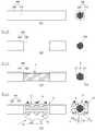
도 1은 종래의 현수교 주케이블 밴드장치의 개략적인 구성도.
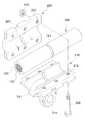
도 2는 본 발명의 실시예에 따른 현수교 주케이블 밴드장치의 분리사시도.
도 3은 도 2의 결합된 상태의 사시도.
도 4는 도 3의 단면도.
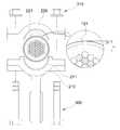
도 5는 본 발명에 있어서 오목홈과 돌기의 결합구조를 보이기 위한 참고단면도.
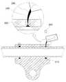
도 6은 본 발명의 사용상태 참고도.
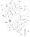
도 7은 본 발명의 다른 실시예에 따른 현수교 주케이블 밴드장치의 분리사시도.
도 8은 도 7의 결합된 상태의 사시도.
도 9는 도 8의 단면도.
도 10은 본 발명에 있어서 방수씰의 충진상태를 보이기 위한 참고단면도.BRIEF DESCRIPTION OF THE DRAWINGS FIG. 1 is a schematic view of a conventional suspension bridge main cable band device; FIG.
2 is an exploded perspective view of a suspension cable main cable band device according to an embodiment of the present invention;
Figure 3 is a perspective view of the combined state of Figure 2;
Fig. 4 is a sectional view of Fig. 3; Fig.
Fig. 5 is a cross-sectional view showing a coupling structure of a concave groove and a projection in the present invention. Fig.
6 is a use state reference diagram of the present invention.
FIG. 7 is an exploded perspective view of a suspension bridge cable band device according to another embodiment of the present invention; FIG.
Figure 8 is a perspective view of the combined state of Figure 7;
Fig. 9 is a sectional view of Fig. 8; Fig.
10 is a cross-sectional view for showing the filling state of the waterproof seal in the present invention.
이하, 첨부한 도면을 참고로 하여 본 발명의 실시예에 대하여 본 발명이 속하는 기술 분야에서 통상의 지식을 가진 자가 용이하게 실시할 수 있도록 상세히 설명한다. 그러나 본 발명은 여러 가지 상이한 형태로 구현될 수 있으며 여기에서 설명하는 실시예에 한정되지 않는다. 여기서 사용되는 전문용어는 단지 특정 실시예를 언급하기 위한 것이며, 본 발명을 한정하는 것을 의도하지 않는다. 또 여기서 사용되는 단수 형태들은 문구들이 이와 명백히 반대의 의미를 나타내지 않는 한 복수 형태들도 포함한다. 명세서에서 사용되는 "포함하는"의 의미는 특정 특성, 영역, 정수, 단계, 동작, 요소 및/또는 성분을 구체화하며, 다른 특정 특성, 영역, 정수, 단계, 동작, 요소, 성분 및/또는 군의 존재나 부가를 제외시키는 것은 아니다. 다르게 정의하지는 않았지만, 여기에 사용되는 기술용어 및 과학용어를 포함하는 모든 용어들은 본 발명이 속하는 기술분야에서 통상의 지식을 가진 자가 일반적으로 이해하는 의미와 동일한 의미를 가진다. 보통 사용되는 사전에 정의된 용어들은 관련기술문헌과 현재 개시된 내용에 부합하는 의미를 가지는 것으로 추가 해석되고, 정의되지 않는 한 이상적이거나 공식적인 의미로 해석되지 않는다.Hereinafter, exemplary embodiments of the present invention will be described in detail with reference to the accompanying drawings, which will be readily apparent to those skilled in the art to which the present invention pertains. The present invention may, however, be embodied in many different forms and should not be construed as limited to the embodiments set forth herein. The terminology used herein is for the purpose of describing particular embodiments only and is not intended to limit the invention. Also, the singular forms used herein include plural forms as long as the phrases do not expressly mean the opposite. Means that a particular feature, region, integer, step, operation, element and / or component is specified, and that other specific features, regions, integers, steps, operations, elements, components, and / And the like. Unless otherwise defined, all terms including technical and scientific terms used herein have the same meaning as commonly understood by one of ordinary skill in the art to which this invention belongs. Commonly used predefined terms are further construed to have meanings consistent with the relevant technical literature and the present disclosure and are not to be construed as ideal or official unless defined otherwise.
사시도를 참조하여 설명된 본 발명의 실시예는 본 발명의 이상적인 실시예를 구체적으로 나타낸다. 그 결과, 도해의 다양한 변형, 예를 들면 제조 방법 및/또는 사양의 변형이 예상된다. 따라서 실시예는 도시한 영역의 특정 형태에 국한되지 않으며, 예를 들면 제조에 의한 형태의 변형도 포함한다. 예를 들면, 편평하다고 도시되거나 설명된 영역은 일반적으로 거칠거나/거칠고 비선형인 특성을 가질 수 있다. 또한, 날카로운 각도를 가지는 것으로 도시된 부분은 라운드질 수 있다. 따라서 도면에 도시된 영역은 원래 대략적인 것에 불과하며, 이들의 형태는 영역의 정확한 형태를 도시하도록 의도된 것이 아니고, 본 발명의 범위를 좁히려고 의도된 것이 아니다.The embodiment of the present invention described with reference to the perspective view specifically illustrates an ideal embodiment of the present invention. As a result, various variations of the illustration, for example variations in the manufacturing method and / or specification, are expected. Thus, the embodiment is not limited to any particular form of the depicted area, but includes modifications of the form, for example, by manufacture. For example, the regions shown or described as being flat may have characteristics that are generally coarse / rough and nonlinear. Also, the portion shown as having a sharp angle may be rounded. Thus, the regions shown in the figures are merely approximate, and their shapes are not intended to depict the exact shape of the regions, nor are they intended to limit the scope of the present invention.
이하, 본 발명에 따른 현수교 주케이블 밴드장치에 대한 바람직한 실시예에 대해 첨부된 도면들을 참조로 하여 상세히 설명한다.DETAILED DESCRIPTION OF THE PREFERRED EMBODIMENTS Hereinafter, preferred embodiments of a suspension bridge cable band device according to the present invention will be described in detail with reference to the accompanying drawings.
우선, 도면들 중, 동일한 구성요소 또는 부품들은 가능한 동일한 참조부호로 나타내고 있음에 유의하여야 한다. 또한, 본 발명을 설명함에 있어, 관련된 공지기능 혹은 구성에 대한 구체적인 설명은 본 발명의 요지를 모호하지 않게 하기 위하여 생략하기로 한다.First, in the drawings, it is noted that the same components or parts are denoted by the same reference numerals as possible. In the following description of the present invention, a detailed description of known functions and configurations incorporated herein will be omitted so as to avoid obscuring the subject matter of the present invention.
본 발명의 실시예에 따른 현수교 주케이블 밴드장치는, 크게 교각(미도시)에 설치되는 주케이블(100)과, 상기 주케이블(100)에 매달리는 행어케이블(A)과, 상기 주케이블(100)과 행어케이블(A)을 연결하기 위한 밴드부(200)로 이루어진다.A suspension cable main band device according to an embodiment of the present invention mainly includes a
상기 주케이블(100)의 와이어다발(110)을 감싸고 있는 피복(120)에 일정간격으로 형성되는 오목홈(121)과, 상기 오목홈(121)에 삽입되기 위한 돌기(211)를 내측면에 구비하는 한쌍의 밴드부(200)로 이루어진다.A
이때 한쌍의 밴드부(200)는 하부 밴드(210)와 상부 밴드(220)으로 이루어지고, 이들의 결합은 볼트(300) 및 너트(310)로 이루어지는 체결구에 의해 이루어진다. 상기 체결구는 나사결합 가능한 구조여서 하부 밴드(210)와 상부 밴드(220) 사이의 이격 거리를 조절 가능하도록 한다.At this time, the pair of
또한 상기 하부 밴드(210)에는 행어케이블(A)과 연결되는 행어 케이블 연결부(214)를 포함할 수도 있다.The
상기 하부 밴드(210)와 상부 밴드(220)의 내주면은 반원형 또는 호형의 단면을 갖도록 형성됨이 바람직하고, 돌기(211)는 상기 내주면의 중앙에 형성된다.The inner circumferential surfaces of the
상기 주케이블(100)에 있어서 밴드부(200)가 결합되는 부분의 피복(120)은 강재와 결합력이 우수하고, 잘 수축되지 않으며, 구조적 강도가 우수한 에폭시를 사용함이 바람직하다.The
즉 에폭시재질의 피복(120)은 주케이블(100)의 전체에 행해지는 것보다 행어케이블(A)이 매달리는 부분, 즉 밴드부(200)가 결합되는 위치에만 일정 길이로 형성됨이 바람직하다. 이는 에폭시는 경화되면 신축성이 부족해지기 때문이다.That is, it is preferable that the
상기 에폭시(epoxy)는 내후성, 내부식성이 풍부한 플라스틱의 일종으로 코팅(coating) 재료, 나무, 금속, 유리, 도기, 고무 등의 접착제로도 사용되며 화이버 글래스(fiber glass)와 혼합하여 다양한 강화플래스틱 제품을 만들기도 하는 액체의 일종으로, 에폭시 외에도 기존 주케이블의 피복재료인 HDPE 피복에 오목홈(121)을 형성하여도 오목홈(121)과 돌기(211)의 걸림작용에 의해 마찰력과 함께 별도의 미끄럼 방지력을 제공할 수 있긴 하나 HDPE피복은 에폭시에 비해 다소 신축성을 갖는 재질이고 미끌림이 에폭시보다 큰 재질이어서 에폭시보다는 바람직하진 못하다. 물론 에폭시와 동일한 목적을 달성할 수 있는 피복물질이라면 어떤 것을 사용하여도 무방함은 당연하다.The epoxy is a kind of plastics with abundant weather resistance and corrosion resistance. It is also used as an adhesive for coating materials, wood, metal, glass, ceramics, rubber and the like. It is mixed with fiber glass, In addition to epoxy, in addition to the epoxy, the recessed
상기 피복(120)의 오목홈(121) 깊이와 밴드부(200)의 돌기(211)의 돌출높이는 동일하게 형성함이 바람직하다. 또한 피복(120)의 오목홈(121) 깊이(h)는 피복(120)의 두께(H)보다 작게 형성됨이 바람직하다. 만약 피복(120)의 오목홈(121) 깊이(h)가 피복(120)의 두께(H)와 같게 되면 와이어다발(110)의 표면이 노출되어 부식에 의한 내구성 약화가 필연적이기 때문이다.It is preferable that the depth of the
또한 본 발명은 밴드부(200)를 주케이블(100)의 피복(120)에 결합하는 과정 중에 피복(120)을 과도하게 조임으로써 발생될 수 있는 피복(120)의 균열 등에 의한 수분침투 등을 방지하기 위해 밴드부(200)의 내측면 돌기(211) 양측에는 방수씰 충진홈(213,223)을 형성함이 바람직하다.The present invention also prevents moisture penetration due to cracks or the like of the
또한 상기 밴드부(200)에는 상기 방수씰 충진홈(213,223)과 연통되는 방수씰 주입공(230)이 형성되고, 상기 방수씰 주입공(230)을 막기위한 마개(240)로 이루어진다.The
상기 방수씰 충진홈(213,223)에는 에폭시 등과 같과 같은 방수씰(250)이 충진되도록 함으로써 오목홈(121)을 통한 습기 유입을 방지할 수 있도록 한다.The waterproof
물론 상기 방수씰(250)은 방수기능이 가능하고 내구성이 좋은 재질이라면 에폭시 외 다른 어떤 소재라도 무방하다. Of course, the
이때 상기 방수씰 주입공(230)의 내측면은 나사산이 형성되어 상기 방수씰 주입공(230)을 막기위한 마개(240)가 나사결합 가능토록 구성됨이 바람직하다. 따라서 상기 마개(240)로는 볼트를 사용할 수도 있다.At this time, the inner surface of the waterproof
이처럼 본 발명은 피복(120)에 형성된 오목홈(121)에 밴드부(200)의 돌기(211)가 걸리도록 함으로써 마찰력은 물론 오목홈(121)과 돌기(211)의 걸림작용에 의해 주케이블(100)과 밴드부(200) 사이에 충분한 미끌림 방지력을 확보할 수 있는 구조인 것이다.As described above, according to the present invention, the
즉 본 발명의 미끄럼 방지력은 체결구의 체결 응력에 의한 미끄럼 방지력에 오목홈(121)과 돌기(211)의 걸림작용에 의한 미끄럼 방지력을 더한 값으로, 이는 기존 밴드장치의 체결구의 체결 응력에 의한 미끄럼 방지력에 비해 당연히 더 큰 값을 얻게 된다.That is, the anti-slip force of the present invention is a value obtained by adding the anti-slip force by the fastening stress of the fastener to the anti-slip force by the fastening action of the
따라서 본 발명은 주케이블에 대한 행어 케이블의 미끄러짐에 대한 충분한 저항을 확보하여 교량의 안정적인 지지가 가능하다.Therefore, the present invention ensures a sufficient resistance against slipping of the hanger cable to the main cable, thereby stably supporting the bridge.
상술 한 바와 같이 본 발명은 비록 한정된 실시예들에 의해 설명되었으나, 본 발명은 이것에 한정되지 않으며, 본 발명이 속하는 기술분야에서 통상의 지식을 가진 자에 의해 본 발명의 기술사상과 아래에 기재될 특허 청구범위의 균등범위 내에서 다양한 수정 및 변형이 가능하다 할 것이다.Although the present invention has been described in connection with certain exemplary embodiments, it is to be understood that the present invention is not limited thereto and that various changes and modifications will be apparent to those skilled in the art. Various modifications and variations are possible within the scope of the appended claims.
100: 주케이블110: 와이어다발
120: 파복121: 오목홈
200: 밴드부211: 돌기
213, 223 : 방수 씰(seal) 충진홈
214: 행어케이블 연결구
230: 방수씰 주입공240: 마개
250: 방수씰
300: 볼트310: 너트
A: 행어케이블100: main cable 110: wire bundle
120: Breaker 121: Concave groove
200: band portion 211: projection
213, 223: Waterproof seal Filling groove
214: Hanger cable connector
230: Waterproof seal injection hole 240: Plug
250: Waterproof seal
300: bolt 310: nut
A: Hangar cable
Claims (4)
Translated fromKorean상기 밴드부(200)에는 방수씰 충진홈(213,223)과 연통되는 방수씰 주입공(230)과, 상기 방수씰 주입공(230)을 막기위한 마개(240)를 구비함을 특징으로 하는 현수교 주케이블 밴드장치.
And a band portion for connecting the main cable and the hanger cable, wherein the main cable includes a main cable, a hanger cable hanging from the main cable, and a band portion for connecting the main cable and the hanger cable, And a pair of band portions provided on the inner surface of the main cable band device for insertion into the concave groove,
The band part 200 is provided with a waterproof seal injection hole 230 communicating with the waterproof seal filling grooves 213 and 223 and a stopper 240 for blocking the waterproof seal injection hole 230. Band device.
The suspension cable main cable band device according to claim 2, wherein the covering is an epoxy material.
Priority Applications (1)
| Application Number | Priority Date | Filing Date | Title |
|---|---|---|---|
| KR1020160032745AKR101676749B1 (en) | 2016-03-18 | 2016-03-18 | Band apparatus for main cable of suspension bridge |
Applications Claiming Priority (1)
| Application Number | Priority Date | Filing Date | Title |
|---|---|---|---|
| KR1020160032745AKR101676749B1 (en) | 2016-03-18 | 2016-03-18 | Band apparatus for main cable of suspension bridge |
Publications (1)
| Publication Number | Publication Date |
|---|---|
| KR101676749B1true KR101676749B1 (en) | 2016-11-17 |
Family
ID=57542193
Family Applications (1)
| Application Number | Title | Priority Date | Filing Date |
|---|---|---|---|
| KR1020160032745AExpired - Fee RelatedKR101676749B1 (en) | 2016-03-18 | 2016-03-18 | Band apparatus for main cable of suspension bridge |
Country Status (1)
| Country | Link |
|---|---|
| KR (1) | KR101676749B1 (en) |
Cited By (6)
| Publication number | Priority date | Publication date | Assignee | Title |
|---|---|---|---|---|
| CN107217595A (en)* | 2017-07-03 | 2017-09-29 | 德阳天元重工股份有限公司 | A kind of all welded type cord clip |
| CN109610317A (en)* | 2018-10-30 | 2019-04-12 | 武汉船用机械有限责任公司 | Waterproof cord clip |
| KR101945159B1 (en)* | 2018-10-08 | 2019-04-18 | 신상훈 | Double floor cable suspension pedestrian bridge |
| CN110528388A (en)* | 2019-09-19 | 2019-12-03 | 中交第二航务工程局有限公司 | A kind of installation point structure of overweight parallel steel wire suspension cable |
| CN114458733A (en)* | 2022-03-02 | 2022-05-10 | 华能青海发电有限公司新能源分公司 | T-shaped cable clamp for photovoltaic power station |
| CN115434242A (en)* | 2022-09-20 | 2022-12-06 | 东南大学 | A protective device and method suitable for bridge suspension viscoelastic vibration damping frame |
Citations (3)
| Publication number | Priority date | Publication date | Assignee | Title |
|---|---|---|---|---|
| JP2005207218A (en)* | 2004-07-26 | 2005-08-04 | Japan Highway Public Corp | Cable protection and securing method |
| CN103088755A (en)* | 2013-02-02 | 2013-05-08 | 四川天元机械工程股份有限公司 | Suspension bridge anti-skidding cable clamp |
| CN104264583A (en)* | 2013-07-04 | 2015-01-07 | 南通大学 | Spiral friction type anchoring tool with adjustable pre-tightening force used for fiber reinforced composite material rib inhaul cable |
- 2016
- 2016-03-18KRKR1020160032745Apatent/KR101676749B1/ennot_activeExpired - Fee Related
Patent Citations (3)
| Publication number | Priority date | Publication date | Assignee | Title |
|---|---|---|---|---|
| JP2005207218A (en)* | 2004-07-26 | 2005-08-04 | Japan Highway Public Corp | Cable protection and securing method |
| CN103088755A (en)* | 2013-02-02 | 2013-05-08 | 四川天元机械工程股份有限公司 | Suspension bridge anti-skidding cable clamp |
| CN104264583A (en)* | 2013-07-04 | 2015-01-07 | 南通大学 | Spiral friction type anchoring tool with adjustable pre-tightening force used for fiber reinforced composite material rib inhaul cable |
Cited By (6)
| Publication number | Priority date | Publication date | Assignee | Title |
|---|---|---|---|---|
| CN107217595A (en)* | 2017-07-03 | 2017-09-29 | 德阳天元重工股份有限公司 | A kind of all welded type cord clip |
| KR101945159B1 (en)* | 2018-10-08 | 2019-04-18 | 신상훈 | Double floor cable suspension pedestrian bridge |
| CN109610317A (en)* | 2018-10-30 | 2019-04-12 | 武汉船用机械有限责任公司 | Waterproof cord clip |
| CN110528388A (en)* | 2019-09-19 | 2019-12-03 | 中交第二航务工程局有限公司 | A kind of installation point structure of overweight parallel steel wire suspension cable |
| CN114458733A (en)* | 2022-03-02 | 2022-05-10 | 华能青海发电有限公司新能源分公司 | T-shaped cable clamp for photovoltaic power station |
| CN115434242A (en)* | 2022-09-20 | 2022-12-06 | 东南大学 | A protective device and method suitable for bridge suspension viscoelastic vibration damping frame |
Similar Documents
| Publication | Publication Date | Title |
|---|---|---|
| KR101676749B1 (en) | Band apparatus for main cable of suspension bridge | |
| JP5458094B2 (en) | Finishing elements, structures and methods for liquid-tight sealing of surfaces | |
| CA2651242C (en) | Ground anchor or rock anchor with an anchor tension member comprised of one or more individual elements with corrosion-protected anchor head design | |
| GB2157788A (en) | Anchoring devices | |
| US9441375B2 (en) | Steel bar sealing apparatus and method | |
| KR101713525B1 (en) | Chiropractors permanent anchor friction | |
| US4616458A (en) | Protective apparatus for tendons in tendon tensioning anchor assemblies | |
| KR101353512B1 (en) | Fixing unit for a outside panel of building | |
| KR101247565B1 (en) | Sealed type cap nut | |
| CN215561851U (en) | Bridge suspender and stay cable waterproof device | |
| KR200428458Y1 (en) | Anchor Bolt Protective Cap | |
| FI121692B (en) | Connection piece for coated overhead lines | |
| KR20180079685A (en) | Waterproof structure of upper steel anckorage for permanent anchor | |
| KR102089552B1 (en) | A bolt assembly | |
| CN112411376B (en) | Cable anti-slip device and installation method thereof | |
| JP2015010354A (en) | Water cutoff member for ground anchor | |
| JP5781413B2 (en) | Anchor bolt installation structure, its maintenance method and construction method | |
| KR101497228B1 (en) | Sealant preferred filling waterproofing method of prefabricated structure joint | |
| CN210529472U (en) | Anti-sliding key anchoring steel strand inhaul cable with fork ear cones | |
| KR20110024134A (en) | The protective device for railroad cable | |
| CN111560848A (en) | Sealing protection device and sealing method for connecting section of steel strand cable anchorage | |
| KR200400693Y1 (en) | Inner inserted staying tool for ground anchor | |
| KR101359792B1 (en) | Reclamation type washer member, and member fixing device and member fixing structure using the same | |
| KR200398518Y1 (en) | Structure for fixing of finger plate | |
| KR102278799B1 (en) | Method for constructing roof panels with fixtures |
Legal Events
| Date | Code | Title | Description |
|---|---|---|---|
| PA0109 | Patent application | St.27 status event code:A-0-1-A10-A12-nap-PA0109 | |
| PA0201 | Request for examination | St.27 status event code:A-1-2-D10-D11-exm-PA0201 | |
| PA0302 | Request for accelerated examination | St.27 status event code:A-1-2-D10-D17-exm-PA0302 St.27 status event code:A-1-2-D10-D16-exm-PA0302 | |
| D13-X000 | Search requested | St.27 status event code:A-1-2-D10-D13-srh-X000 | |
| D14-X000 | Search report completed | St.27 status event code:A-1-2-D10-D14-srh-X000 | |
| PE0902 | Notice of grounds for rejection | St.27 status event code:A-1-2-D10-D21-exm-PE0902 | |
| E13-X000 | Pre-grant limitation requested | St.27 status event code:A-2-3-E10-E13-lim-X000 | |
| P11-X000 | Amendment of application requested | St.27 status event code:A-2-2-P10-P11-nap-X000 | |
| P13-X000 | Application amended | St.27 status event code:A-2-2-P10-P13-nap-X000 | |
| E701 | Decision to grant or registration of patent right | ||
| PE0701 | Decision of registration | St.27 status event code:A-1-2-D10-D22-exm-PE0701 | |
| GRNT | Written decision to grant | ||
| PR0701 | Registration of establishment | St.27 status event code:A-2-4-F10-F11-exm-PR0701 | |
| PR1002 | Payment of registration fee | St.27 status event code:A-2-2-U10-U11-oth-PR1002 Fee payment year number:1 | |
| PG1601 | Publication of registration | St.27 status event code:A-4-4-Q10-Q13-nap-PG1601 | |
| PN2301 | Change of applicant | St.27 status event code:A-5-5-R10-R11-asn-PN2301 | |
| P14-X000 | Amendment of ip right document requested | St.27 status event code:A-5-5-P10-P14-nap-X000 | |
| PN2301 | Change of applicant | St.27 status event code:A-5-5-R10-R14-asn-PN2301 | |
| P16-X000 | Ip right document amended | St.27 status event code:A-5-5-P10-P16-nap-X000 | |
| Q16-X000 | A copy of ip right certificate issued | St.27 status event code:A-4-4-Q10-Q16-nap-X000 | |
| S14-X000 | Exclusive voluntary license recorded | St.27 status event code:A-4-4-S10-S14-lic-X000 | |
| FPAY | Annual fee payment | Payment date:20190916 Year of fee payment:4 | |
| PR1001 | Payment of annual fee | St.27 status event code:A-4-4-U10-U11-oth-PR1001 Fee payment year number:4 | |
| PR1001 | Payment of annual fee | St.27 status event code:A-4-4-U10-U11-oth-PR1001 Fee payment year number:5 | |
| PR1001 | Payment of annual fee | St.27 status event code:A-4-4-U10-U11-oth-PR1001 Fee payment year number:6 | |
| PN2301 | Change of applicant | St.27 status event code:A-5-5-R10-R11-asn-PN2301 | |
| PN2301 | Change of applicant | St.27 status event code:A-5-5-R10-R14-asn-PN2301 | |
| R18-X000 | Changes to party contact information recorded | St.27 status event code:A-5-5-R10-R18-oth-X000 | |
| PR1001 | Payment of annual fee | St.27 status event code:A-4-4-U10-U11-oth-PR1001 Fee payment year number:7 | |
| P14-X000 | Amendment of ip right document requested | St.27 status event code:A-5-5-P10-P14-nap-X000 | |
| P16-X000 | Ip right document amended | St.27 status event code:A-5-5-P10-P16-nap-X000 | |
| Q16-X000 | A copy of ip right certificate issued | St.27 status event code:A-4-4-Q10-Q16-nap-X000 | |
| PC1903 | Unpaid annual fee | St.27 status event code:A-4-4-U10-U13-oth-PC1903 Not in force date:20231111 Payment event data comment text:Termination Category : DEFAULT_OF_REGISTRATION_FEE | |
| PC1903 | Unpaid annual fee | St.27 status event code:N-4-6-H10-H13-oth-PC1903 Ip right cessation event data comment text:Termination Category : DEFAULT_OF_REGISTRATION_FEE Not in force date:20231111 |