KR101674958B1 - The apparatus and method for controlling inter-cell interference - Google Patents
The apparatus and method for controlling inter-cell interferenceDownload PDFInfo
- Publication number
- KR101674958B1 KR101674958B1KR1020100088509AKR20100088509AKR101674958B1KR 101674958 B1KR101674958 B1KR 101674958B1KR 1020100088509 AKR1020100088509 AKR 1020100088509AKR 20100088509 AKR20100088509 AKR 20100088509AKR 101674958 B1KR101674958 B1KR 101674958B1
- Authority
- KR
- South Korea
- Prior art keywords
- cell
- interference
- base station
- information
- terminal
- Prior art date
- Legal status (The legal status is an assumption and is not a legal conclusion. Google has not performed a legal analysis and makes no representation as to the accuracy of the status listed.)
- Active
Links
- 238000000034methodMethods0.000titleclaimsabstractdescription83
- 238000004891communicationMethods0.000claimsabstractdescription25
- 230000005540biological transmissionEffects0.000claimsdescription27
- 230000011664signalingEffects0.000claimsdescription6
- 230000030279gene silencingEffects0.000description55
- 238000005259measurementMethods0.000description48
- 238000010586diagramMethods0.000description26
- 229920006934PMIPolymers0.000description23
- 230000008569processEffects0.000description23
- 230000004044responseEffects0.000description13
- CIWBSHSKHKDKBQ-JLAZNSOCSA-NAscorbic acidChemical compoundOC[C@H](O)[C@H]1OC(=O)C(O)=C1OCIWBSHSKHKDKBQ-JLAZNSOCSA-N0.000description11
- 230000015654memoryEffects0.000description8
- 238000012545processingMethods0.000description8
- 239000006185dispersionSubstances0.000description7
- 238000010295mobile communicationMethods0.000description6
- 230000008054signal transmissionEffects0.000description5
- 230000002452interceptive effectEffects0.000description3
- 230000010267cellular communicationEffects0.000description2
- 230000000694effectsEffects0.000description2
- 238000005516engineering processMethods0.000description2
- 230000002708enhancing effectEffects0.000description2
- 230000007774longtermEffects0.000description2
- 241000760358EnodesSpecies0.000description1
- 101000741965Homo sapiens Inactive tyrosine-protein kinase PRAG1Proteins0.000description1
- 102100038659Inactive tyrosine-protein kinase PRAG1Human genes0.000description1
- 238000003491arrayMethods0.000description1
- 230000008901benefitEffects0.000description1
- 230000001413cellular effectEffects0.000description1
- 230000008859changeEffects0.000description1
- 230000000295complement effectEffects0.000description1
- 238000011161developmentMethods0.000description1
- 230000006870functionEffects0.000description1
- 238000012423maintenanceMethods0.000description1
- 239000011159matrix materialSubstances0.000description1
- 238000012986modificationMethods0.000description1
- 230000004048modificationEffects0.000description1
- 230000001151other effectEffects0.000description1
- 230000010363phase shiftEffects0.000description1
- 238000011160researchMethods0.000description1
- 238000013468resource allocationMethods0.000description1
Images


Classifications
- H—ELECTRICITY
- H04—ELECTRIC COMMUNICATION TECHNIQUE
- H04L—TRANSMISSION OF DIGITAL INFORMATION, e.g. TELEGRAPHIC COMMUNICATION
- H04L5/00—Arrangements affording multiple use of the transmission path
- H04L5/003—Arrangements for allocating sub-channels of the transmission path
- H04L5/0032—Distributed allocation, i.e. involving a plurality of allocating devices, each making partial allocation
- H—ELECTRICITY
- H04—ELECTRIC COMMUNICATION TECHNIQUE
- H04L—TRANSMISSION OF DIGITAL INFORMATION, e.g. TELEGRAPHIC COMMUNICATION
- H04L5/00—Arrangements affording multiple use of the transmission path
- H04L5/003—Arrangements for allocating sub-channels of the transmission path
- H04L5/0058—Allocation criteria
- H04L5/0073—Allocation arrangements that take into account other cell interferences
- H—ELECTRICITY
- H04—ELECTRIC COMMUNICATION TECHNIQUE
- H04B—TRANSMISSION
- H04B17/00—Monitoring; Testing
- H04B17/30—Monitoring; Testing of propagation channels
- H04B17/309—Measuring or estimating channel quality parameters
- H04B17/345—Interference values
- H—ELECTRICITY
- H04—ELECTRIC COMMUNICATION TECHNIQUE
- H04B—TRANSMISSION
- H04B7/00—Radio transmission systems, i.e. using radiation field
- H04B7/02—Diversity systems; Multi-antenna system, i.e. transmission or reception using multiple antennas
- H04B7/022—Site diversity; Macro-diversity
- H04B7/024—Co-operative use of antennas of several sites, e.g. in co-ordinated multipoint or co-operative multiple-input multiple-output [MIMO] systems
- H—ELECTRICITY
- H04—ELECTRIC COMMUNICATION TECHNIQUE
- H04J—MULTIPLEX COMMUNICATION
- H04J11/00—Orthogonal multiplex systems, e.g. using WALSH codes
- H04J11/0023—Interference mitigation or co-ordination
- H04J11/005—Interference mitigation or co-ordination of intercell interference
- H—ELECTRICITY
- H04—ELECTRIC COMMUNICATION TECHNIQUE
- H04L—TRANSMISSION OF DIGITAL INFORMATION, e.g. TELEGRAPHIC COMMUNICATION
- H04L5/00—Arrangements affording multiple use of the transmission path
- H04L5/003—Arrangements for allocating sub-channels of the transmission path
- H04L5/0058—Allocation criteria
- H—ELECTRICITY
- H04—ELECTRIC COMMUNICATION TECHNIQUE
- H04W—WIRELESS COMMUNICATION NETWORKS
- H04W16/00—Network planning, e.g. coverage or traffic planning tools; Network deployment, e.g. resource partitioning or cells structures
- H04W16/02—Resource partitioning among network components, e.g. reuse partitioning
- H04W16/04—Traffic adaptive resource partitioning
- H—ELECTRICITY
- H04—ELECTRIC COMMUNICATION TECHNIQUE
- H04W—WIRELESS COMMUNICATION NETWORKS
- H04W72/00—Local resource management
- H04W72/12—Wireless traffic scheduling
- H—ELECTRICITY
- H04—ELECTRIC COMMUNICATION TECHNIQUE
- H04W—WIRELESS COMMUNICATION NETWORKS
- H04W72/00—Local resource management
- H04W72/20—Control channels or signalling for resource management
- H04W72/21—Control channels or signalling for resource management in the uplink direction of a wireless link, i.e. towards the network
- H—ELECTRICITY
- H04—ELECTRIC COMMUNICATION TECHNIQUE
- H04W—WIRELESS COMMUNICATION NETWORKS
- H04W72/00—Local resource management
- H04W72/50—Allocation or scheduling criteria for wireless resources
- H04W72/54—Allocation or scheduling criteria for wireless resources based on quality criteria
- H04W72/541—Allocation or scheduling criteria for wireless resources based on quality criteria using the level of interference
Landscapes
- Engineering & Computer Science (AREA)
- Signal Processing (AREA)
- Computer Networks & Wireless Communication (AREA)
- Quality & Reliability (AREA)
- Physics & Mathematics (AREA)
- Electromagnetism (AREA)
- Mobile Radio Communication Systems (AREA)
Abstract
Translated fromKorean
Description
Translated fromKorean본 발명은 무선 통신 시스템에 관한 것으로, 보다 상세하게는 셀 간 간섭을 제어하기 위한 장치 및 방법에 관한 것이다.The present invention relates to a wireless communication system, and more particularly, to an apparatus and method for controlling inter-cell interference.
분산 안테나 시스템(DAS: Distributed Antenna System)은 단일 기지국(base station)과 유선 또는 전용회선으로 연결된 다수의 분산 안테나를 활용하는 시스템이다. 기지국은 서비스를 제공하는 셀 내부에 분산되어 위치한 복수 개의 안테나를 구비한다. 분산 안테나 시스템은 복수 개의 안테나들이 셀 내에서 소정 거리 이상 떨어져 분산되어 위치한다는 점에서 복수 개의 기지국 안테나들이 셀 중앙에 집중되어 있는 집중형 안테나 시스템(CAS: Centralized Antenna System)과 구별된다. 집중형 안테나 시스템은 일반적으로 WCDMA(Wideband Code Division Multiple Access), HSPA(High Speed Packet Access), LTE(Long Term Evolution)/LTE-A(Long Term Evolution-Advanced), 802.16과 같은 셀룰러 통신 시스템으로 셀 기반의 구조에서 하나의 기지국에 다중 안테나를 설치하여 개루프-MIMO(Open Loop-Multi Input Multi Output), 페루프-MIMO(Close Loop-Multi Input Multi Output), Multi-BS-MIMO(multi-base station-multi input multi output) 등과 같은 다양한 다중 안테나 기법을 사용하는 시스템이다.A Distributed Antenna System (DAS) is a system that utilizes a single base station and a number of distributed antennas connected by wire or dedicated lines. A base station includes a plurality of antennas dispersedly disposed in a cell providing a service. The distributed antenna system is distinguished from a centralized antenna system (CAS: Centralized Antenna System) in which a plurality of base station antennas are concentrated at the center of a cell in that a plurality of antennas are dispersedly located at a predetermined distance or more in a cell. A centralized antenna system is generally a cellular communication system such as Wideband Code Division Multiple Access (WCDMA), High Speed Packet Access (HSPA), Long Term Evolution (LTE) (MIMO), multi-BS-MIMO (multi-base-MIMO), and multi-base-MIMO station-multi input multi-output).
분산 안테나 시스템은 분산 안테나 각각의 유닛이 해당 안테나의 영역을 자체적으로 관할하는 것이 아닌 셀 중앙의 기지국에서 셀 내 위치한 모든 분산 안테나 영역을 관할한다는 점에서 펨토 셀(Femto cell)과 구별된다. 또한, 분산 안테나 유닛들이 유선 또는 전용회선으로 연결되어 있다는 점에서 기지국과 중계기(RN: Relay Node) 사이가 무선으로 연결된 다중 홉 방식의 릴레이 시스템(relay system) 또는 애드혹(ad-hoc) 네트워크와도 구별된다. 또한, 기지국의 명령에 따라 분산 안테나 각각이 안테나에 인접한 각각의 단말에 서로 다른 신호를 전송할 수 있다는 점에서 단순히 신호를 증폭해서 전송하는 리피터(repeater) 구조와도 구별된다.A distributed antenna system is distinguished from a femtocell in that each unit of the distributed antennas controls not only the area of the corresponding antenna but also all the distributed antenna areas located in the cell in the base station in the center of the cell. In addition, since the distributed antenna units are connected by a wired line or a dedicated line, a multi-hop relay system or an ad-hoc network wirelessly connected between a base station and a relay node (RN) Respectively. In addition, it is distinguished from a repeater structure in which each of the distributed antennas transmits a different signal to each terminal adjacent to the antenna in response to a command from the base station, and simply amplifies and transmits the signal.
이러한 분산 안테나 시스템은 분산된 안테나들이 동시에 서로 다른 데이터 스트림을 송수신하여 단일 또는 다중의 단말을 지원할 수 있다는 점에서 일종의 다중 입출력(multiple input multiple output, MIMO) 시스템으로 볼 수 있다. MIMO 시스템 관점에서, 분산 안테나 시스템은 셀 내에 다양한 위치에 분산된 안테나들로 집중형 안테나 시스템에 비해 각 안테나별로 전송 영역이 축소되어 송신 전력을 감소시키는 효과를 얻을 수 있다. 또한, 안테나와 단말 간의 전송 거리 단축을 통해 경로 손실을 감소시켜 고속 데이터 전송률을 가능하게 함으로써, 셀룰러 시스템의 전송 용량 및 전력 효율을 높일 수 있고, 셀 내의 사용자의 위치에 상관없이 집중형 안테나 시스템에 상대적으로 균일한 품질의 통신성능을 만족시킬 수 있다. 또한, 기지국과 다수의 분산 안테나들이 유선 또는 전용회선으로 연결되어 있어, 신호 손실이 적고 안테나 간의 상관도 및 간섭이 감소되어 높은 신호대 간섭 잡음비(SINR: Signal to Interference plus Noise Ratio)를 가질 수 있다.Such a distributed antenna system can be regarded as a kind of multiple input multiple output (MIMO) system in that distributed antennas can simultaneously transmit and receive different data streams to support single or multiple terminals. From the viewpoint of the MIMO system, the distributed antenna system can reduce the transmission power by reducing the transmission area for each antenna compared with the centralized antenna system by using antennas dispersed at various positions in the cell. In addition, by reducing the transmission distance between the antenna and the terminal, it is possible to increase the transmission capacity and power efficiency of the cellular system by reducing the path loss and enabling a high data rate. In addition, The communication performance of relatively uniform quality can be satisfied. Also, since a base station and a plurality of distributed antennas are connected by a wire or a dedicated line, a signal loss is small, correlation between antennas and interference are reduced, and a high signal-to-interference plus noise ratio (SINR) can be obtained.
이와 같이, 분산 안테나 시스템은 차세대 이동 통신 시스템에서 기지국 증설 비용과 백홀(backhaul)망의 유지 비용을 줄이는 동시에, 서비스 커버리지의 확대와 채널용량 및 SINR의 향상을 위해, 기존의 집중형 안테나 시스템과 병행하거나 또는 집중형 안테나 시스템을 대체하여 셀룰러 통신의 새로운 기반이 될 수 있다.In this way, the distributed antenna system can reduce the cost of expanding the base station and the maintenance cost of the backhaul network in the next generation mobile communication system, and to increase the service coverage, channel capacity and SINR, Or can replace the convergent antenna system to become a new basis for cellular communication.
그러나, 아직까지 분산 안테나 시스템이 적용되는 다중 셀 환경에서 셀 간 간섭을 제어하기 위한 장치 및 방법에 대해 전혀 연구된 바가 없다.However, there is no research on an apparatus and method for controlling inter-cell interference in a multi-cell environment in which a distributed antenna system is applied.
본 발명에서 이루고자 하는 기술적 과제는 셀 간 간섭을 제어하기 위한 단말 장치를 제공하는 데 있다.SUMMARY OF THE INVENTION The present invention provides a terminal apparatus for controlling inter-cell interference.
본 발명에서 이루고자 하는 다른 기술적 과제는 셀 간 간섭을 제어하기 위한 기지국 장치를 제공하는 데 있다.Another object of the present invention is to provide a base station apparatus for controlling inter-cell interference.
본 발명에서 이루고자 하는 또 다른 기술적 과제는 단말의 셀 간 간섭을 제어하는 방법을 제공하는 데 있다.It is another object of the present invention to provide a method for controlling inter-cell interference of a terminal.
본 발명에서 이루고자 하는 또 다른 기술적 과제는 기지국의 셀 간 간섭을 제어하는 방법을 제공하는 데 있다.It is another object of the present invention to provide a method of controlling inter-cell interference of a base station.
본 발명에서 이루고자 하는 기술적 과제들은 상기 기술적 과제로 제한되지 않으며, 언급하지 않은 또 다른 기술적 과제들은 아래의 기재로부터 본 발명이 속하는 기술분야에서 통상의 지식을 가진 자에게 명확하게 이해될 수 있을 것이다.The technical problems to be solved by the present invention are not limited to the technical problems and other technical problems which are not mentioned can be understood by those skilled in the art from the following description.
상기의 기술적 과제를 달성하기 위한, 본 발명에 따른 셀 간 간섭을 제어하기 위한 단말은, 각 셀에 복수의 안테나가 분산되어 배치된 무선 통신 시스템에서, 각 인접 셀 별로 분산되어 배치된 안테나 중 상기 단말에 간섭을 미치는 안테나인 유효 안테나의 개수 정보, 상기 유효 안테나의 인덱스 정보 및 상기 각 인접 셀의 참조신호 패턴 정보 중 하나 이상을 이용하여 상기 각 인접 셀의 간섭 레벨을 측정하는 간섭 레벨 측정 모듈; 상기 각 인접 셀의 간섭 레벨을 사전에 설정된 임계값과 비교하여 상기 각 인접 셀에 간섭제한을 요청할지 여부를 결정하는 간섭제한 요청 결정 모듈; 및 상기 간섭제한을 요청하기로 결정한 하나 이상의 인접 셀의 정보를 서빙 기지국으로 전송하는 송신기를 포함할 수 있다.According to an aspect of the present invention, there is provided a terminal for controlling inter-cell interference in a wireless communication system in which a plurality of antennas are dispersed in each cell, An interference level measurement module for measuring an interference level of each neighboring cell using at least one of the number of effective antennas, which is an antenna that interferes with the terminal, index information of the effective antenna, and reference signal pattern information of each neighboring cell; An interference restriction request determining module for determining whether to request interference restriction to each neighboring cell by comparing the interference level of each neighboring cell with a preset threshold value; And a transmitter for transmitting information of the at least one neighboring cell determined to request the interference restriction to the serving base station.
또한, 상기 단말은, 상기 서빙 기지국으로부터 상기 유효 안테나의 개수 정보, 상기 유효 안테나의 인덱스 정보 및 상기 각 인접 셀의 참조신호 패턴에 대한 정보를 수신하는 수신기를 더 포함할 수 있다.The terminal may further include a receiver for receiving information on the number of effective antennas, index information on the effective antennas, and information on a reference signal pattern of each neighboring cell from the serving base station.
또한, 상기 단말은, 상기 각 인접 셀 별로 분산되어 배치된 안테나 중에서 상기 단말에 간섭을 미치는 안테나인 유효 안테나의 개수와 상기 유효 안테나의 인덱스를 결정하는 유효 안테나 결정 모듈을 더 포함할 수 있다.The terminal may further include an effective antenna determination module that determines the number of effective antennas and an index of the effective antennas, which are antennas that interfere with the terminal, among the antennas scattered for each adjacent cell.
상기의 다른 기술적 과제를 달성하기 위한, 본 발명에 따른 셀 간 간섭을 제어하기 위한 기지국은, 각 셀에 복수의 안테나가 분산되어 배치된 무선 통신 시스템에서, 하나 이상의 단말 또는 상기 하나 이상의 단말의 각 서빙 기지국으로부터 간섭 제한을 요청하는 메시지를 수신하는 수신기; 및 상기 하나 이상의 단말에게 간섭을 미치는 안테나로 사전에 정의되어 있는 유효 안테나 또는 상기 유효 안테나의 빔 패턴 그룹 중 상기 하나 이상의 단말에게 간섭을 미치는 특정 빔 패턴 그룹에 대해 특정 시간 및/또는 주파수 영역에서 오프하거나 혹은 사용을 제한하도록 프로세서를 포함할 수 있다.According to another aspect of the present invention, there is provided a base station for controlling inter-cell interference in a wireless communication system in which a plurality of antennas are distributed in each cell, A receiver for receiving a message requesting interference restriction from a serving base station; And a control unit for controlling, in response to a specific beam pattern group that interferes with the at least one terminal among the effective antenna or the beam pattern group of the effective antenna that is predefined by the antenna that interferes with the at least one terminal, Or may limit the use of the processor.
상기의 또 다른 기술적 과제를 달성하기 위한, 본 발명에 따른 단말의 셀 간 간섭을 제어하는 방법은, 각 셀에 복수의 안테나가 분산되어 배치된 무선 통신 시스템에서, 각 인접 셀 별로 분산되어 배치된 안테나 중 상기 단말에 간섭을 미치는 안테나인 유효 안테나의 개수 정보, 상기 유효 안테나의 인덱스 정보 및 상기 각 인접 셀의 참조신호 패턴 정보 중 하나 이상을 이용하여 상기 각 인접 셀의 간섭 레벨을 측정하는 단계; 상기 각 인접 셀의 간섭 레벨을 사전에 설정된 임계값과 비교하여 상기 각 인접 셀에 간섭제한을 요청할지 여부를 결정하는 단계; 및 상기 간섭제한을 요청하기로 결정한 하나 이상의 인접 셀의 정보를 서빙 기지국으로 전송하는 단계를 포함할 수 있다.According to another aspect of the present invention, there is provided a method of controlling inter-cell interference of a terminal in a wireless communication system in which a plurality of antennas are distributed and arranged in each cell, Measuring an interference level of each neighboring cell using at least one of information on the number of effective antennas, which is an antenna that interferes with the terminal among the antennas, index information of the effective antennas, and reference signal pattern information of each neighboring cell; Comparing the interference level of each neighboring cell with a preset threshold value to determine whether to request interference restriction to each neighboring cell; And transmitting the information of the at least one neighboring cell determined to request the interference restriction to the serving base station.
또한, 상기 방법은, 상기 서빙 기지국으로부터 상기 유효 안테나의 개수 정보, 상기 유효 안테나의 인덱스 정보 및 상기 각 인접 셀의 참조신호 패턴에 대한 정보를 수신하는 단계를 더 포함할 수 있다.The method may further include receiving information on the number of valid antennas, index information on the effective antennas, and information on a reference signal pattern of each neighboring cell from the serving base station.
또한, 상기 방법은, 상기 각 인접 셀 별로 분산되어 배치된 안테나 중에서 상기 단말에 간섭을 미치는 안테나인 유효 안테나의 개수와 상기 유효 안테나의 인덱스를 결정하는 단계를 더 포함할 수 있다.The method may further comprise determining a number of effective antennas and an index of the effective antennas, which are antennas that interfere with each other among the antennas scattered and arranged for each adjacent cell.
상기의 또 다른 기술적 과제를 달성하기 위한, 본 발명에 따른 기지국이 셀 간 간섭을 제어하기 위한 방법은, 각 셀에 복수의 안테나가 분산되어 배치된 무선 통신 시스템에서, 하나 이상의 단말 또는 상기 하나 이상의 단말의 각 서빙 기지국으로부터 간섭 제한을 요청하는 메시지를 수신하는 단계; 및 상기 하나 이상의 단말에게 간섭을 미치는 안테나로 사전에 정의되어 있는 유효 안테나 또는 상기 유효 안테나의 빔 패턴 그룹 중 상기 하나 이상의 단말에게 간섭을 미치는 특정 빔 패턴 그룹에 대해 특정 시간 및/또는 주파수 영역에서 오프하거나 혹은 사용을 제한하도록 제어하는 단계를 포함할 수 있다.According to another aspect of the present invention, there is provided a method for controlling inter-cell interference by a base station in a wireless communication system in which a plurality of antennas are distributed in each cell, The method comprising: receiving a message requesting interference restriction from each serving base station; And a control unit for controlling, in response to a specific beam pattern group that interferes with the at least one terminal among the effective antenna or the beam pattern group of the effective antenna that is predefined by the antenna that interferes with the at least one terminal, Or to limit the use of the device.
본 발명에 따른 셀 간 간섭을 제어하는 장치 및 방법에 의해, 셀 경계에 위치한 단말 등에 간섭을 적게 미치게 함으로써 통신 성능과 쓰루풋을 현저히 향상시키는 장점이 있다.The apparatus and method for controlling inter-cell interference according to the present invention have an advantage of remarkably improving communication performance and throughput by making interference to a terminal located at a cell boundary or the like less.
특히, 각 셀 별로 안테나가 분산되어 위치한 시스템에서 본 발명에 의하면 통신 성능을 현저히 향상시킬 수 있다.Particularly, according to the present invention, in a system in which antennas are dispersed for each cell, communication performance can be remarkably improved.
본 발명에서 얻은 수 있는 효과는 이상에서 언급한 효과들로 제한되지 않으며, 언급하지 않은 또 다른 효과들은 아래의 기재로부터 본 발명이 속하는 기술분야에서 통상의 지식을 가진 자에게 명확하게 이해될 수 있을 것이다.The effects obtained by the present invention are not limited to the above-mentioned effects, and other effects not mentioned can be clearly understood by those skilled in the art from the following description will be.
본 발명에 관한 이해를 돕기 위해 상세한 설명의 일부로 포함되는, 첨부 도면은 본 발명에 대한 실시예를 제공하고, 상세한 설명과 함께 본 발명의 기술적 사상을 설명한다.
도 1은 본 발명에 따른 무선 통신 시스템에서의 기지국(105) 및 단말 장치의 구성을 도시한 블록도,
도 2는 이동통신 시스템의 일례인 3GPP(3rd Generation Partnership Project) LTE(Long Term Evolution) 시스템 등에 이용되는 물리 채널들 및 이들을 이용한 일반적인 신호 전송 방법을 설명하기 위한 도면,
도 3은 기지국(105)이 하향링크 신호 전송을 위해 하향링크 물리 채널을 나타내는 기저대역 신호가 처리되는 과정을 설명하기 위한 예시적인 도면,
도 4는 분산 안테나 시스템(DAS)의 개념을 설명하기 위한 예시적인 도면,
도 5는 다중 셀 기반 환경의 분산 안테나 시스템에서 셀 간 간섭을 제어하기 위한 단말(500)의 구성을 개략적으로 도시한 블록도이고, 도 6은 단말(500)의 프로세서(540)의 구성을 도시한 블록도,
도 6은 단말(500)의 프로세서(540)의 상세한 구성을 도시한 블록도,
도 7은 다중 셀 기반 분산 안테나 시스템에서 셀 간 간섭을 제어하기 위한 방법을 설명하기 위한 예시적인 도면,
도 8은 본 발명에 따른 기지국 장치의 구성을 나타낸 블록도,
도 9는 본 발명에 따른 인접 셀의 기지국(900) 장치의 구성을 도시한 블록도,
도 10 및 도 11은 각각 기지국 간의 정보 교환을 하는 과정의 예를 나타낸 도면,
도 12는 인접 기지국인 기지국 2가 간섭제한 요청에 대해 스케줄링을 수행하여 기지국 간에 스케줄링 정보를 공유하는 과정의 예를 나타낸 도면,
도 13은 인접 기지국인 기지국 2가 간섭제한 요청에 대해 스케줄링을 수행하여 기지국 간에 스케줄링 정보를 공유하는 과정의 다른 예를 나타낸 도면, 그리고,
도 14는 인접 기지국인 기지국 2가 간섭제한 요청에 대해 스케줄링을 수행하여 기지국 간에 스케줄링 정보를 공유하는 과정의 다른 예를 나타낸 도면이다.BRIEF DESCRIPTION OF THE DRAWINGS The accompanying drawings, which are included to provide a further understanding of the invention and are incorporated in and constitute a part of the specification, illustrate embodiments of the invention and, together with the description, serve to explain the principles of the invention.
1 is a block diagram showing the configuration of a
2 is a diagram for explaining physical channels used in a 3rd Generation Partnership Project (3GPP) LTE (Long Term Evolution) system, which is an example of a mobile communication system, and a general signal transmission method using them;
3 is an exemplary diagram for explaining a process in which the
4 is an exemplary diagram for illustrating the concept of a distributed antenna system (DAS)
FIG. 5 is a block diagram schematically illustrating a configuration of a
6 is a block diagram showing a detailed configuration of the
7 is an exemplary diagram illustrating a method for controlling inter-cell interference in a multi-cell based distributed antenna system,
8 is a block diagram showing a configuration of a base station apparatus according to the present invention.
9 is a block diagram showing a configuration of a
10 and 11 are views illustrating an example of a process of exchanging information between base stations,
12 is a diagram illustrating an example of a process in which a
13 is a diagram illustrating another example of a process in which a
FIG. 14 is a diagram illustrating another example of a process in which a
이하, 본 발명에 따른 바람직한 실시 형태를 첨부된 도면을 참조하여 상세하게 설명한다. 첨부된 도면과 함께 이하에 개시될 상세한 설명은 본 발명의 예시적인 실시형태를 설명하고자 하는 것이며, 본 발명이 실시될 수 있는 유일한 실시형태를 나타내고자 하는 것이 아니다. 이하의 상세한 설명은 본 발명의 완전한 이해를 제공하기 위해서 구체적 세부사항을 포함한다. 그러나, 당업자는 본 발명이 이러한 구체적 세부사항 없이도 실시될 수 있음을 안다. 예를 들어, 이하의 상세한 설명은 이동통신 시스템이 3GPP LTE 시스템인 경우를 가정하여 구체적으로 설명하나, 3GPP LTE의 특유한 사항을 제외하고는 다른 임의의 이동통신 시스템에도 적용 가능하다.Hereinafter, preferred embodiments according to the present invention will be described in detail with reference to the accompanying drawings. DETAILED DESCRIPTION OF THE PREFERRED EMBODIMENTS The following detailed description, together with the accompanying drawings, is intended to illustrate exemplary embodiments of the invention and is not intended to represent the only embodiments in which the invention may be practiced. The following detailed description includes specific details in order to provide a thorough understanding of the present invention. However, those skilled in the art will appreciate that the present invention may be practiced without these specific details. For example, the following detailed description is based on the assumption that the mobile communication system is a 3GPP LTE system, but it is applicable to any other mobile communication system except for the specific aspects of 3GPP LTE.
몇몇 경우, 본 발명의 개념이 모호해지는 것을 피하기 위하여 공지의 구조 및 장치는 생략되거나, 각 구조 및 장치의 핵심기능을 중심으로 한 블록도 형식으로 도시될 수 있다. 또한, 본 명세서 전체에서 동일한 구성요소에 대해서는 동일한 도면 부호를 사용하여 설명한다. 명세서에서 제시하는 '예시적인' 실시 형태는 뜻은 다른 실시 형태들보다 꼭 더 바람직한 실시 형태를 의미하는 것은 아니다.In some instances, well-known structures and devices may be omitted or may be shown in block diagram form, centering on the core functionality of each structure and device, to avoid obscuring the concepts of the present invention. In the following description, the same components are denoted by the same reference numerals throughout the specification. The " exemplary " embodiments set forth in the specification do not imply a more preferred embodiment than the other embodiments.
아울러, 이하의 설명에 있어서 단말은 UE(User Equipment), MS(Mobile Station), AMS(Advanced Mobile Station) 등 이동 또는 고정형의 사용자단 기기를 통칭하는 것을 가정한다. 또한, 기지국은 Node B, eNode B, Base Station, AP(Access Point) 등 단말과 통신하는 네트워크 단의 임의의 노드를 통칭하는 것을 가정한다.In the following description, it is assumed that the UE collectively refers to a mobile stationary or stationary user equipment such as a UE (User Equipment), an MS (Mobile Station), and an AMS (Advanced Mobile Station). It is also assumed that the base station collectively refers to any node at a network end that communicates with a terminal such as a Node B, an eNode B, a base station, and an access point (AP).
이동 통신 시스템에서 단말(User Equipment)은 기지국으로부터 하향링크(Downlink)를 통해 정보를 수신할 수 있으며, 단말은 또한 상향링크(Uplink)를 통해 정보를 전송할 수 있다. 단말이 전송 또는 수신하는 정보로는 데이터 및 다양한 제어 정보가 있으며, 단말이 전송 또는 수신하는 정보의 종류 용도에 따라 다양한 물리 채널이 존재한다. 본 발명에서 사용하는 기지국이라는 용어는 지역적인 의미로 사용되는 경우 셀 혹은 섹터로 사용될 수도 있다.In a mobile communication system, a user equipment can receive information through a downlink from a base station, and the terminal can also transmit information through an uplink. The information transmitted or received by the terminal includes data and various control information, and various physical channels exist depending on the type of information transmitted or received by the terminal. The term " base station " used in the present invention may be used as a cell or a sector when used in a local sense.
도 1은 본 발명에 따른 무선 통신 시스템에서의 기지국(105) 및 단말(110) 의 구성을 도시한 블록도이다.1 is a block diagram showing the configuration of a
무선 통신 시스템(100)을 간략화하여 나타내기 위해 하나의 기지국(105)과 하나의 단말(110)을 도시하였지만, 하나 이상의 기지국 및/또는 하나 이상의 단말기를 포함할 수 있다.Although one
도 1을 참조하면, 기지국(105)은 송신(Tx) 데이터 프로세서(115), 심볼 변조기(120), 송신기(125), 송수신 안테나(130), 프로세서(180), 메모리(185), 수신기(190), 심볼 복조기(195), 수신 데이터 프로세서(197)를 포함할 수 있다. 그리고, 단말(110)은 송신(Tx) 데이터 프로세서(165), 심볼 변조기(170), 송신기(175), 송수신 안테나(135), 프로세서(155), 메모리(160), 수신기(140), 심볼 복조기(155), 수신 데이터 프로세서(150)를 포함할 수 있다. 안테나(130, 135)가 각각 기지국(105) 및 단말(110)에서 하나로 도시되어 있지만, 기지국(105) 및 단말(110)은 복수 개의 안테나를 구비한 다중 안테나이다. 따라서, 본 발명에 따른 기지국(105) 및 단말(110)은 MIMO(Multiple Input Multiple Output) 시스템을 지원한다. 본 발명에 따른 기지국(105) 및 단말(110)은 SU-MIMO(Single User-MIMO) MU-MIMO(Multi User-MIMO) 방식 모두를 지원한다.1, a
하향링크 상에서, 송신 데이터 프로세서(115)는 트래픽 데이터를 수신하고, 수신한 트래픽 데이터를 포맷하여, 코딩하고, 코딩된 트래픽 데이터를 인터리빙하고 변조하여(또는 심볼 매핑하여), 변조 심볼들("데이터 심볼들") 을 제공한다. 심볼 변조기(120)는 이 데이터 심볼들과 파일럿 심볼들을 수신 및 처리하여, 심볼들의 스트림을 제공한다.On the downlink, the transmit
심볼 변조기(120)는, 데이터 및 파일럿 심볼들을 다중화하여 이를 송신기 (125)로 전송한다. 이때, 각각의 송신 심볼은 데이터 심볼, 파일럿 심볼, 또는 제로의 신호 값일 수도 있다. 각각의 심볼 주기에서, 파일럿 심볼들이 연속적으로 송신될 수도 있다. 파일럿 심볼들은 주파수 분할 다중화(FDM), 직교 주파수 분할 다중화(OFDM), 시분할 다중화(TDM), 또는 코드 분할 다중화(CDM) 심볼일 수 있다.The symbol modulator 120 multiplexes the data and pilot symbols and transmits it to the
송신기(125)는 심볼들의 스트림을 수신하여 이를 하나 이상의 아날로그 신호들로 변환하고, 또한, 이 아날로그 신호들을 추가적으로 조절하여(예를 들어, 증폭, 필터링, 및 주파수 업 컨버팅(upconverting) 하여, 무선 채널을 통한 송신에 적합한 하향링크 신호를 발생시킨다. 이어서, 하향링크 신호는 안테나(130)를 통해 단말로 전송된다.
단말(110)에서, 안테나(135)는 기지국으로부터의 하향링크 신호를 수신하여 수신된 신호를 수신기(140)로 제공한다. 수신기(140)는 수신된 신호를 조정 하여(예를 들어, 필터링, 증폭, 및 주파수 다운컨버팅(downconverting))하고, 조정된 신호를 디지털화하여 샘플들을 획득한다. 심볼 복조기(145) 는 수신된 파일럿 심볼들을 복조하여 채널 추정을 위해 이를 프로세서(155)로 제공한다.At the terminal 110, the
또한, 심볼 복조기(145)는 프로세서(155)로부터 하향링크에 대한 주파수 응답 추정치를 수신하고, 수신된 데이터 심볼들에 대해 데이터 복조를 수행하여, (송신된 데이터 심볼들의 추정치들인) 데이터 심볼 추정치를 획득하고, 데이터 심볼 추정치들을 수신(Rx) 데이터 프로세서(150)로 제공한다. 수신 데이터 프로세서 (150)는 데이터 심볼 추정치들을 복조(즉, 심볼 디-매핑(demapping))하고, 디인터리빙(deinterleaving)하고, 디코딩하여, 전송된 트래픽 데이터를 복구한다.
심볼 복조기(145) 및 수신 데이터 프로세서(150)에 의한 처리는 각각 기지국(105)에서의 심볼 변조기(120) 및 송신 데이터 프로세서(115)에 의한 처리에 대해 상보적이다. The processing by
단말(110)은 상향링크 상에서, 송신 데이터 프로세서(165)는 트래픽 데이터를 처리하여, 데이터 심볼들을 제공한다. 심볼 변조기(170)는 데이터 심볼들을 수신하여 파일럿 심볼들과 함께 다중화하여, 변조를 수행하여, 심볼들의 스트림을 송신기(175)로 제공한다. 송신기(175)는 심볼들의 스트림을 수신 및 처리하여, 상향링크 신호를 발생시키고, 이러한 상향링크 신호는 안테나(135)를 통해 기지국(105)으로 전송된다.On the uplink, the terminal 110 processes the traffic data and provides data symbols. A
기지국(105)에서, 단말(110)로부터 상향링크 신호가 안테나(130)를 통해 를 수신되고, 수신기(190)는 수신한 상향링크 신호를 처리되어 샘플들을 획득한다. 이어서, 심볼 복조기(195)는 이 샘플들을 처리하여, 상향링크에 대해 수신된 파일럿 심볼들 및 데이터 심볼 추정치를 제공한다. 수신 데이터 프로세서(197)는 데이터 심볼 추정치를 처리하여, 단말기(110)로부터 전송된 트래픽 데이터를 복구한다.In the
단말(110) 및 기지국(105) 각각의 프로세서(155, 180)는 각각 단말(110) 및 기지국(105)에서의 동작을 지시(예를 들어, 제어, 조정, 관리 등)한다. 각각의 프로세서들(155, 180)은 프로그램 코드들 및 데이터를 저장하는 메모리 유닛(160, 185)들과 연결될 수 있다. 메모리(160, 185)는 프로세서(180)에 연결되어 오퍼레이팅 시스템, 어플리케이션, 및 일반 파일(general files)들을 저장한다.The
프로세서(155, 180)는 컨트롤러(controller), 마이크로 컨트롤러(microcontroller), 마이크로 프로세서(microprocessor), 마이크로 컴퓨터(microcomputer) 등으로도 호칭될 수 있다.The
한편, 프로세서(155, 180)는 하드웨어(hardware) 또는 펌웨어(firmware), 소프트웨어, 또는 이들의 결합에 의해 구현될 수 있다. 하드웨어를 이용하여 본 발명의 실시예들에 따른 셀 간 간섭을 제어하기 위한 방법을 구현하는 경우에는, 본 발명을 수행하도록 구성된 ASICs(application specific integrated circuits) 또는 DSPs(digital signal processors), DSPDs(digital signal processing devices), PLDs(programmable logic devices), FPGAs(field programmable gate arrays) 등이 프로세서(155, 180)에 구비될 수 있다.Meanwhile, the
한편, 펌웨어나 소프트웨어를 이용하여 본 발명의 실시예들에 따른 셀 간 간섭을 제어하기 위한 방법을 구현하는 경우에는 본 발명의 기능 또는 동작들을 수행하는 모듈, 절차 또는 함수 등을 포함하도록 펌웨어나 소프트웨어가 구성될 수 있으며, 본 발명을 수행할 수 있도록 구성된 펌웨어 또는 소프트웨어는 프로세서(155, 180) 내에 구비되거나 메모리(160, 185)에 저장되어 프로세서(155, 180)에 의해 구동될 수 있다.Meanwhile, when a method for controlling inter-cell interference according to embodiments of the present invention is implemented using firmware or software, a method for controlling inter-cell interference by using firmware or software, such as a module, a procedure or a function, And firmware or software configured to perform the present invention may be stored in the
단말(110)과 기지국(105)이 무선 통신 시스템(네트워크) 사이의 무선 인터페이스 프로토콜의 레이어들은, 통신 시스템에서 잘 알려진 OSI(open system interconnection) 모델의 하위 3개 레이어를 기초로 제 1 레이어(L1), 제 2 레이어(L2), 및 제 3 레이어(L3)로 분류될 수 있다. 물리 레이어는 상기 제1 레이어에 속하며, 물리 채널을 통해 정보 전송 서비스를 제공한다. RRC(Radio Resource Control) 레이어는 상기 제 3 레이어에 속하며 UE와 네트워크 사이의 제어 무선 자원들을 제공한다. 단말(110), 기지국(105)은 무선 통신 네트워크와 RRC 레이어를 통해 RRC 메시지들을 교환한다.The layers of the air interface protocol between the terminal 110 and the
3GPP LTE 시스템에 있어서, 상향링크 신호와 하향링크 신호를 전송하기 위한 신호 처리 과정을 설명하면 다음과 같다.In the 3GPP LTE system, a signal processing process for transmitting an uplink signal and a downlink signal will be described.
도 2는 상향링크 신호 전송을 위해 상향링크 물리 채널을 나타내는 기저대역 신호가 처리되는 과정을 설명하기 위한 예시적인 도면이다.2 is an exemplary diagram illustrating a process of processing a baseband signal representing an uplink physical channel for uplink signal transmission.
단말(110)에서, 스크램블링 모듈(210)은 상향링크 신호를 전송하기 위해 단말(110) 특정 스크램블링 신호를 이용하여 전송 신호를 스크램블링할 수 있다. 이와 같이 스크램블링된 신호는 변조 맵퍼(220)에 제공되어 전송 신호의 종류 및/또는 채널 상태에 따라 BPSK(Binary Phase Shift Keying), QPSK(Quadrature Phase Shift Keying) 또는 16 QAM(Quadrature Amplitude Modulation) 방식으로 복소 심볼로 변조된다. 그 후, 변조된 복소 심볼은 변환 프리코더(230)에 의해 처리된 후, 자원 요소 맵퍼(240)에 제공되며, 자원 요소 맵퍼(240)는 복소 심볼을 실제 전송에 이용될 시간-주파수 자원 요소에 맵핑할 수 있다. 이와 같이 처리된 신호는 SC-FDMA 신호 생성기(250)를 거쳐 RF(Radio Frequency) 신호로 변환되어 안테나(135)를 통해 기지국으로 전송될 수 있다.In the terminal 110, the
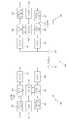
도 3은 기지국(105)이 하향링크 신호 전송을 위해 하향링크 물리 채널을 나타내는 기저대역 신호가 처리되는 과정을 설명하기 위한 예시적인 도면이다.3 is an exemplary diagram illustrating a process in which the
3GPP LTE 시스템에서 기지국(105)은 하향링크로 하나 이상의 코드워드(codeword)를 전송할 수 있다. 따라서 하나 이상의 코드워드는 각각 도 2의 상향링크에서와 마찬가지로 스크램블링 모듈(310) 및 변조 맵퍼(320)를 통해 복소 심볼로서 처리될 수 있다, 그 후, 복소 심볼은 레이어 맵퍼(330)에 의해 복수의 레이어(Layer)에 맵핑되며, 각 레이어는 프리코딩 모듈(340)에 의해 채널 상태에 따라 선택된 소정 프리코딩 행렬과 곱해져 자원 요소 맵퍼(350)로 제공된다. 자원 요소 맵퍼(350)는 프리코딩된 신호를 자원 요소에 매핑하여 OFDM 신호 생성기(360)로 제공하며, OFDM 신호 생성기(360)는 자원 요소 맵퍼(350)으로부터 수신한 신호를 처리하여 OFDM 신호를 생성하고, 이는 RF 신호로 변환되어 각 안테나(130)를 통해 단말(110)로 전송될 수 있다.In the 3GPP LTE system, the
이동통신 시스템의 표준의 관점에서, 현재와 미래의 통신규격에서 요구하는 높은 데이터 용량을 확보하기 위해서는 분산 안테나 시스템에서도 MIMO 전송을 지원할 필요가 있다. 즉, 필요에 따라 동일 주파수 영역에서 각 단말에게 랭크(r랭크 2 이상의 전송도 해주어야 하고, 여러 단말을 동시에 지원하는 MU-MIMO 전송도 지원하여야 한다. 이는 하향링크뿐만 아니라 상향링크에서도 고려되어야 한다. 이러한 SU-MIMO 및 MU-MIMO 통신은 양대 표준화 단체인 IEEE 802와 3GPP LTE에서 필수적으로 고려하고 있고, 실제로 IEEE 802.16, 3GPP LTE Release 8,9 등의 표준에서 다루고 있다. 그러나, 현재의 통신 규격들은 집중 안테나 시스템만을 고려하여 설계되어 MIMO기술과 같은 진보된 기술이 적용된 분산 안테나 시스템으로의 적용이 어려운 현실이다. 따라서, 향후 통신 시스템의 발전을 위해 분산 안테나 시스템을 지원하는 통신 규격이 필요하다.From the viewpoint of the standards of mobile communication systems, it is necessary to support MIMO transmission also in a distributed antenna system in order to secure high data capacity required in current and future communication standards. In other words, it is necessary to transmit ranks (
도 4는 분산 안테나 시스템(DAS)의 개념을 설명하기 위한 예시적인 도면이다.4 is an exemplary diagram for explaining the concept of a distributed antenna system (DAS).
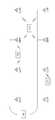
도 4를 참조하면, 분산 안테나 시스템은 각 셀에서 안테나들의 수와 위치에 따라 다양하게 구현될 수 있다. 분산 안테나 시스템의 각 셀에서 각 안테나는 소정 거리 이상 떨어져 흩어져서 분포할 수도 있고, 각 장소에 여러 개의 안테나가 그룹으로 뭉쳐서 존재할 수도 있다. 분산 안테나 시스템에서 안테나가 어떤 형태로 분포하던 안테나들의 커버리지가 오버랩(overlap)되어야만 랭크 2 이상의 전송이 가능하다. 이 점이 현재 구현된 분산 안테나 시스템과 앞으로 구현되어야 할 분산 안테나 시스템의 다른 점이라 할 수 있겠다. 총 8개의 안테나로 이루어진 분산 안테나 시스템에서 3개의 단말이 존재하고, 각 안테나의 커버리지는 인접 안테나 근처까지 미친다고 가정한다. 이 경우, 단말 1은 안테나 1, 2, 5, 6번의 신호는 수신할 수 있으나, 안테나 3, 4, 7, 8번의 신호는 경로 손실로 인해 무시할 만큼 작다. 마찬가지로, 단말 2의 입장에서는 안테나 6, 7번의 신호를 제외하고는 무시할 수 있을 만큼 약하고, 단말 3은 안테나 3번의 신호만 주요하게(dominantly) 수신할 수 있다.Referring to FIG. 4, the distributed antenna system can be variously implemented according to the number and location of antennas in each cell. In each cell of the distributed antenna system, the respective antennas may be scattered and distributed by a predetermined distance or more, and a plurality of antennas may be grouped together at each location. In the distributed antenna system, the coverage of the antennas distributed in any form is overlapped, and transmission is possible over
도 4에서 예시한 바와 같이, 분산 안테나 시스템에서는 셀 내에서 위치가 멀리 떨어진 단말들에 대한 MU-MIMO 방식 통신을 하는데 큰 문제가 없다. 예를 들어, 분산 안테나 시스템에서의 안테나 1, 2, 5, 6번은 단말 1과, 안테나 3번은 단말 3, 안테나 7번은 단말 2와 동시에 통신할 수 있다. 여기서, 분산 안테나 시스템은 안테나 4번과 8번은 단말 2나 단말 3을 위해 송신을 해 줄 수도 있고, 그냥 꺼진(off) 상태로 운영할 수도 있다.As illustrated in FIG. 4, in the distributed antenna system, there is no significant problem in performing MU-MIMO communication for terminals located far away in a cell. For example, in the distributed antenna system,
분산 안테나 시스템은 SU-MIMO, MU-MIMO 방식 통신시 각 단말 별로 데이터 스트림(layer)의 수가 다양하게 존재할 수 있고, 각 단말에 할당되는 안테나 혹은 안테나 그룹이 존재할 수 있다는 특징이 있다. 즉, 분산 안테나 시스템은 각 단말에 대해 특정 안테나 혹은 안테나 그룹이 지원 가능하고, 해당 안테나(혹은 안테나 그룹)의 수가 수시로 바뀔 수 있다.The distributed antenna system is characterized in that the number of data streams may vary depending on each terminal in the SU-MIMO and MU-MIMO communication, and an antenna or an antenna group allocated to each terminal may exist. That is, in the distributed antenna system, a specific antenna or an antenna group can be supported for each terminal, and the number of the corresponding antenna (or antenna group) can be changed from time to time.
기존의 집중형 안테나 시스템에서 협력적 MIMO 방식의 전송은 다중 셀 환경에서 셀 간 간섭(Inter-Cell Interference)을 줄이기 위해 제안된 것이다. 협력적 MIMO 시스템을 이용하면, 단말은 다중 기지국으로부터 공동으로 데이터를 지원받을 수 있다. 또한, 각각의 기지국은 시스템의 성능을 향상시키기 위하여 동일한 주파수 자원을 이용하여 하나 이상의 단말을 동시에 지원할 수 있다. 또한, 기지국은 기지국과 단말 간의 채널에 대한 상태정보를 기초로 하여 공간 분할 다중접속(SDMA: Space Division Multiple Access) 방법을 수행할 수 있다.Cooperative MIMO transmission in a conventional centralized antenna system has been proposed in order to reduce inter-cell interference in a multi-cell environment. With a cooperative MIMO system, a UE can receive data jointly from multiple base stations. Also, each base station may simultaneously support one or more terminals using the same frequency resource to improve the performance of the system. In addition, the base station can perform a space division multiple access (SDMA) method based on state information on a channel between the base station and the terminal.
협력적 MIMO 방식 시스템에서 서빙 기지국 및 하나 이상의 협력 기지국들은 백본망(Backbone network)을 통해 스케줄러(Scheduler)에 연결된다. 스케줄러는 백본망을 통하여 각 기지국이 측정한 각각의 단말 및 협력 기지국 간의 채널 상태에 관한 채널 정보를 피드백 받아 동작할 수 있다. 예를 들어, 스케줄러는 서빙 기지국 및 하나 이상의 협력 기지국에 대하여 협력적 MIMO 동작을 위한 정보를 스케줄링한다. 즉, 스케줄러에서 각 기지국으로 협력적 MIMO 동작에 대한 지시를 직접 하게 된다.In a cooperative MIMO scheme, a serving base station and one or more cooperative base stations are connected to a scheduler through a backbone network. The scheduler can operate by receiving feedback on channel information regarding the channel status between each UE and the cooperative base station measured by each base station through the backbone network. For example, the scheduler schedules information for cooperative MIMO operations for a serving base station and one or more cooperative base stations. That is, the scheduler directly directs the cooperative MIMO operation to each base station.
분산 안테나 시스템은 기지국의 안테나들이 셀 중앙에 몰려 있는 집중형 안테나 시스템과 달리, 셀 내의 다양한 위치에 퍼져 있는 안테나들을 단일 기지국에서 관리하는 시스템을 의미한다. 즉, 기지국 안테나가 셀 내에서 퍼져있는 시스템이다. 이러한 분산 안테나 시스템에서 단말은 셀 내에서 서로 다른 유효 안테나(effective antenna)를 선택해서 선택한 유효 안테나를 통해 기지국으로부터 데이터를 수신할 수 있다. 각 분산 안테나 시스템은 셀 마다 각기 다른 유효 안테나에 의해 빔이 형성되기 때문에 인접 셀에 의한 간섭 또한 집중형 안테나 시스템과는 달리 각기 다른 유효 안테나에 의한 빔에 영향을 받게 된다.A distributed antenna system is a system in which a single base station manages antennas at various locations within a cell, unlike a centralized antenna system in which antennas of a base station are located at the center of a cell. That is, the base station antenna is spread in the cell. In such a distributed antenna system, a mobile station can receive data from a base station through an effective antenna selected by selecting different effective antennas in a cell. In each distributed antenna system, since the beam is formed by different effective antennas for each cell, the interference caused by the neighboring cells is also affected by the beams of the different effective antennas, unlike the centralized antenna system.
기존 집중형 안테나 시스템은 다중 셀 환경하에서 CoMP(Coordinate Multi Ponit)를 이용하여 셀 경계 단말의 통신 성능을 개선할 수 있다. 이러한 CoMP 방식에는 데이터 공유(data sharing)을 통한 협력적 MIMO 형태의 조인트 프로세싱(JP: Joint Processing)과 worst companion, best companion과 같은 셀 간 간섭을 줄이기 위한 CS/CB(Coordinated Scheduling/Coordinated Beamforming) 방식 등이 있다.The existing centralized antenna system can improve the communication performance of the cell edge terminal by using Coordinated Multi Ponit (CoMP) in a multi-cell environment. This CoMP scheme includes cooperative MIMO joint processing (JP) through data sharing, coordinated scheduling / coordinated beamforming (CS / CB) method to reduce inter-cell interference such as worst companion and best companion .
여기서 worst companion 방식은 단말이 CoMP 동작을 수행하는 하나 이상의 인접 셀 들에 대해 가장 간섭이 큰 PMI에 대해 보고함으로써 해당 셀들이 그에 해당하는 PMI를 제외한 차선의 PMI를 사용하게 하는 간섭 제거 방법이다. Best companion 방식은 단말이 CoMP 동작을 수행하는 하나 이상의 인접 셀 들에 대해 가장 간섭이 적은 PMI에 대해 보고함으로써 해당 셀들이 그에 해당하는 PMI를 사용함으로써 셀 간 간섭을 줄이는 방법이다. CoMP 동작을 수행하는 단말은 상황(예를 들어, 인트라 기지국, 인터 기지국 등) 따라 적절한 다른 CoMP 방식을 사용함으로써 셀 경계 단말의 통신 성능을 개선할 수 있다. 그러나, 이와 같은 best/worst companion을 위한 PMI 보고는 간섭을 미치는 인접 셀의 수가 증가하거나 보다 정확한 스케줄링을 위해 다수의 PMI를 전송하는 경우, 상향링크 피드백 오버헤드를 증가시키데 된다. 또한, 이뿐만 아니라 기지국 간의 제한/추천 PMI(restricted/recommended PMI)와 관련 정보(associated information)의 교환량의 증가로 인한 과도한 백홀 지연, 오버헤드를 야기할 수도 있다.Here, the worst companion scheme is an interference cancellation method in which the UE reports the largest interference to one or more neighboring cells performing CoMP operation, thereby allowing the corresponding cells to use the PMI of the lane excluding the corresponding PMI. The best companion scheme is a method of reducing inter-cell interference by using the corresponding PMI by reporting the least interfering PMI to one or more adjacent cells performing CoMP operation. The UE performing the CoMP operation can improve the communication performance of the cell edge terminal by using another CoMP scheme appropriate for the situation (e.g., intra base station, inter base station, etc.). However, the PMI report for the best / worst companion increases the uplink feedback overhead when the number of neighboring cells having interference increases or when a plurality of PMIs are transmitted for more accurate scheduling. In addition to this, excessive backhaul delay and overhead may be caused due to increase of exchanged amount of restricted / recommended PMI and related information between base stations.
이러한 문제점들은 집중형 안테나 시스템뿐만 아니라 분산 안테나 시스템의 CoMP 방식에서도 발생할 수 있다. 따라서, 이러한 단말의 피드백 오버헤드를 줄이기 위한 간섭 제한(예를 들어, 사일런싱(silencing)) 기법을 고려할 것을 제안한다. 빔 협력(혹은 조정)(beam coordination) 기법은 단말이 제한 또는 추천하고 하는 PMI를 서빙 기지국으로 보고하여, 인접 셀 들이 해당 단말에 간섭을 줄이거나 바람직한 신호를 전송하도록 하는 기법이다. 이와 달리, 간섭 제한 방법 중 하나인 사일런싱(silencing) 기법은 간섭을 겪고 있는 단말이 해당 인접 셀의 유효 안테나 또는 해당 인접 셀이 사용하는 빔 패턴(예를 들어, PMI)에 대해서 일정 이하의 전력으로 제한하거나 어떠한 신호(데이터, 참조신호)도 전송하지 못하게 유효 안테나의 사용 제한을 요청하는 것이다. 이때, 단말 피드백 정보는 PMI와 같은 정보가 아니라 사일런싱을 온/오프(on/off) 할 수 있는 1 비트 크기의 정보로 구성될 수 있다.These problems can occur not only in the centralized antenna system but also in the CoMP system of the distributed antenna system. Therefore, it is proposed to consider interference limiting (e.g., silencing) techniques to reduce the feedback overhead of such terminals. The beam coordination technique reports the PMI to the serving base station, which is limited or recommended by the mobile station, so that neighboring cells can reduce the interference to the mobile station or transmit a desired signal. Alternatively, the silencing technique, which is one of the interference limiting methods, is a technique in which a terminal experiencing interference is subjected to a power less than or equal to a certain power (for example, power) for a beam pattern (for example, PMI) Or to limit the use of the effective antenna so that it can not transmit any signal (data, reference signal). At this time, the terminal feedback information may not be the same information as PMI but may be composed of information of 1 bit size capable of turning on / off silencing.
여기서, 본 발명에서 특정 단말에 대한 '유효 안테나'에 대한 개념을 정의할 필요가 있다. 상기 특정 단말에 대해 서빙 기지국의 유효 안테나는 서빙 기지국이 상기 특정 단말로 주요하게 신호를 전송하는 안테나를 말하고, 인접 기지국(혹은 셀)에서의 유효 안테나는 상기 특정 단말에게 간섭을 미치는 안테나를 말할 수 있다. 그리고, 본 명세서에서 분산 안테나 시스템을 적용하고 있는 셀을 '분산 안테나 시스템 셀' 등으로 호칭하여 사용할 수 있다.Here, it is necessary to define the concept of 'effective antenna' for a specific terminal in the present invention. The effective antenna of the serving base station refers to an antenna through which a serving base station transmits a signal to the specific base station, and an effective antenna in a neighbor base station (or cell) refers to an antenna that interferes with the specific base station have. In this specification, a cell to which a distributed antenna system is applied may be referred to as a 'distributed antenna system cell' or the like.
이러한 PMI 또는 온-오프(on/off) 정보에 기반한 best/worst companion 또는 사일런싱 방식을 분산 안테나 시스템에 적용하기 위해 단말은 인접 셀에 대한 정보가 필요할 수 있다. 그러나 셀-특정(cell-specific) 사일런싱의 경우에는 이러한 인접 셀 정보가 필요 없을 수도 있는데, 이에 대해서는 아래에서 더 기술하기로 한다.In order to apply best / worst companion or silencing scheme based on PMI or on / off information to the distributed antenna system, the UE may need information on neighboring cells. However, in the case of cell-specific silencing, such neighboring cell information may not be needed, as will be discussed further below.
기존 집중형 안테나 시스템에서는 인접 셀이 고정된 안테나 구성으로 동작하기 때문에, 서빙 셀 내의 단말은 이에 기반한 PMI를 best/worst companion으로 피드백한다. 기존 집중형 안테나 시스템에서, CoMP 동작을 수행하는 세트(set) 내의 하나 이상의 인접 셀들이 동일한 안테나 수로 구성되고 이를 단말이 알고 있거나, 서빙 셀이 CoMP 세트 내의 하나 이상의 인접 셀에 대한 안테나 구성 정보를 단말에 알려줌으로써 단말은 안테나 구성 정보를 알 수 있다. 이러한 집중형 안테나 시스템과는 달리 분산 안테나 시스템에서는 각 셀의 안테나 구성이 다양하고, 이에 따른 유효 안테나 구성도 다양하기 때문에 단말이 인접 셀들의 간섭을 측정하고 피드백하는데 문제가 발생하게 된다. 즉, 단말은 인접 셀들의 유효 안테나 개수, 유효 안테나의 인덱스, 인접 셀의 파일럿 패턴 등에 대한 정보가 필요할 수 있다. 단말은 이러한 정보에 기반하여 자신에게 간섭을 미치는 인접 셀에 대한 PMI 또는 사일런싱을 위한 지시 정보(indication information)(예를 들어, 1 비트 온/오프(on/off) 정보)를 서빙 기지국(셀) 또는 인접 기지국(셀)에 전송할 수 있다.In a conventional centralized antenna system, a neighboring cell operates with a fixed antenna configuration, so that a terminal in a serving cell feeds back the PMI based on the best / worst companion. In a conventional centralized antenna system, if one or more adjacent cells in a set performing a CoMP operation are configured with the same number of antennas and the UE knows, or if the serving cell transmits antenna configuration information for one or more neighbor cells in the CoMP set to the UE The UE can know the antenna configuration information. Unlike the centralized antenna system, in the distributed antenna system, since the antenna configuration of each cell is various and the effective antenna configuration is varied, the terminal measures and feedbacks the interference of neighboring cells. That is, the UE may need information on the number of effective antennas of adjacent cells, an index of an effective antenna, a pilot pattern of an adjacent cell, and the like. Based on this information, the UE transmits indication information (for example, 1 bit on / off information) for PMI or silencing to a neighboring cell that interferes with itself to the serving base station ) Or to an adjacent base station (cell).
단일-셀 기반 환경에서의 분산 안테나 시스템에서는, 단말(110)에 대한 유효 안테나를 결정하기 위해 다음과 같은 방법이 있다. 기지국(105)의 수신기(190)는 안테나(130)를 통해 단말(105)로부터 상향링크 데이터, 파일럿 신호, 사운딩 채널, 피드백 채널, ACK/NACK(ACKnowledgement /Negative ACKnowledgement) 채널 등을 수신한다. 그러면, 프로세서(180)는 상향링크 신호를 측정하여 하향링크에서의 단말(110)에게 유효한 하향링크 송신 안테나 개수 및/또는 인덱스를 결정할 수 있다. 이와 달리, 단말(110)의 수신기(140)가 안테나(135)를 통해 하향링크 신호를 수신하고, 프로세서(155)는 수신된 하향링크 신호에 대한 채널상태를 측정하여 유효한 하향링크 송신 안테나 개수 및/또는 인덱스를 결정할 수 있다. 이렇게 결정된 유효 안테나 개수 및/또는 인덱스 정보를 송신기(175)가 안테나(135)를 통해 기지국(105)으로 전송해 줄 수 있다. 기지국(105)은 피드백 받은 하향링크 유효 송신 안테나 개수 및/또는 인덱스를 네트워크의 부하 상태 등에 따라 적절히 바꾸어 할당할 수도 있다.In a distributed antenna system in a single-cell based environment, there are the following methods for determining an effective antenna for the terminal 110. A
이하에서는 단말이 다중 셀 기반의 분산 안테나 시스템에서 셀 간 간섭을 제어하기 위한 방안을 기술한다.Hereinafter, a method for controlling inter-cell interference in a multi-cell based distributed antenna system will be described.
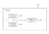
도 5는 다중 셀 기반 환경의 분산 안테나 시스템에서 셀 간 간섭을 제어하기 위한 단말(500)의 구성을 개략적으로 도시한 블록도이고, 도 6은 단말(500)의 프로세서(540)의 상세한구성을 도시한 블록도이다.5 is a block diagram schematically illustrating a configuration of a
도 5를 참조하면, 단말(500)은 수신기(510), 심볼 복조기(520), 수신 데이터 프로세서(530), 프로세서(540), 메모리(550), 전송 데이터 프로세서(560), 심볼 변조기(570) 및 송신기(580), 안테나(590)를 포함할 수 있다.5, a terminal 500 includes a
수신기(510)는 안테나(590)를 통해 서빙 기지국으로부터 하나 이상의 인접 셀에 대한 유효 안테나의 개수 정보, 상기 유효 안테나의 인덱스 정보 및 상기 각 인접 셀의 참조신호 패턴에 대한 정보를 수신할 수 있다.The
심볼 복조기(520)는 수신기(510)가 수신한 정보에 해당하는 데이터 심볼들에 대해 데이터 복조를 수행하고, 데이터 심볼 추정치를 획득하여 수신 데이터 프로세서(530)로 제공한다.The
프로세서(540)는 도 6을 참조하여 설명하면, 프로세서(540)는 간섭 레벨 측정 모듈(541), 간섭제한 요청 결정 모듈(542) 및 유효 안테나 결정 모듈(543)을 포함할 수 있다.The
간섭 레벨 측정 모듈(541)은 각 인접 셀 별로 분산되어 배치된 안테나 중 상기 단말(500)에 간섭을 미치는 안테나인 유효 안테나에 대한 개수 정보, 상기 유효 안테나의 인덱스 정보 및 각 인접 셀의 참조신호 패턴 정보 중 하나 이상을 이용하여 각 인접 셀의 간섭 레벨을 측정할 수 있다. 간섭 레벨 측정 모듈(541)은 각 인접 셀의 유효 안테나, 유효 안테나의 인덱스, 각 인접 셀의 참조신호 패턴 정보는 수신기(510)가 수신한 것을 이용할 수도 있고, 직접 간섭 레벨을 측정하여 파악한 각 인접 셀의 유효 안테나, 유효 안테나의 인덱스, 각 인접 셀의 참조신호 패턴 정보일 수도 있다. 간섭 레벨 측정 모듈(541)은 다중 셀 기반의 분산 안테나 시스템에서 하나 이상의 인접 셀의 간섭 레벨을 보다 정확하게 측정하기 위해서는 인접 셀들의 안테나 구성 정보가 필요하다. 안테나 구성 정보는 각 인접 셀에서의 유효 안테나의 개수 정보, 유효 안테나의 인덱스 정보, 및 각 인접 셀의 참조신호 패턴 정보 중 하나 이상이 포함할 수 있다. 이하에서 안테나 구성 정보에 대해 간략히 설명한다.The interference
1. 각 인접 셀 별로 유효 안테나 개수1. Number of effective antennas for each adjacent cell
분산 안테나 시스템에서, CoMP 동작을 수행하는 단말(500)은 자신에게 간섭을 미치는 각 인접 셀의 유효 안테나 개수에 대한 정보가 필요하다. 즉, 단말(500)의 간섭 레벨 측정 모듈(541)은 몇 개의 안테나가 실질적으로 간섭으로 작용하는 지에 대한 정보를 기반으로 유효 안테나 및 유효 안테나 개수에 해당하는 간섭을 측정하고, 간섭제한 요청 결정 모듈(542)은 각 인접 셀의 간섭 레벨을 사전에 설정된 임계값과 비교하여 상기 각 인접 셀에 간섭제한을 요청할지 여부를 결정하면, 송신기(580)는 안테나(590)를 통해 간섭제한 요청 지시(혹은 사일런싱 지시) 정보를 서빙 기지국으로 전송할 수 있다.In the distributed antenna system, the terminal 500 performing CoMP operation needs information on the number of effective antennas of each neighboring cell that interferes with itself. That is, the interference
도 7은 다중 셀 기반 분산 안테나 시스템에서 셀 간 간섭을 제어하기 위한 방법을 설명하기 위한 예시적인 도면이다.7 is an exemplary diagram illustrating a method for controlling inter-cell interference in a multi-cell based distributed antenna system.
도 7에 도시한 바와 같이, 각 4개의 분산 안테나를 가진 3개의 분산 안테나 시스템의 셀이 있다고 가정하자. 셀 A(서빙 셀)에 속한 단말(500)의 수신기(510)는 안테나(590)를 통해 셀 A의 분산 안테나 1번(Tx 1), 4번(Tx 4)으로 구성된 유효 안테나 그룹(710)으로부터 바람직한 신호를 수신할 수 있다. 이 경우, 단말(500)의 프로세서(540)가 2개 송신 안테나 기반의 코드북(codebook) 중 best PMI를 선택하면, 송신기(580)는 이를 서빙 셀에 전송한다.As shown in Fig. 7, assume that there are cells of three dispersion antenna systems each having four dispersion antennas. A
또한, 단말(500)은 셀 B로부터 2개의 분산 안테나로 구성된 유효 안테나 그룹(안테나 2번, 4번)(720)으로부터 강한 간섭을 받을 수 있다. 또한, 단말(500)은 셀 C로부터는 3개의 분산 안테나로 구성된 유효 안테나 그룹(안테나 1번, 3번, 4번)(730)으로부터 강한 간섭을 받는다.Also, the terminal 500 can receive strong interference from the effective antenna group (
간섭 레벨 측정 모듈(541)이 인접 셀(즉, 셀 B 및 셀 C)로부터의 간섭 레벨을 정확히 측정하여 단말(500)이 보다 정확한 간섭제한 지시(즉, 사일런싱 지시) 정보 보고를 수행하기 위해서는, 단말(500)은 각 셀로부터 자신에게 간섭을 미치고 있는 유효 안테나 수를 알고 있을 필요가 있다. 즉, 단말 1(510)의 간섭 레벨 측정 모듈(541)은 셀 B로부터 2개의 분산 안테나로 구성된 유효 안테나 그룹(720)으로부터 수신한 신호를 이용하여 간섭 정도(혹은, 간섭 레벨)를 측정할 수 있다. 마찬가지로, 간섭 레벨 측정 모듈(541)은 셀 C로부터의 3개의 분산 안테나로 구성된 유효 안테나 그룹(730)으로부터 수신한 신호를 이용하여 간섭 정도를 측정할 수 있다. 따라서, 단말 1(510)이 셀 B, 셀 C의 유효 안테나 개수에 대한 정보를 알면 보다 인접 셀에 대한 간섭 레벨의 측정이 정확하고 효율적이게 된다. 이를 통해, 셀 경계에 위치한 단말 1(510)에 대해 CoMP 동작을 수행하며 분산 안테나 시스템을 적용하고 있는 하나 이상의 인접 셀로부터의 간섭을 줄이고 제어할 수 있다.In order for the interference
(2) 유효 안테나 인덱스(2) Effective antenna index
단말 1(510)의 간섭 레벨 측정 모듈(541)이 효과적으로 인접 셀(예를 들어, 셀 B, 셀 C)의 간섭을 측정하기 위해서는 인접 셀의 유효 안테나 개수에 대한 정보 외에 유효 안테나 인덱스에 대한 정보도 필요할 수 있다. 각 셀의 각 안테나 포트(즉, 각 분산 안테나)는 서로 다른 시간, 주파수 영역(시분할 다중화(TDM), 주파수 분할 다중화(FDM), 코드 분할 다중화(CDM) 방식을 모두 포함)에서 참조신호를 전송할 수 있다. 따라서, 간섭 레벨 측정 모듈(541)은 단순히 인접 셀로부터 몇 개의 분산 안테나가 유효 안테나 그룹을 구성하고 있는지에 대한 정보만으로 정확하게 간섭을 측정하기가 힘들다. 따라서, 유효 안테나 개수에 덧붙여, 해당 안테나의 실질적인 인덱스에 대한 정보를 단말(500)이 공유하게 함으로써, 간섭 레벨 측정 모듈(541)이 해당 분산 안테나 수에 해당하는 간섭 레벨을 정확히 측정할 수 있다.In order for the interference
일 예로서, 도 7에 도시된 것과 같이, 각각 4개의 분산 안테나를 가진 3개의 분산 안테나 시스템 셀이 있다고 가정하자. 단말(500)은 인접 셀인 셀 B로부터 4개의 분산 안테나 중 안테나 2번, 4번으로 구성된 유효 안테나 그룹(720)으로부터 강한 간섭을 받고, 셀 C로부터는 4개의 분산 안테나 중 안테나 1번, 3번 및 4번으로 구성된 유효 안테나 그룹(730)으로부터 강한 간섭을 받는다. 간섭 레벨 측정 모듈(541)은 이러한 각 인접 셀의 유효 안테나 그룹(720, 730)에 속한 인덱스에 대한 정보를 알고 이용하는 경우 보다 더 정확한 인접 셀 간섭을 측정할 수 있다.As an example, assume that there are three distributed antenna system cells each having four dispersion antennas, as shown in Fig. The terminal 500 receives strong interference from the
(3) 간섭 등의 측정을 위한 인접 셀의 참조신호 패턴 정보(3) reference signal pattern information of an adjacent cell for measurement of interference and the like
간섭 레벨 측정 모듈(541)이 인접 셀들이 참조신호 패턴에 대한 정보를 이용하여 인접 셀들의 간섭 레벨을 측정하는 경우 보다 더 정확하게 측정할 수 있다. 이러한 인접 셀의 참조신호 패턴은 셀 ID(IDentifier)에 따라 사전에 정의되어 단말(500)이 암시적(implicitly)으로 알고 있거나 기지국이 단말(500)에게 명시적으로 직접 알려줄 수도 있다. 단말(500)의 간섭 레벨 측정 모듈(541)은 앞서 기술한 유효 안테나 수, 유효 안테나 인덱스, 및 인접 셀의 참조신호 패턴 정보 중 하나 이상의 정보에 기초하여 해당 인접 셀의 참조신호가 전송되는 시간, 주파수 영역을 측정함으로써 간섭의 세기를 정확하게 측정할 수 있고, 단말(500)은 간섭을 미치는 PMI에 대한 정보를 정확하게 얻을 수 있다. 이러한 과정을 통하여, 단말 1(510)은 분산 안테나 시스템을 적용하고 있는 다중 셀 환경하에 셀 간의 CS/CB 방식 또는 JP 방식을 효율적으로 수행할 수 있다.The interference
간섭제한 요청 결정 모듈(542)은 간섭 레벨 측정 모듈(541)에 의해 측정된 각 인접 셀의 간섭 레벨을 사전에 설정한 임계값과 비교하여 상기 각 인접 셀에 간섭제한을 요청할지 여부를 결정할 수 있다. 간섭제한 요청 결정 모듈(542)은 서빙 기지국에 간섭제한(즉, 사일런싱(silencing)) 요청에 대한 정보를 전송할지 여부를 사전에 설정된 임계값(예를 들어, 채널 품질, 간섭 레벨)에 기초하여 결정할 수 있다. 간섭제한 요청 결정 모듈(542)은 측정된 인접 셀의 간섭 값 등이 사전에 설정된 임계값을 초과하는 경우, 간섭 제한(즉, 사일런싱)을 서빙 기지국에 요청할 수 있다.The interference restriction
송신기(580)는 간섭제한을 요청하기로 결정한 하나 이상의 인접 셀의 정보를 서빙 기지국으로 전송할 수 있다. 이를 통해, 최소한의 상향링크 피드백 오버헤드로 셀 간 간섭이 완화 또는 제거될 수 있다.
분산 안테나 시스템을 위한 단말-특정 사일런싱(Terminal-Specific Silencing for Distributed Antenna SystemsUEUE--specificspecificsilencingsilencing))
(1) 기지국-중심 지시 방법(1) base station-centered indication method
도 8은 본 발명에 따른 기지국 장치의 구성을 나타낸 블록도이다.8 is a block diagram showing a configuration of a base station apparatus according to the present invention.
도 8을 참조하면, 기지국 장치(800)는 전송 데이터 프로세서(810), 심볼 변조기(820), 송신기(830), 프로세서(840), 메모리(850), 수신기(860), 심볼 복조기(870), 수신 데이터 프로세서(880) 및 안테나(890)를 포함할 수 있다.8, the
분산 안테나 시스템을 적용하고 있는 셀이 서로 협력하여 동작하는 경우(CoMP), 기지국(800)의 송신기(830)는 하나 이상의 인접 셀에 대한 안테나 구성 정보(유효 안테나 개수 정보, 유효 안테나 인덱스 정보)를 안테나(890)를 통해 단말(500)에게 전송해 줄 수 있다. 즉, 서빙 셀 A의 기지국(800)(즉, 서빙 기지국(800))이 단말(500)에 지시하는 기지국-중심 지시(eNB-centric indication) 방법을 고려한다. 서빙 셀 A의 기지국(800)이 단말(500)에게 인접 셀에 대한 유효 안테나 개수, 유효 안테나 인덱스 및 인접 셀의 참조신호 패턴 정보 중 하나 이상을 직접 알려주는 것이다. 이러한 서빙 기지국(800)은 안테나 구성 정보를 상위 계층 시그널링(higher layer signaling) 또는 L1/L2 제어 시그널링을 통해 단말 1(510)에게 알려줄 수 있다. 단말(500)의 간섭 레벨 측정 모듈(541)은 서빙 셀 A의 기지국(800)으로부터 수신한 안테나 구성 정보에 기초하여 인접 셀에 대한 간섭을 정확하고 효율적으로 측정할 수 있다. 간섭제한 요청 결정 모듈(542)은 이렇게 측정된 간섭 값이 특정 임계값을 초과하는 경우 인접 셀에 대한 사일런싱을 요청하기로 결정할 수 있다. 이 경우, 단말(500)의 송신기(580)는 단순히 1 비트 크기의 간섭제한 요청(즉, 사일런싱 지시) 정보만을 서빙 기지국(800)으로 전송할 수 있다. 추가적으로, 단말(500)의 송신기(580)는 각 인접 셀의 셀 ID 또는 셀 ID 인덱스를 함께 서빙 기지국(800)으로 피드백할 수 있다. 서빙 셀 A와 단말(500)이 인접 셀에 대한 정보를 공유하고 있고, 해당 인접 셀의 사일런싱 지시 정보 피드백 순서가 미리 정해져 있다면, 서빙 기지국(800)은 별도로 셀 ID 또는 셀 ID 인덱스 없이도 사일런싱 지시 정보만으로 어떠한 인접 셀에 관한 사일런싱 지시 정보인지 구분할 수 있다.(CoMP), the
예를 들어, 상기 도 7에 도시된 바와 같이 분산 안테나 시스템이 구성되어 있고 단말(500)은 사일런싱 지시 정보를 셀 B, 셀 C의 순서대로 피드백한다고 사전에 약속되어 있다고 가정하자. 단말(500)이 셀 B에 대해서만 사일런싱을 요청하는 경우, 단말(500)의 송신기(580)는 2진수 '10'과 같은 비트맵 형태로 표현되는 2 비트 크기 피드백(셀 B: 사일런싱 요청(silencing on), 셀 C: 사일런싱 비-요청(silencing off))으로 서빙 기지국(800) 또는 인접 셀 B에 전송해 줄 수 있다. 각 셀 간에는 유효 안테나에 대한 정보를 공유할 수 있기 때문에, 사일런싱 온/오프(on/off) 정보만으로 해당 유효 안테나에 대한 사일런싱을 수행할 수 있다. 즉, 셀 B는 단말(500)에게 간섭을 미치는 분산 안테나 2번, 4번(530)을 오프할 수 있다.For example, it is assumed that the distributed antenna system is configured as shown in FIG. 7, and the terminal 500 is previously promised to feed the silencing indication information in order of the cell B and the cell C. When the terminal 500 requests the cell B only for the silence, the
(2) 단말-중심 지시 방법(2) Terminal-centered instruction method
상술한 바와 같이, 서빙 기지국(800)이 인접 셀의 안테나 구성 정보 모두를 단말(500)에게 전송하는 기지국-중심 지시 방법에 대해 살펴보았다. 이와 달리, 인접 셀의 안테나 구성 정보 중 일부 정보만을 서빙 기지국(800)이 단말(500)에 지시하고, 나머지 안테나 구성 정보를 단말(500)이 직접 측정해서 결정할 수도 있다. 이러한 단말-중심 지시(UE-centric indication) 방법은 실질적으로 단말에게 간섭을 미치는 인접 셀의 유효 안테나에 대한 정확한 측정이 가능하다. 단말-중심 지시 방법에서는, 단말(500)이 자신에게 실질적인 영향을 미치는 인접 셀의 안테나 구성 정보를 결정하는 것이다. 이 방식에서 서빙 기지국(800)은 단말(500)에게 안테나 구성 정보 중 인접 셀의 참조신호 패턴 정보를 알려줄 수 있다. 인접 셀의 참조신호 패턴이 셀 ID에 따라 미리 정의되어있다면, 단말(500)의 프로세서(540)는 인접 셀의 셀 ID를 읽고 디코딩하여 인접 셀의 참조신호 패턴을 암시적으로 알 수 있다.As described above, the base station-centered indication method in which the serving
단말-중심 지시 방식에서, 단말(500)의 송신기(580)는 앞서 설명한 기지국-중심 지시 방식에서 단말의 피드백 정보인 사일런싱 지시 정보 외에 직접 측정하고 선택한 안테나 구성 정보를 서빙 기지국(800)에 전송할 수 있다. 이때, 단말 1의 프로세서(540)는 안테나 구성 정보 중 인접 셀의 참조신호 패턴을 제외한 유효 안테나 개수, 유효 안테나 인덱스 정보를 피드백하도록 제어하여, 송신기(580)은 유효 안테나 개수, 유효 안테나 인덱스 정보만을 서빙 기지국(800)에 전송할 수 있다. 단말(500)의 유효 안테나 결정 모듈(543)은 인접 셀의 참조신호 패턴에 기초하여 자신에게 가장 간섭을 많이 미치는 유효 안테나 수와 해당 안테나 인덱스를 측정하고 결정할 수 있다. 이때, 단말(500)의 유효 안테나 결정 모듈(543)은 유효 안테나 수와 해당 안테나 인덱스를 결정하기 위해 미리 정의된 임계값을 이용할 수 있다. 또한, 피드백 양을 줄이기 위해 미리 단말(500)이 간섭제한 목적으로 선택할 수 있는 유효 안테나 수가 사전에 정의되어 있을 수 있다. 이 경우, 를 정해두고 해당 안테나 인덱스만 서빙 기지국(800)으로 피드백할 수도 있다. 또는, 단말 1(510)이 사일런싱 지시 정보만 피드백하고 안테나 구성에 대한 정보는 측정에서만 사용할 수도 있다. 단말 1(510)이 사일런싱 지시 정보만을 피드백하는 경우, 유효 안테나 결정 모듈(543)은 사전에 정의된 수에 해당하는 만큼의 유효 안테나 및/또는 유효 안테나 인덱스를 결정하고, 송신기(580)는 사전에 정의된 수에 해당하는 만큼의 유효 안테나 및/또는 유효 안테나 인덱스 정보를 서빙 기지국(800)으로 피드백할 수 있다. 그러면, 서빙 기지국(800)은 해당 인접 셀에 특정 부대역/서브프레임(subband/subframe)에 전체 안테나에 대한 간섭제한(즉, 사일런싱)을 요청할 수 있다.
In the UE-centered indication scheme, the
분산 안테나 시스템을 위한 셀-특정 사일런싱(Cell-specific silencing for distributed antenna systemscellcell--specificspecificsilencingsilencing))
CoMP 동작을 수행하는 단말(500)이 서빙 셀 A로부터 충분한 채널 상태를 보장받지 못하거나 하나 이상의 인접 셀로부터 심한 간섭을 받고 있는 셀 경계에 위치하고 있다고 가정한다. 보통 이러한 셀 경계 단말(즉, 단말(500))은 저속으로 이동하며, 주로 랭크 1(rank 1)로 데이터를 수신할 수 있다. 이러한 CoMP 동작을 수행하는 셀 경계 단말(500)을 고려해보면, 단말의 피드백 정보에 기반한 방법은 상향링크 피드백 오버헤드와 백홀 오버헤드를 증가시키는 된다.It is assumed that the
따라서, 셀 배치(deployment) 시 사전에 정의된 빔 패턴(예를 들어, PMI)에 기인한 방법을 생각해 볼 수 있다. 초기 셀 배치(deployment) 시 각 셀 들의 특정 안테나로 구성된 유효 안테나와 유효 안테나의 빔(예를 들어, PMI)은 특정 방향성으로 미리 형성된다. 일반적으로, 랭크 1의 빔 패턴은 더 높은 랭크(higher rank)의 빔에 비해 보다 명확한 방향성을 가진다. 각 셀 들은 인접 셀 들 간에 서로 영향을 미치는 유효 안테나와 해당 유효 안테나의 특정 방향성을 갖는 빔 패턴에 대한 정보를 공유할 수 있다. 따라서, CoMP 동작을 수행하는 특정 셀(예를 들어, 셀 A)이 다른 특정 인접 셀(예를 들어, 셀 B)로부터 유효 안테나 또는 유효 안테나 빔 패턴의 제한을 요청받게 되면 그 특정 인접 셀에 간섭을 미치는 유효 안테나 또는 특정 셀로 향하는 방향성을 가진 유효 안테나 빔의 그룹을 제한함으로써 다른 특정 인접 셀(예를 들어, 셀 B)에 대한 간섭을 줄일 수 있다.Therefore, a method based on a predefined beam pattern (e.g., PMI) at the time of cell deployment can be considered. In the initial cell deployment, the effective antenna formed of a specific antenna of each cell and the beam of the effective antenna (for example, PMI) are formed in a predetermined direction. In general, the beam pattern of
즉, 기존의 방법은 인접 셀이 단말에 간섭을 주는 특정 PMI를 제한/추천 하거나 사일런싱하는 단말-특정 빔 제한(UE-specific beam restriction) 방식이라면, 이 방법은 인접 셀이 자신에게 방향성을 가지는 사전에 설정된 유효 안테나 또는 유효 안테나의 빔 패턴 그룹(예를 들어, PMI 세트)을 제한하는 셀-특정 사일런싱 방식이다. 셀 배치(deployment) 시, 셀 간의 서로 방향성을 가지는 빔 패턴 그룹은 일정한(uniform) 개수로 구성될 수도 있고, 특정 목적에 따라 일정하지 않게(non-uniform) 구성될 수도 있다. 즉, 인접 셀로부터 간섭을 받고 있는 단말(500)의 송신기(580)는 사일런싱 지시 정보를 서빙 기지국(800)으로 전송할 수 있다. 이러한 사일런싱 지시 정보의 전송으로, 인접 셀은 서빙 셀로 방향성을 가지고 있는 유효 안테나 그룹의 특정 PMI들을(빔 패턴 그룹) 제한하거나(예를 들어, 공간 분할 다중화(SDM)), 특정 부대역(subband)을 사일런싱(예를 들어, 주파수 분할 다중화(FDM)), 특정 시간 자원 영역을 사일런싱(예를 들어, 시분할 다중화(TDM))함으로써 단말(500)에 미치는 간섭을 줄일 수 있다.That is, if the existing method is a UE-specific beam restriction scheme in which a neighboring cell restricts / recommends or silences a specific PMI that interferes with the UE, Specific silencing scheme that limits a beam pattern group (e.g., a PMI set) of a pre-established effective antenna or an effective antenna. At the time of cell deployment, beam pattern groups having mutually directed directions among cells may be composed of a uniform number or may be non-uniform according to a specific purpose. That is, the
이러한 인접 셀에 대한 간섭제한은 특정 유효 안테나 그룹의 특정 PMI 세트로 제한될 수도 있고, 특정 유효 안테나 그룹 자체의 시간, 주파수 자원 영역에 대한 제한이 될 수도 있다. 이를 위해 앞서 언급한 안테나 구성 정보를 서빙 기지국(800)의 의 송신기(830)가 단말(500)에게 전송해 줄 수도 있고, 단말(500)은 서빙 기지국(800)의 안테나 구성 정보 지시 없이도 수행할 수도 있다. 본 발명에 따른 셀-특정 사일런싱 방법은 안테나 구성 정보 수신 없이 단말이 사일런싱 지시 정보를 피드백하는 것을 중점적으로 제안한다.The interference restriction on this neighboring cell may be limited to a specific PMI set of a specific effective antenna group or may be a time, frequency resource region limitation of the specific effective antenna group itself. For this, the
분산 안테나 시스템을 적용하고 CoMP 동작을 수행하는 셀이 3개 있다고 가정하자. 도 7을 참조하여 설명한다. 단말(500)은 셀 A에 속한 단말이다. 셀 B 와 셀 C는 전체 분산 안테나 중 각각 2번 안테나, 4번 안테나(Tx2, Tx4)와 1번 안테나, 3번 안테나, 4번 안테나(Tx 1, Tx 3, Tx4)로 이루어진 유효 안테나가 셀 A에 대한 실질적인 간섭을 미친다. 또한, 이러한 유효 안테나의 랭크 1의 빔 패턴 중 셀 A에 대한 방향성을 가진 빔 패턴 그룹 (W1, W2, W3) 와 (W6, W7, W8)을 각각 가진다. 이는 셀 배치 시 미리 정의된 값이다.Suppose that there are three cells that apply the distributed antenna system and perform the CoMP operation. Will be described with reference to FIG. The terminal 500 is a terminal belonging to the cell A. Cell B and cell C are arranged such that an effective antenna consisting of 2 antennas, 4 antennas (Tx2, Tx4) and 1 antenna, 3 antennas and 4 antennas (
셀 A에 속한 셀 경계 단말(500)이 셀 B, C로부터 극심한 간섭 신호를 받을 경우, 단말(500)의 송신기(580) 또는 서빙 셀 A의 기지국(800)의 송신기(830)가 인접 셀인 셀 B, C에 셀 A에 대한 실질적인 간섭을 일으키는 유효 안테나에 대한 간섭제한 요청(즉, 사일런싱 요청)을 피드백할 수 있다. 즉, 단말(500)의 송신기(580)는 서빙 기지국(800)으로 또는 인접 셀 B, C로, 각각 분산 안테나 중 2번 안테나, 4번 안테나(Tx2, 4)와 셀 C의 1번 안테나, 3번 안테나, 4번 안테나(Tx 1,3,4)로 이루어진 유효 안테나의 사용에 대한 제한을 요청하는 정보를 전송할 수 있다. 또는, 서빙 셀 A의 기지국(800)의 송신기(830)가 셀 B, C로 이러한 유효안테나 사용의 제한을 요청하는 정보를 전송할 수 있다.When the
도 9는 본 발명에 따른 인접 셀의 기지국(900) 장치의 구성을 도시한 블록도이다.9 is a block diagram showing a configuration of a
도 9를 참조하면, 도 8에 도시된 서빙 기지국(800)과 마찬가지로, 전송 데이터 프로세서(910), 심볼 변조기(920), 송신기(930), 프로세서(940), 메모리(850), 수신기(960), 심볼 복조기(970), 수신 데이터 프로세서(880), 안테나(990)를 포함할 수 있다. 인접 셀의 기지국(900)은 도 7에 도시한 바와 같은 셀 B 또는 셀 C의 기지국에 해당할 수 있다.9, a
수신기(960)는 안테나(990)를 통해 단말(500) 및/또는 단말(500)의 서빙 기지국(800)으로부터 간섭제한 요청(혹은 사일런싱 요청) 정보를 수신한다.The
프로세서(940)는 셀 A의 단말(500)에 간섭을 미치는 해당 유효 안테나를 통해 단말(500)이 사용하는 특정 부대역 또는 시간 자원 영역에서 일정 수준 이하의 전력으로 전송하도록 제어하거나, 데이터, 참조신호 등의 신호 전송 자체를 하지 않도록 제어할 수 있다. 만약, 인접 기지국(900)의 수신기(960)가 단말(500) 또는 서빙 기지국(800)으로부터 자신이 속한 셀의 유효 안테나 중 셀 A에 대한 방향성을 가지는 빔 패턴 그룹에 대한 제한 요청 정보를 수신한다면, 프로세서(940)는 해당 유효 안테나에 대한 빔 패턴 그룹인 (W1, W2, W3) 와 (W6, W7, W8)의 사용을 제한하도록 제어한다. 프로세서(940)는 이러한 특정 빔 패턴 그룹의 제한 혹은 특정 유효 안테나에 대한 사일런싱을 특정 서브프레임 또는 부대역에 적용하도록 제어할 수 있다. 이러한 특정 서브프레임 또는 부대역에 대한 간섭제한은 서빙 기지국(800)이 요청한 것이거나 인접 기지국(900)이 결정에 의한 것일 수도 있다.The
이하에서는 셀-특정 사일런싱 방식에 있어서, 피드백 정보 전송 방법과 트리거링(triggering)에 대한 방식을 설명한다.Hereinafter, a method for transmitting a feedback information and a method for triggering in a cell-specific silencing scheme will be described.
단말(500)은 특정 조건에 만족할 때, 셀-특정 사일런싱을 요청할 수 있다. 간섭 레벨 측정 모듈(541)에서 측정한 채널 상태가 사전에 정의된 임계값 보다 채널 상태가 만족하지 못할 때, 간섭제한 요청 결정 모듈(542)은 셀-특정 빔 회피(beam avoidance)를 요청할 것을 결정할 수 있다. 여기서, 간섭 레벨 측정 모듈(541)의 채널 상태의 판단은 인접 셀에 대한 측정을 수행했는지 여부에 따라 달라질 수 있다.The terminal 500 may request cell-specific silencing when certain conditions are met. When the channel condition measured by the interference
간섭 레벨 측정 모듈(541)이 인접 셀에 대한 측정을 수행하지 않은 경우에 대해 먼저 살펴본다. 간섭 레벨 측정 모듈(541)이 인접 셀에 대한 측정을 수행하지 않은 상태에서 단일 셀 기반의 통신을 수행할 경우, 간섭제한 요청 결정 모듈(542)은 CQI(Channel Quality Information) 등의 채널 상태와 서빙 셀을 제외한 나머지 셀로부터의 잡음 및 간섭 레벨(noise and interference level)을 기준으로 임계값과의 비교를 통해 셀-특정 간섭 제한(혹은 사일런싱) 요청할지 여부를 결정할 수 있다. 이 경우, 단말(500)의 송신기(580)는 서빙 셀 A의 기지국(800)에 인접 셀에 대한 간섭제한의 요청을 소정 비트 크기의 메시지(예를 들어, 1 비트) 등의 형태로 전송할 수 있다. 여기서, 단말(500)의 송신기(580)는 간섭제한의 요청 메시지를 PUCCH(Physical Uplink Control CHannel)나 PUSCH(Physical Uplink Shared CHannel), 또는 RRC(Radio Resource Control) 메시지 형태를 통해 서빙 기지국(800)에 전송함으로써 셀-특정 간섭제한 요청(사일런싱 요청)이 수행된다. 서빙 기지국(800)의 수신기(860)가 단말(500)로부터 셀-특정 간섭제한 요청을 수신하면, 프로세서(840)는 셀-특정 간섭제한 요청을 인접 기지국(900)에 전송하도록 제어할 수 있다.A case where the interference
다음으로, 간섭 레벨 측정 모듈(541)이 인접 셀에 대한 측정을 수행한 경우에 대해 먼저 살펴본다. 간섭 레벨 측정 모듈(541)이 인접 셀 B, C에 대한 측정을 수행한 후, 간섭제한 요청 결정 모듈(542)은 서빙 셀 A의 채널 상태와 더불어 CoMP 동작을 수행하는 인접 셀 B, C의 간섭 레벨과 임계값을 비교하여 인접 셀 B, C에 간섭제한(혹은 사일런싱) 요청을 할지 여부를 결정한다. 단말(500)이 안테나 구성 정보를 획득한 상황에서는, 간섭 레벨 측정 모듈(541)은 유효 안테나에 대한 보다 정확한 간섭을 측정할 수 있고, 안테나 구성 정보를 획득하지 못한 상황에서는, 인접 셀의 모든 안테나로부터 오는 간섭에 대한 대략적인 간섭 값을 계산한 후에, 간섭제한 요청 결정 모듈(542)은 이러한 대략적으로 계산된 간섭 레벨에 기초하여 간섭제한(혹은 사일런싱) 요청을 할지 여부를 결정한다. 이 경우는 다시 단말(500)의 간섭 레벨 측정 모듈(541)이 측정을 수행한 후, 송신기(580)가 안테나(590)를 통해 측정 정보를 서빙 기지국(800)에 전송하는 경우와 그렇지 않은 경우로 구분할 수 있다.Next, the case where the interference
먼저 간섭 레벨 측정 모듈(541)이 측정을 수행한 후, 송신기(580)가 측정 정보를 서빙 기지국(800)에 전송하는 경우를 생각해보자. 간섭 레벨 측정 모듈(541)은 인접 셀에 대해 RSRP(Reference Signal Received Power), RSRQ(Reference Signal Received Quality) 등의 형태로 측정을 수행하고, 송신기(580)는 안테나(590)를 통해 이러한 RSRP 또는 RSRQ와, 인접 셀의 셀 ID와 함께 서빙 기지국(800)에 전송할 수 있다. 서빙 기지국(800)의 수신기(860)가 이러한 인접 셀의 측정 정보를 수신하면, 서빙 기지국(800)은 인접 셀 ID 정보와 간섭 레벨 등의 정보를 알 수 있다.First, consider a case where the
간섭제한 요청 결정 모듈(542)은 간섭 레벨 측정 모듈(541)이 측정한 인접 셀들의 간섭 레벨 등을 임계값과의 비교를 통해 셀-특정 간섭제한(혹은 사일런싱) 요청을 할지 여부를 결정할 수 있다. 간섭제한 요청 결정 모듈(542)은 가장 크게 간섭을 미치는 하나 또는 그 이상의 인접 셀에 대해 간섭제한(혹은 사일런싱) 요청을 할 것을 결정할 수 있다. 간섭제한 요청 결정 모듈(542)이 하나 이상의 인접 셀에 대해 요청하기로 결정한 경우, 미리 정의된 N개의 인접 셀에 대해 간섭제한 요청을 하기로 결정할 수도 있고, 임계값을 넘는 인접 셀 전체에 대해 간섭제한 요청을 하기로 결정할 수도 있다.The interference restriction
마찬가지로, 단말(500)의 송신기(580)는 서빙 셀 A의 기지국(800)에 인접 셀에 대한 간섭제한의 요청을 소정 비트 크기의 메시지(예를 들어, 1 비트) 등의 형태로 전송할 수 있다. 여기서, 단말(500)의 송신기(580)는 간섭제한의 요청 메시지를 PUCCH(Physical Uplink Control CHannel)나 PUSCH(Physical Uplink Shared CHannel), 또는 RRC(Radio Resource Control) 메시지 형태를 통해 서빙 기지국(800)에 전송함으로써 셀-특정 간섭제한 요청(사일런싱 요청)이 수행된다. 단말(500)의 송신기(580)는 이러한 간섭제한 요청을 셀 ID나 셀 ID 인덱스에 관계없이 간섭 레벨이 높은 인접 셀 순으로 전송할 수도 있고, 제한하고자 하는 인접 셀의 셀 ID 인덱스와 함께 또는 셀 ID 인덱스만을 전송할 수도 있다.Similarly, the
서빙 기지국(800)의 수신기(860)가 단말(500)로부터 간섭 레벨 측정 모듈(541)이 측정한 정보를 수신하면, 프로세서(840)는 간섭 레벨 순으로 인접 셀에 대한 측정 정보를 분류할 수 있다. 이렇게 분류된 이 정보는 단말(500)과 서빙 기지국(800) 간의 별도의 시그널링 없이도 공유가 가능하다. 프로세서(840)는 이러한 분류 정보를 기반하여, 셀 ID 인덱스 없이 간섭 제한을 요청할 인접 셀을 결정하고, 송신기(830)는 결정된 인접 셀로 특정 유효 안테나, 빔 패턴 그룹에 대한 간섭제한을 요청하는 신호를 전송할 수 있다.When the
다음으로 간섭제한 요청 결정 모듈(542)이 측정을 수행한 후, 단말(500)이 측정 정보를 서빙 기지국(800)에 전송하지 않는 경우를 생각해보자. 이 경우, 단말(500)의 송신기(580)는 간섭제한 하고자 하는 인접 셀에 대한 셀 ID, 셀 ID 인덱스와 간섭제한 요청 메시지를 함께 전송하거나, 셀 ID, 셀 ID 인덱스만을 서빙 기지국(800)으로 전송할 수 있다. 또는, 서빙 기지국(800)과 단말(500)이 인접 셀에 대한 정보를 공유하고 있고, 해당 인접 셀의 간섭제한 요청 지시(혹은 사일런싱 요청 지시) 순서가 미리 정해져 있다면, 프로세서(840)은 별도 셀 ID, 셀 ID 인덱스 없이 간섭제한 요청 지시(혹은 사일런싱 요청 지시)만으로 어떠한 인접 셀에 관한 것인지 구분할 수 있다. 추가적으로, 프로세서(840)에 간섭제한 요청 지시와 더불어 해당 인접 셀에 대한 간섭 레벨도 전송하도록 제어하며, 송신기(830)는 간섭제한 요청 지시 정보 외에 해당 인접 셀에 대한 간섭 레벨 정보도 함께 전송할 수도 있다. 간섭제한 요청 결정 모듈(542)은 인접 셀에 대한 제한 요청 여부는 임계값과 측정값과의 비교를 통해 결정할 수 있다. 이러한 과정을 통하여, 단말(500)의 송신기(580)는 하나 또는 그 이상의 인접 셀로 간섭제한 요청(혹은 사일런싱 요청) 신호를 전송할 수 있다.Next, consider a case in which the
서빙 기지국(800)의 수신기(860)는 단말(500)로부터 간섭제한 요청 신호를 수신한 후, 송신기(830)는 해당 인접 셀에 특정 유효 안테나, 특정 빔 패턴 그룹에 대한 사용의 제한을 요청하는 신호를 전송할 수 있다. 다른 방법으로, 간섭제한 요청 결정 모듈(542)이 임계값과의 비교를 통해 간섭제한을 요청할지 여부를 결정한 후, 단말(500)의 송신기(580)는 서빙 기지국(800)에 특정 해당 인접 셀에 대한 요청이 아닌 불특정 인접 셀에 대한 간섭제한(혹은 사일런싱)을 요청하는 신호를 전송할 수 있다. 이 경우, 단말(500)의 송신기(580)는 셀 ID와 상관없이 하나의 제한 요청 메시지를 서빙 기지국(800)으로 전송하고, 서빙 기지국(800)의 프로세서(840)는 서빙 셀과 지리적으로 가까이 위치한 인접 셀에 대해 서빙 셀로의 방향성을 가진 하나 이상의 유효 안테나, 빔 패턴 그룹에 대한 사용 제한을 요청하도록 제어할 수 있다.After the
앞서 살펴본 셀-특정 간섭제한(혹은 사일런싱) 요청은 서빙 기지국(800)이 임의로 트리거링(triggering) 할 수도 있다. 단일 셀 기반이라는 가정에서, 서빙 기지국(800)의 수신기(860)는 단말(500)로부터의 단일 셀 기반 채널 정보를 주기적 또는 비 주기적으로 받는다. 서빙 기지국(800)의 프로세서(840)는 단말로부터 수신한 채널 정보와 사전에 정의된 임계값과의 비교를 통해 인접 셀에 임의로 간섭제한을 요청하기로 결정하도록 제어할 수 있다. 다른 방법으로, 서빙 기지국(800)의 수신기(860)가 단말(500)로부터 측정 정보를 수신한 경우, 서빙 기지국(800)의 프로세서(840)는 가장 간섭을 많이 미치는 인접 셀, 또는 간섭이 강한 특정 개수의 인접 셀, 또는 임계값을 초과하여 간섭을 미치는 인접 셀 들에 대해 자신의 셀에 대한 방향성을 가진 유효 안테나, 빔 패턴 그룹을 제한해 주도록 제어할 수 있다.The serving
이하에서는 기지국 간(혹은 셀 간)에 정보를 교환하는 방법에 대해 기술한다.Hereinafter, a method of exchanging information between base stations (or between cells) will be described.
단말(500)의 송신기(580)가 셀-특정 간섭제한(혹은 사일런싱)을 요청하거나 서빙 기지국(800)이 임의로 셀-특정 간섭제한(혹은 사일런싱)을 요청할 경우, 서빙 기지국(800)은 해당 인접 셀과 유효 안테나, 빔 패턴 그룹 제한에 대한 정보와 간섭 레벨 등의 관련 정보(associated information)를 주고 받을 수 있다. 이를 통해 셀 간에 효율적으로 셀-특정 간섭제한(혹은 사일런싱)의 요청이 수행될 수 있다.When the
서빙 기지국(800)의 프로세서(840)는 자신의 속한 셀에 대한 방향성을 가지는 유효 안테나, 빔 패턴 그룹을 인접 셀이 제한해 줄 것을 요청하는 메시지를 해당 인접 셀에 보내도록 제어한다. 인접 기지국(900)의 수신기(960)는 이러한 간섭제한 요청 메시지를 여러 셀로부터 수신하고, 프로세서(940)는 이러한 간섭제한 요청 메시지에 기초하여 해당 유효 안테나, 빔 패턴의 사용을 제한하도록 제어한다. 그러나, 인접 기지국(900)이 여러 셀로부터 간섭제한 요청을 받게 되면, 프로세서(940)는 어떤 유효 안테나, 빔 패턴을 제한하는 것이 가장 효율적인 것인지에 관한 랭킹 문제(ranking problem)를 해결할 필요가 있다.The
이를 해결하기 위해, 서빙 기지국(800)의 수신기(860)는 간섭제한 요청 메시지에 추가로 해당 인접 셀에 의해 발생하는 간섭 레벨 등에 대한 정보를 함께 수신할 수 있다. 프로세서(940)는 수신기(860)가 수신한 간섭제한 요청 메시지 및 인접 셀의 간섭 레벨 정보를 이용해서 어떤 유효 안테나, 빔 패턴을 제한하는 것이 가장 효율적인 것인지 결정할 수 있다.In order to solve this problem, the
도 10 및 도 11은 각각 기지국 간의 정보 교환을 하는 과정의 예를 나타낸 도면이다.10 and 11 are views showing an example of a process of exchanging information between BSs.
앞서 기술한 바와 같이, 기지국 간에 유효 안테나, 빔 패턴 그룹에 대한 제한 요청, 간섭 레벨 측정 정보와 같은 관련 정보(associated information) 교환뿐 아니라, 스케줄링 정보를 주고 받을 수 있다. 분산 안테나 시스템을 채용하고 있는 다중 셀 환경에서, 셀 A에 속한 기지국 A(1010), 셀 B에 속한 기지국 B(1020), 셀 C에 속한 기지국 C(1030)가 존재한다고 가정하자.As described above, scheduling information can be exchanged between base stations as well as exchange of associated information such as effective antennas, restriction requests for beam pattern groups, and interference level measurement information. Assume that in a multi-cell environment employing a distributed antenna system, a base station A 1010 belonging to cell A, a base station B 1020 belonging to cell B, and a base station C 1030 belonging to cell C are present.
기지국 A(1010)는 인접 기지국인 기지국 B(1020)과 기지국 C(1030)에 자신이 속한 셀 A로 간섭을 유발하는 특정 유효 안테나, 특정 빔 패턴 그룹에 대한 사용을 제한해 줄 것을 요청하는 신호를 전송하고, 기지국 C(1030)는 인접 기지국인 기지국 A(1010)과 기지국 B(1020)에 각각 셀 C로 간섭을 유발하는 특정 유효 안테나, 특정 빔 패턴 그룹에 대한 사용을 제한해 줄 것을 요청하는 신호를 전송할 수 있다. 이에 대해, 기지국 B(1020)는 기지국 A(1010) 및 기지국 C(1030)에 간섭 제한 요청에 대한 응답을 '예' 또는 '아니오'의 형식으로 각각 전송하고, 기지국 A(1010)는 기지국 C(1030)에, 기지국 C(1030)는 기지국 A(1010)에 간섭 제한 요청에 대한 응답을 '예' 또는 '아니오'의 형식으로 각각 전송해 줄 수 있다. 또는, 도 11에 도시한 바와 같이, 기지국 B(1020)는 기지국 A(1010)에 셀 A로 간섭을 유발하는 특정 유효 안테나, 특정 빔 패턴 그룹에 대해 사용을 J번째 서브프레임 또는 부대역에서 제한할 것을 알리는 신호를 전송하고, 기지국 C(1030)에 셀 C로 유발하는 특정 유효 안테나, 특정 빔 패턴 그룹의 사용을 K번째 서브프레임 또는 부대역에서 제한할 것을 알리는 신호를 전송해 줄 수 있다. 기지국 C(1030)는 기지국 A(1010)에 셀 A로 간섭을 유발하는 특정 유효 안테나, 특정 빔 패턴 그룹의 사용을 L번째 서브프레임 또는 부대역에서 제한할 것을 알리는 신호를 전송하고, 기지국 A(1010)는 기지국 C(1030)에게 셀 A로 간섭을 유발하는 특정 유효 안테나, 특정 빔 패턴 그룹의 사용을 M번째 서브프레임 또는 부대역에서 제한할 것을 알리는 신호를 전송해 줄 수 있다.The base station A 1010 transmits to the base station B 1020 and the base station C 1030 adjacent base stations a signal for requesting to restrict use of a specific beam pattern group, And the base station C 1030 transmits a request to the base station A 1010 and the base station B 1020, which are adjacent base stations, to limit the use of a specific effective antenna pattern for causing interference to the cell C, Lt; / RTI > In response, the base station B 1020 transmits a response to the interference restriction request to the base station A 1010 and the base station C 1030 in the form of 'yes' or 'no' The base station C 1030 may transmit the response to the interference restriction request to the base station A 1010 in the form of 'yes' or 'no', respectively. Alternatively, as shown in FIG. 11, the base station B 1020 may transmit to the base station A 1010 a specific effective antenna that causes interference to the cell A, and restricts the use of the specific beam pattern group in the Jth subframe or subband And transmits to the base station C 1030 a signal indicating that the specific effective antenna caused by the cell C and the use of the specific beam pattern group are limited in the Kth subframe or subband. The base station C 1030 transmits to the base station A 1010 a signal indicating that the use of the specific effective antenna pattern, the specific beam pattern group causing the interference to the cell A is restricted in the L th sub frame or the sub band, 1010 may transmit to the base station C 1030 a specific effective antenna that causes interference to cell A, or a signal to limit the use of a particular beam pattern group to the Mth subframe or subband.
특정 셀에 대해 유효 안테나, 빔 패턴 그룹의 사용을 전 대역 또는 전체 무선 프레임에 제한하는 경우, 상기 특정 셀 내의 단말의 성능에 많은 손실을 초래할 수 있다. 따라서, 효과적인 기지국 간의 시간, 주파수 자원 할당 및 전송 정보에 대한 스케줄링으로 인해 전송 자원을 효율적으로 사용할 수 있다. 즉, 특정 셀에 대한 제한을 특정 서브프레임 또는 부대역에 적용하는 스케줄링을 기지국 간에 공유함으로써, 서로 간섭을 일으키는 유효 안테나, 빔 패턴의 사용을 서브프레임, 부대역 단위로 효율적으로 수행할 수 있다.When the use of the effective antenna and the beam pattern group for a specific cell is limited to the entire band or the entire radio frame, the performance of the UE in the specific cell may be greatly damaged. Therefore, effective transmission resources can be efficiently used due to effective time base, frequency resource allocation, and scheduling for transmission information. That is, by sharing the scheduling for applying a restriction on a specific cell to a specific sub-frame or sub-band, it is possible to effectively use the effective antenna and the beam pattern, which cause interference with each other, in units of sub-frames and sub-bands.
기지국 간(1010, 1020, 1030) 간의 스케줄링 정보는 L1/L2 제어 정보로 X2 인터페이스를 통해 공유될 수도 있고, L3 RRC 접속 제어 정보로 공유될 수도 있다. 이러한 기지국 간의 스케줄링 정보를 공유 방법에 대해 이하에서 간략히 설명한다.The scheduling information between the base stations 1010, 1020, and 1030 may be shared through the X2 interface as L1 / L2 control information, or may be shared with the L3 RRC connection control information. A method of sharing the scheduling information among the base stations will be briefly described below.
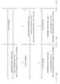
도 12는 인접 기지국인 기지국 2가 간섭제한 요청에 대해 스케줄링을 수행하여 기지국 간에 스케줄링 정보를 공유하는 과정의 예를 나타낸 도면이다.12 is a diagram illustrating an example of a process in which a
도 12를 참조하면, 기지국 1 및 기지국 3은 각각 단말 1, 단말 2로부터 특정 유효 안테나, 특정 빔 패턴 그룹에 대한 사용을 제한해 줄 것을 요청하는 신호를 수신한다. 그러면, 기지국 1 및 기지국 3은 각각 단말 1, 단말 3으로부터 요청받은 특정 유효 안테나, 특정 빔 패턴 그룹을 소정의 서브프레임 및/또는 부대역에서 사용을 제한해 줄 것을 요청하는 신호를 각각 인접 기지국인 기지국 2에 전송해 줄 수 있다. 이때, 기지국 1 및 기지국 3은 인접 기지국의 간섭 레벨 정보 등을 포함하는 관련 정보를 함께 각각 인접 기지국인 기지국 2에 전송해 줄 수 있다. 기지국 2의 프로세서는 기지국 1 및 기지국 3으로부터 수신한 간섭제한 요청 정보에 기초하여 스케줄링을 수행한다. 기지국 2의 프로세서는 관련 정보를 기지국 1 및 기지국 3으로부터 수신한 경우에는 관련 정보도 이용하여 스케줄링을 수행한다. 기지국 2의 프로세서는 스케줄링을 수행한 후, 예를 들어, 기지국 2의 송신기는 기지국 1에게 간섭제한 요청에 대해 간섭을 제한하도록 하겠다는 '예'라는 응답의 신호를 전송하지만, 기지국 3에게는 간섭제한 요청에 대해 '아니오'라는 응답의 신호를 전송할 수 있다. 기지국 2가 기지국 3의 간섭제한 요청을 거부할 경우, 차선책에 대한 제안 사항이 전달될 수도 있다. 즉, 기지국 2는 기지국 3이 간섭제한 요청을 한 특정 서브프레임 또는 부대역이 아닌, 차선의 다른 서브프레임 또는 부대역에서 유효 안테나, 빔 패턴 그룹을 사용하지 않겠다는 응답의 신호를 전송할 수 있다.Referring to FIG. 12, the
도 13은 인접 기지국인 기지국 2가 간섭제한 요청에 대해 스케줄링을 수행하여 기지국 간에 스케줄링 정보를 공유하는 과정의 다른 예를 나타낸 도면이다.FIG. 13 is a diagram illustrating another example of a process in which a
도 13을 참조하면, 기지국 1 및 기지국 3은 각각 단말 1, 단말 2로부터 특정 유효 안테나, 특정 빔 패턴 그룹에 대한 사용을 제한해 줄 것을 요청하는 신호를 수신한다. 즉, 단말 1 및 단말 3이 각각 스케줄링을 수행하여 특정 서브프레임 또는 부대역에서 특정 유효 안테나, 특정 빔 패턴 그룹의 사용을 제한해 줄 것을 요청하는 신호를 서빙 기지국인 기지국 1 및 기지국 3에 각각 전송할 수 있다. 그러면, 도 12에서와 달리, 기지국 1의 프로세서 및 기지국 3의 프로세서는 각각 단말 1, 단말 3으로부터 받은 간섭제한 요청에 기반하여 스케줄링을 수행한다. 기지국 1의 프로세서와 기지국 3의 프로세서는 자신이 속한 셀 내 여러 단말(예를 들어, 기지국 1은 단말 1, 기지국 3은 단말 3)로부터 수신한 스케줄링 정보를 취합한 뒤, 이 스케줄링 정보뿐만 아니라 관련 정보, 해당 인접 셀의 트래픽 등을 고려하여 스스로 유효 안테나, 빔 패턴 그룹에 대해 사용을 제한하는 스케줄링을 수행한다. 스케줄링을 수행한 후, 기지국 1 및 기지국 3은 스케줄링한 정보를 피드백 정보로 각각 기지국 2로 전송한다. 이때, 기지국 1 및 기지국 3은 피드백 정보 외에 인접 기지국에 대한 간섭 레벨 정보를 포함하는 관련 정보를 더 포함하여 전송할 수도 있다.Referring to FIG. 13, the
그 후, 기지국 2의 프로세서는 수신한 정보를 기반으로 효율적으로 스케줄링을 수행할 수 있다. 기지국 2의 프로세서는 수신기 수신한 피드백 정보에 기초하여 스케줄링을 수행한다. 스케줄링 수행 후, 예를 들어, 기지국 2의 송신기는 기지국 1에게 간섭제한 요청에 대해 간섭을 제한하도록 하겠다는 '예'라는 응답의 신호를 전송하지만, 기지국 3에게는 간섭제한 요청에 대해 '아니오'라는 응답의 신호를 전송할 수 있다. 기지국 2가 기지국 3의 간섭제한 요청을 거부할 경우, 차선책에 대한 제안 사항이 전달될 수도 있다. 즉, 기지국 2는 기지국 3이 간섭제한 요청을 한 특정 서브프레임 또는 부대역이 아닌, 차선의 다른 서브프레임 또는 부대역에서 유효 안테나, 빔 패턴 그룹을 사용하지 않겠다는 응답의 신호를 전송할 수 있다.Thereafter, the processor of the
도 14는 인접 기지국인 기지국 2가 간섭제한 요청에 대해 스케줄링을 수행하여 기지국 간에 스케줄링 정보를 공유하는 과정의 다른 예를 나타낸 도면이다.FIG. 14 is a diagram illustrating another example of a process in which a
도 14를 참조하면, 단말 1 및 단말 3이 각각 스케줄링을 수행하여 특정 서브프레임 또는 부대역에서 특정 유효 안테나, 특정 빔 패턴 그룹의 사용을 제한해 줄 것을 요청하는 신호를 서빙 기지국인 기지국 1 및 기지국 3에 각각 전송할 수 있다. 그 후, 단말 1의 서빙 기지국인 기지국 1과 단말 3의 서빙 기지국인 기지국 3은 각각 단말 1, 단말 3으로부터 수신한 피드백 정보(특정 서브프레임 또는 부대역에서 특정 유효 안테나, 특정 빔 패턴 그룹 사용을 제한할 것을 스케줄링한 정보)를 어떠한 가공 없이 그대로 인접 기지국인 기지국 2로 전송할 수 있다. 기지국 2의 프로세서는 기지국 1 및 기지국 3으로부터 수신한 간섭제한 요청 등에 기초하여 효율적으로 스케줄링을 수행할 수 있다. 스케줄링 수행 후, 예를 들어, 기지국 2의 송신기는 기지국 1에게 간섭제한 요청에 대해 간섭을 제한하도록 하겠다는 '예'라는 응답의 신호를 전송하지만, 기지국 3에게는 간섭제한 요청에 대해 '아니오'라는 응답의 신호를 전송할 수 있다. 기지국 2가 기지국 3의 간섭제한 요청을 거부할 경우, 차선책에 대한 제안 사항이 전달될 수도 있다. 즉, 기지국 2는 기지국 3이 간섭제한 요청을 한 특정 서브프레임 또는 부대역이 아닌, 차선의 다른 서브프레임 또는 부대역에서 유효 안테나, 빔 패턴 그룹을 사용하지 않겠다는 응답의 신호를 전송할 수 있다.Referring to FIG. 14, a
이상에서는, 서빙 셀에 대해 특정 방향성을 가지는 인접 셀의 유효 안테나/빔 패턴 그룹을 제한하는 간섭제한(혹은 사일런싱)에 대해 설명하였다. 그러나, 본 발명에 따른 셀 간 간섭 제한 방법은 다중 셀 간의 조인트 프로세싱(JP) 방식에도 적용 가능하다. 다중 셀 간의 데이터 공유를 하지 않고 각각 독립적으로 전송하는 경우에는, 서빙 셀로 향하는 방향성을 가진 유효 안테나, 빔 패턴이 간섭으로 작용한다. 그러나, 다중 셀 간의 데이터 공유를 통해 신호를 강화시키는 JP 방식의 경우에는, 서빙 셀로 향하는 방향성을 가진 유효 안테나, 빔 패턴 그룹이 best PMI 그룹이 될 수 있다. 따라서, 인접 셀의 유효 안테나, 빔 패턴 그룹을 제한하는 간섭제한(혹은 사일런싱) 기술은 다중 셀 간에 데이터를 공유함으로써 셀 경계 단말의 신호를 강화하는 JP 기술로 적용될 수 있다.In the above description, the interference restriction (or silencing) for limiting the effective antenna / beam pattern group of the adjacent cell having a specific directionality to the serving cell has been described. However, the inter-cell interference limiting method according to the present invention is also applicable to the joint processing (JP) method between multiple cells. In the case of independently transmitting data without sharing data among a plurality of cells, an effective antenna with a directivity toward a serving cell, a beam pattern acts as an interference. However, in the case of the JP scheme for enhancing the signal through data sharing among multiple cells, the effective antenna and the beam pattern group having the directivity toward the serving cell can be the best PMI group. Therefore, an interference limiting (or silencing) technique for limiting the effective antenna and beam pattern group of a neighboring cell can be applied as a JP technique for enhancing a signal of a cell boundary terminal by sharing data among multiple cells.
본 발명에서는 단말(500)이 인접 셀의 간섭 상황에서 N(≥1) 비트의 간섭제한 지시 정보를 피드백함으로써 N개의 인접 셀에 대한 간섭제한(혹은 사일런싱)을 요청하는 것이다. 앞서 기술한 발명에서는 간섭을 미치는 각 인접 셀 별로 단말이 1 비트 크기의 간섭제한 지시 정보를 전송하는 것을 기술하였다. 인접 셀로부터 간섭을 받는 단말(500)이 유효 안테나에 대한 사용을 제한해 줄 것을 요청하는 방법 외에, 간섭 레벨 측정 모듈(541)이 인접 셀로부터 오는 전체 안테나 각각에 대해 간섭을 측정하고, 간섭제한 요청 결정 모듈(542)이 간섭을 많이 미치는 안테나와 해당 안테나의 인덱스를 결정하고, 송신기(580)는 서빙 기지국(800)으로 해당 안테나의 인덱스 정보를 포함하여 간섭제한 요청(혹은 사일런싱 요청)하는 신호를 전송할 수도 있다.In the present invention, the
즉, 간섭제한 요청 결정 모듈(542)은 미리 정의된 한정된 개수의 안테나 인덱스를 결정하는데, 이때 특정 임계값을 초과하는 간섭을 가지는 안테나 인덱스를 피드백하도록 결정할 수 있다. 이러한 방법은 위에서 기술한 단말-특정 사일런싱과 셀-특정 사일런싱 방식에 모두 적용될 수 있다.That is, interference restriction
또한, 인접 셀의 간섭을 완전히 제거하기 위해 인접 셀의 어떠한 신호 전송도 제한하는 방법과 인접 기지국이 사일런싱 요청에 대해 해당 유효 안테나의 전송 전력을 일정 수준 이하로 낮추는 방법 외에 단말(500)의 프로세서(540)가 해당 인접 셀의 유효 안테나에 대한 전송 전력을 결정해서 이를 피드백할 수 있다. 이값은 양자화된 N(N≥1) 비트로 표현할 수 있다. 이러한 단말(500)에 의한 인접 셀 안테나의 전송 전력 결정은 유효 안테나 그룹에 대한 지시 외에, 앞서 설명한 단말(500)의 간섭제한 요청 결정 모듈(542)이 간섭을 미치는 인접 셀의 안테나 인덱스를 직접 결정하고, 송신기(580)가 피드백하는 방법에도 적용될 수 있다. 이러한 방법은 위에서 기술한 단말-특정 사일런싱과 셀-특정 사일런싱 방식에 모두 적용될 수 있다.In addition, there is a method of restricting any signal transmission of the adjacent cell to completely eliminate the interference of the adjacent cell, a method of reducing the transmission power of the corresponding effective antenna to a certain level or lower in response to the silent request from the adjacent base station, (540) may determine the transmission power for the effective antenna of the neighboring cell and feed back the determined transmission power. This value can be expressed by quantized N (N? 1) bits. The determination of the transmission power of a neighboring cell antenna by the terminal 500 may be performed by directly determining an antenna index of a neighboring cell that interferes with the interference restriction
상술한 바와 같이 개시된 본 발명의 바람직한 실시예들에 대한 상세한 설명은 당업자가 본 발명을 구현하고 실시할 수 있도록 제공되었다. 상기에서는 본 발명의 바람직한 실시예들을 참조하여 설명하였지만, 해당 기술 분야의 숙련된 당업자는 본 발명의 영역으로부터 벗어나지 않는 범위 내에서 본 발명을 다양하게 수정 및 변경시킬 수 있음을 이해할 수 있을 것이다. 예를 들어, 당업자는 상술한 실시예들에 기재된 각 구성을 서로 조합하는 방식으로 이용할 수 있다.DETAILED DESCRIPTION OF THE PREFERRED EMBODIMENTS The foregoing description of the preferred embodiments of the invention disclosed herein has been presented to enable any person skilled in the art to make and use the present invention. While the present invention has been particularly shown and described with reference to preferred embodiments thereof, it will be understood by those skilled in the art that various changes and modifications may be made therein without departing from the spirit and scope of the invention as defined by the appended claims. For example, those skilled in the art can utilize each of the configurations described in the above-described embodiments in a manner of mutually combining them.
따라서, 본 발명은 여기에 나타난 실시형태들을 제한하는 것이 아니라, 여기서 개시된 원리들 및 신규한 특징들과 일치하는 최광의 범위를 부여하려는 것이다.Accordingly, the present invention is not intended to be limited to the embodiments shown herein but is to be accorded the widest scope consistent with the principles and novel features disclosed herein.
Claims (20)
Translated fromKorean소정의 서브밴드 단위 당 이웃 셀이 겪는 간섭의 레벨을 나타내는 제1 정보, 상기 이웃 셀의 전송이 제한되는 사일런스 서브프레임(silenced subframe)에 대한 제2 정보 및 상기 이웃 셀의 다수의 안테나들 중에서 특정 안테나의 개수를 나타내는 제3 정보를 포함하는 제1 메시지를 상기 이웃 셀로부터 수신하는 단계; 및
상기 제1 정보, 상기 제2 정보 및 상기 제3 정보에 기초하여 상기 기지국이 서빙하는 단말에 대한 하향링크 전송 또는 상향링크 수신을 스케줄하는 단계를 포함하는, 방법.A method for performing inter-cell interference coordination in a wireless communication system,
A first information indicating a level of interference experienced by a neighboring cell per predetermined subband unit, second information on a silenced subframe in which transmission of the neighboring cell is restricted, Receiving from the neighboring cell a first message comprising third information indicative of the number of antennas; And
And scheduling downlink transmission or uplink reception to the terminal served by the base station based on the first information, the second information, and the third information.
상기 이웃 셀이 서빙하는 제2 단말 또는 상기 이웃 셀로부터 간섭 제한을 요청하는 제2 메시지를 수신하는 단계; 및
상기 제2 단말에게 간섭을 미치는 안테나로 사전에 정의되어 있는 유효 안테나 또는 상기 유효 안테나의 빔 패턴 그룹에 대해 특정 시간 또는 주파수 영역에서 오프하거나 혹은 사용을 제한하도록 제어하는 단계를 더 포함하고,
상기 간섭 제한의 요청은 상기 제2 단말의 채널 상태 및 상기 이웃 셀을 제외한 다른 셀들의 잡음 및 간섭 레벨을 사전에 설정된 임계값과 비교하여 결정된 것을 특징으로 하는 방법.8. The method of claim 7,
Receiving a second message requesting interference restriction from a neighboring cell or a second terminal serving the neighboring cell; And
Further comprising the step of controlling to turn off or limit the use of a beam pattern group of the effective antenna or the effective antenna predefined by the antenna that interferes with the second terminal in the specific time or frequency domain,
Wherein the request for interference restriction is determined by comparing a channel state of the second terminal and a noise and interference level of other cells except for the neighboring cell with a preset threshold value.
상기 제2 메시지는 PUCCH(Physical Uplink Control CHannel), PUSCH(Physical Uplink Shared CHannel) 또는 상위 계층 시그널링을 통하여 수신되는 것을 특징으로 하는 방법.9. The method of claim 8,
Wherein the second message is received via a Physical Uplink Control Channel (PUCCH), a Physical Uplink Shared CHannel (PUSCH), or higher layer signaling.
소정의 서브밴드 단위 당 상기 이웃 셀에 의해 야기되는 간섭에 대한 제4 정보를 더 포함하는, 방법.8. The method of claim 7,
And fourth information on interference caused by the neighboring cells per predetermined subband unit.
X2 인터페이스 시그널링을 통해서 수신되는, 방법.8. The method of claim 7,
X2 interface signaling.
소정의 서브밴드 단위 당 이웃 셀이 겪는 간섭의 레벨을 나타내는 제1 정보, 상기 이웃 셀의 전송이 제한되는 사일런스 서브프레임(silenced subframe)에 대한 제2 정보 및 상기 이웃 셀의 다수의 안테나들 중에서 특정 안테나의 개수를 나타내는 제3 정보를 포함하는 제1 메시지를 상기 이웃 셀로부터 수신하는 수신기; 및
상기 제1 정보, 상기 제2 정보 및 상기 제3 정보에 기초하여 상기 기지국이 서빙하는 단말에 대한 하향링크 전송 또는 상향링크 수신을 스케줄하는 프로세서를 포함하는, 기지국.1. A base station for performing inter-cell interference coordination in a wireless communication system,
A first information indicating a level of interference experienced by a neighboring cell per predetermined subband unit, second information on a silenced subframe in which transmission of the neighboring cell is restricted, A receiver for receiving from the neighboring cell a first message including third information indicative of the number of antennas; And
And a scheduler for scheduling a downlink transmission or an uplink reception to a terminal served by the base station based on the first information, the second information, and the third information.
소정의 서브밴드 단위 당 상기 이웃 셀에 의해 야기되는 간섭에 대한 제4 정보를 더 포함하는, 기지국.13. The method of claim 12,
And fourth information on interference caused by the neighboring cells per predetermined subband unit.
X2 인터페이스 시그널링을 통해서 수신되는, 기지국.13. The method of claim 12,
X2 interface signaling.
Priority Applications (3)
| Application Number | Priority Date | Filing Date | Title |
|---|---|---|---|
| US13/582,962US9203591B2 (en) | 2010-03-05 | 2011-03-04 | Apparatus and method for performing inter-cell interference coordination in a wireless communication system |
| PCT/KR2011/001515WO2011108889A2 (en) | 2010-03-05 | 2011-03-04 | Apparatus and method for controlling inter-cell interference |
| US14/927,094US20160065335A1 (en) | 2010-03-05 | 2015-10-29 | Apparatus and method for controlling inter-cell interference |
Applications Claiming Priority (2)
| Application Number | Priority Date | Filing Date | Title |
|---|---|---|---|
| US31070910P | 2010-03-05 | 2010-03-05 | |
| US61/310,709 | 2010-03-05 |
Publications (2)
| Publication Number | Publication Date |
|---|---|
| KR20110101033A KR20110101033A (en) | 2011-09-15 |
| KR101674958B1true KR101674958B1 (en) | 2016-11-10 |
Family
ID=44953268
Family Applications (1)
| Application Number | Title | Priority Date | Filing Date |
|---|---|---|---|
| KR1020100088509AActiveKR101674958B1 (en) | 2010-03-05 | 2010-09-09 | The apparatus and method for controlling inter-cell interference |
Country Status (3)
| Country | Link |
|---|---|
| US (2) | US9203591B2 (en) |
| KR (1) | KR101674958B1 (en) |
| WO (1) | WO2011108889A2 (en) |
Families Citing this family (210)
| Publication number | Priority date | Publication date | Assignee | Title |
|---|---|---|---|---|
| US8605803B2 (en)* | 2010-03-15 | 2013-12-10 | Industrial Technology Research Institute | Methods and apparatus for reducing uplink multi-base station interference |
| US9307431B2 (en) | 2010-04-13 | 2016-04-05 | Qualcomm Incorporated | Reporting of channel properties in heterogeneous networks |
| US20110250919A1 (en) | 2010-04-13 | 2011-10-13 | Qualcomm Incorporated | Cqi estimation in a wireless communication network |
| US8886250B2 (en) | 2010-06-18 | 2014-11-11 | Qualcomm Incorporated | Channel quality reporting for different types of subframes |
| US9515773B2 (en)* | 2010-04-13 | 2016-12-06 | Qualcomm Incorporated | Channel state information reporting in a wireless communication network |
| US9350475B2 (en) | 2010-07-26 | 2016-05-24 | Qualcomm Incorporated | Physical layer signaling to user equipment in a wireless communication system |
| US20120134284A1 (en)* | 2010-06-24 | 2012-05-31 | Telefonaktiebolaget Lm Ericsson (Publ) | Methods and Nodes in a Wireless Communication Network |
| US9136953B2 (en)* | 2010-08-03 | 2015-09-15 | Qualcomm Incorporated | Interference estimation for wireless communication |
| US8891438B2 (en)* | 2010-09-08 | 2014-11-18 | Intel Corporation | Packet-data network and methods for RAN-agnostic multimedia content distribution |
| US8854998B2 (en)* | 2011-02-11 | 2014-10-07 | Mediatek Inc. | Method of UE RSRQ measurement precaution for interference coordination |
| WO2012116732A1 (en)* | 2011-03-01 | 2012-09-07 | Nokia Siemens Networks Oy | Sharing radio resources between access nodes with different access restrictions |
| US8855000B2 (en) | 2011-04-28 | 2014-10-07 | Qualcomm Incorporated | Interference estimation using data traffic power and reference signal power |
| WO2013025236A1 (en)* | 2011-08-12 | 2013-02-21 | Intel Corporation | System and method of uplink power control in a wireless communication system |
| CN103024751B (en)* | 2011-09-26 | 2016-01-27 | 华为技术有限公司 | Interference control method and apparatus |
| US9496929B2 (en) | 2012-04-06 | 2016-11-15 | Lg Electronics Inc. | Coordinated beamforming method in wireless access system, and apparatus therefor |
| KR102108070B1 (en)* | 2012-05-21 | 2020-05-08 | 엘지전자 주식회사 | Method for sharing wireless resource information in multi-cell wireless communication system and apparatus for same |
| US20140022988A1 (en)* | 2012-07-20 | 2014-01-23 | Alexei Davydov | User equipment and method for antenna port quasi co-location signaling in coordinated multi-point operations |
| CN103686824B (en)* | 2012-09-11 | 2016-12-21 | 普天信息技术研究院有限公司 | A kind of downlink edge user determines method |
| US9042253B2 (en)* | 2012-09-24 | 2015-05-26 | Alcatel Lucent | Resource allocation in heterogeneous LTE networks via CSMA-based algorithms |
| CN104737619B (en) | 2012-09-28 | 2018-12-25 | 英特尔公司 | Permanent online bearer for small data transmission in L TE system |
| EP2901603B1 (en) | 2012-09-28 | 2019-11-13 | Intel Corporation | Dynamic hybrid automatic repeat request-acknowledgement (harq-ack) transmission with enhanced physical downlink control channels |
| EP2901740B1 (en) | 2012-09-28 | 2019-03-06 | Intel Corporation | Discontinuous reception (drx) enhancements in lte systems |
| WO2014052905A1 (en) | 2012-09-28 | 2014-04-03 | Yiu Candy | Rsrp mobility state estimation for cellular device |
| US10009065B2 (en) | 2012-12-05 | 2018-06-26 | At&T Intellectual Property I, L.P. | Backhaul link for distributed antenna system |
| US9113347B2 (en) | 2012-12-05 | 2015-08-18 | At&T Intellectual Property I, Lp | Backhaul link for distributed antenna system |
| KR102169959B1 (en) | 2013-03-19 | 2020-10-26 | 엘지전자 주식회사 | Method by which terminal transmits and receives signal in multi cell-based wireless communication system, and device for same |
| KR101664876B1 (en)* | 2013-05-14 | 2016-10-12 | 삼성전자 주식회사 | Method and apparatus of interference measurement for inter-cell interference mitigation in tdd wireless communication system |
| US9999038B2 (en) | 2013-05-31 | 2018-06-12 | At&T Intellectual Property I, L.P. | Remote distributed antenna system |
| US9525524B2 (en) | 2013-05-31 | 2016-12-20 | At&T Intellectual Property I, L.P. | Remote distributed antenna system |
| CN105379332B (en)* | 2013-07-23 | 2019-04-19 | 华为技术有限公司 | Data transmission method and device |
| US20160295597A1 (en)* | 2013-07-26 | 2016-10-06 | Intel IP Corporation | Signaling interference information for user equipment assistance |
| WO2015020404A1 (en)* | 2013-08-05 | 2015-02-12 | 삼성전자 주식회사 | Method and apparatus for transmitting and receiving reference signal through beam grouping in wireless communication system |
| KR102223418B1 (en)* | 2013-09-24 | 2021-03-05 | 소니 주식회사 | Communication control device, communication control method, terminal device, and information processing device |
| US8897697B1 (en) | 2013-11-06 | 2014-11-25 | At&T Intellectual Property I, Lp | Millimeter-wave surface-wave communications |
| KR102180959B1 (en)* | 2013-12-09 | 2020-11-19 | 삼성전자주식회사 | Adaptive beam sweeping coordination method and apparatus in a wireless communication system |
| US9209902B2 (en) | 2013-12-10 | 2015-12-08 | At&T Intellectual Property I, L.P. | Quasi-optical coupler |
| US20150189667A1 (en)* | 2013-12-27 | 2015-07-02 | Lg Electronics Inc. | Method and apparatus for performing interference cancellation |
| KR20150086992A (en) | 2014-01-21 | 2015-07-29 | 한국전자통신연구원 | Method and apparatus for analyzing interference in the time-space dimension |
| US9596014B2 (en)* | 2014-01-28 | 2017-03-14 | Lg Electronics Inc. | Method and apparatus for cancelling interference |
| CN104822147B (en)* | 2014-01-30 | 2018-12-07 | 上海诺基亚贝尔股份有限公司 | Method and apparatus for X2 signaling |
| US9692101B2 (en) | 2014-08-26 | 2017-06-27 | At&T Intellectual Property I, L.P. | Guided wave couplers for coupling electromagnetic waves between a waveguide surface and a surface of a wire |
| US9768833B2 (en) | 2014-09-15 | 2017-09-19 | At&T Intellectual Property I, L.P. | Method and apparatus for sensing a condition in a transmission medium of electromagnetic waves |
| US10063280B2 (en) | 2014-09-17 | 2018-08-28 | At&T Intellectual Property I, L.P. | Monitoring and mitigating conditions in a communication network |
| US9628854B2 (en) | 2014-09-29 | 2017-04-18 | At&T Intellectual Property I, L.P. | Method and apparatus for distributing content in a communication network |
| EP3203661B1 (en) | 2014-10-01 | 2020-01-01 | LG Electronics Inc. | Method and apparatus for transmitting interference cancellation information for inter-cell interference cancellation |
| US9615269B2 (en) | 2014-10-02 | 2017-04-04 | At&T Intellectual Property I, L.P. | Method and apparatus that provides fault tolerance in a communication network |
| US9685992B2 (en) | 2014-10-03 | 2017-06-20 | At&T Intellectual Property I, L.P. | Circuit panel network and methods thereof |
| US9503189B2 (en) | 2014-10-10 | 2016-11-22 | At&T Intellectual Property I, L.P. | Method and apparatus for arranging communication sessions in a communication system |
| US9762289B2 (en) | 2014-10-14 | 2017-09-12 | At&T Intellectual Property I, L.P. | Method and apparatus for transmitting or receiving signals in a transportation system |
| US9973299B2 (en) | 2014-10-14 | 2018-05-15 | At&T Intellectual Property I, L.P. | Method and apparatus for adjusting a mode of communication in a communication network |
| US9564947B2 (en) | 2014-10-21 | 2017-02-07 | At&T Intellectual Property I, L.P. | Guided-wave transmission device with diversity and methods for use therewith |
| US9577306B2 (en) | 2014-10-21 | 2017-02-21 | At&T Intellectual Property I, L.P. | Guided-wave transmission device and methods for use therewith |
| US9520945B2 (en) | 2014-10-21 | 2016-12-13 | At&T Intellectual Property I, L.P. | Apparatus for providing communication services and methods thereof |
| US9769020B2 (en) | 2014-10-21 | 2017-09-19 | At&T Intellectual Property I, L.P. | Method and apparatus for responding to events affecting communications in a communication network |
| US9627768B2 (en) | 2014-10-21 | 2017-04-18 | At&T Intellectual Property I, L.P. | Guided-wave transmission device with non-fundamental mode propagation and methods for use therewith |
| US9312919B1 (en) | 2014-10-21 | 2016-04-12 | At&T Intellectual Property I, Lp | Transmission device with impairment compensation and methods for use therewith |
| US9653770B2 (en) | 2014-10-21 | 2017-05-16 | At&T Intellectual Property I, L.P. | Guided wave coupler, coupling module and methods for use therewith |
| US9780834B2 (en) | 2014-10-21 | 2017-10-03 | At&T Intellectual Property I, L.P. | Method and apparatus for transmitting electromagnetic waves |
| US9742462B2 (en) | 2014-12-04 | 2017-08-22 | At&T Intellectual Property I, L.P. | Transmission medium and communication interfaces and methods for use therewith |
| US9654173B2 (en) | 2014-11-20 | 2017-05-16 | At&T Intellectual Property I, L.P. | Apparatus for powering a communication device and methods thereof |
| US9800327B2 (en) | 2014-11-20 | 2017-10-24 | At&T Intellectual Property I, L.P. | Apparatus for controlling operations of a communication device and methods thereof |
| US9997819B2 (en) | 2015-06-09 | 2018-06-12 | At&T Intellectual Property I, L.P. | Transmission medium and method for facilitating propagation of electromagnetic waves via a core |
| US9954287B2 (en) | 2014-11-20 | 2018-04-24 | At&T Intellectual Property I, L.P. | Apparatus for converting wireless signals and electromagnetic waves and methods thereof |
| US9544006B2 (en) | 2014-11-20 | 2017-01-10 | At&T Intellectual Property I, L.P. | Transmission device with mode division multiplexing and methods for use therewith |
| US10243784B2 (en) | 2014-11-20 | 2019-03-26 | At&T Intellectual Property I, L.P. | System for generating topology information and methods thereof |
| US9461706B1 (en) | 2015-07-31 | 2016-10-04 | At&T Intellectual Property I, Lp | Method and apparatus for exchanging communication signals |
| US10009067B2 (en) | 2014-12-04 | 2018-06-26 | At&T Intellectual Property I, L.P. | Method and apparatus for configuring a communication interface |
| US10340573B2 (en) | 2016-10-26 | 2019-07-02 | At&T Intellectual Property I, L.P. | Launcher with cylindrical coupling device and methods for use therewith |
| US9680670B2 (en) | 2014-11-20 | 2017-06-13 | At&T Intellectual Property I, L.P. | Transmission device with channel equalization and control and methods for use therewith |
| CN107211289B (en)* | 2015-01-29 | 2022-03-01 | 索尼公司 | Apparatus and method |
| US20160226603A1 (en)* | 2015-01-30 | 2016-08-04 | Alex Stephenne | Method and system for validating interfering signals |
| US10144036B2 (en) | 2015-01-30 | 2018-12-04 | At&T Intellectual Property I, L.P. | Method and apparatus for mitigating interference affecting a propagation of electromagnetic waves guided by a transmission medium |
| US9876570B2 (en) | 2015-02-20 | 2018-01-23 | At&T Intellectual Property I, Lp | Guided-wave transmission device with non-fundamental mode propagation and methods for use therewith |
| US9749013B2 (en) | 2015-03-17 | 2017-08-29 | At&T Intellectual Property I, L.P. | Method and apparatus for reducing attenuation of electromagnetic waves guided by a transmission medium |
| US9705561B2 (en) | 2015-04-24 | 2017-07-11 | At&T Intellectual Property I, L.P. | Directional coupling device and methods for use therewith |
| US10224981B2 (en) | 2015-04-24 | 2019-03-05 | At&T Intellectual Property I, Lp | Passive electrical coupling device and methods for use therewith |
| US9948354B2 (en) | 2015-04-28 | 2018-04-17 | At&T Intellectual Property I, L.P. | Magnetic coupling device with reflective plate and methods for use therewith |
| US9793954B2 (en) | 2015-04-28 | 2017-10-17 | At&T Intellectual Property I, L.P. | Magnetic coupling device and methods for use therewith |
| US9871282B2 (en) | 2015-05-14 | 2018-01-16 | At&T Intellectual Property I, L.P. | At least one transmission medium having a dielectric surface that is covered at least in part by a second dielectric |
| US9748626B2 (en) | 2015-05-14 | 2017-08-29 | At&T Intellectual Property I, L.P. | Plurality of cables having different cross-sectional shapes which are bundled together to form a transmission medium |
| US9490869B1 (en) | 2015-05-14 | 2016-11-08 | At&T Intellectual Property I, L.P. | Transmission medium having multiple cores and methods for use therewith |
| US10679767B2 (en) | 2015-05-15 | 2020-06-09 | At&T Intellectual Property I, L.P. | Transmission medium having a conductive material and methods for use therewith |
| US10650940B2 (en) | 2015-05-15 | 2020-05-12 | At&T Intellectual Property I, L.P. | Transmission medium having a conductive material and methods for use therewith |
| US9917341B2 (en) | 2015-05-27 | 2018-03-13 | At&T Intellectual Property I, L.P. | Apparatus and method for launching electromagnetic waves and for modifying radial dimensions of the propagating electromagnetic waves |
| US9912381B2 (en) | 2015-06-03 | 2018-03-06 | At&T Intellectual Property I, Lp | Network termination and methods for use therewith |
| US10103801B2 (en) | 2015-06-03 | 2018-10-16 | At&T Intellectual Property I, L.P. | Host node device and methods for use therewith |
| US10348391B2 (en) | 2015-06-03 | 2019-07-09 | At&T Intellectual Property I, L.P. | Client node device with frequency conversion and methods for use therewith |
| US10812174B2 (en) | 2015-06-03 | 2020-10-20 | At&T Intellectual Property I, L.P. | Client node device and methods for use therewith |
| US10154493B2 (en) | 2015-06-03 | 2018-12-11 | At&T Intellectual Property I, L.P. | Network termination and methods for use therewith |
| US9866309B2 (en) | 2015-06-03 | 2018-01-09 | At&T Intellectual Property I, Lp | Host node device and methods for use therewith |
| US9913139B2 (en) | 2015-06-09 | 2018-03-06 | At&T Intellectual Property I, L.P. | Signal fingerprinting for authentication of communicating devices |
| US9608692B2 (en) | 2015-06-11 | 2017-03-28 | At&T Intellectual Property I, L.P. | Repeater and methods for use therewith |
| US10142086B2 (en) | 2015-06-11 | 2018-11-27 | At&T Intellectual Property I, L.P. | Repeater and methods for use therewith |
| US9820146B2 (en) | 2015-06-12 | 2017-11-14 | At&T Intellectual Property I, L.P. | Method and apparatus for authentication and identity management of communicating devices |
| US9667317B2 (en) | 2015-06-15 | 2017-05-30 | At&T Intellectual Property I, L.P. | Method and apparatus for providing security using network traffic adjustments |
| US9640850B2 (en) | 2015-06-25 | 2017-05-02 | At&T Intellectual Property I, L.P. | Methods and apparatus for inducing a non-fundamental wave mode on a transmission medium |
| US9865911B2 (en) | 2015-06-25 | 2018-01-09 | At&T Intellectual Property I, L.P. | Waveguide system for slot radiating first electromagnetic waves that are combined into a non-fundamental wave mode second electromagnetic wave on a transmission medium |
| US9509415B1 (en) | 2015-06-25 | 2016-11-29 | At&T Intellectual Property I, L.P. | Methods and apparatus for inducing a fundamental wave mode on a transmission medium |
| US10148016B2 (en) | 2015-07-14 | 2018-12-04 | At&T Intellectual Property I, L.P. | Apparatus and methods for communicating utilizing an antenna array |
| US10044409B2 (en) | 2015-07-14 | 2018-08-07 | At&T Intellectual Property I, L.P. | Transmission medium and methods for use therewith |
| US9628116B2 (en) | 2015-07-14 | 2017-04-18 | At&T Intellectual Property I, L.P. | Apparatus and methods for transmitting wireless signals |
| US10033107B2 (en) | 2015-07-14 | 2018-07-24 | At&T Intellectual Property I, L.P. | Method and apparatus for coupling an antenna to a device |
| US10033108B2 (en) | 2015-07-14 | 2018-07-24 | At&T Intellectual Property I, L.P. | Apparatus and methods for generating an electromagnetic wave having a wave mode that mitigates interference |
| US10341142B2 (en) | 2015-07-14 | 2019-07-02 | At&T Intellectual Property I, L.P. | Apparatus and methods for generating non-interfering electromagnetic waves on an uninsulated conductor |
| US9882257B2 (en) | 2015-07-14 | 2018-01-30 | At&T Intellectual Property I, L.P. | Method and apparatus for launching a wave mode that mitigates interference |
| US9847566B2 (en) | 2015-07-14 | 2017-12-19 | At&T Intellectual Property I, L.P. | Method and apparatus for adjusting a field of a signal to mitigate interference |
| US9853342B2 (en) | 2015-07-14 | 2017-12-26 | At&T Intellectual Property I, L.P. | Dielectric transmission medium connector and methods for use therewith |
| US9836957B2 (en) | 2015-07-14 | 2017-12-05 | At&T Intellectual Property I, L.P. | Method and apparatus for communicating with premises equipment |
| US10170840B2 (en) | 2015-07-14 | 2019-01-01 | At&T Intellectual Property I, L.P. | Apparatus and methods for sending or receiving electromagnetic signals |
| US10320586B2 (en) | 2015-07-14 | 2019-06-11 | At&T Intellectual Property I, L.P. | Apparatus and methods for generating non-interfering electromagnetic waves on an insulated transmission medium |
| US10205655B2 (en) | 2015-07-14 | 2019-02-12 | At&T Intellectual Property I, L.P. | Apparatus and methods for communicating utilizing an antenna array and multiple communication paths |
| US9722318B2 (en) | 2015-07-14 | 2017-08-01 | At&T Intellectual Property I, L.P. | Method and apparatus for coupling an antenna to a device |
| US9793951B2 (en) | 2015-07-15 | 2017-10-17 | At&T Intellectual Property I, L.P. | Method and apparatus for launching a wave mode that mitigates interference |
| US9608740B2 (en) | 2015-07-15 | 2017-03-28 | At&T Intellectual Property I, L.P. | Method and apparatus for launching a wave mode that mitigates interference |
| US10090606B2 (en) | 2015-07-15 | 2018-10-02 | At&T Intellectual Property I, L.P. | Antenna system with dielectric array and methods for use therewith |
| US9871283B2 (en) | 2015-07-23 | 2018-01-16 | At&T Intellectual Property I, Lp | Transmission medium having a dielectric core comprised of plural members connected by a ball and socket configuration |
| US10784670B2 (en) | 2015-07-23 | 2020-09-22 | At&T Intellectual Property I, L.P. | Antenna support for aligning an antenna |
| US9749053B2 (en) | 2015-07-23 | 2017-08-29 | At&T Intellectual Property I, L.P. | Node device, repeater and methods for use therewith |
| US9912027B2 (en) | 2015-07-23 | 2018-03-06 | At&T Intellectual Property I, L.P. | Method and apparatus for exchanging communication signals |
| US9948333B2 (en) | 2015-07-23 | 2018-04-17 | At&T Intellectual Property I, L.P. | Method and apparatus for wireless communications to mitigate interference |
| US9967173B2 (en) | 2015-07-31 | 2018-05-08 | At&T Intellectual Property I, L.P. | Method and apparatus for authentication and identity management of communicating devices |
| US9735833B2 (en) | 2015-07-31 | 2017-08-15 | At&T Intellectual Property I, L.P. | Method and apparatus for communications management in a neighborhood network |
| US10020587B2 (en) | 2015-07-31 | 2018-07-10 | At&T Intellectual Property I, L.P. | Radial antenna and methods for use therewith |
| US9698877B2 (en)* | 2015-08-02 | 2017-07-04 | Intel Corporation | Apparatus, system and method of single-user (SU) multi-in-multi-out (MIMO) communication |
| US9904535B2 (en) | 2015-09-14 | 2018-02-27 | At&T Intellectual Property I, L.P. | Method and apparatus for distributing software |
| US9705571B2 (en) | 2015-09-16 | 2017-07-11 | At&T Intellectual Property I, L.P. | Method and apparatus for use with a radio distributed antenna system |
| US10051629B2 (en) | 2015-09-16 | 2018-08-14 | At&T Intellectual Property I, L.P. | Method and apparatus for use with a radio distributed antenna system having an in-band reference signal |
| US10009063B2 (en) | 2015-09-16 | 2018-06-26 | At&T Intellectual Property I, L.P. | Method and apparatus for use with a radio distributed antenna system having an out-of-band reference signal |
| US10136434B2 (en) | 2015-09-16 | 2018-11-20 | At&T Intellectual Property I, L.P. | Method and apparatus for use with a radio distributed antenna system having an ultra-wideband control channel |
| US10079661B2 (en) | 2015-09-16 | 2018-09-18 | At&T Intellectual Property I, L.P. | Method and apparatus for use with a radio distributed antenna system having a clock reference |
| US10009901B2 (en) | 2015-09-16 | 2018-06-26 | At&T Intellectual Property I, L.P. | Method, apparatus, and computer-readable storage medium for managing utilization of wireless resources between base stations |
| US9769128B2 (en) | 2015-09-28 | 2017-09-19 | At&T Intellectual Property I, L.P. | Method and apparatus for encryption of communications over a network |
| US9729197B2 (en) | 2015-10-01 | 2017-08-08 | At&T Intellectual Property I, L.P. | Method and apparatus for communicating network management traffic over a network |
| US10074890B2 (en) | 2015-10-02 | 2018-09-11 | At&T Intellectual Property I, L.P. | Communication device and antenna with integrated light assembly |
| US9882277B2 (en) | 2015-10-02 | 2018-01-30 | At&T Intellectual Property I, Lp | Communication device and antenna assembly with actuated gimbal mount |
| US9876264B2 (en) | 2015-10-02 | 2018-01-23 | At&T Intellectual Property I, Lp | Communication system, guided wave switch and methods for use therewith |
| US10355367B2 (en) | 2015-10-16 | 2019-07-16 | At&T Intellectual Property I, L.P. | Antenna structure for exchanging wireless signals |
| US10665942B2 (en) | 2015-10-16 | 2020-05-26 | At&T Intellectual Property I, L.P. | Method and apparatus for adjusting wireless communications |
| US10051483B2 (en) | 2015-10-16 | 2018-08-14 | At&T Intellectual Property I, L.P. | Method and apparatus for directing wireless signals |
| WO2017071734A1 (en)* | 2015-10-27 | 2017-05-04 | Sony Mobile Communications, Inc. | Pilot resource allocation for a mimo system |
| WO2017074488A1 (en) | 2015-10-27 | 2017-05-04 | Intel IP Corporation | Devices and methods for robust measurement and data receiving |
| US10708016B2 (en)* | 2015-12-14 | 2020-07-07 | Qualcomm Incorporated | Reference signals for estimating mixed interference |
| US11122547B2 (en)* | 2015-12-29 | 2021-09-14 | Telecom Italia S.P.A. | System and method for allowing cooperation between a plurality of radio nodes in a telecommunication network |
| US9912419B1 (en) | 2016-08-24 | 2018-03-06 | At&T Intellectual Property I, L.P. | Method and apparatus for managing a fault in a distributed antenna system |
| US9860075B1 (en) | 2016-08-26 | 2018-01-02 | At&T Intellectual Property I, L.P. | Method and communication node for broadband distribution |
| US10291311B2 (en) | 2016-09-09 | 2019-05-14 | At&T Intellectual Property I, L.P. | Method and apparatus for mitigating a fault in a distributed antenna system |
| US11032819B2 (en) | 2016-09-15 | 2021-06-08 | At&T Intellectual Property I, L.P. | Method and apparatus for use with a radio distributed antenna system having a control channel reference signal |
| US10340600B2 (en) | 2016-10-18 | 2019-07-02 | At&T Intellectual Property I, L.P. | Apparatus and methods for launching guided waves via plural waveguide systems |
| US10135146B2 (en) | 2016-10-18 | 2018-11-20 | At&T Intellectual Property I, L.P. | Apparatus and methods for launching guided waves via circuits |
| US10135147B2 (en) | 2016-10-18 | 2018-11-20 | At&T Intellectual Property I, L.P. | Apparatus and methods for launching guided waves via an antenna |
| US9876605B1 (en) | 2016-10-21 | 2018-01-23 | At&T Intellectual Property I, L.P. | Launcher and coupling system to support desired guided wave mode |
| US9991580B2 (en) | 2016-10-21 | 2018-06-05 | At&T Intellectual Property I, L.P. | Launcher and coupling system for guided wave mode cancellation |
| US10374316B2 (en) | 2016-10-21 | 2019-08-06 | At&T Intellectual Property I, L.P. | System and dielectric antenna with non-uniform dielectric |
| US10811767B2 (en) | 2016-10-21 | 2020-10-20 | At&T Intellectual Property I, L.P. | System and dielectric antenna with convex dielectric radome |
| US10312567B2 (en) | 2016-10-26 | 2019-06-04 | At&T Intellectual Property I, L.P. | Launcher with planar strip antenna and methods for use therewith |
| US10224634B2 (en) | 2016-11-03 | 2019-03-05 | At&T Intellectual Property I, L.P. | Methods and apparatus for adjusting an operational characteristic of an antenna |
| US10225025B2 (en) | 2016-11-03 | 2019-03-05 | At&T Intellectual Property I, L.P. | Method and apparatus for detecting a fault in a communication system |
| US10291334B2 (en) | 2016-11-03 | 2019-05-14 | At&T Intellectual Property I, L.P. | System for detecting a fault in a communication system |
| US10498044B2 (en) | 2016-11-03 | 2019-12-03 | At&T Intellectual Property I, L.P. | Apparatus for configuring a surface of an antenna |
| US10340603B2 (en) | 2016-11-23 | 2019-07-02 | At&T Intellectual Property I, L.P. | Antenna system having shielded structural configurations for assembly |
| US10090594B2 (en) | 2016-11-23 | 2018-10-02 | At&T Intellectual Property I, L.P. | Antenna system having structural configurations for assembly |
| US10340601B2 (en) | 2016-11-23 | 2019-07-02 | At&T Intellectual Property I, L.P. | Multi-antenna system and methods for use therewith |
| US10178445B2 (en) | 2016-11-23 | 2019-01-08 | At&T Intellectual Property I, L.P. | Methods, devices, and systems for load balancing between a plurality of waveguides |
| US10535928B2 (en) | 2016-11-23 | 2020-01-14 | At&T Intellectual Property I, L.P. | Antenna system and methods for use therewith |
| US10361489B2 (en) | 2016-12-01 | 2019-07-23 | At&T Intellectual Property I, L.P. | Dielectric dish antenna system and methods for use therewith |
| US10305190B2 (en) | 2016-12-01 | 2019-05-28 | At&T Intellectual Property I, L.P. | Reflecting dielectric antenna system and methods for use therewith |
| US10727599B2 (en) | 2016-12-06 | 2020-07-28 | At&T Intellectual Property I, L.P. | Launcher with slot antenna and methods for use therewith |
| US10819035B2 (en) | 2016-12-06 | 2020-10-27 | At&T Intellectual Property I, L.P. | Launcher with helical antenna and methods for use therewith |
| US10382976B2 (en) | 2016-12-06 | 2019-08-13 | At&T Intellectual Property I, L.P. | Method and apparatus for managing wireless communications based on communication paths and network device positions |
| US10326494B2 (en) | 2016-12-06 | 2019-06-18 | At&T Intellectual Property I, L.P. | Apparatus for measurement de-embedding and methods for use therewith |
| US10439675B2 (en) | 2016-12-06 | 2019-10-08 | At&T Intellectual Property I, L.P. | Method and apparatus for repeating guided wave communication signals |
| US10755542B2 (en) | 2016-12-06 | 2020-08-25 | At&T Intellectual Property I, L.P. | Method and apparatus for surveillance via guided wave communication |
| US10135145B2 (en) | 2016-12-06 | 2018-11-20 | At&T Intellectual Property I, L.P. | Apparatus and methods for generating an electromagnetic wave along a transmission medium |
| US9927517B1 (en) | 2016-12-06 | 2018-03-27 | At&T Intellectual Property I, L.P. | Apparatus and methods for sensing rainfall |
| US10694379B2 (en) | 2016-12-06 | 2020-06-23 | At&T Intellectual Property I, L.P. | Waveguide system with device-based authentication and methods for use therewith |
| US10637149B2 (en) | 2016-12-06 | 2020-04-28 | At&T Intellectual Property I, L.P. | Injection molded dielectric antenna and methods for use therewith |
| US10020844B2 (en) | 2016-12-06 | 2018-07-10 | T&T Intellectual Property I, L.P. | Method and apparatus for broadcast communication via guided waves |
| US10359749B2 (en) | 2016-12-07 | 2019-07-23 | At&T Intellectual Property I, L.P. | Method and apparatus for utilities management via guided wave communication |
| US10027397B2 (en) | 2016-12-07 | 2018-07-17 | At&T Intellectual Property I, L.P. | Distributed antenna system and methods for use therewith |
| US10168695B2 (en) | 2016-12-07 | 2019-01-01 | At&T Intellectual Property I, L.P. | Method and apparatus for controlling an unmanned aircraft |
| US10243270B2 (en) | 2016-12-07 | 2019-03-26 | At&T Intellectual Property I, L.P. | Beam adaptive multi-feed dielectric antenna system and methods for use therewith |
| US10139820B2 (en) | 2016-12-07 | 2018-11-27 | At&T Intellectual Property I, L.P. | Method and apparatus for deploying equipment of a communication system |
| US10389029B2 (en) | 2016-12-07 | 2019-08-20 | At&T Intellectual Property I, L.P. | Multi-feed dielectric antenna system with core selection and methods for use therewith |
| US10547348B2 (en) | 2016-12-07 | 2020-01-28 | At&T Intellectual Property I, L.P. | Method and apparatus for switching transmission mediums in a communication system |
| US9893795B1 (en) | 2016-12-07 | 2018-02-13 | At&T Intellectual Property I, Lp | Method and repeater for broadband distribution |
| US10446936B2 (en) | 2016-12-07 | 2019-10-15 | At&T Intellectual Property I, L.P. | Multi-feed dielectric antenna system and methods for use therewith |
| US10601494B2 (en) | 2016-12-08 | 2020-03-24 | At&T Intellectual Property I, L.P. | Dual-band communication device and method for use therewith |
| US10326689B2 (en) | 2016-12-08 | 2019-06-18 | At&T Intellectual Property I, L.P. | Method and system for providing alternative communication paths |
| US9998870B1 (en) | 2016-12-08 | 2018-06-12 | At&T Intellectual Property I, L.P. | Method and apparatus for proximity sensing |
| US10069535B2 (en) | 2016-12-08 | 2018-09-04 | At&T Intellectual Property I, L.P. | Apparatus and methods for launching electromagnetic waves having a certain electric field structure |
| US10103422B2 (en) | 2016-12-08 | 2018-10-16 | At&T Intellectual Property I, L.P. | Method and apparatus for mounting network devices |
| US10530505B2 (en) | 2016-12-08 | 2020-01-07 | At&T Intellectual Property I, L.P. | Apparatus and methods for launching electromagnetic waves along a transmission medium |
| US10938108B2 (en) | 2016-12-08 | 2021-03-02 | At&T Intellectual Property I, L.P. | Frequency selective multi-feed dielectric antenna system and methods for use therewith |
| US9911020B1 (en) | 2016-12-08 | 2018-03-06 | At&T Intellectual Property I, L.P. | Method and apparatus for tracking via a radio frequency identification device |
| US10916969B2 (en) | 2016-12-08 | 2021-02-09 | At&T Intellectual Property I, L.P. | Method and apparatus for providing power using an inductive coupling |
| US10777873B2 (en) | 2016-12-08 | 2020-09-15 | At&T Intellectual Property I, L.P. | Method and apparatus for mounting network devices |
| US10411356B2 (en) | 2016-12-08 | 2019-09-10 | At&T Intellectual Property I, L.P. | Apparatus and methods for selectively targeting communication devices with an antenna array |
| US10389037B2 (en) | 2016-12-08 | 2019-08-20 | At&T Intellectual Property I, L.P. | Apparatus and methods for selecting sections of an antenna array and use therewith |
| US10340983B2 (en) | 2016-12-09 | 2019-07-02 | At&T Intellectual Property I, L.P. | Method and apparatus for surveying remote sites via guided wave communications |
| US10264586B2 (en) | 2016-12-09 | 2019-04-16 | At&T Mobility Ii Llc | Cloud-based packet controller and methods for use therewith |
| US9838896B1 (en) | 2016-12-09 | 2017-12-05 | At&T Intellectual Property I, L.P. | Method and apparatus for assessing network coverage |
| US9973940B1 (en) | 2017-02-27 | 2018-05-15 | At&T Intellectual Property I, L.P. | Apparatus and methods for dynamic impedance matching of a guided wave launcher |
| US10298293B2 (en) | 2017-03-13 | 2019-05-21 | At&T Intellectual Property I, L.P. | Apparatus of communication utilizing wireless network devices |
| US10652775B2 (en)* | 2017-03-14 | 2020-05-12 | Qualcomm Incorporated | Techniques for mitigating interference for transmissions of a periodic multi-beam discovery reference signal |
| US10673674B2 (en)* | 2017-07-12 | 2020-06-02 | Qualcomm Incorporated | Techniques and apparatuses for multiplexing schemes for millimeter wave downlink single carrier waveforms |
| CN109391997B (en)* | 2017-08-04 | 2022-11-04 | 华为技术有限公司 | Method, equipment and system for coordinating interference among cells and reporting measurement |
| US11785637B2 (en)* | 2020-04-29 | 2023-10-10 | Qualcomm Incorporated | Multiple channel state feedback reports for MU-MIMO scheduling assistance |
| JP7501670B2 (en)* | 2021-01-07 | 2024-06-18 | 日本電信電話株式会社 | Distributed antenna system, wireless communication method, and central station |
| EP4120578A1 (en)* | 2021-07-15 | 2023-01-18 | Koninklijke KPN N.V. | Beam optimization based on signal measurements in neighboring cells |
| GB2640133A (en)* | 2024-04-03 | 2025-10-15 | Nokia Technologies Oy | Inter-cell interference coordination |
Citations (1)
| Publication number | Priority date | Publication date | Assignee | Title |
|---|---|---|---|---|
| US20090197588A1 (en)* | 2008-02-01 | 2009-08-06 | Qualcomm Incorporated | Backhaul signaling for interference avoidance |
Family Cites Families (15)
| Publication number | Priority date | Publication date | Assignee | Title |
|---|---|---|---|---|
| US6953468B2 (en)* | 2001-06-13 | 2005-10-11 | Cordis Neurovascular, Inc. | Occluding vasculature of a patient using embolic coil with improved platelet adhesion |
| US20060247715A1 (en)* | 2005-04-29 | 2006-11-02 | Youker Nick A | Method and apparatus for an implantable pulse generator with a stacked battery and capacitor |
| US8195097B2 (en)* | 2006-09-08 | 2012-06-05 | Qualcomm Incorporated | Serving sector interference broadcast and corresponding RL traffic power control |
| US8848619B2 (en)* | 2007-11-27 | 2014-09-30 | Qualcomm Incorporated | Interface management in a wireless communication system using subframe time reuse |
| KR101119249B1 (en)* | 2008-03-26 | 2012-03-19 | 서강대학교산학협력단 | Signal control apparatus and method for distributed antenna system |
| EP2258896A4 (en)* | 2008-03-27 | 2012-06-20 | Kurita Water Ind Ltd | POLYMER FIBER MATERIAL, PROCESS FOR PRODUCING THE SAME, AND FILTER FOR FILTERING A FLUID |
| KR20090103661A (en)* | 2008-03-28 | 2009-10-01 | 엘지전자 주식회사 | Method for avoiding inter-cell interference in a multi-cell environment |
| US8340605B2 (en) | 2008-08-06 | 2012-12-25 | Qualcomm Incorporated | Coordinated transmissions between cells of a base station in a wireless communications system |
| US8472963B2 (en) | 2008-08-13 | 2013-06-25 | Ntt Docomo, Inc. | Variable coordination pattern approach for improving performance in multi-cell or multi-antenna environments |
| EP2230874B1 (en)* | 2009-03-17 | 2016-12-28 | Alcatel Lucent | Method for scheduling terminals in a radio communication network, and corresponding base station |
| US8538482B2 (en)* | 2009-05-14 | 2013-09-17 | Lg Electronics Inc. | Apparatus and method for transmitting CoMP feedback information |
| US8238323B2 (en)* | 2009-06-11 | 2012-08-07 | Intel Corporation | OFDMA cellular network and method for mitigating interference |
| IT1399171B1 (en)* | 2009-07-10 | 2013-04-11 | Nuovo Pignone Spa | HIGH PRESSURE COMPRESSION UNIT FOR INDUSTRIAL PLANT PROCESS FLUIDS AND RELATED OPERATING METHOD |
| US9031032B2 (en)* | 2009-10-05 | 2015-05-12 | Futurewei Technologies, Inc. | System and method for inter-cell interference coordination |
| US9277523B2 (en)* | 2009-11-05 | 2016-03-01 | Qualcomm Incorporated | Method and apparatus for assisted positioning in a wireless communication system |
- 2010
- 2010-09-09KRKR1020100088509Apatent/KR101674958B1/enactiveActive
- 2011
- 2011-03-04WOPCT/KR2011/001515patent/WO2011108889A2/enactiveApplication Filing
- 2011-03-04USUS13/582,962patent/US9203591B2/enactiveActive
- 2015
- 2015-10-29USUS14/927,094patent/US20160065335A1/ennot_activeAbandoned
Patent Citations (1)
| Publication number | Priority date | Publication date | Assignee | Title |
|---|---|---|---|---|
| US20090197588A1 (en)* | 2008-02-01 | 2009-08-06 | Qualcomm Incorporated | Backhaul signaling for interference avoidance |
Non-Patent Citations (1)
| Title |
|---|
| NCTU/MediaTek, "Frequency Planning for Inter-Cell Interference Reduction in 3-Cell Collaborative MIMO Systems(15.5.2.3)", IEEE2009.11.05. |
Also Published As
| Publication number | Publication date |
|---|---|
| KR20110101033A (en) | 2011-09-15 |
| US20160065335A1 (en) | 2016-03-03 |
| US20120329498A1 (en) | 2012-12-27 |
| WO2011108889A2 (en) | 2011-09-09 |
| US9203591B2 (en) | 2015-12-01 |
| WO2011108889A3 (en) | 2011-12-15 |
Similar Documents
| Publication | Publication Date | Title |
|---|---|---|
| KR101674958B1 (en) | The apparatus and method for controlling inter-cell interference | |
| CN113574815B (en) | Low-overhead channel state information (CSI) feedback for multiple transmission point (TRP) transmissions | |
| KR101605326B1 (en) | A method for transmitting a signal and a base station thereof, and a method for receiving a signal and a user equipment thereof | |
| JP6301417B2 (en) | Method and apparatus for feeding back channel state information in a wireless communication system | |
| CN109565854B (en) | Method of terminal performing uplink communication in wireless communication system and terminal using the same | |
| JP6676766B2 (en) | Wireless communication method | |
| CN111587556B (en) | User device and wireless communication method | |
| JP6069338B2 (en) | Measure and report the quality of a precoding matrix set | |
| JP5581230B2 (en) | Radio base station apparatus and radio communication method | |
| JP5830478B2 (en) | Wireless base station, user terminal, and wireless communication method | |
| KR101632211B1 (en) | Method and apparatus for cell selection for PMI restriction in a coordinated multi-point transmission system | |
| CN112703782A (en) | Method and apparatus for multi-antenna transmission in vehicle-to-vehicle communication | |
| JP2019068450A (en) | Channel quality information reporting in protected subframes | |
| KR20230014859A (en) | Dynamic adjustment of transmission properties with continuous precoding | |
| JP7348076B2 (en) | User equipment, wireless communication method, base station and system | |
| CN108141428A (en) | Wireless base station, user terminal and wireless communications method | |
| WO2016199768A1 (en) | User terminal, wireless base station, and wireless communication method | |
| KR20140057120A (en) | Apparatus and method for interference measurement in a communication system | |
| US9356662B2 (en) | Method and apparatus for transmitting feedback information of a terminal in a multi-node system | |
| US10750565B2 (en) | Method and device for performing communication by using virtual terminal in inter-vehicle communication system | |
| US10567055B2 (en) | Method and apparatus for transmitting and receiving channel information in inter-vehicle communication system | |
| JP5878406B2 (en) | Radio communication system, user terminal, radio base station apparatus, and radio communication method | |
| CN105706488A (en) | Central control station, wireless base station, and wireless communication control method | |
| WO2014046399A1 (en) | Method and device for enabling limited measurement in frequency domain in wireless communication system | |
| KR101566212B1 (en) | How to send CoMP feedback information |
Legal Events
| Date | Code | Title | Description |
|---|---|---|---|
| PA0109 | Patent application | Patent event code:PA01091R01D Comment text:Patent Application Patent event date:20100909 | |
| PG1501 | Laying open of application | ||
| A201 | Request for examination | ||
| PA0201 | Request for examination | Patent event code:PA02012R01D Patent event date:20150528 Comment text:Request for Examination of Application Patent event code:PA02011R01I Patent event date:20100909 Comment text:Patent Application | |
| E902 | Notification of reason for refusal | ||
| PE0902 | Notice of grounds for rejection | Comment text:Notification of reason for refusal Patent event date:20160520 Patent event code:PE09021S01D | |
| PE0701 | Decision of registration | Patent event code:PE07011S01D Comment text:Decision to Grant Registration Patent event date:20160831 | |
| GRNT | Written decision to grant | ||
| PR0701 | Registration of establishment | Comment text:Registration of Establishment Patent event date:20161104 Patent event code:PR07011E01D | |
| PR1002 | Payment of registration fee | Payment date:20161107 End annual number:3 Start annual number:1 | |
| PG1601 | Publication of registration | ||
| PR1001 | Payment of annual fee | Payment date:20191014 Start annual number:4 End annual number:4 | |
| PR1001 | Payment of annual fee | Payment date:20201014 Start annual number:5 End annual number:5 | |
| PR1001 | Payment of annual fee | Payment date:20211008 Start annual number:6 End annual number:6 | |
| PR1001 | Payment of annual fee | Payment date:20221007 Start annual number:7 End annual number:7 | |
| PR1001 | Payment of annual fee | Payment date:20231010 Start annual number:8 End annual number:8 | |
| PR1001 | Payment of annual fee | Payment date:20241008 Start annual number:9 End annual number:9 |