KR101673954B1 - Device and method for producing medical isotopes - Google Patents
Device and method for producing medical isotopesDownload PDFInfo
- Publication number
- KR101673954B1 KR101673954B1KR1020107027045AKR20107027045AKR101673954B1KR 101673954 B1KR101673954 B1KR 101673954B1KR 1020107027045 AKR1020107027045 AKR 1020107027045AKR 20107027045 AKR20107027045 AKR 20107027045AKR 101673954 B1KR101673954 B1KR 101673954B1
- Authority
- KR
- South Korea
- Prior art keywords
- target
- ion beam
- gas
- neutrons
- target chamber
- Prior art date
- Legal status (The legal status is an assumption and is not a legal conclusion. Google has not performed a legal analysis and makes no representation as to the accuracy of the status listed.)
- Active
Links
Images


Classifications
- G—PHYSICS
- G21—NUCLEAR PHYSICS; NUCLEAR ENGINEERING
- G21G—CONVERSION OF CHEMICAL ELEMENTS; RADIOACTIVE SOURCES
- G21G1/00—Arrangements for converting chemical elements by electromagnetic radiation, corpuscular radiation or particle bombardment, e.g. producing radioactive isotopes
- G21G1/02—Arrangements for converting chemical elements by electromagnetic radiation, corpuscular radiation or particle bombardment, e.g. producing radioactive isotopes in nuclear reactors
- G—PHYSICS
- G21—NUCLEAR PHYSICS; NUCLEAR ENGINEERING
- G21G—CONVERSION OF CHEMICAL ELEMENTS; RADIOACTIVE SOURCES
- G21G1/00—Arrangements for converting chemical elements by electromagnetic radiation, corpuscular radiation or particle bombardment, e.g. producing radioactive isotopes
- G21G1/04—Arrangements for converting chemical elements by electromagnetic radiation, corpuscular radiation or particle bombardment, e.g. producing radioactive isotopes outside nuclear reactors or particle accelerators
- G21G1/06—Arrangements for converting chemical elements by electromagnetic radiation, corpuscular radiation or particle bombardment, e.g. producing radioactive isotopes outside nuclear reactors or particle accelerators by neutron irradiation
- G21G1/08—Arrangements for converting chemical elements by electromagnetic radiation, corpuscular radiation or particle bombardment, e.g. producing radioactive isotopes outside nuclear reactors or particle accelerators by neutron irradiation accompanied by nuclear fission
- G—PHYSICS
- G21—NUCLEAR PHYSICS; NUCLEAR ENGINEERING
- G21C—NUCLEAR REACTORS
- G21C1/00—Reactor types
- G21C1/30—Subcritical reactors ; Experimental reactors other than swimming-pool reactors or zero-energy reactors
- G—PHYSICS
- G21—NUCLEAR PHYSICS; NUCLEAR ENGINEERING
- G21G—CONVERSION OF CHEMICAL ELEMENTS; RADIOACTIVE SOURCES
- G21G1/00—Arrangements for converting chemical elements by electromagnetic radiation, corpuscular radiation or particle bombardment, e.g. producing radioactive isotopes
- G—PHYSICS
- G21—NUCLEAR PHYSICS; NUCLEAR ENGINEERING
- G21B—FUSION REACTORS
- G21B1/00—Thermonuclear fusion reactors
- G21B1/01—Hybrid fission-fusion nuclear reactors
- G—PHYSICS
- G21—NUCLEAR PHYSICS; NUCLEAR ENGINEERING
- G21C—NUCLEAR REACTORS
- G21C1/00—Reactor types
- G21C1/30—Subcritical reactors ; Experimental reactors other than swimming-pool reactors or zero-energy reactors
- G21C1/303—Experimental or irradiation arrangements inside the reactor
- Y—GENERAL TAGGING OF NEW TECHNOLOGICAL DEVELOPMENTS; GENERAL TAGGING OF CROSS-SECTIONAL TECHNOLOGIES SPANNING OVER SEVERAL SECTIONS OF THE IPC; TECHNICAL SUBJECTS COVERED BY FORMER USPC CROSS-REFERENCE ART COLLECTIONS [XRACs] AND DIGESTS
- Y02—TECHNOLOGIES OR APPLICATIONS FOR MITIGATION OR ADAPTATION AGAINST CLIMATE CHANGE
- Y02E—REDUCTION OF GREENHOUSE GAS [GHG] EMISSIONS, RELATED TO ENERGY GENERATION, TRANSMISSION OR DISTRIBUTION
- Y02E30/00—Energy generation of nuclear origin
- Y02E30/10—Nuclear fusion reactors
- Y—GENERAL TAGGING OF NEW TECHNOLOGICAL DEVELOPMENTS; GENERAL TAGGING OF CROSS-SECTIONAL TECHNOLOGIES SPANNING OVER SEVERAL SECTIONS OF THE IPC; TECHNICAL SUBJECTS COVERED BY FORMER USPC CROSS-REFERENCE ART COLLECTIONS [XRACs] AND DIGESTS
- Y02—TECHNOLOGIES OR APPLICATIONS FOR MITIGATION OR ADAPTATION AGAINST CLIMATE CHANGE
- Y02E—REDUCTION OF GREENHOUSE GAS [GHG] EMISSIONS, RELATED TO ENERGY GENERATION, TRANSMISSION OR DISTRIBUTION
- Y02E30/00—Energy generation of nuclear origin
- Y02E30/30—Nuclear fission reactors
Landscapes
- Physics & Mathematics (AREA)
- Engineering & Computer Science (AREA)
- General Engineering & Computer Science (AREA)
- High Energy & Nuclear Physics (AREA)
- Plasma & Fusion (AREA)
- Chemical & Material Sciences (AREA)
- Chemical Kinetics & Catalysis (AREA)
- General Chemical & Material Sciences (AREA)
- Particle Accelerators (AREA)
Abstract
Translated fromKorean
Description
Translated fromKorean본 출원은 35 U.S.C Section 119(e) 하에서 2008년 5월 2일 출원되어 동시계류중인 미국 가출원 제 61/050,096호의 이익을 주장하며, 이는 본 명세서에서 그 전문이 인용참조된다.This application claims the benefit of co-pending U.S. Provisional Application No. 61 / 050,096, filed May 2, 2008 under 35 USC Section 119 (e), which is incorporated herein by reference in its entirety.
본 발명은 의료용 동위원소를 생산하는 디바이스 및 방법에 관한 것이다. 특히, 본 발명은 아임계 원자로 및 저농축 우라늄(LEU)을 이용하거나 이용하지 않고 중성자 발생 의료용 동위원소(neutron generated medical isotopes)를 생산하는 디바이스 및 방법에 관한 것이다.The present invention relates to devices and methods for producing medical isotopes. In particular, the present invention relates to devices and methods for producing neutron generated medical isotopes with or without subcritical reactors and low enriched uranium (LEU).
방사성동위원소들은 통상적으로 핵의학에서 의사들에 의해 사용된다. 이 동위원소들 중 가장 통상적으로 사용되는 동위원소는99Mo이다.99Mo의 공급 대부분은 고농축 우라늄(HEU)으로부터 개발된다. 사용되는 HEU는 핵무기를 만들도록 충분히 농축되어 있다. HEU는 필요한99Mo의 생산을 용이하게 하도록 미국으로부터 수출된다.Radioisotopes are commonly used by physicians in nuclear medicine. The most commonly used isotope of these isotopes is99 Mo. Most of the99 Mo supply is developed from highly enriched uranium (HEU). The HEU used is sufficiently enriched to produce nuclear weapons. HEU is exported from the US to facilitate the production of99 Mo required.
HEU를 사용하지 않고 필요한99Mo를 생성하는 것이 바람직하다.It is desirable to generate99 Mo required without using HEU.
일 실시예에서, 본 발명은 의료용 동위원소를 생산하도록 작동가능한 하이브리드 원자로(hybrid nuclear reactor)를 제공한다. 상기 원자로는 가스로부터 이온 빔을 생성하도록 작동가능한 이온 소스, 중성자를 생성하도록 이온 빔과 상호작용하는 타겟을 포함한 타겟 챔버(target chamber), 및 타겟 챔버와 근접하여 위치되고 핵분열 반응을 통해 의료용 동위원소를 생산하도록 중성자들과 상호작용하는 모 물질(parent material)을 포함한 활성화 셀(activation cell)을 포함한다. 활성화 셀에 근접하여 감쇠기(attenuator)가 위치되고, 핵분열 반응을 아임계 레벨에 유지하도록 선택되며, 타겟 챔버에 근접하여 반사기가 위치되고, 활성화 셀을 향해 중성자들을 반사시키도록 선택되며, 실질적으로 활성화 셀, 감쇠기 및 반사기를 감속재(moderator)가 둘러싼다.In one embodiment, the present invention provides a hybrid nuclear reactor operable to produce medical isotopes. The reactor comprising an ion source operable to produce an ion beam from a gas, a target chamber including a target interacting with the ion beam to produce a neutron, and a target chamber positioned proximate the target chamber, And an activation cell that includes a parent material that interacts with the neutrons to produce the neutrons. Selected to maintain the fission reaction at a subcritical level, positioned near the target chamber, positioned with the reflector, selected to reflect the neutrons toward the activated cell, and substantially active The moderator surrounds the cell, the attenuator, and the reflector.
또 다른 실시예에서, 본 발명은 의료용 동위원소를 생산하도록 작동가능한 하이브리드 원자로를 제공한다. 상기 원자로는 실질적으로 공간을 둘러싸는 긴 타겟 경로를 포함한 핵융합부(fusion portion)를 포함한다. 상기 핵융합부는 타겟 경로 내에서 중성자 플럭스(neutron flux)를 생성하도록 작동가능하다. 실질적으로 긴 타겟 경로를 반사기가 둘러싸고, 공간을 향해 중성자 플럭스의 일부를 반사시키도록 배치된다. 상기 공간 내에는 활성화 셀이 위치되고, 핵분열 반응 시 의료용 동위원소를 생산하도록 중성자 플럭스의 일부와 반응하는 모 물질을 포함한다. 상기 활성화 셀 내에는 감쇠기가 위치되고, 핵분열 반응을 아임계 레벨에 유지하도록 선택되며, 실질적으로 활성화 셀, 감쇠기 및 반사기를 감속재가 둘러싼다.In yet another embodiment, the present invention provides a hybrid reactor operable to produce medical isotopes. The reactor includes a fusion portion including a long target path that substantially encloses the space. The fusion unit is operable to generate a neutron flux in the target path. The reflector surrounds a substantially long target path and is arranged to reflect a portion of the neutron flux towards the space. Wherein the activated cell is located within the space and includes a parent material that reacts with a portion of the neutron flux to produce a medical isotope upon a fission reaction. An attenuator is located in the activation cell and is selected to maintain the fission reaction at a subcritical level, and substantially the activation cell, the attenuator, and the reflector are surrounded by the moderator.
또 다른 실시예에서, 본 발명은 의료용 동위원소를 생산하는 방법을 제공한다. 상기 방법은 이온 빔을 생성하도록 가스를 여기(excite)시키는 단계, 이온 빔을 가속하는 단계, 및 타겟 가스를 포함한 긴 타겟 경로로 가속된 이온 빔을 통과시키는 단계를 포함한다. 타겟 가스 및 이온들은 중성자들을 생성하도록 핵융합 반응을 통해 반응한다. 또한, 상기 방법은 실질적으로 긴 타겟 경로를 둘러싸는 반사기로 중성자들의 일부를 반사시키는 단계, 긴 타겟 경로에 인접한 활성화 챔버 내에 모 물질을 위치시키는 단계, 및 의료용 동위원소를 생산하도록 모 물질과 중성자들의 일부 간의 핵분열 반응을 유지하는 단계를 포함한다. 또한, 상기 방법은 활성화 챔버에 인접하여 감쇠기를 위치시키는 단계, 및 활성화 챔버 내에서의 핵분열 반응을 강화하도록 감쇠기 내에서 중성자들의 일부를 열중성자들로 전환하는 단계를 포함한다.In yet another embodiment, the invention provides a method of producing a medical isotope. The method includes exciting the gas to produce an ion beam, accelerating the ion beam, and passing the accelerated ion beam through a long target path including the target gas. The target gas and ions react through the fusion reaction to produce neutrons. The method also includes the steps of reflecting a portion of the neutrons into a reflector surrounding the substantially long target path, positioning the parent material in the activation chamber adjacent the long target path, And maintaining the fission reaction between the parts. The method also includes positioning an attenuator adjacent the activation chamber and converting some of the neutrons in the attenuator to thermal neutrons to enhance the fission reaction in the activation chamber.
또 다른 실시예에서, 본 발명은 의료용 동위원소를 생산하는 방법을 제공한다. 상기 방법은 이온 빔을 생성하도록 가스를 여기시키는 단계, 이온 빔을 가속하는 단계, 및 타겟 가스를 포함한 실질적으로 선형인 타겟 경로로 가속된 이온 빔을 통과시키는 단계를 포함한다. 타겟 가스 및 이온들은 자유 중성자들을 생성하도록 핵융합 반응을 통해 반응한다. 또한, 상기 방법은 타겟 경로의 반경방향 바깥쪽으로 위치된 반사기로 자유 중성자들의 일부를 반사시키는 단계, 타겟 경로에 인접한 활성화 챔버 내에 모 물질을 위치시키는 단계, 및 핵분열성 물질을 사용하지 않고 의료용 동위원소를 생산하도록 모 물질과 자유 중성자들을 반응시키는 단계를 포함한다.In yet another embodiment, the invention provides a method of producing a medical isotope. The method includes exciting the gas to produce an ion beam, accelerating the ion beam, and passing the accelerated ion beam through a substantially linear target path including the target gas. The target gas and ions react through the fusion reaction to produce free neutrons. The method also includes the steps of reflecting a portion of the free neutrons into a reflector positioned radially outwardly of the target path, positioning the parent material in the activation chamber adjacent the target path, and removing the medical isotope And reacting the parent material and the free neutrons to produce the free base material.
본 발명의 다른 실시형태들 및 실시예들은 상세한 설명 및 첨부된 도면들을 고려하여 분명해질 것이다.Other embodiments and embodiments of the present invention will become apparent from the detailed description and the accompanying drawings.
첨부된 도면들에 함께 본 명세서에 제시된 특정 실시예들의 상세한 설명을 참조하여, 본 발명을 더욱 이해하고 인식할 수 있다:
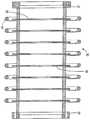
도 1은 자기 타겟 챔버를 갖는 발생기의 제 1 도면;
도 2는 자기 타겟 챔버를 갖는 발생기의 제 2 도면;
도 3은 선형 타겟 챔버를 갖는 발생기의 제 1 도면;
도 4는 이온 소스의 제 1 도면;
도 5는 이온 소스의 단면도;
도 6은 가속기의 제 1 도면;
도 7은 가속기의 단면도;
도 8은 차동 펌핑의 제 1 도면;
도 9는 차동 펌핑의 단면도;
도 10은 가스 여과 시스템의 제 1 도면;
도 11은 자기 타겟 챔버의 제 1 도면;
도 12는 자기 타겟 챔버의 단면도;
도 13은 선형 타겟 챔버의 제 1 도면;
도 14는18F 및13N 생성에 대한 예시적인 동위원소 발생 시스템을 나타내는 선형 타겟 챔버의 단면도;
도 15는 선형 타겟 챔버 및 동기화된 고속 펌프를 갖는 발생기의 제 1 도면;
도 16은 이온 빔의 통과를 허용하는 추출 상태 시 동기화된 고속 펌프의 단면도;
도 17은 이온 빔의 통과를 허용하지 않는 억제 상태 시 동기화된 고속 펌프의 단면도;
도 18은 선형 타겟 챔버 및 동기화된 고속 펌프를 갖는 발생기 및 제어기의 일 실시예의 개략적인 도면;
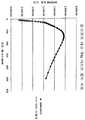
도 19는 10 torr 가스 압력 및 25 ℃에서2H 이온들에 대한3He 가스의 정지 파워(stopping power)에 대한, 정지 파워(keV/㎛) 대 이온 에너지(keV)의 그래프;
도 20은 10 torr 가스 압력 및 25 ℃에서2H 이온들에 대한3He 가스의 정지 파워에 대한, 정지 파워(keV/㎛) 대 이온 에너지(keV)의 그래프;
도 21은 10 torr의3He 타겟에 충돌하는 100 mA 입사2H 빔에 대한, 핵융합 반응 속도(반응/초) 대 이온 빔 입사 에너지(keV)의 그래프;
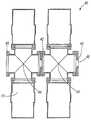
도 22는 의료용 동위원소의 생산에 적합한 핵융합부 및 핵분열부를 포함한 하이브리드 원자로의 사시도;
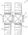
도 23은 의료용 동위원소의 생산에 적합한 핵융합부 및 핵분열부를 포함한 하이브리드 원자로의 또 다른 구성의 사시도;
도 24는 다양한 물질층들을 예시하는 핵분열 원자로의 개략적인 측면도;
도 25는 다양한 물질층들을 예시하는 도 24의 핵분열 원자로의 개략적인 평면도;
도 26은 다양한 물질층들을 예시하는 또 다른 핵분열 원자로의 개략적인 측면도;
도 27은 다양한 물질층들을 예시하는 도 26의 핵분열 원자로의 개략적인 평면도;
도 28은 다양한 물질층들을 예시하고, 특히98Mo로부터99Mo를 형성하는데 적합한 또 다른 핵분열 원자로의 개략적인 측면도; 및
도 29는 다양한 물질층들을 예시하는 도 28의 핵분열 원자로의 개략적인 평면도이다.BRIEF DESCRIPTION OF THE DRAWINGS The invention may be further understood and appreciated by reference to the detailed description of specific embodiments presented hereto in the accompanying drawings, wherein:
BRIEF DESCRIPTION OF THE DRAWINGS Figure 1 is a first view of a generator with a magnetic target chamber;
2 is a second diagram of a generator having a magnetic target chamber;
Figure 3 is a first view of a generator having a linear target chamber;
4 shows a first view of an ion source;
5 is a cross-sectional view of an ion source;
6 is a first view of an accelerator;
7 is a cross-sectional view of the accelerator;
8 is a first diagram of differential pumping;
9 is a cross-sectional view of differential pumping;
10 is a first view of a gas filtration system;
11 is a first view of a magnetic target chamber;
12 is a cross-sectional view of a magnetic target chamber;
13 is a first view of a linear target chamber;
14 is a cross-sectional view of a linear target chamber illustrating an exemplary isotope generation system for18 F and13 N production;
15 is a first view of a generator having a linear target chamber and a synchronized high speed pump;
16 is a cross-sectional view of a synchronized high speed pump in an extraction state that allows passage of an ion beam;
17 is a cross-sectional view of a synchronized high speed pump in an inhibition state that does not allow passage of an ion beam;
18 is a schematic diagram of one embodiment of a generator and controller having a linear target chamber and a synchronized high speed pump;
19 is a graph of quiescent power (keV / 占 퐉) versus ion energy (keV) versus stopping power of3 He gas at 10 torr gas pressure and2 H ions at 25 占 폚;
20 is a graph of quiescent power (keV / 탆) versus ion energy (keV) versus quiescent power of3 He gas at 10 torr gas pressure and2 H ions at 25 캜;
21 is a graph of the fusion reaction rate (reaction / sec) vs. ion beam incident energy (keV) for a 100 mA incident2 H beam impinging on a 10 torr3 He target;
22 is a perspective view of a hybrid reactor including a fusion portion and a fission portion suitable for the production of medical isotopes;
Figure 23 is a perspective view of yet another configuration of a hybrid reactor including a fusion portion and a fission portion suitable for the production of medical isotopes;
24 is a schematic side view of a fission reactor illustrating various layers of material;
Figure 25 is a schematic plan view of the fission reactor of Figure 24 illustrating various layers of material;
Figure 26 is a schematic side view of another fission reactor illustrating various layers of material;
Figure 27 is a schematic plan view of the fission reactor of Figure 26 illustrating various layers of material;
28 illustrates a schematic side view of yet another fission reactor suitable for forming99 Mo from < RTI ID = 0.0 >98 < / RTI>Mo; And
Figure 29 is a schematic plan view of the fission reactor of Figure 28 illustrating various layers of material.
본 발명의 여하한의 실시예들이 상세히 설명되기 전에, 본 발명은 본 명세서에서 아래의 설명들에서 설명되거나 아래의 도면들에 예시되는 구성요소들의 구성 및 배치의 세부내용에 제한되지 않는다는 것을 이해하여야 한다. 본 발명은 다른 실시예들을 수행할 수 있으며, 다양한 방식들로 실시되거나 수행될 수 있다. 또한, 본 명세서에서 사용되는 어법 및 전문용어는 설명을 위한 것이며, 제한하는 것으로서 간주되어서는 안 된다는 것을 이해하여야 한다. 본 명세서에서, "포함하는", "포괄하는", 또는 "갖는"이라는 용어 및 그 변형의 사용은 이후 열거되는 아이템들 및 그 균등물뿐 아니라 추가 아이템들도 포함하는 것으로 생각된다. 달리 명시되거나 제한되지 않는 경우, "장착된", "연결된", "지지된", 및 "커플링된"이라는 용어 및 그 변형은 폭넓게 사용되며, 직접적이고 간접적인 장착, 연결, 지지, 및 커플링을 포함한다. 또한, "연결된" 및 "커플링된"이라는 용어는 물리적이거나 기계적인 연결 또는 커플링에 국한되지 않는다.Before any of the embodiments of the present invention are described in detail, it is to be understood that the present invention is not limited to the details of construction and the arrangement of components described in the following description or illustrated in the drawings below do. The invention may be capable of other embodiments and of being practiced or of being carried out in various ways. It is also to be understood that the phraseology and terminology employed herein is for the purpose of description and should not be regarded as limiting. The use of the terms " comprises, "or" having ", and variations thereof, are contemplated herein as including additional items as well as items enumerated below and equivalents thereof. The terms "attached," " coupled, "" supported," and "coupled, " and variations thereof, are broadly used and include direct and indirect mounting, Ring. Also, the terms "connected" and "coupled" are not limited to physical or mechanical connections or couplings.
적어도 1 이상의 실시예를 설명하기 전에, 본 발명은 본 명세서에서 예시들에 의해 구현되는 바와 같은 아래의 설명에서 설명되는 세부내용에 제한되지 않는다는 것을 이해하여야 한다. 이러한 설명 및 예시들은 첨부된 청구항들에서 설명되는 바와 같은 본 발명의 범위를 제한하는 것으로 의도되지 않는다. 본 발명은 다른 실시예들을 수행할 수 있으며, 다양한 방식들로 실시되거나 수행될 수 있다.Before describing at least one embodiment, it is to be understood that the invention is not limited to the details set forth in the following description, as embodied by the examples herein. These descriptions and examples are not intended to limit the scope of the invention as set forth in the appended claims. The invention may be capable of other embodiments and of being practiced or of being carried out in various ways.
이 기재내용을 전체에 걸쳐, 본 발명의 다양한 실시형태들이 범위 형태로 제시될 수 있다. 범위 형태의 설명은 단지 편의 및 간결성을 위한 것이며, 본 발명의 범위에 대한 불변의 한계로서 해석되어서는 안 된다는 것을 이해하여야 한다. 따라서, 당업자라면 이해하는 바와 같이, 특히 기록된 설명을 제공하는 것에 관하여 여하한의 모든 목적을 위해, 본 명세서에 기재된 모든 범위들은 여하한의 모든 가능한 하위범위 및 하위범위들의 조합들뿐만 아니라, 그 범위 내의 모든 전체 및 부분적인 수치도 포함한다. 단 하나의 예시로서, 20 % 내지 40 %의 범위는 20 % 내지 32.5 %와 32.5 % 내지 40 %, 20 % 내지 27.5 %와 27.5 % 내지 40 % 등의 범위들로 분해될 수 있다. 여하한의 열거된 범위는 동일한 범위를 적어도 2등분, 3등분, 4등분, 5등분, 10등분 등으로 분해할 수 있고, 이를 충분히 설명하는 것으로서 쉽게 인지될 수 있다. 비-제한적인 예시로서, 본 명세서에서 서술되는 각각의 범위는 하위 1/3(lower third), 중간 1/3(middle third), 및 상위 1/3(upper third) 등으로 쉽게 분해될 수 있다. 또한, 당업자라면 이해하는 바와 같이, "까지", "적어도", "보다 많이", "보다 적게", "이상" 등과 같은 모든 언어는 인용된 수를 포함하며, 후속하여 앞서 언급된 바와 같이 하위범위들로 분해될 수 있는 범위들을 칭한다. 동일한 방식으로, 본 명세서에 기재된 모든 비율들도 더 폭넓은 비율 내에 포함되는 모든 하위비율을 포함한다. 이들은 단지 구체적으로 의도되는 것의 예시들이다. 또한, 본 명세서에서 제 1 표시 숫자와 제 2 표시 숫자 "사이의 범위들/범위인", 및 제 1 표시 숫자"로부터" 제 2 표시 숫자"까지의 범위들/범위인"이라는 구는 교환가능하게 사용된다.Throughout this description, various embodiments of the invention may be presented in scoped form. It should be understood that the description of the scope form is merely for convenience and brevity, and should not be construed as a limit on the scope of the invention. Thus, as will be appreciated by those skilled in the art, and for all purposes, particularly with respect to providing a written description, all ranges described herein are intended to encompass all possible combinations of subranges and subranges, It also includes all full and partial values within the range. As one example, the range of 20% to 40% can be broken down into ranges of 20% to 32.5%, 32.5% to 40%, 20% to 27.5%, and 27.5% to 40%. Any of the enumerated ranges can be easily identified as fully explaining and explaining the same range at least in two, three, four, five, ten, and so on. As a non-limiting example, each of the ranges described herein can be easily decomposed into a lower third, a middle third, and an upper third, . It will also be appreciated by those skilled in the art that any language such as "to," " at least, "" more," " less, " Quot; refers to ranges that can be decomposed into ranges. In the same manner, all ratios described herein also include all the lower ratios included in the wider ratios. These are just examples of what is specifically intended. Also, the phrases "range / range between first display number and second display number ", and ranges / range from first display number" to "second display number" Is used.
본 명세서에서, "실질적으로", "약", "대략" 등과 같은 용어들은 디바이스의 성능에 큰 영향을 주지 않고 이상적이거나 설명된 조건으로부터 벗어날 수 있는 특징들 및 특성들을 설명하는데 사용된다. 예를 들어, "실질적으로 평행인"이라는 용어는 바람직하게는 평행하지만, 편차가 디바이스에 큰 악영향을 주지 않는 한 20 도까지 벗어날 수 있는 특징들을 설명하는데 사용될 수 있다. 이와 유사하게, "실질적으로 선형인"이라는 용어는 선형성으로부터의 편차가 디바이스의 성능에 큰 악영향을 주지 않는 한, 약간 구부러진 경로 또는 약간 곡선형인 경로를 포함할 수 있다.In this specification, terms such as " substantially ", "about "," roughly ", and the like are used to describe features and characteristics that are ideal or deviate from the described conditions without significantly affecting the performance of the device. For example, the term "substantially parallel" is preferably parallel but can be used to describe features that can deviate to 20 degrees, unless the deviations have a significant adverse effect on the device. Similarly, the term "substantially linear" may include a slightly curved path or a slightly curved path so long as the deviation from linearity does not adversely affect the performance of the device.
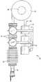
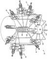
도 22는 의료용 동위원소의 생산에 적합한 하이브리드 원자로(5a)의 일 구성을 예시한다. 설명에 앞서, 본 명세서에서 사용된 "하이브리드 원자로"라는 용어는 핵융합부 및 핵분열부를 포함하는 원자로를 설명하는 것으로 여겨진다. 특히, 예시된 원자로(5a)는 LEU의 용액으로부터 또는98Mo로부터99Mo를 생성하는데 적합하다. 하이브리드 원자로(5a)는 원하는 동위원소를 생산하도록 상호작동하는 핵융합부(10) 및 핵분열부(8)를 포함한다. 도 22에 예시된 구성에서는, 10 개의 별도 핵융합부(10)들이 채택된다. 각각의 핵융합부(10)는 자기 핵융합부(10)로서 배치되며, 도 1 및 도 2에 관하여 설명되는 바와 같은 중성자 소스로서 작용한다. 물론, 다른 구성들이 더 적은 핵융합부(10), 더 많은 핵융합부(10), 또는 필요에 따라 핵융합부들의 다른 구성들을 사용할 수 있다.Figure 22 illustrates one configuration of a
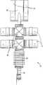
도 23은 의료용 동위원소의 생산에 적합한 하이브리드 원자로(5b)의 또 다른 구성을 예시한다. 도 23의 구성에서는, 선형 핵융합부(11)들이 도 3 및 도 4에 관하여 설명되는 바와 같은 중성자 소스로서 작용한다. 도 23의 구성에서, 선형 핵융합부(11)들은 5 개의 핵융합부(11)가 핵분열부(8)의 일 단부에 위치되고, 5 개의 핵융합부(11)는 핵분열부(8)의 맞은편 단부에 위치되도록 배치된다. 물론, 필요에 따라 다른 수량의 핵융합부(11)들 또는 핵융합부들의 다른 구성들을 채택하는 다른 구성들이 채택될 수도 있다.Figure 23 illustrates another configuration of a hybrid reactor (5b) suitable for the production of medical isotopes. In the configuration of Fig. 23, the
도 1 내지 도 3에 예시된 바와 같이, 각각의 핵융합부(10, 11)는 고에너지 양성자 소스 또는 중성자 소스로서 기능할 수 있는 컴팩트 디바이스(compact device)를 제공한다. 일 실시예에서, 핵융합부들(10, 11)은 양성자들을 발생시키도록2H-3He(듀테륨-헬륨 3) 핵융합 반응들을 이용하며, 이는 이후 다른 동위원소를 발생시키는데 사용될 수 있다. 또 다른 실시예에서, 핵융합부들(10, 11)은 기본 반응들을2H-3H,2H-2H, 또는3H-3H 반응들로 변화시킴으로써 중성자 소스들로서 기능한다.As illustrated in Figures 1 to 3, each
종래 형태의 양성자 또는 중성자 소스들에서의 고유한 단점들을 고려하여, 핵융합부들(10, 11)은 의료용 동위원소의 생산에 이용될 수 있는 신규한 고에너지 양성자 또는 중성자 소스(본 명세서에서, 때로는 일반적으로 이온 소스라 하지만, 더 올바르게는 입자 소스로 간주됨)를 제공한다. 각각의 핵융합부(10, 11)는 핵융합 반응을 야기하기 위해 소량의 에너지를 이용하며, 이는 이후 동위원소 생산에 사용될 수 있는 고에너지 양성자 또는 중성자를 생성한다. 소량의 에너지를 이용하는 것은, 디바이스로 하여금 이전의 종래 디바이스들보다 더 컴팩트하게 할 수 있다.In view of the inherent disadvantages of proton or neutron sources of conventional type, the
각각의 핵융합부(10, 11)는 적절하게는18F,11C,15O,13N,63Zn,124I, 및 많은 다른 것들을 포함하고, 이에 제한되지는 않는 다른 동위원소들을 발생시키는데 사용될 수 있는 양성자들을 발생시킨다. 연료 형태를 변화시킴으로써, 각각의 핵융합부는131I,133Xe,111In,125I,99Mo(이는99mTc로 붕괴함) 및 많은 다른 것들을 포함하고, 이에 제한되지는 않는 동위원소들을 발생시키는데 사용될 수 있는 높은 플럭스의 등방성 중성자들을 발생시키는데 사용될 수도 있다. 이러한 것으로서, 각각의 핵융합부(10, 11)는 이제까지 언급된 양성자 또는 중성자 소스들을 능가하는 많은 장점들을 갖는 의료용 동위원소 발생과 같은 사용을 위한 신규한 컴팩트 고에너지 양성자 또는 중성자 소스를 제공한다.Each fusion portion10,11 may be used to generate other isotopes including, but not limited to,18 F,11 C,15 O,13 N,63 Zn,124 I, Generate proton capable. By varying the fuel type, each fusion unit generates isotopes including, but not limited to,131 I,133 Xe,111 In,125 I,99 Mo (which collapses at99m Tc) May be used to generate high flux of isotropic neutrons that may be used. As such, each
일반적으로, 각각의 핵융합부(10, 11)는 양성자 또는 중성자를 발생시키는 장치를 제공하며, 이는 차례로 다양한 방사성핵종(또는 방사성동위원소)을 발생시키는데 적절히 사용된다. 도 1 및 도 2를 참조하면, 각각의 자기 핵융합부(10)는 적절하게는 RF-구동 이온 발생기 및/또는 안테나(24)를 포함할 수 있는 플라즈마 이온 소스(20), 적절하게는 전극-구동되는 가속기(30), 및 타겟 챔버(60)를 포함한 타겟 시스템을 포함한다. 양성자-기반 방사성동위원소 생산의 경우, 상기 장치는 동위원소 추출 시스템(90)을 포함할 수도 있다. RF-구동 플라즈마 이온 소스(20)는 사전설정된 경로를 따라 지향되는 이온 빔을 발생시키고 시준하며, 상기 이온 소스(20)는 제 1 유체의 유입을 위한 유입구를 포함한다. 전극-구동 가속기(30)는 이온 빔을 수용하고, 이온 빔을 가속시켜 가속화된 이온 빔을 산출한다. 타겟 시스템은 가속화된 이온 빔을 수용한다. 타겟 시스템은 가속화된 빔과 반응하고, 차례로 핵입자들, 즉 양성자 또는 중성자를 방출하는 핵입자-유도, 예를 들어 양성자-유도 또는 중성자 유도 타겟 물질을 포함한다. 방사성동위원소 생산을 위해, 타겟 시스템은 핵입자들에 투명한 측벽들을 가질 수 있다. 타겟 시스템 부근이나 내부에 동위원소 추출 시스템(90)이 배치되며, 이는 방사성핵종(또는 방사성동위원소)을 산출하도록 핵입자들에 반응하는 동위원소-유도 물질을 포함한다.Generally, each
본 명세서에서는 RF-구동 이온 발생기 또는 이온 소스가 설명되지만, 다른 시스템들 및 디바이스들도 원하는 이온들을 발생시키기에 적합하다는 것을 유의하여야 한다. 예를 들어, 다른 구성들은 RF-구동 이온 발생기 또는 이온 소스 대신에, 또는 이와 함께 DC 아크 소스(arc source)를 채택할 수 있다. 또 다른 구성들은 DC 아크 소스 및/또는 RF-구동 이온 발생기 또는 이온 소스 대신에, 또는 이와 함께 열음극 이온 소스, 냉음극 이온 소스, 레이저 이온 소스, 전계 방출 소스, 및/또는 전계 증발 소스(field evaporation source)를 사용할 수 있다. 이러한 것으로서, 본 발명은 RF-구동 이온 발생기 또는 이온 소스를 채택하는 구성들에 제한되어서는 안 된다.Although an RF-driven ion generator or ion source is described herein, it should be noted that other systems and devices are also suitable for generating the desired ions. For example, other configurations may employ a DC arc source instead of, or in addition to, an RF-driven ion generator or ion source. Other arrangements may include a cold cathode ion source, a cold cathode ion source, a laser ion source, a field emission source, and / or a field evaporation source instead of, or in addition to, a DC arc source and / source can be used. As such, the invention should not be limited to configurations employing RF-driven ion generators or ion sources.
설명된 바와 같이, 핵융합부는 자기 구성(10) 및/또는 선형 구성(11)으로 배치될 수 있다. 디바이스의 6 개의 주요 부분들 또는 구성요소들이 도 1 및 도 2에 자기 구성(10)에 대해, 또한 도 3에 선형 구성(11)에 대해 나타낸 바와 같이 연결된다. 각각의 핵융합부는 자기 구성으로 배치되든지 선형 구성으로 배치되든지 상관없이, 일반적으로 20으로 표시된 이온 소스, 가속기(30), 차동 펌핑 시스템(40), 자기 구성(10)에 대한 타겟 챔버(60) 또는 선형 구성(11)에 대한 타겟 챔버(70)를 포함하는 타겟 시스템, 일반적으로 80으로 표시된 이온 한정 시스템, 및 일반적으로 90으로 표시된 동위원소 추출 시스템을 포함한다. 각각의 핵융합부는 추가적으로 가스 여과 시스템(50)을 포함할 수 있다. 또한, 각각의 핵융합부는 차동 펌핑 시스템(40) 대신에, 또는 이에 추가하여 동기화된 고속 펌프(100)를 포함할 수 있다. 펌프(100)는 특히 타겟 챔버의 선형 구성과 작동한다.As described, the fusion portion can be arranged in a
이온 소스(20)(도 4 및 도 5)는 진공 챔버(25), 무선주파수(RF) 안테나(24), 및 이온 주입기 최초 스테이지(first stage: 23) 및 이온 주입기 최종 스테이지(35)(도 6)를 갖는 이온 주입기(26)를 포함한다. 더 많은 이온 전류를 산출하기 위해, 이온 소스로 하여금 더 높은 밀도의 플라즈마(22)를 생성하는 고밀도 헬리콘(helicon) 모드에서 작동하게 하도록 자석(도시되지 않음)이 포함될 수 있다. 적절하게는, 이 자석의 필드 강도는 약 50 G 내지 약 6000 G, 적절하게는 약 100 G 내지 약 5000 G의 범위이다. 자석들은 축방향 필드(이온 빔의 경로에 평행한 남북 방위) 또는 커스프 필드(cusp field)(인접한 자석들에 대해 남과 북 사이에서 교번하는 내부 극을 이용하여 이온 빔의 경로에 수직인 남북 방위)를 생성하도록 방위될 수 있다. 축방향 필드는 헬리콘 모드(조밀한 플라즈마)를 생성할 수 있는 반면, 커스프 필드는 헬리콘 유도 모드가 아닌 조밀한 플라즈마를 발생시킬 수 있다. 진공 챔버(25)의 일 단부에 가스 유입구(21)가 위치되고, 이 반대편에 이온 주입기(26)의 최초 스테이지(23)가 있다. 가스 유입구(21)는 원하는 연료 형태들 중 하나를 제공하며, 이는1H2,2H2,3H2,3He, 및11B를 포함하거나,1H,2H,3H,3He, 및11B를 포함할 수 있다. 유입구(21)에서의 가스 흐름은 적절하게는 질량 흐름 제어기(도시되지 않음)에 의해 조절되며, 이는 사용자에 의하거나 자동으로 제어될 수 있다. RF 안테나(24)는 적절하게는 진공 챔버(25)의 외부 주위에 감긴다. 대안적으로, RF 안테나(24)는 진공 챔버(25) 내부에 있을 수 있다. 적절하게는, RF 안테나(24)에 의해 방출된 무선주파수 방사선(radio frequency radiation)이 예를 들어 플라즈마를 형성하는 진공 챔버(25)의 내용물(즉, 연료 가스)을 여기시키도록, RF 안테나(24)는 진공 챔버에 가깝다. RF 안테나(24)는 1 이상의 턴(turn)의 튜브(27)를 포함한다. RF 튜브 또는 와이어(27)는 구리, 알루미늄, 또는 스테인리스 강과 같은 전도성이고 구부릴 수 있는 재료로 구성될 수 있다.The ion source 20 (Figures 4 and 5) includes a
이온 주입기(26)는 1 이상 형성된 스테이지들(23 및 35)을 포함한다. 이온 주입기의 각 스테이지는, 적절하게는 이온 빔의 효과적인 시준을 제공하도록 합금 또는 금속을 포함할 수 있는 전도성 재료로 이루어진 가속 전극(32)을 포함한다. 예를 들어, 전극들은 적절하게는 낮은 스퍼터링 계수(sputtering coefficient)를 갖는 전도성 금속, 예를 들어 텅스텐으로 만들어진다. 다른 적절한 재료들은 알루미늄, 강철, 스테인리스 강, 그래파이트, 몰리브덴, 탄탈룸 등을 포함할 수 있다. RF 안테나(24)는 일 단부에서 RF 임피던스 매칭 회로(도시되지 않음)의 출력에, 또한 다른 단부에서는 접지에 연결된다. RF 임피던스 매칭 회로는 발생기에 의해 필요한 임피던스를 매칭하고 RF 공진을 확립하도록 안테나를 조정할 수 있다. RF 안테나(24)는 적절하게는 폭넓은 범위의 RF 주파수를 발생시키며, 이는 0 Hz 내지 수 kHz, 수 MHz, GHz 이상을 포함하고, 이에 제한되지는 않는다. RF 안테나(24)는 외부 워터쿨러(water cooler: 도시되지 않음)에 의해 물로 냉각되어, 저항의 최소 변화로 높은 파워 손실을 용인할 수 있다. RF 안테나(24)의 턴의 매칭 회로는 RF 파워 발생기(도시되지 않음)에 연결될 수 있다. 이온 소스(20), 매칭 회로, 및 RF 파워 발생기는 최고 가속기 전위에, 또는 약간 더 높이 부유할 수 있으며(접지로부터 절연됨), 이 전위는 고전압 전력 공급기에 전기 연결하여 얻어질 수 있다. RF 파워 발생기는 원격으로 조정가능할 수 있으므로, 빔 세기가 사용자에 의해, 또는 대안적으로 컴퓨터 시스템에 의해 제어될 수 있다. 진공 챔버(25)에 연결된 RF 안테나(24)는 적절하게는 연료를 양이온화하여, 이온 빔을 생성한다. 이온들을 생성하는 대안적인 수단은 당업자에게 알려져 있으며, 마이크로파 방전, 전자-충돌 이온화, 및 레이저 이온화를 포함할 수 있다.The
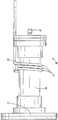
가속기(30)(도 6 및 도 7)는 적절하게는 일 단부에서 이온 소스 정합 플랜지(ion source mating flange: 31)를 통해 이온 소스(20)에 연결되고, 다른 단부에서 차동 펌핑 정합 플랜지(33)를 통해 차동 펌핑 시스템(40)에 연결된 진공 챔버(36)를 포함한다. 또한, 가속기의 최초 스테이지는 이온 주입기(26)의 최종 스테이지(35)이다. 가속기 진공 챔버(36)의 축선을 따라 적어도 1 이상, 적절하게는 3 내지 50, 더 적절하게는 3 내지 20 개의 원형 가속 전극(32)이 배치될 수 있으며, 이는 진공 경계가 유지되게 하면서 가속기 진공 챔버(36)를 관통한다. 가속 전극들(32)은 그 중심을 통하는 홀들[가속기 챔버의 구멍(bore)보다 더 작음]을 가지며, 적절하게는 각각 이온 빔의 경로에 대한 가속기 진공 챔버의 종축(이온 소스 단부로부터 차동 펌핑 단부까지)을 중심으로 한다(center). 가속 전극(32) 내 홀의 최소 직경은 이온 빔의 강도에 따라, 또는 다수 이온 빔들에 따라 증가하며, 약 1 mm 내지 약 20 cm 직경, 및 적절하게는 약 1 mm 내지 약 6 cm 직경의 범위일 수 있다. 진공 챔버(36) 외부에서, 가속 전극들(32)은 전기장을 감소시키고 코로나 방전(corona discharge)을 최소화하는 코로나-방지 링(anti-corona ring: 34)들에 연결될 수 있다. 이 링들은 SF6과 같은 절연용 유전성 가스 또는 유전성 오일 내에 침지될 수 있다. 적절하게는, 차동 펌핑 부분(40)의 연결을 용이하게 하는 차동 펌핑 정합 플랜지(33)가 가속기의 출구에 있다.The accelerator 30 (FIGS. 6 and 7) is suitably connected to the
가속기(30)의 각각의 가속 전극(32)은 고전압 전력 공급기(도시되지 않음)로부터, 또는 당업자에게 알려져 있는 저항 분배기 네트워크(resistive divider network: 도시되지 않음)으로부터 편향되어 공급될 수 있다. 대부분 경우에 대해 상기 분배기가 간단하기 때문에 가장 적절한 구성일 수 있다. 저항 분배기 네트워크를 이용한 구성에서, 가속기의 이온 소스 단부는 고전압 전력 공급기에 연결될 수 있고, 마지막 가속 전극(32)에 대해 두번째는 접지에 연결될 수 있다. 가속 전극들(32)의 중간 전압들은 저항 분배기에 의해 설정될 수 있다. 가속기의 최종 스테이지는, 적절하게는 타겟 챔버로부터의 전자들이 가속기(30)로 역류하는 것을 방지하기 위해 마지막 가속 전극을 통해 음으로 편향된다(biased negatively).Each accelerating electrode 32 of the
대안적인 실시예에서, 앞서 설명된 가속기(30) 대신에 선형가속기(예를 들어, RF 쿼드러폴)가 사용될 수 있다. 선형가속기는 감소된 효율성을 가질 수 있으며, 앞서 설명된 가속기(30)에 비해 크기가 더 크다. 선형가속기는 최초 단부에서 이온 소스(20)에 연결되고, 다른 단부에서 차동 펌핑 시스템(40)에 연결될 수 있다. 선형가속기는 높은 입자 에너지를 얻기 위해 고전압 및 직류 대신에 RF를 사용할 수 있으며, 이들은 당업계에 알려진 바와 같이 구성될 수 있다.In an alternative embodiment, a linear accelerator (e.g., RF quadrupole) may be used instead of the
차동 펌핑 시스템(40)(도 8 및 도 9)은, 적절하게는 차동 펌핑 시스템(40)을 적어도 1 이상의 스테이지로 분리하는 감압 장벽(pressure reducing barrier: 42)을 포함한다. 감압 장벽(42)들은 적절하게는 각각 얇은 고체판 또는 1 이상의 길고 좁은 튜브들을 포함하며, 상기 튜브들은 전형적으로 중심에 작은 홀과 함께 1 cm 내지 10 cm의 직경, 적절하게는 약 0.1 mm 내지 약 10 cm의 직경, 및 더 적절하게는 약 1 mm 내지 약 6 cm의 직경을 갖는다. 각각의 스테이지는 진공 챔버(44), 연계된 감압 장벽들(42), 및 각각 진공 펌프 배출구(41)를 갖는 진공 펌프들(17)을 포함한다. 각각의 진공 챔버(44)는 3, 4, 5, 또는 6 포트 진공 챔버(44)인지에 따라 1 이상, 적절하게는 1 내지 4 개의 진공 펌프들(17)을 가질 수 있다. 진공 챔버(44)의 포트들 중 2 개는 적절하게는 빔라인(beamline) 상에 방위되고, 차동 펌핑 시스템(40)으로부터의 이온 빔 입구 및 출구에 사용된다. 또한, 각각의 진공 챔버(44)의 포트들은 감압 장벽들(42)과 동일한 위치에 있을 수 있다. 각각의 진공 챔버(44)의 남은 포트들은 적절하게는 콘플랫 플랜지(conflat flange)들에 의해 진공 펌프들(17)에 연결되며, 또는 다양한 기기 또는 제어 디바이스들에 연결될 수 있다. 진공 펌프들(17)로부터의 배출 가스는 진공 펌프 배출구(41)를 통해 추가 진공 펌프 또는 필요에 따라 압축기(도시되지 않음)로 공급되고, 가스 여과 시스템(50)으로 공급된다. 대안적으로, 필요에 따라 이 추가 진공 펌프는 가스 여과 시스템(50)과 타겟 챔버(60 또는 70) 사이에 위치될 수 있다. 추가 압축 단계가 존재하는 경우, 이는 진공 펌프들(17)과 여과 시스템(50) 사이에 있을 수 있다. 차동 펌핑 부분은 일 단부에서 가속기 정합 플랜지(45)를 통해 가속기(30)에 연결되고, 다른 단부의 빔 출구 포트(46)에서 타겟 챔버 정합 플랜지(43)를 통해 타겟 챔버(60 또는 70)에 연결된다. 또한, 차동 펌핑 시스템(40)은 층류(laminar flow)를 방해하기 위해 난류 발생 장치(turbulence generating apparatus: 도시되지 않음)를 포함할 수 있다. 난류 발생 장치는 유체의 흐름을 제한할 수 있으며, 층류를 방해하기 위해 표면 범프(surface bump) 또는 다른 피처들 또는 그 조합을 포함할 수 있다. 난류는 전형적으로 층류보다 느리므로, 타겟 챔버로부터 차동 펌핑 부분으로의 유체 누출율을 감소시킬 수 있다.The differential pumping system 40 (FIGS. 8 and 9) suitably includes a
몇몇 구성에서, 감압 장벽(42)들은 플라즈마 윈도우들로 대체되거나, 이에 의해 강화된다. 플라즈마 윈도우들은 감압 장벽들로서 사용된 것과 유사한 작은 홀을 포함한다. 하지만, 홀에 걸쳐 조밀한 플라즈마가 형성되어, 작은 홀을 통하는 가스의 흐름은 막으면서, 이온 빔은 여전히 통과하게 한다. 플라즈마를 제 자리에 유지하도록 홀 내에, 또는 그 부근에 자기장 또는 전기장이 형성된다.In some configurations, the pressure-reducing
가스 여과 시스템(50)은 적절하게는 그 진공 펌프 격리 밸브들(51)에서 차동 펌핑 시스템(40)의 진공 펌프 배출구들(41) 또는 추가 압축기들(도시되지 않음)에 연결된다. 가스 여과 시스템(50)(도 10)은, 진공 펌프 배출 가스(41)가 흐르는 1 이상의 압력 챔버들 또는 "트랩들"(13 및 15)을 포함한다. 트랩들은 적절하게는 타겟 챔버 또는 이온 소스를 빠져나갈 수 있는 유체 불순물들을 포획하며, 이는 예를 들어 대기로부터 시스템으로 새어 들어갔을 수 있다. 트랩들은 액체 질소를 이용하여 극저온으로 냉각될 수 있다(LN 트랩들: 15). 이러한 것으로서, 콜드 액체 트랩(cold liquid trap: 13 및 15)은 적절하게는 대기 오염물과 같은 가스를 액화하고 트랩들(13 및 15) 내에 남게 한다. 직렬로 연결된 1 이상의 LN 트랩들(15)에 걸쳐 흐른 이후, 가스는 적절하게는 티타늄 게터 트랩(titanium getter trap: 13)으로 보내지며, 이는 타겟 챔버 또는 이온 소스를 빠져나갈 수 있고, 아니면 타겟 챔버를 오염시킬 수 있는 듀테륨과 같은 오염 수소 가스들을 흡수한다. 게터 트랩(13)의 유출구는 적절하게는 가스 여과 시스템(50)의 타겟 챔버 격리 밸브(52)를 통해 타겟 챔버(60 또는 70)에 연결된다. 가스가 시스템으로 일정하게 흐르고, 진공 펌프 배출구(41)로부터 다른 진공 펌프 배출구(도시되지 않음) 및 시스템 외부로 배출되기 원하는 경우, 가스 여과 시스템(50)이 디바이스(10)로부터 완전히 제거될 수 있다. 가스 여과 시스템(50) 없이도, 장치(10)의 작동은 실질적으로 변경되지 않을 것이다. 중성자 소스로서 기능하는 장치(10)는 가스 여과 시스템(50)의 게터 트랩(13)을 포함하지 않을 수 있다.The
진공 펌프 격리 밸브들(51) 및 타겟 챔버 격리 밸브들(52)은, 트랩들이 가스로 포화되는 경우, 가스 여과 시스템(50)이 나머지 디바이스로부터 격리되고 펌프아웃 밸브(pump-out valve: 53)를 통해 외부 펌프(도시되지 않음)에 연결되기 쉽게 할 수 있다. 이러한 것으로서, 진공 펌프 격리 밸브들(51) 및 타겟 챔버 격리 밸브들(52)은 폐쇄되고, 펌프아웃 밸브들(53)이 불순물들을 퍼내도록 개방될 수 있다.Vacuum
타겟 챔버 60[도 11 및 도 12, 자기 시스템(10)용] 또는 타겟 챔버 70[도 13 및 도 14, 선형 시스템(11)용]은 약 0 내지 약 100 torr, 약 100 mtorr 내지 약 30 torr, 적절하게는 약 0.1 내지 약 10 torr, 적절하게는 약 100 mtorr 내지 약 30 torr의 압력의 타겟 가스로 채워질 수 있다. 타겟 챔버(60 또는 70)의 특정 지오메트리는 주요 적용에 따라 변할 수 있으며, 많은 변형을 포함할 수 있다. 타겟 챔버는 적절하게는 선형 시스템(14)에 대해 약 10 cm 내지 약 5 m 길이, 및 약 5 mm 내지 약 100 cm 직경의 원통형일 수 있다. 하이브리드 원자로에서 사용되는 경우, 타겟 챔버는 그 중심에 활성화 칼럼(activation column)을 제공하도록 배치된다. 핵융합부들은 활성화 칼럼 외부의 타겟 챔버를 통해 빔들을 지향하도록 배치된다. 따라서, 빔들은 실질적으로 환형 공간 내에서 이동한다. 적절하게는, 타겟 챔버(70)는 선형 시스템(14)에 대해 약 0.1 m 내지 약 2 m 길이, 및 약 30 내지 50 cm 직경일 수 있다.The target chamber 60 (FIGS. 11 and 12, for the magnetic system 10) or the target chamber 70 (for the
자기 시스템(12)에 대해, 타겟 챔버(60)는 약 10 cm 내지 약 1 m 높이, 및 약 10 cm 내지 약 10 m 직경의 두꺼운 팬케이크를 닮을 수 있다. 적절하게는, 자기 시스템(12)에 대한 타겟 챔버(60)는 약 20 cm 내지 약 50 cm 높이, 및 거의 50 cm 직경일 수 있다. 자기 타겟 챔버(60)에 대해, 타겟 챔버의 외경 주위 또는 진공 벽들의 외부의 팬케이크의 면들에 한 쌍의 영구 자석들 또는 전자석들[이온 한정 자석(12)]이 위치될 수 있다(도 11 및 도 12 참조). 자석들은 적절하게는 구리와 알루미늄 또는 초전도체, 또는 전자석들에 대해서는 NdFeB를 포함한 재료들로 구성되고, 이에 제한되지는 않는다. 자석들의 극들은, 이들이 타겟 챔버의 벌크 부피(bulk volume) 내에 축방향 자기장을 생성하도록 방위될 수 있다. 자기장은 적절하게는 1010 강철과 같은 고 도자성 자기 재료들, 뮤우메탈(mu-metal), 또는 다른 재료들을 포함한 자기 회로로 제어된다. 자기 타겟 챔버의 크기 및 자기 빔 에너지가 수학식 (1)에 따라 필드 강도를 결정한다:For

중양성자들에 대해, r은 미터 단위이며, E는 eV 단위의 빔 에너지이고, B는 가우스 단위의 자기장 강도이다. 자석들은 팬케이크의 평탄한 면들에 평행하게 방위되고, 가속기(30)로부터의 빔의 방향에 수직인 자기장이 존재하도록 분극될 수 있으며, 즉 자석들은 이온 재순환을 야기하도록 챔버의 최상부 및 저부에 장착될 수 있다. 자기 타겟 챔버(60)를 이용하는 또 다른 실시예에서, 적절하게는 자기 타겟 챔버의 어느 한 단부(최상부 및 저부)에 미러자기장(mirror field)을 생성하도록 타겟 챔버의 최상부 및 저부에 추가 자석들이 존재하며, 이는 타겟 챔버의 양 단부들에 더 강한 자기장의 국부화된 구역들을 생성하여, 이온 빔이 타겟 챔버의 단부들로부터 반사되게 하는 거울 효과를 생성한다. 미러자기장을 생성하는 이 추가 자석들은 영구 자석들 또는 전자석들일 수 있다. 또한, 유사한 거울 효과를 생성하도록 타겟 챔버의 반경방향 에지 부근에 더 강한 자기장을 제공하는 것이 바람직하다. 다시, 원하는 강한 자기장을 제공하도록 형성된 자기 회로 또는 추가 자석들이 사용될 수 있다. 타겟 챔버의 일 단부는 차동 펌핑 정합 플랜지(33)를 통해 차동 펌핑 시스템(40)에 연결되어 작동하며, 가스 재순환 포트(62)가 가스로 하여금 가스 여과 시스템(50)으로부터 타겟 챔버로 다시 들어가게 한다. 또한, 타겟 챔버는 다양한 동위원소 발생 장치가 연결되게 하는 피드스루 포트(feedthrough port: 도시되지 않음)들을 포함할 수 있다.For neutrons, r is in meters, E is the beam energy in eV, and B is the magnetic field strength in gauss. The magnets may be oriented parallel to the flat sides of the pancake and polarized so that there is a magnetic field perpendicular to the direction of the beam from the
타겟 챔버(60)의 자기 구성에서, 자기장은 이온들을 타겟 챔버 내에 한정시킨다. 타겟 챔버(70)의 선형 구성에서는, 타겟 가스에 의해 주입된 이온들이 한정된다. 양성자 또는 중성자 소스로서 사용되는 경우, 타겟 챔버는 방사선으로부터 디바이스의 조작자를 보호하는 차폐를 필요로 할 수 있으며, 차폐는 적절하게는 적어도 1 피트 이상인 두께의 콘크리트 벽들에 의해 제공될 수 있다. 대안적으로, 디바이스는 사용자들로부터 떨어진 지하 또는 벙커에 저장될 수 있으며, 물 또는 다른 유체, 또는 그 조합들이 차폐물로서 사용될 수 있다.In the magnetic configuration of the
차동 펌핑 시스템(40) 및 가스 여과 시스템(50)은 모두 타겟 챔버(60 또는 70)로 공급할 수 있다. 차동 펌핑 시스템(40)은 적절하게는 이온 빔을 제공하는 한편, 가스 여과 시스템(50)은 타겟 챔버를 채우도록 여과된 가스의 흐름을 공급한다. 대안적으로, 동위원소 발생의 경우에 동위원소 추출 시스템(90)으로 하여금 외부에 연결되게 하도록 타겟 챔버(60 또는 70)에 진공 피드스루(도시되지 않음)가 장착될 수 있다.The
동위원소 발생 시스템(63)을 포함한 동위원소 추출 시스템(90)은 모 화합물 또는 물질을 제공하고, 타겟 챔버 내부 또는 부근에 발생된 동위원소들을 제거하는 여하한 수의 구성들일 수 있다. 예를 들어, 동위원소 발생 시스템(63)은 활성화 튜브(activation tube: 64)(도 12 및 도 14)를 포함할 수 있으며, 이는 원통형 타겟 챔버 내부에 꼭 맞는 팽팽하게 감긴 나선부이고, 벽들(65)을 갖는다. 대안적으로, 이온 한정 시스템(80)을 갖는 팬케이크 타겟 챔버의 경우, 이는 모두 직렬로 연결된 팬케이크의 최상면 및 저면 상의 2 개의 나선 및 팬케이크의 원주를 따라 디바이스를 덮는 나선부를 포함할 수 있다. 이 구성들에서 사용되는 활성화 튜브(64)의 벽들(65)은 균열을 견디도록 충분히 강하며, 14 MeV(대략 10 내지 20 MeV)를 넘는 양성자들이 이들을 통과할 수 있는 한편 그 에너지 대부분은 여전히 유지하도록 충분히 얇다. 재료에 따라, 배관(tubing)의 벽들은 약 0.01 mm 내지 약 1 mm 두께, 및 적절하게는 약 0.1 mm 두께일 수 있다. 배관의 벽들은 적절하게는 중성자들을 발생시키지 않을 재료들로 구성된다. 얇은 벽으로 둘러싸인(thin-walled) 배관은 알루미늄, 탄소, 구리, 티타늄 또는 스테인리스 강과 같은 재료들로 만들어질 수 있다. 피드스루(도시되지 않음)는 활성화 튜브(64)를 시스템의 외부에 연결할 수 있으며, 이때 파생 또는 생성 화합물이 풍부한 유체가 냉각을 위한 열 교환기(도시되지 않음), 및 모 화합물, 파생 화합물, 및 불순물의 혼합물로부터 파생 또는 생성 동위원소 화합물들이 분리되는 화학 분리기(도시되지 않음)에 이를 수 있다.The
도 15에 나타낸 또 다른 구성에서, 가속기(30)와 타겟 챔버(60 또는 70) 사이에 고속 펌프(100)가 위치된다. 고속 펌프(100)는 차동 펌핑 시스템(40) 및/또는 가스 여과 시스템(50)을 대체할 수 있다. 고속 펌프는 적절하게는 1 이상의 블레이드들이나 회전자들(102), 및 제어기(108)에 연결되어 작동하는 타이밍 신호(104)를 포함한다. 고속 펌프는 가속기 부분으로부터의 이온 빔 흐름과 동기화되어, 이온 빔과 갭들(106)이 정렬되는 경우에 이온 빔 또는 빔들이 블레이드들(102) 사이 또는 그 안의 적어도 1 이상의 갭(106)을 통과하게 할 수 있다. 타이밍 신호(104)는 블레이드들 중 적어도 1 이상에, 또는 펌프 샤프트를 따라 1 이상의 마커를 가짐으로써 생성될 수 있다. 마커들은 광학적이거나 자기적이며, 또는 당업계에 알려져 있는 다른 적절한 마커들일 수 있다. 타이밍 신호(104)는 블레이드들(102) 또는 갭(106)의 위치, 및 가속기(30)의 최초 스테이지(35)로부터 고속 펌프(100)를 통해 타겟 챔버(60 또는 70)까지 이온 빔의 통과를 허용하기 위한 이온 빔과 정렬된 갭의 존재 여부를 나타낼 수 있다. 타이밍 신호(104)는, 이온 빔으로 하여금 이온 소스(20) 및 가속기(30)를 나가고 고속 펌프(100)에 들어오게 하는 이온 빔 추출 전압에 대한 게이트 펄스 스위치로서 사용될 수 있다. 시스템을 통해 이온 소스(20)로부터 가속기(30)로, 고속 펌프(100)로, 또한 타겟 챔버(60 또는 70)로 흐르는 경우, 상기 빔은 이온 빔 및 갭(106)이 정렬되는 시간 주기 동안 유지될 수 있고, 그 후 이온 빔 및 갭(106)이 정렬되지 않기 전에, 또한 그동안 멈출 수 있다. 타이밍 신호(104) 및 이온 빔의 조화(coordination)는 제어기(108)에 의해 짜여질 수 있다. 제어기(108)의 일 실시예에서(도 18), 제어기(108)는 억제 전압(이온 빔 오프; 차이는 5 내지 10 kV일 수 있음)과 추출 전압(이온 빔 온; 차이는 20 kV일 수 있음) 사이에서 가속기(30)의 전압을 제어하기 위해, 펄스 처리 유닛(110), 고전압 격리 유닛(112), 및 고속 스위치(114)를 포함할 수 있다. 타이밍 신호(104)는 적절하게는 지연, 또는 다른 로직, 또는 당업계에 알려진 적절한 수단을 통과하는 로직 펄스를 생성한다. 펄스 처리 유닛(110)은 지연을 수용하는 고속 펌프의 터빈을 변경시킬 수 있으며, 고속 스위치(114)는 MOSFET 스위치 또는 당업계에 알려진 다른 적절한 스위치 기술일 수 있다. 고전압 격리 유닛(112)은 광섬유 연결부 또는 당업계에 알려진 다른 적절한 연결부일 수 있다. 예를 들어, 타이밍 신호(104)는 블레이드(102)의 회전당 한번만 갭(106)의 존재 또는 부재를 나타낼 수 있으며, 신호 펄스는 블레이드 선회(revolution)당 n 개의 펄스의 세트를 발생시키도록 제어기(108)를 통해 전자기기의 세트에 신호를 보낼 수 있으며, 이때 한 번의 블레이드 회전에 n 개의 갭이 존재한다. 대안적으로, 타이밍 신호(104)는 블레이드 회전 시 m 개의 갭 각각에 대해 갭(106)의 존재 또는 부재를 나타낼 수 있으며, m 개의 펄스가 각각 블레이드 선회당 하나의 펄스를 발생시키도록 제어기(108)를 통해 전자기기의 세트에 신호를 보낼 수 있고, 이때 한 번의 블레이드 회전에 m 개의 갭이 존재한다. 로직 펄스들은 제어기(108)를 통해 가속기 부분의 최초 스테이지(35)(이온 추출기)로 보내지거나 조화되어, 로직 펄스가 억제 상태로부터 추출 상태로, 또는 그 역으로 변화하도록 가속기 부분의 최초 스테이지(35)를 트리거(trigger)하게 할 수 있다. 가속기가 +300 kV이었다면, 예를 들어 고속 펌프(100) 내에 갭(106)이 존재하지 않는 경우 가속기의 최초 스테이지(35)는 +295 kV로 편향될 수 있으므로, 양이온 빔이 +295 kV로부터 +300kV로 흐르지 않을 것이며, 고속 펌프(100) 내에 갭(106)이 존재하는 경우 가속기의 최초 스테이지(35)는 +310 kV로 편향될 수 있으므로, 이온 빔이 가속기(30)를 통해, 또한 고속 펌프(100) 내의 갭들(106)을 통해 타겟 챔버(60 또는 70)로 이동한다. 억제 상태와 추출 상태 사이의 전압 차는 약 1 kV 내지 약 50 kV, 적절하게는 약 10 kV 내지 약 20 kV와 같은 비교적 작은 변화일 수 있다. 전압의 작은 변화는 억제 상태(도 17)와 추출 상태(도 16) 간의 빠른 변화를 용이하게 할 수 있다. 타이밍 신호(104) 및 제어기(108)는 당업계에 알려진 여하한의 적절한 수단에 의해 작동할 수 있으며, 이는 반도체 및 광섬유를 포함하고 이에 제한되지는 않는다. 이온 빔이 온 및 오프인 시간의 주기는 블레이드들(102)의 회전 속도, 블레이드들 또는 갭들(106)의 수, 및 블레이드들 또는 갭들의 치수들과 같은 인자들에 의존할 수 있다.15, a high-
PET 스캔들에서 이용되는 동위원소들18F 및13N은, 도 12 및 도 14에 예시된 구성부를 이용하여 각각의 핵융합부 내부의 핵반응으로부터 발생될 수 있다. 이 동위원소들은 양성자 충격에 의해 이들의 모 동위원소들, (18F에 대해)18O 및 (13N에 대해)16O로부터 생성될 수 있다. 모의 소스는 물(H218O 또는 H216O)과 같은 유체일 수 있으며, 이는 외부 펌핑 시스템(도시되지 않음)을 통하여 동위원소 발생 시스템을 통해 흐르고, 원하는 파생 화합물을 생성하도록 타겟 챔버에서 고에너지 양성자들과 반응할 수 있다.18F 또는13N의 생성을 위해, 동위원소 발생 시스템(63)을 통해 물(각각 H218O 또는 H216O)이 흐르며, 앞서 언급된 핵융합 반응으로부터 생성된 고에너지 양성자들이 튜브(64) 벽들을 관통하고 모 화합물에 충돌하여18F 또는13N을 생성하는 (p,α) 반응들을 야기할 수 있다. 폐쇄 시스템에서는, 예를 들어 동위원소가 풍부한 물이 유체를 냉각하도록 열 교환기(도시되지 않음)를 통한 후, 유체로부터 동위원소를 분리하기 위해 이온 교환 수지와 같은 화학 필터(도시되지 않음)로 순환될 수 있다. 그 후, 물 혼합물은 타겟 챔버(60 또는 70)로 재순환할 수 있는 한편, 동위원소들은 이미징 또는 다른 절차들을 위해 충분히 생성되었을 때까지 필터, 시린지(syringe) 내에, 또는 당업계에 알려진 다른 적절한 수단에 의해 저장된다.The isotopes18 F and13 N used in the PET scans can be generated from nuclear reactions within each fusion unit using the components illustrated in Figures 12 and 14. These isotopes can be generated from protons by their proton impulses,18 O (for18 F) and16 O (for13 N). The simulated source may be a fluid such as water (H218 O or H216 O), which flows through the isotope generating system through an external pumping system (not shown) and is supplied to the target chamber It can react with high energy proton. (Respectively H218 O or H216 O) flows through the
튜브형 나선이 설명되었지만, 동일하거나 다른 방사성핵종을 생성하는데 사용될 수 있는 많은 다른 지오메트리가 존재한다. 예를 들어, 동위원소 발생 시스템(63)은 적절하게는 평행한 루프들 또는 리브(rib)들을 갖는 평탄한 패널(flat panel)일 수 있다. 또 다른 실시예에서, 진공 챔버 벽에 워터 재킷(water jacket)이 부착될 수 있다.18F 또는13N 생성에 대해, 나선은 여하한 수의 얇은 윈도우들을 포함한 얇은 벽으로 둘러싸인 지오메트리로 대체될 수 있거나, 높은 산소 농도를 포함하는 고체 물질로 대체될 수 있으며, 변환 후 제거되고 처리될 것이다. 다른 수단에 의해 다른 동위원소들이 발생될 수 있다.Although tubular spirals have been described, there are many other geometries that can be used to generate the same or different radionuclides. For example, the
이제, 도 1 및 도 3을 참조하여 핵융합부들의 작동을 설명할 것이다. 핵융합부들 중 하나의 작동 전에, 적절하게는 우선 파워 오프인 이온 소스(20)를 통해3He와 같은 타겟 가스를 미리 흘림으로써 각각의 타겟 챔버(60 또는 70)가 채워진 후, 가스로 하여금 장치(10)를 통해, 또한 타겟 챔버 내로 흐르게 한다. 작동 시,2H2와 같은 반응 가스가 이온 소스(20)에 들어가고, 플라즈마(22)를 형성하도록 RF 필드에 의해 양이온화된다. 진공 챔버(25) 내부의 플라즈마(22)가 이온 주입기(26)를 향해 팽창함에 따라, 플라즈마(22)가 가속기(30) 내에서 더 음인 전위에 의해 영향을 받기 시작한다. 이는 양으로 대전된 이온들을 타겟 챔버(60 또는 70)를 향하여 가속하게 한다. 이온 소스(20) 내의 스테이지들(23 및 35)의 가속 전극들(32)은 이온 빔 또는 빔들을 시준하여, 각각 가속기(30)의 최초 스테이지를 가로질러 거의 균일한 이온 빔 프로파일을 제공한다. 대안적으로, 가속기(30)의 최초 스테이지는 앞서 설명된 바와 같이 이온 빔의 펄스 발생 또는 스위치 온/오프를 가능하게 할 수 있다. 상기 빔이 계속하여 가속기(30)를 통해 이동함에 따라, 각 스테이지에서 추가 에너지를 얻어서, 가속기(30)의 최종 스테이지에 도달할 때에는 5 MeV까지, 1 MeV까지, 적절하게는 500 keV까지, 적절하게는 50 keV 내지 5 MeV, 적절하게는 50 keV 내지 500 keV, 및 적절하게는 0 내지 10 Amps, 적절하게는 10 내지 100 mAmps의 에너지들에 도달한다. 이 전위는 원하는 전압을 생성할 수 있는 외부 전력 소스(도시되지 않음)에 의해 공급된다. 또한, 이온 소스(20)로부터의 중성자 가스 일부가 가속기(30)로 누출될 수 있지만, 초과 압력 및 시스템 고장을 방지하도록 차동 펌핑 시스템(40) 또는 동기화된 고속 펌프(100)에 의해 가속기(30)의 압력이 최소로 유지될 것이다. 상기 빔은 고속으로 계속해서 차동 펌핑(40) 내로 진행하며, 비교적 낮은 압력의 짧은 경로 길이 스테이지들을 최소 상호작용으로 통과한다. 여기서부터, 이는 계속해서 타겟 챔버(60 또는 70)로 진행하여, 적절하게는 0 내지 100 torr, 적절하게는 100 mtorr 내지 30 torr, 적절하게는 5 내지 20 torr인 고밀도 타겟 가스와 충돌하고, 감속되며, 핵반응을 야기한다. 방출된 핵입자들은 약 0.3 MeV 내지 약 30 MeV의 양성자들, 적절하게는 약 10 MeV 내지 약 20 MeV의 양성자들, 또는 약 0.1 MeV 내지 약 30 MeV의 중성자들, 적절하게는 약 2 MeV 내지 약 20 MeV의 중성자들일 수 있다.Now, the operation of the fusion parts will be described with reference to Figs. 1 and 3. Fig. After each
선형 타겟 챔버(70)의 실시예에서, 이온 빔은 거의 직선으로 계속되고, 정지할 때까지 핵반응을 생성하도록 고밀도 타겟 가스와 충돌한다.In the embodiment of the
자기 타겟 챔버(60)의 실시예에서, 이온 빔은 수학식 (2)로 주어지는 (듀테륨 이온들,2H에 대한) 궤도의 반경을 갖는 거의 나선인 경로로 구부러진다:In the embodiment of the

여기서, r은 cm 단위의 궤도 반경이고, Ti는 eV 단위의 이온 에너지이며, B는 가우스 단위의 자기장 강도이다. 500 keV의 듀테륨 빔 및 5 kG의 자기장 강도에 대해, 궤도 반경은 약 20.4 cm이고, 적절하게는 25 cm 반경의 챔버 내부에 꼭 맞다. 이온 중화가 일어날 수 있지만, 재-이온화가 일어나는 속도가 훨씬 더 빠르며, 입자는 이온으로서 매우 많은 시간을 소비할 것이다.Where r is the orbital radius in cm, Ti is the ion energy in eV, and B is the magnetic field strength in gauss. For a 500 keV deuterium beam and a magnetic field strength of 5 kG, the orbital radius is about 20.4 cm, suitably within a 25 cm radius chamber. Ion neutralization can occur, but the rate at which re-ionization occurs is much faster, and particles will be very time consuming as ions.
일단 이 자기장에 트랩되면, 이온 빔이 정지할 때까지 이온들이 궤도를 돌아서 짧은 챔버 내에 매우 긴 경로 길이를 달성한다. 선형 타겟 챔버(70)에 비해 증가한 이 경로 길이로 인해, 자기 타겟 챔버(60)는 더 낮은 압력에서 작동할 수도 있다. 따라서, 자기 타겟 챔버(60)가 더 적절한 구성일 수 있다. 자기 타겟 챔버는 선형 타겟 챔버보다 더 작을 수 있지만 여전히 긴 경로 길이를 유지하는데, 이는 상기 빔이 동일한 공간 내에서 여러 번 재순환할 수 있기 때문이다. 핵융합 생성물은 더 작은 챔버에서 더 농축될 수 있다. 설명된 바와 같이, 자기 타겟 챔버는 선형 챔버보다 더 낮은 압력에서 작동하여, 펌핑 시스템에 대한 부담을 완화할 수 있는데, 이는 더 긴 경로 길이가 선형가속기 챔버의 짧은 경로 길이 및 더 높은 압력 가스를 이용한 것과 동일한 총 충돌 수를 더 낮은 압력 가스로 제공할 수 있기 때문이다.Once trapped in the magnetic field, the ions rotate around their orbits until the ion beam stops to achieve a very long path length in the short chamber. Due to this increased path length relative to the
가속기(30)와 타겟 챔버(60 또는 70) 사이의 압력 구배로 인해, 타겟 챔버 외부로, 또한 차동 펌핑 시스템(40) 내로 가스가 흐를 수 있다. 진공 펌프들(17)이 약 10 내지 100 배 이상의 압력 감소를 달성하여 이 가스를 빠르게 제거할 수 있다. 그 후, 이 "누출된" 가스는 가스 여과 시스템(50)을 통해 여과되고 재생되며, 타겟 챔버 내로 다시 유입되어 더 효율적인 작동을 제공한다. 대안적으로, 흐름이 다시 타겟 챔버로의 방향이 되도록 고속 펌프(100)가 방위되어, 가스가 타겟 챔버 외부로 흐르는 것을 방지할 수 있다.Due to the pressure gradient between the
본 명세서에서 설명된 본 발명은 하이브리드 원자로로 지향되지만, 핵융합부만을 이용하여 소정 동위원소들을 생성하는 것이 가능하다. 이를 원하는 경우, 본 명세서에 설명된 바와 같은 동위원소 추출 시스템(90)이 타겟 챔버(60 또는 70)로 삽입된다. 이 디바이스는 고에너지 양성자들로 하여금 원하는 동위원소의 모 핵종과 상호작용하게 한다.18F 생성 또는13N 생성의 경우에 대해, 이 타겟은 물에 기초할 수 있으며(13N에 대해16O, 및18F에 대해18O), 얇은 벽으로 둘러싸인 배관을 통해 흐를 것이다. 벽 두께는 충분히 얇아서, 핵융합 반응으로부터 발생된 14.7 MeV 양성자들이 상당한 에너지를 손실하지 않고 이를 통과할 것이며, 이는 모 동위원소를 원하는 파생 동위원소로 변환하게 한다. 그 후, 외부 시스템을 통해13N 또는18F가 풍부한 물이 여과되고 냉각된다. 또한, (124Te 등으로부터의)124I, (14N 또는11B 등으로부터의)11C, (15N 등으로부터의)15O, 및63Zn과 같은 다른 동위원소들이 발생될 수 있다. 원하는 동위원소를 발생시키기 위해 핵분열부를 사용하는 구성에서, 동위원소 추출 시스템(90)은 생략될 수 있다.Although the present invention described herein is directed to a hybrid reactor, it is possible to generate certain isotopes using only the fusion portion. If desired, an
원하는 생성물이 몇몇 다른 목적을 위한 양성자들인 경우, 타겟 챔버(60 또는 70)는 이 적용들에 고에너지 양성자들을 제공하는 다른 장치에 연결될 수 있다. 예를 들어, 핵융합부는 양성자 요법을 위한 이온 소스로서 사용될 수 있으며, 이때 양성자들의 빔이 가속되고 암세포를 조사(irradiate)하는데 사용된다.If the desired product is a proton for some other purpose, the
원하는 생성물이 중성자들인 경우, 중성자들은 거의 쇠퇴하지 않고 진공 시스템의 벽들을 관통할 수 있기 때문에, 동위원소 추출 시스템(90)과 같은 하드웨어가 요구되지 않는다. 중성자 생성에 대해, 주입기 내의 연료는 듀테륨 또는 트리튬 중 하나로 변화되고, 더불어 타겟 재료가 각각 트리튬 또는 듀테륨으로 변화된다. 약 1015 중성자/초 이상까지의 중성자 수율이 발생될 수 있다. 추가적으로, 게터 트랩(13)이 제거될 수 있다. 모 동위원소 화합물은 타겟 챔버(60 또는 70) 주위에 장착될 수 있으며, 방출된 중성자들은 모 동위원소 화합물을 원하는 파생 동위원소 화합물로 전환할 수 있다. 대안적으로, 동위원소 추출 시스템은 여전히 또는 추가적으로 타겟 챔버 내에서 또는 부근에서 사용될 수 있다. 중성자 상호작용의 효율성을 증가시키기 위해, 중성자들을 늦추는 감속재(도시되지 않음)가 사용될 수 있다. 중성자 용어에서의 감속재들은 중성자들을 늦추는 여하한의 물질 또는 물질들일 수 있다. 적절한 감속재들은 열중성자들을 흡수하지 않을 것 같은 낮은 원자 질량을 갖는 물질로 구성될 수 있다. 예를 들어,98Mo 모 화합물로부터99Mo를 발생시키기 위해, 물 감속재가 사용될 수 있다.99Mo는99mTc로 붕괴하며, 이는 의료 이미징 절차들에 사용될 수 있다. 또한,131I,133Xe,111In 및125I와 같은 다른 동위원소들이 발생될 수 있다. 중성자 소스로서 사용되는 경우, 핵융합부는 방사선으로부터 조작자들을 보호하도록 적어도 1 피트 이상의 두께의 물과 같은 유체 또는 콘크리트와 같은 차폐를 포함할 수 있다. 대안적으로, 중성자 소스는 방사선으로부터 조작자들을 보호하기 위해 지하에 저장될 수 있다. 중성자 모드에서의 본 발명의 사용 및 작동 방식은 앞선 설명에서 구현된 것과 동일하다.If the desired product is neutrons, hardware such as the
짙은 타겟 가스에 충돌하는 빔의 핵융합 속도가 계산될 수 있다. 짙은 타겟 가스에 충돌하는 이온 빔에 대한 증분 핵융합 속도는 수학식 (3)으로 주어진다:The fusion speed of the beam impinging on the dark target gas can be calculated. The incremental fusion rate for an ion beam impinging on a dark target gas is given by equation (3): < RTI ID = 0.0 >

이때, df(E)는 차동 에너지 구간(dE)에서의 핵융합 속도(반응/초)이고, nb는 타겟 가스 밀도(입자/㎥)이며, Iion은 이온 전류(A)이고, e는 1.6022 * 10-19 쿨롬/입자의 기본 전하이며, σ(E)는 에너지 의존 단면(㎡)이고, dl은 입자 에너지가 E인 증분 경로 길이이다. 입자가 일단 타겟 내에서는 늦춰지고 있기 때문에, 입자는 극소 경로 길이에 걸쳐 단지 에너지 E에만 있다.In this case, df (E) is the fusion speed (reaction / sec) in the differential energy section dE, nb is the target gas density (particles / m 3), Iion is the ion current A, * 10-19 Coulomb / particle basic charge, σ (E) is the energy dependent cross section (㎡), and dl is the incremental path length with particle energy E. Since the particles are slowed down in the target once, the particles are only in energy E over the minimum path length.
수학식 (4)에 나타낸 바와 같이, 가스에서 정지하는 빔으로부터 총 핵융합 속도를 계산하기 위해, 그 에너지가 Ei의 최대인 곳부터 정지하는 곳까지 전체 입자 경로 길이에 걸쳐 수학식 (2)가 적분된다:To calculate the total fusion velocity from the beam stopping in the gas, as shown in equation (4), the equation (2) is calculated over the entire particle path length from the point where the energy reaches the maximum of Ei to the point where it stops Integrated:

이때, F(Ei)는 가스 타겟에서 정지하는 초기 에너지 빔(Ei)에 대한 총 핵융합 속도이다. 이 수학식을 풀기 위해, 증분 경로 길이(dl)는 에너지에 관하여 해결된다. 이 관계는 가스의 정지 파워에 의해 결정되며, 이는 실험적으로 측정된 함수이고, 다양한 형태의 함수들에 의해 피팅(fit)될 수 있다. 이 피트들 및 핵융합 단면의 피트들이 어느 정도 복잡한 경향이 있기 때문에, 이 적분들은 수치적으로 해결되었다. 컴퓨터 프로그램 SRIM(Stopping and Range of Ions in Matter; James Ziegler, www.srim.org)으로부터, 10 torr 및 25 ℃의3He 가스에서의 듀테륨의 정지에 대한 데이터가 얻어졌으며, 이는 도 19에 도시된다.Where F (Ei ) is the total fusion velocity for the initial energy beam (Ei ) at the gas target. To solve this equation, the incremental path length dl is solved with respect to energy. This relationship is determined by the quiescent power of the gas, which is an empirically measured function and can be fitted by various types of functions. Since these pits and the pits of the fusion cross section tend to be somewhat complex, these integrations have been solved numerically. From the computer program SRIM (Stopping and Range of Ions in Matter; James Ziegler, www.srim.org), data on the stopping of deuterium in3 He gas at 10 torr and 25 ° C was obtained, which is shown in Figure 19 .
중간 값들을 예측하기 위해 수학식이 사용되었다. 10차 다항식이 도 19에 나타낸 데이터에 피팅되었다. 계수들은 표 1에 도시되며, 최적의 10차 다항식으로의 결과적인 피트가 도 20에 도시된다.The mathematical formulas were used to predict the median values. The 10 < th > order polynomial was fitted to the data shown in Fig. The coefficients are shown in Table 1 and the resulting pit in the optimal tenth order polynomial is shown in FIG.

이 데이터로부터 알 수 있는 바와 같이, 피트는 고려되는 에너지 범위에 걸쳐 아주 정확하였다. 이 관계는 증분 경로 길이(dl)로 하여금 앞서 표로 만들어진 다항식에 의해 증분 에너지 구간에 관련되게 하였다. 이를 수치적으로 해결하기 위해, 일정한 길이 스텝 또는 일정한 에너지 스텝 중 하나를 선택하고, 입자가 얼마나 많은 에너지를 손실하였는지, 또는 상기 스텝에서 얼마나 멀리 갔는지를 계산하는 것이 적절하다. 수학식 (4)에서의 핵융합 속도가 dl의 항으로 있으므로, 사용된 방법은 일정한 길이 스텝이었다. 타겟을 통해 이동함에 따른 입자 에너지(E)에 대한 재귀 관계는 수학식 (5)이다:As can be seen from this data, the pits were very accurate over the considered energy range. This relationship caused the incremental path length (dl) to be related to the incremental energy interval by the previously listed polynomial. To solve this numerically, it is appropriate to select either a constant length step or a constant energy step and calculate how much energy the particle has lost, or how far it has gone in the step. Since the fusion rate in equation (4) is in terms of dl, the method used was a constant length step. The recursive relationship for particle energy E as it travels through the target is (5): < RTI ID = 0.0 >

이때 n은 전류 스텝(n=0이 초기 스텝이고, E0이 초기 입자 에너지임)이고, En+1는 다음 증분 스텝에서의 에너지이며, S(E)는 정지 파워에 대한 입자 에너지에 관련되는 앞서 나타낸 다항식이고, dl은 증분 스텝의 크기이다. 앞서 나타낸 증분 에너지의 형태에 대해, E는 keV 단위이고 dl은 ㎛ 단위이다.Where n is the current step (n = 0 is the initial step, E0 is the initial particle energy), En + 1 is the energy in the next incremental step, S (E) And dl is the size of the increment step. For the type of incremental energy shown above, E is in keV and dl in μm.
이 식은 플라즈마를 통해 이동함에 따른 입자 에너지를 결정하는 방식을 산출하며, 이는 각각의 에너지에서 핵융합 단면의 평가를 용이하게 하고, 여하한의 증분 스텝에서 핵융합 속도의 계산을 허용하기 때문에 중요하다. 각각의 스텝에 대한 수치에서의 핵융합 속도는 수학식 (6)으로 주어진다:This equation yields a way to determine the particle energy as it travels through the plasma, which is important because it facilitates the evaluation of the fusion cross-section at each energy and allows the calculation of the fusion rate at any incremental step. The fusion rate at the numerical value for each step is given by equation (6): < RTI ID = 0.0 >

총 핵융합 속도를 계산하기 위해, 이 수학식은 수학식 (7)에 나타낸 바와 같이 E=0(또는 n*dl=입자의 범위)일 때까지의 En의 모든 값들에 걸쳐 합산되었다:To calculate the total fusion rate, this equation was summed over all values of En until E = 0 (or n * dl = particle range), as shown in equation (7)

이 핵융합 속도는 "티크-타겟 일드(thick-target yield)"로서 알려져 있다. 이를 해결하기 위해, 초기 에너지가 결정되고 작은 스텝 크기 dl이 선택되었다. 전체 에너지의 구간 dl에서의 핵융합 속도가 계산되었다. 그 후, 다음 스텝에 대한 에너지가 계산되고, 과정이 반복되었다. 이는 입자가 가스 내에서 정지할 때까지 진행된다.This fusion rate is known as "thick-target yield ". To solve this, the initial energy was determined and a small step size dl was selected. The fusion rate in the section dl of the total energy was calculated. Then the energy for the next step was calculated and the process was repeated. This proceeds until the particles stop in the gas.
500 keV의 에너지, 100 mA의 세기 및 실온에서 10 torr 헬륨-3 가스 배경에 충돌하는 홀이온화된(singly ionized) 듀테륨 빔의 경우에 대해, 핵융합 속도는 약 2x10¹³ 핵융합/초인 것으로 계산되었으며, 이는 동일한 수의 고에너지 양성자들(3 ㎂ 양성자들에 해당함)을 발생시킨다. 이 레벨은 당업자에게 알려져 있는 바와 같이 의료용 동위원소들을 생산하기에 충분하다. 10 torr에서 헬륨-3 타겟에 충돌하는 100 mA 입사 듀테륨 빔에 대한 핵융합 속도를 나타내는 플롯이 도 21에 도시된다.For the case of a singly ionized deuterium beam impinging 500 keV energy, 100 mA intensity and 10 torr helium-3 gas background at room temperature, the fusion rate was calculated to be about 2 x 10¹³ nuclear fusion / sec, Produce the same number of high energy protons (corresponding to 3 μA proton). This level is sufficient to produce medical isotopes, as is known to those skilled in the art. A plot showing the fusion rate for a 100 mA incident Deuterium beam impinging on a helium-3 target at 10 torr is shown in FIG.
본 명세서에서 설명된 핵융합부는 다양한 상이한 적용들에 사용될 수 있다. 일 구성에 따르면, 핵융합부는 핵 폐기물 및 분열성 물질을 포함한 물질들을 변환하기 위해 양성자 소스로서 사용된다. 또한, 핵융합부는 물리적 특성을 강화하기 위해 양성자들로 물질들을 둘러싸는데 사용될 수 있다. 예를 들어, 핵융합부는 원석의 착색에 사용될 수 있다. 또한, 핵융합부는 중성자 방사선 촬영에 사용될 수 있는 중성자 소스를 제공한다. 중성자 소스로서, 핵융합부는 핵무기를 검출하는데 사용될 수 있다. 예를 들어, 중성자 소스로서 핵융합부는 특수한 핵 물질을 검출하는데 사용될 수 있으며, 이는 Pu,233U, 및233U 또는235U가 풍부한 물질들과 같은 핵폭발을 생성하는데 사용될 수 있는 물질들이다. 중성자 소스로서, 핵융합부는 중성자 펄스들을 생성하고 물질들로부터 중성자들의 반사 및/또는 굴절을 측정함으로써, 터널, 유정, 및 지하 동위원소 특징들을 포함하며 이에 제한되지는 않는 지하 특징들을 검출하는데 사용될 수 있다. 핵융합부는 중성자 활성화 분석(NAA)에서 중성자 소스로서 사용될 수 있으며, 이는 물질들의 기본 조성을 결정할 수 있다. 예를 들어, NAA는 피코그램 범위에서 미량 원소들을 검출하는데 사용될 수 있다. 중성자 소스로서, 핵융합부는 물질의 원자 조성을 결정함으로써 은밀한 물질들, 폭약, 마약, 및 생물 농약을 포함하며 이에 제한되지는 않는 물질들을 검출하는데 사용될 수도 있다. 또한, 핵융합부는 아임계 원자로에 대한 추진 인자로서 사용될 수 있다.The fusion portion described herein can be used in a variety of different applications. According to one configuration, the fusion unit is used as a proton source to convert materials including nuclear waste and fissile material. The fusion portion can also be used to enclose materials with protons to enhance physical properties. For example, fusion moieties can be used to color stones. The fusion unit also provides a neutron source that can be used for neutron radiography. As a neutron source, the fusion unit can be used to detect nuclear weapons. For example, as a neutron source, the fusion moiety can be used to detect specific nuclear material, which can be used to generate nuclear explosions, such as Pu,233 U, and233 U or235 U-rich materials. As a neutron source, the fusion portion can be used to detect underground features including, but not limited to, tunnels, wells, and underground isotope features, by generating neutron pulses and measuring reflections and / or reflections of neutrons from materials . The fusion moiety can be used as a neutron source in neutron activation analysis (NAA), which can determine the basic composition of the materials. For example, NAA can be used to detect trace elements in the picogram range. As a neutron source, the fusion moiety may be used to detect materials including, but not limited to, secret materials, explosives, drugs, and biocides by determining the atomic composition of the material. In addition, the fusion site can be used as a propellant for subcritical reactors.
핵융합부(10 및 11)의 작동 및 사용은 아래의 예시들에 의해 더 예시되며, 이는 본 발명의 범위를 제한하는 방식으로 해석되어서는 안 된다.Operation and use of the
핵융합부(10 및 11)는 자기 구성(10)에서 중성자 소스로서 기능하도록 배치될 수 있다. 이 구성에서, 초기에 시스템(10)은 10-9 torr 이하의 진공을 포함하여 깨끗하고 비어 있을 것이며, 고속 펌프들은 기대 속도를 보일 것이다(각각의 스테이지가 터보분자 펌프인 2 스테이지). 약 25 내지 30 표준 세제곱 센티미터의 가스(중성자들을 생성하는 듀테륨)가 타겟 챔버(60) 내로 흘러 타겟 가스를 생성할 것이다. 일단 타겟 가스가 확립되었으면, 즉 일단 명시된 부피의 가스가 시스템 내로 유입되었고 타겟 챔버(60) 내의 압력이 약 0.5 torr에 도달하면, 타겟 챔버(60)로부터 이온 소스(20)로 0.5 내지 1 sccm(분당 표준 세제곱 센티미터)의 듀테륨을 흐르게 하는 밸브가 개방될 것이다. 이 가스는 시스템을 통해 빠르게 재순환하여, 대략 다음 압력들을 생성할 것이다: 이온 소스(20)에서, 압력은 수 mtorr일 것이고; 가속기(30)에서, 압력은 약 20 μtorr일 것이며; 가속기에 가장 가까운 펌핑 스테이지에 걸쳐, 압력은 20 μtorr보다 작을 것이고; 타겟 챔버에 가장 가까운 펌핑 스테이지에 걸쳐, 압력은 대략 50 mtorr일 것이며; 타겟 챔버(60)에서, 압력은 대략 0.5 torr일 것이다. 이 조건들이 확립된 이후, 약 10 내지 30 MHz로 [RF 매칭 회로에 의해 RF 안테나(24)에 커플링된] RF 파워 공급기를 작동시킴으로써 (듀테륨을 이용하는) 이온 소스(20)가 여기될 것이다. 파워 레벨이 0으로부터 약 500 W까지 증가되어, 약 1011 입자/㎤의 밀도를 갖는 조밀한 듀테륨 플라즈마를 생성할 것이다. 원하는 이온 전류(약 10 mA) 및 포커싱을 제공하기 위해 이온 추출 전압이 증가될 것이다. 그 후, 가속기 전압이 300 kV로 증가되어, 흐름 제한부를 통해, 또한 타겟 챔버(60)로 이온 빔을 가속시킬 것이다. 타겟 챔버(60)는 약 5000 가우스(또는 0.5 테슬라)의 자기장으로 채워질 것이며, 이는 이온 빔을 재순환하게 한다. 이온 빔은 무시될 정도의 낮은 에너지로 떨어지기 전에 약 10 번 선회할 것이다.The
재순환하는 동안, 이온 빔은 타겟 가스와 핵반응을 일으켜, D에 대해 4x10¹⁰ 및 최대 약 9x10¹⁰ 중성자/초(neutrons/sec)를 생성할 것이다. 이 중성자들은 타겟 챔버(60)를 관통하고, 적절한 핵계장으로 검출될 것이다.During the recirculation, the ion beam will generate a nuclear reaction with the target gas, producing 4 x10 <10> and up to about 9 x10 <10 > neutrons / sec for D. These neutrons penetrate the
타겟 챔버(60)로부터 차동 펌핑 부분(40)으로 누출되는 중성자 가스는 콜드 트랩(13 및 15)을 통해 고속 펌프들(17)을 통과하고, 다시 타겟 챔버(60)로 돌아갈 것이다. 콜드 트랩(13 및 15)은 이후 매우 작은 누출로 인해 시스템을 오염시킬 수 있는 보다 무거운 가스들을 제거할 것이다.The neutron gas leaking from the
또한, 핵융합부(11)는 선형 구성에서 중성자 소스로서 기능하도록 배치될 수 있다. 이 구성에서, 초기에 시스템은 10-9 torr 이하의 진공을 포함하여 깨끗하고 비어 있을 것이며, 고속 펌프들(17)은 기대 속도를 보일 것이다(가속기에 가까운 2 개는 터보분자 펌프이고, 남은 하나는 루츠 송풍기와 같은 상이한 펌프인 3 스테이지). 약 1000 표준 세제곱 센티미터의 듀테륨 가스가 타겟 챔버(70) 내로 흘러 타겟 가스를 생성할 것이다. 일단 타겟 가스가 확립되었으면, 타겟 챔버(70)로부터 이온 소스(20)로 0.5 내지 1 sccm(분당 표준 세제곱 센티미터)의 흐름을 허용하는 밸브가 개방될 것이다. 이 가스는 시스템을 통해 빠르게 재순환하여, 대략 다음 압력들을 생성할 것이다: 이온 소스(20)에서, 압력은 수 mtorr일 것이고; 가속기(30)에서, 압력은 약 20 μtorr일 것이며; 가속기에 가장 가까운 펌핑 스테이지에 걸쳐, 압력은 20 μtorr보다 작을 것이고; 중앙 펌핑 스테이지에 걸쳐, 압력은 대략 50 mtorr일 것이며; 타겟 챔버(70)에 가장 가까운 펌핑 스테이지에 걸쳐, 압력은 대략 500 mtorr일 것이고; 타겟 챔버(70)에서, 압력은 대략 20 torr일 것이다.Further, the
이 조건들이 확립된 이후, 약 10 내지 30 MHz로 [RF 매칭 회로에 의해 RF 안테나(24)에 커플링된] RF 파워 공급기를 작동시킴으로써 (듀테륨을 이용하는) 이온 소스(20)가 여기될 것이다. 파워 레벨이 0으로부터 약 500 W까지 증가되어, 약 1011 입자/㎤의 밀도를 갖는 조밀한 듀테륨 플라즈마를 생성할 것이다. 원하는 이온 전류(약 10 mA) 및 포커싱을 제공하기 위해 이온 추출 전압이 증가될 것이다. 그 후, 가속기 전압이 300 kV로 증가되어, 흐름 제한부를 통해, 또한 타겟 챔버(70)로 이온 빔을 가속시킬 것이다. 타겟 챔버(70)는, 이온 빔이 무시될 정도의 낮은 에너지로 떨어지기 전에 약 1 미터를 이동하는 선형 진공 챔버일 것이다.After these conditions are established, the ion source 20 (using deuterium) will be excited by operating an RF power supply (coupled to the
타겟 가스를 통과하는 동안, 상기 빔은 핵반응을 일으켜, 4x10¹⁰ 및 최대 약 9x10¹⁰ 중성자/초를 생성할 것이다. 이 중성자들은 타겟 챔버(70)를 관통하고, 적절한 핵계장으로 검출될 것이다.While passing through the target gas, the beam will generate a nuclear reaction, producing 4x10 <10> and up to about 9x10 <10> neutrons per second. These neutrons penetrate the
타겟 챔버(70)로부터 차동 펌핑 부분(40)으로 누출되는 중성자 가스는 콜드 트랩(13 및 15)을 통해 고속 펌프들(17)을 통과하고, 다시 타겟 챔버(70)로 돌아갈 것이다. 콜드 트랩(13 및 15)은 이후 매우 작은 누출로 인해 시스템을 오염시킬 수 있는 보다 무거운 가스들을 제거할 것이다.The neutron gas leaking from the
또 다른 구성에서, 핵융합부(10)는 자기 구성으로 배치되고, 양성자 소스로서 작동할 수 있다. 이 구성에서, 초기에 시스템은 10-9 torr 이하의 진공을 포함하여 깨끗하고 비어 있을 것이며, 고속 펌프들(17)은 기대 속도를 보일 것이다(각각의 스테이지가 터보분자 펌프인 2 스테이지). 약 25 내지 30 표준 세제곱 센티미터의 가스(양성자들을 발생시키는 듀테륨 및 헬륨-3의 약 50/50 혼합물)가 타겟 챔버(60) 내로 흘러 타겟 가스를 생성할 것이다. 일단 타겟 가스가 확립되었으면, 즉 일단 명시된 부피의 가스가 시스템 내로 유입되었고 타겟 챔버(60) 내의 압력이 약 0.5 torr에 도달하면, 타겟 챔버(60)로부터 이온 소스(20)로 0.5 내지 1 sccm(분당 표준 세제곱 센티미터)의 듀테륨을 흐르게 하는 밸브가 개방될 것이다. 이 가스는 시스템을 통해 빠르게 재순환하여, 대략 다음 압력들을 생성할 것이다: 이온 소스(20)에서, 압력은 수 mtorr일 것이고; 가속기(30)에서, 압력은 약 20 μtorr일 것이며; 가속기(30)에 가장 가까운 펌핑 스테이지에 걸쳐, 압력은 20 μtorr보다 작을 것이고; 타겟 챔버(60)에 가장 가까운 펌핑 스테이지에 걸쳐, 압력은 대략 50 mtorr일 것이며; 타겟 챔버(60)에서, 압력은 대략 0.5 torr일 것이다. 이 조건들이 확립된 이후, 약 10 내지 30 MHz로 [RF 매칭 회로에 의해 RF 안테나(24)에 커플링된] RF 파워 공급기를 작동시킴으로써 (듀테륨을 이용하는) 이온 소스(20)가 여기될 것이다. 파워 레벨이 0으로부터 약 500 W까지 증가되어, 약 1011 입자/㎤의 밀도를 갖는 조밀한 듀테륨 플라즈마를 생성할 것이다. 원하는 이온 전류(약 10 mA) 및 포커싱을 제공하기 위해 이온 추출 전압이 증가될 것이다. 그 후, 가속기 전압이 300 kV로 증가되어, 흐름 제한부를 통해, 또한 타겟 챔버(60)로 이온 빔을 가속시킬 것이다. 타겟 챔버(60)는 약 5000 가우스(또는 0.5 테슬라)의 자기장으로 채워질 것이며, 이는 이온 빔을 재순환하게 한다. 이온 빔은 무시될 정도의 낮은 에너지로 떨어지기 전에 약 10 번 선회할 것이다.In another configuration, the
재순환하는 동안, 이온 빔은 타겟 가스와 핵반응을 일으켜, 1x10¹¹ 및 최대 약 5x10¹¹ 양성자/초(protons/sec)를 생성할 것이다. 이 양성자들은 동위원소 추출 시스템의 튜브를 관통하고, 적절한 핵계장으로 검출될 것이다.During the recycle, the ion beam will generate a nuclear reaction with the target gas, producing 1x10¹¹ and up to about 5x10¹¹ protons / sec. These protons will penetrate the tubes of the isotope extraction system and will be detected with the appropriate nuclear instrumentation.
타겟 챔버(60)로부터 차동 펌핑 부분(40)으로 누출되는 중성자 가스는 콜드 트랩(13 및 15)을 통해 고속 펌프들(17)을 통과하고, 다시 타겟 챔버(60)로 돌아갈 것이다. 콜드 트랩(13 및 15)은 이후 매우 작은 누출로 인해 시스템을 오염시킬 수 있는 보다 무거운 가스들을 제거할 것이다.The neutron gas leaking from the
또 다른 구성에서, 핵융합부(11)는 선형 구성으로 배치되고, 양성자 소스로서 작동할 수 있다. 이 구성에서, 초기에 시스템은 10-9 torr 이하의 진공을 포함하여 깨끗하고 비어 있을 것이며, 고속 펌프들(17)은 기대 속도를 보일 것이다(가속기에 가까운 2 개는 터보분자 펌프이고, 남은 하나는 루츠 송풍기와 같은 상이한 펌프인 3 스테이지). 약 1000 표준 세제곱 센티미터의 듀테륨과 헬륨-3 가스의 약 50/50 혼합물이 타겟 챔버(70) 내로 흘러 타겟 가스를 생성할 것이다. 일단 타겟 가스가 확립되었으면, 타겟 챔버(70)로부터 이온 소스(20)로 0.5 내지 1 sccm(분당 표준 세제곱 센티미터)의 흐름을 허용하는 밸브가 개방될 것이다. 이 가스는 시스템을 통해 빠르게 재순환하여, 대략 다음 압력들을 생성할 것이다: 이온 소스(20)에서, 압력은 수 mtorr일 것이고; 가속기(30)에서, 압력은 약 20 μtorr일 것이며; 가속기(30)에 가장 가까운 펌핑 스테이지에 걸쳐, 압력은 20 μtorr보다 작을 것이고; 중앙 펌핑 스테이지에 걸쳐, 압력은 대략 50 mtorr일 것이며; 타겟 챔버(70)에 가장 가까운 펌핑 스테이지에 걸쳐, 압력은 대략 500 mtorr일 것이고; 타겟 챔버(70)에서, 압력은 대략 20 torr일 것이다.In another configuration, the
이 조건들이 확립된 이후, 약 10 내지 30 MHz로 [RF 매칭 회로에 의해 RF 안테나(24)에 커플링된] RF 파워 공급기를 작동시킴으로써 (듀테륨을 이용하는) 이온 소스(20)가 여기될 것이다. 파워 레벨이 0으로부터 약 500 W까지 증가되어, 약 1011 입자/㎤의 밀도를 갖는 조밀한 듀테륨 플라즈마를 생성할 것이다. 원하는 이온 전류(약 10 mA) 및 포커싱을 제공하기 위해 이온 추출 전압이 증가될 것이다. 그 후, 가속기 전압이 300 kV로 증가되어, 흐름 제한부를 통해, 또한 타겟 챔버(70)로 이온 빔을 가속시킬 것이다. 타겟 챔버(70)는, 이온 빔이 무시될 정도의 낮은 에너지로 떨어지기 전에 약 1 미터를 이동하는 선형 진공 챔버일 것이다.After these conditions are established, the ion source 20 (using deuterium) will be excited by operating an RF power supply (coupled to the
타겟 가스를 통과하는 동안, 상기 빔은 핵반응을 일으켜, 1x10¹¹ 및 최대 약 5x10¹¹ 양성자/초를 생성할 것이다. 이 양성자들은 동위원소 추출 시스템의 튜브의 벽들을 관통하고, 적절한 핵계장으로 검출될 것이다.While passing through the target gas, the beam will cause a nuclear reaction to generate, at most about 1x10¹¹ and 5x10¹¹ protons / sec. These protons penetrate the walls of the tubes of the isotope extraction system and will be detected with the appropriate nuclear instrumentation.
타겟 챔버(70)로부터 차동 펌핑 부분(40)으로 누출되는 중성자 가스는 콜드 트랩(13 및 15)을 통해 고속 펌프들(17)을 통과하고, 다시 타겟 챔버(70)로 돌아갈 것이다. 콜드 트랩(13 및 15)은 이후 매우 작은 누출로 인해 시스템을 오염시킬 수 있는 보다 무거운 가스들을 제거할 것이다.The neutron gas leaking from the
또 다른 구성에서, 핵융합부(10 및 11)는 자기 구성 또는 선형 구성으로 배치되고, 동위원소 생산에 대해 중성자 소스로서 작동된다. 시스템은 자기 타겟 챔버 또는 선형 타겟 챔버(70)를 이용하여 앞서 설명된 바와 같이 작동될 것이다. 타겟 챔버(60, 70)에 근접하여 모 물질98Mo의 고체 포일과 같은 고체 샘플이 배치될 것이다. 타겟 챔버(60, 70) 내에 생성된 중성자들은 타겟 챔버(60, 70)의 벽을 관통하고, 준-안정99Tn으로 붕괴할 수 있는99Mo를 생성하도록98Mo 모 물질과 반응할 것이다.99Mo는 당업계에 알려져 있는 적절한 기구 및 기술을 이용하여 검출될 것이다.In another configuration, the
또 다른 구성에서, 핵융합부(10 및 11)는 동위원소 생산에 대해 양성자 소스로서 배치된다. 이 구성에서, 핵융합부(10 및 11)는 자기 타겟 챔버(60) 또는 선형 타겟 챔버(70)를 이용하여 앞서 설명된 바와 같이 작동될 것이다. 시스템은 타겟 챔버(60, 70) 내부에 동위원소 추출 시스템을 포함할 것이다. 동위원소 추출 시스템을 통해, H216O을 포함한 물과 같은 모 물질이 흐를 것이다. 타겟 챔버 내에 발생된 양성자들은13N을 생성하기 위해16O와 반응하도록 동위원소 추출 시스템의 벽을 관통할 것이다.13N 생성 물질은 이온 교환 수지를 이용하여 모 물질 및 다른 물질로부터 추출될 것이다.13N은 당업계에 알려져 있는 적절한 기구 및 기술을 이용하여 검출될 것이다.In another configuration,
요약하면, 각각의 핵융합부(10, 11)는 특히 컴팩트 고에너지 양성자 또는 중성자 소스를 제공한다. 앞선 설명은 단지 핵융합부(10, 11)의 원리들을 예시하는 것으로서 간주된다. 또한, 당업자라면 많은 수정예 및 변형예를 쉽게 알 것이므로, 나타내고 설명된 정확한 구성 및 작동에 핵융합부(10, 11)를 제한하는 것은 바람직하지 않으며, 따라서 모든 적절한 수정예들 및 등가물들이 필요 또는 요구에 따라 사용될 수 있다.In summary, each
도 22 및 도 23에 예시된 바와 같이, 하이브리드 원자로(5a, 5b)의 핵분열부들(400a, 400b)은 복수의 핵융합부들(10, 11)의 타겟 챔버들(60, 70)에 인접하여 위치된다. 핵융합부들(10, 11)은, 반응 공간(405)이 타겟 챔버들(60, 70) 내에서 정의되도록 배치된다. 명확하게는, 타겟 챔버들(60, 70) 내에서의 이온 궤적들이 반응 공간(405)으로 들어가지 않으므로, 조사될 물질들이 그 공간 내에 배치될 수 있다. 중성자 플럭스를 더 증가시키기 위해, 다수 핵융합부들(10, 11)이 겹겹이 쌓이며, 10 개만큼 많은 소스들이 유리하다. 도 22에 예시된 바와 같이, 하이브리드 원자로(5a)는 자기 구성에서 팬케이크 형상이지만 이온 빔이 환형 경로를 따라 흐르는 적층된 복수의 타겟 챔버들(60)을 생성하도록 핵융합부들(10) 및 핵분열부(400a)를 포함한다. 따라서, 환형 경로 내의 반응 공간(405)은 조사될 물질들의 배치를 위해 사용될 수 있다.22 and 23, the fission units 400a and 400b of the
도 23은 하이브리드 원자로(5b)를 정의하기 위해 핵분열부(400b)에 커플링된 핵융합부들(11)의 선형 구성을 예시한다. 이 구성에서, 이온 빔들은 환형 타겟 챔버(70) 내에 위치된 실질적으로 평행하고 떨어져 이격된 복수의 선형 경로들을 따라 지향된다. 환형 타겟 챔버(70) 내의 반응 공간(405)은 조사될 물질들의 배치에 적절하다. 따라서, 이해하는 바와 같이 도 24 내지 도 29에 관하여 설명되는 핵분열부들(400a, 400b)이 핵융합부들(10, 11)의 자기 구성 또는 선형 구성으로 사용될 수 있다.23 illustrates a linear configuration of the
도 22 및 도 23을 참조하면, 핵분열부(400a, 400b)는 작동 시 핵분열부(400a, 400b)로부터 빠져나가는 방사선을 감소시키도록 선택된 감속재/반사기 물질을 포함하는 탱크(415) 내에 위치되는 실질적으로 원통형인 활성화 칼럼(410)(때로는 활성화 셀이라 함)을 포함한다. 활성화 칼럼(410)은 핵융합 반응이 일어나는 타겟 챔버(60, 70) 내에 위치된다. 타겟 챔버(60, 70)는 약 1 m의 높이를 갖는다. 베릴륨 층(420)이 타겟 챔버(60, 70)를 둘러싼다. 감속 물질은, 전형적으로 D2O 또는 H2O이다. 또한, 탱크(415)의 최상부에는 가스 재생 시스템(425)이 위치된다. 가스 재생 시스템(425)의 중심에 있는 장치(430)는, LEU 혼합물 및/또는 다른 모 물질을 포함한 아임계 조립체(435)가 위치될 수 있는 활성화 칼럼(410) 내로 연장된다. 바람직한 구성에서, 상기 장치(430)는 약 10 cm의 반경 및 약 1 m의 길이를 갖는다.Referring to Figures 22 and 23, the fission sites 400a and 400b are substantially located within a
각각의 핵융합부(10, 11)는 타겟 챔버로부터 고에너지 중성자들을 방출하도록 배치된다. 핵융합부들(10, 11)에 의해 방출된 중성자들은 등방성으로 방출되며, 고에너지인 동안 활성화 칼럼(410)으로 들어가는 중성자들은 거의 상호작용하지 않고 이를 통과한다. 타겟 챔버는 10 내지 15 cm의 베릴륨(420)으로 둘러싸이며, 이는 고속 중성자 플럭스를 약 2 배 증대시킨다. 그 후, 중성자들은 이들이 열 에너지로 느려지고, 활성화 셀(410)로 다시 반사되는 감속재 내로 통과된다.Each
이 구성으로부터의 플럭스는 약 1015 n/s라고 추정된다[500 kV 및 100 mA에서 작동하는 단일 핵융합부(10, 11)에 대해 추정된 소스 강도가 1014 n/s이고, 예시된 구성에는 이 디바이스들이 10 개 존재함]. 활성화 셀(410) 내의 총 체적 플럭스는 0.0094의 불확실성으로 2.35 * 1012 n/㎠/s인 것으로 계산되었고, 열 플럭스(0.1 eV 미만)는 0.0122의 불확실성으로 1.34 * 1012 n/㎠/s이었다. 이 중성자 속도는 설명되는 바와 같이 LEU의 존재로 실질적으로 개선된다.The flux from this configuration is estimated to be about 10 <15 > n / s [500 kV and the estimated source strength for the
도 1 및 도 3에 관하여 설명되는 바와 같이, 핵융합부(10, 11)는 자기 구성 또는 선형 구성으로 배치될 수 있다. 핵융합부들(10, 11)의 자기 구성의 실제 장점은, 이들이 비교적 낮은 압력 가스에서 긴 경로 길이를 허용한다는 것이다. 선형 구성을 효과적으로 사용하기 위해서는, 타겟 가스가 냉각되고 더 높은 압력으로 유지되어야 한다. 이러한 구성의 일 예시는 도 23에 예시된 바와 같이 디바이스의 위아래로부터 타겟 챔버(70) 내로 축방향으로 나아가는 수 개의 듀테륨 빔 라인들을 가질 것이다. 타겟 챔버들(70)은 이를 위해 10 torr까지에서 작동하여야 할 수 있지만, 이는 핵융합부(10, 11)에 대해 보다 간단하고 더 효율적인 접근법일 수 있다.1 and 3, the
선형 구성에서의 주요 간소화는 나선 또는 나선형 패턴으로 빔을 안내하는 자기장을 확립하는데 필요한 구성요소들의 제거이다. 필드를 생성하는데 필요한 구성요소들의 결여가 디바이스를 더 저가이게 하고, 자석들이 중성자 플럭스를 감쇠시키는 역할을 하지 않는다. 하지만, 몇몇 구성들에서는, 설명되는 바와 같이 핵융합부(11)의 선형 구성에 의해 생성된 이온 빔을 시준하기 위해 자기장이 사용된다.The major simplification in the linear configuration is the removal of the components necessary to establish a magnetic field that guides the beam in a spiral or spiral pattern. The lack of components needed to create the field makes the device less expensive, and the magnets do not serve to attenuate the neutron flux. However, in some configurations, a magnetic field is used to collimate the ion beam generated by the linear configuration of the
최종 생성물로서 높은 비활성(specific activity)의99Mo를 생성하기 위해, 이는 쉽게 분리될 수 있도록 화학적으로 상이한 물질로부터 만들어져야 한다. 이를 위한 가장 통상적인 방식은, 중성자 충격을 통한235U의 핵분열에 의한 것이다. 앞서 설명된 핵융합부들(10, 11)은 추가 반응성 없이 다량의99Mo를 생성하기에 충분한 중성자들을 생성하지만, 디바이스 내에235U가 이미 존재하는 경우, 이는99Mo 생성에 대한 타겟을 제공할 뿐 아니라 중성자 증대를 제공하는 구성에 놓인다는 것을 의미한다. 핵분열로부터 이루어진 중성자들은99Mo의 비활성을 증가시키는데 중요한 역할을 할 수 있으며, 시스템의 총99Mo 산출을 증가시킬 수 있다. 증배율(keff)은 수학식 1/(1-keff)만큼의 증대에 관련된다. 증대 효과는 총 수율 및 최종 생성물의 비활성을 5 내지 10 배만큼 증가시킬 수 있다. keff는 LEU 밀도 및 감속재 구성에 있어서 강한 함수이다.In order to produce a high specific activity of99 Mo as the final product, it must be made from chemically dissimilar materials so that it can be easily separated. The most common way to do this is by fission of235 U through neutron impact. Although the
H2O(또는 D2O)와 조합된 LEU(20 % 농축) 타겟들로 구성되는 아임계 조립체들(435)의 수 개의 아임계 구성들이 가능하다. 이 구성들은 모두 앞서 설명된 반응 챔버 공간(405) 내로 삽입된다. 고려되는 구성들 중 일부는 LEU 포일들, 물에 용해된 우라늄 염 수용액, 캡슐화된 UO2 분말 등을 포함한다. 수용액들은 중성자들의 우수한 감속으로 인해 매우 바람직하지만, 임계성(criticality) 관점으로부터의 문제를 제공한다. 아임계 작동을 보장하기 위해, 임계성 상수(keff)는 0.95 아래로 유지되어야 한다. 임계 조건이 얻어진 경우, keff를 감소시키도록 추가 제어 특징들이 쉽게 추가될 수 있다. 이 제어 특징들은 감속재를 덤핑하고 임계성을 떨어뜨리는 제어 로드, 주입가능한 유해물, 또는 압력 방출 밸브들을 포함하며, 이에 제한되지는 않는다.Several subcritical configurations of
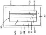
우라늄 수용액은 흐름을 따른(downstream) 화학적 공정들에 대해 큰 장점을 제공한다. 또한, 이들은 냉각하기 쉽고, 연료와 감속재의 우수한 조합을 제공한다. 초기 연구들은 우라늄 니트레이트 용액-UO2(NO3)2을 이용하여 수행되었지만, 우라늄 술페이트 등과 같은 다른 용액들이 고려될 수 있다. 일 구성에서, 용액 내의 염 농도는 100 g의 H2O당 약 66 g의 염이다. 용액은 도 24 및 도 25에 예시된 바와 같이 활성화 셀(410) 내에 위치된다. 용액 이외에, 활성화 셀(410)의 중심에 순수(pure water)로 채워진 더 작은 직경의 실린더(500)가 존재한다. 물의 이 실린더는, 디바이스가 아임계를 유지하는 한편, 여전히 큰 부피의 LEU 용액이 사용되게 하도록 keff의 값으로 하여금 감소되게 한다.Uranium aqueous solutions provide great advantages for downstream chemical processes. In addition, they are easy to cool and provide a good combination of fuel and moderator. Initial studies have been carried out using uranium nitrate solution -UO2 (NO3 )2 , but other solutions such as uranium sulfate can be considered. In one construction, the salt concentration in the solution is a salt of about 100 g per 66 g of H2 O. The solution is located in the
도 24 및 도 25에 예시된 수용액 레이아웃에서, 가장 중심의 실린더(500)는 순수를 포함하며, 실질적으로 환형인 공간(510)을 정의하도록 상호작동하는 튜브와 원통형 벽(505) 사이에 포함되는 우라늄 니트레이트의 수성 혼합물로 둘러싸인다. 타겟 챔버(60, 70)는 다음의 가장 바깥쪽 층이며, 또한 환형이다. 순수, 우라늄 니트레이트의 수성 혼합물, 및 타겟 챔버(60, 70)는 Be 증대기(multiplier)/반사기(420)로 둘러싸인다. 이 경우, 가장 바깥쪽의 층(520)은 탱크(415) 내에 포함된 큰 부피의 D2O이다. D2O는 핵분열부(400a, 400b)로부터 방사선 누출을 감소시키는 감속재로서 작용한다. 도 26 내지 도 29는 유사한 구조의 구성요소들을 예시하지만, 이들은 특정 특징들로 설명되는 바와 같이 공간(volume)들의 일부 또는 전체 내에 상이한 물질들을 포함한다.In the aqueous solution layout illustrated in Figures 24 and 25, the most
우라늄을 조사하는 통상적인 방법은, 이를 우라늄 디옥사이드 펠릿들로 형성하거나, 우라늄 디옥사이드 분말을 용기로 감싸는 것이다. 이들은 원자로 내로 삽입되고, 제거 및 처리 전에 조사된다. 오늘날 사용되는 UO2 분말은 HEU를 이용하지만, LEU를 사용하는 것이 바람직하다. 바람직한 구성에서, 0.95보다 작은 Keff를 제공하는 LEU 및 H2O의 혼합물이 사용된다.A common method of irradiating uranium is to form it into uranium dioxide pellets, or to wrap the uranium dioxide powder in a container. They are inserted into the reactor and irradiated before removal and treatment. The UO2 powders used today use HEU, but it is preferable to use LEU. In a preferred configuration, a mixture of LEU and H2 O is used that provides a Keff of less than 0.95.
도 26 및 도 27은 D2O와 함께 균질한 용액 내에 UO2를 포함하는 활성화 칼럼(410)을 예시한다. 이 구성에서 중심 실린더(500)는 가장 바깥쪽의 층(530)(이 일부분만이 예시됨)에서와 같이 H2O(525)로 채워진다. 제 1 환형 공간(535)은 18 % LEU(20 % 농축) 및 82 % D2O의 용액을 포함한다. 제 2 환형 층(540)은 실질적으로 비워지며, 핵융합부 타겟 챔버들(60, 70)과 일치한다. 중심 실린더(500), 제 1 환형 공간(535), 및 제 2 환형 공간(540)은 Be 층(420)으로 둘러싸이며, 이는 증대기 및 중성자 반사기로서 제공된다.FIGS. 26 and 27 illustrate an
또 다른 구성에서, 수정된 Cintichem 공정에서 LEU 포일들의 화학적 용해에 의해 우라늄으로부터99Mo가 추출된다. 이 공정에서는, 우라늄을 함유한 얇은 포일들이 높은 플럭스 구역의 원자로 내에 배치되고, 몇 시간 동안 조사된 후 제거된다. 상기 포일들은 다양한 용액 내에 용해되고, 다수 화학적 기술들을 통해 처리된다.In another configuration,99 Mo is extracted from uranium by chemical dissolution of LEU foils in a modified Cintichem process. In this process, thin foils containing uranium are placed in the reactor in the high flux zone and removed after being irradiated for several hours. The foils are dissolved in various solutions and processed through multiple chemical techniques.
안전, 비확산, 및 건강의 관점으로부터,99Mo를 생성하는 바람직한 방식은 모 물질98Mo와의 (n,γ) 반응에 의한 것이다. 이는 플루토늄 또는 다른 핵분열 생성물들로부터의 오염 없이99Mo를 발생시킨다. 또한, 이 방법에 의한 생성은 여하한 형태의 우라늄의 일정한 공급을 필요로 하지 않는다. 단점은 모98Mo로부터99Mo를 분리하기 어렵다는 것이며, 이는 발생기 내에서99Mo의 낮은 비활성을 초래한다. 또한, 농축된98Mo이 사용될 경우 그 비용은 상당하다. 그러나, 낮은 비활성의99Mo로부터 높은 순도의99mTc를 추출하는 새로운 용리 기술들의 개발은 상당히 진행되었으며, 이는 가까운 장래에 비용-효율적인 선택이 될 수 있다. 본 명세서에 예시된 하이브리드 원자로(5a, 5b)에서 이 형태의 생성을 구현하기 위해, LEU의 고정된 아임계 조립체(435)가 중성자 플럭스(흔히, UO2)를 증가시키는데 사용될 수 있으며, 모98Mo로부터는 격리될 수 있다. 아임계 조립체(435)는 여전히 핵융합부(10, 11) 내부에 위치되며,99Mo 활성화 칼럼은 아임계 조립체(435) 내에 위치될 것이다.From a safety, non-proliferation, and health point of view, the preferred way to produce99 Mo is by the (n, y) reaction with parent Mo98 Mo. This generates99 Mo without contamination from plutonium or other fission products. Also, production by this method does not require a constant supply of uranium in any form. The disadvantage is that it is difficult to separate99 Mo from Mo98 Mo, resulting in a low inactivity of99 Mo in the generator. Also, the cost is enormous when concentrated98 Mo is used. However, the development of new elution techniques to extract high purity from99m Tc of99 Mo of lower inactive was significantly proceed, which costs in the near future may be an efficient choice. To implement the generation of the form in the hybrid reactor (5a, 5b) illustrated herein, and the
바람직한 구성들에서,98Mo는 (부피에 있어서) 활성화 칼럼(410)의 총 20 %를 차지한다. 도 28 및 도 29에 예시된 바와 같이, 한가운데 실린더(500)는 20 %98Mo 및 H2O의 균질한 혼합물을 포함한다. 제 1 환형 층(555)은 아임계 조립체(435)를 포함하며, 18 % LEU(20 % 농축)/D2O 혼합물로 구성된다. 제 2 환형 층(560)은 실질적으로 비워지며, 핵융합부 타겟 챔버들(60, 70)과 일치한다. 중심 실린더(500), 제 1 환형 공간(555), 및 제 2 환형 공간(560)은 Be 층(420)으로 둘러싸이며, 이는 증대기 및 중성자 반사기로서 제공된다. 가장 바깥쪽의 층(570)(이 일부분만이 예시됨)은 핵분열부(5a, 5b)로부터 빠져나가는 방사선의 양을 감소시키는 물을 포함한다.In the preferred configurations,98 Mo accounts for 20% of the activation column 410 (in volume). As illustrated in FIGS. 28 and 29, the
LEU 경우들에 대해,99Mo의 생성 속도 및 비활성은 1015 n/s로 작동하는 핵융합부(10, 11)를 이용하여 핵분열 수율의 6 %를 계산함으로써 결정되었다. 또한, 다양한 구성들에 대해 Keff가 계산되었다. 표 1은 이 계산들의 결과들을 요약한다.98Mo로부터 생성하는 경우,99Mo의 생성 속도를 결정하기 위해 (n,γ) 검수가 사용되었다. 아래의 표는 하이브리드 원자로(5a, 5b) 내의 다양한 타겟 구성들에 대한 생성 속도를 예시한다.For LEU cases, the production rate and inactivity of99 Mo were determined by calculating 6% of the fission yield using the fusion units (10, 11) operating at 1015 n / s. Keff was also calculated for various configurations. Table 1 summarizes the results of these calculations.In the case of production from98 Mo, (n, γ) inspection was used to determine the production rate of99 Mo. The table below illustrates the generation rates for the various target configurations in the

발생된99Mo의 비활성은 모든 아임계 경우에 대해 비교적 일정하지만, 몇몇 구성들은 실질적으로 더 높은 총 생성 속도를 허용한다. 이는, 이 구성들이 훨씬 더 많은 양의 모 물질을 허용하기 때문이다. 또한,98Mo로부터의99Mo의 생성은 생성된99Mo의 총량에 있어서는 LEU로부터의 생성만큼 우수한 방법이라는 점을 주목할 가치가 있다. 그러나 여전히, LEU 공정이98Mo으로부터99Mo를 분리하는 것보다 핵분열 생성물로부터99Mo를 분리하기가 더 쉽기 때문에 더 유리한 경향이 있으며, 이는 분리 후 이용가능할99Mo의 높은 비활성을 허용한다.The inertness of the generated99 Mo is relatively constant for all subcritical cases, but some configurations allow a substantially higher total production rate. This is because these configurations allow a much greater amount of parent material. It is also worth noting that the production of99 Mo from98 Mo is a better method for production of LEU than for the total amount of99 Mo produced. Still, however, the LEU process tends to be more advantageous because it is easier to separate99 Mo from fission products than to separate99 Mo from98 Mo, which allows a high inertness of99 Mo available after separation.
99Mo를 생성하는데98Mo이 사용되는 구성들에서, 아임계 조립체(435)는 완전히 제거될 수 있다. 하지만, 아임계 조립체(435)가 제거되는 경우, 최종 생성물의 비활성이 상당히 낮아질 것이다. 그러나 여전히, 고도의 발생기들이98Mo 조사로부터 발생하는 낮은 비활성을 사용할 수 있다는 조짐들이 약간 있다. 아임계 증대 없이 하이브리드 원자로(5a, 5b)에 의해 생성된 비활성은 이 기술들 중 일부에 대해 충분히 높다. 또한, U.S.99Mo에 대한 총 수요는 여전히 몇몇 생산 시설들로 충족될 것이며, 이는 핵분열 자유 공정(fission free process)을 허용할 것이다.In configurations where98 Mo is used to generate99 Mo,
예를 들어, 핵융합로(fusion only reactor)의 일 구성에서는 아임계 조립체(435)가 생략되고,98Mo가 활성화 칼럼(410) 내에 위치된다.99Mo의 생성을 강화하기 위해, 핵융합부(11)의 선형 구성에 의해 생성된 더 강력한 이온 빔이 사용된다. 앞서 언급된 구성들에서 필요한 것의 약 10 배인 파워 레벨에서 이온 빔을 작동하는 것이 바람직하다. 이를 달성하기 위해, 상기 빔을 시준하고 바람직하지 않은 빔의 분산을 억제하도록 자기장이 확립된다. 자기장은 상기 빔들에 평행하고 실질적으로 가속기(30) 및 펌핑 시스템(40)을 둘러싸도록 배치되며, 반드시 타겟 챔버(70)로 연장되는 것은 아니다. 이 구성을 이용하는 것은 아임계 조립체(435)에 의해 생성된 증대 효과 없이도 원하는 중성자 플럭스를 제공한다. 이 구성의 한가지 장점은, 원하는 동위원소를 생산하는데 우라늄이 필요하지 않다는 것이다.For example, in one configuration of a fusion only reactor, the
따라서, 본 발명은 특히 의료용 동위원소를 생산하는데 사용되는 새롭고 유용한 하이브리드 원자로(5a, 5b)를 제공한다. 앞서 설명되고 도면들에서 예시된 하이브리드 원자로(5a, 5b)의 구성들은 단지 예시의 방식으로만 제시되며, 본 발명의 개념 및 원리를 제한하는 것으로 의도되지 않는다. 아래의 청구항에서 본 발명의 다양한 특징 및 장점이 설명된다.Thus, the present invention provides novel and useful hybrid reactors (5a, 5b), which are used in particular for the production of medical isotopes. The configurations of the
Claims (35)
Translated fromKorean가스로부터 이온 빔을 생성하도록 작동가능한 이온 소스;
핵융합 반응(fusion reaction)을 통해 중성자들을 생성하도록 상기 이온 빔과 상호작용하는 타겟을 포함한 타겟 챔버(target chamber); 및
상기 타겟 챔버와 근접하여 위치되고, 핵분열 반응(fission reaction) - 상기 핵분열 반응은 중성자 증대(multiplication)를 갖고 아임계 레벨(subcritical level)에서 유지됨 - 을 통해 상기 의료용 동위원소를 생산하도록 상기 중성자들과 상호작용하는 모 물질(parent material) - 상기 모 물질은 수용액(aqueous solution) 내에 있음 -을 포함한 활성화 셀(activation cell)
을 포함하는 하이브리드 반응기.A hybrid reactor operable to produce a medical isotope, the hybrid reactor comprising:
An ion source operable to generate an ion beam from a gas;
A target chamber including a target interacting with the ion beam to produce neutrons through a fusion reaction; And
Wherein the target is located proximate to the target chamber and the fission reaction is performed to produce the medical isotope through a neutron multiplication and maintained at a subcritical level. An interacting parent material - an activation cell containing the parent material in an aqueous solution -
≪ / RTI >
상기 이온 빔을 생성하기 위해, RF 공진(resonance)이 사용되는 하이브리드 반응기.The method according to claim 1,
Wherein a RF resonance is used to generate the ion beam.
상기 이온 소스와 상기 타겟 챔버 사이에 위치되고, 상기 이온 빔의 이온들을 가속시키도록 작동가능한 가속기를 더 포함하는 하이브리드 반응기.The method according to claim 1,
Further comprising an accelerator positioned between the ion source and the target chamber and operable to accelerate ions of the ion beam.
상기 가스는 듀테륨 및 트리튬 중 하나를 포함하고, 상기 타겟은 듀테륨 및 트리튬 중 다른 하나를 포함하는 하이브리드 반응기.The method according to claim 1,
Wherein the gas comprises one of deuterium and tritium, and the target comprises another one of deuterium and tritium.
상기 타겟 챔버는 실질적으로 선형인 긴 타겟 경로를 정의하는 하이브리드 반응기.The method according to claim 1,
Wherein the target chamber defines a long target path that is substantially linear.
상기 긴 타겟 경로의 전체 또는 일부분 내에서 상기 이온 빔을 시준하는 자기장을 정의하도록 위치된 적어도 1 이상의 자석을 더 포함하는 하이브리드 반응기.6. The method of claim 5,
And at least one or more magnets positioned to define a magnetic field that collimates the ion beam within all or a portion of the long target path.
상기 타겟 챔버는 실질적으로 나선형(helical)인 긴 타겟 경로를 정의하는 하이브리드 반응기.The method according to claim 1,
Wherein the target chamber defines a long target path that is substantially helical.
상기 나선형 경로를 따라 상기 이온 빔을 지향하는 자기장을 정의하도록 위치된 적어도 1 이상의 자석을 더 포함하는 하이브리드 반응기.8. The method of claim 7,
And at least one magnet positioned to define a magnetic field that directs the ion beam along the helical path.
상기 이온 소스 및 상기 타겟 챔버는 함께, 전체 또는 부분적으로 복수의 융합로들 중 하나를 정의하는 하이브리드 반응기.The method according to claim 1,
Wherein the ion source and the target chamber together define one of a plurality of fusion paths, in whole or in part.
상기 복수의 융합로들 각각의 타겟 챔버는 실질적으로 원통형 공간을 둘러싸도록 상호작동하는 하이브리드 반응기.10. The method of claim 9,
Wherein the target chambers of each of the plurality of fusion paths cooperate to substantially enclose the cylindrical space.
상기 활성화 셀은 실질적으로 환형이고, 상기 원통형 공간 내에 위치되는 하이브리드 반응기.11. The method of claim 10,
Wherein the activation cell is substantially annular and is located within the cylindrical space.
상기 활성화 셀에 근접하여 위치되는 감쇠기(attenuator);
실질적으로 상기 복수의 타겟 챔버들을 둘러싸고 상기 환형 활성화 셀을 향해 중성자들을 반사시키도록 선택되는 반사기; 및
실질적으로 상기 활성화 셀 및 상기 반사기를 둘러싸는 감속재(moderator)
를 더 포함하는 하이브리드 반응기.12. The method of claim 11,
An attenuator positioned proximate to the activation cell;
A reflector that is selected to substantially surround the plurality of target chambers and reflect neutrons toward the annular activation cell; And
A moderator substantially surrounding the activation cell and the reflector,
≪ / RTI >
상기 모 물질은 저농축235U이고, 상기 의료용 동위원소는99Mo인 하이브리드 반응기.The method according to claim 1,
Wherein the parent material is a low enriched235 U and the medical isotope is99 Mo.
이온 빔을 생성하도록 가스를 여기(excite)시키는 단계;
상기 이온 빔을 가속시키는 단계;
타겟 가스를 포함한 실질적으로 선형인 타겟 경로를 통해 상기 가속된 이온 빔을 통과시키는 단계- 상기 타겟 가스 및 상기 이온들은 자유 중성자들을 생성하도록 핵융합 반응을 통해 반응함 -;
상기 타겟 경로에 인접한 활성화 챔버 내에 모 물질을 위치시키는 단계; 및
상기 의료용 동위원소를 생산하도록 상기 모 물질과 상기 자유 중성자들의 일부를 반응시키는 단계 - 상기 자유 중성자들과 상기 모 물질은 중성자 증대를 갖고 아임계 레벨에서 유지되는 핵분열 반응을 통해 상기 의료용 동위원소를 생산하고, 상기 모 물질은 수용액 내에 있음 -;
를 포함하는 의료용 동위원소 생산 방법.A method for producing medical isotopes comprising:
Exciting the gas to produce an ion beam;
Accelerating the ion beam;
Passing the accelerated ion beam through a substantially linear target path including a target gas, the target gas and the ions reacting through a fusion reaction to produce free neutrons;
Positioning a parent material in an activation chamber adjacent to the target path; And
Reacting the parent material with a portion of the free neutrons to produce the medical isotope, the free neutrons and the parent material producing the medical isotope through a fission reaction with neutron enrichment and maintained at a subcritical level; And the parent material is in an aqueous solution;
≪ / RTI >
RF 방사선이 상기 가스를 여기시키는 의료용 동위원소 생산 방법.15. The method of claim 14,
A method of producing medical isotopes wherein RF radiation excites the gas.
상기 가스는 듀테륨 및 트리튬 중 하나를 포함하고, 상기 타겟 가스는 듀테륨 및 트리튬 중 다른 하나를 포함하는 의료용 동위원소 생산 방법.15. The method of claim 14,
Wherein the gas comprises one of deuterium and tritium, and the target gas comprises another one of deuterium and tritium.
상기 자유 중성자들의 일부를 열중성자(thermal neutron)들로 전환하는 단계 및 상기 모 물질 및 상기 열중성자들 중 일부를 반응시킴으로써, 추가적인 의료용 동위원소를 생산하는 단계를 더 포함하는 의료용 동위원소 생산 방법.15. The method of claim 14,
Further converting the free neutrons to thermal neutrons, and reacting the parent material and some of the thermal neutrons to produce additional medical isotopes.
상기 모 물질은 저농축235U이고, 상기 의료용 동위원소는99Mo인 의료용 동위원소 생산 방법.15. The method of claim 14,
Wherein the parent material is low enriched235 U and the medical isotope is99 Mo.
상기 의료용 동위원소는 핵분열성 물질을 사용하지 않고 생산되는 의료용 동위원소 생산 방법.15. The method of claim 14,
Wherein said medical isotope is produced without the use of a fissile material.
분산을 억제하기 위해 상기 이온 빔을 시준하도록 방위되는 자기장을 확립하는 단계를 더 포함하는 의료용 동위원소 생산 방법.15. The method of claim 14,
Further comprising establishing a magnetic field oriented to collimate the ion beam to inhibit dispersion.
상기 모 물질은98Mo를 포함하고, 상기 의료용 동위원소는99Mo인 의료용 동위원소 생산 방법.20. The method of claim 19,
Wherein the parent material comprises98 Mo and the medical isotope is99 Mo.
상기 타겟 경로의 반경방향 바깥쪽(radially outward)에 위치된 반사기로 상기 중성자들의 일부를 반사시키는 단계;
상기 활성화 챔버에 인접하여 감쇠기를 위치시키는 단계; 및
상기 활성화 챔버 내에서의 상기 핵분열 반응을 강화하도록 상기 중성자들의 일부를 열중성자(thermal neutron)으로 전환하는 단계;
를 더 포함하는 의료용 동위원소 생산 방법.15. The method of claim 14,
Reflecting a portion of the neutrons with a reflector located radially outward of the target path;
Positioning an attenuator adjacent the activation chamber; And
Converting a portion of the neutrons to thermal neutrons to enhance the fission reaction in the activation chamber;
≪ / RTI >
Applications Claiming Priority (3)
| Application Number | Priority Date | Filing Date | Title |
|---|---|---|---|
| US5009608P | 2008-05-02 | 2008-05-02 | |
| US61/050,096 | 2008-05-02 | ||
| PCT/US2009/042587WO2009135163A2 (en) | 2008-05-02 | 2009-05-01 | Device and method for producing medical isotopes |
Related Child Applications (1)
| Application Number | Title | Priority Date | Filing Date |
|---|---|---|---|
| KR1020167015856ADivisionKR20160072846A (en) | 2008-05-02 | 2009-05-01 | Device and method for producing medical isotopes |
Publications (2)
| Publication Number | Publication Date |
|---|---|
| KR20110031278A KR20110031278A (en) | 2011-03-25 |
| KR101673954B1true KR101673954B1 (en) | 2016-11-08 |
Family
ID=41030814
Family Applications (2)
| Application Number | Title | Priority Date | Filing Date |
|---|---|---|---|
| KR1020167015856AWithdrawnKR20160072846A (en) | 2008-05-02 | 2009-05-01 | Device and method for producing medical isotopes |
| KR1020107027045AActiveKR101673954B1 (en) | 2008-05-02 | 2009-05-01 | Device and method for producing medical isotopes |
Family Applications Before (1)
| Application Number | Title | Priority Date | Filing Date |
|---|---|---|---|
| KR1020167015856AWithdrawnKR20160072846A (en) | 2008-05-02 | 2009-05-01 | Device and method for producing medical isotopes |
Country Status (10)
| Country | Link |
|---|---|
| US (4) | US9734926B2 (en) |
| EP (1) | EP2294582B1 (en) |
| JP (3) | JP5793418B2 (en) |
| KR (2) | KR20160072846A (en) |
| CN (2) | CN105575445B (en) |
| CA (1) | CA2723224C (en) |
| ES (1) | ES2695925T3 (en) |
| PL (1) | PL2294582T3 (en) |
| RU (1) | RU2494484C2 (en) |
| WO (1) | WO2009135163A2 (en) |
Families Citing this family (58)
| Publication number | Priority date | Publication date | Assignee | Title |
|---|---|---|---|---|
| EP2236016B1 (en)* | 2007-12-28 | 2017-08-09 | Phoenix Nuclear Labs LLC | High energy proton or neutron source |
| KR20160072846A (en) | 2008-05-02 | 2016-06-23 | 샤인 메디컬 테크놀로지스, 인크. | Device and method for producing medical isotopes |
| US9196388B2 (en)* | 2009-12-07 | 2015-11-24 | Varian Medical Systems, Inc. | System and method for generating molybdenum-99 and metastable technetium-99, and other isotopes |
| DK2513640T3 (en)* | 2009-12-15 | 2020-04-27 | Phoenix Llc | Method and apparatus for carrying out active neutron interrogation of containers |
| US10978214B2 (en)* | 2010-01-28 | 2021-04-13 | SHINE Medical Technologies, LLC | Segmented reaction chamber for radioisotope production |
| US9177679B2 (en)* | 2010-02-11 | 2015-11-03 | Uchicago Argonne, Llc | Accelerator-based method of producing isotopes |
| RU2439727C1 (en)* | 2010-08-05 | 2012-01-10 | Федеральное государственное бюджетное учреждение "Национальный исследовательский центр "Курчатовский институт" | Method to produce radionuclide bismuth-212 |
| US8414685B2 (en)* | 2010-09-08 | 2013-04-09 | Westinghouse Electric Company Llc | System and method for removal of dissolved gases in makeup water of a water-cooled nuclear reactor |
| US8873694B2 (en)* | 2010-10-07 | 2014-10-28 | Westinghouse Electric Company Llc | Primary neutron source multiplier assembly |
| US8437974B2 (en) | 2010-10-08 | 2013-05-07 | Westinghouse Electric Company Llc | Calibration detection system and method |
| US8670519B2 (en) | 2010-10-11 | 2014-03-11 | Westinghouse Electric Company Llc | Nuclear fuel assembly hold down spring |
| US10734126B2 (en) | 2011-04-28 | 2020-08-04 | SHINE Medical Technologies, LLC | Methods of separating medical isotopes from uranium solutions |
| US8415646B2 (en)* | 2011-08-04 | 2013-04-09 | California Institute Of Technology | Production of MeV micro beams of protons for medical applications |
| US10332646B2 (en)* | 2011-12-05 | 2019-06-25 | Wisconsin Alumni Research Foundation | Apparatus and method for generating medical isotopes |
| CN104321623B (en)* | 2012-04-05 | 2018-11-30 | 阳光医疗技术公司 | Aqueous component and control method |
| CN104488037B (en)* | 2012-06-15 | 2016-12-21 | 登特国际研究有限公司 | Apparatus and method for for transmutation of element |
| JP2014025898A (en)* | 2012-07-30 | 2014-02-06 | Quan Japan Inc | Nuclear fuel production apparatus and nuclear fuel production method |
| US9330800B2 (en)* | 2012-12-03 | 2016-05-03 | Wisconsin Alumni Research Foundation | Dry phase reactor for generating medical isotopes |
| US9997267B2 (en)* | 2013-02-13 | 2018-06-12 | Battelle Memorial Institute | Nuclear reactor target assemblies, nuclear reactor configurations, and methods for producing isotopes, modifying materials within target material, and/or characterizing material within a target material |
| US10049773B2 (en) | 2013-04-03 | 2018-08-14 | Lockheed Martin Corporation | Heating plasma for fusion power using neutral beam injection |
| US9941024B2 (en)* | 2013-04-03 | 2018-04-10 | Lockheed Martin Corporation | Heating plasma for fusion power using electromagnetic waves |
| US9959942B2 (en) | 2013-04-03 | 2018-05-01 | Lockheed Martin Corporation | Encapsulating magnetic fields for plasma confinement |
| US9928926B2 (en) | 2013-04-03 | 2018-03-27 | Lockheed Martin Corporation | Active cooling of structures immersed in plasma |
| US9934876B2 (en) | 2013-04-03 | 2018-04-03 | Lockheed Martin Corporation | Magnetic field plasma confinement for compact fusion power |
| US9959941B2 (en) | 2013-04-03 | 2018-05-01 | Lockheed Martin Corporation | System for supporting structures immersed in plasma |
| CN104376889A (en)* | 2013-08-12 | 2015-02-25 | 中国核动力研究设计院 | Reactor core of medical isotope production reactor |
| KR101581897B1 (en) | 2013-10-02 | 2015-12-31 | 기초과학연구원 | Target assembly for generating rare isotopes |
| WO2015199770A2 (en)* | 2014-03-19 | 2015-12-30 | Phoenix Nuclear Labs Llc | Fast burst and steady-state intense neutron source |
| US20160042826A1 (en)* | 2014-08-06 | 2016-02-11 | Research Triangle Institute | High efficiency neutron capture product production |
| CA2860128A1 (en)* | 2014-08-20 | 2016-02-20 | Ad Maiora Llc | Exothermic transmutation method |
| CN104378905A (en)* | 2014-08-29 | 2015-02-25 | 常州博锐恒电子科技有限公司 | High current neutron generating device |
| US10867715B2 (en) | 2014-11-17 | 2020-12-15 | Triad National Security, Llc | Apparatus for preparing medical radioisotopes |
| US10930407B2 (en)* | 2014-11-21 | 2021-02-23 | Gary M. Sandquist | Productions of radioisotopes |
| US10141079B2 (en)* | 2014-12-29 | 2018-11-27 | Terrapower, Llc | Targetry coupled separations |
| WO2016120120A1 (en)* | 2015-01-29 | 2016-08-04 | Areva Gmbh | Irradiation target for radioisotope production, method for preparing and use of the irradiation target |
| PL3289591T3 (en)* | 2015-04-30 | 2019-10-31 | Framatome Gmbh | Radionuclide generation system and method of producing radionuclides |
| CN106128539B (en)* | 2016-08-30 | 2019-01-22 | 中广核研究院有限公司 | A kind of system producing medical short-lived phase radioactive source using pressurized-water reactor nuclear power plant |
| CA3229072A1 (en) | 2017-01-18 | 2018-08-09 | Shine Technologies, Llc | High power ion beam generator systems and methods |
| US20180244535A1 (en) | 2017-02-24 | 2018-08-30 | BWXT Isotope Technology Group, Inc. | Titanium-molybdate and method for making the same |
| US11257603B2 (en)* | 2017-04-24 | 2022-02-22 | Advanced Accelerator Applications | Accelerator-driven neutron activator for brachytherapy |
| US10362666B2 (en)* | 2017-05-25 | 2019-07-23 | Uchicago Argonne, Llc | Compac carbon ion LINAC |
| US20180374588A1 (en)* | 2017-06-16 | 2018-12-27 | Muons, Inc. | Method and apparatus for producing radioisotopes using fractional distillation |
| CN107342114A (en)* | 2017-06-30 | 2017-11-10 | 中国科学院近代物理研究所 | Target assembly, isotope or neutron generation device and the method for producing isotope or neutron |
| CN107863162B (en)* | 2017-11-28 | 2019-09-24 | 中国科学院近代物理研究所 | The method that reactor is transformed into critical state from subcritical state |
| CA3096470A1 (en)* | 2018-04-11 | 2019-10-17 | Phoenix Llc | Neutron imaging systems and methods |
| CN108470595A (en)* | 2018-05-24 | 2018-08-31 | 河南太粒科技有限公司 | A kind of small-sized high current neutron source apparatus based on linear accelerator |
| KR102801596B1 (en) | 2018-06-06 | 2025-04-30 | 피닉스 뉴트론 이미징 엘엘씨 | Ion beam target assembly for neutron generation |
| EP3637436A1 (en)* | 2018-10-12 | 2020-04-15 | ASML Netherlands B.V. | Enrichment and radioisotope production |
| CN109443874B (en)* | 2018-11-22 | 2021-07-20 | 核工业北京化工冶金研究院 | Preparation method of standard substance of uranium and impurity elements in triuranium octoxide |
| RU2734429C1 (en)* | 2020-02-17 | 2020-10-16 | Федеральное государственное бюджетное учреждение "Петербургский институт ядерной физики им. Б.П. Константинова Национального исследовательского центра "Курчатовский институт" (НИЦ "Курчатовский институт-ПИЯФ") | Method of generating pb-212 generator radionuclide for producing a therapeutic agent based on bi-212 radionuclide |
| US11832374B1 (en) | 2020-10-01 | 2023-11-28 | Consolidated Nuclear Security, LLC | Method of making an annular radioisotope target having a helical coil-shaped foil ribbon between cladding tubes |
| WO2022125528A1 (en)* | 2020-12-08 | 2022-06-16 | Shine Technologies, Llc | Isothermal ion source with auxiliary heaters |
| JP2024518717A (en)* | 2021-04-16 | 2024-05-02 | ザ エクストリーム ライト インフラストラクチャー エリック | Nuclear target, method for inducing a nuclear reaction and device suitable for carrying out the method - Patents.com |
| US11774375B1 (en) | 2022-04-15 | 2023-10-03 | Phoenix, Llc | Re-entrant cones for moderator chamber of a neutron imaging system |
| US12267942B2 (en) | 2022-09-23 | 2025-04-01 | Shine Technologies, Llc | Cooling plate assembly for plasma windows positioned in a beam accelerator system |
| EP4581911A1 (en)* | 2022-10-05 | 2025-07-09 | TAE Technologies, Inc. | Lithium target with intermediate layer |
| WO2024081327A2 (en)* | 2022-10-11 | 2024-04-18 | Shine Tecyhnologies, Llc | Multi-beam systems with plasma windows and a central target chamber |
| WO2025122731A1 (en)* | 2023-12-05 | 2025-06-12 | Shine Technologies, Llc | Multi-beam spallation source for intense neutron generation |
Citations (2)
| Publication number | Priority date | Publication date | Assignee | Title |
|---|---|---|---|---|
| JP2002214395A (en)* | 2001-01-12 | 2002-07-31 | Hitachi Ltd | Isotope nuclide production equipment |
| US20050082469A1 (en)* | 1997-06-19 | 2005-04-21 | European Organization For Nuclear Research | Neutron-driven element transmuter |
Family Cites Families (170)
| Publication number | Priority date | Publication date | Assignee | Title |
|---|---|---|---|---|
| US2161985A (en)* | 1934-03-12 | 1939-06-13 | Szilard Leo | Process of producing radio-active elements |
| GB829093A (en) | 1945-01-06 | 1960-02-24 | Atomic Energy Authority Uk | Recovery of uranium by precipitation as peroxide |
| NL274922A (en) | 1955-06-14 | |||
| US2837476A (en) | 1956-01-27 | 1958-06-03 | Harold M Busey | Steam stirred homogeneous nuclear reactor |
| NL113540C (en) | 1956-08-06 | |||
| BE567050A (en)* | 1957-04-24 | |||
| US3860482A (en) | 1957-09-25 | 1975-01-14 | Atomic Energy Commission | Reactor reactivity control by coolant passage coating |
| US2992333A (en) | 1958-04-03 | 1961-07-11 | High Voltage Engineering Corp | Compact neutron source |
| US3030543A (en) | 1958-04-15 | 1962-04-17 | John S Luce | Method and apparatus for trapping ions in a magnetic field |
| US3079319A (en) | 1958-09-02 | 1963-02-26 | Westinghouse Electric Corp | Neutronic reactor fuel handling system |
| GB869451A (en) | 1958-10-25 | 1961-05-31 | Asea Ab | Fuel composition for aqueous homogeneous nuclear reactors |
| BE627008A (en) | 1960-02-26 | |||
| US3085966A (en) | 1960-11-08 | 1963-04-16 | North American Aviation Inc | Liquid homogeneous fuel element and reactor therefor |
| US3255092A (en) | 1961-03-24 | 1966-06-07 | Gen Dynamics Corp | Control rods |
| US3418206A (en) | 1963-04-29 | 1968-12-24 | Boeing Co | Particle accelerator |
| US3276965A (en) | 1963-06-17 | 1966-10-04 | Internuclear Company | Single pass superheat reactor |
| US3218235A (en) | 1963-12-09 | 1965-11-16 | Arthur W Ehler | Method and apparatus for producing a magnetically confined hot dense plasma |
| NL289180A (en) | 1965-03-11 | |||
| US4147590A (en) | 1965-09-01 | 1979-04-03 | The United States Of America As Represented By The United States Department Of Energy | Nuclear propulsion apparatus with alternate reactor segments |
| US3320176A (en) | 1966-04-01 | 1967-05-16 | Babcock & Wilcox Co | Method of producing ceramic nuclear fuel material having incorporated therein burnable poison |
| US3386883A (en) | 1966-05-13 | 1968-06-04 | Itt | Method and apparatus for producing nuclear-fusion reactions |
| US3473056A (en) | 1967-08-09 | 1969-10-14 | Nat Electrostatics Corp | Power transmission system for high voltage accelerators |
| US3530497A (en) | 1968-04-24 | 1970-09-22 | Itt | Apparatus for generating fusion reactions |
| DE1816459B1 (en) | 1968-12-21 | 1970-06-25 | Kernforschung Gmbh Ges Fuer | Neutron generator |
| US3676672A (en) | 1969-02-03 | 1972-07-11 | Benjamin B Meckel | Large diameter ion beam apparatus with an apertured plate electrode to maintain uniform flux density across the beam |
| US3617908A (en)* | 1969-02-24 | 1971-11-02 | Henry Greber | Charged particle accelerator with single or multimode operation |
| BE758571A (en) | 1969-11-06 | 1971-04-16 | Euratom | HIGH FREQUENCY PLASMA GENERATOR |
| GB1325685A (en) | 1969-12-23 | 1973-08-08 | Nat Res Dev | Neutron generators |
| US3668066A (en) | 1970-02-18 | 1972-06-06 | Atomic Energy Commission | Dynamic stabilizer for plasma instabilities to improve plasma confinement and to increase plasma density |
| US3624240A (en) | 1970-03-24 | 1971-11-30 | Atomic Energy Commission | Feedback stabilization of a magnetically confined plasma |
| US3746859A (en) | 1970-04-22 | 1973-07-17 | Atomic Energy Commission | High intensity neutron source |
| US3634704A (en) | 1970-09-02 | 1972-01-11 | Atomic Energy Commission | Apparatus for the production of highly stripped ions |
| US3718836A (en) | 1970-11-18 | 1973-02-27 | Itt | Multipactor ion generator |
| US3713967A (en) | 1971-06-18 | 1973-01-30 | Atomic Energy Commission | Energetic neutral particle injection system for controlled fusion reactor |
| US3799883A (en)* | 1971-06-30 | 1974-03-26 | Union Carbide Corp | Production of high purity fission product molybdenum-99 |
| US3719893A (en) | 1971-12-23 | 1973-03-06 | Us Navy | System and method for accelerating charged particles utilizing pulsed hollow beam electrons |
| US3992625A (en) | 1973-12-27 | 1976-11-16 | Jersey Nuclear-Avco Isotopes, Inc. | Method and apparatus for extracting ions from a partially ionized plasma using a magnetic field gradient |
| US3925676A (en) | 1974-07-31 | 1975-12-09 | Ca Atomic Energy Ltd | Superconducting cyclotron neutron source for therapy |
| US4008411A (en) | 1975-07-08 | 1977-02-15 | The United States Of America As Represented By The United States Energy Research And Development Administration | Production of 14 MeV neutrons by heavy ions |
| US4137012A (en) | 1976-11-03 | 1979-01-30 | S.A.E.S. Getters S.P.A. | Modular getter pumps |
| US4202725A (en) | 1978-03-08 | 1980-05-13 | Jarnagin William S | Converging beam fusion system |
| US4314879A (en) | 1979-03-22 | 1982-02-09 | The United States Of America As Represented By The United States Department Of Energy | Production of field-reversed mirror plasma with a coaxial plasma gun |
| DE3003088A1 (en) | 1980-01-29 | 1981-07-30 | Alkem Gmbh, 6450 Hanau | METHOD FOR PURIFYING A NITRIC ACID U / PU SOLUTION |
| US4311912A (en) | 1980-05-08 | 1982-01-19 | Mobil Oil Corporation | Neutron accelerator tube having improved target section |
| US4650630A (en) | 1982-02-11 | 1987-03-17 | Boyer John L | Process and apparatus for producing nuclear fusion energy |
| US4663110A (en)* | 1982-03-12 | 1987-05-05 | Ga Technologies Inc. | Fusion blanket and method for producing directly fabricable fissile fuel |
| DE3225751C1 (en) | 1982-07-09 | 1984-01-26 | Kernforschungszentrum Karlsruhe Gmbh, 7500 Karlsruhe | Device for separating the gaseous hydrogen isotopes |
| US4800060A (en) | 1982-08-03 | 1989-01-24 | Yeda Research & Development Co., Ltd. | Window assembly for positron emitter |
| JPS5968143A (en) | 1982-10-08 | 1984-04-18 | Fujitsu Ltd | Emitter tip for field ionization gas ion source |
| US4529571A (en) | 1982-10-27 | 1985-07-16 | The United States Of America As Represented By The United States Department Of Energy | Single-ring magnetic cusp low gas pressure ion source |
| US4793961A (en) | 1983-07-26 | 1988-12-27 | The United States Of America As Represented By The Department Of Energy | Method and source for producing a high concentration of positively charged molecular hydrogen or deuterium ions |
| US4826646A (en) | 1985-10-29 | 1989-05-02 | Energy/Matter Conversion Corporation, Inc. | Method and apparatus for controlling charged particles |
| SE450060B (en) | 1985-11-27 | 1987-06-01 | Rolf Lennart Stenbacka | PROCEDURE TO ASTAD MERGER REACTIONS, AND MERGER REACTOR DEVICE |
| USRE34575E (en) | 1986-04-30 | 1994-04-05 | Science Reseach Corporation | Electrostatic ion accelerator |
| JPS62283296A (en) | 1986-05-29 | 1987-12-09 | Kawaju Kensa Service Kk | Method and device for inspecting spherical tank |
| US4752432A (en) | 1986-06-18 | 1988-06-21 | Computer Technology And Imaging, Inc. | Device and process for the production of nitrogen-13 ammonium ion from carbon-13/fluid slurry target |
| FR2630576B1 (en) | 1988-04-26 | 1990-08-17 | Realisations Nucleaires Et | DEVICE FOR IMPROVING THE LIFETIME AND RELIABILITY OF A HIGH-FLOW SEALED NEUTRONIC TUBE |
| FR2637727A1 (en) | 1988-10-07 | 1990-04-13 | Realisations Nucleaires Et | NEUTRONIC TUBE WITH ION SOURCE WITH ELECTROSTATIC ELECTRONIC CONFINEMENT |
| US5037602A (en) | 1989-03-14 | 1991-08-06 | Science Applications International Corporation | Radioisotope production facility for use with positron emission tomography |
| US4976938A (en) | 1989-07-14 | 1990-12-11 | The United States Of America As Represented By The United States Department Of Energy | Hydrogen isotope separation utilizing bulk getters |
| US5126574A (en) | 1989-10-10 | 1992-06-30 | The United States Of America As Represented By The Secretary Of Commerce | Microtip-controlled nanostructure fabrication and multi-tipped field-emission tool for parallel-process nanostructure fabrication |
| JPH03190097A (en) | 1989-12-20 | 1991-08-20 | Hitachi Ltd | Neutron particle incident device |
| WO1991014268A1 (en) | 1990-03-07 | 1991-09-19 | Combustion Engineering, Inc. | Pressurized water reactor fuel |
| FR2666477A1 (en) | 1990-08-31 | 1992-03-06 | Sodern | HIGH FLOW NEUTRONIC TUBE. |
| EP0535235B1 (en) | 1991-04-17 | 1996-08-07 | Nkk Corporation | Method of synthesizing 13N-ammonia |
| US5280505A (en) | 1991-05-03 | 1994-01-18 | Science Research Laboratory, Inc. | Method and apparatus for generating isotopes |
| DE4231997C1 (en) | 1992-09-24 | 1994-01-05 | Kernforschungsz Karlsruhe | Process for separating split molybdenum |
| JPH06160595A (en) | 1992-11-16 | 1994-06-07 | Ishikawajima Harima Heavy Ind Co Ltd | Low speed positron generator |
| US5596611A (en)* | 1992-12-08 | 1997-01-21 | The Babcock & Wilcox Company | Medical isotope production reactor |
| JP3124140B2 (en) | 1992-12-28 | 2001-01-15 | 株式会社東芝 | In-core equipment for fusion reactors |
| US5468355A (en) | 1993-06-04 | 1995-11-21 | Science Research Laboratory | Method for producing radioisotopes |
| US5515234A (en) | 1993-06-30 | 1996-05-07 | Texas Instruments Incorporated | Antistatic protector and method |
| FR2710782A1 (en) | 1993-09-29 | 1995-04-07 | Sodern | Neutron tube with magnetic confinement of electrons by permanent magnets and its manufacturing process. |
| FR2711835B1 (en) | 1993-10-21 | 1995-11-24 | Framatome Sa | Fast neutron nuclear reactor in which at least one moderating element is incorporated into reactor assemblies. |
| EP0725967B2 (en) | 1993-10-29 | 2003-07-09 | Carlo Rubbia | An energy amplifier for "clean" nuclear energy production driven by a particle beam accelerator |
| JP3145555B2 (en) | 1994-02-28 | 2001-03-12 | 核燃料サイクル開発機構 | Radioactive waste annihilation treatment method using nuclear fusion |
| US5443732A (en) | 1994-04-01 | 1995-08-22 | Westinghouse Electric Corporation | Boron isotope separation using continuous ion exchange chromatography |
| US5482865A (en) | 1994-06-10 | 1996-01-09 | Associated Universities, Inc. | Apparatus and method for preparing oxygen-15 labeled water H2 [15 O] in an injectable form for use in positron emission tomography |
| JP3428150B2 (en) | 1994-07-08 | 2003-07-22 | 株式会社日立製作所 | Light water reactor core and fuel assemblies |
| AU2628595A (en) | 1994-07-21 | 1996-02-22 | Gregory Lowell Millspaugh | Method of and system for controlling energy, including in fusion reactors |
| US20030223528A1 (en) | 1995-06-16 | 2003-12-04 | George Miley | Electrostatic accelerated-recirculating-ion fusion neutron/proton source |
| US6011825A (en) | 1995-08-09 | 2000-01-04 | Washington University | Production of 64 Cu and other radionuclides using a charged-particle accelerator |
| US5586153A (en) | 1995-08-14 | 1996-12-17 | Cti, Inc. | Process for producing radionuclides using porous carbon |
| JPH09113693A (en) | 1995-10-13 | 1997-05-02 | N K K Plant Kensetsu Kk | Method for producing 15O-containing gas as radionuclide |
| US5745536A (en) | 1996-06-05 | 1998-04-28 | Sandia Corporation | Secondary electron ion source neutron generator |
| US5920601A (en) | 1996-10-25 | 1999-07-06 | Lockheed Martin Idaho Technologies Company | System and method for delivery of neutron beams for medical therapy |
| US5870447A (en) | 1996-12-30 | 1999-02-09 | Brookhaven Science Associates | Method and apparatus for generating low energy nuclear particles |
| US5898279A (en) | 1997-01-08 | 1999-04-27 | Kettering Medical Center | Cyclotron monitoring system and method |
| US6541786B1 (en) | 1997-05-12 | 2003-04-01 | Cymer, Inc. | Plasma pinch high energy with debris collector |
| US5854531A (en)* | 1997-05-30 | 1998-12-29 | Science Applications International Corporation | Storage ring system and method for high-yield nuclear production |
| JPH1157043A (en) | 1997-08-21 | 1999-03-02 | Mitsubishi Heavy Ind Ltd | Neutron-irradiation apparatus for treatment and method therefor |
| US5910971A (en)* | 1998-02-23 | 1999-06-08 | Tci Incorporated | Method and apparatus for the production and extraction of molybdenum-99 |
| US5977554A (en) | 1998-03-23 | 1999-11-02 | The Penn State Research Foundation | Container for transporting antiprotons |
| SE513192C2 (en) | 1998-09-29 | 2000-07-24 | Gems Pet Systems Ab | Procedures and systems for HF control |
| JP3122081B2 (en) | 1998-11-25 | 2001-01-09 | 石油公団 | Neutron generator tube |
| JP3658235B2 (en) | 1999-03-30 | 2005-06-08 | キヤノン株式会社 | Electron gun, drawing apparatus using electron gun, and electron beam application apparatus |
| JP2000284096A (en) | 1999-03-31 | 2000-10-13 | Hitachi Ltd | Production method for radioactive isotope and its production device |
| WO2001003142A2 (en) | 1999-04-23 | 2001-01-11 | Adna Corporation | Accelerator-driven energy generation from thorium |
| US6925137B1 (en) | 1999-10-04 | 2005-08-02 | Leon Forman | Small neutron generator using a high current electron bombardment ion source and methods of treating tumors therewith |
| JP2003513418A (en) | 1999-10-27 | 2003-04-08 | ジェイ エム エー アール リサーチ、インク | Method and radiation generation system using micro target |
| US6544606B1 (en) | 2000-01-11 | 2003-04-08 | Nac International | Systems and methods for storing fissile materials |
| US6337055B1 (en) | 2000-01-21 | 2002-01-08 | Tci Incorporated | Inorganic sorbent for molybdenum-99 extraction from irradiated uranium solutions and its method of use |
| WO2001063623A1 (en) | 2000-02-23 | 2001-08-30 | The University Of Alberta, The University Of British Columbia, Carleton University, Simon Fraser University, The University Of Victoria Doing Business As Triumf | System and method for the production of 18f-fluoride |
| US6593539B1 (en) | 2000-02-25 | 2003-07-15 | George Miley | Apparatus and methods for controlling charged particles |
| ATE438922T1 (en) | 2000-03-16 | 2009-08-15 | Hitachi Ltd | DEVICE FOR GENERATING A FLOW OF CHARGE CARRIERS |
| JP2001338800A (en) | 2000-05-30 | 2001-12-07 | Hitachi Ltd | Neutron generator |
| JP2002062388A (en)* | 2000-08-21 | 2002-02-28 | Hitachi Ltd | Inertial electrostatic confinement fusion device and radioisotope manufacturing system |
| US6917044B2 (en) | 2000-11-28 | 2005-07-12 | Behrouz Amini | High power high yield target for production of all radioisotopes for positron emission tomography |
| US6482368B2 (en) | 2000-12-19 | 2002-11-19 | Delphi Technologies, Inc. | Non-thermal plasma reactor for lower power consumption |
| RU2200997C2 (en)* | 2001-01-10 | 2003-03-20 | Российский научный центр "Курчатовский институт" | Method for producing molybdenum radioisotope |
| US6664740B2 (en) | 2001-02-01 | 2003-12-16 | The Regents Of The University Of California | Formation of a field reversed configuration for magnetic and electrostatic confinement of plasma |
| EP1233425B1 (en) | 2001-02-16 | 2006-11-15 | Framatome ANP GmbH | Nuclear reactor, in particular research or test reactor |
| US6907097B2 (en) | 2001-03-16 | 2005-06-14 | The Regents Of The University Of California | Cylindrical neutron generator |
| US20020150193A1 (en) | 2001-03-16 | 2002-10-17 | Ka-Ngo Leung | Compact high flux neutron generator |
| US6611106B2 (en) | 2001-03-19 | 2003-08-26 | The Regents Of The University Of California | Controlled fusion in a field reversed configuration and direct energy conversion |
| RU2187336C1 (en)* | 2001-06-01 | 2002-08-20 | Государственное унитарное предприятие Государственный научный центр Российской Федерации Физико-энергетический институт им. акад. А.И.Лейпунского | Method of producing preparation based on strontium-89 |
| US6567492B2 (en) | 2001-06-11 | 2003-05-20 | Eastern Isotopes, Inc. | Process and apparatus for production of F-18 fluoride |
| GB0120280D0 (en) | 2001-08-21 | 2001-10-17 | Sved John | Low degradation rate linear geometry neutron generator appartus using plasma gas target |
| GB0125951D0 (en) | 2001-10-30 | 2001-12-19 | British Nuclear Fuels Plc | Process for controlling valence states |
| EP1321948A1 (en) | 2001-12-21 | 2003-06-25 | Ion Beam Applications S.A. | Method and device for generating radioisotopes from a target |
| US6922455B2 (en)* | 2002-01-28 | 2005-07-26 | Starfire Industries Management, Inc. | Gas-target neutron generation and applications |
| US7342988B2 (en) | 2002-02-06 | 2008-03-11 | The Regents Of The University Of California | Neutron tubes |
| US6777699B1 (en) | 2002-03-25 | 2004-08-17 | George H. Miley | Methods, apparatus, and systems involving ion beam generation |
| US6870894B2 (en)* | 2002-04-08 | 2005-03-22 | The Regents Of The University Of California | Compact neutron generator |
| US20040100214A1 (en) | 2002-05-13 | 2004-05-27 | Karl Erdman | Particle accelerator assembly with high power gas target |
| WO2003099374A2 (en) | 2002-05-21 | 2003-12-04 | Duke University | Batch target and method for producing radionuclide |
| EP1429345A1 (en) | 2002-12-10 | 2004-06-16 | Ion Beam Applications S.A. | Device and method of radioisotope production |
| US20090316850A1 (en)* | 2003-06-19 | 2009-12-24 | Langenbrunner James R | Generating short-term criticality in a sub-critical reactor |
| JP2005127800A (en) | 2003-10-22 | 2005-05-19 | Toshiba Corp | Electron beam irradiation apparatus, irradiation method, and electron beam drawing apparatus |
| EP1569243A1 (en)* | 2004-02-20 | 2005-08-31 | Ion Beam Applications S.A. | Target device for producing a radioisotope |
| US20060017411A1 (en) | 2004-06-17 | 2006-01-26 | Accsys Technology, Inc. | Mobile/transportable PET radioisotope system with omnidirectional self-shielding |
| JP4980900B2 (en) | 2004-06-29 | 2012-07-18 | トライアンフ,オペレーティング アズ ア ジョイント ヴェンチャー バイ ザ ガバナーズ オブ ザ ユニバーシティ オブ アルバータ,ザ ユニバーシティ オブ ブリティッシュ コロンビア,カールトン | Target assembly |
| US20060023829A1 (en) | 2004-08-02 | 2006-02-02 | Battelle Memorial Institute | Medical radioisotopes and methods for producing the same |
| EP1800315B1 (en) | 2004-08-12 | 2008-04-02 | John Sved | Proton generator apparatus for isotope production |
| US20060062342A1 (en) | 2004-09-17 | 2006-03-23 | Cyclotron Partners, L.P. | Method and apparatus for the production of radioisotopes |
| EP1807844B1 (en) | 2004-09-28 | 2010-05-19 | Soreq Nuclear Research Center Israel Atomic Energy Commission | Method and system for production of radioisotopes |
| US20110176648A1 (en)* | 2004-10-08 | 2011-07-21 | Rowland Mark S | Portable low energy neutron source for high sensitivity material characterization |
| US7526058B2 (en) | 2004-12-03 | 2009-04-28 | General Electric Company | Rod assembly for nuclear reactors |
| US7419604B1 (en) | 2004-12-29 | 2008-09-02 | University Of Kentucky Research Foundation | Use of boron compounds to precipitate uranium from water |
| US7235216B2 (en) | 2005-05-01 | 2007-06-26 | Iba Molecular North America, Inc. | Apparatus and method for producing radiopharmaceuticals |
| KR100643794B1 (en) | 2005-07-29 | 2006-11-10 | 한국원자력연구소 | Plate-like fuel in which coarse particles of gamma-like or M-based alloys are regularly arranged and a method of manufacturing the same |
| WO2007002455A2 (en) | 2005-06-23 | 2007-01-04 | The Regents Of The University Of California | Helicon plasma source with permanent magnets |
| KR20080045673A (en) | 2005-06-29 | 2008-05-23 | 유니버시티 오브 휴스턴 | Compact neutron generator for active nuclear material detection |
| RU2352003C2 (en) | 2005-08-18 | 2009-04-10 | Лев Николаевич Максимов | Amorphised nuclear fuel |
| JP4099187B2 (en) | 2005-09-30 | 2008-06-11 | 株式会社日立製作所 | Radioisotope production apparatus and target recycling method |
| ITCO20050028A1 (en) | 2005-11-11 | 2007-05-12 | Fond Per Adroterapia Oncologica | COMPLEX OF ACCELERATORS OF PROTON TILES IN PARTICULAR FOR MEDICAL USE |
| JP2007165250A (en) | 2005-12-16 | 2007-06-28 | Hitachi Ltd | Microwave ion source, linear accelerator system, accelerator system, medical accelerator system, high energy beam application device, neutron generator, ion beam process device, microwave plasma source and plasma process device |
| DE102005061560A1 (en) | 2005-12-22 | 2007-07-05 | Siemens Ag | Process for the production of radioactive isotopes for positron emission tomography |
| US20070160176A1 (en) | 2006-01-06 | 2007-07-12 | Ryoichi Wada | Isotope generator |
| US20080224106A1 (en) | 2006-09-08 | 2008-09-18 | Michael Ernest Johnson | Process for treating compositions containing uranium and plutonium |
| JP4618732B2 (en) | 2006-10-20 | 2011-01-26 | 独立行政法人 日本原子力研究開発機構 | Method and apparatus for manufacturing radioactive molybdenum |
| WO2009052330A1 (en) | 2007-10-16 | 2009-04-23 | Dent William V Jr | Apparatus and process for generating a neutron beam |
| US8891723B2 (en) | 2007-11-15 | 2014-11-18 | State of Oregon Acting by and Through The State Board of Higher Education on Behalf or Oregon State University, The Oregon State University | Stable startup system for a nuclear reactor |
| US7978804B2 (en) | 2007-12-10 | 2011-07-12 | Schlumberger Technology Corporation | Low power neutron generators |
| US8437443B2 (en) | 2008-02-21 | 2013-05-07 | Ge-Hitachi Nuclear Energy Americas Llc | Apparatuses and methods for production of radioisotopes in nuclear reactor instrumentation tubes |
| EP2236016B1 (en) | 2007-12-28 | 2017-08-09 | Phoenix Nuclear Labs LLC | High energy proton or neutron source |
| EP2250649B1 (en) | 2008-02-05 | 2012-05-09 | The Curators Of The University Of Missouri | Radioisotope production and treatment of solution of target material |
| EP2263237B1 (en) | 2008-02-27 | 2017-08-23 | Starfire Industries LLC | Method and system for in situ depositon and regeneration of high efficiency target materials for long life nuclear reaction devices |
| US8767905B2 (en) | 2008-03-07 | 2014-07-01 | Babcock & Wilcox Technical Services Group, Inc. | Combinatorial heterogeneous-homogeneous reactor |
| KR20160072846A (en) | 2008-05-02 | 2016-06-23 | 샤인 메디컬 테크놀로지스, 인크. | Device and method for producing medical isotopes |
| US20090279658A1 (en) | 2008-05-09 | 2009-11-12 | Ottawa Valley Research Associates Ltd. | Molten salt nuclear reactor |
| US8475747B1 (en) | 2008-06-13 | 2013-07-02 | U.S. Department Of Energy | Processing fissile material mixtures containing zirconium and/or carbon |
| US20100063344A1 (en) | 2008-09-11 | 2010-03-11 | Kotschenreuther Michael T | Fusion neutron source for fission applications |
| US9357629B2 (en) | 2009-01-21 | 2016-05-31 | Schlumberger Technology Corporation | Neutron generator |
| US8488734B2 (en)* | 2009-08-28 | 2013-07-16 | The Invention Science Fund I, Llc | Nuclear fission reactor, a vented nuclear fission fuel module, methods therefor and a vented nuclear fission fuel module system |
| US10978214B2 (en) | 2010-01-28 | 2021-04-13 | SHINE Medical Technologies, LLC | Segmented reaction chamber for radioisotope production |
| US10500564B2 (en) | 2011-03-17 | 2019-12-10 | Perma-Fix Environmental Services, Inc. | Preparation of chitosan-based microporous composite material and its applications |
| US10734126B2 (en) | 2011-04-28 | 2020-08-04 | SHINE Medical Technologies, LLC | Methods of separating medical isotopes from uranium solutions |
| CN104321623B (en) | 2012-04-05 | 2018-11-30 | 阳光医疗技术公司 | Aqueous component and control method |
| JP6160595B2 (en) | 2014-10-29 | 2017-07-12 | コニカミノルタ株式会社 | Image forming apparatus and control method |
- 2009
- 2009-05-01KRKR1020167015856Apatent/KR20160072846A/ennot_activeWithdrawn
- 2009-05-01CNCN201510976878.3Apatent/CN105575445B/enactiveActive
- 2009-05-01CACA2723224Apatent/CA2723224C/enactiveActive
- 2009-05-01PLPL09739965Tpatent/PL2294582T3/enunknown
- 2009-05-01KRKR1020107027045Apatent/KR101673954B1/enactiveActive
- 2009-05-01WOPCT/US2009/042587patent/WO2009135163A2/enactiveApplication Filing
- 2009-05-01CNCN200980123452.6Apatent/CN102084434B/enactiveActive
- 2009-05-01JPJP2011507694Apatent/JP5793418B2/enactiveActive
- 2009-05-01RURU2010148920/07Apatent/RU2494484C2/enactive
- 2009-05-01USUS12/990,758patent/US9734926B2/enactiveActive
- 2009-05-01EPEP09739965.3Apatent/EP2294582B1/enactiveActive
- 2009-05-01ESES09739965Tpatent/ES2695925T3/enactiveActive
- 2013
- 2013-12-03JPJP2013249823Apatent/JP6130289B2/enactiveActive
- 2016
- 2016-12-22JPJP2016249660Apatent/JP2017053872A/ennot_activeWithdrawn
- 2017
- 2017-07-07USUS15/644,497patent/US11830637B2/enactiveActive
- 2022
- 2022-04-15USUS17/722,164patent/US20220270774A1/enactivePending
- 2023
- 2023-10-18USUS18/489,707patent/US20240047091A1/enactivePending
Patent Citations (2)
| Publication number | Priority date | Publication date | Assignee | Title |
|---|---|---|---|---|
| US20050082469A1 (en)* | 1997-06-19 | 2005-04-21 | European Organization For Nuclear Research | Neutron-driven element transmuter |
| JP2002214395A (en)* | 2001-01-12 | 2002-07-31 | Hitachi Ltd | Isotope nuclide production equipment |
Also Published As
| Publication number | Publication date |
|---|---|
| JP2014044214A (en) | 2014-03-13 |
| JP6130289B2 (en) | 2017-05-17 |
| EP2294582A2 (en) | 2011-03-16 |
| PL2294582T3 (en) | 2019-02-28 |
| JP2017053872A (en) | 2017-03-16 |
| US11830637B2 (en) | 2023-11-28 |
| JP5793418B2 (en) | 2015-10-14 |
| CA2723224C (en) | 2018-09-25 |
| US20220270775A1 (en) | 2022-08-25 |
| US20240047091A1 (en) | 2024-02-08 |
| CN102084434A (en) | 2011-06-01 |
| KR20160072846A (en) | 2016-06-23 |
| KR20110031278A (en) | 2011-03-25 |
| CN105575445A (en) | 2016-05-11 |
| US20180166179A1 (en) | 2018-06-14 |
| WO2009135163A3 (en) | 2010-02-25 |
| JP2011522226A (en) | 2011-07-28 |
| ES2695925T3 (en) | 2019-01-11 |
| US20110096887A1 (en) | 2011-04-28 |
| CA2723224A1 (en) | 2009-11-05 |
| US20220270774A1 (en) | 2022-08-25 |
| WO2009135163A2 (en) | 2009-11-05 |
| EP2294582B1 (en) | 2018-08-15 |
| US9734926B2 (en) | 2017-08-15 |
| CN102084434B (en) | 2016-01-20 |
| HK1158811A1 (en) | 2012-07-20 |
| RU2010148920A (en) | 2012-06-10 |
| RU2494484C2 (en) | 2013-09-27 |
| CN105575445B (en) | 2018-07-24 |
Similar Documents
| Publication | Publication Date | Title |
|---|---|---|
| KR101673954B1 (en) | Device and method for producing medical isotopes | |
| KR101591688B1 (en) | High energy proton or neutron source | |
| US11894157B2 (en) | Segmented reaction chamber for radioisotope production | |
| US12444515B2 (en) | Device and method for producing medical isotopes | |
| HK1224802A1 (en) | Device and method for producing medical isotopes | |
| HK1224802B (en) | Device and method for producing medical isotopes | |
| HK1158811B (en) | Device and method for producing medical isotopes |
Legal Events
| Date | Code | Title | Description |
|---|---|---|---|
| PA0105 | International application | Patent event date:20101201 Patent event code:PA01051R01D Comment text:International Patent Application | |
| N231 | Notification of change of applicant | ||
| PN2301 | Change of applicant | Patent event date:20110322 Comment text:Notification of Change of Applicant Patent event code:PN23011R01D | |
| PG1501 | Laying open of application | ||
| A201 | Request for examination | ||
| AMND | Amendment | ||
| PA0201 | Request for examination | Patent event code:PA02012R01D Patent event date:20140502 Comment text:Request for Examination of Application | |
| E902 | Notification of reason for refusal | ||
| PE0902 | Notice of grounds for rejection | Comment text:Notification of reason for refusal Patent event date:20150330 Patent event code:PE09021S01D | |
| AMND | Amendment | ||
| E601 | Decision to refuse application | ||
| PE0601 | Decision on rejection of patent | Patent event date:20160215 Comment text:Decision to Refuse Application Patent event code:PE06012S01D Patent event date:20150330 Comment text:Notification of reason for refusal Patent event code:PE06011S01I | |
| J201 | Request for trial against refusal decision | ||
| PJ0201 | Trial against decision of rejection | Patent event date:20160516 Comment text:Request for Trial against Decision on Refusal Patent event code:PJ02012R01D Patent event date:20160215 Comment text:Decision to Refuse Application Patent event code:PJ02011S01I Appeal kind category:Appeal against decision to decline refusal Appeal identifier:2016101002853 Request date:20160516 | |
| A107 | Divisional application of patent | ||
| AMND | Amendment | ||
| PA0104 | Divisional application for international application | Comment text:Divisional Application for International Patent Patent event code:PA01041R01D Patent event date:20160614 | |
| PB0901 | Examination by re-examination before a trial | Comment text:Amendment to Specification, etc. Patent event date:20160614 Patent event code:PB09011R02I Comment text:Request for Trial against Decision on Refusal Patent event date:20160516 Patent event code:PB09011R01I Comment text:Amendment to Specification, etc. Patent event date:20150930 Patent event code:PB09011R02I Comment text:Amendment to Specification, etc. Patent event date:20140502 Patent event code:PB09011R02I | |
| B701 | Decision to grant | ||
| PB0701 | Decision of registration after re-examination before a trial | Patent event date:20160801 Comment text:Decision to Grant Registration Patent event code:PB07012S01D Patent event date:20160722 Comment text:Transfer of Trial File for Re-examination before a Trial Patent event code:PB07011S01I | |
| GRNT | Written decision to grant | ||
| PR0701 | Registration of establishment | Comment text:Registration of Establishment Patent event date:20161102 Patent event code:PR07011E01D | |
| PR1002 | Payment of registration fee | Payment date:20161103 End annual number:3 Start annual number:1 | |
| PG1601 | Publication of registration | ||
| PR1001 | Payment of annual fee | Payment date:20220915 Start annual number:7 End annual number:7 | |
| PR1001 | Payment of annual fee | Payment date:20231020 Start annual number:8 End annual number:8 | |
| PR1001 | Payment of annual fee | Payment date:20241022 Start annual number:9 End annual number:9 |