KR101668309B1 - Drink container - Google Patents
Drink containerDownload PDFInfo
- Publication number
- KR101668309B1 KR101668309B1KR1020150063933AKR20150063933AKR101668309B1KR 101668309 B1KR101668309 B1KR 101668309B1KR 1020150063933 AKR1020150063933 AKR 1020150063933AKR 20150063933 AKR20150063933 AKR 20150063933AKR 101668309 B1KR101668309 B1KR 101668309B1
- Authority
- KR
- South Korea
- Prior art keywords
- stopper
- extraction
- stainless steel
- opening
- container
- Prior art date
- Legal status (The legal status is an assumption and is not a legal conclusion. Google has not performed a legal analysis and makes no representation as to the accuracy of the status listed.)
- Active
Links
- 238000000605extractionMethods0.000claimsabstractdescription69
- 235000013361beverageNutrition0.000claimsabstractdescription43
- 229910001220stainless steelInorganic materials0.000claimsabstractdescription32
- 239000010935stainless steelSubstances0.000claimsabstractdescription32
- 238000003780insertionMethods0.000claimsabstractdescription25
- 230000037431insertionEffects0.000claimsabstractdescription25
- 239000012530fluidSubstances0.000claimsabstractdescription11
- 239000000463materialSubstances0.000claimsabstractdescription10
- 238000007789sealingMethods0.000claimsdescription28
- 230000002093peripheral effectEffects0.000claimsdescription6
- 238000000034methodMethods0.000claims5
- 230000000694effectsEffects0.000abstractdescription3
- 230000007797corrosionEffects0.000description3
- 238000005260corrosionMethods0.000description3
- 229910052710siliconInorganic materials0.000description3
- 239000010703siliconSubstances0.000description3
- 238000009413insulationMethods0.000description2
- 229910001385heavy metalInorganic materials0.000description1
- 238000012986modificationMethods0.000description1
- 230000004048modificationEffects0.000description1
- 229920001296polysiloxanePolymers0.000description1
- 230000002265preventionEffects0.000description1
- 239000000126substanceSubstances0.000description1
- 238000010792warmingMethods0.000description1
Images


Classifications
- B—PERFORMING OPERATIONS; TRANSPORTING
- B65—CONVEYING; PACKING; STORING; HANDLING THIN OR FILAMENTARY MATERIAL
- B65D—CONTAINERS FOR STORAGE OR TRANSPORT OF ARTICLES OR MATERIALS, e.g. BAGS, BARRELS, BOTTLES, BOXES, CANS, CARTONS, CRATES, DRUMS, JARS, TANKS, HOPPERS, FORWARDING CONTAINERS; ACCESSORIES, CLOSURES, OR FITTINGS THEREFOR; PACKAGING ELEMENTS; PACKAGES
- B65D51/00—Closures not otherwise provided for
- B65D51/18—Arrangements of closures with protective outer cap-like covers or of two or more co-operating closures
- B—PERFORMING OPERATIONS; TRANSPORTING
- B65—CONVEYING; PACKING; STORING; HANDLING THIN OR FILAMENTARY MATERIAL
- B65D—CONTAINERS FOR STORAGE OR TRANSPORT OF ARTICLES OR MATERIALS, e.g. BAGS, BARRELS, BOTTLES, BOXES, CANS, CARTONS, CRATES, DRUMS, JARS, TANKS, HOPPERS, FORWARDING CONTAINERS; ACCESSORIES, CLOSURES, OR FITTINGS THEREFOR; PACKAGING ELEMENTS; PACKAGES
- B65D47/00—Closures with filling and discharging, or with discharging, devices
- B65D47/04—Closures with discharging devices other than pumps
- B65D47/06—Closures with discharging devices other than pumps with pouring spouts or tubes; with discharge nozzles or passages
- B65D47/12—Closures with discharging devices other than pumps with pouring spouts or tubes; with discharge nozzles or passages having removable closures
- B65D47/122—Threaded caps
Landscapes
- Engineering & Computer Science (AREA)
- Mechanical Engineering (AREA)
- Closures For Containers (AREA)
Abstract
Translated fromKoreanDescription
Translated fromKorean본 발명은 음료용기에 관한 것으로, 더욱 상세하게는 보온 및 보냉 기능을 구비하고, 음료를 따르기 용이하도록 이중 마개 구조를 가진 음료용기에 관한 것이다.BACKGROUND OF THE INVENTION 1. Field of the Invention The present invention relates to a beverage container, and more particularly, to a beverage container having a double-cap structure for facilitating pouring of a beverage,
일반적으로, 보온병은 내부에 넣은 음료를 장시간 같은 온도로 유지하기 위해 만든 단열 용기로서, 시중에 다양한 형태의 보온병이 나와 있다.Generally, a thermos bottle is an insulated container made to keep the inside drink at the same temperature for a long time, and there are various types of thermos on the market.
이러한 보온병 중에는 보온성이 최대한 확보된 상태로 보온병에 저장된 음료를 따를 수 있도록 이중 마개 구조를 가진 보온병이 있다.Among these thermos, there is a thermos bottle with a double cap structure so as to follow the beverages stored in the thermos with the maximum heat insulation.
이중 마개 구조를 가진 보온병은 보온병 본체에 체결되는 외부마개와, 외부마개에 형성된 유로를 개폐하도록 구비되는 내부마개를 포함한다.The thermos bottle having a double cap structure includes an outer cap which is fastened to the body of the thermos bottle and an inner cap which is provided to open and close the flow path formed in the outer cap.
이러한 이중 마개 구조를 가진 보온병은 내부마개를 살짝 여는 경우에 내부마개와 외부마개 사이에 형성된 간격을 통해 음료가 추출될 수 있도록 구성된다.A thermos bottle having such a double-ended structure is configured so that a beverage can be extracted through a gap formed between an inner stopper and an outer stopper when the inner stopper is slightly opened.
그러나, 종래의 기술에 의한 이중 마개 구조를 가진 보온병은 이중 마개의 저면 즉, 용기 내부에 저장된 음료에 노출되는 부분이 플라스틱 재질로 이루어져 있으므로, 장시간 사용시 이중 마개의 표면이 음료에 의해 부식되는 단점이 있다.However, since a thermos bottle having a double-cap structure according to the prior art is made of a plastic material at the bottom of the double cap, that is, the portion exposed to the beverage stored in the container, the double- have.
또한, 종래의 기술에 의한 이중 마개 구조를 가진 보온병은 외부마개와 내부마개의 체결을 위해 외부마개의 내주면에 형성된 나사산으로 인해, 음료를 따를 때 음료가 좁은 줄기 형태로 원활하게 추출되지 않고 음료가 옆으로 퍼져서 추출되거나 끊기는 단점이 있다.In addition, since the thermos bottle having the double cap structure according to the related art has a screw thread formed on the inner circumferential surface of the outer stopper for fastening the outer stopper and the inner stopper, the beverage is not smoothly extracted in the form of a narrow stem, There is a disadvantage that it spreads to the side and is extracted or broken.
본 발명은 상기와 같은 종래 기술의 문제점 중 적어도 일부를 해결하고자 안출된 것으로, 일 측면으로서, 용기 마개의 내부식성이 향상되고, 음료가 원활하게 추출될 수 있는 음료용기를 제공하는 것을 목적으로 한다.It is an object of the present invention to provide a beverage container in which corrosion resistance of a container stopper is improved and beverage can be smoothly extracted as one aspect of the present invention, .
상기한 목적 중 적어도 일부를 달성하기 위한 일 측면으로서, 본 발명은 상단에 개구부를 구비하는 용기본체; 상기 개구부에 체결가능하며, 상기 개구부와 소통되는 추출구를 구비하는 외부마개; 상기 추출구에 나사결합되는 삽입부와, 상기 삽입부의 상단에 형성되는 손잡이부를 포함하는 내부마개; 및 상기 삽입부의 외주면에 오목한 홈 형태로 형성되며, 상기 추출구에서 추출되는 유체가 유동하는 경로를 구성하는 내부추출유로;를 포함하고, 상기 손잡이부는 상기 삽입부의 상단이 상기 삽입부의 반경방향으로 수평하게 확장되어 형성되고, 상기 내부추출유로의 상부에는 수평방향으로 연장된 확장면이 형성된 음료용기로, 상기 음료 용기는, 상기 외부마개가 닫힌 경우에 상기 용기본체의 내부에 배치되도록 상기 외부마개의 저면에 구비되는 스테인리스(Stainless) 재질로 이루어진 제1 스테인리스부; 및 상기 내부마개가 닫힌 경우에 상기 용기본체의 내부에 배치되도록 상기 내부마개의 저면에 구비되는 스테인리스 재질로 이루어진 제2 스테인리스부;를 더 포함하는 음료용기를 제공한다.According to one aspect of the present invention, there is provided a container comprising: a container body having an opening at an upper end thereof; An outer cap which is fastened to the opening and has an extraction port communicating with the opening; An inner cap having an insertion portion screwed into the extraction port and a handle formed at an upper end of the insertion portion; And an inner extraction flow path formed in a concave groove shape on the outer circumferential surface of the insertion portion and constituting a path through which the fluid extracted from the extraction port flows, wherein the handle portion has an upper end of the insertion portion horizontally Wherein the beverage container comprises a beverage container in which the outer end of the outer stopper is disposed so as to be disposed inside the container body when the outer stopper is closed, A first stainless steel part made of a stainless steel material provided on the bottom surface; And a second stainless steel part made of a stainless steel material provided on a bottom surface of the inner stopper so as to be disposed inside the container main body when the inner stopper is closed.
삭제delete
또한, 일 실시예에서, 상기 외부마개의 저부에 상기 제1 스테인리스부의 둘레를 둘러싸도록 구비되는 외부 실링부; 및 상기 내부마개의 저부에 상기 제2 스테인리스부의 둘레를 둘러싸도록 구비되는 제1 내부 실링부;가 포함될 수 있다.Further, in one embodiment, an outer sealing portion provided at the bottom of the outer stopper to surround the periphery of the first stainless steel portion; And a first inner sealing portion provided at the bottom of the inner stopper to surround the periphery of the second stainless steel portion.
또한, 일 실시예에서, 상기 확장면에 구비되며, 상기 내부마개가 닫힌 경우에 상기 외부마개의 상단에 접하여 상기 추출구를 밀폐하는 제2 내부 실링부가 포함될 수 있다.Further, in one embodiment, a second internal sealing portion may be included on the extension surface, and when the internal stopper is closed, a second internal sealing portion that abuts the upper end of the outer stopper to seal the extraction port may be included.
또한, 일 실시예에서, 상기 외부마개의 내주면에 형성되어 상기 추출구에서 추출되는 유체가 유동하는 경로를 구성하는 외부추출유로부가 포함될 수 있다.Also, in one embodiment, an outer extraction flow path portion may be included in the inner peripheral surface of the outer stopper and constitute a path through which the fluid extracted from the extraction port flows.
여기서, 상기 외부마개의 내주면에는 내측나사산이 형성되고, 상기 내부마개에는 상기 내측나사산에 나사결합되는 개폐나사산이 형성되며, 상기 외부추출유로부는 상기 내측나사산의 일부분이 배제되어 형성될 수 있다.In this case, an inner thread is formed on the inner circumferential surface of the outer stopper, and an opening / closing thread is screwed to the inner thread on the inner stopper, and the outer extracting passage portion is formed by excluding a part of the inner thread.
또한, 일 실시예에서, 상기 외부마개는 상기 추출구의 상단이 반경방향으로 경사지게 확장되도록 상기 외부마개의 상단에 형성되는 추출가이드부를 구비할 수 있다.Further, in one embodiment, the outer stopper may include an extraction guide formed at an upper end of the outer stopper such that the upper end of the extraction stop extends in a radial direction.
이러한 구성을 갖는 본 발명의 일 실시예에 의하면, 음료를 따르거나 주입하기 편리하므로, 사용상 편리성이 향상된다는 효과를 얻을 수 있다.According to the embodiment of the present invention having such a configuration, it is possible to obtain an effect that convenience in use is improved since it is easy to follow or inject a beverage.
또한, 본 발명의 일 실시예에 의하면, 음료 보관시 보온성 및 위생성이 향상된다는 효과를 얻을 수 있다.Further, according to the embodiment of the present invention, it is possible to obtain an effect that the warmth and hygiene are improved when the beverage is stored.
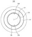
도 1은 본 발명의 일 실시예에 따른 음료용기의 사시도.
도 2는 도 1에 도시된 음료용기의 분해 사시도.
도 3의 (a) 및 (b)는 도 1에 도시된 음료용기에 포함되는 내부마개의 측면도 및 저면도.
도 4의 (a) 및 (b)는 도 1에 도시된 음료용기에 포함되는 외부마개의 측면도 및 저면도.
도 5는 도 1에 도시된 음료용기에 포함되는 외부마개의 사시도.
도 6은 도 5에 도시된 외부마개의 평면도.
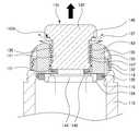
도 7은 도 1에 도시된 음료용기의 내부마개가 닫혀서 추출구가 폐쇄된 상태의 A-A'선에 따른 단면도.
도 8은 도 7에 도시된 음료용기의 내부마개가 열려서 추출구가 개방된 상태의 단면도.1 is a perspective view of a beverage container according to an embodiment of the present invention;
Fig. 2 is an exploded perspective view of the beverage container shown in Fig. 1; Fig.
3 (a) and 3 (b) are a side view and a bottom view of an inner stopper included in the beverage container shown in Fig. 1;
4 (a) and 4 (b) are a side view and a bottom view of an outer stopper included in the beverage container shown in Fig. 1;
FIG. 5 is a perspective view of an outer stopper included in the beverage container shown in FIG. 1; FIG.
6 is a plan view of the outer stopper shown in Fig.
7 is a cross-sectional view taken along the line A-A 'in a state where the inner stopper of the beverage container shown in FIG. 1 is closed and the extraction port is closed;
FIG. 8 is a sectional view of the beverage container shown in FIG. 7 with the inner stopper opened and the extraction port opened. FIG.
본 명세서에서 사용한 용어는 단지 특정한 실시예를 설명하기 위해 사용된 것으로, 본 발명을 한정하려는 의도가 아니다. 또한, 본 명세서에서 단수의 표현은 문맥상 명백하게 다르게 뜻하지 않는 한, 복수의 표현을 포함한다.
The terminology used herein is for the purpose of describing particular embodiments only and is not intended to be limiting of the invention. Furthermore, the singular forms "a", "an," and "the" include plural referents unless the context clearly dictates otherwise.
이하, 첨부한 도면을 참고로 하여 본 발명의 바람직한 실시예에 대하여 설명한다.Hereinafter, preferred embodiments of the present invention will be described with reference to the accompanying drawings.
도 1 내지 도 8을 참조하여, 본 발명의 일 실시예에 따른 음료용기에 대해서 살펴본다.1 to 8, a beverage container according to an embodiment of the present invention will be described.
도 1 내지 도 8에 도시된 바와 같이, 본 발명의 일 실시예에 따른 음료용기(100)는 용기본체(110), 캡부재(120), 외부마개(130), 내부마개(140), 제1 스테인리스부(134), 제2 스테인리스부(144), 외부 실링부(135), 제1 내부 실링부(145), 제2 내부 실링부(146), 외부추출유로(136)부, 내부추출유로(147)부 및 추출가이드부(137)를 포함할 수 있다.
1 to 8, a
상기 용기본체(110)는 상단에 개구부(112)를 구비하며, 내부에 음료가 저장될 수 있는 공간을 구비할 수 있다.The
일 실시예에서, 용기본체(110)는 원통형태로 구성될 수 있으나, 이에 한정되는 것은 아니다.In one embodiment, the
또한, 일 실시예에서, 용기본체(110)는 내면이 스테인리스 재질로 이루어지고 보온성능을 가지는 재질 및 구조로 구성될 수 있으나, 이에 한정되는 것은 아니다.In an embodiment, the inner surface of the
또한, 일 실시예에서, 개구부(112)의 내주면에는 후술할 외부마개(130)의 외측나사산(132)에 나사결합되는 체결나사산(114)이 형성될 수 있다.Also, in one embodiment, a
또한, 일 실시예에서, 용기본체(110)의 내면에는 후술할 외부마개(130)에 구비되는 외부 실링부(135)가 수밀하게 밀착되는 단턱부(116)가 형성될 수 있다.
In an embodiment, the inner surface of the
상기 캡부재(120)는 도 1, 도 2 및 도 7에 도시된 바와 같이 후술할 외부마개(130) 및 내부마개(140)를 덮도록 용기본체(110)의 상단에 체결될 수 있다.The
이러한 캡부재(120)는 용기본체(110)에서 분리하여 컵으로 사용될 수도 있다.
The
상기 외부마개(130)는 용기본체(110)의 개구부(112)에 체결가능하며, 외부마개(130)가 용기본체(110)에 체결되는 경우에 용기본체(110)의 개구부(112)와 소통될 수 있는 추출구(131)를 구비할 수 있다.The
상기 추출구(131)는 용기본체(110)의 몸체를 관통하여 형성되는 중공형태의 구멍으로 형성될 수 있다.The
일 실시예에서, 외부마개(130)는 외측나사산(132)과 내측나사산(133)을 구비할 수 있다.In one embodiment,
상기 외측나사산(132)은 외부마개(130)의 외주면에 형성되어 상기 체결나사산(114)에 나사결합될 수 있다.The
그리고, 상기 내측나사산(133)은 외부마개(130)의 내주면에 형성되어 후술할 내부마개(140)에 형성된 개폐나사산(143)에 나사결합될 수 있다.
The
상기 내부마개(140)는 추출구(131)에 삽입되고, 외부마개(130)의 높이방향으로 이동하면서 추출구(131)를 개폐할 수 있다. 즉, 내부마개(140)는 외부마개(130)에 체결된 상태에서 외부마개(130)의 상방으로 이동되어 추출구(131)를 개방시킬 수 있고, 외부마개(130)의 하방으로 이동되어 추출구(131)를 폐쇄시킬 수 있다.The
이를 위해, 일 실시예에서, 내부마개(140)는 삽입부(141)와 손잡이부(142)를 포함할 수 있다.To this end, in one embodiment, the
상기 삽입부(141)는 추출구(131)에 삽입될 수 있는 원기둥 형태의 부분이다.The
일 실시예에서, 삽입부(141)의 외주면에는 상기 내측나사산(133)에 나사결합될 수 있는 개폐나사산(143)이 형성될 수 있다.In one embodiment, an opening /
상기 손잡이부(142)는 삽입부(141)의 상단에 구비되며, 추출구(131)를 통과하지 못하는 형태로 구성될 수 있다.The
일 실시예에서, 손잡이부(142)는 삽입부(141)의 상단이 삽입부(141)의 반경방향으로 수평하게 확장되어 형성될 수 있다.In one embodiment, the
일 예로, 손잡이부(142)는 추출구(131)의 직경보다 넓은 직경의 원기둥 형태의 블록으로 구성될 수 있으나, 이에 한정되는 것은 아니다.For example, the
이러한 구조를 통해, 삽입부(141)와 손잡이부(142)가 이어지는 경계부위는 직각형태로 형성될 수 있다.Through such a structure, the boundary portion between the
한편, 사용자는 손잡이부(142)를 잡고 내부마개(140)를 회전시킴으로써, 외부마개(130)에 나사결합된 삽입부(141)를 회전시킬 수 있다.Meanwhile, the user can rotate the
일 실시예에서, 손잡이부(142)의 테두리는 사용자의 손에 높은 마찰력을 부여할 수 있도록 실리콘 재질로 이루어질 수 있으나, 이에 한정되는 것은 아니다.
In one embodiment, the rim of the
상기 제1 스테인리스부(134)는 외부마개(130)의 저면에 구비되며, 스테인리스 재질로 이루어질 수 있다.The first
참고로, 스테인리스 재질은 내부식성 및 내열성이 강하고 오염이 되지 않으며 중금속이나 유해물질이 발생하지 않는 특성이 있다.For reference, stainless steel materials are resistant to corrosion and heat, do not contaminate, and have no heavy metal or harmful substances.
이러한 제1 스테인리스부(134)는 외부마개(130)가 닫힌 경우 즉, 외부마개(130)가 용기본체(110)에 장착된 경우에 용기본체(110)의 내부에 배치된다.The first
상기 제2 스테인리스부(144)는 내부마개(140)의 저면에 구비되며, 스테인리스 재질로 이루어질 수 있다.The second
이러한 제2 스테인리스부(144)는 내부마개(140)가 닫힌 경우 즉, 내부마개(140)가 외부마개(130)에 장착된 경우에 용기본체(110)의 내부에 배치될 수 있다.The second
이와 같이 제1 스테인리스부(134)와 제2 스테인리스부(144)를 포함하는 본 발명의 일 실시예에 따른 음료용기(100)는 용기본체(110)의 내부에 저장된 음료에 노출되고 음료에 접하는 부분이 스테인리스 재질로 이루어지므로, 외부마개(130) 및 내부마개(140)의 내부식성이 향상되며 음료를 위생적으로 보관할 수 있다는 장점이 있다.
The
상기 외부 실링부(135)는 외부마개(130)의 저부에 구비되며, 제1 스테인리스부(134)의 둘레를 둘러싸는 링 형태로 구성될 수 있다.The
이러한 외부 실링부(135)는 외부마개(130)가 용기본체(110)에 장착되는 경우에 용기본체(110)의 내벽에 형성된 상기 단턱부(116)에 밀착되어, 외부마개(130)와 용기본체(110) 사이를 수밀하게 실링할 수 있다.The
일 예로, 외부 실링부(135)는 실리콘으로 이루어질 수 있으나, 이에 한정되는 것은 아니다.
For example, the
상기 제1 내부 실링부(145)는 내부마개(140)의 저부에 구비되며, 제2 스테인리스부(144)의 둘레를 둘러싸는 링 형태로 구성될 수 있다.The first
이러한 제1 내부 실링부(145)는 내부마개(140)가 외부마개(130)에 장착되어 추출구(131)를 폐쇄하는 경우에 제1 스테인리스부(134)에 밀착되어, 내부마개(140)와 외부마개(130) 사이를 수밀하게 실링할 수 있다.The first
일 예로, 제1 내부 실링부(145)는 실리콘으로 이루어질 수 있으나, 이에 한정되는 것은 아니다.
For example, the first
상기 제2 내부 실링부(146)는 손잡이부(142)와 삽입부(141)의 경계 즉, 후술할 확장면(147a)에 구비되는 링 형태로 구성될 수 있다.The second inner sealing
이러한 제2 내부 실링부(146)는 내부마개(140)가 외부마개(130)에 장착되어 내부마개(140)가 닫힌 경우에 외부마개(130)의 상단에 접하여 추출구(131)를 밀폐할 수 있다.When the
일 예로, 제2 내부 실링부(146)는 실리콘으로 이루어질 수 있으나, 이에 한정되는 것은 아니다.For example, the second inner sealing
또한, 일 실시예에서, 제2 내부 실링부(146)는 상하면이 평평한 환형으로 구성될 수 있다.Further, in one embodiment, the second inner sealing
이와 같은 구성을 가지는 본 발명의 일 실시예에 따른 음료용기(100)는 내부마개(140)가 닫힌 경우에, 용기본체(110)의 내부가 제1 내부 실링부(145)를 통해 1차적으로 밀폐되고, 제2 내부 실링부(146)를 통해 2차적으로 밀폐되는 2중 밀폐구조를 가지므로, 음료의 유출 방지 성능이 뛰어나고 보온성이 높다는 장점을 가진다.The
한편, 내부마개(140)를 열고 용기본체(110)에 저장된 음료를 따르는 경우에 추출구(131)를 통해 유출되는 음료는 제2 내부 실링부(146)를 타고 유동하여 외부로 추출될 수 있다.
On the other hand, when the
상기 외부추출유로(136)는 외부마개(130)의 내주면에 형성되어 추출구(131)에서 추출되는 유체가 유동하는 경로를 구성할 수 있다.The
다시 말해, 외부추출유로(136)는 내부마개(140)와 외부마개(130)의 사이에 형성되는 홈 형태로 이루어져서 추출구(131)를 통해 추출되는 음료를 가이드할 수 있다.In other words, the
일 실시예에서, 외부추출유로(136)는 도 5 내지 도 8에 도시된 바와 같이 내측나사산의 일부분이 외부마개(130)의 높이방향으로 길게 배제되어 형성될 수 있다.5 to 8, the
외부추출유로(136)는 내측나사산이 배제된 형태로 형성되므로, 유체가 원활하게 유동할 수 있도록 표면이 매끄럽게 형성될 수 있다.Since the
일 실시예에서, 외부추출유로(136)는 후술할 내부추출유로(147)가 삽입부(141)의 양측에 형성되는 구조에 대응하여 외부마개(130)의 내주면에서 서로 대향하는 위치에 2개소가 형성될 수도 있으나, 이에 한정되는 것은 아니다.The outer
이러한 외부추출유로(136)는 음료가 유동하는 독립적인 유로를 형성할 수도 있고, 후술할 내부추출유로(147)와 합형되어 즉, 내부추출유로(147)와 대향하도록 배치되어 더 넓은 면적의 유로를 형성할 수도 있다.The external
도시하지는 않았지만, 외부마개(130)의 상단 또는 측면에는 외부에서 외부추출유로(136)의 위치를 육안으로 확인할 수 있는 표시가 구비될 수도 있다.
Although not shown, the upper end or the side surface of the
상기 내부추출유로(147)는 내부마개(140)의 외주면에 형성되어 추출구(131)에서 추출되는 유체가 유동하는 경로를 구성할 수 있다.The
일 실시예에서, 내부추출유로(147)는 도 2, 도 3, 도 7 및 도 8에 도시된 바와 같이 내부마개(140)의 삽입부(141)의 외주면에 오목하고 높이방향으로 길게 연장된 홈 형태로 형성될 수 있다.2, 3, 7, and 8, the
또한, 일 실시예에서, 내부추출유로(147)는 삽입부(141)의 양측에 형성될 수 있다.Further, in one embodiment, the
이러한 내부추출유로(147)는 음료가 유동하는 독립적인 유로를 형성할 수도 있고, 상기 외부추출유로(136)와 합형되어 즉, 외부추출유로(136)와 대향하도록 배치되어 더 넓은 면적의 유로를 형성할 수도 있다.The
도시하지는 않았지만, 내부마개(140)의 상단 또는 측면에는 외부에서 내부추출유로(147)의 위치를 육안으로 확인할 수 있는 표시가 구비될 수도 있다.Although not shown, the upper end or the side surface of the
즉, 내부마개(140)의 외면에 내부추출유로(147)의 위치에 대응되는 표시가 구비될 수 있다.In other words, an indication corresponding to the position of the
이러한 표시를 보고, 사용자는 내부추출유로(147)와 외부추출유로(136)를 용이하게 일치시킬 수 있다.By viewing such a display, the user can easily match the
한편, 전술한 바와 같이, 손잡이부(142)가 삽입부(141)의 상단에서 반경방향으로 수평하게 확장되어 형성되는 구조로 인해, 내부추출유로(147)의 상부에는 수평방향으로 연장된 확장면(147a)이 형성될 수 있다.
As described above, due to the structure in which the
상기 추출가이드부(137)는 추출구(131)의 상단이 반경방향으로 경사지게 확장되도록 외부마개(130)의 상단에 형성될 수 있다.The
일 실시예에서, 추출가이드부(137)는 도 2, 도 4, 도 5, 도 7 및 도 8에 도시된 바와 같이 외부마개(130)의 상단에 깔때기 형상으로 돌출 형성될 수 있으나, 이에 한정되는 것은 아니며, 외부마개(130)의 상단에서 돌출되지 않고 추출구(131)의 상단 일부가 경사지게 깎인 형태로 형성될 수도 있다.In one embodiment, the
이와 같은 추출가이드부(137)는 추출구(131)를 통해 추출되는 유체가 표면장력으로 인해 외부마개(130)의 표면을 따라 흐르지 않고 원활하게 따라질 수 있도록 유체를 안내할 수 있다.The
또한, 추출가이드부(137)는 추출구(131)의 상단을 확관된 형태로 형성하므로, 추출구(131)를 통해 유체를 용기본체(110)로 주입하는 작업의 편리성을 향상시킬 수 있다.
Since the
본 발명은 특정한 실시예에 관하여 도시하고 설명하였지만, 당업계에서 통상의 지식을 가진 자라면 이하의 특허청구범위에 기재된 본 발명의 사상 및 영역을 벗어나지 않는 범위 내에서 본 발명을 다양하게 수정 및 변경시킬 수 있음을 밝혀두고자 한다.While the present invention has been particularly shown and described with reference to particular embodiments thereof, it is evident that many alternatives, modifications and variations will be apparent to those skilled in the art without departing from the spirit and scope of the invention as defined by the following claims I would like to make it clear.
100: 음료용기110: 용기본체
112: 개구부114: 체결나사산
116: 단턱부120: 캡부재
130: 외부마개131: 추출구
132: 외측나사산133: 내측나사산
134: 제1 스테인리스부135: 외부 실링부
136: 외부추출유로137: 추출가이드부
140: 내부마개141: 삽입부
142: 손잡이부142a: 확장면
143: 개폐나사산144: 제2 스테인리스부
145: 제1 내부 실링부146: 제2 내부 실링부
147: 내부추출유로100: beverage container 110: container body
112: opening 114: fastening thread
116: step portion 120: cap member
130: outer stopper 131:
132: outer thread 133: inner thread
134: first stainless steel part 135: outer sealing part
136: External extraction channel 137: Extraction guide section
140: inner stopper 141:
142: Handle
143: Closed screw thread 144: Second stainless steel part
145: first inner sealing portion 146: second inner sealing portion
147: Internal extraction channel
Claims (7)
Translated fromKorean상기 개구부에 체결가능하며, 상기 개구부와 소통되는 추출구를 구비하는 외부마개;
상기 추출구에 나사결합되는 삽입부와, 상기 삽입부의 상단에 형성되는 손잡이부를 포함하는 내부마개; 및
상기 삽입부의 외주면에 오목한 홈 형태로 형성되며, 상기 추출구에서 추출되는 유체가 유동하는 경로를 구성하는 내부추출유로;를 포함하고,
상기 손잡이부는 상기 삽입부의 상단이 상기 삽입부의 반경방향으로 수평하게 확장되어 형성되고,
상기 내부추출유로의 상부에는 수평방향으로 연장된 확장면이 형성된 음료용기로,
상기 음료 용기는,
상기 외부마개가 닫힌 경우에 상기 용기본체의 내부에 배치되도록 상기 외부마개의 저면에 구비되는 스테인리스(Stainless) 재질로 이루어진 제1 스테인리스부; 및
상기 내부마개가 닫힌 경우에 상기 용기본체의 내부에 배치되도록 상기 내부마개의 저면에 구비되는 스테인리스 재질로 이루어진 제2 스테인리스부;를 더 포함하는 음료용기.
A container body having an opening at an upper end thereof;
An outer cap which is fastened to the opening and has an extraction port communicating with the opening;
An inner cap having an insertion portion screwed into the extraction port and a handle formed at an upper end of the insertion portion; And
And an inner extraction channel formed in a concave groove shape on an outer circumferential surface of the insertion section and constituting a path through which the fluid extracted from the extraction port flows,
Wherein the grip portion is formed by horizontally extending the upper end of the insertion portion in the radial direction of the insertion portion,
A beverage container in which an enlarged surface extending in a horizontal direction is formed on an upper portion of the inner extraction channel,
The beverage container includes:
A first stainless steel part formed of a stainless steel material provided on a bottom surface of the outer cap to be disposed inside the container body when the outer cap is closed; And
And a second stainless steel part made of a stainless steel material provided on a bottom surface of the inner stopper so as to be disposed inside the container main body when the inner stopper is closed.
상기 외부마개의 저부에 상기 제1 스테인리스부의 둘레를 둘러싸도록 구비되는 외부 실링부; 및
상기 내부마개의 저부에 상기 제2 스테인리스부의 둘레를 둘러싸도록 구비되는 제1 내부 실링부;를 포함하는 음료용기.
The method according to claim 1,
An outer sealing portion provided at a bottom portion of the outer stopper to surround the periphery of the first stainless steel portion; And
And a first inner sealing portion provided at a bottom portion of the inner stopper to surround the periphery of the second stainless steel portion.
상기 확장면에 구비되며, 상기 내부마개가 닫힌 경우에 상기 외부마개의 상단에 접하여 상기 추출구를 밀폐하는 제2 내부 실링부를 포함하는 음료용기.
The method according to claim 1,
And a second internal sealing portion provided on the enlarged surface and contacting the upper end of the outer stopper to seal the extraction port when the inner stopper is closed.
상기 외부마개의 내주면에 형성되어 상기 추출구에서 추출되는 유체가 유동하는 경로를 구성하는 외부추출유로부를 포함하는 음료용기.
The method according to claim 1,
And an outer extraction channel portion formed on an inner circumferential surface of the outer stopper and constituting a path through which the fluid extracted from the extraction port flows.
상기 외부마개의 내주면에는 내측나사산이 형성되고,
상기 내부마개에는 상기 내측나사산에 나사결합되는 개폐나사산이 형성되며,
상기 외부추출유로부는 상기 내측나사산의 일부분이 배제되어 형성된 음료용기.
6. The method of claim 5,
An inner thread is formed on the inner peripheral surface of the outer stopper,
Wherein the inner stopper is formed with an opening / closing thread threadably engaged with the inner thread,
Wherein the outer extraction channel portion is formed by excluding a portion of the inner thread.
상기 외부마개는 상기 추출구의 상단이 반경방향으로 경사지게 확장되도록 상기 외부마개의 상단에 형성되는 추출가이드부를 구비하는 음료용기.The method according to claim 1,
Wherein the outer stopper includes an extraction guide formed at an upper end of the outer stopper so that an upper end of the extraction stop extends in a radial direction.
Priority Applications (1)
| Application Number | Priority Date | Filing Date | Title |
|---|---|---|---|
| KR1020150063933AKR101668309B1 (en) | 2015-05-07 | 2015-05-07 | Drink container |
Applications Claiming Priority (1)
| Application Number | Priority Date | Filing Date | Title |
|---|---|---|---|
| KR1020150063933AKR101668309B1 (en) | 2015-05-07 | 2015-05-07 | Drink container |
Publications (1)
| Publication Number | Publication Date |
|---|---|
| KR101668309B1true KR101668309B1 (en) | 2016-10-26 |
Family
ID=57251675
Family Applications (1)
| Application Number | Title | Priority Date | Filing Date |
|---|---|---|---|
| KR1020150063933AActiveKR101668309B1 (en) | 2015-05-07 | 2015-05-07 | Drink container |
Country Status (1)
| Country | Link |
|---|---|
| KR (1) | KR101668309B1 (en) |
Cited By (18)
| Publication number | Priority date | Publication date | Assignee | Title |
|---|---|---|---|---|
| KR101774177B1 (en)* | 2016-12-12 | 2017-09-01 | 김학래 | Liquid Container Having Double Cap |
| KR101774176B1 (en)* | 2016-12-12 | 2017-09-01 | 김학래 | Liquid Container Having Double Cap |
| KR101774175B1 (en)* | 2016-12-12 | 2017-09-01 | 김학래 | Liquid Container Having Single Cap |
| CN107989399A (en)* | 2017-12-20 | 2018-05-04 | 佛山科学技术学院 | A kind of intelligent concrete prosthetic device |
| USD860716S1 (en) | 2017-03-27 | 2019-09-24 | Yeti Coolers, Llc | Container lid |
| USD871133S1 (en) | 2018-10-17 | 2019-12-31 | Yeti Coolers, Llc | Lid |
| USD883737S1 (en) | 2018-10-17 | 2020-05-12 | Yeti Coolers, Llc | Lid |
| USD883738S1 (en) | 2018-10-17 | 2020-05-12 | Yeti Coolers, Llc | Lid |
| USD896572S1 (en) | 2018-08-20 | 2020-09-22 | Yeti Coolers, Llc | Container lid |
| USD897151S1 (en) | 2018-10-17 | 2020-09-29 | Yeti Coolers, Llc | Lid |
| US10926925B2 (en) | 2015-08-14 | 2021-02-23 | Yeti Coolers, Llc | Container with magnetic cap |
| US10959553B2 (en) | 2016-10-17 | 2021-03-30 | Yeti Coolers, Llc | Container and method of forming a container |
| US10959552B2 (en) | 2016-10-17 | 2021-03-30 | Yeti Coolers, Llc | Container and method of forming a container |
| US11021314B2 (en) | 2016-10-17 | 2021-06-01 | Yeti Coolers, Llc | Container and method of forming a container |
| US11034505B2 (en) | 2016-10-17 | 2021-06-15 | Yeti Coolers, Llc | Container and method of forming a container |
| USD960660S1 (en) | 2015-11-20 | 2022-08-16 | Yeti Coolers, Llc | Jug |
| CN115959372A (en)* | 2021-10-13 | 2023-04-14 | 膳魔师(中国)家庭制品有限公司 | Cap unit and container with cap |
| CN115959355A (en)* | 2021-10-13 | 2023-04-14 | 膳魔师(中国)家庭制品有限公司 | Cap units and capped containers |
Citations (1)
| Publication number | Priority date | Publication date | Assignee | Title |
|---|---|---|---|---|
| KR19980024183A (en)* | 1996-09-03 | 1998-07-06 | 츠치야 히로오 | Stopper |
- 2015
- 2015-05-07KRKR1020150063933Apatent/KR101668309B1/enactiveActive
Patent Citations (1)
| Publication number | Priority date | Publication date | Assignee | Title |
|---|---|---|---|---|
| KR19980024183A (en)* | 1996-09-03 | 1998-07-06 | 츠치야 히로오 | Stopper |
Cited By (37)
| Publication number | Priority date | Publication date | Assignee | Title |
|---|---|---|---|---|
| US10926925B2 (en) | 2015-08-14 | 2021-02-23 | Yeti Coolers, Llc | Container with magnetic cap |
| US12227340B2 (en) | 2015-08-14 | 2025-02-18 | Yeti Coolers, Llc | Container with magnetic cap |
| US11794960B2 (en) | 2015-08-14 | 2023-10-24 | Yeti Coolers, Llc | Container with magnetic cap |
| US11273961B2 (en) | 2015-08-14 | 2022-03-15 | Yeti Coolers, Llc | Container with magnetic cap |
| USD1039919S1 (en) | 2015-11-20 | 2024-08-27 | Yeti Coolers, Llc | Jug |
| USD1018214S1 (en) | 2015-11-20 | 2024-03-19 | Yeti Coolers, Llc | Jug |
| USD960660S1 (en) | 2015-11-20 | 2022-08-16 | Yeti Coolers, Llc | Jug |
| US11034505B2 (en) | 2016-10-17 | 2021-06-15 | Yeti Coolers, Llc | Container and method of forming a container |
| US11503932B2 (en) | 2016-10-17 | 2022-11-22 | Yeti Coolers, Llc | Container and method of forming a container |
| US12269666B2 (en) | 2016-10-17 | 2025-04-08 | Yeti Coolers, Llc | Container and method of forming a container |
| US11930944B2 (en) | 2016-10-17 | 2024-03-19 | Yeti Coolers, Llc | Container and method of forming a container |
| US11840365B2 (en) | 2016-10-17 | 2023-12-12 | Yeti Coolers, Llc | Container and method of forming a container |
| US11814235B2 (en) | 2016-10-17 | 2023-11-14 | Yeti Coolers, Llc | Container and method of forming a container |
| US11524833B2 (en) | 2016-10-17 | 2022-12-13 | Yeti Coolers, Llc | Container and method of forming a container |
| US11021314B2 (en) | 2016-10-17 | 2021-06-01 | Yeti Coolers, Llc | Container and method of forming a container |
| US10959553B2 (en) | 2016-10-17 | 2021-03-30 | Yeti Coolers, Llc | Container and method of forming a container |
| US10959552B2 (en) | 2016-10-17 | 2021-03-30 | Yeti Coolers, Llc | Container and method of forming a container |
| KR101774175B1 (en)* | 2016-12-12 | 2017-09-01 | 김학래 | Liquid Container Having Single Cap |
| KR101774177B1 (en)* | 2016-12-12 | 2017-09-01 | 김학래 | Liquid Container Having Double Cap |
| KR101774176B1 (en)* | 2016-12-12 | 2017-09-01 | 김학래 | Liquid Container Having Double Cap |
| US10414556B2 (en) | 2016-12-12 | 2019-09-17 | Hak Rae KIM | Liquid container having single cap |
| US10414558B2 (en) | 2016-12-12 | 2019-09-17 | Hak Rae KIM | Liquid container having double cap |
| USD860716S1 (en) | 2017-03-27 | 2019-09-24 | Yeti Coolers, Llc | Container lid |
| CN107989399A (en)* | 2017-12-20 | 2018-05-04 | 佛山科学技术学院 | A kind of intelligent concrete prosthetic device |
| USD896572S1 (en) | 2018-08-20 | 2020-09-22 | Yeti Coolers, Llc | Container lid |
| USD988789S1 (en) | 2018-08-20 | 2023-06-13 | Yeti Coolers, Llc | Container lid |
| USD913746S1 (en) | 2018-08-20 | 2021-03-23 | Yeti Coolers, Llc | Container lid |
| USD1061140S1 (en) | 2018-08-20 | 2025-02-11 | Yeti Coolers, Llc | Container lid |
| USD913745S1 (en) | 2018-08-20 | 2021-03-23 | Yeti Coolers, Llc | Container lid |
| USD1046619S1 (en) | 2018-10-17 | 2024-10-15 | Yeti Coolers, Llc | Lid |
| USD883737S1 (en) | 2018-10-17 | 2020-05-12 | Yeti Coolers, Llc | Lid |
| USD871133S1 (en) | 2018-10-17 | 2019-12-31 | Yeti Coolers, Llc | Lid |
| USD897151S1 (en) | 2018-10-17 | 2020-09-29 | Yeti Coolers, Llc | Lid |
| USD935268S1 (en) | 2018-10-17 | 2021-11-09 | Yeti Coolers, Llc | Lid |
| USD883738S1 (en) | 2018-10-17 | 2020-05-12 | Yeti Coolers, Llc | Lid |
| CN115959355A (en)* | 2021-10-13 | 2023-04-14 | 膳魔师(中国)家庭制品有限公司 | Cap units and capped containers |
| CN115959372A (en)* | 2021-10-13 | 2023-04-14 | 膳魔师(中国)家庭制品有限公司 | Cap unit and container with cap |
Similar Documents
| Publication | Publication Date | Title |
|---|---|---|
| KR101668309B1 (en) | Drink container | |
| US10669081B2 (en) | Lid for container | |
| US9988202B2 (en) | Retaining member and insulating vessel incorporating same | |
| KR101774176B1 (en) | Liquid Container Having Double Cap | |
| JP5627732B2 (en) | Beverage container closure | |
| KR100807212B1 (en) | Anti-lost container with connection member | |
| KR20170043856A (en) | Drink container | |
| CA3025507A1 (en) | Lid for a beverage container | |
| US9919849B2 (en) | Closure for a beverage cup | |
| US20110186573A1 (en) | Cap for a container | |
| US20170050776A1 (en) | Lid for container with rotatable reclosable spout | |
| US20180265265A1 (en) | Beverage container lid | |
| WO2006097640A8 (en) | Closing device with integrated rotary closure for feeding bottle and bottle | |
| JP2013184738A (en) | Tumbler | |
| JP2013184741A (en) | Cap | |
| JP2021187450A (en) | Cap unit and container with cap unit | |
| WO2015143921A1 (en) | Cup cover assembly | |
| KR200457587Y1 (en) | Bottle cap capable of opening and shutting straw-insert hole | |
| TW202321124A (en) | Lid assembly and container with lid | |
| RU137906U1 (en) | UNIVERSAL SCREW COVER FOR SEALING CONSTRUCTIVELY DIFFERENT BOTTLING OPENINGS OF BOTTLES WITH LIQUID | |
| KR101774177B1 (en) | Liquid Container Having Double Cap | |
| TWM492883U (en) | Pulling type beverage bottle cap assembly | |
| TWM528977U (en) | Separate type self-making beverage device | |
| CA2692059A1 (en) | Cap for a container | |
| KR200478362Y1 (en) | A cap for package bottle |
Legal Events
| Date | Code | Title | Description |
|---|---|---|---|
| PA0109 | Patent application | Patent event code:PA01091R01D Comment text:Patent Application Patent event date:20150507 | |
| PA0201 | Request for examination | ||
| PE0902 | Notice of grounds for rejection | Comment text:Notification of reason for refusal Patent event date:20160517 Patent event code:PE09021S01D | |
| E701 | Decision to grant or registration of patent right | ||
| PE0701 | Decision of registration | Patent event code:PE07011S01D Comment text:Decision to Grant Registration Patent event date:20160929 | |
| GRNT | Written decision to grant | ||
| PR0701 | Registration of establishment | Comment text:Registration of Establishment Patent event date:20161017 Patent event code:PR07011E01D | |
| PR1002 | Payment of registration fee | Payment date:20161017 End annual number:3 Start annual number:1 | |
| PG1601 | Publication of registration | ||
| FPAY | Annual fee payment | Payment date:20190917 Year of fee payment:4 | |
| PR1001 | Payment of annual fee | Payment date:20190917 Start annual number:4 End annual number:4 | |
| PR1001 | Payment of annual fee | Payment date:20200923 Start annual number:5 End annual number:5 | |
| PR1001 | Payment of annual fee | Payment date:20211015 Start annual number:6 End annual number:6 | |
| PR1001 | Payment of annual fee | Payment date:20221226 Start annual number:7 End annual number:7 | |
| PR1001 | Payment of annual fee | Payment date:20240117 Start annual number:8 End annual number:8 | |
| PR1001 | Payment of annual fee | Payment date:20241002 Start annual number:9 End annual number:9 |