KR101666561B1 - System and Method for obtaining Subspace in Augmented Space - Google Patents
System and Method for obtaining Subspace in Augmented SpaceDownload PDFInfo
- Publication number
- KR101666561B1 KR101666561B1KR1020150099124AKR20150099124AKR101666561B1KR 101666561 B1KR101666561 B1KR 101666561B1KR 1020150099124 AKR1020150099124 AKR 1020150099124AKR 20150099124 AKR20150099124 AKR 20150099124AKR 101666561 B1KR101666561 B1KR 101666561B1
- Authority
- KR
- South Korea
- Prior art keywords
- subspace
- unit
- user
- space
- tunnel
- Prior art date
- Legal status (The legal status is an assumption and is not a legal conclusion. Google has not performed a legal analysis and makes no representation as to the accuracy of the status listed.)
- Active
Links
Images


Classifications
- G—PHYSICS
- G06—COMPUTING OR CALCULATING; COUNTING
- G06F—ELECTRIC DIGITAL DATA PROCESSING
- G06F3/00—Input arrangements for transferring data to be processed into a form capable of being handled by the computer; Output arrangements for transferring data from processing unit to output unit, e.g. interface arrangements
- G06F3/01—Input arrangements or combined input and output arrangements for interaction between user and computer
- G06F3/048—Interaction techniques based on graphical user interfaces [GUI]
- G06F3/0481—Interaction techniques based on graphical user interfaces [GUI] based on specific properties of the displayed interaction object or a metaphor-based environment, e.g. interaction with desktop elements like windows or icons, or assisted by a cursor's changing behaviour or appearance
- G06F3/04815—Interaction with a metaphor-based environment or interaction object displayed as three-dimensional, e.g. changing the user viewpoint with respect to the environment or object
- G—PHYSICS
- G06—COMPUTING OR CALCULATING; COUNTING
- G06F—ELECTRIC DIGITAL DATA PROCESSING
- G06F3/00—Input arrangements for transferring data to be processed into a form capable of being handled by the computer; Output arrangements for transferring data from processing unit to output unit, e.g. interface arrangements
- G06F3/01—Input arrangements or combined input and output arrangements for interaction between user and computer
- G06F3/011—Arrangements for interaction with the human body, e.g. for user immersion in virtual reality
- G06F3/012—Head tracking input arrangements
- G—PHYSICS
- G06—COMPUTING OR CALCULATING; COUNTING
- G06F—ELECTRIC DIGITAL DATA PROCESSING
- G06F3/00—Input arrangements for transferring data to be processed into a form capable of being handled by the computer; Output arrangements for transferring data from processing unit to output unit, e.g. interface arrangements
- G06F3/01—Input arrangements or combined input and output arrangements for interaction between user and computer
- G06F3/011—Arrangements for interaction with the human body, e.g. for user immersion in virtual reality
- G06F3/013—Eye tracking input arrangements
- G—PHYSICS
- G06—COMPUTING OR CALCULATING; COUNTING
- G06F—ELECTRIC DIGITAL DATA PROCESSING
- G06F3/00—Input arrangements for transferring data to be processed into a form capable of being handled by the computer; Output arrangements for transferring data from processing unit to output unit, e.g. interface arrangements
- G06F3/01—Input arrangements or combined input and output arrangements for interaction between user and computer
- G06F3/017—Gesture based interaction, e.g. based on a set of recognized hand gestures
- G—PHYSICS
- G06—COMPUTING OR CALCULATING; COUNTING
- G06F—ELECTRIC DIGITAL DATA PROCESSING
- G06F3/00—Input arrangements for transferring data to be processed into a form capable of being handled by the computer; Output arrangements for transferring data from processing unit to output unit, e.g. interface arrangements
- G06F3/01—Input arrangements or combined input and output arrangements for interaction between user and computer
- G06F3/03—Arrangements for converting the position or the displacement of a member into a coded form
- G06F3/0304—Detection arrangements using opto-electronic means
- G—PHYSICS
- G06—COMPUTING OR CALCULATING; COUNTING
- G06F—ELECTRIC DIGITAL DATA PROCESSING
- G06F3/00—Input arrangements for transferring data to be processed into a form capable of being handled by the computer; Output arrangements for transferring data from processing unit to output unit, e.g. interface arrangements
- G06F3/01—Input arrangements or combined input and output arrangements for interaction between user and computer
- G06F3/03—Arrangements for converting the position or the displacement of a member into a coded form
- G06F3/041—Digitisers, e.g. for touch screens or touch pads, characterised by the transducing means
- G06F3/042—Digitisers, e.g. for touch screens or touch pads, characterised by the transducing means by opto-electronic means
- G06F3/0425—Digitisers, e.g. for touch screens or touch pads, characterised by the transducing means by opto-electronic means using a single imaging device like a video camera for tracking the absolute position of a single or a plurality of objects with respect to an imaged reference surface, e.g. video camera imaging a display or a projection screen, a table or a wall surface, on which a computer generated image is displayed or projected
- G—PHYSICS
- G06—COMPUTING OR CALCULATING; COUNTING
- G06F—ELECTRIC DIGITAL DATA PROCESSING
- G06F3/00—Input arrangements for transferring data to be processed into a form capable of being handled by the computer; Output arrangements for transferring data from processing unit to output unit, e.g. interface arrangements
- G06F3/01—Input arrangements or combined input and output arrangements for interaction between user and computer
- G06F3/048—Interaction techniques based on graphical user interfaces [GUI]
- G06F3/0484—Interaction techniques based on graphical user interfaces [GUI] for the control of specific functions or operations, e.g. selecting or manipulating an object, an image or a displayed text element, setting a parameter value or selecting a range
- G06F3/04845—Interaction techniques based on graphical user interfaces [GUI] for the control of specific functions or operations, e.g. selecting or manipulating an object, an image or a displayed text element, setting a parameter value or selecting a range for image manipulation, e.g. dragging, rotation, expansion or change of colour
- G—PHYSICS
- G06—COMPUTING OR CALCULATING; COUNTING
- G06T—IMAGE DATA PROCESSING OR GENERATION, IN GENERAL
- G06T19/00—Manipulating 3D models or images for computer graphics
- G06T19/006—Mixed reality
- G—PHYSICS
- G06—COMPUTING OR CALCULATING; COUNTING
- G06T—IMAGE DATA PROCESSING OR GENERATION, IN GENERAL
- G06T19/00—Manipulating 3D models or images for computer graphics
- G06T19/20—Editing of 3D images, e.g. changing shapes or colours, aligning objects or positioning parts
Landscapes
- Engineering & Computer Science (AREA)
- General Engineering & Computer Science (AREA)
- Theoretical Computer Science (AREA)
- Physics & Mathematics (AREA)
- General Physics & Mathematics (AREA)
- Human Computer Interaction (AREA)
- Software Systems (AREA)
- Computer Graphics (AREA)
- Computer Hardware Design (AREA)
- Multimedia (AREA)
- Architecture (AREA)
- Processing Or Creating Images (AREA)
- User Interface Of Digital Computer (AREA)
Abstract
Translated fromKoreanDescription
Translated fromKorean본 발명은 증강 공간 내 부분 공간 획득 시스템 및 방법에 관한 것으로, 보다 상세하게는 사용자 의한 이벤트가 발생되면, 상기 이벤트에 대응하는 제1 부분 공간을 획득하고, 상기 획득한 제1 부분 공간의 범위 내에서 위치와 스케일을 조절된 제2 부분 공간을 획득하는 증강 공간 내 부분 공간 획득 시스템 및 방법에 관한 것이다.The present invention relates to a system and method for acquiring a partial space in an enhanced space, and more particularly to a system and method for acquiring a partial space corresponding to the event when an event by a user is generated, And a method and system for acquiring a partial space in an augmented space.
증강현실(Augmented Reality;AR)이란 용어는 1990년대 초 미국 보잉사에서 항공기를 조립할 때 부품의 위치를 HMD(Head Mounted Display)의 화면을 통해 항공기의 적정한 위치에 실시간으로 보여주는 장치를 개발하고 이 연구를 발표한 논문에서 처음으로 증강현실(AR:Augmented Reality) 용어가 유래되었으며, 이때부터 증강현실에 대한 연구가 본격적으로 시작되었다고 볼 수 있으며, 현재 증강현실은 활발하게 연구가 진행되고 있는 분야이다.The term Augmented Reality (AR) was developed in the early 1990s by Boeing to develop a device that displays the position of components in real time on the appropriate position of the aircraft through the head mounted display (HMD) , Augmented Reality (AR) terminology has been derived for the first time in the paper, and research on the Augmented Reality has been started in earnest since then. Augmented Reality is currently being actively researched.
증강현실(Augmented Reality;AR)은 실세계 영상(또는 실사 영상) 위에 3차원 가상물체를 겹쳐 보여주는 것으로 현실에 기반을 두고 실세계 환경과 그래픽 형태의 가상현실을 실시간으로 합성하여 실세계에 대한 이해를 높여주는 기술로써, 증강현실의 목적은 실제 관찰하고 있는 사물이나 장소에 대한 부가적인 정보나 의미를 함께 제공하는 것이며, 가상현실 기술에 비하여 여러 가지 센서, 디스플레이 장치(시각, 청각, 촉각/역감 등), 그리고 어떤 현상을 (사실 혹은 허구) 상호작용과 함께 시뮬레이션할 수 있는 컴퓨터를 이용하여, 이를 재현하여 가상경험을 창출하는 기술이다.Augmented Reality (AR) is a technique that displays 3D virtual objects over real world images (or real images). It is based on reality and synthesizes real-world environment and graphical virtual reality in real- As a technology, the purpose of augmented reality is to provide additional information or meaning about the object or place actually observed, and to provide various sensors, display devices (visual, auditory, tactile / And it is a technique to reproduce a virtual experience by using a computer that can simulate a phenomenon (fact or fiction) with interaction.
3차원 물체 추적과 장면 복원을 위한 기술들은 사용자가 실제 공간에 어떤 기하학적인 변형이 가해진 3차원 가상 물체를 등록시키는 것을 허용한다.Techniques for three-dimensional object tracking and scene restoration allow the user to register a three-dimensional virtual object with some geometric transformation applied to the actual space.
증강 공간은 서비스 공급자에 의해 저작된 의미 있는 물리적 공간상에서 가상물체들을 증가시킨다(예를 들면, 박물관, 관광, 모델하우스, 인테리어, 게임 등등). 그러므로 그것의 물리적 물체들은 일반적으로 미리 견본이 만들어지고 그것들은 추적 할 수 있다. 이렇게 하여 사용자가 더 넓은 3차원 공간에서 가상과 실제의 상황의 다양한 조합에 의해서 더 자연스럽고 풍부하게 상호작용하는 것이 가능해진다. 이러한 맥락으로, 그것은 현장에서 사용자가 입고 있는 머리에 입혀진 디스플레이에 의해 특정한 순간에 집중되어진 부분적인 3차원 공간의 중요성이 증가되었다.The augmented space increases virtual objects in meaningful physical space authored by the service provider (for example, museums, tourism, model houses, interiors, games, etc.). Therefore, its physical objects are usually pre-fabricated and they can be traced. In this way, it becomes possible for the user to interact more naturally and abundantly in a wider three-dimensional space by various combinations of virtual and actual situations. In this context, it has increased the importance of the partial three-dimensional space centered at a particular moment by the on-the-head display of the wearer in the field.
웨어러블 증강 현실 상황에서 사용자를 고려하면 그 다음 자기 시점의 메타포어(egocentric metaphor), 기존의 볼륨(volumetric) 선택 기술들을 가상공간에서 직접적으로 증강공간에 적용하기 어렵다. 가장 큰 문제는 현실 물체들로부터 물리적 경계조건들이다. 어떤 장소에서 관심 물체(object of interest (OoI))를 얻기 위하여 장애물을 만나는 사용자와, 자유 변환과 함께 가상 공간 안의 사용자는 다르다. 예를 들면, 목표 물체는 사용자에 의해 손상되는 것이 가능하고, 주위 환경에 의해 방해 받을 수 있고, 직접 만지는 것에 관하여 너무 작거나 거리가 멀거나 또는 이들의 조합으로 부적절 할 수 있다.Considering the user in the wearable augmented reality situation, it is difficult to apply the egocentric metaphor and the existing volumetric selection techniques directly to the reinforcement space in the virtual space. The biggest problem is physical boundary conditions from real objects. Users who meet obstacles in order to obtain the object of interest (OoI) at a certain place are different from users in the virtual space together with free transformations. For example, the target object may be damaged by the user, may be disturbed by the surrounding environment, too small or too far from direct touching, or a combination of these may be inappropriate.
이런 것들을 해결하기 위하여 멀리 있는 목표물 선택, 간접적인 포인팅 테크닉, 은 보이는 목표(viewing target)에 대한 대안이 된다.In order to solve these problems, remote target selection, indirect pointing technique, is an alternative to the viewing target.
그러나 기존의 간적접인 접근들은 관심 물체 및 그것의 주변을 포함하는 사용자가 원하는 3D 볼륨(volume)을 정교하게 선택하는 것을 맞춰주지 못하는 문제가 있다.However, the existing temporal approach has a problem in that it does not allow the user, including the object of interest and its surroundings, to precisely select the desired 3D volume.
본 발명은 상기한 문제점을 해결하기 위해 발명된 것으로, 그 목적은 증강 공간에 관하여 맨손 핀치들을 이용하여 정교하게 3D 부분 공간을 획득할 수 있는 증강 공간 내 부분 공간 획득 시스템 및 방법을 제공하는 것을 목적으로 한다.It is an object of the present invention to provide a system and method for acquiring a partial space in an augmented space capable of finely acquiring a 3D subspace using bare hand pinches with respect to an augmented space .
또한, 본 발명의 다른 목적은 사용자 의한 이벤트가 발생되면, 상기 이벤트에 대응하는 제1 부분 공간을 획득하고, 상기 획득한 제1 부분 공간의 범위 내에서 위치와 스케일을 조절된 제2 부분 공간을 획득하는 증강 공간 내 부분 공간 획득 시스템 및 방법을 제공하는 것을 다른 목적으로 한다.It is another object of the present invention to provide a method and apparatus for acquiring a first subspace corresponding to an event when an event by a user is generated and acquiring a second subspace having a position and a scale adjusted within the obtained first subspace Another object of the present invention is to provide a partial space acquisition system and method in an augmented space.
또한, 본 발명의 또 다른 목적은 제1 부분 공간의 스케일을 고려한 직교 투영(orthogonal projection)에 의한 탑뷰를 제공하는 증강 공간 내 부분 공간 획득 시스템 및 방법을 제공하는 것을 또 다른 목적으로 한다.It is still another object of the present invention to provide a system and method for acquiring a partial space in an augmented space, which provides a top view by orthogonal projection considering a scale of a first subspace.
상기한 바와 같은 과제를 해결하기 위하여 본 발명은, 디스플레이 장치에서 표시되는 3D 이미지에서 사용자의 동작에 의한 이벤트가 발생되면, 상기 사용자의 동작에 대응하는 제1 입체형상의 제1 부분 공간을 획득하는 타겟팅(Targeting)부 및 상기 타겟팅부가 획득한 제1 부분 공간의 범위 내에서 사용자의 제스쳐에 따라 위치와 스케일이 조절되는 제2 입체형상의 제2 부분 공간을 획득하는 개선부를 포함한다.According to an aspect of the present invention, there is provided a method of generating a 3D image, the method comprising: generating a first subspace of a first stereoscopic image corresponding to an operation of a user, And an improvement unit for obtaining a second subspace of a second stereoscopic shape whose position and scale are adjusted in accordance with the gesture of the user within a range of the first subspace acquired by the targeting unit.
또한, 상기 타겟팅부는 상기 3D 이미지에서 사용자의 동작을 이벤트 발생으로 결정하는 이벤트 감지부, 상기 이벤트 감지부에서 결정된 사용자의 동작으로 형성된 2D 프레임을 3D공간으로 투영(projection)하여 터널을 형성하는 투영부, 상기 투영부에 의해 형성된 터널에 광선 그룹을 투사하여 포워드 캐스팅(forward casting) 및 백워드 캐스팅을 수행하는 터널 캐스팅 수행부 및 상기 터널 캐스팅 수행부에서 수행하여 획득된 절두체(frustum)를 변환하여 제1 입체형상의 제1 부분 공간을 획득하는 제1변환부를 포함할 수 있다.In addition, the targeting unit may include an event sensing unit for determining a user's operation as an event occurrence in the 3D image, a projection unit for projecting a 2D frame formed by the user's action determined by the event sensing unit into a 3D space, A tunnel casting performing unit for performing forward casting and backward casting by projecting a group of light beams to a tunnel formed by the projecting unit and a frustum obtained by performing the tunnel casting performing unit, 1 stereoscopic-type first partial space.
또한, 상기 개선부는 상기 타겟팅부가 획득한 제1 부분 공간의 범위 내에서 사용자의 양손 핀치 제스쳐를 통해 새로운 부분 공간을 형성하는 조절부, 상기 타겟팅부가 획득한 제1 부분 공간의 탑뷰를 제공하여 사용자의 양손 핀치 제스쳐를 통해 상기 조절부가 부분공간을 형성하는 것을 돕는 탑뷰제공부 및 상기 조절부에 의해 새롭게 형성된 부분공간을 변환하여 제2 입체형상의 제2 부분 공간을 획득하는 제2변환부를 포함할 수 있다.The improvement unit may further include an adjustment unit that forms a new partial space through the user's two-handed pinch gesture within a range of the first partial space acquired by the targeting unit, a top view of the first partial space acquired by the targeting unit, And a second converting unit for converting the subspace newly formed by the adjusting unit to obtain a second subspace of the second stereoscopic shape, .
또한, 상기 이벤트 감지부는 상기 3D 이미지에서 사용자의 양손 핀치팁 포인터에 의한 핀치/릴리즈(pinch and release) 이벤트 동작을 사용자의 동작에 의한 이벤트 발생으로 결정할 수 있다.Also, the event detection unit may determine a pinch and release event operation by the user's two-handed pinch tip pointer in the 3D image as an event occurrence by a user's action.
또한, 상기 투영부는 상기 3D 이미지에서 사용자의 양손 핀치팁 포인터에 의한 핀치/릴리즈(pinch and release) 동작으로 형성된 2D 프레임을 3D 공간으로 투영하여 터널을 형성할 수 있다.In addition, the projection unit may form a tunnel by projecting a 2D frame formed by a pinch and release operation by the user's two-handed pinch tip pointer into the 3D space in the 3D image.
또한, 상기 터널 캐스팅 수행부는 사용자의 눈으로부터 투사된 광선 그룹이 상기 터널에 존재하는 증강 객체들과 최초로 충돌하는 눈으로부터 가장 가까운 최초 충돌 지점을 찾는 포워드 캐스팅 및 상기 포워드 캐스팅과 동일한 광선 그룹을 반대 방향으로부터 투사하여 상기 터널에 존재하는 증강 객체들과 최초로 충돌하는 눈으로부터 가장 먼 최초 충돌 지점을 찾는 백워드 캐스팅을 수행할 수 있다.The tunnel casting unit may further include a forward casting unit that finds a first collision point closest to an eye that first collides with the augmented objects existing in the tunnel from a user's eye, To perform backward casting for finding the first collision point farthest from the first colliding eye with the augmenting objects present in the tunnel.
또한, 상기 제1변환부는 상기 눈으로부터 가장 가까운 최초 충돌 지점을 포함하는 상기 터널과 평행 슬라이스 평면인 제1평면과 상기 눈으로부터 가장 먼 최초 충돌 지점을 포함하는 상기 터널과 평행 슬라이스 평면인 제2평면으로 구성되는 절두체(frustum)의 중간을 기준으로 미리 정해진 부분 공간의 정의에 맞게 동일한 위치, 회전 및 부피를 가지는 제1 입체형상으로 변환하여 제1 부분 공간을 획득할 수 있다.The first transforming unit may include a first plane that is a parallel slice plane with the tunnel including the first collision point closest to the eye, a second plane that is a parallel slice plane with the tunnel including the first collision point farthest from the eye, To a first three-dimensional shape having the same position, rotation, and volume in accordance with the definition of the predetermined subspace based on the middle of the frustum constituted by the first subspace and the second subspace.
또한, 상기 조절부는상기 타겟팅부가 획득한 제1 부분 공간의 범위 내에서 사용자의 양손 핀치 제스쳐에 따른 상대 스케일 매핑(relative scale mapping)을 통해 직접 변경하여 새로운 부분 공간을 형성할 수 있다.In addition, the controller may directly modify the first partial space acquired by the targeting unit through a relative scale mapping according to the user's two-handed pinch gesture to form a new partial space.
또한, 상기 탑뷰제공부는 상기 타겟팅부가 획득한 제1 부분 공간의 스케일을 고려한 직교 투영(orthogonal projection)에 의한 탑뷰를 제공하여 사용자의 양손 핀치 제스쳐를 통해 상기 조절부가 부분공간을 형성하는 것을 도울 수 있다.The top view providing unit may also provide a top view by orthogonal projection that takes into account the scale of the first subspace acquired by the targeting unit to help the controlling unit form the subspace through the user's two-handed pinch gesture .
또한, 상기 제2변환부는 상기 조절부에 의해 새롭게 형성된 부분공간을 미리 정해진 부분 공간의 정의에 맞게 동일한 위치, 회전 및 부피를 가지는 제2 입체형상으로 변환하여 제2 부분 공간을 획득할 수 있다.In addition, the second conversion unit may convert the partial space newly formed by the adjustment unit into a second three-dimensional shape having the same position, rotation, and volume according to the definition of the predetermined partial space to obtain the second partial space.
또한, 상기 제1 및 제2 입체형상은 직육면체일 수 있다.Further, the first and second solid shapes may be rectangular parallelepiped.
본 발명의 다른 측면에 의하면, 이벤트 감지부가 3D 이미지에서 사용자의 동작을 이벤트 발생으로 결정하는 제1 단계, 투영부가 상기 결정된 사용자의 동작으로 형성된 2D 프레임을 3D공간으로 투영하여 터널을 형성하는 제2 단계, 터널 캐스팅 수행부가 상기 형성된 터널에 광선 그룹을 투사하여 포워드 캐스팅 및 백워드 캐스팅을 수행하는 제3 단계, 제1변환부가 상기 포워드 캐스팅 및 백워드 캐스팅을 수행하여 획득된 절두체(frustum)를 변환하여 제1 입체형상의 제1 부분 공간을 획득하는 제4 단계, 조절부가 상기 획득한 제1 부분 공간의 범위 내에서 사용자의 양손 핀치 제스쳐를 통해 새로운 부분 공간을 형성하는 제5 단계 및 제2변환부가 상기 새롭게 형성된 부분공간을 변환하여 제2 입체형상의 제2 부분 공간을 획득하는 제6 단계를 포함한다.According to another aspect of the present invention, there is provided a method for controlling an event, the method comprising: a first step of the event detection unit determining a user's action in an 3D image as an event occurrence; a second step of projecting a 2D frame formed by the determined user's operation into a 3D space, A third step of performing forward casting and backward casting by projecting a group of light beams to the tunnel formed by the tunnel casting performing unit, a first step of transforming the frustum obtained by performing the forward casting and the backward casting, A fourth step of acquiring a first subspace of the first stereoscopic shape by the first subspace, a fifth step of the regulator forming a new subspace through the user's two-handed pinch gesture within the obtained first subspace, And a sixth step of converting the newly formed subspace to obtain a second subspace of the second stereoscopic shape.
또한, 상기 제1 단계의 사용자의 동작은 양손 핀치팁 포인터에 의한 핀치/릴리즈(pinch and release) 동작일 수 있다.In addition, the operation of the user of the first stage may be a pinch and release operation by the two-handed pinch tip pointer.
본 발명에 의하면, 증강 공간에 관하여 맨손 핀치들을 이용하여 정교하게 3D 부분 공간을 획득할 수 있는 증강 공간 내 부분 공간 획득 시스템 및 방법을 제공할 수 있는 효과가 있다.According to the present invention, it is possible to provide a system and method for acquiring a partial space in an augmented space in which a 3D partial space can be finely acquired using bare hand pinches with respect to an augmented space.
또한, 사용자 의한 이벤트가 발생되면, 상기 이벤트에 대응하는 제1 부분 공간을 획득하고, 상기 획득한 제1 부분 공간의 범위 내에서 위치와 스케일을 조절된 제2 부분 공간을 획득하는 증강 공간 내 부분 공간 획득 시스템 및 방법을 제공할 수 있는 효과가 있다.In addition, when an event by a user is generated, a first subspace corresponding to the event is obtained, and a second subspace in which a position and a scale are adjusted within the obtained first subspace, There is an effect that a spatial acquisition system and method can be provided.
또한, 제1 부분 공간의 스케일을 고려한 직교 투영(orthogonal projection)에 의한 탑뷰를 제공할 수 있는 증강 공간 내 부분 공간 획득 시스템 및 방법을 제공할 수 있는 효과가 있다.Also, there is an effect that it is possible to provide a system and method for acquiring a partial space in an augmented space, which can provide a top view by orthogonal projection considering a scale of a first subspace.
도 1은 자기 시점 부분공간 획득(egocentric subspace acquisition)을 평면화해서 나타낸 도면이다.
도 2는 모든 구성요소들과 좌표계가 있는 자기시점 상호작용 공간의 탑 뷰(top view)이다.
도 3은 본 발명의 일실시예에 의한 증강 공간 내 부분 공간 획득 시스템의 구성을 나타낸 도면이다.
도 4는 3D 핀치-팁(pinch-tip) 입력을 구현하는 방법을 나타낸 도면이다.
도 5는 타겟팅부의 내부 구성을 나타낸 도면이다.
도 6은 타겟팅부의 동작을 평면화해서 나타낸 도면이다.
도 7은 개선부의 내부 구성을 나타낸 도면이다.
도 8은 개선부의 동작을 평면화해서 나타낸 도면이다.
도 9는 본 발명의 일 실시예에 의한 증강 공간 내 부분 공간 획득 방법을 나타낸 흐름도이다.Figure 1 is a plan view of an egocentric subspace acquisition.
Figure 2 is a top view of the self-view interaction space with all components and coordinate system.
3 is a diagram illustrating a configuration of a partial space acquisition system in an augmented space according to an embodiment of the present invention.
4 is a diagram illustrating a method for implementing a 3D pinch-tip input.
5 is a diagram showing an internal configuration of a targeting unit.
6 is a diagram showing the operation of the targeting unit in a plan view.
7 is a diagram showing the internal configuration of the improvement section.
8 is a diagram showing the operation of the improvement section in a plan view.
9 is a flowchart illustrating a method of acquiring a partial space in an enhanced space according to an embodiment of the present invention.
본 발명을 충분히 이해하기 위해서 본 발명의 바람직한 실시예를 첨부 도면을 참조하여 설명한다. 본 발명의 실시예는 여러 가지 형태로 변형될 수 있으며, 본 발명의 범위가 아래에서 상세히 설명하는 실시예로 한정되는 것으로 해석되어서는 안 된다. 본 실시예는 당업계에서 평균적인 지식을 가진 자에게 본 발명을 보다 완전하게 설명하기 위하여 제공 되는 것이다. 따라서 도면에서의 요소의 형상 등은 보다 명확한 설명을 강조하기 위해서 과장되어 표현될 수 있다. 각 도면에서 동일한 부재는 동일한 참조부호로 도시한 경우가 있음을 유의하여야 한다. 또한, 본 발명의 요지를 불필요하게 흐릴 수 있다고 판단되는 공지 기능 및 구성에 대한 상세한 기술은 생략된다.For a better understanding of the present invention, a preferred embodiment of the present invention will be described with reference to the accompanying drawings. The embodiments of the present invention may be modified into various forms, and the scope of the present invention should not be construed as being limited to the embodiments described in detail below. The present embodiments are provided to enable those skilled in the art to more fully understand the present invention. Therefore, the shapes and the like of the elements in the drawings can be exaggeratedly expressed to emphasize a clearer description. It should be noted that in the drawings, the same members are denoted by the same reference numerals. Further, detailed descriptions of well-known functions and configurations that may be unnecessarily obscured by the gist of the present invention are omitted.
이하, 첨부된 도면을 참조하여 본 발명에 의한 실시예를 상세하게 설명한다.Hereinafter, embodiments of the present invention will be described in detail with reference to the accompanying drawings.
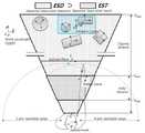
도 1은 자기 시점 부분공간 획득(egocentric subspace acquisition)을 평면화해서 나타낸 도면이고, 도 2는 모든 구성요소들과 좌표계가 있는 자기시점 상호작용 공간의 탑 뷰(top view)이다.Figure 1 is a plan view of an egocentric subspace acquisition, and Figure 2 is a top view of a self-view interaction space with all components and a coordinate system.
도 1 및 도 2를 참조하면, 자기 시점 메타포어(egocentric metaphor)에서 부분 공간 획득을 이용하기 위해서, 본 발명은 사전에 외부요인들을 디자인해야 한다. 왜냐하면 그것은 멀리 떨어진 지역, 사용자 및 입력 장치에 대한 명확한 상호작용 공간들의 고려를 위해서 요구된다. 실제 공간 상에서 가상의 관심 물체(object of interest (OoIs))들이 등록된 증강 공간은 세계 좌표 시스템(world coordinate system)을 가진다. 이 공간의 모든 물체는 세계 좌표와 결합되어 있으나 또한 자신의 변환과 함께 지역의 좌표계를 가진다. 카메라가 달린 HWD(head-worn display, 이하 HWD 라 한다)를 쓰고 있는 사용자는 이 공간에서 개별적인 물체이다. 본 발명은 원근 투영 가상 카메라의 원점으로 사용자의 좌표 시스템을 설정한다. 그러므로 그것은 모든 추적 가능한 물체들의 상대적인 변환으로 계산된다. 이러한 맥락으로, 카메라의 뷰잉 절두체(viewing frustum)에 기반한 큰 체적은 이상적인 자기시점(egocentric) 상호작용 공간들로 정의된다.Referring to Figures 1 and 2, in order to utilize subspace acquisition in an egocentric metaphor, the present invention must design external factors in advance. Because it is required for consideration of clear interaction spaces for remote areas, users and input devices. The augmented space in which virtual object of interest (OoIs) are registered in real space has a world coordinate system. All objects in this space are combined with world coordinates, but also have local coordinate systems with their transformations. A user wearing a head-worn display (HWD) with a camera is a separate object in this space. The present invention sets the user's coordinate system as the origin of the perspective projection virtual camera. Therefore, it is calculated as the relative transformation of all traceable objects. In this context, large volumes based on the viewing frustum of a camera are defined as ideal egocentric interaction spaces.
자기시점(egocentric) 상호작용 공간들은 도 2에 도시한 바와 같이 주된(primary) 상호작용 기준들에 의존하는 두 부분으로 분리된다. 탐지 범위 내의 자기시점 공간(Egocentric Space within Detection(ESD), 이하 ESD라 한다)은 사용자의 관측시야(field of view(fov), 이하 fov라 한다)에 의해 필터된 더 큰 절두체(frustum)이다. 멀리 떨어져 있는 모든 현실 및 가상의 물체들은 여기에 상주하고 사용자 좌표와 관련 있는 그것의 변환을 가진다. 선택된 부분 공간의 변환도 이 공간에서 생성된다. 절두체(frustum)의 크기는 가상 카메라의 클리핑 디스턴스(clipping distance)에 의해 결정된다. 사실은 이것은 사용가능한 트래커(tracker) 및 목표 증강 공간을 위한 그것의 성능과 단단하게 연결되어있다. IsoScale 평면은, 자신만의 기하학적 변환을 가지며 사용하는 디스플레이 스크린의 픽셀 크기와 폭과 높이가 같은, 모든 간접 제어에서 크기가 조절된 매핑(mapping)을 위하여 유용하다. 본 발명은 다음의 두 가지 조건들로부터 IsoScale 평면의 변환을 얻을 수 있다. 첫 번째 IsoScale 평면의 위치는 ESD의 센터라인 상이다. 두 번째 IsoScale 평면의 z 거리는 ESD의 클리핑(clipping) 평면에 비례한다.The egocentric interaction spaces are separated into two parts, as shown in FIG. 2, which depend on the primary interaction criteria. (ESD) within a detection range is a larger frustum filtered by the user's field of view (fov) (hereinafter referred to as fov). All real and imaginary objects that are far apart reside here and have its transformation related to user coordinates. Transformation of the selected subspace is also created in this space. The size of the frustum is determined by the clipping distance of the virtual camera. In fact, it is tightly coupled with its performance for available tracker and target intensification space. IsoScale planes have their own geometric transformations and are useful for mapped scaling on all indirect controls with the same width and height as the pixel size of the display screen you are using. The present invention can obtain the transformation of the IsoScale plane from the following two conditions. The position of the first IsoScale plane is on the center line of the ESD. The z-distance of the second IsoScale plane is proportional to the clipping plane of the ESD.
반면에, 터치 범위 내의 자기시점(egocentric) 공간(Egocentric Space within Touch(EST), 이하 EST라 한다)은 실시간 3차원 핀치-팁(pinch-tip) 탐지에 의한 프리핸드 포인터들을 위하여 뷰잉 절두체보다 작다. EST의 크기는 모터 공간과 ESD 사이에 겹쳐진 공간에 맞먹는다. 그러므로 이것은 양 손들을 사용하는 사용자의 동작을 위하여 3차원 지역에서 도달 가능하고 볼 수 있다.


부분 공간은 인접한 관심 물체(object of interest)들(OoIs)의 상황 정보 및 그것의 환경들을 포함하는 기하학적 변환을 이용하여 3차원 물체로 새롭게 생성된다.The subspace is newly created as a three-dimensional object using geometric transformations that include the context information of the adjacent object of interest (OoIs) and its environments.
본 발명을 통해 풀고자 하는 문제는 기존의 단일 객체 선택이나 레퍼런싱(referencing)을 돕기 위한 여러 볼륨 선택(volumetric selection)과 달리, 정교하게 원거리의 관심 삼차원 영역을 얻기 위한 자기시점 선택(egocentric selection)을 제시하는 것이다.The problem to be solved by the present invention is that, unlike the volumetric selection for helping existing single object selection or referencing, it is difficult to precisely select egocentric selection for obtaining a distant three- ).
단안 비디오 투과(monocular video see-through) HWD를 사용하는 환경에 집중하므로 부분 공간 선택은 하나의 시각 절두체(view frustum) 내에서 이루어진다. 이 절두체(view frustum)를 상호작용 대상에 따라 두 자기시점 공간(egocentric space)으로 구분하면 다음과 같다. 먼저 ESD는 검출과 추적 기술(detection and tracking)이 동작하는 시각 절두체 내 큰 절두체로 손에 닿지 않는 거리의 실제와 가상의 객체들이 주로 상주하는 공간이다. 그러므로 객체들을 포함하는 선택된 부분 공간은 ESD에 존재한다. 반면, EST는 운동 공간(motor space)과 ESD의 교집합으로 이루어지는 작은 절두체(smaller frustum)이다. EST는 부분 공간(subspace) 선택을 위해 양손에 의한 삼차원 손 입력(3D hand input)이 동작하는 공간이다.Monocular video see-through Focusing on the environment using HWD, subspace selection occurs within a single view frustum. This view frustum is divided into two self-view spaces according to interaction objects. First, ESD is a large frustum in the visual frustrum where detection and tracking operates. It is a space in which real and virtual objects that do not reach the hand mainly reside. Therefore, the selected subspace containing objects exists in the ESD. On the other hand, EST is a smaller frustum consisting of intersection of motor space and ESD. The EST is a space in which 3D hand input by both hands is operated for subspace selection.
본 발명은 ESD 내 관심 객체들과 그 주변 영역을 포함하는 임의의 크기와 형태를 갖는 부분 공간(subspace)을 새롭게 정의한다. 부분 공간(subspace)은 다음의 고려사항들을 만족하는 직육면체(cuboid)로 정한다.The present invention newly defines a subspace having an arbitrary size and shape including objects of interest in the ESD and surrounding areas thereof. The subspace is defined as a cuboid that satisfies the following considerations:
1. 적어도 하나 이상의 객체를 포함하는 공간이다. 객체가 영향을 미치지 않는 비어있는 공간은 사용자에 의해 선택되더라도 활용될 가능성이 거의 없기 때문이다.1. A space containing at least one object. This is because an empty space in which an object does not affect is unlikely to be utilized even if it is selected by the user.
2. 전역 좌표 시스템(global coordinate system)을 기준으로 하는 위치(position), 회전(rotation), 스케일(scale) 값을 포함하는 삼차원 기하정보를 반드시 가진다.2. It must have three-dimensional geometry information including position, rotation, and scale values based on the global coordinate system.
3. 정형화된 기하 형태로 표현이 가능해야 한다. 착용형 증강현실 시스템의 관점에서 원거리 삼차원 부분 공간을 기술하고 조작하기 위한 계산 비용(computational cost)을 줄이는 것이 중요하다. 시간과 장소의 구애를 덜 받는 맨손 입력을 이용하는 착용형 컴퓨팅 시스템이니 만큼, 부분 공간 기술에 필요한 데이터와 계산이 적을수록 좋은 시스템 퍼포먼스를 유지할 수 있다. 규칙이 없는 비정형의 기하 부분 공간은 계산 부담(computational load)를 가중시키고 사용자의 조작을 복잡하게 만든다.3. It should be able to be expressed in the form of a regular geometry. It is important to reduce the computational cost of describing and manipulating distant three-dimensional subspaces in terms of a wearable augmented reality system. As a wearable computing system that uses bare-handed inputs that are less subject to time and space constraints, fewer data and calculations required for subspace technology can maintain good system performance. Atypical geomorphic subspace with no rules increases the computational load and complicates the operation of the user.
4. 비균일 스케일(non-uniform scale)의 공간도 커버 할 수 있는 형태이어야 한다. 구체나 큐브와 같은 균일 스케일 형태는 길쭉하거나(longish) 넓고 평평한(wide and flat) 관심 삼차원 영역을 기술하기에 적합하지 않다. 특히, 구체는 사용자가 추가적인 정보 없이 회전을 판단하기가 어렵다.4. It shall be of a type that can cover a space of non-uniform scale. Uniform scale shapes such as spheres and cubes are not suitable for describing long and wide and flat areas of interest. In particular, spheres are difficult for a user to determine rotation without additional information.
위의 고려사항을 토대로, 본 발명은 증강 공간에서의 부분 공간 획득을 EST에서 삼차원 맨손 입력을 이용하여 ESD상의 관심 객체를 포함하는 임의의 원거리 직육면체의 위치, 회전, 스케일을 효과적으로 결정하는 문제로 단순화한다.Based on the above considerations, the present invention simplifies the problem of determining the position, rotation, and scale of arbitrary long rectangular cubes including the object of interest on the ESD using the three-dimensional bare-hand input in the EST, do.
인지(Perception)는 증강 장면(augmented scene) 내 사용자가 원하는 부분 공간에 대응하는 예상 부분 공간(imaginary subspace)을 얻는 단계이다. 이는 사용자의 맨손 상호작용에 의한 부분 공간 구체화를 위해 필수적인 정신적 선택 과정(mental selection process)이다. 먼저 사용자는 사용자의 위치와 증강 객체들의 시각(perspective)을 고려한 fov를 찾는다. 이 때의 시점(viewport)은 추후 공간 단위의 상호작용 의도를 충분히 반영한다. 특히, 공간 상에서의 사용자가 바라보는 fov는 부분 공간 선택시 회전 정보를 시스템에게 제공하는 중요한 단서이다. 사용자가 머무른 fov에서, 관심 영역을 한정 짓기 위한 시각 인지 과정(human visual recognition process)에 의해 예상 공간 그리기(imaginary subspace drawing)를 매우 빠르게 수행한다. 사람의 눈은 시야 내 관심도에 따라 중심시각(central vision)에 의해 집중되는 영역과 중심외시각(peripheral vision)에 의해 집중되지 않는 영역으로 구분된다. 따라서, 중심시각의 자취(trace)에 의한 연속적인 포커스 영역(focused area)은 곧 사용자 시선에서의 관심 영역이라 할 수 있다. 이와 같이 자기시점에서의 인지 단계는 비정형화된 삼차원 관심 부분 영역을 기억하고 타겟팅(targeting)과 개선(refinement) 단계를 통해 자연스럽게 이를 정형화된 영역으로 재현한다.Perception is a step of obtaining an imaginary subspace corresponding to a subspace desired by a user in an augmented scene. This is a mental selection process that is essential for the user to specify the subspace by bare-hand interaction. First, the user searches for fov considering the user's position and the perspective of the augmented objects. The viewport at this time fully reflects the spatial intent of the interaction in the future. In particular, the fov the user sees in space is an important clue to provide the system with rotation information when selecting the subspace. In the fov where the user is staying, imaginary subspace drawing is performed very quickly by a human visual recognition process to define the region of interest. The human eye is divided into a region concentrated by central vision and a region concentrated by peripheral vision according to the degree of interest in sight. Therefore, a continuous focused area due to traces of the central time can be regarded as a region of interest in the user's gaze. As such, the recognition step at the self-viewpoint memorizes the atypical three-dimensional interest area and reproduces it as a regular area naturally through targeting and refinement steps.
도 3은 본 발명의 일실시예에 의한 증강 공간 내 부분 공간 획득 시스템의 구성을 나타낸 도면이다.3 is a diagram illustrating a configuration of a partial space acquisition system in an augmented space according to an embodiment of the present invention.
도 3을 참조하면, 본 발명의 일실시예에 의한 증강 공간 내 부분 공간 획득 시스템은 깊이 영상 획득 장치(300), 디스플레이 장치(310), 타겟팅부(320) 및 개선부(330)을 포함한다.3, a partial space acquisition system in an augmented space according to an embodiment of the present invention includes a depth
깊이 영상 획득 장치(300)는 마이크로소프트(Microsoft)사에서 출시된 키넥트가 사용될 수 있으나 이에 한정되는 것은 아니고, 깊이 정보를 제공할 수 있는 장치라면 모두 사용 가능하다.The depth
깊이 영상 획득 장치(300)는 RGB Color 카메라, 3D Depth 센서, 4개의 마이크로폰 어레이 및 센서를 상하로 움직일 수 있는 틸트 모터를 주요하게 포함하여 구성된다. 따라서 깊이 영상 획득 장치(300)는 상기 3D Depth 센서로부터 3D 이미지를 획득하는 것이 가능하다.The depth
디스플레이 장치(310)는 단안 비디오 투과(monocular video see-through) HWD 일 수 있으나 이에 한정되는 것은 아니고 상기 깊이 영상 획득 장치(300)로부터 획득된 3D 이미지를 디스플레이 가능한 것이면 모두 가능하다.The
타겟팅부(320)는 디스플레이 장치에서 표시되는 3D 이미지에서 사용자의 동작에 의한 이벤트가 발생되면, 상기 사용자의 동작에 대응하는 제1 입체형상의 제1 부분 공간을 획득한다.The targeting
개선부(330)는 상기 타겟팅부가 획득한 제1 부분 공간의 범위 내에서 사용자의 제스쳐에 따라 위치와 스케일이 조절되는 제2 입체형상의 제2 부분 공간을 획득한다.The
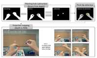
도 4는 3D 핀치-팁(pinch-tip) 입력을 구현하는 방법을 나타낸 도면이다.4 is a diagram illustrating a method for implementing a 3D pinch-tip input.
본 발명은 직접 도달하기 어려운 증강 공간 내 부분 공간을 원거리에서 선택하기 위한 실시간 맨손 입력을 직접 구현하였다. HWD(Head worn display)에 부착된 RGBD 카메라에 의해 추가 장치의 도움 없이 EST(Egocentric Space within Touch)에서 3D 핀치 위치와 동작을 인식한다.The present invention directly implements a real-time bare-hand input for selecting a partial space in an augmented space which is difficult to reach directly from a long distance. It recognizes 3D pinch position and motion in EST (Egocentric Space Within Touch) without the aid of additional device by RGBD camera attached to HWD (Head worn display).
윌슨(Wilson)과 하(Ha)의 방식으로부터 빠르고 강건한 착용형 AR 환경에서의 삼차원 핀치 입력 도구로의 영감을 얻었다. 복잡한 손 특징 검출이나 학습 알고리즘과 달리, 윌슨은 고정된 RGB 입력에서의 차영상(image subtraction)을 통해 간단하고 강건한 핀칭 홀 검출 방법을 제안하였다. 또한, 하는 1인칭 시점(egocentric metaphor)에서 HWD에 부착된 RGB-D 카메라로부터 검출된 팜의 좌표를 통합한 착용형 AR 좌표 시스템을 제안하였다.From Wilson and Ha's method, I was inspired by a three-dimensional pinch input tool in a fast and robust wearable AR environment. Unlike complex hand feature detection and learning algorithms, Wilson proposed a simple and robust pinhole detection method with image subtraction at fixed RGB input. We also proposed a wearable AR coordinate system that integrated the coordinates of the palm detected from the RGB-D camera attached to the HWD at the first-person (egocentric) metaphor.
본 발명은 HWD에 부착된 깊이 센서(깊이 영상 획득 장치)로부터 핀치 홀에 의한 핀치 팁 위치를 보다 빠르게 검출하고 이를 HWD를 기준으로 하는 삼차원 좌표 시스템에 결합하였다.The present invention detects the position of a pinch tip by a pinch hole from a depth sensor attached to the HWD more quickly and combines it with a three-dimensional coordinate system based on HWD.
도 4는 양손 구분이 가능한 positional 3DoF 핀치팁 입력의 구현 결과이다. 1인칭 시점 환경에서 운동학적으로 팔이 화면 가장자리(boundary)와 만나는 조건과 홀 중심으로부터의 픽셀 두께 검사를 통해 일반적인 상황에서 양손을 빠르고 강건하게 구별하도록 구현하였다.Figure 4 shows the result of implementing a positional 3DoF pinch tip input with two-hand separation. In the first person view environment, we implemented the system to discriminate both hands quickly and robustly in the normal situation through the condition that the arm meets the screen boundary and the pixel thickness from the hole center.
검출된 3D 위치는 EST 내 가상 손 메타포로 사용이 가능하다. 하지만 본 발명에서는 2차원 RGB화면에 매핑되어 타겟팅부(320)에서 2D 커서로 활용하고 개선부(330)에서 cuboid의 깊이 조절을 위한 1D 컨트롤러로 분리하여 활용한다. 핀치 입력 도구의 상태는 유휴(idle), 핀칭(pinch), 그리고 해제(release)로 구분되며 선택(selection trigger)은 하이젠버그 효과(Heisenberg effect)를 줄이기 위한 선택하기 위해 해재(release to select) 방식을 적용하였다.The detected 3D position can be used as a virtual hand metaphor in the EST. However, in the present invention, the
도 4를 참조하면, (1) HWD에 부착된 깊이 영상으로부터 얻은 이진 이미지와 구멍을 채운 이미지를 얻고, (2) 이 두 이미지 간의 차영상으로부터 핀치 홀에 해당하는 영상을 획득한다.Referring to FIG. 4, (1) a binary image obtained from the depth image attached to the HWD and an image filled with holes are obtained, and (2) an image corresponding to a pinch hole is obtained from the difference image between the two images.
(3) 타원 피팅에 의한 중심점 계산 및 손 구별 조건을 통해 해당 핀치의 손을 구별한다. 이를 자세히 살펴보면, (a)1인칭 시점에 정상적으로 손이 들어온다는 가정하에 검출 타원의 중심점으로부터 x축(수평 방향)으로 두께 검사(픽셀개수를 비교)를 수행한다(예를 들면, 왼쪽이 두꺼울 경우 왼 손). (b)1차검사 시 왼쪽 또는 오른쪽의 바운더리와 만날 시에는 해당 손의 이미지 바운더리 접촉 검사 추가 수행한다.(3) The pinch hand is distinguished through the calculation of the center point by elliptic fitting and the hand discrimination condition. (A) Thickness inspection (comparison of the number of pixels) is performed on the x-axis (horizontal direction) from the center point of the detection ellipse on the assumption that the hand normally comes in at the first person's time (for example, Left hand). (b) In case of encountering the boundary on the left or right side during the first inspection, the image boundary touch test of the hand is performed.
(4) 손 구별 후 convex점들 중 가장 먼 거리의 핀치 팁을 선택한다.(4) Select the pinch tip that is the farthest from the convex points.
(5) 사전에 주어진 캘리브레이션에 따라 2D 포인트를 RGB 영상의3D (2D 위치+깊이)로 프로젝션한다.(5) Project the 2D point to 3D (2D position + depth) of the RGB image according to the calibration given in advance.
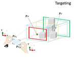
도 5는 타겟팅부의 내부 구성을 나타낸 도면이고, 도 6은 타겟팅부의 동작을 평면화해서 나타낸 도면이다.FIG. 5 is a diagram showing the internal configuration of the targeting unit, and FIG. 6 is a diagram showing the operation of the targeting unit in a plan view.
타겟팅부(320)는 fov에 등장하는 객체들의 공간 맥락(spatial context)을 고려하여 예상 부분 공간(imaginary subspace)을 포함하는 최대 스케일의 초기 부분 공간을 구하는 부분이다.The targeting
사용자에 의해 그려지는 2D 관심 영역(Region of Interest(RoI),이하 RoI라 한다)를 지나는 터널 내 객체 충돌 정보를 활용하여 초기 부분 공간에 해당하는 큰 직육면체를 얻는다. 이렇게 얻어낸 공간은 반드시 예상 부분 공간을 포함한다.A large rectangular parallelepiped corresponding to the initial partial space is obtained by using the object collision information in the tunnel passing through the 2D region of interest (RoI, hereinafter referred to as RoI) drawn by the user. The space thus obtained necessarily contains the expected subspace.
도 5 및 도 6을 참조하면, 타겟팅부(320)는 이벤트 감지부(321), 투영부(322), 터널 캐스팅 수행부(323) 및 제1변환부(324)를 포함한다.Referring to FIGS. 5 and 6, the targeting
이벤트 감지부(321)는 상기 3D 이미지에서 사용자의 동작을 이벤트 발생으로 결정한다.The
즉, 이벤트 감지부(321)는 상기 3D 이미지에서 사용자의 양손 핀치팁 포인터에 의한 핀치/릴리즈(pinch and release) 이벤트 동작을 사용자의 동작에 의한 이벤트 발생으로 결정한다.That is, the
구체적으로 이벤트 감지부(321)는 사용자의 양손 핀치팁 포인터에 의한 핀치/릴리즈(pinch and release) 동작을 이용하여 HWD 화면 상에 관심 삼차원 영역이 포함되는 RoI 프레임을 그린다. 이 때의 프레임 크기는 이후 설명될 사용자의 눈으로부터 생성되는 터널의 너비와 높이를 결정하는 핵심 정보이다.Specifically, the
투영부(322)는 상기 이벤트 감지부(321)에서 결정된 사용자의 동작으로 형성된 2D 프레임을 3D공간으로 투영(projection)하여 터널을 형성한다.The
즉, 투영부(322)는 상기 3D 이미지에서 사용자의 양손 핀치팁 포인터에 의한 핀치/릴리즈(pinch and release) 동작으로 형성된 2D 프레임을 3D 공간으로 투영하여 터널을 형성한다. That is, the
구체적으로, 투영부(322)는 상기 이벤트 감지부(321)에서 관심 삼차원 영역이 포함되어 그려진 RoI 프레임을 터널로 확장하기 위해 먼저 화면에 그려진 2D 프레임을 3D 공간으로 프로젝션(projection)한다. 이는 HWD의 픽셀 해상도(pixel resolution)와 같은 스케일(isomorphic scale)을 가지는 동일 스케일 평면(IsoScale plane)을 이용하여 해결한다. 이 때의 동일 스케일 평면은 z 값을 제외하고, 카메라 좌표계의 원점과 동일한 이동(translation)과 회전(rotation)을 가지는 삼차원 상의 이차원 평면이다. 동일 스케일 평면의 z값은 카메라 절두체를 구성하는 가까운(near) 또는 먼 평면(far plane)과의 비례식을 이용하여 쉽게 계산할 수 있다. 이처럼 동일 스케일 평면은 스크린 좌표를 사용하는 여러 가림 선택(occlusion selection)에 효과적으로 활용 가능하다. 이렇게 RoI를 지나는 터널에서의 유효 영역은 이후 설명될 양방향 터널 캐스팅(Two-way tunnel-casting)을 통해 결정한다.Specifically, the projecting
터널 캐스팅 수행부(323)는 상기 투영부(322)에 의해 형성된 터널에 광선 그룹을 투사하여 포워드 캐스팅(forward casting) 및 백워드 캐스팅을 수행한다.The tunnel
즉, 터널 캐스팅 수행부(323)는 사용자의 눈으로부터 투사된 광선 그룹이 상기 터널에 존재하는 증강 객체들과 최초로 충돌하는 눈으로부터 가장 가까운 최초 충돌 지점을 찾는 포워드 캐스팅 및 상기 포워드 캐스팅과 동일한 광선 그룹을 반대 방향으로부터 투사하여 상기 터널에 존재하는 증강 객체들과 최초로 충돌하는 눈으로부터 가장 먼 최초 충돌 지점을 찾는 백워드 캐스팅을 수행한다.In other words, the
구체적으로, 터널 캐스팅 수행부(323)의 양방향 터널 캐스팅은 시각 절두체의 끝까지 뻗어나가는 터널에서 객체들이 존재하는 유효 영역만을 한정하는 자동 선별 방법이다. 기본적으로 부분 공간은 객체들을 중심으로 이루어지므로, 전체 터널에서 맨 앞과 맨 뒤 빈(void) 영역을 제외한다. 본 발명에서는 이를 포함 절두체(inclusive frustum)라고 부른다. 양방향 터널 캐스팅에서는 터널 캐스팅을 수행하는 광선 그룹(set of rays)과 충돌하는 증강 객체들의 맥락을 충분히 활용한다. 먼저, 눈으로부터 가장 가까운, 최초 충돌지점을 찾는 포워드 캐스팅(forward casting)을 수행한다. 이 때, 최단거리 충돌점을 포함하는 터널과 평행한 슬라이스 평면을 포함 절두체의 가까운 평면(near-plane)(제1평면)으로 정한다. 포함 절두체의 먼 평면(far-plane)을 정하기 위해서는 백워드 캐스팅을 수행한다. 이는 눈에서 가장 먼 충돌점을 찾기 위한 과정으로, 포워드 캐스팅과 동일한 광선 그룹을 반대 방향에서 발사하여 최초 충돌지점을 찾는다. 이렇게 얻은 충돌지점을 포함하는 터널과 평행한 슬라이스 평면은 포함 절두체의 먼 평면(far-plane)(제2평면)으로 정한다. 터널 내 슬라이스 된 제1 및 제2평면으로 포함 절두체의 크기가 결정된다.Specifically, the bidirectional tunnel casting of the
제1변환부(324)는 터널 캐스팅 수행부에서 수행하여 획득된 절두체(frustum)를 변환하여 제1 입체형상의 제1 부분 공간을 획득한다.The
즉, 제1변환부(324)는 상기 터널 캐스팅 수행부(323)에서 설명한 바와 같이 상기 눈으로부터 가장 가까운 최초 충돌 지점을 포함하는 상기 터널과 평행 슬라이스 평면인 제1평면과 상기 눈으로부터 가장 먼 최초 충돌 지점을 포함하는 상기 터널과 평행 슬라이스 평면인 제2평면으로 구성되는 절두체(frustum)의 중간을 기준으로 미리 정해진 부분 공간의 정의에 맞게 동일한 위치, 회전 및 부피를 가지는 제 1입체형상으로 변환하여 제1 부분 공간을 획득한다.That is, as described in the tunnel casting
제1변환부(324)에서 변환한 제1 입체형상은 직육면체인 것이 적합하나 입체형상의 모양이 이에 한정되는 것은 아니다.The first three-dimensional shape converted by the first converting
도 7은 개선부의 내부 구성을 나타낸 도면이고, 도 8은 개선부의 동작을 평면화해서 나타낸 도면이다.Fig. 7 is a diagram showing the internal configuration of the improvement section, and Fig. 8 is a diagram showing the operation of the improvement section in a plan view.
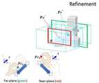
개선부(330)는 유사한 핀치 인터랙션을 통해 초기 부분 공간 범위 내에서 위치와 스케일을 조절하여 최종 부분 공간인 제2 입체형상의 제2 부분 공간을 결정한다. 상기 타겟팅부(320)에서 앞과 뒤 쪽의 빈 공간이 제외되었지만, 여전히 자기시점에서 가림이나 깊이 인지 등에 의해 원치 않는 객체들이 포함되는 경우가 있기 때문이다. 따라서 사용자 슬라이싱에 의하여 앞과 뒤쪽에 포함된 불필요한 공간을 다시 제거한다. 사용자는 포함 절두체의 가까운 그리고 먼 평면의 위치를 직접 변경하여 원하는 부분 공간에 근접한 결과를 얻을 수 있다.The
도 7 및 도 8을 참조하면, 개선부(330)는 조절부(331), 탑뷰 제공부(332) 및 제2변환부(333)을 포함한다.Referring to FIGS. 7 and 8, the
조절부(331)는 상기 타겟팅부(320)가 획득한 제1 부분 공간의 범위 내에서 사용자의 양손 핀치 제스쳐를 통해 새로운 부분 공간을 형성한다.The adjusting
즉, 조절부(331)는 상기 타겟팅부(320)가 획득한 제1 부분 공간의 범위 내에서 사용자의 양손 핀치 제스쳐에 따른 상대 스케일 매핑(relative scale mapping)을 통해 직접 변경하여 새로운 부분 공간을 형성한다.That is, the
구체적으로 조절부(331)는 포함 절두체의 두 평면은 양 손 핀치 제스쳐에 따른 상대 스케일 매핑(relative scale mapping)을 통해 수행한다. 이는 정해진 운동 공간에서 가변 깊이를 가지는 포함 절두체를 효과적으로 슬라이스하기 위함이다. 따라서 타겟팅부(320)에서 포함 절두체의 물리적인 거리가 결정될 때, 핀치 입력의 깊이 측정 허용 범위에 맞게 스캐일 매핑 비(scale mapping ratio)가 조금씩 변할 수 있다. 이는 아주 세밀한 깊이 조절에는 적합하지 않지만, 빈번한 클러칭(clutching)을 없이 처음과 끝을 탐색하기에 효과적이다. 본 발명은 주사용(dominant)과 아닌(nondominant) 손을 각각 가까운 그리고 먼 평면에 각각 대응한다. 각 손에 대응된 면의 이동은 포함 절두체를 내에서 독립적으로 동작하며 먼 평면은 가까운 평면을 넘어가지 못하도록 설계한다. 해당 면의 이동이 이루어질 때마다, 새로운 직육면체 변환이 수행된 결과가 사용자에게 제공된다.Specifically, the
탑뷰 제공부(332)는 상기 타겟팅부(320)가 획득한 제1 부분 공간의 탑뷰를 제공하여 사용자의 양손 핀치 제스쳐를 통해 상기 조절부(331)가 부분공간을 형성하는 것을 돕는다.The top
즉, 탑뷰 제공부(332)는 상기 타겟팅부(320)가 획득한 제1 부분 공간의 스케일을 고려한 직교 투영(orthogonal projection)에 의한 탑뷰를 제공하여 사용자의 양손 핀치 제스쳐를 통해 상기 조절부(331)가 부분공간을 형성하는 것을 돕는다.That is, the top
구체적으로, 탑뷰 제공부(332)는 사용자의 깊이 조절을 돕기 위해 가상 카메라인 즉시적인 맵(instant map)을 추가로 제공한다. 초기 부분 공간에의 고정된 회전이 사용자의 이동에 따른 뷰포트 전환에도 깊이 조절을 가능하게 하지만, 매번 가림을 피하고 깊이를 확인하는 작업은 매우 불편하다. 이를 해결하기 위해 즉시적인 맵은 게임이나 네비게이션과 같이 사용자가 자기시점에서 볼 수 없는 관심 영역의 탑 뷰를 제공해준다. 구글글래스 디스플레이와 유사한 우측상단에 포함 절두체의 위치에서 그 스케일을 고려한 직교 투영(orthogonal projection)에 의한 가상 탑뷰 카메라를 제공한다. 따라서 사용자는 보다 쉽고 빠르게 양 면의 깊이 이동과 그에 따른 부분 공간 변환 결과를 눈으로 확인할 수 있다.Specifically, the
제2변환부(333)는 상기 조절부(331)에 의해 새롭게 형성된 부분공간을 변환하여 제2 입체형상의 제2 부분 공간을 획득한다.The second converting
제2변환부(333)는 상기 조절부에 의해 새롭게 형성된 부분공간을 미리 정해진 부분 공간의 정의에 맞게 동일한 위치, 회전 및 부피를 가지는 제2 입체형상으로 변환하여 제2 부분 공간을 획득한다.The
제2변환부(333)에서 변환한 제2 입체형상은 직육면체인 것이 적합하나 입체형상의 모양이 이에 한정되는 것은 아니다.The second solid shape converted by the
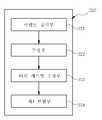
도 9는 본 발명의 일 실시예에 의한 증강 공간 내 부분 공간 획득 방법을 나타낸 흐름도이다.9 is a flowchart illustrating a method of acquiring a partial space in an enhanced space according to an embodiment of the present invention.
도 9를 참조하면, 이벤트 감지부(321)가 3D 이미지에서 사용자의 동작을 이벤트 발생으로 결정한다(S900). 즉, 상기 이벤트 감지부(321)는 상기 3D 이미지에서 사용자의 양손 핀치팁 포인터에 의한 핀치/릴리즈(pinch and release) 이벤트 동작을 사용자의 동작에 의한 이벤트 발생으로 결정한다.Referring to FIG. 9, the
투영부(322)가 상기 결정된 사용자의 동작으로 형성된 2D 프레임을 3D공간으로 투영하여 터널을 형성한다(S910). 즉, 상기 투영부(322)는 상기 3D 이미지에서 사용자의 양손 핀치팁 포인터에 의한 핀치/릴리즈(pinch and release) 동작으로 형성된 2D 프레임을 3D 공간으로 투영하여 터널을 형성한다.The
터널 캐스팅 수행부(323)가 상기 형성된 터널에 광선 그룹을 투사하여 포워드 캐스팅 및 백워드 캐스팅을 수행한다(S920). 즉, 상기 터널 캐스팅 수행부(323)는 사용자의 눈으로부터 투사된 광선 그룹이 상기 터널에 존재하는 증강 객체들과 최초로 충돌하는 눈으로부터 가장 가까운 최초 충돌 지점을 찾는 포워드 캐스팅 및 상기 포워드 캐스팅과 동일한 광선 그룹을 반대 방향으로부터 투사하여 상기 터널에 존재하는 증강 객체들과 최초로 충돌하는 눈으로부터 가장 먼 최초 충돌 지점을 찾는 백워드 캐스팅을 수행한다.The tunnel
제1변환부(324)가 상기 포워드 캐스팅 및 백워드 캐스팅을 수행하여 획득된 절두체(frustum)를 변환하여 제1 입체형상의 제1 부분 공간을 획득한다(S930). 즉, 상기 제1변환부(324)는 상기 눈으로부터 가장 가까운 최초 충돌 지점을 포함하는 상기 터널과 평행 슬라이스 평면인 제1평면과 상기 눈으로부터 가장 먼 최초 충돌 지점을 포함하는 상기 터널과 평행 슬라이스 평면인 제2평면으로 구성되는 절두체(frustum)의 중간을 기준으로 미리 정해진 부분 공간의 정의에 맞게 동일한 위치, 회전 및 부피를 가지는 제 1입체형상으로 변환하여 제1 부분 공간을 획득한다.The first transforming
조절부(331)가 상기 획득한 제1 부분 공간의 범위 내에서 사용자의 양손 핀치 제스쳐를 통해 새로운 부분 공간을 형성한다(S940). 즉, 상기 조절부(331)는 상기 타겟팅부가 획득한 제1 부분 공간의 범위 내에서 사용자의 양손 핀치 제스쳐에 따른 상대 스케일 매핑(relative scale mapping)을 통해 직접 변경하여 새로운 부분 공간을 형성한다.The
제2변환부(333)가 상기 새롭게 형성된 부분공간을 변환하여 제2 입체형상의 제2 부분 공간을 획득한다(S950). 즉, 상기 제2변환부(333)는 상기 조절부에 의해 새롭게 형성된 부분공간을 미리 정해진 부분 공간의 정의에 맞게 동일한 위치, 회전 및 부피를 가지는 제2 입체형상으로 변환하여 제2 부분 공간을 획득한다.The second transforming
도 6은 타겟팅부의 동작을 평면화해서 나타낸 도면이고, 도 8은 개선부의 동작을 평면화해서 나타낸 도면이다.Fig. 6 is a plan view of the operation of the targeting unit, and Fig. 8 is a plan view of the operation of the improvement unit.
도 6 및 도 8을 참조하면, 본 발명의 타겟팅부(320) 및 개선부(330)에 의하여 획득된 제2 입체형상의 제2 부분 공간의 중심을
회전(

위치(
[수학식 1][Equation 1]

여기에서, 새로운 평면의 중심 위치

또한,


스케일(
[수학식 2]&Quot; (2) "

여기에서,


본 발명은 교육, 비즈니스, 원격진료 및 다자간 학습 등에 이용 가능하고, 부분 공간을 획득하여 부분 공간 안에 존재하는 객체들과의 상호작용이 필요한 분야라면 어떤 분야에도 적용 가능하다.The present invention can be applied to education, business, telemedicine, and multi-party learning, and can be applied to any field where a partial space is acquired and interaction with objects existing in a subspace is required.
이상에서 본 발명에 의한 바람직한 실시예를 참조하여 설명하였지만, 해당 기술 분야의 숙련된 당업자는 하기의 청구의 범위에 기재된 본 발명의 사상 및 영역의 범위 내에서 본 발명을 다양하게 수정 및 변경시킬 수 있음을 이해할 수 있을 것이다.It will be apparent to those skilled in the art that various modifications and variations can be made in the present invention without departing from the spirit or scope of the invention as defined in the following claims. It can be understood that.
300.....깊이 영상 획득 장치 310.....디스플레이 장치
320.....타겟팅부 330.....개선부300 ..... depth
320 ..... targeting
Claims (13)
Translated fromKorean상기 타겟팅부가 획득한 제1 부분 공간의 범위 내에서 사용자의 제스쳐에 따라 위치와 스케일이 조절되는 제2 입체형상의 제2 부분 공간을 획득하는 개선부(Refinement)를 포함하며,
상기 타겟팅부는
상기 3D 이미지에서 사용자의 동작을 이벤트 발생으로 결정하는 이벤트 감지부;
상기 이벤트 감지부에서 결정된 사용자의 동작으로 형성된 2D 프레임을 3D공간으로 투영(projection)하여 터널을 형성하는 투영부;
상기 투영부에 의해 형성된 터널에 광선 그룹을 투사하여 포워드 캐스팅(forward casting) 및 백워드 캐스팅을 수행하는 터널 캐스팅 수행부; 및
상기 터널 캐스팅 수행부에서 수행하여 획득된 절두체(frustum)를 변환하여 제1 입체형상의 제1 부분 공간을 획득하는 제1변환부
를 포함하는 증강 공간 내 부분 공간 획득 시스템.A targeting unit for acquiring a first subspace of a first stereoscopic image corresponding to an operation of the user when an event by a user's operation is generated in a 3D image displayed on a display device; And
And a refinement that obtains a second subspace of a second stereoscopic shape in which position and scale are adjusted according to a user's gesture within a range of the first subspace acquired by the targeting unit,
The targeting unit
An event detection unit for determining an operation of a user as an event occurrence in the 3D image;
A projection unit for projecting a 2D frame formed by a user's operation determined by the event sensing unit into a 3D space to form a tunnel;
A tunnel casting unit performing a forward casting and a backward casting by projecting a light beam group to a tunnel formed by the projection unit; And
A first transform unit for transforming a frustum obtained by performing the tunnel casting unit to obtain a first subspace of a first stereoscopic shape,
And a second space in the reinforcement space.
상기 타겟팅부가 획득한 제1 부분 공간의 범위 내에서 사용자의 제스쳐에 따라 위치와 스케일이 조절되는 제2 입체형상의 제2 부분 공간을 획득하는 개선부(Refinement)를 포함하는
상기 개선부는
상기 타겟팅부가 획득한 제1 부분 공간의 범위 내에서 사용자의 양손 핀치 제스쳐를 통해 새로운 부분 공간을 형성하는 조절부;
상기 타겟팅부가 획득한 제1 부분 공간의 탑뷰를 제공하여 사용자의 양손 핀치 제스쳐를 통해 상기 조절부가 부분공간을 형성하는 것을 돕는 탑뷰제공부; 및
상기 조절부에 의해 새롭게 형성된 부분공간을 변환하여 제2 입체형상의 제2 부분 공간을 획득하는 제2변환부
를 포함하는 증강 공간 내 부분 공간 획득 시스템.A targeting unit for acquiring a first subspace of a first stereoscopic image corresponding to an operation of the user when an event by a user's operation is generated in a 3D image displayed on a display device; And
And a refinement for acquiring a second subspace on a second stereoscopic shape in which position and scale are adjusted according to a user's gesture within a range of the first subspace acquired by the targeting unit
The improvement unit
An adjusting unit for forming a new subspace through the user's two-handed pinch gesture within a range of the first subspace acquired by the targeting unit;
A top view agent that provides a top view of the first subspace acquired by the targeting unit to help the control unit form the subspace through the user's two-handed pinch gesture; And
A second conversion unit for converting a newly formed subspace by the adjustment unit to obtain a second subspace of a second stereoscopic shape,
And a second space in the reinforcement space.
상기 이벤트 감지부는
상기 3D 이미지에서 사용자의 양손 핀치팁 포인터에 의한 핀치/릴리즈(pinch and release) 이벤트 동작을 사용자의 동작에 의한 이벤트 발생으로 결정하는 증강 공간 내 부분 공간 획득 시스템.3. The method of claim 2,
The event detection unit
A pinch and release event operation by the user's two-handed pinch tip pointer in the 3D image is determined as an occurrence of an event by a user's operation.
상기 투영부는
상기 3D 이미지에서 사용자의 양손 핀치팁 포인터에 의한 핀치/릴리즈(pinch and release) 동작으로 형성된 2D 프레임을 3D 공간으로 투영하여 터널을 형성하는 증강 공간 내 부분 공간 획득 시스템.3. The method of claim 2,
The projection unit
And a 2D frame formed by a pinch and release operation by the two-handed pinch tip pointer of the user in the 3D image is projected into a 3D space to form a tunnel.
상기 터널 캐스팅 수행부는
사용자의 눈으로부터 투사된 광선 그룹이 상기 터널에 존재하는 증강 객체들과 최초로 충돌하는 눈으로부터 가장 가까운 최초 충돌 지점을 찾는 포워드 캐스팅 및 상기 포워드 캐스팅과 동일한 광선 그룹을 반대 방향으로부터 투사하여 상기 터널에 존재하는 증강 객체들과 최초로 충돌하는 눈으로부터 가장 먼 최초 충돌 지점을 찾는 백워드 캐스팅을 수행하는 증강 공간 내 부분 공간 획득 시스템.3. The method of claim 2,
The tunnel casting unit
Forward casting for finding the nearest initial collision point from the eye in which the light beam group projected from the user's eye first collides with the augmenting objects present in the tunnel, and projecting the same light beam group as the forward cast from the opposite direction, A partial space acquisition system in an augmented space for performing backward casting to find the first collision point farthest from the first colliding eye.
상기 제1변환부는
눈으로부터 가장 가까운 최초 충돌 지점을 포함하는 상기 터널과 평행 슬라이스 평면인 제1평면과 상기 눈으로부터 가장 먼 최초 충돌 지점을 포함하는 상기 터널과 평행 슬라이스 평면인 제2평면으로 구성되는 절두체(frustum)의 중간을 기준으로 미리 정해진 부분 공간의 정의에 맞게 동일한 위치, 회전 및 부피를 가지는 제 1입체형상으로 변환하여 제1 부분 공간을 획득하는 증강 공간 내 부분 공간 획득 시스템.3. The method of claim 2,
The first conversion unit
The tunnel comprising the first collision point closest to the eye and the second plane being the parallel slice plane including the tunnel comprising the first collision plane in parallel with the first collision plane and the first collision point farthest from the eye, And acquiring a first subspace by transforming the first subspace having the same position, rotation, and volume to the definition of the predetermined subspace based on the intermediate.
상기 조절부는
상기 타겟팅부가 획득한 제1 부분 공간의 범위 내에서 사용자의 양손 핀치 제스쳐에 따른 상대 스케일 매핑(relative scale mapping)을 통해 직접 변경하여 새로운 부분 공간을 형성하는 증강 공간 내 부분 공간 획득 시스템.The method of claim 3,
The controller
And a new partial space is formed by direct modification through relative scale mapping according to a user's two-handed pinch gesture within a range of the first partial space acquired by the targeting unit.
상기 탑뷰제공부는
상기 타겟팅부가 획득한 제1 부분 공간의 스케일을 고려한 직교 투영(orthogonal projection)에 의한 탑뷰를 제공하여 사용자의 양손 핀치 제스쳐를 통해 상기 조절부가 부분공간을 형성하는 것을 돕는 증강 공간 내 부분 공간 획득 시스템.The method of claim 3,
The top view providing unit
A partial view acquisition system in a reinforcement space that provides a top view by orthogonal projection that takes into account the scale of the first subspace acquired by the targeting unit to help the adjuster form the subspace through the user's two-handed pinch gesture.
상기 제2변환부는
상기 조절부에 의해 새롭게 형성된 부분공간을 미리 정해진 부분 공간의 정의에 맞게 동일한 위치, 회전 및 부피를 가지는 제2 입체형상으로 변환하여 제2 부분 공간을 획득하는 증강 공간 내 부분 공간 획득 시스템.The method of claim 3,
The second conversion unit
And acquiring a second subspace by converting the newly created subspace by the regulator into a second subspace having the same position, rotation, and volume in accordance with the definition of the predetermined subspace.
상기 제1 및 제2 입체형상은 직육면체인 증강 공간 내 부분 공간 획득 시스템.The method according to claim 2 or 3,
Wherein the first and second solid shapes are rectangular parallelepipeds.
투영부가 상기 결정된 사용자의 동작으로 형성된 2D 프레임을 3D공간으로 투영하여 터널을 형성하는 제2 단계;
터널 캐스팅 수행부가 상기 형성된 터널에 광선 그룹을 투사하여 포워드 캐스팅 및 백워드 캐스팅을 수행하는 제3 단계;
제1변환부가 상기 포워드 캐스팅 및 백워드 캐스팅을 수행하여 획득된 절두체(frustum)를 변환하여 제1 입체형상의 제1 부분 공간을 획득하는 제4 단계;
조절부가 상기 획득한 제1 부분 공간의 범위 내에서 사용자의 양손 핀치 제스쳐를 통해 새로운 부분 공간을 형성하는 제5 단계; 및
제2변환부가 상기 새로운 부분공간을 변환하여 제2 입체형상의 제2 부분 공간을 획득하는 제6 단계
를 포함하는 증강 공간 내 부분 공간 획득 방법A first step of the event detection unit determining an operation of the user as an event occurrence in the 3D image;
A second step of the projection unit projecting the 2D frame formed by the determined user's operation into the 3D space to form a tunnel;
A third step of performing a forward casting and a backward casting by projecting a light beam group to the tunnel formed by the tunnel casting performing unit;
A fourth step of converting the frustum obtained by performing the forward casting and the backward casting by the first transforming unit to obtain a first subspace of the first stereoscopic shape;
A fifth step of forming a new partial space through the user's two-handed pinch gesture within the range of the obtained first subspace; And
And a sixth step of transforming the new subspace to obtain a second subspace of the second stereoscopic shape,
A method for acquiring a partial space in an augmented space
상기 제1 단계의 사용자의 동작은 양손 핀치팁 포인터에 의한 핀치/릴리즈(pinch and release) 동작인 증강 공간 내 부분 공간 획득 방법.13. The method of claim 12,
Wherein the operation of the first step user is a pinch and release operation by a two-handed pinch tip pointer.
Priority Applications (3)
| Application Number | Priority Date | Filing Date | Title |
|---|---|---|---|
| KR1020150099124AKR101666561B1 (en) | 2015-07-13 | 2015-07-13 | System and Method for obtaining Subspace in Augmented Space |
| US15/744,717US10409447B2 (en) | 2015-07-13 | 2015-09-07 | System and method for acquiring partial space in augmented space |
| PCT/KR2015/009396WO2017010614A1 (en) | 2015-07-13 | 2015-09-07 | System and method for acquiring partial space in augmented space |
Applications Claiming Priority (1)
| Application Number | Priority Date | Filing Date | Title |
|---|---|---|---|
| KR1020150099124AKR101666561B1 (en) | 2015-07-13 | 2015-07-13 | System and Method for obtaining Subspace in Augmented Space |
Publications (1)
| Publication Number | Publication Date |
|---|---|
| KR101666561B1true KR101666561B1 (en) | 2016-10-24 |
Family
ID=57256701
Family Applications (1)
| Application Number | Title | Priority Date | Filing Date |
|---|---|---|---|
| KR1020150099124AActiveKR101666561B1 (en) | 2015-07-13 | 2015-07-13 | System and Method for obtaining Subspace in Augmented Space |
Country Status (3)
| Country | Link |
|---|---|
| US (1) | US10409447B2 (en) |
| KR (1) | KR101666561B1 (en) |
| WO (1) | WO2017010614A1 (en) |
Cited By (2)
| Publication number | Priority date | Publication date | Assignee | Title |
|---|---|---|---|---|
| KR20190078473A (en)* | 2017-12-26 | 2019-07-04 | (주)스코넥엔터테인먼트 | Virtual Reality Control System |
| KR20200025395A (en)* | 2018-08-30 | 2020-03-10 | 삼성중공업 주식회사 | 3D viewer with 3D clipping function |
Families Citing this family (16)
| Publication number | Priority date | Publication date | Assignee | Title |
|---|---|---|---|---|
| EP3345184A1 (en)* | 2015-09-02 | 2018-07-11 | THOMSON Licensing | Method, apparatus and system for facilitating navigation in an extended scene |
| CA3015164A1 (en)* | 2016-02-18 | 2017-08-24 | Edx Technologies, Inc. | Systems and methods for augmented reality representations of networks |
| US10586377B2 (en)* | 2017-05-31 | 2020-03-10 | Verizon Patent And Licensing Inc. | Methods and systems for generating virtual reality data that accounts for level of detail |
| US10311630B2 (en) | 2017-05-31 | 2019-06-04 | Verizon Patent And Licensing Inc. | Methods and systems for rendering frames of a virtual scene from different vantage points based on a virtual entity description frame of the virtual scene |
| US10347037B2 (en)* | 2017-05-31 | 2019-07-09 | Verizon Patent And Licensing Inc. | Methods and systems for generating and providing virtual reality data that accounts for level of detail |
| US10445947B2 (en)* | 2017-08-01 | 2019-10-15 | Google Llc | Methods and apparatus for interacting with a distant object within a virtual reality environment |
| CN110249626B (en)* | 2017-10-26 | 2020-07-31 | 腾讯科技(深圳)有限公司 | Method and device for realizing augmented reality image, terminal equipment and storage medium |
| FR3075985B1 (en)* | 2017-12-21 | 2019-11-15 | Thales | METHOD AND SYSTEM FOR DUAL HARMONIZATION OF A HIGH-DOOR HEAD DISPLAY SYSTEM TO REALIZE AIRCRAFT DRIVING INFORMATION DISPLAY WITH THE REAL WORLD OUTSIDE |
| USD884018S1 (en)* | 2018-04-10 | 2020-05-12 | Spatial Systems Inc. | Display screen or portion thereof with animated graphical user interface with augmented reality |
| TWI701575B (en)* | 2019-03-07 | 2020-08-11 | 緯創資通股份有限公司 | Gesture recognition method and gesture recognition device |
| US11176745B2 (en)* | 2019-09-20 | 2021-11-16 | Facebook Technologies, Llc | Projection casting in virtual environments |
| US12028507B2 (en)* | 2021-03-11 | 2024-07-02 | Quintar, Inc. | Augmented reality system with remote presentation including 3D graphics extending beyond frame |
| CN113509265A (en)* | 2021-04-01 | 2021-10-19 | 上海复拓知达医疗科技有限公司 | Dynamic position identification prompting system and method thereof |
| CN119200818A (en)* | 2021-09-22 | 2024-12-27 | 苹果公司 | Device, method and graphical user interface for interacting with a three-dimensional environment |
| JP2024060939A (en)* | 2022-10-20 | 2024-05-07 | キヤノン株式会社 | Information processing apparatus and information processing method |
| CN116185194A (en)* | 2023-02-22 | 2023-05-30 | 北京航空航天大学 | Eye-hand cooperative three-dimensional control method in augmented reality |
Citations (3)
| Publication number | Priority date | Publication date | Assignee | Title |
|---|---|---|---|---|
| WO2011083929A2 (en)* | 2010-01-11 | 2011-07-14 | (주)올라웍스 | Method, system, and computer-readable recording medium for providing information on an object using a viewing frustum |
| KR20130053466A (en) | 2011-11-14 | 2013-05-24 | 한국전자통신연구원 | Apparatus and method for playing contents to provide an interactive augmented space |
| KR101470757B1 (en)* | 2013-09-30 | 2014-12-08 | 세종대학교산학협력단 | Method and apparatus for providing augmented reality service |
Family Cites Families (7)
| Publication number | Priority date | Publication date | Assignee | Title |
|---|---|---|---|---|
| US9021400B2 (en)* | 2007-09-26 | 2015-04-28 | Autodesk, Inc | Navigation system for a 3D virtual scene |
| KR101833253B1 (en)* | 2011-01-25 | 2018-02-28 | 광주과학기술원 | Object manipulation method in augmented reality environment and Apparatus for augmented reality implementing the same |
| US8587583B2 (en) | 2011-01-31 | 2013-11-19 | Microsoft Corporation | Three-dimensional environment reconstruction |
| US8872854B1 (en)* | 2011-03-24 | 2014-10-28 | David A. Levitt | Methods for real-time navigation and display of virtual worlds |
| EP2600316A1 (en) | 2011-11-29 | 2013-06-05 | Inria Institut National de Recherche en Informatique et en Automatique | Method, system and software program for shooting and editing a film comprising at least one image of a 3D computer-generated animation |
| US20150212647A1 (en)* | 2012-10-10 | 2015-07-30 | Samsung Electronics Co., Ltd. | Head mounted display apparatus and method for displaying a content |
| JP2014191718A (en)* | 2013-03-28 | 2014-10-06 | Sony Corp | Display control device, display control method, and recording medium |
- 2015
- 2015-07-13KRKR1020150099124Apatent/KR101666561B1/enactiveActive
- 2015-09-07USUS15/744,717patent/US10409447B2/enactiveActive
- 2015-09-07WOPCT/KR2015/009396patent/WO2017010614A1/ennot_activeCeased
Patent Citations (3)
| Publication number | Priority date | Publication date | Assignee | Title |
|---|---|---|---|---|
| WO2011083929A2 (en)* | 2010-01-11 | 2011-07-14 | (주)올라웍스 | Method, system, and computer-readable recording medium for providing information on an object using a viewing frustum |
| KR20130053466A (en) | 2011-11-14 | 2013-05-24 | 한국전자통신연구원 | Apparatus and method for playing contents to provide an interactive augmented space |
| KR101470757B1 (en)* | 2013-09-30 | 2014-12-08 | 세종대학교산학협력단 | Method and apparatus for providing augmented reality service |
Cited By (8)
| Publication number | Priority date | Publication date | Assignee | Title |
|---|---|---|---|---|
| KR20190078473A (en)* | 2017-12-26 | 2019-07-04 | (주)스코넥엔터테인먼트 | Virtual Reality Control System |
| KR20190078472A (en)* | 2017-12-26 | 2019-07-04 | (주)스코넥엔터테인먼트 | Virtual Reality Control System |
| KR102085441B1 (en)* | 2017-12-26 | 2020-03-05 | (주)스코넥엔터테인먼트 | Virtual Reality Control System |
| KR102085440B1 (en)* | 2017-12-26 | 2020-03-05 | (주)스코넥엔터테인먼트 | Virtual Reality Control System |
| US11517821B2 (en) | 2017-12-26 | 2022-12-06 | Skonec Entertainment Co., Ltd. | Virtual reality control system |
| US11648478B2 (en) | 2017-12-26 | 2023-05-16 | Skonec Entertainment Co., Ltd. | Virtual reality control system |
| KR20200025395A (en)* | 2018-08-30 | 2020-03-10 | 삼성중공업 주식회사 | 3D viewer with 3D clipping function |
| KR102528240B1 (en)* | 2018-08-30 | 2023-05-02 | 삼성중공업 주식회사 | 3D viewer with 3D clipping function |
Also Published As
| Publication number | Publication date |
|---|---|
| US20180210627A1 (en) | 2018-07-26 |
| WO2017010614A1 (en) | 2017-01-19 |
| US10409447B2 (en) | 2019-09-10 |
Similar Documents
| Publication | Publication Date | Title |
|---|---|---|
| KR101666561B1 (en) | System and Method for obtaining Subspace in Augmented Space | |
| EP3942355B1 (en) | Head-mounted display with pass-through imaging | |
| EP3118722B1 (en) | Mediated reality | |
| EP3311249B1 (en) | Three-dimensional user input | |
| CN107683497B (en) | Information processing apparatus, information processing method, and program | |
| JP6057396B2 (en) | 3D user interface device and 3D operation processing method | |
| US10884576B2 (en) | Mediated reality | |
| WO2019142560A1 (en) | Information processing device for guiding gaze | |
| US20160307374A1 (en) | Method and system for providing information associated with a view of a real environment superimposed with a virtual object | |
| JP2020035455A (en) | Mediation content sharing | |
| KR101892735B1 (en) | Apparatus and Method for Intuitive Interaction | |
| JP2015114757A (en) | Information processing apparatus, information processing method, and program | |
| JP2017142569A (en) | Method and program for providing image of virtual space to head mounted display | |
| WO2017169273A1 (en) | Information processing device, information processing method, and program | |
| CN111226187A (en) | System and method for interacting with a user through a mirror | |
| WO2017169272A1 (en) | Information processing device, information processing method, and program | |
| WO2020036114A1 (en) | Image processing device, image processing method, and program | |
| US9760180B2 (en) | User interface device and user interface method | |
| KR20210102210A (en) | Mobile platform as a physical interface for interaction | |
| JP6613099B2 (en) | Program, computer and head-mounted display system for stereoscopic display of virtual reality space | |
| JP2017142769A (en) | Method and program for providing image of virtual space to head mounted display | |
| JP2023172180A (en) | Image processing device, image processing method, and program |
Legal Events
| Date | Code | Title | Description |
|---|---|---|---|
| PA0109 | Patent application | Patent event code:PA01091R01D Comment text:Patent Application Patent event date:20150713 | |
| PA0201 | Request for examination | ||
| PE0902 | Notice of grounds for rejection | Comment text:Notification of reason for refusal Patent event date:20160224 Patent event code:PE09021S01D | |
| PE0701 | Decision of registration | Patent event code:PE07011S01D Comment text:Decision to Grant Registration Patent event date:20160811 | |
| GRNT | Written decision to grant | ||
| PR0701 | Registration of establishment | Comment text:Registration of Establishment Patent event date:20161010 Patent event code:PR07011E01D | |
| PR1002 | Payment of registration fee | Payment date:20161011 End annual number:3 Start annual number:1 | |
| PG1601 | Publication of registration | ||
| FPAY | Annual fee payment | Payment date:20191001 Year of fee payment:4 | |
| PR1001 | Payment of annual fee | Payment date:20191001 Start annual number:4 End annual number:4 | |
| PR1001 | Payment of annual fee | Payment date:20201012 Start annual number:5 End annual number:5 | |
| PR1001 | Payment of annual fee | Payment date:20210928 Start annual number:6 End annual number:6 | |
| PR1001 | Payment of annual fee | Payment date:20231010 Start annual number:8 End annual number:8 | |
| PR1001 | Payment of annual fee | Payment date:20241002 Start annual number:9 End annual number:9 |