KR101663541B1 - Temperature and Revised Volume Measuring System of Fuel Tank at Vehicle - Google Patents
Temperature and Revised Volume Measuring System of Fuel Tank at VehicleDownload PDFInfo
- Publication number
- KR101663541B1 KR101663541B1KR1020150047416AKR20150047416AKR101663541B1KR 101663541 B1KR101663541 B1KR 101663541B1KR 1020150047416 AKR1020150047416 AKR 1020150047416AKR 20150047416 AKR20150047416 AKR 20150047416AKR 101663541 B1KR101663541 B1KR 101663541B1
- Authority
- KR
- South Korea
- Prior art keywords
- fuel
- temperature
- information
- fuel tank
- residual
- Prior art date
- Legal status (The legal status is an assumption and is not a legal conclusion. Google has not performed a legal analysis and makes no representation as to the accuracy of the status listed.)
- Expired - Fee Related
Links
Images


Classifications
- G—PHYSICS
- G01—MEASURING; TESTING
- G01F—MEASURING VOLUME, VOLUME FLOW, MASS FLOW OR LIQUID LEVEL; METERING BY VOLUME
- G01F23/00—Indicating or measuring liquid level or level of fluent solid material, e.g. indicating in terms of volume or indicating by means of an alarm
- G01F23/0007—Indicating or measuring liquid level or level of fluent solid material, e.g. indicating in terms of volume or indicating by means of an alarm for discrete indicating and measuring
- B—PERFORMING OPERATIONS; TRANSPORTING
- B60—VEHICLES IN GENERAL
- B60K—ARRANGEMENT OR MOUNTING OF PROPULSION UNITS OR OF TRANSMISSIONS IN VEHICLES; ARRANGEMENT OR MOUNTING OF PLURAL DIVERSE PRIME-MOVERS IN VEHICLES; AUXILIARY DRIVES FOR VEHICLES; INSTRUMENTATION OR DASHBOARDS FOR VEHICLES; ARRANGEMENTS IN CONNECTION WITH COOLING, AIR INTAKE, GAS EXHAUST OR FUEL SUPPLY OF PROPULSION UNITS IN VEHICLES
- B60K15/00—Arrangement in connection with fuel supply of combustion engines or other fuel consuming energy converters, e.g. fuel cells; Mounting or construction of fuel tanks
- B60K15/03—Fuel tanks
- B60K15/04—Tank inlets
- B—PERFORMING OPERATIONS; TRANSPORTING
- B60—VEHICLES IN GENERAL
- B60K—ARRANGEMENT OR MOUNTING OF PROPULSION UNITS OR OF TRANSMISSIONS IN VEHICLES; ARRANGEMENT OR MOUNTING OF PLURAL DIVERSE PRIME-MOVERS IN VEHICLES; AUXILIARY DRIVES FOR VEHICLES; INSTRUMENTATION OR DASHBOARDS FOR VEHICLES; ARRANGEMENTS IN CONNECTION WITH COOLING, AIR INTAKE, GAS EXHAUST OR FUEL SUPPLY OF PROPULSION UNITS IN VEHICLES
- B60K15/00—Arrangement in connection with fuel supply of combustion engines or other fuel consuming energy converters, e.g. fuel cells; Mounting or construction of fuel tanks
- B60K15/03—Fuel tanks
- B60K15/06—Fuel tanks characterised by fuel reserve systems
- B—PERFORMING OPERATIONS; TRANSPORTING
- B60—VEHICLES IN GENERAL
- B60K—ARRANGEMENT OR MOUNTING OF PROPULSION UNITS OR OF TRANSMISSIONS IN VEHICLES; ARRANGEMENT OR MOUNTING OF PLURAL DIVERSE PRIME-MOVERS IN VEHICLES; AUXILIARY DRIVES FOR VEHICLES; INSTRUMENTATION OR DASHBOARDS FOR VEHICLES; ARRANGEMENTS IN CONNECTION WITH COOLING, AIR INTAKE, GAS EXHAUST OR FUEL SUPPLY OF PROPULSION UNITS IN VEHICLES
- B60K37/00—Dashboards
- G—PHYSICS
- G01—MEASURING; TESTING
- G01F—MEASURING VOLUME, VOLUME FLOW, MASS FLOW OR LIQUID LEVEL; METERING BY VOLUME
- G01F1/00—Measuring the volume flow or mass flow of fluid or fluent solid material wherein the fluid passes through a meter in a continuous flow
- G—PHYSICS
- G01—MEASURING; TESTING
- G01F—MEASURING VOLUME, VOLUME FLOW, MASS FLOW OR LIQUID LEVEL; METERING BY VOLUME
- G01F22/00—Methods or apparatus for measuring volume of fluids or fluent solid material, not otherwise provided for
- G01F25/0061—
- G—PHYSICS
- G01—MEASURING; TESTING
- G01F—MEASURING VOLUME, VOLUME FLOW, MASS FLOW OR LIQUID LEVEL; METERING BY VOLUME
- G01F25/00—Testing or calibration of apparatus for measuring volume, volume flow or liquid level or for metering by volume
- G01F25/0084—Testing or calibration of apparatus for measuring volume, volume flow or liquid level or for metering by volume for measuring volume
- G—PHYSICS
- G01—MEASURING; TESTING
- G01K—MEASURING TEMPERATURE; MEASURING QUANTITY OF HEAT; THERMALLY-SENSITIVE ELEMENTS NOT OTHERWISE PROVIDED FOR
- G01K13/00—Thermometers specially adapted for specific purposes
- G—PHYSICS
- G01—MEASURING; TESTING
- G01K—MEASURING TEMPERATURE; MEASURING QUANTITY OF HEAT; THERMALLY-SENSITIVE ELEMENTS NOT OTHERWISE PROVIDED FOR
- G01K13/00—Thermometers specially adapted for specific purposes
- G01K13/02—Thermometers specially adapted for specific purposes for measuring temperature of moving fluids or granular materials capable of flow
- G—PHYSICS
- G01—MEASURING; TESTING
- G01N—INVESTIGATING OR ANALYSING MATERIALS BY DETERMINING THEIR CHEMICAL OR PHYSICAL PROPERTIES
- G01N1/00—Sampling; Preparing specimens for investigation
- G01N1/02—Devices for withdrawing samples
- G01N1/10—Devices for withdrawing samples in the liquid or fluent state
- G01N1/20—Devices for withdrawing samples in the liquid or fluent state for flowing or falling materials
- G01N1/2035—Devices for withdrawing samples in the liquid or fluent state for flowing or falling materials by deviating part of a fluid stream, e.g. by drawing-off or tapping
Landscapes
- Engineering & Computer Science (AREA)
- General Physics & Mathematics (AREA)
- Physics & Mathematics (AREA)
- Chemical & Material Sciences (AREA)
- Fluid Mechanics (AREA)
- Life Sciences & Earth Sciences (AREA)
- Mechanical Engineering (AREA)
- Transportation (AREA)
- Combustion & Propulsion (AREA)
- Sustainable Energy (AREA)
- Sustainable Development (AREA)
- General Health & Medical Sciences (AREA)
- Pathology (AREA)
- Hydrology & Water Resources (AREA)
- Immunology (AREA)
- Biochemistry (AREA)
- Analytical Chemistry (AREA)
- Health & Medical Sciences (AREA)
- Cooling, Air Intake And Gas Exhaust, And Fuel Tank Arrangements In Propulsion Units (AREA)
Abstract
Translated fromKoreanDescription
Translated fromKorean본 발명은 차량의 연료 탱크의 실시간 온도 및 연료 탱크 측정 시스템에 관한 것이다. 일반적으로 차량은 주유소에서 휘발유 또는 경유를 주유하고 운행하면서 연료를 소모하게 되는 것이다. 따라서 운전자는 연료 탱크에 남아 있는 현재 연료 량을 알 필요가 있는 것이고, 더욱 정확하게는 15℃ 온도로 보정된 상태의 연료량을 알 필요가 있는 것이다. 또한 주유소에서 일정량을 주유하는 경우 주유 후의 정확한 온도 보정 연료 량 및 온도를 파악할 필요가 있는 것이다. 따라서 본 발명은 현재 주유하는 연료의 온도 및 연료 량을 파악하고, 연료 탱크에 남아 있던 연료 온도 및 연료 량 정보를 기초로 하여 연료 탱크 잔유량과 새롭게 주유된 주유 량이 연료 탱크 내에서 혼합되었을 때의 온도 및 온도 보정에 따른 연료 탱크의 현재 유량을 실 시간으로 파악하여 운전자에게 제공하기 위한 것이다.
The present invention relates to a real-time temperature and fuel tank measurement system of a fuel tank of a vehicle. Generally, a vehicle consumes fuel while operating a gasoline or gasoline at a gas station. Therefore, the driver needs to know the amount of fuel remaining in the fuel tank, and more precisely, to know the amount of fuel that has been calibrated to the temperature of 15 ° C. In addition, when a certain amount of fuel is injected at a gas station, it is necessary to grasp the correct temperature corrected fuel amount and temperature after the fuel injection. Accordingly, the present invention provides a fuel supply system that grasps the temperature and the fuel amount of the presently fueled fuel, and estimates the temperature when the fuel tank remaining amount and the newly injected fuel amount are mixed in the fuel tank based on the fuel temperature and fuel amount information remaining in the fuel tank And the present flow rate of the fuel tank according to the temperature correction as real time and provide it to the driver.
본 발명과 관련된 종래의 기술은 대한민국 특허 공보 제10-1251721호(2013. 04. 05. 공고)에 개시되어 있는 것이다. 도 1은 상기 종래의 연료량 측정시스템 구성도이다. 상기도 1에서 종래의 연료량 측정시스템은 연료탱크(10), 공기셀(20), 공기압 측정센서(30) 및 제어부(40)를 포함하는 것이다. 또한, 연료탱크 프레임(15), 연료량 표시부(50) 및 디스플레이부(60)를 더 포함할 수 있는 것이다. 또한, 연료탱크(10)는 주유라인(7)을 통해 주유구(5)와 연결되며, 내부에 연료(F)를 보관하는 것이다. 상기 연료(F)는 주유구(5)를 통해 주입되는데, 주유구(5)는 자동차 프레임(3)에 고정되어 주유총(도시되지 않음)의 무게가 가해지더라도 주유총의 무게가 연료탱크(10)로 전달되지 않는다. 또한, 연료탱크(10)는 연료탱크(10)를 둘러싸는 형상으로 연료탱크 프레임(15)이 구비될 수 있으며 연료탱크 프레임(15)은 연료탱크(10)와 소정 간격 이격되어 설치되며, 후술할 공기셀(20)을 지지하는 것이다. 즉, 종래의 연료량 측정 시스템(100)은 연료(F)가 충진된 연료탱크(10), 연료탱크(10)를 전체적으로 둘러싸도록 형성된 연료탱크프레임(15), 연료탱크(10)와 연료탱크 프레임(15)의 이격된 공간 사이에 배치된 공기셀(20)의 구조를 가지는 것이다. 또한, 공기셀(20)은 연료탱크(10)의 외주면을 따라 배치되며, 연료탱크(10)를 지지하고 상기 공기셀(20)은 일종의 공기백으로서, 내부에 소정 압력의 기체가 채워지고 상기 공기셀(20)은 유연한 재질로 제작되어 내부에 공기가 채워져 있으므로, 연료탱크(10)가 가하는 압력에 의해 형태가 변형될 수 있는 것이다. 또한, 공기셀(20)은 연료탱크(10)를 측면 및 하부에서 고르게 지지하여 연료탱크의 전체 무게가 전달되도록 하고 상기 연료탱크(10)는 공기셀(20)에 의해 전체적으로 지지되게 되며, 추가적으로 연료탱크(10)의 상부까지도 공기셀에 의해 감싸져서 상부, 측부 및 하부, 전체적으로 연료탱크(10)를 감싸도록 구성될 수 있다. 즉, 공기셀(20)은 연료탱크(10)을 전체적으로 커버할 수도있고, 일부 영역을 커버하도록 설치될 수도 있는 것이다. 또한, 공기압 측정센서(30)는 공기셀(20)에 설치되어, 공기셀(20) 내부의 공기압을 센싱하고 상기 공기셀(20)은 연료탱크(10)와 연료탱크 프레임(15) 사이에 배치되고, 연료탱크(10)와 연료탱크 프레임(15) 사이의 공간은 공기셀(20)에 의해 지지되므로, 연료탱크(10)의 하중은 공기셀(20)로 전달되는 것이다. 그리고 연료탱크(10)의 하중에 의해 공기셀(20)에 압력을 가해지면 공기셀(20) 내부의 공기압도 변하게 되고 공기압 측정센서(30)는 내부 공기압을 측정한 센싱신 The conventional technique related to the present invention is disclosed in Korean Patent Publication No. 10-1251721 (published on March 31, 2013). 1 is a block diagram of the conventional fuel quantity measurement system. 1, the conventional fuel quantity measurement system includes a
호(5)를 제어부(40)로 전송하고 상기 제어부(40)는 기준 공기압과의 비율비교 분석에 의해 센싱된 공기압을 연료량으로 환산하는 것이다. 기준 공기압과 공기압 측정센서(30)으로부터 출력되는 센싱신호(S)의 전기적 특성값의 비율은 상관성을 갖는다. 이 비율 관계에 따라 연료탱크(10)의 연료량이 계산될 수 있는 것이고, 상기 기준 공기압은 연료탱크(10)에 최대의 연료량이 채워졌을 경우, 공기셀(20) 내의 공기압일 수 있으며 또는 연료탱크(10)에 연료가 채워지지 않은 경우의 공기압을 기준 공기압으로 설정할 수도 있다. 또한, 연료탱크(10)에 연료가 채워지면 공기셀(20) 내부의 공기압이 변하고, 센싱된 공기압과 기준 공기압과의 수치를 비교하여 현재 연료량을 환산하는 것이다. 또한, 연료량 표시부(50)는 제어부(40)가 환산한 연료량을 표시하고 상기 연료량 표시부(50)는 운전석 계기판에 장착되어 사용자가 실시간으로 확인 가능할 수 있도록 하는 것이다. 또한, 디스플레이부(60)는 제어부(40)로부터 전송되는 다양한 메시지를 표시하는 것으로 예컨대, 연료량, 공기셀(20)의 고장여부, 측정 오류 등을 경고등 또는 문자 등으로 사용자에게 알릴 수 있는 것이다. 또한, 연료탱크(10) 내에 남아있는 연료(F)의 양 및 주유량을 정확히 측정하기 위해 연료탱크(10) 및 그 안의 전체 연료량을 환산하되, 이 무게를 공기셀(20) 내의 측정된 공기압을 이용 및 환산하여 연료량을 감지 및 표시하는 것을 특징으로 하는 것으로 이와 같은 연료량 측정 시스템에 따르면, 연료량을 실시간으로 보다 정확히 감지해 낼 수 있는 것이다.
The
상기와 같은 종래의 연료량 측정 시스템은 연료 탱크 내의 연료 량을 측정하여 표출할 수는 있는 것이나, 온도 보정에 의한 연료 량을 제공할 수 없는 문제점이 있는 것이다. 또한 상기와 같은 종래의 연료량 측정 시스템은 연료 탱크에 잔유량이 있는 상태에서 연료를 주유하는 경우 주유 후의 혼합된 연료에 대한 온도 및 보정된 연료 량을 측정하여 제공할 수 없는 문제점이 있는 것이다. 따라서 본 발명은 연료 탱크에 잔류량이 남아 있는 상태에서 새로운 연료가 연료 탱크에 주유하는 경우 두 연료가 혼합된 상태의 온도 및 온도에 따라 보정된 연료 량을 측정하여 제공하기 위한 것이다.
The conventional fuel quantity measurement system as described above can measure and express the amount of fuel in the fuel tank, but can not provide a fuel amount by temperature correction. In addition, the conventional fuel quantity measurement system as described above has a problem that when the fuel is fed in a state in which the fuel amount is remaining in the fuel tank, the temperature and the corrected fuel amount for the mixed fuel after the fuel injection can not be measured and provided. Therefore, the present invention is intended to measure and provide a fuel amount corrected according to the temperature and the temperature in a state where two fuels are mixed when a new fuel is injected into the fuel tank in a state where a residual amount remains in the fuel tank.
상기와 같은 목적을 가진 본 발명 차량의 연료탱크 실시간 온도 및 연료 측정 시스템은 차량의 연료 탱크와 주유구를 연결하는 주유 관과, 상기 주유 관에 설치되어 주유 중 온도를 센싱하고 센싱된 온도 정보를 디지털로 변환하여 전송하는 온도 센서와, 상기 온도 센서의 전송부로부터 온도 센서 신호를 수신하며 연료탱크 측정장치 단말기로부터 잔유 연료 량 정보 및 잔유 온도 정보를 디지털로 변환하여 수신하고 표출하며 주유구로부터 연료가 주유되는 경우 새로 주유되는 연료에 대한 온도 정보와, 잔유 연료량 및 새로 주입된 연료량의 합인 총 연료량 정보 및 잔유 주유량과 새로 주입된 연료가 혼합한 상태의 온도 정보를 수신하여 총 연료량을 보정하고 표시부를 통하여 보정된 주유전 잔유 연료량 정보, 주유전 잔유 온도 정보, 주유 후 총 연료량 정보 및 주유 후 연료 온도 정보 등을 제공하는 차량 계기부와, 차량의 연료 탱크에 저장되어 있는 잔유 연료량, 잔유 온도를 측정하고 디지털 신호로 변환하여 차량 계기부로 전송하는 연료탱크 측정장치 단말기로 구성된 것을 특징으로 하는 것이다.
The fuel tank real-time temperature and fuel measurement system of the vehicle of the present invention having the above-described object comprises a main pipe connected to a fuel tank and a fuel supply port of the vehicle, And receives the temperature sensor signal from the transfer unit of the temperature sensor and converts and displays the residual fuel amount information and residual temperature information from the fuel tank measuring apparatus terminal to digital and receives and displays the fuel from the fuel supply port The total fuel amount information, which is the sum of the remaining fuel amount and the newly injected fuel amount, and the temperature information in which the residual fuel amount and the newly injected fuel are mixed, is received to correct the total fuel amount, Corrected main oil residue fuel quantity information, main oil residue temperature information, And a fuel tank measuring device terminal for measuring the residual fuel amount and residual temperature stored in the fuel tank of the vehicle, converting the residual fuel amount into a digital signal, and transmitting the digital signal to the vehicle instrument unit .
상기와 같이 구성된 본 발명 차량의 연료탱크 실시간 온도 및 연료 측정 시스템은 연료 탱크에 잔유 연료가 존재하고 새로 주유소에서 연료를 주유하는 경우 온도 보정에 따른 총 연료 량을 정확히 산정하여 제공할 수 있는 효과가 있는 것이다. 또한, 상기와 같이 구성된 본 발명은 주유소에서 주유되는 연료에 대한 실시간 온도 정보를 제공할 수 있으며, 기와 같은 정확한 온도 측정을 통하여 주유 량 정보를 정확히 기준 온도에 따라 보정하여 제공할 수 있는 효과가 있는 것이다.
The fuel tank real-time temperature and fuel measurement system of the vehicle of the present invention configured as described above has the effect of accurately calculating and providing the total fuel amount due to the temperature correction when the residual fuel exists in the fuel tank and the fuel is newly injected in the gas station It is. The present invention configured as described above can provide real-time temperature information on the fuel injected from a gas station, and can correct the fuel injection amount information accurately according to the reference temperature through accurate temperature measurement such as a tire will be.
도 1은 종래의 연료량 측정시스템 구성도,
도 2는 본 발명 차량의 연료탱크 실시간 온도 및 연료 측정 시스템 구성도,
도 3은 본 발명에 적용되는 차량 계기부 상세 구성도,
도 4는 본 발명에 적용되는 샘플 유량부 구성도
도 5는 온도 보정 유량 테이블 DB이다.1 is a block diagram of a conventional fuel quantity measurement system,
2 is a fuel tank real time temperature and fuel measurement system configuration diagram of the vehicle of the present invention,
3 is a detailed configuration diagram of a vehicle instrument applied to the present invention,
Fig. 4 is a block diagram of a sample flow rate portion applied to the present invention
5 is a temperature correction flow rate table DB.
상기와 같은 목적을 가진 본 발명 차량의 주유 중 주유 온도 및 주유 량 측정 표시 시스템을 도 2 내지 도 5를 참고로 하여 설명하면 다음과 같다.
[0031] A description will be given of a system for measuring the oil supply temperature and the oil supply amount during operation of the vehicle according to the present invention with reference to FIGS. 2 to 5. FIG.
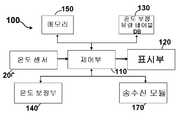
도 2는 본 발명 차량의 연료탱크 실시간 온도 및 연료 측정 시스템 구성도이다. 상기도 2에서 본 발명 차량의 연료탱크 실시간 온도 및 연료 측정 시스템은 차량에 설치되고 주유 관의 온도 센서로부터 온도 정보를 수신하여 저장하고, 연료탱크 측정장치 단말기로부터 주기적으로 잔유 연료량 및 잔유 온도 정보를 수신하여 저장하며, 상기 온도 센서로부터 수신되는 온도 정보, 연료 탱크 측정 장치 단말기로부터 수신되는 잔유 연료량 정보를 섭씨 15℃로 보정한 연료 탱크의 총 연료량 정보, 잔유 온도 정보를 표출하는 차량 계기부(100)와, 주유관에 설치되고 온도 정보를 생성하여 디지털 신호로 변환하여 차량 계기부로 전송하는 온도 센서(200) 및 차량 내의 연료 탱크에 현재 저장되어 있는 잔유 연료량과 잔유 온도를 측정하고 주기적으로 차량 계기부로 전송하는 연료탱크 측정장치 단말기(550)로 구성된 것을 특징으로 하는 것이다.
2 is a fuel tank real time temperature and fuel measurement system configuration diagram of the vehicle of the present invention. 2, the fuel tank real-time temperature and fuel measurement system of the vehicle of the present invention is installed in a vehicle and receives and stores temperature information from a temperature sensor of a fuel supply pipe, and periodically receives residual fuel amount and residual temperature information from the fuel tank measurement device terminal And displays the remaining fuel amount information and remaining temperature information of the fuel tank, which is obtained by correcting the temperature information received from the temperature sensor, the residual fuel amount information received from the fuel tank measuring device terminal to 15 ° C, A
도 3은 본 발명에 적용되는 차량 계기부 상세 구성도이다. 상기도 3에서 본 발명에 적용되는 차량 계기부(100)는 차량의 주유구와 연료 탱크를 연결하는 주유 관에 설치되는 온도 센서로부터 온도 정보를 수신받아 저장하며, 연료탱크 측정장치 단말기로부터 잔유 연료량 및 잔유 온도 정보를 주기적으로 수신하여 저장하며, 온도 센서의 온도 정보, 주유 전 잔유 연료량 정보 및 주유 전 잔유 연료 온도 정보, 주유 후 총 연료 량 정보, 주유 후 온도 정보, 주유 후 보정된 총 연료량 정보를 표시부를 통하여 표출하도록 제어하며 상기 수신된 주유 후 잔유 온도 정보와 주유 후 잔유 연료 량 정보를 기초로 하여 온도 보정부로 하여금 온도 보정 유량 테이블 DB를 이용하여 온도 보정(섭씨 15℃로 온도 보정)을 통하여 주유 후 총 연료량을 산정하도록 제어하는 제어부(110)와, 연료 탱크에 설치되고 연료 탱크의 실시간 연료량 및 실시간 온도를 측정하며 상기 실시간 연료량 정보 및 실시간 온도 정보를 전송하는 연료탱크 측정장치 단말기로부터 잔유 연료량 정보 및 잔유 온도 정보를 수신하기 위한 송수신 모듈(170)과, 휘발유, 경우 등에 관한 온도 및 밀도에 따른 보정 계수를 저장하고 있는 온도 보정 유량 테이블 DB(130)와, 주유 후의 잔유량 온도정보와 주유 후의 총 연료량 정보가 수신되면 상기 온도 보정 유량 테이블 DB를 기초로 주유 후의 총 연료 량을 재산정하고 메모리에 저장하도록 하는 온도 보정부(140)와, 온도 센서 및 연료탱크 측정장치 단말기로부터 수신되는 온도 정보, 주유 후의 총 연료량 정보, 주유 후의 연료 탱크의 잔유 온도 정보 및 온도 보정부에서 재산정한 주유 후의 총 연료량 정보를 저장하는 메모리(150)와, 온도 센서로부터 수신되는 온도 정보, 주유 전 보정된 총 연료량 정보, 주유 전 연료 탱크의 잔유 온도 정보, 주유 후의 보정된 총 연료량 정보 및 주유 후의 연료 탱크의 잔유 온도 정보를 표출할 수 있는 표시부(120)로 구성된 것을 특징으로 하는 것이다. 상기에서 온도 보정에 사용되는 연료 량의 밀도는 온도 보정 유량 테이블의 밀도의 평균값을 이용하여 온도 보정을 할 수 있는 것이다. 상기에서 밀도는 휘발유, 항공유, 등유 경유에 따라 상이하고 휘발유는 0.710 ~ 0.750, 항공유는 0.780 ~ 0.800, 등유는 0.790 ~ 0.815, 경유는 0.815 ~ 0.855 범위이다. 또한 상기 온도 보정 유량 테이블은 연료의 온도 보정을 위하여 공지되어 있는 테이블 정보이다.
3 is a detailed configuration diagram of a vehicle instrument applied to the present invention. 3, the
도 4는 본 발명에 적용되는 샘플 유량부 구성도이다. 상기도 4에서 본 발명에 적용되는 샘플 유량부(250)는 차량 주유구와 주유 탱크를 연결하는 주유 관(251)에 설치되는 것으로 주유 관 내측으로 형성되는 고깔 모양의 것으로 주유하는 연료가 용이하게 몸체부로 유입되도록 하는 고깔 모양의 사선부(253)와, 상기 사선부에 연결되며 주유하는 유체가 몸체부로 유입되어 몸체부(259)에 유입된 유체가 몸체부 내에서 서서히 상승하도록 몸체부 하부 일측에 구성되는 유입관(255)과, 상기 유입관과 비교하여 1/8 ~ 1/10의 비율로 내경이 적어 몸체부 내의 연료가 서서히 유출되도록 하며 몸체 내측의 하단 유입관 반대 측면에 설치되어 연료를 다시 주유관으로 흐르도록 하는 유출관(257)으로 구성 설치되는 것이고, 상기 유체가 몸체부에 유입된 후 안정화 과정을 거쳐 온도를 센싱하고 온도 정보를 차량 계기부로 전송하는 온도 센서(261) 및 온도 센서 전송부(263)로 구성된 것을 특징으로 하는 것이다. 상기와 같이 구성된 샘플 유량부를 통하여 온도 정보를 센싱하면 정확한 연료 온도 정보를 얻을 수 있고 이에 따라서 온도 보정된 주유 량 정보도 정확히 구할 수 있는 것이다. 또한 본원출원은 상기 샘플 유량부 구성없이 바로 주유 관에 온도 센서를 설치하여 온도 정보를 수신할 수도 있는 것이다.
4 is a block diagram of a sample flow rate portion applied to the present invention. 4, the sample
도 5는 온도 보정 유량 테이블 DB이다. 상기도 5에서 온도 보정 유량 테이블 DB는 부피 측정시의 연료 온도, 15℃의 밀도와 부피 환산 계수(보정 계수)가 샘플로 나타내고 있는 것이다. 상기에서 밀도는 연료를 공급하는 회사로부터 주어질 수 있으며 상기 밀도 정보는 주유펌프 단말기가 입력받고 상기 주유 펌프 단말기가 주유 량 정보와 함께 차량 계기부로 전송하여 온도 보정에 이용될 수 있는 것이다.
5 is a temperature correction flow rate table DB. In FIG. 5, the temperature correction flow rate table DB shows the fuel temperature at the time of volume measurement, the density at 15 DEG C, and the volume conversion coefficient (correction coefficient) as samples. In this case, the density may be given from a company that supplies fuel, and the density information may be input to the gas pump terminal, and the gas pump terminal may transmit the gasoline amount information to the vehicle instrument unit to be used for temperature correction.
100: 차량 계기부, 110 : 제어부,
120 : 표시부, 130 : 온도 보정 유량 테이블 DB,
140 : 온도 보정부, 200 : 온도 센서,100: vehicle instrument part, 110: control part,
120: display section, 130: temperature correction flow rate table DB,
140: temperature correction unit, 200: temperature sensor,
Claims (4)
Translated fromKorean상기 차량 연료탱크 실시간 온도 및 연료 측정 시스템은,
차량의 주유구와 연료 탱크를 연결하는 주유 관에 설치되고 주유 중의 온도를 센싱하고 디지털 신호로 변환하여 제어부로 전송하는 온도 센서(200)와;
상기 주유 관에 설치된 온도 센서(200)로부터 온도 정보를 수신하여 저장하고, 연료탱크 측정장치 단말기로부터 주기적으로 잔유 연료량 및 잔유 온도 정보를 수신하여 저장하며, 상기 온도 센서(200)로부터 수신되는 온도 정보, 연료 탱크 측정 장치 단말기로부터 수신되는 잔유 연료량 정보를 섭씨 15℃로 보정한 연료 탱크의 총 연료량 정보, 잔유 온도 정보를 표출하는 것으로 차량의 주유구와 연료 탱크를 연결하는 주유 관에 설치되는 온도 센서로부터 온도 정보를 수신받아 저장하고, 연료탱크 측정장치 단말기로부터 잔유 연료량 정보 및 잔유 온도 정보를 주기적으로 수신하여 저장하며, 온도 센서의 온도 정보, 주유 전 잔유 연료량 정보 및 주유 전 잔유 연료 온도 정보, 주유 후 총 연료 량 정보, 주유 후 온도 정보, 주유 후 보정된 총 연료량 정보를 표시부를 통하여 표출하도록 제어하며 상기 수신된 주유 후 잔유 온도 정보와 주유 후 잔유 연료 량 정보를 기초로 하여 온도 보정부로 하여금 온도 보정 유량 테이블 DB를 이용하여 섭씨 15℃로 온도 보정을 통하여 주유 후 총 연료량을 산정하도록 제어하는 제어부(110)와 연료 탱크에 설치되고 연료 탱크의 실시간 잔유 연료량 및 실시간 잔유 온도를 측정하며 상기 실시간 잔유 연료량 정보 및 실시간 잔유 온도 정보를 전송하는 연료탱크 측정장치 단말기로부터 잔유 연료량 정보 및 잔유 온도 정보를 수신하기 위한 송수신 모듈(170)과 휘발유, 경우에 관한 온도 및 밀도에 따른 보정 계수를 저장하고 있는 온도 보정 유량 테이블 DB(130)와 주유 후의 잔유량 온도정보와 주유 후의 총 연료량 정보가 수신되면 상기 온도 보정 유량 테이블 DB를 기초로 주유 후의 총 연료 량을 재산정하고 메모리에 저장하도록 하는 온도 보정부(140)와 온도 센서 및 연료탱크 측정장치 단말기로부터 수신되는 온도 정보, 주유 후의 총 연료량 정보, 주유 후의 연료 탱크의 잔유 온도 정보 및 온도 보정부에서 재산정한 주유 후의 총 연료량 정보를 저장하는 메모리(150) 및 온도 센서로부터 수신되는 온도 정보, 주유 전 잔유 연료량 정보, 주유 전 연료 탱크의 잔유 온도 정보, 주유 후의 보정된 총 연료량 정보 및 주유 후의 연료 탱크의 잔유 온도 정보를 표출할 수 있는 표시부(120)로 구성된 차량 계기부(100);
및 차량 내의 연료 탱크에 현재 저장되어 있는 잔유 연료량과 잔유 온도를 측정하고 주기적으로 차량 계기부로 전송하는 연료탱크 측정장치 단말기(550)로 구성된 것을 특징으로 하는 차량 연료탱크 실시간 온도 및 연료 측정 시스템.
A vehicle fuel tank real-time temperature and fuel measurement system,
The vehicle fuel tank real-time temperature and fuel measurement system includes:
A temperature sensor (200) installed in a fuel supply line connecting a fuel supply port of a vehicle and a fuel tank, sensing a temperature of the fuel oil, converting the temperature into a digital signal, and transmitting the digital signal to a control unit;
Receives and stores temperature information from a temperature sensor (200) installed in the main pipe, periodically receives and stores residual fuel amount and residual temperature information from a fuel tank measuring device terminal, and stores temperature information received from the temperature sensor A total fuel amount information of the fuel tank corrected with the residual fuel amount information received from the fuel tank measuring device terminal by 15 ° C, and a residual temperature information, which is provided from a temperature sensor installed in the fuel supply pipe connecting the fuel supply port of the vehicle and the fuel tank Temperature information and periodically receives and stores residual fuel amount information and residual temperature information from the fuel tank measuring apparatus terminal, and stores temperature information of the temperature sensor, remaining fuel amount information before pouring, remaining fuel temperature information before pouring, Total fuel amount information, post-injection temperature information, and total fuel amount information corrected after injection The control unit controls the temperature correction unit based on the received post-mainstream residual temperature information and the remaining fuel amount information after the main feed to the temperature correction table by using the temperature correction flow rate table DB, A fuel tank measuring device installed in the fuel tank for measuring a real time residual fuel amount and a real time residual temperature of the fuel tank and transmitting the real time residual fuel amount information and real time residual temperature information, A temperature correction flow rate table DB 130 for storing correction coefficients according to the temperature and density of gasoline and the case, a temperature correction flow rate table DB 130 for storing the correction value according to the temperature and density of the case, When the information is received, based on the temperature correction flow rate table DB, The temperature information received from the temperature sensor and the fuel tank measuring device terminal, the total fuel amount information after fueling, the remaining temperature information of the fuel tank after fueling, and the temperature information A memory 150 for storing the total fuel amount information after the refueling determined by the government, temperature information received from the temperature sensor, residual fuel amount information before pre-injection, remaining temperature information of the pre-mainstream fuel tank, corrected total amount of fuel after injection, A vehicle instrument unit (100) comprising a display unit (120) capable of displaying residual temperature information of a fuel tank;
And a fuel tank measuring apparatus terminal (550) for measuring and periodically transmitting the residual fuel amount and residual temperature currently stored in the fuel tank in the vehicle to the vehicle instrument unit.
상기 온도 센서는,
차량 주유구와 주유 탱크를 연결하는 주유 관(251)에 설치되는 것으로 주유 관 내측으로 형성되는 고깔 모양의 것으로 주유하는 연료가 용이하게 몸체부로 유입되도록 하는 고깔 모양의 사선부(253)와 상기 사선부에 연결되며 주유하는 연료가 몸체부로 유입되어 몸체부(259)에 유입된 연료가 몸체부 내에서 서서히 상승하도록 몸체부 하부 일측에 구성되는 유입관(255) 및 상기 유입관과 비교하여 1/8 ~ 1/10의 비율로 내경이 적어 몸체부 내의 연료가 서서히 유출되도록 하며 몸체 내측의 하단 유입관 반대 측면에 설치되어 연료를 다시 주유 관으로 흐르도록 하는 유출관(257)으로 구성된 샘플 유량부(250)에 설치되는 것을 특징으로 하는 차량 연료탱크 실시간 온도 및 연료 측정 시스템.
3. The method of claim 2,
Wherein the temperature sensor comprises:
And is formed in a gas supply pipe (251) connecting the vehicle fuel supply port and the fuel supply tank, and has a conical shape formed inside the gas supply pipe, and has a chevron shaped cheek part (253) for allowing fuel to be injected into the body easily, And an inlet pipe 255 connected to the lower portion of the body so that the fuel injected into the body portion 251 flows into the body portion 259 gradually so as to rise gradually in the body portion, And a drain pipe (257) for allowing the fuel in the body to gradually flow out at a ratio of about 1/10 to the fuel pipe (257) installed on the side opposite to the lower inlet pipe on the inside of the body, 250). ≪ / RTI >
Priority Applications (1)
| Application Number | Priority Date | Filing Date | Title |
|---|---|---|---|
| KR1020150047416AKR101663541B1 (en) | 2015-04-03 | 2015-04-03 | Temperature and Revised Volume Measuring System of Fuel Tank at Vehicle |
Applications Claiming Priority (1)
| Application Number | Priority Date | Filing Date | Title |
|---|---|---|---|
| KR1020150047416AKR101663541B1 (en) | 2015-04-03 | 2015-04-03 | Temperature and Revised Volume Measuring System of Fuel Tank at Vehicle |
Publications (1)
| Publication Number | Publication Date |
|---|---|
| KR101663541B1true KR101663541B1 (en) | 2016-10-07 |
Family
ID=57145301
Family Applications (1)
| Application Number | Title | Priority Date | Filing Date |
|---|---|---|---|
| KR1020150047416AExpired - Fee RelatedKR101663541B1 (en) | 2015-04-03 | 2015-04-03 | Temperature and Revised Volume Measuring System of Fuel Tank at Vehicle |
Country Status (1)
| Country | Link |
|---|---|
| KR (1) | KR101663541B1 (en) |
Cited By (1)
| Publication number | Priority date | Publication date | Assignee | Title |
|---|---|---|---|---|
| KR102775923B1 (en)* | 2024-04-16 | 2025-03-06 | 한화에어로스페이스 주식회사 | Method for bunkering monitoring, bunkering control method using the same and bunkering monitoring apparatus |
Citations (4)
| Publication number | Priority date | Publication date | Assignee | Title |
|---|---|---|---|---|
| KR20080088285A (en)* | 2007-03-29 | 2008-10-02 | 전북대학교산학협력단 | Gasoline Inspection Device for Vehicle Installation |
| KR20120017942A (en)* | 2010-08-20 | 2012-02-29 | 재단법인 포항산업과학연구원 | Fuel indicator detection device and method |
| KR20130137259A (en)* | 2012-06-07 | 2013-12-17 | 현대자동차주식회사 | Reformulated fuel detecting apparatus of vehicle |
| KR101479072B1 (en)* | 2013-10-21 | 2015-01-07 | 신흥콘트롤(주) | Fuel level checking apparatus of automobile fuel tank |
- 2015
- 2015-04-03KRKR1020150047416Apatent/KR101663541B1/ennot_activeExpired - Fee Related
Patent Citations (4)
| Publication number | Priority date | Publication date | Assignee | Title |
|---|---|---|---|---|
| KR20080088285A (en)* | 2007-03-29 | 2008-10-02 | 전북대학교산학협력단 | Gasoline Inspection Device for Vehicle Installation |
| KR20120017942A (en)* | 2010-08-20 | 2012-02-29 | 재단법인 포항산업과학연구원 | Fuel indicator detection device and method |
| KR20130137259A (en)* | 2012-06-07 | 2013-12-17 | 현대자동차주식회사 | Reformulated fuel detecting apparatus of vehicle |
| KR101479072B1 (en)* | 2013-10-21 | 2015-01-07 | 신흥콘트롤(주) | Fuel level checking apparatus of automobile fuel tank |
Cited By (1)
| Publication number | Priority date | Publication date | Assignee | Title |
|---|---|---|---|---|
| KR102775923B1 (en)* | 2024-04-16 | 2025-03-06 | 한화에어로스페이스 주식회사 | Method for bunkering monitoring, bunkering control method using the same and bunkering monitoring apparatus |
Similar Documents
| Publication | Publication Date | Title |
|---|---|---|
| CA2358583C (en) | A method for filling a vehicle fuel tank with gas | |
| US10502649B1 (en) | Apparatus and method for testing compressed gas dispensing stations | |
| KR102163603B1 (en) | Hydrogen gas dispenser inspection device | |
| CN107462306B (en) | An automatic calibration method of a fuel dispenser automatic calibration device | |
| US20130014854A1 (en) | Fuel gas station, fuel gas filling system, and fuel gas supplying method | |
| JP6473290B2 (en) | Metering system and method for cryogenic liquids | |
| CN204330095U (en) | Supercritical CO 2flowmeter prover | |
| KR101639033B1 (en) | Temperature and Volume Measuring System of Fuel Tank at Vehicle by using Gas Pump | |
| KR101663541B1 (en) | Temperature and Revised Volume Measuring System of Fuel Tank at Vehicle | |
| US20120253706A1 (en) | System and method for monitoring liquid level in containers/reservoirs | |
| CN104568082A (en) | Supercritical CO2 flowmeter calibration device and calibration method thereof | |
| CN104089687A (en) | Online calibration device and method for LNG filling machine | |
| WO2011112110A2 (en) | Module for filling bottles with liquid propane-butane mixture and compounds and process of handling | |
| AU2017326740B2 (en) | Tank testing apparatus and method | |
| CN213021796U (en) | Be used for car oil feeding system oil pump to mark level sensor | |
| AU2001290187B2 (en) | Method and apparatus for determining the volume of liquid in a reservoir | |
| CN104864944B (en) | Fuel tank for automobile calibration system and method | |
| KR20170024694A (en) | Vehicle Loaded with Unexposed Inspection Equipment and Inspection Method of Injected Fuel Amount | |
| KR20120079917A (en) | Measurement system for feul capacity | |
| KR20210074950A (en) | oil flow measurement instrument on automonile | |
| EP3620711B1 (en) | Apparatus and method for testing compressed gas dispensing stations | |
| AU2001290187A1 (en) | Method and apparatus for determining the volume of liquid in a reservoir | |
| KR101251721B1 (en) | Measurement system for fuel capacity | |
| KR200352139Y1 (en) | Automatic Temperature Compensator | |
| US11268656B2 (en) | Calculation of remaining usage time of a gas cylinder |
Legal Events
| Date | Code | Title | Description |
|---|---|---|---|
| PA0109 | Patent application | St.27 status event code:A-0-1-A10-A12-nap-PA0109 | |
| PA0201 | Request for examination | St.27 status event code:A-1-2-D10-D11-exm-PA0201 | |
| D13-X000 | Search requested | St.27 status event code:A-1-2-D10-D13-srh-X000 | |
| D14-X000 | Search report completed | St.27 status event code:A-1-2-D10-D14-srh-X000 | |
| PE0902 | Notice of grounds for rejection | St.27 status event code:A-1-2-D10-D21-exm-PE0902 | |
| E13-X000 | Pre-grant limitation requested | St.27 status event code:A-2-3-E10-E13-lim-X000 | |
| P11-X000 | Amendment of application requested | St.27 status event code:A-2-2-P10-P11-nap-X000 | |
| P13-X000 | Application amended | St.27 status event code:A-2-2-P10-P13-nap-X000 | |
| PE0701 | Decision of registration | St.27 status event code:A-1-2-D10-D22-exm-PE0701 | |
| GRNT | Written decision to grant | ||
| PR0701 | Registration of establishment | St.27 status event code:A-2-4-F10-F11-exm-PR0701 | |
| PR1002 | Payment of registration fee | St.27 status event code:A-2-2-U10-U11-oth-PR1002 Fee payment year number:1 | |
| PG1601 | Publication of registration | St.27 status event code:A-4-4-Q10-Q13-nap-PG1601 | |
| P22-X000 | Classification modified | St.27 status event code:A-4-4-P10-P22-nap-X000 | |
| FPAY | Annual fee payment | Payment date:20190711 Year of fee payment:4 | |
| PR1001 | Payment of annual fee | St.27 status event code:A-4-4-U10-U11-oth-PR1001 Fee payment year number:4 | |
| PR1001 | Payment of annual fee | St.27 status event code:A-4-4-U10-U11-oth-PR1001 Fee payment year number:5 | |
| PR1001 | Payment of annual fee | St.27 status event code:A-4-4-U10-U11-oth-PR1001 Fee payment year number:6 | |
| P22-X000 | Classification modified | St.27 status event code:A-4-4-P10-P22-nap-X000 | |
| PC1903 | Unpaid annual fee | St.27 status event code:A-4-4-U10-U13-oth-PC1903 Not in force date:20221001 Payment event data comment text:Termination Category : DEFAULT_OF_REGISTRATION_FEE | |
| PC1903 | Unpaid annual fee | St.27 status event code:N-4-6-H10-H13-oth-PC1903 Ip right cessation event data comment text:Termination Category : DEFAULT_OF_REGISTRATION_FEE Not in force date:20221001 | |
| P22-X000 | Classification modified | St.27 status event code:A-4-4-P10-P22-nap-X000 |