KR101660393B1 - Evaporation source and Apparatus for deposition having the same - Google Patents
Evaporation source and Apparatus for deposition having the sameDownload PDFInfo
- Publication number
- KR101660393B1 KR101660393B1KR1020150092901AKR20150092901AKR101660393B1KR 101660393 B1KR101660393 B1KR 101660393B1KR 1020150092901 AKR1020150092901 AKR 1020150092901AKR 20150092901 AKR20150092901 AKR 20150092901AKR 101660393 B1KR101660393 B1KR 101660393B1
- Authority
- KR
- South Korea
- Prior art keywords
- tube
- substrate
- injection nozzle
- nozzle
- evaporation
- Prior art date
- Legal status (The legal status is an assumption and is not a legal conclusion. Google has not performed a legal analysis and makes no representation as to the accuracy of the status listed.)
- Active
Links
Images

Classifications
- C—CHEMISTRY; METALLURGY
- C23—COATING METALLIC MATERIAL; COATING MATERIAL WITH METALLIC MATERIAL; CHEMICAL SURFACE TREATMENT; DIFFUSION TREATMENT OF METALLIC MATERIAL; COATING BY VACUUM EVAPORATION, BY SPUTTERING, BY ION IMPLANTATION OR BY CHEMICAL VAPOUR DEPOSITION, IN GENERAL; INHIBITING CORROSION OF METALLIC MATERIAL OR INCRUSTATION IN GENERAL
- C23C—COATING METALLIC MATERIAL; COATING MATERIAL WITH METALLIC MATERIAL; SURFACE TREATMENT OF METALLIC MATERIAL BY DIFFUSION INTO THE SURFACE, BY CHEMICAL CONVERSION OR SUBSTITUTION; COATING BY VACUUM EVAPORATION, BY SPUTTERING, BY ION IMPLANTATION OR BY CHEMICAL VAPOUR DEPOSITION, IN GENERAL
- C23C14/00—Coating by vacuum evaporation, by sputtering or by ion implantation of the coating forming material
- C23C14/22—Coating by vacuum evaporation, by sputtering or by ion implantation of the coating forming material characterised by the process of coating
- C23C14/24—Vacuum evaporation
- C—CHEMISTRY; METALLURGY
- C23—COATING METALLIC MATERIAL; COATING MATERIAL WITH METALLIC MATERIAL; CHEMICAL SURFACE TREATMENT; DIFFUSION TREATMENT OF METALLIC MATERIAL; COATING BY VACUUM EVAPORATION, BY SPUTTERING, BY ION IMPLANTATION OR BY CHEMICAL VAPOUR DEPOSITION, IN GENERAL; INHIBITING CORROSION OF METALLIC MATERIAL OR INCRUSTATION IN GENERAL
- C23C—COATING METALLIC MATERIAL; COATING MATERIAL WITH METALLIC MATERIAL; SURFACE TREATMENT OF METALLIC MATERIAL BY DIFFUSION INTO THE SURFACE, BY CHEMICAL CONVERSION OR SUBSTITUTION; COATING BY VACUUM EVAPORATION, BY SPUTTERING, BY ION IMPLANTATION OR BY CHEMICAL VAPOUR DEPOSITION, IN GENERAL
- C23C14/00—Coating by vacuum evaporation, by sputtering or by ion implantation of the coating forming material
- C23C14/06—Coating by vacuum evaporation, by sputtering or by ion implantation of the coating forming material characterised by the coating material
- C23C14/12—Organic material
- C—CHEMISTRY; METALLURGY
- C23—COATING METALLIC MATERIAL; COATING MATERIAL WITH METALLIC MATERIAL; CHEMICAL SURFACE TREATMENT; DIFFUSION TREATMENT OF METALLIC MATERIAL; COATING BY VACUUM EVAPORATION, BY SPUTTERING, BY ION IMPLANTATION OR BY CHEMICAL VAPOUR DEPOSITION, IN GENERAL; INHIBITING CORROSION OF METALLIC MATERIAL OR INCRUSTATION IN GENERAL
- C23C—COATING METALLIC MATERIAL; COATING MATERIAL WITH METALLIC MATERIAL; SURFACE TREATMENT OF METALLIC MATERIAL BY DIFFUSION INTO THE SURFACE, BY CHEMICAL CONVERSION OR SUBSTITUTION; COATING BY VACUUM EVAPORATION, BY SPUTTERING, BY ION IMPLANTATION OR BY CHEMICAL VAPOUR DEPOSITION, IN GENERAL
- C23C14/00—Coating by vacuum evaporation, by sputtering or by ion implantation of the coating forming material
- C23C14/22—Coating by vacuum evaporation, by sputtering or by ion implantation of the coating forming material characterised by the process of coating
- C23C14/24—Vacuum evaporation
- C23C14/243—Crucibles for source material
- C—CHEMISTRY; METALLURGY
- C23—COATING METALLIC MATERIAL; COATING MATERIAL WITH METALLIC MATERIAL; CHEMICAL SURFACE TREATMENT; DIFFUSION TREATMENT OF METALLIC MATERIAL; COATING BY VACUUM EVAPORATION, BY SPUTTERING, BY ION IMPLANTATION OR BY CHEMICAL VAPOUR DEPOSITION, IN GENERAL; INHIBITING CORROSION OF METALLIC MATERIAL OR INCRUSTATION IN GENERAL
- C23C—COATING METALLIC MATERIAL; COATING MATERIAL WITH METALLIC MATERIAL; SURFACE TREATMENT OF METALLIC MATERIAL BY DIFFUSION INTO THE SURFACE, BY CHEMICAL CONVERSION OR SUBSTITUTION; COATING BY VACUUM EVAPORATION, BY SPUTTERING, BY ION IMPLANTATION OR BY CHEMICAL VAPOUR DEPOSITION, IN GENERAL
- C23C14/00—Coating by vacuum evaporation, by sputtering or by ion implantation of the coating forming material
- C23C14/22—Coating by vacuum evaporation, by sputtering or by ion implantation of the coating forming material characterised by the process of coating
- C23C14/24—Vacuum evaporation
- C23C14/26—Vacuum evaporation by resistance or inductive heating of the source
Landscapes
- Chemical & Material Sciences (AREA)
- Chemical Kinetics & Catalysis (AREA)
- Engineering & Computer Science (AREA)
- Materials Engineering (AREA)
- Mechanical Engineering (AREA)
- Metallurgy (AREA)
- Organic Chemistry (AREA)
- Physical Vapour Deposition (AREA)
Abstract
Translated fromKorean
Description
Translated fromKorean본 발명은 증발원 및 이를 구비한 증착장치에 관한 것이다. 보다 상세하게는, 가열된 증발원의 열이 기판 또는 마스크에 전달되는 것을 억제하여 균일한 박막을 형성할 수 있는 증발원 및 이를 구비한 증착장치에 관한 것이다.The present invention relates to an evaporation source and a deposition apparatus having the evaporation source. More particularly, the present invention relates to an evaporation source capable of forming a uniform thin film by inhibiting the heat of a heated evaporation source from being transferred to a substrate or a mask, and a deposition apparatus having the evaporation source.
유기 전계 발광소자(Organic Light Emitting Diodes: OLED)는 형광성 유기화합물에 전류가 흐르면 빛을 내는 전계 발광현상을 이용하는 스스로 빛을 내는 자발광소자로서, 비발광소자에 빛을 가하기 위한 백라이트가 필요하지 않기 때문에 경량이고 박형의 평판표시장치를 제조할 수 있다.BACKGROUND ART Organic light emitting diodes (OLEDs) are self-light emitting devices that emit light by using an electroluminescent phenomenon that emits light when a current flows through a fluorescent organic compound. A backlight for applying light to a non- Therefore, a lightweight thin flat panel display device can be manufactured.
유기 전계 발광 소자는, 애노드 및 캐소드 전극을 제외한 나머지 구성층인 정공주입층, 정공수송층, 발광층, 전자수송층 및 전자주입층 등이 유기 박막으로 되어 있고, 이러한 유기 박막은 진공열증착방법으로 기판 상에 증착될 수 있다.The organic electroluminescent device comprises an organic thin film such as a hole injecting layer, a hole transporting layer, a light emitting layer, an electron transporting layer, and an electron injecting layer which are the remaining constituent layers except for the anode and the cathode. Lt; / RTI >
진공열증착방법은 진공의 챔버 내에 기판을 배치하고, 일정 패턴이 형성된 쉐도우 마스크(shadow mask)를 기판에 정렬시킨 후, 증발물질이 담겨 있는 증발원에 열을 가하여 증발원에서 증발되는 증발입자가 기판 상에 증착되는 방식으로 이루어진다.In the vacuum thermal deposition method, a substrate is placed in a vacuum chamber, a shadow mask having a predetermined pattern is aligned on a substrate, heat is applied to an evaporation source containing the evaporation material, As shown in FIG.
그런데, 증발원의 내부에 수용되는 증발물질을 증발시키기 위하여 가열부가 높은 온도로 증발원을 가열하게 되는데, 이때 발생되는 고온의 열이 증발원의 상단에 위치한 기판 또는 마스크에 전달되어 불균일한 박막이 형성되는 문제점이 있다.However, in order to evaporate the evaporation material accommodated in the evaporation source, the heating unit heats the evaporation source at a high temperature. The heat generated at this time is transferred to the substrate or mask located at the upper end of the evaporation source, .
본 발명은 가열된 증발원의 열이 기판 또는 마스크에 전달되는 것을 억제하여 균일한 박막을 형성할 수 있는 증발원 및 이를 구비한 증착장치를 제공하는 것이다.The present invention provides an evaporation source capable of forming a uniform thin film by inhibiting the heat of a heated evaporation source from being transferred to a substrate or a mask, and a deposition apparatus having the evaporation source.
본 발명의 일 측면에 따르면, 이송관과, 상기 이송관과 연통되도록 상기 이송관의 일단에 횡방향으로 결합되는 확산관과, 상기 이송관에 대하여 방사상으로 돌출되도록 상기 확산관의 길이 방향을 따라 형성되는 복수의 분사 노즐을 포함하는 노즐부와; 상기 이송관의 타단에 결합되며, 내부에 증발물질이 수용되는 용기 형상의 도가니와; 상기 분사 노즐의 외주를 커버하도록 상기 분사 노즐이 삽입되는 방열 튜브가 구비되며, 상기 확산관의 상부를 커버하는 방열판을 포함하는, 증발원이 제공된다.According to an aspect of the present invention, there is provided a transfer tube, including: a transfer tube; a diffusion tube horizontally coupled to one end of the transfer tube to communicate with the transfer tube; A nozzle unit including a plurality of injection nozzles to be formed; A container-shaped crucible coupled to the other end of the transfer pipe and having an evaporation material therein; And a heat radiation plate for covering the outer periphery of the injection nozzle and including a heat radiation tube into which the injection nozzle is inserted, the heat radiation plate covering an upper portion of the diffusion tube.
상기 분사 노즐의 단부와 상기 방열 튜브의 단부는 동일선 상에 위치할 수 있다.The end of the injection nozzle and the end of the heat radiation tube may be located on the same line.
상기 이송관은 상기 확산관의 길이 방향을 따라 서로 이격되어 복수 개로 결합되며, 상기 분사 노즐은 상기 이송관 각각을 중심으로 방사상으로 돌출되어 형성될 수 있다.The transfer tubes may be spaced apart from each other along the longitudinal direction of the diffusion tube, and the injection nozzles may protrude radially around the transfer tubes.
상기 분사 노즐에 결합되며, 서로 다른 노즐 크기를 갖는 복수의 노즐캡을 더 포함할 수 있다.And a plurality of nozzle caps coupled to the injection nozzles and having different nozzle sizes.
기판에 증발입자를 증착하는 증착장치로서, 진공 챔버와; 상기 진공 챔버 내부에 배치되며, 상기 기판이 안착되는 기판 안착부와; 상기 기판에 대향하여 상기 증발입자를 분출하는 상기 증발원을 포함하는, 증착장치가 제공된다.A deposition apparatus for depositing evaporation particles on a substrate, comprising: a vacuum chamber; A substrate mounting part disposed inside the vacuum chamber and on which the substrate is mounted; And the evaporation source for ejecting the evaporation particles against the substrate.
상기 확산관의 길이는 상기 기판의 폭 보다 작게 형성될 수 있다.The length of the diffusion tube may be smaller than the width of the substrate.
본 발명의 실시예에 따르면, 가열된 증발원의 열이 기판 또는 마스크에 전달되는 것을 억제하여 균일한 박막을 형성할 수 있다.According to the embodiment of the present invention, it is possible to prevent the heat of the heated evaporation source from being transferred to the substrate or the mask, thereby forming a uniform thin film.
도 1은 본 발명의 일 실시예에 따른 증발원의 단면도.
도 2는 본 발명의 일 실시예에 따른 증발원을 구비한 증착장치의 단면도.1 is a cross-sectional view of an evaporation source according to an embodiment of the present invention;
2 is a sectional view of a deposition apparatus having an evaporation source according to an embodiment of the present invention;
본 발명은 다양한 변환을 가할 수 있고 여러 가지 실시예를 가질 수 있는 바, 특정 실시예들을 도면에 예시하고 상세한 설명에 상세하게 설명하고자 한다. 그러나, 이는 본 발명을 특정한 실시 형태에 대해 한정하려는 것이 아니며, 본 발명의 사상 및 기술 범위에 포함되는 모든 변환, 균등물 내지 대체물을 포함하는 것으로 이해되어야 한다. 본 발명을 설명함에 있어서 관련된 공지 기술에 대한 구체적인 설명이 본 발명의 요지를 흐릴 수 있다고 판단되는 경우 그 상세한 설명을 생략한다.BRIEF DESCRIPTION OF THE DRAWINGS The present invention is capable of various modifications and various embodiments, and specific embodiments are illustrated in the drawings and described in detail in the detailed description. It is to be understood, however, that the invention is not to be limited to the specific embodiments, but includes all modifications, equivalents, and alternatives falling within the spirit and scope of the invention. DETAILED DESCRIPTION OF THE PREFERRED EMBODIMENTS Hereinafter, the present invention will be described in detail with reference to the accompanying drawings.
이하, 본 발명에 따른 증발원 및 이를 구비한 증착장치의 실시예를 첨부도면을 참조하여 상세히 설명하기로 하며, 첨부 도면을 참조하여 설명함에 있어, 동일하거나 대응하는 구성 요소는 동일한 도면번호를 부여하고 이에 대한 중복되는 설명은 생략하기로 한다.DETAILED DESCRIPTION OF THE PREFERRED EMBODIMENT Hereinafter, embodiments of an evaporation source and a deposition apparatus having the same according to the present invention will be described in detail with reference to the accompanying drawings, wherein like reference numerals designate like or corresponding components A duplicate description thereof will be omitted.
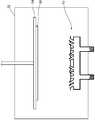
도 1은 본 발명의 일 실시예에 따른 증발원(10)의 단면도이다. 도 1에는 증발원(10), 이송관(12), 확산관(14), 분사 노즐(16), 노즐부(18), 도가니(20), 증발물질(22), 방열 튜브(24), 방열판(26), 노즐캡(28)이 도시되어 있다.1 is a cross-sectional view of an
본 실시예에 따른 증발원(10)은, 이송관(12)과, 이송관(12)과 연통되도록 이송관(12)의 일단에 횡방향으로 결합되는 확산관(14)과, 이송관(12)에 대하여 방사상으로 돌출되도록 확산관(14)의 길이 방향을 따라 형성되는 복수의 분사 노즐(16)을 포함하는 노즐부(18)와; 이송관(12)의 타단에 결합되며, 내부에 증발물질(22)이 수용되는 용기 형상의 도가니(20)와; 분사 노즐(16)의 외주를 커버하도록 분사 노즐(16)이 삽입되는 방열 튜브(24)가 구비되며, 확산관(14)의 상부를 커버하는 방열판(26)을 포함한다.The
이송관(12)은, 길이 방향으로 관통부가 형성된 튜브 형태로서, 하단이 후술한 도가니(20)의 개방된 상단과 연통되도록 결합될 수 있다. 후술할 도가니(20)에서 분출되는 증발입자는 이송관(12)을 통해 후술한 확산관(14)으로 안내된다.The
확산관(14)은, 양단이 막히고 내부에 중공부가 마련된 튜브 형태로서, 이송관(12)과 서로 연통되도록 이송관(12)의 일단에 횡방향으로 결합된다. 확산관(14)의 상단에는 길이 방향으로 선형의 후술한 분사 노즐(16)이 형성된다.The
복수의 분사 노즐(16)은, 이송관(12)에 대하여 방사상으로 돌출되도록 확산관(14)의 길이 방향을 따라 형성된다. 이송관(12)을 통해 유입된 증발입자는 확산관(14)에 길이 방향을 따라 방사상으로 형성된 분사 노즐(16)을 통해 기판(30)의 폭 방향으로 확산되면서 분출된다. 이에 따라 기판(30)의 폭 보다 작은 노즐부(18)는 기판(30)의 폭 전체에 대해 선형으로 증발입자를 분출할 수 있다.A plurality of
분사 노즐(16)을 통하여 분출되는 증발입자가 기판(30)을 향해 방사상으로 분출되도록 하기 위해, 복수의 분사 노즐(16)은 확산관(14)의 상부에 이송관(12)을 중심에 두고 방사상으로 배치된다. 예를 들어, 확산관(14)에 결합된 이송관(12)에 대하여 양측으로 확산관(14)의 길이 방향을 따라 외측방향으로 소정의 각도로 기울어져 분사 노즐(16)이 형성된다.The plurality of
도가니(20)는, 이송관(12)의 하단에 결합되며, 내부에는 증발물질(22)이 수용되도록 용기 형상으로 형성된다. 도가니(20) 외측에 배치되는 가열부(미도시)에 의해 도가니(20)가 가열되면, 도가니(20) 내부의 증발물질(22)이 기화 또는 승화되면서 증발입자가 발생되고, 기체 상태의 증발입자는 이송관(12)을 통해 확산관(14)으로 이동된다. 확산관(14)으로 이동된 증발입자는 확산관(14) 내부로 확산되면서 방사상으로 형성된 분사 노즐(16)에서 기판(30)을 향해 방사상으로 배출된다.The
방열판(26)은, 분사 노즐(16)의 외주를 커버하도록 분사 노즐(16)이 삽입되는 방열 튜브(24)를 구비하며, 노즐부(18)의 열이 기판(30)에 전달되는 것을 억제하도록 확산관(14)의 상부를 커버한다.The
상술한 바와 같이, 가열부(미도시)에 의한 도가니(20)의 가열에 따라 도가니(20)에 수용되는 증발물질(22)이 증발되면서 증발입자를 생성하게 되는데, 이 과정에서 도가니(20)의 열이 노즐부(18)에 전달되고, 노즐부(18)에 전달된 열은 기판(30)이나 마스크에 전달되어 열팽창에 따른 증착의 불균일이 발생할 수 있다. 방열판(26)은 이러한 노즐부(18)의 확산관(14) 상부를 커버하도록 배치되어 노즐부(18)의 열이 기판(30)이나 마스크로 전달되는 것을 억제한다.As described above, as the
방열 튜브(24)는, 관 형태로서 확산관(14)의 상부에 돌출되는 분사 노즐(16)이 방열 튜브(24)의 내부에 삽입되어 방열 튜브(24)가 분사 노즐(16)의 외주면을 커버하게 된다.The
본 실시예에 따른 분사 노즐(16)은 이송관(12)에 대하여 외측방향으로 소정의 각도로 기울어져 확산관(14)에 형성되어 있는데, 경사진 분사 노즐(16)에 의해 기판(30)에 전달되는 열이 증가하게 된다. 즉, 분사 노즐(16)이 경사를 이루어 확산관(14)에 형성됨에 따라 기판(30)에 대향하는 면적이 증가하게 되고 이에 따라 경사진 분사 노즐(16)은 기판(30)에 수직을 이루는 노즐에 비하여 기판(30)에 더 많은 열이 전달되게 된다. 따라서, 본 실시예에서는 경사진 분사 노즐(16)의 외주가 커버되도록 방열 튜브(24)에 분사 노즐(16)을 삽입시킴으로써 분사 노즐(16)에서 기판(30)에 전달되는 열을 억제한다.The
방열 튜브(24)는, 확산관(14)의 상부에 돌출되어 형성된 분사 노즐(16)이 삽입될 수 있도록 그 위치에 상응하여 방열판(26)에 형성된다. 이에 따라 방열판(26)을 노즐부(18)의 상부에 배치할 때, 분사 노즐(16)이 방열 튜브(24)에 삽입된다.The
방열판(26)이 노즐부(18)의 상부에 배치된 경우 분사 노즐(16)의 단부와 방열 튜브(24)의 단부는 동일선 상에 위치되도록 방열 튜브(24)를 구성할 수 있다.The
분사 노즐(16)이 확산관(14)에 경사를 이루어 결합된 경우, 분사 노즐(16)이 형성하는 단부는 기판(30)의 면에 대해 경사를 이루게 되는데, 분사 노즐(16)의 단부와 방열 튜브(24)의 단부가 동일선 상에 위치되도록 방열 튜브(24)를 구성하여 방열 튜브(24)가 분사 노즐(16)의 외주 전체를 커버할 수 있도록 하는 것이다. 여기서, '동일선 상에 위치한다'는 의미는 기하적으로 완전히 동일선 상에 위치한다는 것을 의미하는 것은 아니며, 분사 노즐(16), 방열 튜브(24), 방열판(26) 등의 제작 상의 오차, 설치 상의 오차 등을 고려하여 실질적으로 동일선 상에 위치한다는 의미이다.When the
한편, 분사 노즐(16)의 단부에 결합되며, 서로 다른 노즐 크기를 갖는 복수의 노즐캡(28)을 더 포함할 수 있다. 본 실시예에 따른 증발원은 다양한 노즐 크기를 갖는 노즐캡(28)이 복수 개로 구비될 수 있고, 사용자의 선택에 따라 분사 노즐(16)의 단부에 각각 결합되어 분사 노즐(16)에서 분출되는 증발입자의 양을 조절할 수 있다. 서로 다른 노즐 크기를 갖는 노즐캡(28)을 분사 노즐(16)의 위치에 따라 각각 결합하여 노즐부(18)에서 분출되는 증발입자의 양을 조절하는 것이다.On the other hand, it may further include a plurality of
그리고, 도 1를 참조하면, 이송관(12)은 확산관(14)의 길이 방향을 따라 서로 이격되어 복수 개로 결합될 수 있으며, 분사 노즐(16)은 이송관(12) 각각을 중심으로 방사상으로 돌출되어 형성될 수 있다. 본 실시예에서는, 한 쌍의 이송관(12)이 확산관(14)에 연통되도록 결합되고, 각 이송관(12)의 상부에는 이송관(12)을 중심으로 방사상으로 돌출되어 형성되는 분사 노즐(16)이 확산관(14)의 상측에 형성된 형태를 제시한다. 이 경우, 노즐부(18)를 커버하도록 배치되는 방열판(26)의 방열 튜브(24)는 각각의 이송관(12)의 상부에 배치된 분사 노즐(16)과 대응하도록 구성된다.1, the
도 1에 도시된 바와 같이, 이송관(12)은 쌍을 이루어 확산관(14)에 결합될 수 있고, 이송관(12)에는 도가니(20)가 각각 결합될 수 있다. 도가니(20)에서 분출되는 증발입자는 이송관(12)을 통해 확산관(14)의 전 길이에 걸쳐 확산되고 확산된 증발입자는 분사 노즐(16)을 통해 선형으로 배출되어야 하는데, 확산관(14)의 길이가 증가되는 경우 확산관(14)의 전 길이에 걸쳐 증발입자의 확산이 잘 이루어지지 않아 확산관(14)의 길이 방향으로 따라 분출되는 증발입자가 불균일하게 분출될 수 있다.As shown in FIG. 1, the
따라서, 확산관(14)의 하단에 일정 거리 이격된 이송관(12)을 쌍으로 결합하고 각 이송관(12)에 도가니(20)를 결합하여 서로 이격되어 있는 두 개의 이송관(12)을 통하여 증발입자를 확산관(14)에 유입시킴으로써 증발입자를 확산관(14)의 내부에 골고루 확산되도록 할 수 있다. 이때, 각 이송관(12)의 상부에 위치하는 다수 개의 분사 노즐(16)은 이송관(12)을 중심으로 방사상으로 경사지게 배치될 수 있다.A pair of
도 2는 본 발명의 일 실시예에 따른 증발원(10)을 구비한 증착장치의 단면도이다. 도 2에는 증발원(10), 기판(30), 진공 챔버(32), 기판 안착부(34)가 도시되어 있다.2 is a cross-sectional view of a deposition apparatus having an
본 실시예에 따른 증착장치는, 기판(30)에 증발입자를 증착하는 증착장치로서, 진공 챔버(32)와, 진공 챔버(32) 내부에 배치되며, 기판(30)이 안착되는 기판 안착부(34)와, 기판(30)에 대향하여 증발입자를 분출하는 상술한 일 실시예에 따른 증발원(10)을 포함한다.The deposition apparatus according to the present embodiment is a deposition apparatus for depositing evaporation particles on a
진공챔버의 내부는 증발입자의 증착을 위하여 진공 분위기가 유지되며, 기판(30)이 진공챔버의 내부에 위치한 기판 안착부(34)에 안착된다. 진공챔버의 바닥쪽에는 기판(30)에 대향하여 증발입자를 분출하는 본 실시예에 따른 증발원(10)이 배치된다.The inside of the vacuum chamber is maintained in a vacuum atmosphere for evaporation of evaporated particles, and the
증발원(10)은, 기판(30)에 대향하여 진공챔버의 내부에 배치되며, 기판(30)을 향하여 증발입자가 분출된다. 증발원(10)의 내부에는 증발물질(22)이 수용되며, 증발물질(22)은 가열부(미도시)에 의해 가열되어 증발입자로 증발되고, 증발된 증발입자가 증발원(10)의 상단으로 분출되어 기판(30)상에 증착된다.The
기판(30)과 증발원(10) 사이에는 상술한 방열판(26)이 배치되어 있어, 고온으로 가열된 증발원(10)의 열이 기판(30)상으로 전달되는 것을 방지하여, 보다 균일한 박막을 형성할 수 있다.The above-described
한편, 확산관(14)의 길이는 기판(30)의 폭 보다 작게 형성될 수 있다. 증발입자는 노즐부(18)의 확산관(14)에 길이 방향을 따라 방사상으로 형성된 분사 노즐(16)을 통해 기판(30)의 폭 방향으로 확산되면서 분출된다. 이에 따라, 기판(30)의 폭 보다 작은 노즐부(18)는 기판(30)의 폭 전체에 대해 선형으로 증발입자를 분출할 수 있다.
On the other hand, the length of the
상기에서는 본 발명의 특정의 실시예를 참조하여 설명하였지만, 해당 기술 분야에서 통상의 지식을 가진 자라면 하기의 특허 청구의 범위에 기재된 본 발명의 사상 및 영역으로부터 벗어나지 않는 범위 내에서 본 발명을 다양하게 수정 및 변경시킬 수 있음을 이해할 수 있을 것이다.It will be apparent to those skilled in the art that various modifications and variations can be made in the present invention without departing from the spirit or scope of the present invention as set forth in the following claims It will be understood that the invention may be modified and varied without departing from the scope of the invention.
전술한 실시예 외의 많은 실시예들이 본 발명의 특허청구범위 내에 존재한다.
Many embodiments other than the above-described embodiments are within the scope of the claims of the present invention.
10: 증발원 12: 이송관
14: 확산관 16: 분사 노즐
18: 노즐부 20: 도가니
22: 증발물질 24: 방열 튜브
26: 방열판 28: 노즐캡
30: 기판 32: 진공 챔버
34: 기판 안착부10: evaporation source 12: transfer pipe
14: diffusion tube 16: injection nozzle
18: nozzle unit 20: crucible
22: evaporation material 24: heat radiation tube
26: heat sink 28: nozzle cap
30: substrate 32: vacuum chamber
34:
Claims (6)
Translated fromKorean상기 이송관의 타단에 결합되며, 내부에 증발물질이 수용되는 용기 형상의 도가니와;
상기 분사 노즐의 외주를 커버하도록 상기 분사 노즐이 삽입되는 방열 튜브가 구비되며, 상기 확산관의 상부를 커버하는 방열판을 포함하며,
상기 이송관은 상기 확산관의 길이 방향을 따라 서로 이격되어 복수 개로 결합되며, 상기 분사 노즐은 상기 이송관 각각을 중심으로 방사상으로 돌출되어 형성되는 것을 특징으로 하는, 증발원.
And a plurality of injection nozzles formed along the longitudinal direction of the diffusion tube so as to protrude radially with respect to the transfer tube, wherein the diffusion tube is connected to one end of the transfer tube so as to communicate with the transfer tube, ;
A container-shaped crucible coupled to the other end of the transfer pipe and containing an evaporation material therein;
And a heat dissipation tube for covering the outer periphery of the injection nozzle, the heat dissipation tube having the injection nozzle inserted therein, and the heat dissipation plate covering an upper portion of the diffusion tube,
Wherein the transfer tubes are spaced apart from each other along a longitudinal direction of the diffusion tube and are coupled to each other in a plurality of directions, and the injection nozzle is formed to protrude radially from each of the transfer tubes.
상기 분사 노즐의 단부와 상기 방열 튜브의 단부는 동일선 상에 위치하는 것을 특징으로 하는, 증발원.
The method according to claim 1,
Wherein the end of the injection nozzle and the end of the heat radiation tube are located on the same line.
상기 분사 노즐에 결합되며, 서로 다른 노즐 크기를 갖는 복수의 노즐캡을 더 포함하는, 증발원
The method according to claim 1,
Further comprising a plurality of nozzle caps coupled to the injection nozzle and having different nozzle sizes,
진공 챔버와;
상기 진공 챔버 내부에 배치되며, 상기 기판이 안착되는 기판 안착부와;
상기 기판에 대향하여 상기 증발입자를 분출하는 제1항, 제2항 및 제4항 중 어느 한 항에 따른 증발원을 포함하는, 증착장치.
A vapor deposition apparatus for vaporizing evaporation particles on a substrate,
A vacuum chamber;
A substrate mounting part disposed inside the vacuum chamber and on which the substrate is mounted;
And an evaporation source according to any one of claims 1, 2, and 4 for ejecting the evaporation particles against the substrate.
상기 확산관의 길이는 상기 기판의 폭 보다 작은 것을 특징으로 하는, 증착장치.
6. The method of claim 5,
And the length of the diffusion tube is smaller than the width of the substrate.
Priority Applications (1)
| Application Number | Priority Date | Filing Date | Title |
|---|---|---|---|
| KR1020150092901AKR101660393B1 (en) | 2015-06-30 | 2015-06-30 | Evaporation source and Apparatus for deposition having the same |
Applications Claiming Priority (1)
| Application Number | Priority Date | Filing Date | Title |
|---|---|---|---|
| KR1020150092901AKR101660393B1 (en) | 2015-06-30 | 2015-06-30 | Evaporation source and Apparatus for deposition having the same |
Publications (1)
| Publication Number | Publication Date |
|---|---|
| KR101660393B1true KR101660393B1 (en) | 2016-09-28 |
Family
ID=57101239
Family Applications (1)
| Application Number | Title | Priority Date | Filing Date |
|---|---|---|---|
| KR1020150092901AActiveKR101660393B1 (en) | 2015-06-30 | 2015-06-30 | Evaporation source and Apparatus for deposition having the same |
Country Status (1)
| Country | Link |
|---|---|
| KR (1) | KR101660393B1 (en) |
Cited By (3)
| Publication number | Priority date | Publication date | Assignee | Title |
|---|---|---|---|---|
| KR101844162B1 (en)* | 2016-11-22 | 2018-03-30 | 주식회사 야스 | High Temperature Linear Source |
| KR20200079814A (en)* | 2018-12-26 | 2020-07-06 | 주식회사 에스에프에이 | High temperature evaporation source |
| KR102252624B1 (en)* | 2019-11-15 | 2021-05-17 | 주식회사 에스에프에이 | Deposition source and glass deposition apparatus having the same |
Citations (5)
| Publication number | Priority date | Publication date | Assignee | Title |
|---|---|---|---|---|
| JP2011117073A (en)* | 2009-11-30 | 2011-06-16 | Samsung Mobile Display Co Ltd | Vapor deposition source, vapor deposition apparatus equipped with the same, and thin film deposition method |
| KR20110072092A (en)* | 2009-12-22 | 2011-06-29 | 삼성모바일디스플레이주식회사 | Evaporation source and deposition apparatus including the same |
| KR20140050931A (en)* | 2012-10-22 | 2014-04-30 | 삼성디스플레이 주식회사 | Linear evaporation source and vacuum deposition apparatus and having the same |
| KR20140086337A (en) | 2012-12-28 | 2014-07-08 | 엘아이지에이디피 주식회사 | Organic material source assembly |
| KR101456250B1 (en)* | 2013-04-24 | 2014-11-03 | 주식회사 선익시스템 | Depositing source apparatus with cooling shield |
- 2015
- 2015-06-30KRKR1020150092901Apatent/KR101660393B1/enactiveActive
Patent Citations (5)
| Publication number | Priority date | Publication date | Assignee | Title |
|---|---|---|---|---|
| JP2011117073A (en)* | 2009-11-30 | 2011-06-16 | Samsung Mobile Display Co Ltd | Vapor deposition source, vapor deposition apparatus equipped with the same, and thin film deposition method |
| KR20110072092A (en)* | 2009-12-22 | 2011-06-29 | 삼성모바일디스플레이주식회사 | Evaporation source and deposition apparatus including the same |
| KR20140050931A (en)* | 2012-10-22 | 2014-04-30 | 삼성디스플레이 주식회사 | Linear evaporation source and vacuum deposition apparatus and having the same |
| KR20140086337A (en) | 2012-12-28 | 2014-07-08 | 엘아이지에이디피 주식회사 | Organic material source assembly |
| KR101456250B1 (en)* | 2013-04-24 | 2014-11-03 | 주식회사 선익시스템 | Depositing source apparatus with cooling shield |
Cited By (4)
| Publication number | Priority date | Publication date | Assignee | Title |
|---|---|---|---|---|
| KR101844162B1 (en)* | 2016-11-22 | 2018-03-30 | 주식회사 야스 | High Temperature Linear Source |
| KR20200079814A (en)* | 2018-12-26 | 2020-07-06 | 주식회사 에스에프에이 | High temperature evaporation source |
| KR102190642B1 (en) | 2018-12-26 | 2020-12-14 | 주식회사 에스에프에이 | High temperature evaporation source |
| KR102252624B1 (en)* | 2019-11-15 | 2021-05-17 | 주식회사 에스에프에이 | Deposition source and glass deposition apparatus having the same |
Similar Documents
| Publication | Publication Date | Title |
|---|---|---|
| KR20160112293A (en) | Evaporation source and Deposition apparatus including the same | |
| KR101106289B1 (en) | Linear Deposition Sources for Deposition Processes | |
| KR101256193B1 (en) | Thin layers deposition apparatus and linear type evaporator using thereof | |
| JP2017509796A5 (en) | ||
| KR101660393B1 (en) | Evaporation source and Apparatus for deposition having the same | |
| KR20120035788A (en) | Apparatus for supplying organic matter and apparatus for depositing organic matter using the same | |
| KR101532740B1 (en) | Nozzle for evaporation source | |
| KR101418712B1 (en) | Evaporation source and Apparatus for deposition having the same | |
| KR102339762B1 (en) | Evaporation source and Apparatus for deposition having the same | |
| KR20130031446A (en) | Apparatus for depositing thin film | |
| KR20140055721A (en) | Evaporation source and apparatus for deposition having the same | |
| KR100829736B1 (en) | Heating vessel of vacuum deposition equipment | |
| KR101629463B1 (en) | Linear type evaporator and thin film deposition apparatus having the same | |
| KR20150021345A (en) | Deposition apparatus | |
| KR101416977B1 (en) | Evaporation source and Apparatus for deposition having the same | |
| KR102141853B1 (en) | Deposition apparatus for multiple evaporation | |
| KR20220052190A (en) | Crucible for point evaporation source | |
| KR102525328B1 (en) | Apparatus of deposition having radiation angle controlling plate | |
| KR20150021358A (en) | Evaporation source and apparatus for deposition having the same | |
| KR102870316B1 (en) | Crucible for point evaporation source and point evaporation source having the same | |
| KR102830442B1 (en) | Crucible for point evaporation source and point evaporation source having the same | |
| KR20140083503A (en) | Evaporation source and Apparatus for deposition having the same | |
| KR101456664B1 (en) | Evaporation source and Deposition apparatus having the same | |
| KR20140127978A (en) | Evaporation source for use efficiency of the organic material | |
| KR102339763B1 (en) | Box type linear evaporation source |
Legal Events
| Date | Code | Title | Description |
|---|---|---|---|
| PA0109 | Patent application | Patent event code:PA01091R01D Comment text:Patent Application Patent event date:20150630 | |
| PA0201 | Request for examination | ||
| PE0902 | Notice of grounds for rejection | Comment text:Notification of reason for refusal Patent event date:20160322 Patent event code:PE09021S01D | |
| E701 | Decision to grant or registration of patent right | ||
| PE0701 | Decision of registration | Patent event code:PE07011S01D Comment text:Decision to Grant Registration Patent event date:20160919 | |
| GRNT | Written decision to grant | ||
| PR0701 | Registration of establishment | Comment text:Registration of Establishment Patent event date:20160921 Patent event code:PR07011E01D | |
| PR1002 | Payment of registration fee | Payment date:20160922 End annual number:3 Start annual number:1 | |
| PG1601 | Publication of registration | ||
| FPAY | Annual fee payment | Payment date:20190329 Year of fee payment:4 | |
| PR1001 | Payment of annual fee | Payment date:20190329 Start annual number:4 End annual number:4 | |
| PR1001 | Payment of annual fee | Payment date:20200922 Start annual number:5 End annual number:5 | |
| PR1001 | Payment of annual fee | Payment date:20240919 Start annual number:9 End annual number:9 |