KR101659389B1 - Control method of plasma for exhaust gas treating apparatus using magnetic field and exhaust gas treating apparatus using the same - Google Patents
Control method of plasma for exhaust gas treating apparatus using magnetic field and exhaust gas treating apparatus using the sameDownload PDFInfo
- Publication number
- KR101659389B1 KR101659389B1KR1020100027253AKR20100027253AKR101659389B1KR 101659389 B1KR101659389 B1KR 101659389B1KR 1020100027253 AKR1020100027253 AKR 1020100027253AKR 20100027253 AKR20100027253 AKR 20100027253AKR 101659389 B1KR101659389 B1KR 101659389B1
- Authority
- KR
- South Korea
- Prior art keywords
- plasma
- exhaust gas
- reaction tube
- magnetic field
- processing apparatus
- Prior art date
- Legal status (The legal status is an assumption and is not a legal conclusion. Google has not performed a legal analysis and makes no representation as to the accuracy of the status listed.)
- Active
Links
Images


Classifications
- B—PERFORMING OPERATIONS; TRANSPORTING
- B01—PHYSICAL OR CHEMICAL PROCESSES OR APPARATUS IN GENERAL
- B01D—SEPARATION
- B01D53/00—Separation of gases or vapours; Recovering vapours of volatile solvents from gases; Chemical or biological purification of waste gases, e.g. engine exhaust gases, smoke, fumes, flue gases, aerosols
- B01D53/32—Separation of gases or vapours; Recovering vapours of volatile solvents from gases; Chemical or biological purification of waste gases, e.g. engine exhaust gases, smoke, fumes, flue gases, aerosols by electrical effects other than those provided for in group B01D61/00
- B01D53/323—Separation of gases or vapours; Recovering vapours of volatile solvents from gases; Chemical or biological purification of waste gases, e.g. engine exhaust gases, smoke, fumes, flue gases, aerosols by electrical effects other than those provided for in group B01D61/00 by electrostatic effects or by high-voltage electric fields
- B—PERFORMING OPERATIONS; TRANSPORTING
- B01—PHYSICAL OR CHEMICAL PROCESSES OR APPARATUS IN GENERAL
- B01D—SEPARATION
- B01D53/00—Separation of gases or vapours; Recovering vapours of volatile solvents from gases; Chemical or biological purification of waste gases, e.g. engine exhaust gases, smoke, fumes, flue gases, aerosols
- B01D53/34—Chemical or biological purification of waste gases
- B01D53/46—Removing components of defined structure
- B01D53/68—Halogens or halogen compounds
- B01D53/70—Organic halogen compounds
- B—PERFORMING OPERATIONS; TRANSPORTING
- B01—PHYSICAL OR CHEMICAL PROCESSES OR APPARATUS IN GENERAL
- B01J—CHEMICAL OR PHYSICAL PROCESSES, e.g. CATALYSIS OR COLLOID CHEMISTRY; THEIR RELEVANT APPARATUS
- B01J19/00—Chemical, physical or physico-chemical processes in general; Their relevant apparatus
- B01J19/08—Processes employing the direct application of electric or wave energy, or particle radiation; Apparatus therefor
- B01J19/087—Processes employing the direct application of electric or wave energy, or particle radiation; Apparatus therefor employing electric or magnetic energy
- B01J19/088—Processes employing the direct application of electric or wave energy, or particle radiation; Apparatus therefor employing electric or magnetic energy giving rise to electric discharges
- H—ELECTRICITY
- H05—ELECTRIC TECHNIQUES NOT OTHERWISE PROVIDED FOR
- H05H—PLASMA TECHNIQUE; PRODUCTION OF ACCELERATED ELECTRICALLY-CHARGED PARTICLES OR OF NEUTRONS; PRODUCTION OR ACCELERATION OF NEUTRAL MOLECULAR OR ATOMIC BEAMS
- H05H1/00—Generating plasma; Handling plasma
- H05H1/24—Generating plasma
- H05H1/48—Generating plasma using an arc
- H05H1/50—Generating plasma using an arc and using applied magnetic fields, e.g. for focusing or rotating the arc
- B—PERFORMING OPERATIONS; TRANSPORTING
- B01—PHYSICAL OR CHEMICAL PROCESSES OR APPARATUS IN GENERAL
- B01D—SEPARATION
- B01D2257/00—Components to be removed
- B01D2257/20—Halogens or halogen compounds
- B01D2257/204—Inorganic halogen compounds
- B—PERFORMING OPERATIONS; TRANSPORTING
- B01—PHYSICAL OR CHEMICAL PROCESSES OR APPARATUS IN GENERAL
- B01D—SEPARATION
- B01D2257/00—Components to be removed
- B01D2257/20—Halogens or halogen compounds
- B01D2257/206—Organic halogen compounds
- B01D2257/2066—Fluorine
- B—PERFORMING OPERATIONS; TRANSPORTING
- B01—PHYSICAL OR CHEMICAL PROCESSES OR APPARATUS IN GENERAL
- B01D—SEPARATION
- B01D2258/00—Sources of waste gases
- B01D2258/02—Other waste gases
- B01D2258/0216—Other waste gases from CVD treatment or semi-conductor manufacturing
- B—PERFORMING OPERATIONS; TRANSPORTING
- B01—PHYSICAL OR CHEMICAL PROCESSES OR APPARATUS IN GENERAL
- B01D—SEPARATION
- B01D2259/00—Type of treatment
- B01D2259/80—Employing electric, magnetic, electromagnetic or wave energy, or particle radiation
- B01D2259/814—Magnetic fields
- B—PERFORMING OPERATIONS; TRANSPORTING
- B01—PHYSICAL OR CHEMICAL PROCESSES OR APPARATUS IN GENERAL
- B01D—SEPARATION
- B01D2259/00—Type of treatment
- B01D2259/80—Employing electric, magnetic, electromagnetic or wave energy, or particle radiation
- B01D2259/818—Employing electrical discharges or the generation of a plasma
- H—ELECTRICITY
- H05—ELECTRIC TECHNIQUES NOT OTHERWISE PROVIDED FOR
- H05H—PLASMA TECHNIQUE; PRODUCTION OF ACCELERATED ELECTRICALLY-CHARGED PARTICLES OR OF NEUTRONS; PRODUCTION OR ACCELERATION OF NEUTRAL MOLECULAR OR ATOMIC BEAMS
- H05H2245/00—Applications of plasma devices
- H05H2245/10—Treatment of gases
- H05H2245/17—Exhaust gases
Landscapes
- Chemical & Material Sciences (AREA)
- Engineering & Computer Science (AREA)
- Chemical Kinetics & Catalysis (AREA)
- Oil, Petroleum & Natural Gas (AREA)
- General Chemical & Material Sciences (AREA)
- Analytical Chemistry (AREA)
- Plasma & Fusion (AREA)
- Physics & Mathematics (AREA)
- Health & Medical Sciences (AREA)
- Organic Chemistry (AREA)
- Toxicology (AREA)
- General Health & Medical Sciences (AREA)
- Spectroscopy & Molecular Physics (AREA)
- Biomedical Technology (AREA)
- Environmental & Geological Engineering (AREA)
- Treating Waste Gases (AREA)
- Physical Or Chemical Processes And Apparatus (AREA)
Abstract
Translated fromKoreanDescription
Translated fromKorean본 발명은 배기 가스 처리 장치에 있어서의 자장에 의한 플라즈마의 제어 방법 및 그것을 이용한 배기 가스 처리 장치에 관한 것이며, 특히 자장을 발생시키는 것에 의해 플라즈마의 상태를 제어함으로써 플라즈마를 이용하여 행하는 배기 가스의 처리 효율을 향상시킬 수 있도록 한 배기 가스 처리 장치에 있어서의 자장에 의한 플라즈마의 제어 방법 및 그것을 이용한 배기 가스 처리 장치에 관한 것이다.TECHNICAL FIELD The present invention relates to a plasma control method using a magnetic field in an exhaust gas processing apparatus and an exhaust gas processing apparatus using the same and more particularly to a plasma processing apparatus and a plasma processing method for controlling the state of a plasma by generating a magnetic field, And to an exhaust gas treatment apparatus using the same. BACKGROUND OF THE
종래, 반도체의 제조 등에서 발생되는 배기 가스의 처리 공정 등에 있어서 플라즈마를 사용한 배기 가스 처리 장치가 제안되어 실용화되고 있다(예를 들면, 특허문헌 1 참조).BACKGROUND ART Conventionally, an exhaust gas processing apparatus using plasma in a processing process of exhaust gas generated in the production of semiconductor and the like has been proposed and put into practical use (see, for example, Patent Document 1).
이 배기 가스 처리 장치에 있어서 처리하는 배기 가스의 분해 효율을 높이는 방법으로서 (1) 플라즈마 길이(방전 거리)를 길게 하는 방법, (2) 배기 가스를 도입하는 반응관의 직경을 작게 하는 방법, (3) 배기 가스를 반응관에 대하여 접선 방향으로부터 도입함으로써 선회류를 일으키는 방법 등이 있다.(1) a method of lengthening the plasma length (discharge distance), (2) a method of reducing the diameter of the reaction tube into which the exhaust gas is introduced, ( 3) a method of introducing the exhaust gas from the tangential direction with respect to the reaction tube to generate a swirling flow, and the like.
그러나, (1)의 플라즈마 길이(방전 거리)를 길게 하는 방법은 처리 능력 자체를 높이는 것이며, 처리 효율은 향상되는 반면 에너지의 소비량이 증대된다는 문제가 있었다.However, the method of lengthening the plasma length (discharge distance) of (1) has the problem that the processing capacity itself is increased, the processing efficiency is improved, and the energy consumption is increased.
또한, (2)의 반응관의 직경을 작게 하는 방법은 플라즈마와 배기 가스의 접촉 효율이 향상되므로 처리 효율은 향상되는 반면, 처리의 절대량이 감소하며, 또한 반응관의 관벽과 플라즈마가 접근하므로 반응관이 손상을 받기 쉬워 장치의 내구성의 점에서 문제가 있었다.In addition, the method of reducing the diameter of the reaction tube in (2) improves the efficiency of contact between the plasma and the exhaust gas, thereby improving the treatment efficiency, while reducing the absolute amount of the treatment. There was a problem in terms of the durability of the apparatus because the tube was susceptible to damage.
또한, (3)의 배기 가스를 반응관에 대하여 접선 방향으로부터 도입하는 방법은 플라즈마와 배기 가스의 접촉 효율이 향상되므로 처리 효율은 향상되지만, 반응관의 배기 가스의 도입부의 구조가 복잡해진다는 문제가 있었다.Further, the method of introducing the exhaust gas of (3) from the tangential direction to the reaction tube improves the contact efficiency between the plasma and the exhaust gas, so that the treatment efficiency is improved, but the structure of the inlet portion of the exhaust gas of the reaction tube becomes complicated .
본 발명은 상기 종래의 플라즈마를 사용한 배기 가스 처리 장치가 갖은 문제점을 감안하여 에너지의 소비량을 현저하게 증대시키거나 처리의 절대량을 저하시키지 않고 간이한 방법 및 구조로 플라즈마에 의해 행해지는 배기 가스의 처리 효율을 향상시킬 수 있도록 한 배기 가스 처리 장치에 있어서의 자장에 의한 플라즈마의 제어 방법 및 그것을 이용한 배기 가스 처리 장치를 제공하는 것을 목적으로 한다.In view of the problems of the conventional exhaust gas processing apparatus using the plasma, the present invention can reduce the amount of energy consumed significantly or reduce the absolute amount of the processing, and the processing of the exhaust gas performed by the plasma with a simple method and structure It is an object of the present invention to provide a control method of a plasma by a magnetic field in an exhaust gas processing apparatus capable of improving efficiency and an exhaust gas processing apparatus using the same.
상기 목적을 달성하기 위하여, 본 발명의 배기 가스 처리 장치에 있어서의 자장에 의한 플라즈마의 제어 방법은 배기 가스 처리 장치의 플라즈마 방전부에 자장을 발생시킴으로써 상기 플라즈마 방전부에 발생된 플라즈마의 상태를 제어하도록 한 것을 특징으로 한다.In order to achieve the above object, a method of controlling a plasma by a magnetic field in an exhaust gas processing apparatus of the present invention controls a state of a plasma generated in the plasma discharge portion by generating a magnetic field in a plasma discharge portion of the exhaust gas processing device .
이 경우에 있어서, 상기 플라즈마 방전부의 외주부에 코일을 배치하여 그 코일에 전류를 흘려보냄으로써 상기 플라즈마 방전부에 자장을 발생시키도록 하거나, 상기 플라즈마 방전부의 외주부에 자석을 배치함으로써 상기 플라즈마 방전부에 자장을 발생시키도록 할 수 있다.In this case, a magnetic field is generated in the plasma discharging portion by arranging a coil at the outer peripheral portion of the plasma discharging portion and flowing a current to the coil, or by arranging magnets in the outer peripheral portion of the plasma discharging portion, It is possible to generate a magnetic field in all of them.
또한, 동일한 목적을 달성하기 위하여, 본 발명의 배기 가스 처리 장치는 반응관 내에 도입된 배기 가스를 상기 반응관 내에 발생시킨 플라즈마에 의해 분해하여 처리하는 배기 가스 처리 장치에 있어서 상기 반응관 내에 자장을 발생시킴으로써 상기 반응관 내에 발생된 플라즈마의 상태를 제어하도록 한 것을 특징으로 한다.In order to achieve the same object, an exhaust gas treating apparatus of the present invention is an exhaust gas treating apparatus for decomposing and treating an exhaust gas introduced into a reaction tube by a plasma generated in the reaction tube, Thereby controlling the state of the plasma generated in the reaction tube.
이 경우에 있어서, 상기 반응관의 외주부에 코일을 배치하여 그 코일에 전류를 흘려보냄으로써 자장을 발생시키도록 하거나, 상기 반응관의 외주부에 자석을 배치함으로써 자장을 발생시키도록 할 수 있다.In this case, a magnetic field can be generated by arranging a coil at the outer peripheral portion of the reaction tube and flowing a current to the coil to generate a magnetic field, or by disposing a magnet at the outer peripheral portion of the reaction tube.
<발명의 효과>EFFECTS OF THE INVENTION [
본 발명의 배기 가스 처리 장치에 있어서의 자장에 의한 플라즈마의 제어 방법 및 그것을 이용한 배기 가스 처리 장치에 의하면, 플라즈마 방전부(플라즈마 방전부인 반응관 내)에 자장을 발생시키는 것에 의해 플라즈마 방전부(플라즈마 방전부인 반응관 내)에 발생된 플라즈마의 상태를 제어함으로써, 더 구체적으로는 자장의 작용에 의해 플라즈마를 형성하고 있는 전자나 하전 입자에 로렌츠 힘이 작용하고 또한 전자나 하전 입자의 산란을 방지하여 플라즈마의 상태를 제어할 수 있고, 이에 따라 유효하게 사용되지 않고 소비되는 플라즈마의 손실을 감소시켜 에너지의 소비량을 현저하게 증대시키거나 처리의 절대량을 저하시키지 않고 간이한 방법 및 구조로 플라즈마에 의해 행해지는 배기 가스의 처리 효율을 향상시킬 수 있다.According to the method of controlling plasma by the magnetic field in the exhaust gas treating apparatus of the present invention and the exhaust gas treating apparatus using the same, a magnetic field is generated in the plasma discharging portion (in the reaction tube which is the plasma discharging portion) More specifically, the Lorentz force acts on the electrons or the charged particles forming the plasma due to the action of the magnetic field, and prevents scattering of electrons and charged particles by controlling the state of the plasma generated in the plasma It is possible to control the state of the plasma and thereby to reduce the loss of the consumed plasma without being effectively used and thereby to increase the consumption amount of the energy or to reduce the absolute amount of the treatment by the plasma with a simple method and structure It is possible to improve the treatment efficiency of the exhaust gas.
또한, 자장의 발생은 플라즈마 방전부(플라즈마 방전부인 반응관)의 외주부에 코일을 배치하여 그 코일에 전류를 흘려보내도록 하거나, 플라즈마 방전부(플라즈마 방전부인 반응관)의 외주부에 자석을 배치한다는 간이한 방법 및 구조로 실현할 수 있다.In the generation of the magnetic field, a coil is disposed on the outer peripheral portion of the plasma discharge portion (reaction tube serving as a plasma discharge portion), or a magnet is arranged on the outer peripheral portion of the plasma discharge portion (reaction tube serving as a plasma discharge portion) It can be realized with a simple method and structure.
도 1은 본 발명의 배기 가스 처리 장치에 있어서의 자장에 의한 플라즈마의 제어 방법을 이용한 배기 가스 처리 장치의 일실시예를 나타내는 단면도이다.
도 2는 상부 전극의 변형 실시예를 나타내는 단면도이다.
도 3은 하부 전극의 변형 실시예를 나타내는 단면도이다.
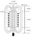
도 4는 본 발명의 배기 가스 처리 장치에 있어서의 자장에 의한 플라즈마의 제어 방법의 원리도이며, 반응관(및/또는 수냉 재킷)의 외주부에 배치된 코일에 전원 장치로부터 전류를 흘려보내는 방식을 나타내는 도면이다.
도 5는 본 발명의 배기 가스 처리 장치에 있어서의 자장에 의한 플라즈마의 제어 방법의 원리도이며, 도 5(a)는 반응관(및/또는 수냉 재킷)의 외주부에 배치한 코일에 전원 장치로부터 전류를 흘려보내는 방식을, 도 5(b)는 반응관(및/또는 수냉 재킷)의 외주부에 환상의 자석을 배치한 방식을, 도 5(c)는 반응관(및/또는 수냉 재킷)의 외주부에 막대 형상 또는 시트 형상의 자석을 배치한 방식을 나타내는 도면이다.
도 6은 본 발명의 배기 가스 처리 장치에 있어서의 자장에 의한 플라즈마의 제어 방법의 원리의 설명도이다.1 is a sectional view showing an embodiment of an exhaust gas processing apparatus using a plasma control method by a magnetic field in the exhaust gas processing apparatus of the present invention.
2 is a cross-sectional view showing a modification of the upper electrode.
3 is a cross-sectional view showing a modification of the lower electrode.
Fig. 4 is a principle diagram of a plasma control method using a magnetic field in the exhaust gas treating apparatus of the present invention, and shows a method of flowing a current from a power supply device to a coil disposed at the outer periphery of a reaction tube (and / or a water- Fig.
Fig. 5 is a principle diagram of a plasma control method using a magnetic field in the exhaust gas treating apparatus of the present invention. Fig. 5 (a) is a view showing a state in which a coil arranged on the outer periphery of a reaction tube FIG. 5B shows a system in which an annular magnet is arranged on the outer periphery of a reaction tube (and / or a water-cooling jacket), FIG. 5C shows a system in which a reaction tube And a rod-shaped or sheet-like magnet is disposed on the outer peripheral portion.
6 is an explanatory view of the principle of the plasma control method by the magnetic field in the exhaust gas processing apparatus of the present invention.
이하, 본 발명의 배기 가스 처리 장치에 있어서의 자장에 의한 플라즈마의 제어 방법 및 그것을 이용한 배기 가스 처리 장치의 실시형태를 도면에 의거하여 설명한다.DESCRIPTION OF THE PREFERRED EMBODIMENTS Hereinafter, a method of controlling a plasma by a magnetic field in an exhaust gas processing apparatus of the present invention and embodiments of an exhaust gas processing apparatus using the same will be described with reference to the drawings.
도 1에 배기 가스 처리 장치에 있어서의 자장에 의한 플라즈마의 제어 방법을 이용한 배기 가스 처리 장치의 일실시예를 나타낸다.Fig. 1 shows an embodiment of an exhaust gas processing apparatus using a plasma control method by a magnetic field in an exhaust gas processing apparatus.
이 배기 가스 처리 장치는 대기압하에서 전극간에 발생하는 플라즈마를 이용하여 예를 들면, CF4이나 SF6 등의 PFC 가스와 같은 배기 가스에 함유되는 유해 물질을 분해하여 처리하는 것이다.This exhaust gas treatment apparatus uses plasma generated between electrodes under atmospheric pressure to decompose and treat harmful substances contained in exhaust gases such as PFC gas such as CF4 and SF6 .
그리고, 이 배기 가스 처리 장치는 배기 가스(G)를 도입하는 플라즈마 방전부를 구성하는 반응관(1), 반응관(1)의 상부측에서 기중(氣中)에 배치된 상부 전극(2), 및 반응관(1)의 하부측에 배치된 하부 전극(3)을 구비하고, 전극(2,3) 사이에 전류의 경로를 형성하여 반응관(1) 내에 플라즈마(P)를 발생시키도록 하고 있다.The exhaust gas treatment apparatus includes a
이 경우에 있어서, 상부 전극(2)과 하부 전극(3) 사이에 전해질 용액(D)을 분무하는 분무 노즐(4)[본 실시예에 있어서는, 상부 전극(2)이 전해질 용액을 분무하는 분무 노즐(4)을 겸하도록 하고 있다.]을 배치할 수 있고, 상부 전극(2)과 하부 전극(3) 사이에 전해질 용액(D)을 분무함으로써 반응관(1) 내에 플라즈마를 안정되게 발생시킬 수 있도록 하고 있다.In this case, a spray nozzle 4 (in this embodiment, the upper electrode 2) for spraying the electrolyte solution D between the
반응관(1)은 세로 배치된 통체로 이루어지고, 산화알루미늄, 멀라이트(산화알류미늄과 이산화규소의 화합물), 석영, 지르코니아 등의 세라믹이나 염화비닐 수지 등의 합성 수지 등의 내열 재료로 구성되어 있다.The
반응관(1)은 공냉이어도 좋지만, 본 실시예에 있어서는 플라즈마 발생시에는 반응관(1)을 냉각하고, 플라즈마 정지시에는 물(H)을 반응관(1)의 내부에 넘쳐 흘려 세정하는 수냉 재킷(11)을 반응관(1)의 주위에 설치하고 있다.The
수냉 재킷(11)의 물(H)은 플라즈마 발생시에는 수냉 재킷(11)의 하부로부터 도입됨과 아울러 오버플로우 라인(12)으로부터 수조(6)로 흐르고, 또한 오버플로우 라인(62)으로부터 배출된다. 또, 물(H)로서는 새로운 물을 사용하여도 좋고, 배수를 순환시켜도 좋다.The water H of the water-
또한, 플라즈마 정지시에는 오버플로우 라인(12)의 밸브(13)를 폐쇄함으로써 물(H)을 반응관(1)의 내부에 넘쳐 흘려 세정한다.When the plasma is stopped, the
또, 배기 가스(G)는 반응관(1)의 상부 개구부로부터 도입되어 플라즈마(P)에 의해 유해 물질이 분해된 후 반응관(1)의 하부 개구부로부터 배출된다.The exhaust gas G is introduced from the upper opening of the
상부 전극(2)은 스테인리스, 하스텔로이, 텅스텐, SiC 등의 도전성 재료로 이루어지고, 반응관(1)의 상부 개구부에서 기중에 배치되어 있어 전원 장치(5)로부터 고압 전류가 인가된다. 그리고, 상부 전극(2)과 하부 전극(3)은 어느 쪽이 플러스라도 마이너스라도 좋다.The
이 경우에 있어서, 상부 전극(2)에는 이하의 구성의 것을 채용할 수 있다.In this case, the
(1) 상부 전극(2)이 전해질 용액을 분무하는 분무 노즐(4)을 겸하도록 한 것(본 실시예)(1) The
(1') 상부 전극(2)과 전해질 용액을 분무하는 분무 노즐(4)을 개별적으로 배치하도록 한 것[도 2(a)](Fig. 2 (a)) in which the
(2) 상부 전극(2)의 내부를 냉각을 위한 물(H)이 흐르도록 한 것[도 2(b)](2) The water H for cooling flows through the inside of the upper electrode 2 (Fig. 2 (b))
(3) 상부 전극(2)의 외부에 냉각 및 방식(防蝕)을 위한 물를 분무하는 분무 노즐(4A)을 배치하도록 한 것[도 2(c)](3) A
(4) 상부 전극(2)의 외부에 냉각 및 방식을 위한 실드 가스(불활성 가스)(Ga)를 흘려보내도록 한 것[도 2(d)](4) A shield gas (inert gas) Ga for cooling and a method is flowed to the outside of the upper electrode 2 (Fig. 2 (d)).
이에 따라, 고온에 노출되는 상부 전극(2)을 효율적으로 냉각함과 아울러 부식을 방지하고 상부 전극(2)이 소모되는 것을 방지할 수 있음과 아울러, 분무한 냉각 및 방식을 위한 물(H)은 스크러버로서 배기 가스(G)의 냉각이나 용해, 분체의 제거 등의 목적으로도 사용될 수 있다.Accordingly, it is possible to efficiently cool the
하부 전극(3)은 스테인리스, 하스텔로이, 텅스텐, SiC 등의 도전성 재료로 이루어지고, 반응관(1)의 하방에서 냉각 및 방식을 위한 물을 분무하는 스크러버 노즐을 겸하도록 형성되어 있다.The
하부 전극(3)에 의해 분무된 냉각 및 방식을 위한 물(H)은 수조(6)로부터 오버플로우 라인(62)을 통하여 배출된다. 또, 냉각 및 방식을 위한 물(H)로서는 새로운 물을 사용하여도 좋고, 배수를 순환시켜도 좋으며, 암모니아수 등의 약액을 사용하여도 좋다.The water H for cooling and the method sprayed by the
이 경우에 있어서, 하부 전극(3)에는 이하의 구성의 것을 채용할 수 있다.In this case, the
(5) 하부 전극(3)을 냉각 및 방식을 위한 물을 분무하는 노즐 형상으로 형성하도록 한 것(본 실시예)(5) The
(6) 하부 전극(3)을 냉각 및 방식을 위한 물(H)이 넘쳐 흐르는 형상으로 형성하도록 한 것[도 3(a)](6) The
(7) 하부 전극(3)의 내부를 냉각을 위한 물(H)이 흐르도록 한 것[도 3(b)](7) The water H for cooling flows in the lower electrode 3 (Fig. 3 (b))
(8) 하부 전극(3)의 외부에 냉각 및 방식을 위한 물을 분무하는 스크러버 노즐(64)을 배치하도록 한 것[도 3(c)](8) A
(9) 하부 전극(3)을 수조(6) 내에 수몰시키도록 한 것[도 3(d)](9) The
이에 따라, 고온에 노출되는 하부 전극(3)을 효율적으로 냉각함과 아울러 부식을 방지하고 하부 전극(3)이 소모되는 것을 방지할 수 있음과 아울러, 분무한 냉각 및 방식을 위한 물(H)은 스크러버로서 배기 가스(G)의 냉각이나 용해, 분체의 제거 등의 목적으로도 사용될 수 있다.As a result, it is possible to efficiently cool the
또, 본 실시예에 있어서 상부 전극(2)을 겸한 분무 노즐(4)은 반응관(1)의 상부 개구부에 배치되어 있어 상부 전극(2)과 하부 전극(3) 사이에 전해질 용액(D)을 분무한다.The atomizing
이 분무 노즐(4)에 의한 전해질 용액(D)의 분무는 플라즈마(P)의 점화 후에 정지하여도 좋고, 계속해서 분무하여도 좋다.The spraying of the electrolyte solution (D) by the spray nozzle (4) may be stopped after ignition of the plasma (P), or sprayed continuously.
전해질 용액(D)의 분무는 상부 전극(2)과 하부 전극(3) 사이에 전류의 경로를 형성할 수 있고, 이에 따라 플라즈마(P)의 발생을 용이하게 할 수 있다.Spraying of the electrolyte solution D can form a current path between the
또, 전해질 용액(D)으로서는 NaCl, CaCl2, MgCl2, NH4Cl, NaOH 등의 전해질을 용해한 용액을 사용할 수 있고, 특히 알칼리성의 전해질 용액을 사용함으로써 산성의 배기 가스를 중화시킬 수 있다.As the electrolyte solution (D), a solution prepared by dissolving an electrolyte such as NaCl, CaCl2 , MgCl2 , NH4 Cl or NaOH can be used. In particular, an acidic exhaust gas can be neutralized by using an alkaline electrolyte solution.
그리고, 본 실시예의 배기 가스 처리 장치에 있어서는, 도 1, 도 4 및 도 5(a)에 나타낸 바와 같이, 배기 가스(G)를 도입하는 플라즈마 방전부를 구성하는 반응관(1) 및(/또는) 수냉 재킷(11)의 외주부[본 명세서에 있어서, 포괄적으로 플라즈마 방전부의 외주부 또는 반응관(1)의 외주부라고 하는 경우가 있다.]에 자장 발생 수단(7)으로서 코일(71)을 배치하고, 이 코일(71)에 전원 장치(72)로부터 전류(특별히 한정되는 것은 아니지만, 본 실시예에 있어서는 직류 전류)를 흘려보냄으로써 플라즈마 방전부[플라즈마 방전부인 반응관(1) 내]에 자장[특별히 한정되는 것은 아니지만, 본 실시예에 있어서는 자력선이 상부 전극(2)으로부터 하부 전극(3)으로 향하는 자장]을 발생시키도록 한다.1, 4 and 5 (a), the
여기서, 자장 발생 수단(7)으로서의 코일(71)은 플라즈마 방전부를 구성하는 반응관(1) 및 수냉 재킷(11) 중 어느 한쪽의 외주부에 배치되도록 할 수 있다.Here, the
이에 따라, 플라즈마 방전부를 구성하는 반응관(1) 내에 발생된 플라즈마(P)의 상태를 제어함으로써, 더 구체적으로는 자장의 작용에 의해 플라즈마(P)를 형성하고 있는 하전 입자에 로렌츠 힘이 작용하고 또한 전자나 하전 입자의 산란을 방지하여 플라즈마(P)의 상태를 제어할 수 있고, 유효하게 사용되지 않고 소비되는 플라즈마(P)의 손실을 감소시켜 에너지의 소비량을 현저하게 증대시키거나 처리의 절대량을 저하시키지 않고 플라즈마(P)에 의해 행해지는 배기 가스의 처리 효율을 향상시킬 수 있다.Thus, by controlling the state of the plasma P generated in the
상기 작용을 도 6을 이용하여 설명한다.This operation will be described with reference to FIG.
자력선과 전자의 흐름 방향의 각도를 θ라고 하면, 전자 및 반응관(1) 내의 입자(중성 입자 이외)에 로렌츠 힘이 작용하고, 그 힘(F)은 하기의 식 (1)로 나타내어진다.The Lorentz force acts on the electrons and the particles (other than the neutral particles) in the
F = q(E+v×Bsinθ) … (1)F = q (E + v x Bsin?) ... (One)
여기서, E는 전계, q는 전하량, v는 입자의 속도이다.Where E is the electric field, q is the charge quantity, and v is the particle velocity.
θ=0°의 영역[반응관(1)의 중앙 영역]에서는 F=0이 되고 로렌츠 힘은 작용되지 않지만, 전자나 그 밖의 하전 입자가 도 6의 수직 방향[반응관(1) 내의 중심]으로부터 벗어나 산란되려고 하면 F가 작용되므로 산란이 억제된다.F = 0 in the region of? = 0 占 (the central region of the reaction tube 1) and no Lorentz force is applied, but electrons and other charged particles move in the vertical direction (center in the reaction tube 1) The scattering is suppressed because F is applied.
이에 따라, 이 영역에서는 반응관(1)으로 충돌되어 소실되는 플라즈마의 손실을 최소한으로 할 수 있다.Thus, in this region, the loss of the plasma that collides with the
한편, θ≠0°의 영역[반응관(1)의 단부 영역]에서는 로렌츠 힘이 v와 B 양쪽에 수직 힘 방향(백터로 말하면 v와 B의 외적)으로 작용되는 결과, 수직 방향의 운동 에너지는 이것을 유지한 채 하전 입자의 사이클로트론 운동(스핀 운동)으로 변화된다.On the other hand, in the region of the angle?? 0 (the end region of the reaction tube 1), the Lorentz force acts on both the v and B in the vertical force direction (the outer product of v and B in a vector) (Spin motion) of the charged particles while maintaining this.
이에 따라, 이 영역에서는 플라즈마 밀도가 높고 이 영역을 통과하는 배기 가스(G)는 자장이 없는 상태에 비해 열 전자나 여기된 하전 입자로의 충돌 확률이 높아지므로 처리 효율(분해 효율)이 향상되게 된다.Accordingly, in this region, the plasma density is high and the exhaust gas G passing through this region has a higher probability of collision with the thermal electrons and the excited charged particles as compared with the state where there is no magnetic field, so that the treatment efficiency (decomposition efficiency) do.
또, 자장 발생 수단(7)에는 본 실시예에 나타낸 배기 가스(G)를 도입하는 플라즈마 방전부를 구성하는 반응관(1)[및/또는 수냉 재킷(11)]의 외주부에 배치된 코일(71)에 전원 장치(72)로부터 전류를 흘려보내는 방식 이외에, 도 5(b) 및 도 5(c)에 나타낸 바와 같이, 반응관(1)[및/또는 수냉 재킷(11)]의 외주부에 환상의 자석(73)이나 막대 형상 또는 시트 형상의 자석(74)을 배치하는 방식을 채용할 수도 있다.The magnetic field generating means 7 is provided with a
[실시예][Example]
도 1에 나타낸 바와 같이, 배기 가스(G)를 도입하는 플라즈마 방전부를 구성하는 반응관(1) 및 수냉 재킷(11)의 외주부에 자장 발생 수단(7)으로서 코일(71)을 배치하고, 이 코일(71)에 전원 장치(72)로부터 전류(직류 전류)를 흘려보냄으로써 자장[자력선이 상부 전극(2)으로부터 하부 전극(3)으로 향하는 자장]을 발생시키도록 하여 배기 가스(G)로서 CF4를 분해하도록 하였다.As shown in Fig. 1, a
그 결과를 표 1에 나타낸다.
The results are shown in Table 1.
표 1에 나타낸 바와 같이, 코일(71)에 흘려보내는 전류값을 크게 하는 만큼 CF4의 분해율이 향상되는 것을 확인하였다.As shown in Table 1, it was confirmed that the decomposition rate of CF4 was improved by increasing the value of the current flowing through the
이상, 본 발명의 배기 가스 처리 장치에 있어서의 자장에 의한 플라즈마의 제어 방법 및 그것을 이용한 배기 가스 처리 장치에 대해서 그 실시예에 의거하여 설명하였지만, 본 발명은 상기 실시예에 기재한 구성에 한정되는 것은 아니고, 그 취지를 일탈하지 않는 범위에 있어서 적절하게 그 구성을 변경할 수 있는 것이다.The control method of the plasma by the magnetic field in the exhaust gas processing apparatus of the present invention and the exhaust gas processing apparatus using the same have been described above. However, the present invention is not limited to the configuration described in the above embodiment And it is possible to change the configuration appropriately within a range not deviating from the purpose.
본 발명의 배기 가스 처리 장치에 있어서의 자장에 의한 플라즈마의 제어 방법 및 그것을 이용한 배기 가스 처리 장치는 에너지의 소비량을 현저하게 증대시키거나 처리의 절대량을 저하시키지 않고 간이한 방법 및 구조로 플라즈마에 의해 행해지는 배기 가스의 처리 효율을 향상시킬 수 있는 특성을 갖고 있으므로 상기 실시예에 기재한 바와 같이 배기 가스 처리의 용도에 적합하게 사용될 수 있다.The method of controlling plasma by the magnetic field in the exhaust gas treating apparatus of the present invention and the exhaust gas treating apparatus using the same can be applied to plasma by a simple method and structure without remarkably increasing the consumption amount of energy or lowering the absolute amount of treatment It can be suitably used for the purpose of exhaust gas treatment as described in the above embodiment because it has properties that can improve the treatment efficiency of the exhaust gas to be performed.
1: 반응관(플라즈마 방전부) 11: 수냉 재킷
12: 오버플로우 라인 13: 밸브
2: 상부 전극 3: 하부 전극
4: 분무 노즐 5: 전원 장치
6: 수조 7: 자장 발생 수단
71: 코일 72: 전원 장치
73: 자석 74: 자석
G: 배기 가스 D: 전해질 용액
P: 플라즈마 H: 물1: reaction tube (plasma discharge part) 11: water-cooling jacket
12: overflow line 13: valve
2: upper electrode 3: lower electrode
4: Spray nozzle 5: Power supply unit
6: water tank 7: magnetic field generating means
71: coil 72: power supply
73: Magnet 74: Magnet
G: Exhaust gas D: Electrolyte solution
P: Plasma H: Water
Claims (6)
Translated fromKorean상기 반응관의 주위에 설치한 수냉 재킷 내에서, 또한, 반응관의 외주부를 따라 그 길이방향의 전장(全長)에 걸친 코일을 감아 배설(配設)하여, 그 코일에 전류를 흘려보냄으로써, 상기 반응관 내에 자장을 발생시키는 것에 의해, 상기 플라즈마의 상태를 제어하도록 한 것을 특징으로 하는 배기 가스 처리 장치에 있어서의 자장에 의한 플라즈마의 제어 방법.The exhaust gas introduced into the reaction tube as the plasma discharging portion consisting of the vertically arranged cylinder is disposed by arranging the upper electrode on the upper side of the reaction tube and the lower electrode on the lower side to form a current path between the two electrodes, A plasma control method for controlling a state of a plasma generated in a plasma discharge portion by generating a magnetic field in a plasma discharge portion of an exhaust gas processing apparatus that is decomposed by plasma generated in a reaction tube,
A coil wound around the entire length in the longitudinal direction along the outer periphery of the reaction tube is disposed in a water-cooled jacket provided around the reaction tube, and current is supplied to the coil, Wherein a state of the plasma is controlled by generating a magnetic field in the reaction tube. 2. A method for controlling a plasma by a magnetic field in an exhaust gas processing apparatus according to claim 1,
수냉 재킷의 외주부를 따라 그 길이방향의 전장에 걸쳐 코일을 감아 배설하여, 그 코일에 전류를 흘려보내는 것에 의해, 상기 반응관 내에 자장을 발생시킴으로써, 상기 플라즈마의 상태를 제어하도록 한 것을 특징으로 하는 배기 가스 처리 장치에 있어서의 자장에 의한 플라즈마의 제어 방법.The method according to claim 1,
The state of the plasma is controlled by winding a coil over the entire length in the longitudinal direction along the outer periphery of the water-cooling jacket and flowing a current through the coil to generate a magnetic field in the reaction tube. A method of controlling plasma by a magnetic field in an exhaust gas processing apparatus.
Applications Claiming Priority (2)
| Application Number | Priority Date | Filing Date | Title |
|---|---|---|---|
| JPJP-P-2009-090066 | 2009-04-02 | ||
| JP2009090066AJP4955027B2 (en) | 2009-04-02 | 2009-04-02 | Control method of plasma by magnetic field in exhaust gas treatment device |
Publications (2)
| Publication Number | Publication Date |
|---|---|
| KR20100110267A KR20100110267A (en) | 2010-10-12 |
| KR101659389B1true KR101659389B1 (en) | 2016-09-23 |
Family
ID=42314811
Family Applications (1)
| Application Number | Title | Priority Date | Filing Date |
|---|---|---|---|
| KR1020100027253AActiveKR101659389B1 (en) | 2009-04-02 | 2010-03-26 | Control method of plasma for exhaust gas treating apparatus using magnetic field and exhaust gas treating apparatus using the same |
Country Status (6)
| Country | Link |
|---|---|
| US (1) | US9675930B2 (en) |
| EP (1) | EP2236193B1 (en) |
| JP (1) | JP4955027B2 (en) |
| KR (1) | KR101659389B1 (en) |
| CN (1) | CN101856581B (en) |
| TW (1) | TWI476039B (en) |
Families Citing this family (24)
| Publication number | Priority date | Publication date | Assignee | Title |
|---|---|---|---|---|
| KR101230513B1 (en)* | 2010-12-27 | 2013-02-06 | (주)엘오티베큠 | Treatment apparatus for discharging fluid |
| JP5540035B2 (en)* | 2012-03-22 | 2014-07-02 | カンケンテクノ株式会社 | Gas processing equipment |
| WO2013161423A1 (en)* | 2012-04-26 | 2013-10-31 | 株式会社日立国際電気 | Exhaust gas processing device, exhaust gas processing system, method for controlling exhaust gas processing system, control program, and cylindrical tube |
| WO2015026057A1 (en)* | 2013-08-22 | 2015-02-26 | (주)클린팩터스 | Plasma reactor |
| KR101448449B1 (en)* | 2014-01-13 | 2014-10-13 | 주식회사 테라텍 | Using a high-density plasma source perfluorocarbons redemption and harmful gas cracker |
| US9240308B2 (en)* | 2014-03-06 | 2016-01-19 | Applied Materials, Inc. | Hall effect enhanced capacitively coupled plasma source, an abatement system, and vacuum processing system |
| KR101557880B1 (en)* | 2014-07-07 | 2015-10-13 | (주)클린팩터스 | Low pressure plasma reactor for exhaust gas treatment |
| CN104548832A (en)* | 2014-11-05 | 2015-04-29 | 华玉叶 | Combined method for purifying dusty flue gas |
| CN106268169A (en)* | 2015-06-01 | 2017-01-04 | 杭州中兵环保股份有限公司 | The apparatus and method of the collaborative light electrolysis cleaning organic waste gas of plasma cracking oxidation |
| PL417687A1 (en)* | 2016-06-22 | 2017-05-22 | Bicarbo Spółka Z Ograniczoną Odpowiedzialnością | Method for separation of gas mixture and the centrifuge for separation of gas mixture |
| US10307726B1 (en)* | 2016-11-15 | 2019-06-04 | Rodolfo Palombo | Magnetic chemical reactor |
| KR102686242B1 (en)* | 2017-01-23 | 2024-07-17 | 에드워드 코리아 주식회사 | Nitrogen oxide reduction apparatus and gas treating apparatus |
| KR102646623B1 (en)* | 2017-01-23 | 2024-03-11 | 에드워드 코리아 주식회사 | Plasma generating apparatus and gas treating apparatus |
| CN108325351B (en)* | 2018-02-24 | 2020-11-13 | 泰州远创新材料科技有限公司 | Electromagnetic induction coupling double-medium low-temperature plasma gas purification device |
| CN108339379B (en)* | 2018-02-24 | 2020-11-13 | 泰州远创新材料科技有限公司 | Electromagnetic induction coupling-based double-medium low-temperature plasma waste gas treatment device |
| JP7109311B2 (en)* | 2018-08-27 | 2022-07-29 | 国立大学法人埼玉大学 | Combustion furnace for harmful exhaust gas treatment equipment using magnetic field generation |
| JP2020034180A (en)* | 2018-08-27 | 2020-03-05 | 国立大学法人埼玉大学 | Combustion furnace of harmful exhaust gas processing device using alternating electric fields |
| CN109157952B (en)* | 2018-10-22 | 2023-10-27 | 广西博世科环保科技股份有限公司 | Integrated catering oil smoke purifying device |
| CN109482046B (en)* | 2018-12-07 | 2020-09-11 | 中国矿业大学(北京) | A explosion-proof anti-poisoning device for phenol-cyanogen wastewater sludge well overhauls |
| WO2020157649A1 (en)* | 2019-01-29 | 2020-08-06 | Persapien Innovations Private Limited | A device and method for using pollutants and source of pollution as pollution abatement agents |
| CN110314620B (en)* | 2019-07-15 | 2022-01-14 | 惠州市臻鼎环保科技有限公司 | High-efficient gas-liquid mixture device that sprays |
| CN110793046A (en)* | 2019-10-09 | 2020-02-14 | 浙江理工大学 | Magnetic auxiliary combustion and heat recovery device for heat-setting waste gas volatile organic compounds |
| KR102240709B1 (en)* | 2021-01-13 | 2021-04-15 | (주)이엠씨 | Plasma effector for Wet Smoke and Post-Processing System |
| CN116589041B (en)* | 2023-03-31 | 2025-09-05 | 华中科技大学 | An activated water preparation device and method based on water curtain plasma |
Citations (1)
| Publication number | Priority date | Publication date | Assignee | Title |
|---|---|---|---|---|
| JP2002294433A (en) | 2001-03-29 | 2002-10-09 | Nissin Electric Co Ltd | Vacuum arc deposition apparatus |
Family Cites Families (63)
| Publication number | Priority date | Publication date | Assignee | Title |
|---|---|---|---|---|
| US2941012A (en)* | 1958-04-23 | 1960-06-14 | Du Pont | Preparation of tetrafluoroethylene |
| US3087840A (en)* | 1958-06-16 | 1963-04-30 | Macrosonic Process Corp | Methods and means for producing physical, chemical and physicochemical effects by large-amplitude sound waves |
| US2952706A (en)* | 1958-09-15 | 1960-09-13 | Du Pont | Preparation of thiocarbonyl fluoride |
| US3091920A (en)* | 1959-11-16 | 1963-06-04 | Matvay Leo | Plasma flame hyperthermal exothermic furnace with catalyst and combination thereof with an internal combustion engine |
| US3081245A (en)* | 1960-03-17 | 1963-03-12 | Du Pont | Method for the preparation of tetrafluoroethylene |
| US3209189A (en)* | 1961-03-29 | 1965-09-28 | Avco Corp | Plasma generator |
| DE1255833B (en)* | 1963-08-10 | 1967-12-07 | Siemens Ag | Method and device for heating gases in a plasma torch |
| DE1433898A1 (en)* | 1964-04-30 | 1970-02-05 | Euratom | Device for melting metals and compounds with a high melting point |
| US3388291A (en)* | 1964-08-31 | 1968-06-11 | Electro Optical Systems Inc | Annular magnetic hall current accelerator |
| DE1301303B (en)* | 1964-10-01 | 1969-08-21 | Ppg Industries Inc | Process for the production of finely divided metal oxide pigments |
| US3316082A (en)* | 1964-12-08 | 1967-04-25 | Inland Steel Co | Oxygen steelmaking |
| US3343022A (en)* | 1965-03-16 | 1967-09-19 | Lockheed Aircraft Corp | Transpiration cooled induction plasma generator |
| DE1225311B (en)* | 1965-04-12 | 1966-09-22 | Siemens Ag | Plasma torch |
| US3376211A (en)* | 1965-04-19 | 1968-04-02 | Phillips Petroleum Co | Method and apparatus for performing chemical reactions by means of an electric arc |
| US3400070A (en)* | 1965-06-14 | 1968-09-03 | Hercules Inc | High efficiency plasma processing head including a diffuser having an expanding diameter |
| DE1271852C2 (en)* | 1966-11-05 | 1975-07-31 | Siemens Aktiengesellschaft, 1000 Berlin und 8000 München | PLASMA BURNER |
| US3541379A (en)* | 1967-09-11 | 1970-11-17 | Ppg Industries Inc | Method for initiating gaseous plasmas |
| CA871894A (en)* | 1968-08-02 | 1971-05-25 | Canadian Titanium Pigments Limited | Plasma arc heating apparatus |
| US3695840A (en)* | 1970-05-04 | 1972-10-03 | Ppg Industries Inc | Method of preparing metal oxides with arc gas heaters |
| BE791550A (en)* | 1971-11-20 | 1973-03-16 | Max Planck Gesellschaft | METHOD AND DEVICE FOR TREATING A MATERIAL BY MEANS OF PLASMA FROM AN ELECTRIC ARC |
| JPS5532317A (en)* | 1978-08-28 | 1980-03-07 | Asahi Chemical Ind | High frequency magnetic field coupling arc plasma reactor |
| CA1225441A (en)* | 1984-01-23 | 1987-08-11 | Edward S. Fox | Plasma pyrolysis waste destruction |
| JPS6331523A (en)* | 1986-07-25 | 1988-02-10 | Oyo Kagaku Kenkyusho | Apparatus for treating waste gas |
| DE3632340C2 (en)* | 1986-09-24 | 1998-01-15 | Leybold Ag | Inductively excited ion source |
| JP2598435B2 (en)* | 1987-12-02 | 1997-04-09 | 三井東圧化学株式会社 | Exhaust gas discharge treatment equipment |
| US4945721A (en)* | 1988-04-14 | 1990-08-07 | Environmental Research International, Inc. | Electromagnetic converter for reduction of exhaust emissions |
| JPH01297126A (en)* | 1988-05-26 | 1989-11-30 | Mitsui Toatsu Chem Inc | Exhaust gas treatment equipment |
| US5028452A (en)* | 1989-09-15 | 1991-07-02 | Creative Systems Engineering, Inc. | Closed loop system and process for conversion of gaseous or vaporizable organic and/or organo-metallic compounds to inert solid matrix resistant to solvent extraction |
| US5188704A (en)* | 1989-10-20 | 1993-02-23 | International Business Machines Corporation | Selective silicon nitride plasma etching |
| JPH084708B2 (en)* | 1989-11-08 | 1996-01-24 | 三井東圧化学株式会社 | Exhaust gas treatment device |
| JPH04110015A (en)* | 1990-08-30 | 1992-04-10 | Mitsui Toatsu Chem Inc | Exhaust gas treatment equipment |
| US5714306A (en)* | 1990-09-26 | 1998-02-03 | Canon Kabushiki Kaisha | Processing method and apparatus |
| US5288969A (en)* | 1991-08-16 | 1994-02-22 | Regents Of The University Of California | Electrodeless plasma torch apparatus and methods for the dissociation of hazardous waste |
| JP3542378B2 (en)* | 1994-05-17 | 2004-07-14 | 中部電力株式会社 | Manufacturing method of oxide superconducting wire |
| US5611947A (en)* | 1994-09-07 | 1997-03-18 | Alliant Techsystems, Inc. | Induction steam plasma torch for generating a steam plasma for treating a feed slurry |
| US5607542A (en)* | 1994-11-01 | 1997-03-04 | Applied Materials Inc. | Inductively enhanced reactive ion etching |
| EP0801809A2 (en)* | 1995-06-19 | 1997-10-22 | The University Of Tennessee Research Corporation | Discharge methods and electrodes for generating plasmas at one atmosphere of pressure, and materials treated therewith |
| JPH10216460A (en)* | 1997-01-31 | 1998-08-18 | Hitachi Ltd | Electron beam gas processing equipment |
| RU2127400C1 (en)* | 1998-03-18 | 1999-03-10 | Акционерное общество закрытого типа "Карбид" | Plasma cleaning device for gases produced in fuel combustion |
| JP2000133494A (en)* | 1998-10-23 | 2000-05-12 | Mitsubishi Heavy Ind Ltd | Microwave plasma generation device and method |
| SE516336C2 (en)* | 1999-04-28 | 2001-12-17 | Hana Barankova | Apparatus for plasma treatment of surfaces |
| DE19927540A1 (en)* | 1999-06-16 | 2000-12-21 | Ct Therm Elek Sche Anlagen Gmb | Emission control system |
| US6689252B1 (en)* | 1999-07-28 | 2004-02-10 | Applied Materials, Inc. | Abatement of hazardous gases in effluent |
| US6468489B1 (en)* | 1999-08-10 | 2002-10-22 | Electric Power Research Institute, Inc. | Apparatus and method for decreasing contaminants present in a gas stream |
| KR20010062209A (en)* | 1999-12-10 | 2001-07-07 | 히가시 데쓰로 | Processing apparatus with a chamber having therein a high-etching resistant sprayed film |
| JP2001254929A (en)* | 2000-01-07 | 2001-09-21 | Yyl:Kk | Method and device for treating dioxin |
| US6617538B1 (en)* | 2000-03-31 | 2003-09-09 | Imad Mahawili | Rotating arc plasma jet and method of use for chemical synthesis and chemical by-products abatements |
| JP2003113707A (en)* | 2001-10-02 | 2003-04-18 | Michio Uemura | Removal method of internal combustion engine exhaust particulate using microwave |
| US6936231B2 (en)* | 2001-12-06 | 2005-08-30 | Powerspan Corp. | NOx, Hg, and SO2 removal using ammonia |
| US20040245085A1 (en)* | 2002-03-13 | 2004-12-09 | Gopalakrishnan Srinivasan | Process and synthesizer for molecular engineering and synthesis of materials |
| JP2004154654A (en)* | 2002-11-05 | 2004-06-03 | Masuhiro Kokoma | Plasma reactor and method |
| JP3933035B2 (en)* | 2002-11-06 | 2007-06-20 | 富士ゼロックス株式会社 | Carbon nanotube manufacturing apparatus and manufacturing method |
| JP4107959B2 (en)* | 2002-12-27 | 2008-06-25 | 株式会社アドテック プラズマ テクノロジー | Discharge starting method, processing object processing method using the starting method, and processing object processing apparatus using the starting method |
| US6851413B1 (en)* | 2003-01-10 | 2005-02-08 | Ronnell Company, Inc. | Method and apparatus to increase combustion efficiency and to reduce exhaust gas pollutants from combustion of a fuel |
| KR20040069420A (en)* | 2003-01-29 | 2004-08-06 | 주성엔지니어링(주) | Method of Cleaning for Thin Film Deposition Chamber |
| US7429714B2 (en)* | 2003-06-20 | 2008-09-30 | Ronal Systems Corporation | Modular ICP torch assembly |
| JP2005138055A (en)* | 2003-11-07 | 2005-06-02 | Nissan Motor Co Ltd | Exhaust gas purification device, exhaust gas purification method, and exhaust gas purification system |
| JP2005166458A (en)* | 2003-12-03 | 2005-06-23 | Fujisawa Pharmaceut Co Ltd | Plasma surface treatment method and its device |
| WO2007059012A2 (en)* | 2005-11-10 | 2007-05-24 | Staton Vernon E | Enhanced plasma filter |
| US7452513B2 (en)* | 2006-09-02 | 2008-11-18 | Igor Matveev | Triple helical flow vortex reactor |
| JP4588726B2 (en)* | 2007-02-08 | 2010-12-01 | クリーン・テクノロジー株式会社 | Exhaust gas treatment equipment |
| JP2009010043A (en)* | 2007-06-26 | 2009-01-15 | Tokyo Electron Ltd | Substrate processing method, substrate processor, and recording medium |
| CN101239269A (en)* | 2007-11-21 | 2008-08-13 | 中山大学 | Rotary discharge low temperature plasma organic waste gas purification device |
- 2009
- 2009-04-02JPJP2009090066Apatent/JP4955027B2/enactiveActive
- 2010
- 2010-03-25EPEP10157820.1Apatent/EP2236193B1/enactiveActive
- 2010-03-25TWTW099108901Apatent/TWI476039B/enactive
- 2010-03-26KRKR1020100027253Apatent/KR101659389B1/enactiveActive
- 2010-04-01USUS12/752,537patent/US9675930B2/enactiveActive
- 2010-04-02CNCN201010154437.2Apatent/CN101856581B/enactiveActive
Patent Citations (1)
| Publication number | Priority date | Publication date | Assignee | Title |
|---|---|---|---|---|
| JP2002294433A (en) | 2001-03-29 | 2002-10-09 | Nissin Electric Co Ltd | Vacuum arc deposition apparatus |
Also Published As
| Publication number | Publication date |
|---|---|
| US20100252411A1 (en) | 2010-10-07 |
| KR20100110267A (en) | 2010-10-12 |
| EP2236193A1 (en) | 2010-10-06 |
| JP4955027B2 (en) | 2012-06-20 |
| TWI476039B (en) | 2015-03-11 |
| TW201043329A (en) | 2010-12-16 |
| EP2236193B1 (en) | 2017-03-08 |
| US9675930B2 (en) | 2017-06-13 |
| JP2010240534A (en) | 2010-10-28 |
| CN101856581A (en) | 2010-10-13 |
| CN101856581B (en) | 2015-01-07 |
Similar Documents
| Publication | Publication Date | Title |
|---|---|---|
| KR101659389B1 (en) | Control method of plasma for exhaust gas treating apparatus using magnetic field and exhaust gas treating apparatus using the same | |
| KR101464997B1 (en) | Apparatus for treating exhaust gas | |
| KR102646623B1 (en) | Plasma generating apparatus and gas treating apparatus | |
| JP5891341B2 (en) | Plasma generating apparatus and method | |
| CN106062925B (en) | Hall effect enhanced capacitively coupled plasma source, abatement system and vacuum processing system | |
| CN113330824B (en) | Thermal plasma treatment equipment | |
| KR102686242B1 (en) | Nitrogen oxide reduction apparatus and gas treating apparatus | |
| KR20180066576A (en) | Arc plasma waste gas treatment apparatus | |
| KR101961947B1 (en) | Exhaust gas treatment device | |
| KR20120021651A (en) | Apparatus and method for pfcs gas decomposition | |
| KR102520818B1 (en) | Scrubber having protrude electrode, scrubber system including the same, and scrubber operating method | |
| KR100937697B1 (en) | Waste gas treatment system | |
| KR101177283B1 (en) | Plasma torch for treating waste air of chemical vapor deposition processing | |
| KR101177276B1 (en) | Plasma torch for treating waste air of etching processing | |
| KR102589742B1 (en) | Plasma generator for gas abatement | |
| KR101840648B1 (en) | Gas dissociation system | |
| TWM571103U (en) | Water molecule supply device for electric torch |
Legal Events
| Date | Code | Title | Description |
|---|---|---|---|
| PA0109 | Patent application | Patent event code:PA01091R01D Comment text:Patent Application Patent event date:20100326 | |
| PG1501 | Laying open of application | ||
| A201 | Request for examination | ||
| PA0201 | Request for examination | Patent event code:PA02012R01D Patent event date:20150205 Comment text:Request for Examination of Application Patent event code:PA02011R01I Patent event date:20100326 Comment text:Patent Application | |
| E902 | Notification of reason for refusal | ||
| PE0902 | Notice of grounds for rejection | Comment text:Notification of reason for refusal Patent event date:20160115 Patent event code:PE09021S01D | |
| E701 | Decision to grant or registration of patent right | ||
| PE0701 | Decision of registration | Patent event code:PE07011S01D Comment text:Decision to Grant Registration Patent event date:20160728 | |
| GRNT | Written decision to grant | ||
| PR0701 | Registration of establishment | Comment text:Registration of Establishment Patent event date:20160919 Patent event code:PR07011E01D | |
| PR1002 | Payment of registration fee | Payment date:20160920 End annual number:3 Start annual number:1 | |
| PG1601 | Publication of registration | ||
| FPAY | Annual fee payment | Payment date:20190607 Year of fee payment:4 | |
| PR1001 | Payment of annual fee | Payment date:20190607 Start annual number:4 End annual number:4 | |
| PR1001 | Payment of annual fee | Payment date:20200520 Start annual number:5 End annual number:5 | |
| PR1001 | Payment of annual fee | Payment date:20210514 Start annual number:6 End annual number:6 | |
| PR1001 | Payment of annual fee | Payment date:20220512 Start annual number:7 End annual number:7 | |
| PR1001 | Payment of annual fee | Payment date:20230517 Start annual number:8 End annual number:8 | |
| PR1001 | Payment of annual fee | Payment date:20240523 Start annual number:9 End annual number:9 | |
| PR1001 | Payment of annual fee | Payment date:20250611 Start annual number:10 End annual number:10 |