KR101659251B1 - Discernment system for driving lane data or road information and discernment method using the same - Google Patents
Discernment system for driving lane data or road information and discernment method using the sameDownload PDFInfo
- Publication number
- KR101659251B1 KR101659251B1KR1020160047358AKR20160047358AKR101659251B1KR 101659251 B1KR101659251 B1KR 101659251B1KR 1020160047358 AKR1020160047358 AKR 1020160047358AKR 20160047358 AKR20160047358 AKR 20160047358AKR 101659251 B1KR101659251 B1KR 101659251B1
- Authority
- KR
- South Korea
- Prior art keywords
- mark
- information
- road
- identification
- vehicle
- Prior art date
- Legal status (The legal status is an assumption and is not a legal conclusion. Google has not performed a legal analysis and makes no representation as to the accuracy of the status listed.)
- Active
Links
Images


Classifications
- G—PHYSICS
- G06—COMPUTING OR CALCULATING; COUNTING
- G06V—IMAGE OR VIDEO RECOGNITION OR UNDERSTANDING
- G06V20/00—Scenes; Scene-specific elements
- G06V20/50—Context or environment of the image
- G06V20/56—Context or environment of the image exterior to a vehicle by using sensors mounted on the vehicle
- G06V20/588—Recognition of the road, e.g. of lane markings; Recognition of the vehicle driving pattern in relation to the road
- G06K9/00798—
- B—PERFORMING OPERATIONS; TRANSPORTING
- B60—VEHICLES IN GENERAL
- B60W—CONJOINT CONTROL OF VEHICLE SUB-UNITS OF DIFFERENT TYPE OR DIFFERENT FUNCTION; CONTROL SYSTEMS SPECIALLY ADAPTED FOR HYBRID VEHICLES; ROAD VEHICLE DRIVE CONTROL SYSTEMS FOR PURPOSES NOT RELATED TO THE CONTROL OF A PARTICULAR SUB-UNIT
- B60W40/00—Estimation or calculation of non-directly measurable driving parameters for road vehicle drive control systems not related to the control of a particular sub unit, e.g. by using mathematical models
- B60W40/02—Estimation or calculation of non-directly measurable driving parameters for road vehicle drive control systems not related to the control of a particular sub unit, e.g. by using mathematical models related to ambient conditions
- B—PERFORMING OPERATIONS; TRANSPORTING
- B60—VEHICLES IN GENERAL
- B60W—CONJOINT CONTROL OF VEHICLE SUB-UNITS OF DIFFERENT TYPE OR DIFFERENT FUNCTION; CONTROL SYSTEMS SPECIALLY ADAPTED FOR HYBRID VEHICLES; ROAD VEHICLE DRIVE CONTROL SYSTEMS FOR PURPOSES NOT RELATED TO THE CONTROL OF A PARTICULAR SUB-UNIT
- B60W40/00—Estimation or calculation of non-directly measurable driving parameters for road vehicle drive control systems not related to the control of a particular sub unit, e.g. by using mathematical models
- B60W40/10—Estimation or calculation of non-directly measurable driving parameters for road vehicle drive control systems not related to the control of a particular sub unit, e.g. by using mathematical models related to vehicle motion
- G—PHYSICS
- G06—COMPUTING OR CALCULATING; COUNTING
- G06F—ELECTRIC DIGITAL DATA PROCESSING
- G06F18/00—Pattern recognition
- G06F18/20—Analysing
- G06F18/22—Matching criteria, e.g. proximity measures
- G06K9/00825—
- G06K9/6201—
- G—PHYSICS
- G06—COMPUTING OR CALCULATING; COUNTING
- G06V—IMAGE OR VIDEO RECOGNITION OR UNDERSTANDING
- G06V20/00—Scenes; Scene-specific elements
- G06V20/50—Context or environment of the image
- G06V20/56—Context or environment of the image exterior to a vehicle by using sensors mounted on the vehicle
- G06V20/58—Recognition of moving objects or obstacles, e.g. vehicles or pedestrians; Recognition of traffic objects, e.g. traffic signs, traffic lights or roads
- G06V20/584—Recognition of moving objects or obstacles, e.g. vehicles or pedestrians; Recognition of traffic objects, e.g. traffic signs, traffic lights or roads of vehicle lights or traffic lights
Landscapes
- Engineering & Computer Science (AREA)
- Physics & Mathematics (AREA)
- Mechanical Engineering (AREA)
- Transportation (AREA)
- Mathematical Physics (AREA)
- Automation & Control Theory (AREA)
- Theoretical Computer Science (AREA)
- General Physics & Mathematics (AREA)
- Data Mining & Analysis (AREA)
- Multimedia (AREA)
- Bioinformatics & Cheminformatics (AREA)
- General Engineering & Computer Science (AREA)
- Evolutionary Computation (AREA)
- Evolutionary Biology (AREA)
- Computer Vision & Pattern Recognition (AREA)
- Bioinformatics & Computational Biology (AREA)
- Artificial Intelligence (AREA)
- Life Sciences & Earth Sciences (AREA)
- Traffic Control Systems (AREA)
Abstract
Description
Translated fromKorean본 발명은 주행 차로 정보 또는 도로 정보 식별 시스템 및 이를 이용한 식별 방법에 관한 것이다. 보다 상세하게는 도로 차선, 차로, 표지판, 가드레일 또는 중앙 분리대 등에 카메라가 인식할 수 있는 특정 마크를 형성하여, 용이하게 상기 차량의 주행 차로 정보 및 도로 정보를 식별하는 것이 가능한 주행 차로 정보 또는 도로 정보 식별 시스템 및 이를 이용한 식별 방법에 관한 것이다.The present invention relates to a driving lane information or road information identification system and an identification method using the same. More particularly, the present invention relates to driving lane information or road information that can identify a driving lane information and road information of the vehicle easily by forming a specific mark recognizable by a camera on a road lane, a lane, a sign, a guard rail, An information identification system and an identification method using the same.
현대 사회에서는 물적, 인적인 이동이 점증하면서 도로 및 차량과 같은 교통 기반시설과 교통수단이 계속 증가하고 있다. 이러한 교통 시설과 수단은 한편으로는 편익을 제공하지만 반면 교통사고나 공해와 같은 문제를 일으키기도 하며, 교통량의 폭주와 집중, 자연재해나 공사 등의 요인에 의한 교통의 지체와 정체도 현실적인 문제가 되고 있다.In modern society, physical and human movements are increasing, and traffic infrastructure and transportation such as roads and vehicles continue to increase. Such traffic facilities and means provide benefits on the one hand, but they also cause problems such as traffic accidents and pollution. Traffic congestion and congestion caused by traffic congestion and concentration, natural disasters and construction are also real problems. .
최근에는 차량에 교통사고 저감을 위한 안전성과 도로에서의 교통 효율성, 연료절감을 통한 환경 친화성 및 편의성 등을 제공하기 위해 주행 차로 정보 또는 도로 정보의 식별 시스템이 적용되고 있다.In recent years, driving lane information or road information identification system has been applied to provide safety for traffic accident reduction in vehicles, traffic efficiency on roads, environment friendliness and convenience through fuel saving.
하지만, 종래의 주행 차로 정보 또는 도로 정보의 식별 시스템은 GPS 등과 같은 위성 항법을 이용하며, 위치 정보와 실제 차선정보의 맵 매칭(map matching)을 통하여 무인 자율주행 자동차의 현재 위치정보를 보정하여, 차량의 주행 차로에 대한 정보와 진입 램프, 진출 램프, 분기점 또는 휴게소 등에 관한 도로 정보를 인지할 수 있다.However, the conventional navigation system for identifying information or road information uses satellite navigation such as GPS and corrects the current position information of the unmanned autonomous vehicle through map matching between the position information and the actual lane information, Information on the driving lane of the vehicle, and road information regarding the entry ramp, the entry ramp, the turning point, the rest area, and the like can be recognized.
이러한 종래의 시스템은 GPS 등의 위성 항법과 같은 고가의 센서를 이용하여야 하며, 각 장비 마다 정밀도가 차이가 발생하는 문제점이 있다.Such a conventional system should use an expensive sensor such as a GPS satellite navigation system, and there is a problem that a difference in precision is generated for each equipment.
본 발명은 도로 차선, 차로, 표지판, 가드레일 또는 중앙 분리대 등에 카메라가 인식할 수 있는 특정 마크를 형성하여, 용이하게 상기 차량의 주행 차로 정보 및 도로 정보를 식별하는 것이 가능한 주행 차로 정보 또는 도로 정보 식별 시스템 및 이를 이용한 식별 방법에 관한 것이다.The present invention forms a specific mark that can be recognized by a camera on a road lane, a lane, a sign, a guardrail or a median separator, so as to easily identify driving lane information or road information of the vehicle, And an identification method using the same.
또한, 본 발명은 고가의 센서를 대체할 수 있어, 경제적인 주행 차로 정보 또는 도로 정보 식별 시스템 및 이를 이용한 식별 방법에 관한 것이다.The present invention also relates to an economical running lane information or road information identification system and an identification method using the same, which can replace expensive sensors.
한편, 본 발명에서 이루고자 하는 기술적 과제들은 이상에서 언급한 기술적 과제들로 제한되지 않으며, 언급하지 않은 또 다른 기술적 과제들은 아래의 기재로부터 본 발명이 속하는 기술분야에서 통상의 지식을 가진 자에게 명확하게 이해될 수 있을 것이다.It is to be understood that both the foregoing general description and the following detailed description of the present invention are exemplary and explanatory and are not intended to limit the invention to the precise form disclosed. It can be understood.
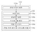
본 발명의 일 실시예에 따른 주행 차로 정보 또는 도로 정보 식별 시스템은 차량 전방의 영상 데이터를 획득하는 촬영부, 영상 데이터를 통해 차량의 주행 차로 정보 및 도로 정보를 식별하는 식별부 및 식별된 차량의 주행 차로 정보 또는 도로 정보에 따라 차량의 주행 속도 및 주행 방향을 제어하는 제어부를 포함하고, 도로상에는 주행 차로 식별 마크 및 도로 정보 식별 마크 중 적어도 하나가 형성되고, 식별부는 주행 차로 식별 마크와 도로 정보 식별 마크 중 적어도 하나를 인식하여, 차량의 주행 차로 정보 또는 도로 정보를 식별할 수 있다.The driving lane information or road information identification system according to an embodiment of the present invention includes a photographing unit for acquiring image data in front of the vehicle, an identification unit for identifying driving lane information and road information of the vehicle through the image data, And a control unit for controlling a running speed and a running direction of the vehicle in accordance with the driving lane information or the road information, wherein at least one of an identification mark and a road information identification mark is formed as a driving lane on the road, At least one of the identification marks can be recognized and the driving lane information or the road information of the vehicle can be identified.
또한, 주행 차로 식별 마크는 도로 중 중앙선 또는 중앙 분리대에 형성된 중앙선 마크, 도로 중 1차로에 형성된 제 1 마크 및 도로 중 2차로에 형성된 제 2 마크를 포함하고, 식별부는 영상 데이터에서 제 1 마크를 인식하면, 차량이 1차로로 주행 중인 것으로 식별하고, 영상 데이터에서 제 2 마크를 인식하면, 차량이 2차로로 주행 중인 것으로 식별할 수 있다.In addition, the driving vehicle identification mark includes a center mark formed on the center line or the center separator of the road, a first mark formed on the first lane of the road, and a second mark formed on the second lane of the road, If it is recognized, it can be identified that the vehicle is traveling in the primary position, and the vehicle is recognized as traveling in the secondary position when the second mark is recognized in the image data.
또한, 중앙선 마크, 제 1 마크 및 제 2 마크는 서로 상이할 수 있다.Further, the center mark, the first mark, and the second mark may be different from each other.
도로에서 차로의 번호가 증가할수록, 주행 차로 식별 마크에 포함된 도형의 개수가 증가할 수 있다.As the number of roads from the road increases, the number of figures included in the identification mark as a driving vehicle may increase.
또한, 제 1 마크는 1차로 중앙에 형성되고, 제 2 마크는 2차로 중앙에 형성될 수 있다.Also, the first mark may be formed at the center in the first place, and the second mark may be formed at the center in the second place.
또한, 제 1 마크는 1차로 일측 차선에 형성되고, 제 2 마크는 2차로 일측 차선에 형성될 수 있다.Further, the first mark may be formed primarily in one lane, and the second mark may be formed in the second lane.
또한, 도로 상부에 배치되며, 제 1 마크 및 제 2 마크가 형성된 표지판을 더 포함하고, 제 1 마크는 1차로 상부에 형성되고, 제 2 마크는 2차로 상부에 형성될 수 있다.The display device may further include a sign disposed above the road and having a first mark and a second mark formed thereon, wherein the first mark is formed on the upper side and the second mark is formed on the upper side.
또한, 도로 정보는 등록 지점의 위치 정보 및 거리 정보이며, 등록 지점은 교차로, 고가도로, 지하도로, 나들목, 분기점, 요금소 또는 휴게소이고, 도로 정보 식별 마크는 등록 지점 마다 상이한 도형으로 형성될 수 있다.In addition, the road information is location information and distance information of the registration point, and the registration point is an intersection, an overpass, an underpass, a junction, a branch point, a tollgate or rest area, and the road information identification mark may be formed in a different figure for each registration point.
또한, 도로 정보 식별 마크는 등록 지점 중 적어도 하나까지의 거리를 안내하는 거리 안내 마크를 포함하고, 식별부는 영상 데이터에서 거리 안내 마크를 인식하여, 차량의 주행 전방에 위치한 등록 지점까지의 거리를 식별할 수 있다.Further, the road information identification mark includes a distance guide mark for guiding the distance to at least one of the registration points, and the identification unit recognizes the distance guide mark in the image data, and identifies the distance to the registration point located in front of the vehicle can do.
또한, 거리 안내 마크는 등록 지점까지의 일정거리별로 상이하게 형성되며, 등록 지점에 인접한 거리 안내 마크일수록, 거리 안내 마크에 포함된 도형의 개수가 증가하거나 감소할 수 있다.In addition, the distance guide mark is formed differently for a certain distance to the registration point, and the number of the figure included in the distance guide mark may increase or decrease as the distance guide mark adjacent to the registration point.
또한, 식별부는 영상 데이터에서 관심 영역을 설정하고, 관심 영역에서 식별 마크를 인식할 수 있다.Further, the identification unit can set the region of interest in the image data and recognize the identification mark in the region of interest.
또한, 식별부는 영상 데이터에서 배경을 분리하고, 배경을 분리한 영상 데이터에서 관심 영역을 설정할 수 있다.In addition, the identification unit can separate the background from the image data and set the region of interest from the image data separated from the background.
또한, 식별부는 관심 영역에서 히스토그램(histogram)을 생성하고, 히스토그램을 통해 식별 마크를 인식할 수 있다.In addition, the identification unit can generate a histogram in the area of interest, and recognize the identification mark through the histogram.
또한, 식별부는 관심 영역에서 에지(edge) 검출 기법을 이용하여, 식별 마크를 인식할 수 있다.In addition, the identification unit can recognize the identification mark using an edge detection technique in the region of interest.
한편, 본 발명의 일 실시예에 따른 주행 차로 정보 또는 도로 정보 식별 방법은 차량 전방의 영상 데이터를 획득하는 단계, 영상 데이터에서 주행 차로 식별 마크 및 도로 정보 식별 마크 중 적어도 하나를 인식하는 단계, 주행 차로 식별 마크에 대응되는 주행 차로 정보 또는 도로 정보 식별 마크에 대응되는 도로 정보를 식별하는 단계 및 주행 차로 정보 또는 도로 정보에 따라 차량의 주행 속도 및 주행 방향을 제어하는 단계를 포함할 수 있다.Meanwhile, the driving lane information or road information identification method according to an embodiment of the present invention includes the steps of acquiring image data in front of the vehicle, recognizing at least one of the driving lane identification mark and the road information identification mark in the image data, Identifying road information corresponding to the lane marking identification mark or the road information corresponding to the road information identification mark, and controlling the traveling speed and running direction of the vehicle according to the lane mark information or the road information.
본 발명에 따른 주행 차로 정보 또는 도로 정보 식별 시스템 및 이를 이용한 식별 방법은 도로 차선, 차로, 표지판, 가드레일 또는 중앙 분리대 등에 카메라가 인식할 수 있는 특정 마크를 형성하여, 용이하게 상기 차량의 주행 차로 정보 및 도로 정보를 식별하는 것이 가능하다.The driving lane information or road information identification system and the identification method using the same according to the present invention can form a specific mark recognizable by the camera on a road lane, a lane, a sign, a guard rail or a median, It is possible to identify information and road information.
또한, 본 발명에 따른 주행 차로 정보 또는 도로 정보 식별 시스템 및 이를 이용한 식별 방법은 고가의 센서를 대체할 수 있어, 경제적이다.In addition, the driving lane information or road information identification system and the identification method using the same according to the present invention are economical because they can replace expensive sensors.
한편, 본 발명에서 얻을 수 있는 효과는 이상에서 언급한 효과들로 제한되지 않으며, 언급하지 않은 또 다른 효과들은 아래의 기재로부터 본 발명이 속하는 기술분야에서 통상의 지식을 가진 자에게 명확하게 이해될 수 있을 것이다.It should be understood, however, that the effects obtained by the present invention are not limited to the above-mentioned effects, and other effects not mentioned may be clearly understood by those skilled in the art to which the present invention belongs It will be possible.
도 1은 본 발명의 일 실시예에 따른 주행 차로 정보 또는 도로 정보의 식별 시스템을 구비한 차량을 개략적으로 나타내는 블록도이다.
도 2는 도 1의 주행 차로 정보 또는 도로 정보 식별 시스템에서 촬영부 및 식별부에서 수행되는 영상 인식 과정을 나타낸다.
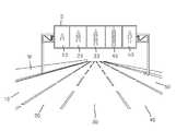
도 3은 본 발명의 일 실시예에 따른 주행 차로 정보 또는 도로 정보 식별 시스템이 적용되는 도로를 나타낸다.
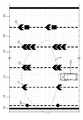
도 4는 도 3의 주행 차로 정보 또는 도로 정보 식별 시스템에서 획득한 영상 데이터를 나타낸다.
도 5는 본 발명의 다른 실시예에 따른 주행 차로 정보 또는 도로 정보 식별 시스템이 적용되는 도로를 나타낸다.
도 6은 도 5의 주행 차로 정보 또는 도로 정보 식별 시스템에서 획득한 영상 데이터를 나타낸다.
도 7 내지 도 11 각각은 본 발명의 또 다른 실시예에 따른 주행 차로 정보 또는 도로 정보 식별 시스템이 적용되는 도로를 나타낸다.
도 12는 본 발명의 일 실시예에 따른 주행 차로 정보 또는 도로 정보의 식별 방법을 나타내는 흐름도이다.1 is a block diagram schematically showing a vehicle equipped with a driving lane information or road information identification system according to an embodiment of the present invention.
FIG. 2 shows an image recognition process performed by the photographing unit and the identification unit in the driving lane information or road information identification system of FIG. 1;
FIG. 3 shows a road to which driving lane information or road information identification system according to an embodiment of the present invention is applied.
4 shows image data obtained from the driving lane information or the road information identification system of Fig.
FIG. 5 shows a road to which a driving lane information or road information identification system according to another embodiment of the present invention is applied.
FIG. 6 shows image data obtained by the driving lane information or the road information identification system of FIG. 5;
7 to 11 show roads to which driving lane information or road information identification system according to another embodiment of the present invention is applied.
12 is a flowchart illustrating a method of identifying driving lane information or road information according to an embodiment of the present invention.
이하, 첨부된 도면을 참조하여 본 발명의 바람직한 실시예를 상세히 설명하기로 한다.Hereinafter, preferred embodiments of the present invention will be described in detail with reference to the accompanying drawings.
본 발명의 실시예들은 당해 기술 분야에서 통상의 지식을 가진 자에게 본 발명을 더욱 완전하게 설명하기 위하여 제공되는 것이며, 하기 실시예는 여러 가지 다른 형태로 변형될 수 있으며, 본 발명의 범위가 하기 실시예에 한정되는 것은 아니다. 오히려, 이들 실시예는 본 개시를 더욱 충실하고 완전하게 하고, 당업자에게 본 발명의 사상을 완전하게 전달하기 위하여 제공되는 것이다.The embodiments of the present invention are described in order to more fully explain the present invention to those skilled in the art, and the following embodiments may be modified in various other forms, The present invention is not limited to the embodiment. Rather, these embodiments are provided so that this disclosure will be more faithful and complete, and will fully convey the scope of the invention to those skilled in the art.
또한, 이하의 도면에서 각 구성은 설명의 편의 및 명확성을 위하여 과장된 것이며, 도면상에서 동일 부호는 동일한 요소를 지칭한다. 본 명세서에서 사용된 바와 같이, 용어 "및/또는" 는 해당 열거된 항목 중 어느 하나 및 하나 이상의 모든 조합을 포함한다.Also, in the following drawings, each configuration is exaggerated for convenience and clarity of description, and the same reference numerals denote the same elements in the drawings. As used herein, the term "and / or" includes any and all combinations of any of the listed items.
본 명세서에서 사용된 용어는 특정 실시예를 설명하기 위하여 사용되며, 본 발명을 제한하기 위한 것이 아니다.The terminology used herein is for the purpose of describing particular embodiments only and is not intended to be limiting of the invention.
본 명세서에서 사용된 바와 같이, 단수 형태는 문맥상 다른 경우를 분명히 지적하는 것이 아니라면, 복수의 형태를 포함할 수 있다. 또한, 본 명세서에서 사용되는 경우 "포함한다(comprise)." 및/또는 "포함하는(comprising)"은 언급한 형상들, 숫자, 단계, 동작, 부재, 요소 및/또는 이들 그룹의 존재를 특정하는 것이며, 하나 이상의 다른 형상, 숫자, 동작, 부재, 요소 및 /또는 그룹들의 존재 또는 부가를 배제하는 것이 아니다.As used herein, the singular forms "a," "an," and "the" include singular forms unless the context clearly dictates otherwise. Also, "comprise" as used herein. And / or "comprising" when used herein are intended to specify the presence of stated features, integers, steps, operations, elements, elements and / And / or groups.
이하, 첨부된 도면을 참조하여 본 발명의 실시예를 상세히 설명하기로 한다.Hereinafter, embodiments of the present invention will be described in detail with reference to the accompanying drawings.
도 1은 본 발명의 일 실시예에 따른 주행 차로 정보 또는 도로 정보의 식별 시스템을 구비한 차량을 개략적으로 나타내는 블록도이고, 도 2는 도 1의 주행 차로 정보 또는 도로 정보 식별 시스템에서 촬영부 및 식별부에서 수행되는 영상 인식 과정을 나타내고, 도 3은 본 발명의 일 실시예에 따른 주행 차로 정보 또는 도로 정보 식별 시스템이 적용되는 도로를 나타내고, 도 4는 도 3의 주행 차로 정보 또는 도로 정보 식별 시스템에서 획득한 영상 데이터를 나타낸다.FIG. 1 is a block diagram schematically showing a vehicle equipped with a driving lane information or road information identification system according to an embodiment of the present invention. FIG. 2 is a block diagram of a driving lane information or road information identification system, FIG. 3 shows a road to which a driving lane information or a road information identification system according to an embodiment of the present invention is applied, and FIG. 4 shows a road lane information or a road information It shows the image data acquired by the system.
도 1 내지 도 3을 참조하면, 본 발명의 일 실시예에 따른 차량(100)의 주행 차로 정보 또는 도로 정보의 식별 시스템은 촬영부(110), 식별부(120), 제어부(130) 및 조향 장치(140)를 포함한다.1 to 3, a driving lane information or road information identification system for a
우선, 차량(100)의 주행 차로 정보 또는 도로 정보의 식별 시스템이 적용되는 도로에는 각 차로(10, 20, 30, 40, 50) 마다 상이한 주행 차로 식별 마크(11, 21, 31, 41, 51)가 형성된다.First, identification marks 11, 21, 31, 41, 51 (hereinafter, referred to as " identification marks ") are formed on the roads to which the driving- Is formed.
상세히는 1차로(10)의 중앙에 제 1 마크(11)가 형성되고, 2차로(20)의 중앙에 제 2 마크(21)가 형성되고, 3차로(30)의 중앙에 제 3 마크(31)가 형성되고, 4차로(40)의 중앙에 제 4 마크(41)가 형성되고, 갓길 차로(50)에 갓길마크(51)가 형성된다. 물론, 차로가 증가할수록 이에 대응되는 주행 차로 식별 마크가 더 형성될 수 있다.Specifically, a
또한, 중앙 분리대 혹은 중앙선(M)에 중앙선 마크(M1)가 형성된다.In addition, a center mark M1 is formed on the center separator or the center line M.
여기서, 본 발명의 도면에서 각 차로(10, 20, 30, 40, 50)는 직선 차로로 도시되어 있으나, 이는 설명의 편의를 위한 것일 뿐, 각 차로(10, 20, 30, 40, 50)가 곡선 차로로 형성될 수 있다.The
또한, 본 발명의 도면에 도시된 바와 같이 각 차로(10, 20, 30, 40, 50)에 형성된 각 주행 차로 식별 마크(11, 21, 31, 41, 51)는 차로(10, 20, 30, 40, 50)의 번호가 증가할수록 주행 차로 식별 마크(11, 21, 31, 41, 51) 내에 있는 동일한 도형의 개수가 증가하는 것이 인식하기에 바람직하지만, 각기 상이한 도형으로 형성될 수도 있다.As shown in the drawings of the present invention, each driving
촬영부(110)는 차량(100)에 외부에 설치될 수도 있고, 내부 또는 외부의 전방에 설치될 수도 있는 카메라로 구성되며, 차량(100)의 전방 범위(A)를 촬영하여, 전방 범위(A)에서 영상 데이터(B)를 획득(110a)할 수 있다. 여기서, 영상 데이터(B)는 설정된 시간(예를 들어, 1초)마다 주행 중 촬영되는 영상 중 선택된 하나의 프레임일 수 있다.The photographing
여기서, 본 발명에서 촬영부(110)의 종류 및 촬영 기법을 한정하지 않음은 물론이다.Here, it goes without saying that the type of the photographing
또한, 본 발명의 도면에서 도시된 전방 범위(A)는 설명의 편의를 위한 것일 뿐, 촬영되는 전방 범위(A)는 차량(100)에서 시각적으로 식별되는 모든 범위일 수 있으며, 도면에서 도시된 전방 범위(A)로 한정되지 않는다.Further, the front range A shown in the drawings of the present invention is only for convenience of description, and the front range A to be photographed may be all the range visually identified in the
식별부(120)는 촬영부(110)에서 획득한 영상 데이터(B)에서 배경을 분리(120a)하고, 관심영역을 설정(120b)하고, 히스토그램을 생성(120c)하고, 주행 차로 식별 마크를 인식(120d)하여, 주행 차로 정보 및 도로 정보를 식별(120e)한다.The
여기서, 주행 차로 정보라 함은 차량(100)이 주행하고 있는 차로의 정보(예를 들어, 1차로, 2차로,….)이며, 도로 정보라 함은 일반 도로 또는 고속도로 주행 중 발생하는 진입, 진출 또는 차로 변경을 요하는 도로 시설의 위치 정보 및 도로 시설 까지의 거리 정보일 수 있다.Here, the driving lane information is information on the lane on which the
이러한, 도로 시설은 차량(100)의 주행 차로 정보 또는 도로 정보의 식별 시스템에 등록 지점으로 저장된다. 여기서, 등록 지점은 교차로, 고가도로, 지하도로, 나들목, 분기점, 요금소 또는 휴게소일 수 있다.This road facility is stored as a registration point in the driving lane information of the
식별부(120)에서 영상 데이터(B)에서 배경을 분리(120a)하는 과정은, 배경 제거 알고리즘을 통해 영상 데이터(B)에서 전경에 해당하는 이미지만을 남기고, 나머지 배경에 해당하는 픽셀들은 모두 0으로 출력한다.In the process of separating the
식별부(120)에서 관심영역을 설정(120b)하는 과정은, 전경의 블럽(blob)들을 감싸는 사각형들을 구하며, 해당 사각형들을 관심 영역(C, Region of interest)으로 지정하게 되면 이것이 도로에서 주행 차로 식별 마크(M1, 11, 22, 31, 41, 51)의 관심 영역(C)이 된다. 이때, 전경의 블럽들 중 크기가 너무 작은 것들은 노이즈로 간주하여 제거할 수 있다.In the process of setting the region of
식별부(120)에서 히스토그램을 생성(120c)하는 과정은, 관심 영역(C)에서 이미지의 깊이 값의 분포를 나타내는 히스토그램(histogram)을 생성한다. 여기서, 배경이 제거되었기 때문에 관심 영역(C)에는 촬영부(110)로부터 측정된 차선 및 주행 차로 식별 마크(M1, 11, 22, 31, 41, 51)의 깊이 정보만이 포함되어 있다. 즉, 히스토그램에는 주행 차로 식별 마크(M1, 11, 22, 31, 41, 51)가 존재하는 영역에만 높은 값을 나타낸다.The process of generating the
식별부(120)에서 주행 차로 식별 마크를 인식(120d)하는 과정은, 히스토그램을 통해 주행 차로 식별 마크(M1, 11, 22, 31, 41, 51)가 존재하는 영역에만 높은 값을 나타내므로, 이러한 사실을 이용하여 생성된 히스토그램에서 최대 높이정보(local maximum)를 찾게 되면 주행 차로 식별 마크(M1, 11, 22, 31, 41, 51)를 인식할 수 있다.The process of recognizing the driving
여기서, 도시하지 않았지만, 히스토그램에서 이진화 처리를 통해 설정된 임계값(threshold)보다 밝은 픽셀들은 모두 흰색으로 표현하여, 차선 및 주행 차로 식별 마크(M1, 11, 22, 31, 41, 51)를 인식할 수도 있다.Although not shown in the figure, all the pixels brighter than the threshold value set through the binarization process in the histogram are all expressed in white, and the identification marks M1, 11, 22, 31, 41 and 51 are recognized as lanes and vehicles It is possible.
식별부(120)에서 주행 차로 정보 및 도로 정보를 식별(120e)하는 과정은, 사전에 각각의 주행 차로 식별 마크(M1, 11, 22, 31, 41, 51) 및 도로 정보 식별 마크 마다 상이한 마크를 가지며, 이러한 마크에 매칭되는 각각의 주행 차로(10, 20, 30, 40, 50) 정보 및 도로 정보가 저장되어 있으므로, 인식된 주행 차로 식별 마크(M1, 11, 22, 31, 41, 51)를 통해 차량(100)이 주행하는 주행 차로(10, 20, 30, 40, 50) 정보 및 도로 정보를 식별할 수 있다.The process of identifying the driving lane information and the road information in the
여기서, 도시하지 않았지만, 식별부(120)에서는 배경이 제거된 관심 영역(C)에서 에지(edge) 검출 기법을 이용해, 에지로 식별되는 도형을 주행 차로 정보 또는 도로 정보의 식별 시스템(100)에 저장된 주행 차로 식별 마크(M1, 11, 22, 31, 41, 51)에 매칭하여, 이에 대응되는 각각의 주행 차로(10, 20, 30, 40, 50) 정보 및 도로 정보를 식별할 수 있다.Although not shown, the
제어부(130)는 주행 차로 정보 또는 도로 정보의 식별 시스템(100)의 전반적인 동작 및 자율 주행을 제공하기 위한 차량(100)의 각 동작 장치를 제어한다.The
제어부(130)는 식별부(120)에서 식별된 차량(100)이 주행하는 주행 차로(10, 20, 30, 40, 50) 정보 및 도로 정보를 통해, 필요 시 차량(100) 조향 장치(140)를 제어할 수 있다.The
여기서, 본 발명의 일 실시예에서는 차로 변경에 대해서 기술하고 있으므로, 조향 장치(140)에 대해서만 설명하지만, 제어부(130)를 통해 차량(100)의 변속, 및 브레이크 등을 제어할 수 있음은 물론이다.Although the
즉, 차량(100)에서 필요 시 주행 차로 변경을 요청하면, 제어부(130)는 식별부(120)에서 식별된 차로 정보를 기반으로 주행 차로를 변경한다.That is, when the
여기서, 차량(100)에서 필요 시 주행 차로 변경이라 함은 일반도로 혹은 고속도로에서 교차로, 고가도로, 지하도로, 나들목, 분기점 등에서 목적지 방향 진입에 의한 차로 변경 또는 휴게소, 요금소 진입에 의한 차로 변경 등 다양한 경우일 수 있다.Herein, the change from the
다음은 도 5 및 도 6을 함께 참조하여, 본 발명의 다른 실시예에 따른 주행 차로 정보 또는 도로 정보 식별 시스템을 설명한다.Next, referring to FIG. 5 and FIG. 6 together, a driving lane information or road information identification system according to another embodiment of the present invention will be described.
도 5는 본 발명의 다른 실시예에 따른 주행 차로 정보 또는 도로 정보 식별 시스템이 적용된 도로 정보를 나타내고, 도 6은 도 5의 주행 차로 정보 또는 도로 정보 식별 시스템에서 획득한 영상 데이터를 나타낸다.FIG. 5 shows road information to which driving lane information or road information identification system according to another embodiment of the present invention is applied, and FIG. 6 shows image data obtained from the driving lane information or road information identification system of FIG.
도 3 내지 도 6을 비교 참조하면, 도 3 및 도 4에 도시된 본 발명의 일 실시예에 따른 주행 차로 정보 또는 도로 정보 식별 시스템에서의 도로에는 각 차로(10, 20, 30, 40, 50)의 중앙에 각각 상이한 주행 차로 식별 마크(11, 21, 31, 41, 51)가 형성되어 있어, 식별부(120)에서 영상 데이터(B)의 관심영역(C) 중 중심 영역에서 주행 차로 식별 마크(11, 21, 31, 41, 51)를 인식하지만, 도 5 및 도 6에 도시된 본 발명의 다른 실시예에 따른 주행 차로 정보 또는 도로 정보 식별 시스템에서의 도로에는 각 차로(10, 20, 30, 40, 50)의 일측(예를 들어, 우측) 차선에 각각 상이한 주행 차로 식별 마크(12, 22, 32, 42, 52)가 형성되어 있어, 식별부(120)에서 영상 데이터(B)의 관심영역(C) 중 일측(예를 들어, 우측) 영역에서 주행 차로 식별 마크(12, 22, 32, 42, 52)를 인식할 수 있다.3 and FIG. 6, the roads in the driving lane information or road information identification system according to the embodiment of the present invention shown in FIGS. 3 and 4 are provided with the
다음은 도 7 내지 도 11을 함께 참조하여, 본 발명의 또 다른 실시예에 따른 주행 차로 정보 또는 도로 정보 식별 시스템을 설명한다.Next, a driving lane information or road information identification system according to another embodiment of the present invention will be described with reference to FIGS. 7 to 11. FIG.
도 7 내지 도 11 각각은 본 발명의 또 다른 실시예에 따른 주행 차로 정보 또는 도로 정보 식별 시스템이 적용되는 도로를 나타낸다.7 to 11 show roads to which driving lane information or road information identification system according to another embodiment of the present invention is applied.
우선, 도 3 및 도 5를 함께 비교 참조하면, 도 3 및 도 5에서는 도로에서 각 차로(10, 20, 30, 40, 50) 상에 주행 차로 식별 마크(11, 12, 21, 22, 31, 32, 41, 42, 51, 52)가 직접 형성되어 있어, 식별부(120)에서 영상 데이터(B)의 관심영역(C)을 도로상에 맞추지만, 도 7의 도로 정보에서는 도로의 상부에 형성된 표지판(S)에 각 차로(10, 20, 30, 40, 50)에 대응되는 주행 차로 식별 마크(13, 23, 33, 43, 53)가 형성되어, 식별부(120)에서 도로 상부에 위치한 표지판(S)에 관심영역(C)을 맞출 수 있다.3 and Fig. 5, the identification marks 11, 12, 21, 22, 31 (refer to Fig. 3 and Fig. 5) are displayed on the
여기서, "대응된다." 함은 각 차로(10, 20, 30, 40, 50)의 바로 상부에 형성되는 것을 의미이다.Here, "corresponding" Means that it is formed directly above each
우선, 도 8의 도로에서는 차량(100)이 편도 3차로 도로를 주행하고 있으며, 3차로(30) 주행 중간에 나들목 중 진출 램프(60)가 위치한다. 또한, 3차로(30)의 우측 차선에 진출 램프(60)의 위치를 알려주는 도로 정보 식별 마크(61, 62, 63)가 형성된다. 또한, 차량(100)은 2차로(20)로 주행 중이며, 여기서, 전술한 바와 같이 차량(100)의 주행 차로 정보 또는 도로 정보의 식별 시스템의 촬영부(110) 및 식별부(120)를 통해 2차로(20)의 제 2 마크(21)를 인식하며, 차량(100)이 2차로(20)로 주행 중인 것을 식별한다.First, in the road in Fig. 8, the
여기서, 도로 정보 식별 마크(61, 62, 63)는 차선 중 하나에 형성된 것으로 도시되어 있으나, 이는 설명의 편의를 위한 것일 뿐, 도로 정보 식별 마크(61, 62, 63)가 별도의 표지판(미도시)에 형성될 수도 있다.Although the road information identification marks 61, 62 and 63 are shown as being formed in one of the lanes, only the road information identification marks 61, 62 and 63 are shown as separate signs (not shown) As shown in FIG.
이때, 차량(100)에서 목적지 방향의 진출 램프(60)로 진출할 필요가 있을 경우, 제어부(130)는 식별부(120)에서 인식되는 도로 정보 식별 마크(61, 62, 63) 정보를 기반으로 차량(100)을 제어하여, 진출 램프(60)로 진출한다.At this time, when it is necessary to advance from the
즉, 차량(100)의 촬영부(110)에서는 전방 범위(A)에서 영상 데이터(B)를 획득(110a)하고, 식별부(120)는 전술한 영상 인식 과정(120a ~ 120e)에 따라 영상 데이터(B)에서 도로 정보 식별 마크(61, 62, 63)를 인식하며, 이를 통해 전방에 진출 램프(60)가 위치한 것을 식별한다.That is, in the photographing
또한, 도로 정보 식별 마크(61, 62, 63)는 진출 램프(60)까지의 거리를 안내해주는 거리 안내 마크(61, 62, 63)로 구성되며, 진출 램프(60)까지의 거리가 100m인 곳에 형성된 제 1 거리 안내 마크(61), 진출 램프(60)까지의 거리가 500m인 곳에 형성된 제 2 거리 안내 마크(62) 및 진출 램프(60)까지의 거리가 1,000m인 곳에 형성된 제 3 거리 안내 마크(63)를 포함한다.The road information identification marks 61, 62 and 63 are composed of distance guide marks 61, 62 and 63 for guiding the distance to the
여기서, 이러한 거리 수치는 본 발명에서 설명의 편의를 위한 것일 뿐, 다양한 실시로 변경 가능함은 물론이다.Here, such distance values are for convenience of explanation in the present invention, and it goes without saying that they can be changed in various ways.
또한, 본 발명의 도면에 도시된 바와 같이 각 거리 안내 마크(61, 62, 63)는 진출 램프(60)에 인접할수록 거리 안내 마크(61, 62, 63) 내에 있는 도형의 개수가 감소하는 것이 인식하기에 바람직하지만, 반대로 증가할 수도 있고, 각기 상이한 도형으로 형성될 수도 있다.As shown in the drawings of the present invention, the number of figures in the distance guide marks 61, 62 and 63 decreases as the distance guide marks 61, 62 and 63 are adjacent to the
따라서, 식별부(120)에서는 각각의 거리 안내 마크(61, 62, 63)를 인식하여, 진출 램프(60)까지의 거리를 식별할 수 있다. 또한, 식별부(120)에서는 진출 램프(60)의 식별 정보를 제어부(130)에 전달하며, 제어부(130)에서 차량(100)을 제어하여, 진출 램프(60)로 진출하기 위해 차로(10, 20, 30) 변경을 적절하게 할 수 있도록 한다.Therefore, the
도 9의 도로에서는 차량(100)이 편도 3차로 도로를 주행하고 있으며, 3차로(30) 주행 중간에 나들목 중 진입 램프(70)가 위치한다. 또한, 1차로(10)의 좌측 차선에 진입 램프(70)의 위치를 알려주는 도로 정보 식별 마크(71, 72, 73)가 형성된다.In the road shown in Fig. 9, the
또한, 차량(100)은 1차로(10)로 주행 중이며, 여기서, 전술한 바와 같이 차량(100)의 주행 차로 정보 또는 도로 정보의 식별 시스템의 촬영부(110) 및 식별부(120)를 통해 1차로(10)의 제 1 마크(11)를 인식하며, 차량(100)이 1차로(10)로 주행 중인 것을 식별한다.The
여기서, 도로 정보 식별 마크(71, 72, 73)는 차선 중 하나에 형성된 것으로 도시되어 있으나, 이는 설명의 편의를 위한 것일 뿐, 도로 정보 식별 마크(61, 62, 63)가 별도의 표지판(미도시)에 형성될 수도 있다.Although the road information identification marks 71, 72, and 73 are shown as being formed in one of the lanes, only the road information identification marks 61, 62, and 63 are shown as separate signs As shown in FIG.
이때, 차량(100)의 전방이 진입 램프(70)에서 차량(200)이 진입하는 상황에 대비하여, 제어부(130)는 식별부(120)에서 인식되는 도로 정보 식별 마크(71, 72, 73) 정보를 기반으로 차량(100)을 제어하여, 감속하거나 2차로(20)로 차로를 변경한다.At this time, in response to a situation in which the
즉, 차량(100)의 촬영부(110)에서는 전방 범위(A)에서 영상 데이터(B)를 획득(110a)하고, 식별부(120)는 전술한 영상 인식 과정(120a ~ 120e)에 따라 영상 데이터(B)에서 도로 정보 식별 마크(71, 72, 73)를 인식하며, 이를 통해 전방에 진입 램프(70)가 위치한 것을 식별한다.That is, in the photographing
또한, 도로 정보 식별 마크(71, 72, 73)는 진입 램프(70)까지의 거리를 안내해주는 거리 안내 마크(71, 72, 73)로 구성되며, 진입 램프(70)까지의 거리가 100m인 곳에 형성된 제 1 거리 안내 마크(71), 진입 램프(70)까지의 거리가 500m인 곳에 형성된 제 2 거리 안내 마크(72) 및 진입 램프(70)까지의 거리가 1,000m인 곳에 형성된 제 3 거리 안내 마크(73)를 포함한다.The road information identification marks 71, 72 and 73 are made up of distance guide marks 71, 72 and 73 for guiding the distance to the
여기서, 이러한 거리 수치는 본 발명에서 설명의 편의를 위한 것일 뿐, 다양한 실시로 변경 가능함은 물론이다.Here, such distance values are for convenience of explanation in the present invention, and it goes without saying that they can be changed in various ways.
또한, 본 발명의 도면에 도시된 바와 같이 각 거리 안내 마크(71, 72, 73)는 진입 램프(70)에 인접할수록 거리 안내 마크(71, 72, 73) 내에 있는 도형의 개수가 감소하는 것이 인식하기에 바람직하지만, 반대로 증가할 수도 있고, 각기 상이한 도형으로 형성될 수도 있다.As shown in the drawings of the present invention, the distance guide marks 71, 72, and 73 are formed such that the number of figures in the distance guide marks 71, 72, It may be increased, or may be formed in different shapes.
따라서, 식별부(120)에서는 각각의 거리 안내 마크(71, 72, 73)를 인식하여, 진입 램프(70)까지의 거리를 식별할 수 있다. 또한, 식별부(120)에서는 진입 램프(70) 식별 정보를 제어부(130)에 전달하며, 제어부(130)에서 차량(100)을 제어하여, 적절히 감속하거나 2차로(20)로 차로를 변경할 수 있도록 한다.Therefore, the
도 10의 도로에서는 차량(100)이 편도 2차로 도로를 주행하고 있으며, 2차로(20) 주행 중간에 분기점(80)이 위치한다. 또한, 1차로(10)의 우측 차선에 분기점(80)의 위치를 알려주는 도로 정보 식별 마크(81, 82, 83)가 형성된다.On the road in Fig. 10, the
또한, 차량(100)은 2차로(20)로 주행 중이며, 여기서, 전술한 바와 같이 차량(100)의 주행 차로 정보 또는 도로 정보의 식별 시스템의 촬영부(110) 및 식별부(120)를 통해 2차로(20)의 제 2 마크(21)를 인식하며, 차량(100)이 2차로(20)로 주행 중인 것을 식별한다.The
여기서, 도로 정보 식별 마크(81, 82, 83)는 차선 중 하나에 형성된 것으로 도시되어 있으나, 이는 설명의 편의를 위한 것일 뿐, 도로 정보 식별 마크(61, 62, 63)가 별도의 표지판(미도시)에 형성될 수도 있다.Although the road information identification marks 81, 82, and 83 are shown as being formed in one of the lanes, the road information identification marks 61, 62, and 63 are shown as separate signs (not shown) As shown in FIG.
이때, 차량(100)에서 목적지 방향의 분기점(80)으로 진입할 필요가 있을 경우, 제어부(130)는 식별부(120)에서 인식되는 도로 정보 식별 마크(81, 82, 83) 정보를 기반으로 차량(100)을 제어하여, 분기점(80)으로 진입한다.At this time, when it is necessary to enter the
즉, 차량(100)의 촬영부(110)에서는 전방 범위(A)에서 영상 데이터(B)를 획득(110a)하고, 식별부(120)는 전술한 영상 인식 과정(120a ~ 120e)에 따라 영상 데이터(B)에서 도로 정보 식별 마크(81, 82, 83)를 인식하며, 이를 통해 전방에 분기점(80)이 위치한 것을 식별한다.That is, in the photographing
또한, 도로 정보 식별 마크(81, 82, 83)는 분기점(80)까지의 거리를 안내해주는 거리 안내 마크(81, 82, 83)로 구성되며, 분기점(80)까지의 거리가 100m인 곳에 형성된 제 1 거리 안내 마크(81), 분기점(80)까지의 거리가 500m인 곳에 형성된 제 2 거리 안내 마크(82) 및 분기점(80)까지의 거리가 1,000m인 곳에 형성된 제 3 거리 안내 마크(83)를 포함한다.The road information identification marks 81, 82 and 83 are formed of distance guide marks 81, 82 and 83 for guiding the distance to the
여기서, 이러한 거리 수치는 본 발명에서 설명의 편의를 위한 것일 뿐, 다양한 실시로 변경 가능함은 물론이다.Here, such distance values are for convenience of explanation in the present invention, and it goes without saying that they can be changed in various ways.
또한, 본 발명의 도면에 도시된 바와 같이 각 거리 안내 마크(81, 82, 83)는 분기점(80)에 인접할수록 거리 안내 마크(81, 82, 83) 내에 있는 도형의 개수가 감소하는 것이 인식하기에 바람직하지만, 반대로 증가할 수도 있고, 각기 상이한 도형으로 형성될 수도 있다.As shown in the drawings of the present invention, it is recognized that the number of figures in the distance guide marks 81, 82, 83 decreases as the distance guide marks 81, 82, But may be increased inversely, or may be formed in different shapes.
따라서, 식별부(120)에서는 각각의 거리 안내 마크(81, 82, 83)를 인식하여, 분기점(80)까지의 거리를 식별할 수 있다. 또한, 식별부(120)에서는 분기점(80) 식별 정보를 제어부(130)에 전달하며, 제어부(130)에서 차량(100)을 제어하여, 분기점(80) 중 목적지 방향(80a, 80b)으로 진입하기 위해 차로(10, 20) 변경을 적절하게 할 수 있도록 한다.Therefore, the
도 11의 도로에서는 차량(100)이 편도 3차로 도로를 주행하고 있으며, 3차로(30) 주행 중간에 휴게소(90) 진입로가 위치한다. 또한, 3차로(30)의 우측 차선에 휴게소(90)의 위치를 알려주는 도로 정보 식별 마크(91, 92, 93)가 형성된다.In the road shown in Fig. 11, the
또한, 차량(100)은 2차로(20)로 주행 중이며, 여기서, 전술한 바와 같이 차량(100)의 주행 차로 정보 또는 도로 정보의 식별 시스템의 촬영부(110) 및 식별부(120)를 통해 2차로(20)의 제 2 마크(21)를 인식하며, 차량(100)이 2차로(20)로 주행 중인 것을 식별한다.The
여기서, 도로 정보 식별 마크(91, 92, 93)는 차선 중 하나에 형성된 것으로 도시되어 있으나, 이는 설명의 편의를 위한 것일 뿐, 도로 정보 식별 마크(61, 62, 63)가 별도의 표지판(미도시)에 형성될 수도 있다.Although the road information identification marks 91, 92 and 93 are shown as being formed in one of the lanes, only the road information identification marks 61, 62 and 63 are shown as separate signs As shown in FIG.
이때, 차량(100)에서 휴게소(90)로 진출할 필요가 있을 경우, 제어부(130)는 식별부(120)에서 인식되는 도로 정보 식별 마크(91, 92, 93) 정보를 기반으로 차량(100)을 제어하여, 휴게소(90)로 진출한다.At this time, when it is necessary to advance from the
즉, 차량(100)의 촬영부(110)에서는 전방 범위(A)에서 영상 데이터(B)를 획득(110a)하고, 식별부(120)는 전술한 영상 인식 과정(120a ~ 120e)에 따라 영상 데이터(B)에서 도로 정보 식별 마크(91, 92, 93)를 인식하며, 이를 통해 전방에 휴게소(90)가 위치한 것을 식별한다.That is, in the photographing
또한, 도로 정보 식별 마크(91, 92, 93)는 휴게소(90)까지의 거리를 안내해주는 거리 안내 마크(91, 92, 93)로 구성되며, 휴게소(90)까지의 거리가 100m인 곳에 형성된 제 1 거리 안내 마크(91), 휴게소(90)까지의 거리가 500m인 곳에 형성된 제 2 거리 안내 마크(92) 및 휴게소(90)까지의 거리가 1,000m인 곳에 형성된 제 3 거리 안내 마크(93)를 포함한다.The road information identification marks 91, 92 and 93 are composed of distance guide marks 91, 92 and 93 for guiding the distance to the
여기서, 이러한 거리 수치는 본 발명에서 설명의 편의를 위한 것일 뿐, 다양한 실시로 변경 가능함은 물론이다.Here, such distance values are for convenience of explanation in the present invention, and it goes without saying that they can be changed in various ways.
또한, 본 발명의 도면에 도시된 바와 같이 각 거리 안내 마크(91, 92, 93)는 휴게소(90)에 인접할수록 거리 안내 마크(91, 92, 93) 내에 있는 도형의 개수가 감소하는 것이 인식하기에 바람직하지만, 반대로 증가할 수도 있고, 각기 상이한 도형으로 형성될 수도 있다.As shown in the drawings of the present invention, it is recognized that the number of the figures in the distance guide marks 91, 92, 93 decreases as the distance guide marks 91, 92, 93 are closer to the
따라서, 식별부(120)에서는 각각의 거리 안내 마크(91, 92, 93)를 인식하여, 휴게소(90)까지의 거리를 식별할 수 있다. 또한, 식별부(120)에서는 휴게소(90) 식별 정보를 제어부(130)에 전달하며, 제어부(130)에서 차량(100)을 제어하여, 휴게소(90)로 진출하기 위해 차로(10, 20, 30) 변경을 적절하게 할 수 있도록 한다.Therefore, the
다음은 도 12를 함께 참조하여, 본 발명의 일 실시예에 따른 주행 차로 정보 또는 도로 정보 식별 방법을 설명한다.Next, referring to FIG. 12, a driving lane information or a road information identification method according to an embodiment of the present invention will be described.
도 12는 본 발명의 일 실시예에 따른 주행 차로 정보 또는 도로 정보의 식별 방법을 나타내는 흐름도이다.12 is a flowchart illustrating a method of identifying driving lane information or road information according to an embodiment of the present invention.
본 발명의 일 실시예에 따른 주행 차로 정보 또는 도로 정보 식별 방법은 영상 데이터 획득 단계(S10), 식별 마크 인식 단계(S20), 주행 차로 정보 또는 도로 정보 식별 단계(S30) 및 차량 제어 단계(S40)를 포함한다.The driving lane information or the road information identifying method according to an embodiment of the present invention may include a step of acquiring image data (S10), an identification mark recognition step (S20), a driving lane information or road information identification step (S30) ).
우선, 영상 데이터 획득 단계(S10)에서는 상술한 바와 같이, 차량의 내부 또는 외부에 설치된 촬영부(110)를 통해, 차량(100)의 전방 범위(A)를 촬영하여, 전방 범위(A)에서 영상 데이터(B)를 획득한다. 여기서, 영상 데이터(B)는 설정된 시간(예를 들어, 1초)마다 주행 중 촬영되는 영상 중 선택된 하나의 프레임일 수 있다. 여기서, 본 발명에서 촬영부(110)의 종류 및 촬영 기법을 한정하지 않음은 물론이다. 또한, 본 발명의 도면에서 도시된 전방 범위(A)는 설명의 편의를 위한 것일 뿐, 촬영되는 전방 범위(A)는 차량(100)에서 시각적으로 식별되는 모든 범위일 수 있으며, 도면에서 도시된 전방 범위(A)로 한정되지 않는다.First, in the image data acquisition step S10, the front range A of the
이후, 식별 마크 인식 단계(S20)에서는 상술한 바와 같이 영상 데이터(B)에서 존재하는 차로(10, 20, 30, 40, 50), 차선, 혹은 표지판(S)에 형성된 다수의 주행 차로 식별 마크 및 도로 정보 식별 마크 중 적어도 하나 이상을 인식한다. 다수의 주행 차로 식별 마크 및 도로 정보 식별 마크를 인식하는 방법은 상술한 바와 같이 구성될 수 있으며, 여기서 상세한 설명은 생략한다.In the identification mark recognition step S20, as described above, a plurality of driving
이후, 주행 차로 정보 또는 도로 정보 식별 단계(S30)에서는 사전에 각각의 주행 차로 식별 마크 및 도로 정보 식별 마크마다 상이한 마크를 가지며, 이러한 마크에 매칭되는 각각의 주행 차로(10, 20, 30, 40, 50) 정보 및 도로 정보가 저장되어 있으므로, 인식된 주행 차로 식별 마크(M1, 11, 22, 31, 41, 51)와 도로 정보 식별 마크를 통해 차량(100)이 주행하는 주행 차로(10, 20, 30, 40, 50) 정보 및/또는 도로 정보를 식별할 수 있다.Thereafter, in the driving lane information or road information identification step S30, each driving
이후, 차량 제어 단계(S40)에서는 상술한 바와 같이, 제어부(130)에서 주행 차로 정보 또는 도로 정보를 기반으로, 차량(100)의 각 동작 장치를 제어한다. 즉, 차량 제어 단계(S30)에서 제어부(130)는 주행 차로 정보 또는 도로 정보 식별 단계(S30)에서 식별된 차량(100)이 주행하는 주행 차로(10, 20, 30, 40, 50) 정보 및/또는 도로 정보를 통해, 필요 시 차량(100) 조향 장치(140)를 제어할 수 있다.Then, in the vehicle control step S40, the
이를 통해, 제어부(130)에서는 차량(100)의 변속, 및 브레이크 등을 제어하여, 차량(100)에서 필요 시 주행 차로 변경을 요청하면, 식별된 차로 정보 및/또는 도로 정보를 기반으로 주행 차로를 변경한다.The
이상에서 설명한 것은 본 발명에 따른 주행 차로 정보 또는 도로 정보 식별 시스템 및 이를 이용한 식별 방법을 실시하기 위한 하나의 실시예에 불과한 것으로서, 본 발명은 한 실시예에 한정되지 않고, 이하의 특허청구범위에서 청구하는 바와 같이 본 발명의 요지를 벗어남이 없이 당해 발명이 속하는 분야에서 통상의 지식을 가진 자라면 누구든지 다양한 변경 실시가 가능한 범위까지 본 발명의 기술적 정신이 있다고 할 것이다.It is to be understood that the present invention is not limited to the above-described embodiment, but may be embodied in many different forms and should not be construed as being limited to the embodiments set forth herein, It will be understood by those of ordinary skill in the art that various changes in form and details may be made therein without departing from the spirit and scope of the invention as defined in the appended claims.
10, 20, 30, 40, 50: 차로11, 21, 31, 41, 51: 주행 차로 식별 마크
61, 62, 63: 도로 정보 식별 마크
100: 차량110: 촬영부
120: 식별부130: 제어부
140: 조향 장치10, 20, 30, 40, 50:
61, 62, 63: road information identification mark
100: vehicle 110: photographing unit
120: Identification unit 130:
140: Steering device
Claims (15)
Translated fromKorean상기 차량 전방의 영상 데이터를 획득하는 촬영부;
상기 영상 데이터를 통해 상기 차량의 주행 차로 정보 및 도로 정보를 식별하는 식별부; 및
식별된 상기 차량의 주행 차로 정보 또는 도로 정보에 따라 상기 차량의 주행 속도 및 주행 방향을 제어하는 제어부; 를 포함하고,
상기 도로상에는 주행 차로 식별 마크 및 도로 정보 식별 마크 중 적어도 하나가 형성되고,
상기 식별부는 상기 주행 차로 식별 마크와 상기 도로 정보 식별 마크 중 적어도 하나를 인식하여, 상기 차량의 주행 차로 정보 또는 도로 정보를 식별하고,
상기 주행 차로 식별 마크는
상기 도로 중 중앙선 또는 중앙 분리대에 형성된 중앙선 마크;
상기 도로 중 1차로에 형성된 제 1 마크; 및
상기 도로 중 2차로에 형성된 제 2 마크를 포함하고,
상기 식별부는
상기 영상 데이터에서 상기 제 1 마크를 인식하면, 상기 차량이 상기 1차로로 주행 중인 것으로 식별하고,
상기 영상 데이터에서 상기 제 2 마크를 인식하면, 상기 차량이 상기 2차로로 주행 중인 것으로 식별하는 것을 특징으로 하는 주행 차로 정보 또는 도로 정보 식별 시스템.
A driving-lane information or road information identification system for a vehicle traveling at least on a road more than one way,
A photographing unit for obtaining image data of the front of the vehicle;
An identification unit for identifying driving lane information and road information of the vehicle through the image data; And
A control unit for controlling the running speed and running direction of the vehicle according to the driving lane information or the road information of the identified vehicle; Lt; / RTI >
At least one of an identification mark and a road information identification mark is formed on the road,
Wherein the identification unit recognizes at least one of the driving lane mark and the road information identification mark to identify driving lane information or road information of the vehicle,
The driving lane identification mark
A center line mark formed on a center line or a median line of the road;
A first mark formed on a first one of the roads; And
And a second mark formed on a second lane of the road,
The identification unit
Recognizes the first mark in the image data, identifies the vehicle as being traveling in the primary direction,
And recognizes the second mark in the image data, identifies that the vehicle is traveling in the second lane.
상기 중앙선 마크, 상기 제 1 마크 및 상기 제 2 마크는 서로 상이한 것을 특징으로 하는 주행 차로 정보 또는 도로 정보 식별 시스템.
The method according to claim 1,
Wherein the center mark, the first mark, and the second mark are different from each other.
상기 도로에서 차로의 번호가 증가할수록,
상기 주행 차로 식별 마크에 포함된 도형의 개수가 증가하는 것을 특징으로 하는 주행 차로 정보 또는 도로 정보 식별 시스템.
The method of claim 3,
As the number of lanes on the road increases,
And the number of figures included in the driving lane identification mark increases.
상기 제 1 마크는 상기 1차로 중앙에 형성되고,
상기 제 2 마크는 상기 2차로 중앙에 형성된 것을 특징으로 하는 주행 차로 정보 또는 도로 정보 식별 시스템.
5. The method of claim 4,
Wherein the first mark is formed at the center in the primary direction,
And the second mark is formed at the center of the second road.
상기 제 1 마크는 상기 1차로 일측 차선에 형성되고,
상기 제 2 마크는 상기 2차로 일측 차선에 형성된 것을 특징으로 하는 주행 차로 정보 또는 도로 정보 식별 시스템.
5. The method of claim 4,
Wherein the first mark is formed in the primary lane,
And the second mark is formed in the second lane on one side of the lane.
상기 도로 상부에 배치되며, 상기 제 1 마크 및 상기 제 2 마크가 형성된 표지판을 더 포함하고,
상기 제 1 마크는 상기 1차로 상부에 형성되고,
상기 제 2 마크는 상기 2차로 상부에 형성된 것을 특징으로 하는 주행 차로 정보 또는 도로 정보 식별 시스템.
5. The method of claim 4,
Further comprising a sign disposed on the road and formed with the first mark and the second mark,
Wherein the first mark is formed on the primary side,
And the second mark is formed on an upper portion of the second road.
상기 도로 정보는 등록 지점의 위치 정보 및 거리 정보이며,
상기 등록 지점은 교차로, 고가도로, 지하도로, 나들목, 분기점, 요금소 또는 휴게소이고,
상기 도로 정보 식별 마크는
상기 등록 지점마다 상이한 도형으로 형성된 것을 특징으로 하는 주행 차로 정보 또는 도로 정보 식별 시스템.
The method according to claim 1,
The road information is location information and distance information of the registration point,
The registration point is an intersection, an overpass, an underpass, a junction, a branch point, a tollgate or rest area,
The road information identification mark
Wherein each of the registration points is formed in a different graphic form.
상기 도로 정보 식별 마크는
상기 등록 지점 중 적어도 하나까지의 거리를 안내하는 거리 안내 마크를 포함하고,
상기 식별부는
상기 영상 데이터에서 상기 거리 안내 마크를 인식하여, 상기 차량의 주행 전방에 위치한 상기 등록 지점까지의 거리를 식별하는 것을 특징으로 하는 주행 차로 정보 또는 도로 정보 식별 시스템.
9. The method of claim 8,
The road information identification mark
And a distance guide mark for guiding a distance to at least one of the registration points,
The identification unit
Recognizes the distance information mark in the image data, and identifies the distance to the registration point located in front of the vehicle.
상기 거리 안내 마크는
상기 등록 지점까지의 일정거리별로 상이하게 형성되며,
상기 등록 지점에 인접한 상기 거리 안내 마크일수록,
상기 거리 안내 마크에 포함된 도형의 개수가 증가하거나 감소하는 것을 특징으로 하는 주행 차로 정보 또는 도로 정보 식별 시스템.
10. The method of claim 9,
The distance guide mark
The registration points being different from each other by a predetermined distance,
The distance information mark adjacent to the registration point,
Wherein the number of figures included in the distance guidance mark is increased or decreased.
상기 식별부는
상기 영상 데이터에서 관심 영역을 설정하고, 상기 관심 영역에서 상기 식별 마크를 인식하는 것을 특징으로 하는 주행 차로 정보 또는 도로 정보 식별 시스템.
The method according to claim 1,
The identification unit
And sets the region of interest in the image data and recognizes the identification mark in the region of interest.
상기 식별부는
상기 영상 데이터에서 배경을 분리하고,
배경을 분리한 상기 영상 데이터에서 상기 관심 영역을 설정하는 것을 특징으로 하는 주행 차로 정보 또는 도로 정보 식별 시스템.
12. The method of claim 11,
The identification unit
Separating the background from the image data,
And sets the ROI in the image data in which the background is separated.
상기 식별부는
상기 관심 영역에서 히스토그램(histogram)을 생성하고,
상기 히스토그램을 통해 상기 식별 마크를 인식하는 것을 특징으로 하는 주행 차로 정보 또는 도로 정보 식별 시스템.
13. The method of claim 12,
The identification unit
Generating a histogram in the region of interest,
And the identification mark is recognized through the histogram.
상기 식별부는
상기 관심 영역에서 에지(edge) 검출 기법을 이용하여, 상기 식별 마크를 인식하는 것을 특징으로 하는 주행 차로 정보 또는 도로 정보 식별 시스템.
13. The method of claim 12,
The identification unit
And recognizing the identification mark using an edge detection technique in the area of interest.
상기 차량 전방의 영상 데이터를 획득하는 단계;
상기 영상 데이터에서 주행 차로 식별 마크 및 도로 정보 식별 마크 중 적어도 하나를 인식하는 단계;
상기 주행 차로 식별 마크에 대응되는 주행 차로 정보 또는 도로 정보 식별 마크에 대응되는 도로 정보를 식별하는 단계; 및
상기 주행 차로 정보 또는 도로 정보에 따라 상기 차량의 주행 속도 및 주행 방향을 제어하는 단계; 를 포함하는 것을 특징으로 하는 주행 차로 정보 또는 도로 정보 식별 방법.A driving lane information or road information identification method using traveling lane information or a road information identification system according to any one of claims 1 and 3 to 14,
Obtaining image data of the vehicle ahead;
Recognizing at least one of a driving lane identification mark and a road information identification mark from the image data;
Identifying driving lane information corresponding to the driving lane identification mark or road information corresponding to the road information identification mark; And
Controlling the traveling speed and traveling direction of the vehicle according to the driving lane information or the road information; Wherein the road information includes at least one of road information and road information.
Priority Applications (1)
| Application Number | Priority Date | Filing Date | Title |
|---|---|---|---|
| KR1020160047358AKR101659251B1 (en) | 2016-04-19 | 2016-04-19 | Discernment system for driving lane data or road information and discernment method using the same |
Applications Claiming Priority (1)
| Application Number | Priority Date | Filing Date | Title |
|---|---|---|---|
| KR1020160047358AKR101659251B1 (en) | 2016-04-19 | 2016-04-19 | Discernment system for driving lane data or road information and discernment method using the same |
Publications (1)
| Publication Number | Publication Date |
|---|---|
| KR101659251B1true KR101659251B1 (en) | 2016-09-23 |
Family
ID=57047550
Family Applications (1)
| Application Number | Title | Priority Date | Filing Date |
|---|---|---|---|
| KR1020160047358AActiveKR101659251B1 (en) | 2016-04-19 | 2016-04-19 | Discernment system for driving lane data or road information and discernment method using the same |
Country Status (1)
| Country | Link |
|---|---|
| KR (1) | KR101659251B1 (en) |
Cited By (5)
| Publication number | Priority date | Publication date | Assignee | Title |
|---|---|---|---|---|
| KR20190100524A (en)* | 2018-02-08 | 2019-08-29 | 주식회사 만도 | Driving assistance system and method for automatically putting vehicle into rest area on highway |
| KR20190115540A (en)* | 2018-03-23 | 2019-10-14 | 현대모비스 주식회사 | Apparatus for determining position of vehicle and method thereof |
| CN111785033A (en)* | 2020-06-28 | 2020-10-16 | 北京百度网讯科技有限公司 | Method, device, device and storage medium for vehicle driving prompt |
| WO2021225184A1 (en)* | 2020-05-03 | 2021-11-11 | Park Woowoong | Road markings of road lanes (solid lines, dotted lines) for preventing reverse driving |
| KR20220137409A (en)* | 2021-04-02 | 2022-10-12 | 허완철 | Method and system for providing vehicle driving inforamtion using digital lanes |
Citations (4)
| Publication number | Priority date | Publication date | Assignee | Title |
|---|---|---|---|---|
| KR20110048798A (en)* | 2009-11-03 | 2011-05-12 | 한국전자통신연구원 | Steering Control Device and Method Using Landmark |
| KR101217594B1 (en)* | 2012-08-16 | 2013-01-03 | 주식회사 피엘케이 테크놀로지 | Route change judgement system using image recognition information and its method |
| KR20140087860A (en)* | 2012-12-31 | 2014-07-09 | 현대자동차주식회사 | Current Lane Detecting Method |
| KR20150049529A (en)* | 2013-10-30 | 2015-05-08 | 인하대학교 산학협력단 | Apparatus and method for estimating the location of the vehicle |
- 2016
- 2016-04-19KRKR1020160047358Apatent/KR101659251B1/enactiveActive
Patent Citations (4)
| Publication number | Priority date | Publication date | Assignee | Title |
|---|---|---|---|---|
| KR20110048798A (en)* | 2009-11-03 | 2011-05-12 | 한국전자통신연구원 | Steering Control Device and Method Using Landmark |
| KR101217594B1 (en)* | 2012-08-16 | 2013-01-03 | 주식회사 피엘케이 테크놀로지 | Route change judgement system using image recognition information and its method |
| KR20140087860A (en)* | 2012-12-31 | 2014-07-09 | 현대자동차주식회사 | Current Lane Detecting Method |
| KR20150049529A (en)* | 2013-10-30 | 2015-05-08 | 인하대학교 산학협력단 | Apparatus and method for estimating the location of the vehicle |
Cited By (8)
| Publication number | Priority date | Publication date | Assignee | Title |
|---|---|---|---|---|
| KR20190100524A (en)* | 2018-02-08 | 2019-08-29 | 주식회사 만도 | Driving assistance system and method for automatically putting vehicle into rest area on highway |
| KR102438230B1 (en)* | 2018-02-08 | 2022-08-31 | 주식회사 에이치엘클레무브 | Highway rest area automatic entry support system and method |
| KR20190115540A (en)* | 2018-03-23 | 2019-10-14 | 현대모비스 주식회사 | Apparatus for determining position of vehicle and method thereof |
| KR102425346B1 (en)* | 2018-03-23 | 2022-07-27 | 현대모비스 주식회사 | Apparatus for determining position of vehicle and method thereof |
| WO2021225184A1 (en)* | 2020-05-03 | 2021-11-11 | Park Woowoong | Road markings of road lanes (solid lines, dotted lines) for preventing reverse driving |
| CN111785033A (en)* | 2020-06-28 | 2020-10-16 | 北京百度网讯科技有限公司 | Method, device, device and storage medium for vehicle driving prompt |
| KR20220137409A (en)* | 2021-04-02 | 2022-10-12 | 허완철 | Method and system for providing vehicle driving inforamtion using digital lanes |
| KR102500861B1 (en)* | 2021-04-02 | 2023-02-17 | 허완철 | Method and system for providing vehicle driving inforamtion using digital lanes |
Similar Documents
| Publication | Publication Date | Title |
|---|---|---|
| US11727692B2 (en) | Detection of emergency vehicles | |
| KR101659251B1 (en) | Discernment system for driving lane data or road information and discernment method using the same | |
| US8005615B2 (en) | Navigation system | |
| CN111194459B (en) | Evaluation of autopilot functions and road recognition in different processing phases | |
| JP7222799B2 (en) | ROAD TYPE DETERMINATION DEVICE AND DRIVING ASSIST DEVICE | |
| KR100819047B1 (en) | Intersection Centerline Prediction Device and Method | |
| JP6984379B2 (en) | Road structure data generator | |
| US20060233424A1 (en) | Vehicle position recognizing device and vehicle position recognizing method | |
| CN104276075B (en) | Method for controlling the light distribution of headlight before motor vehicles | |
| JP4914160B2 (en) | Vehicle control device | |
| US9257045B2 (en) | Method for detecting a traffic lane by means of a camera | |
| JP4859760B2 (en) | Car navigation apparatus, road sign recognition method and program | |
| KR101265110B1 (en) | Steering control leading apparatus using landmark and method thereby | |
| US20150371095A1 (en) | Method and Apparatus for Determining a Road Condition | |
| CN102208035A (en) | Image processing system and position measurement system | |
| US11914041B2 (en) | Detection device and detection system | |
| US9835468B2 (en) | Entry detection apparatus and entry detection method | |
| KR20190115503A (en) | Lane for autonomous driving and lane keeping assist system using this same | |
| CN108428358B (en) | Lane cognitive system applied to navigation and method thereof | |
| JP4775658B2 (en) | Feature recognition device, vehicle position recognition device, navigation device, feature recognition method | |
| KR20190064228A (en) | Apparatus and method of providing information of traffic lanes using image sensing and vehicle control method using the same | |
| WO2018030103A1 (en) | Displayed content recognition device and vehicle control device | |
| KR20170082374A (en) | Lane detection apparatus | |
| KR101706455B1 (en) | Road sign detection-based driving lane estimation method and apparatus | |
| CN115769286A (en) | Image processing apparatus |
Legal Events
| Date | Code | Title | Description |
|---|---|---|---|
| PA0109 | Patent application | St.27 status event code:A-0-1-A10-A12-nap-PA0109 | |
| PA0201 | Request for examination | St.27 status event code:A-1-2-D10-D11-exm-PA0201 | |
| PA0302 | Request for accelerated examination | St.27 status event code:A-1-2-D10-D17-exm-PA0302 St.27 status event code:A-1-2-D10-D16-exm-PA0302 | |
| D13-X000 | Search requested | St.27 status event code:A-1-2-D10-D13-srh-X000 | |
| D14-X000 | Search report completed | St.27 status event code:A-1-2-D10-D14-srh-X000 | |
| PE0902 | Notice of grounds for rejection | St.27 status event code:A-1-2-D10-D21-exm-PE0902 | |
| E13-X000 | Pre-grant limitation requested | St.27 status event code:A-2-3-E10-E13-lim-X000 | |
| P11-X000 | Amendment of application requested | St.27 status event code:A-2-2-P10-P11-nap-X000 | |
| P13-X000 | Application amended | St.27 status event code:A-2-2-P10-P13-nap-X000 | |
| E701 | Decision to grant or registration of patent right | ||
| PE0701 | Decision of registration | St.27 status event code:A-1-2-D10-D22-exm-PE0701 | |
| GRNT | Written decision to grant | ||
| PR0701 | Registration of establishment | St.27 status event code:A-2-4-F10-F11-exm-PR0701 | |
| PR1002 | Payment of registration fee | St.27 status event code:A-2-2-U10-U11-oth-PR1002 Fee payment year number:1 | |
| PG1601 | Publication of registration | St.27 status event code:A-4-4-Q10-Q13-nap-PG1601 | |
| R18-X000 | Changes to party contact information recorded | St.27 status event code:A-5-5-R10-R18-oth-X000 | |
| PR1001 | Payment of annual fee | St.27 status event code:A-4-4-U10-U11-oth-PR1001 Fee payment year number:4 | |
| PR1001 | Payment of annual fee | St.27 status event code:A-4-4-U10-U11-oth-PR1001 Fee payment year number:5 | |
| R18-X000 | Changes to party contact information recorded | St.27 status event code:A-5-5-R10-R18-oth-X000 | |
| PR1001 | Payment of annual fee | St.27 status event code:A-4-4-U10-U11-oth-PR1001 Fee payment year number:6 | |
| P22-X000 | Classification modified | St.27 status event code:A-4-4-P10-P22-nap-X000 | |
| P14-X000 | Amendment of ip right document requested | St.27 status event code:A-5-5-P10-P14-nap-X000 | |
| PR1001 | Payment of annual fee | St.27 status event code:A-4-4-U10-U11-oth-PR1001 Fee payment year number:7 | |
| R18-X000 | Changes to party contact information recorded | St.27 status event code:A-5-5-R10-R18-oth-X000 | |
| P22-X000 | Classification modified | St.27 status event code:A-4-4-P10-P22-nap-X000 | |
| P22-X000 | Classification modified | St.27 status event code:A-4-4-P10-P22-nap-X000 | |
| PR1001 | Payment of annual fee | St.27 status event code:A-4-4-U10-U11-oth-PR1001 Fee payment year number:8 | |
| PR1001 | Payment of annual fee | St.27 status event code:A-4-4-U10-U11-oth-PR1001 Fee payment year number:9 | |
| PR1001 | Payment of annual fee | St.27 status event code:A-4-4-U10-U11-oth-PR1001 Fee payment year number:10 |