KR101659023B1 - Watch type mobile terminal - Google Patents
Watch type mobile terminalDownload PDFInfo
- Publication number
- KR101659023B1 KR101659023B1KR1020100022981AKR20100022981AKR101659023B1KR 101659023 B1KR101659023 B1KR 101659023B1KR 1020100022981 AKR1020100022981 AKR 1020100022981AKR 20100022981 AKR20100022981 AKR 20100022981AKR 101659023 B1KR101659023 B1KR 101659023B1
- Authority
- KR
- South Korea
- Prior art keywords
- window
- cover
- mobile terminal
- region
- main body
- Prior art date
- Legal status (The legal status is an assumption and is not a legal conclusion. Google has not performed a legal analysis and makes no representation as to the accuracy of the status listed.)
- Expired - Fee Related
Links
Images


Classifications
- A—HUMAN NECESSITIES
- A61—MEDICAL OR VETERINARY SCIENCE; HYGIENE
- A61B—DIAGNOSIS; SURGERY; IDENTIFICATION
- A61B5/00—Measuring for diagnostic purposes; Identification of persons
- A61B5/68—Arrangements of detecting, measuring or recording means, e.g. sensors, in relation to patient
- A61B5/6801—Arrangements of detecting, measuring or recording means, e.g. sensors, in relation to patient specially adapted to be attached to or worn on the body surface
- A61B5/6802—Sensor mounted on worn items
- A61B5/681—Wristwatch-type devices
- H—ELECTRICITY
- H04—ELECTRIC COMMUNICATION TECHNIQUE
- H04B—TRANSMISSION
- H04B1/00—Details of transmission systems, not covered by a single one of groups H04B3/00 - H04B13/00; Details of transmission systems not characterised by the medium used for transmission
- H04B1/38—Transceivers, i.e. devices in which transmitter and receiver form a structural unit and in which at least one part is used for functions of transmitting and receiving
- H04B1/3827—Portable transceivers
- H04B1/385—Transceivers carried on the body, e.g. in helmets
- H—ELECTRICITY
- H04—ELECTRIC COMMUNICATION TECHNIQUE
- H04W—WIRELESS COMMUNICATION NETWORKS
- H04W88/00—Devices specially adapted for wireless communication networks, e.g. terminals, base stations or access point devices
- H04W88/02—Terminal devices
- A—HUMAN NECESSITIES
- A61—MEDICAL OR VETERINARY SCIENCE; HYGIENE
- A61G—TRANSPORT, PERSONAL CONVEYANCES, OR ACCOMMODATION SPECIALLY ADAPTED FOR PATIENTS OR DISABLED PERSONS; OPERATING TABLES OR CHAIRS; CHAIRS FOR DENTISTRY; FUNERAL DEVICES
- A61G2203/00—General characteristics of devices
- A61G2203/10—General characteristics of devices characterised by specific control means, e.g. for adjustment or steering
- A61G2203/16—Touchpads
Landscapes
- Engineering & Computer Science (AREA)
- Life Sciences & Earth Sciences (AREA)
- Computer Networks & Wireless Communication (AREA)
- Signal Processing (AREA)
- Health & Medical Sciences (AREA)
- Biomedical Technology (AREA)
- Surgery (AREA)
- Pathology (AREA)
- Physics & Mathematics (AREA)
- Heart & Thoracic Surgery (AREA)
- Medical Informatics (AREA)
- Molecular Biology (AREA)
- Biophysics (AREA)
- Animal Behavior & Ethology (AREA)
- General Health & Medical Sciences (AREA)
- Public Health (AREA)
- Veterinary Medicine (AREA)
- Telephone Set Structure (AREA)
- Electric Clocks (AREA)
Abstract
Translated fromKoreanDescription
Translated fromKorean본 발명은 윈도우가 장착되며, 손목에 착용할 수 있는 와치형 이동 단말기에 관한 것이다.BACKGROUND OF THE INVENTION 1. Field of the Invention The present invention relates to a watch-type mobile terminal equipped with a window and worn on the wrist.
이동 단말기는 휴대가 가능하면서 음성 및 영상 통화 기능, 정보를 입·출력하는 기능 및 데이터를 저장할 수 있는 기능 등을 하나 이상 갖춘 휴대용 전자기기이다.A mobile terminal is a portable electronic device that is portable and has one or more functions of voice and video call function, information input / output function, and data storing function.
이동 단말기는 기능이 다양화됨에 따라 예를 들어, 사진이나 동영상의 촬영, 음악이나 동영상 파일의 재생, 게임, 방송의 수신 등의 복잡한 기능들을 갖춘 멀티미디어 기기(Multimedia player) 형태로 구현되고 있다.As the functions of the mobile terminal are diversified, the mobile terminal is implemented in the form of a multimedia device having complicated functions such as photographing and photographing of a moving picture, reproduction of a music or video file, reception of a game and broadcasting.
이러한 멀티 미디어 기기에는 복잡한 기능을 구현하기 위해 하드웨어 또는 소프트웨어의 면에서 새로운 다양한 시도들이 적용되고 있다. 일 예로 사용자가 쉽고 편리하게 기능을 검색하거나 선택하기 위한 유저 인터페이스(User Interface) 환경이 제공되고 있다.In order to implement complex functions in multimedia devices, various new attempts have been made in terms of hardware or software. For example, a user interface environment is provided for a user to easily and conveniently search for or select a function.
또한, 이동 단말기는 자신의 개성을 표현하기 위한 개인 휴대품으로 여겨지면서, 다양한 디자인적 형태가 요구되고 있다. 이러한 디자인적 형태의 일 예로 손목에 착용하여 사용할 수 있는 와치형 이동 단말기가 있다.In addition, mobile terminals are regarded as personal items for expressing their individuality, and various design forms are required. As an example of such a design type, there is a watch-type mobile terminal which can be worn on the wrist.
상기 와치형 이동 단말기를 보다 편리하게 사용하도록 하는 구조적인 변화 및 개량의 하나로 디스플레이 영역이 보다 넓히는 윈도우 장착 구조가 고려될 수 있다.
A window mounting structure in which the display area is widened as one of structural changes and improvements for making the watch-type mobile terminal more convenient to use can be considered.
본 발명은 손목에 착용하여 사용할 수 있으며, 디스플레이 영역을 보다 넓힐 수 있는 와치형 이동 단말기를 제공하기 위한 것이다.The present invention is to provide a watch-type mobile terminal which can be worn on the wrist and can widen the display area.
발명의 다른 일 목적은 와치형 이동 단말기에서 효율이 보다 높은 방수 구조를 구현히기 위한 것이다.
Another object of the present invention is to realize a waterproof structure having a higher efficiency in a watch-type mobile terminal.
이와 같은 본 발명의 목적들을 달성하기 위하여, 본 발명의 일 실시예에 따르는 와치형 이동 단말기는 윈도우 홀이 형성되는 본체와, 상기 본체의 양측에 각각 연결되고 손목에 착용 가능하도록 형성되는 밴드와, 중공체로 이루어지며 상기 윈도우 홀을 감싸도록 형성되는 제1 영역과 상기 윈도우 홀의 가장자리를 가리도록 상기 제1 영역에서 중공 부분을 향하여 연장되는 제2 영역을 구비하는 지지부재와, 상기 본체의 외부를 향하는 전면과 상기 전면과 반대되는 후면을 구비하고 상기 윈도우 홀에서 상기 전면의 적어도 일부가 상기 제2 영역에 의하여 덮이도록 배치되는 윈도우, 및 상기 윈도우가 고정되도록 상기 윈도우 홀과 상기 윈도우의 사이에 끼워지는 링 부재를 포함한다.In order to accomplish the objects of the present invention, a watch-type mobile terminal according to an embodiment of the present invention includes a body having a window hole, a band connected to both sides of the body and worn on the wrist, A support member made of a hollow body and having a first region formed to surround the window hole and a second region extended toward the hollow portion in the first region so as to cover the edge of the window hole; A window having a front surface and a rear surface opposite to the front surface and arranged such that at least a portion of the front surface in the window hole is covered by the second area, Ring member.
본 발명과 관련된 일 예로서, 상기 지지부재는 상기 본체의 일면에 장착되며, 상기 제1 영역은 상기 본체의 일면을 덮도록 형성된다. 상기 제1 영역은 상기 제2 영역에서 돌출되도록 이루어진다. 상기 링 부재는 적어도 일부가 상기 제2 영역에 안착되도록 형성된다. 상기 제1 및 제2 영역은 상기 제1 영역의 돌출에 의하여 서로 단차를 형성하고, 상기 단차는 상기 지지부재의 중공부분이 상기 윈도우의 전면에서 후면을 향하는 방향으로 순차적으로 넓어지도록 이루어진다.In one embodiment of the present invention, the support member is mounted on one surface of the main body, and the first region is formed to cover one surface of the main body. The first region may protrude from the second region. The ring member is formed such that at least a part thereof is seated in the second region. The first and second regions form steps with protrusions of the first region, and the stepped portions are formed so that the hollow portion of the support member is sequentially widened in the direction from the front surface to the rear surface of the window.
본 발명과 관련된 다른 일 예로서, 상기 링 부재의 내주면에는 상기 윈도우의 측면이 삽입되도록 삽입부가 형성된다. 상기 링 부재의 내주면에는 상기 윈도우의 삽입을 제한하도록 상기 삽입부에서 상기 중공 부분을 향하여 돌출되는 돌출부가 형성될 수 있다. 상기 링 부재는 상기 윈도우의 측면이 상기 삽입부에 삽입되면, 상기 윈도우 홀과 상기 윈도우의 사이에서 탄성변형하도록 이루어진다.As another example related to the present invention, an insertion portion is formed on the inner circumferential surface of the ring member so that the side surface of the window is inserted. The inner circumferential surface of the ring member may be formed with a protrusion protruding from the insertion portion toward the hollow portion so as to restrict insertion of the window. The ring member is elastically deformed between the window hole and the window when the side surface of the window is inserted into the insertion portion.
본 발명과 관련된 다른 일 예로서, 상기 와치형 이동 단말기는 터치 패드를 포함한다. 터치 패드는 상기 윈도우의 후면을 덮도록 배치되며, 터치 입력을 감지하도록 형성된다. 상기 터치 패드는 전극막 및 신호연결부재를 포함한다. 전극막은 상기 터치 입력에 대응하는 전기 신호를 생성하며, 전극막 외주의 적어도 일부는 일 방향으로 돌출된다. 신호연결부재는 상기 커버 부재의 개방되는 부분을 관통하도록 배치되고, 신호연결부재의 일단은 상기 전극막의 돌출되는 부분과 연결되며, 타단은 상기 전기 신호를 처리하도록 회로기판과 연결될 수 있다.As another example related to the present invention, the watch mobile terminal includes a touch pad. A touch pad is disposed to cover the rear surface of the window, and is configured to sense a touch input. The touch pad includes an electrode film and a signal connecting member. The electrode film generates an electric signal corresponding to the touch input, and at least a part of the outer periphery of the electrode film protrudes in one direction. The signal connecting member is disposed to penetrate the open portion of the cover member, one end of the signal connecting member is connected to the protruding portion of the electrode film, and the other end is connected to the circuit board to process the electrical signal.
본 발명과 관련된 다른 일 예로서, 상기 신호연결부재는 상기 전극막의 외주에서 연장되어 상기 회로기판을 향하도록 적어도 일부가 감기게 형성된다. 상기 와치형 이동 단말기는 상기 중공부분에 대응하도록 배치되는 디스플레이를 포함ㅎ나다. 상기 윈도우, 디스플레이 및 회로기판은 적층되게 배치되며, 상기 신호연결부재는 상기 전극막의 외주에서 연장되고 상기 디스플레이를 지나 상기 회로기판으로 연결된다.As another example related to the present invention, the signal connecting member is formed so as to extend from the outer periphery of the electrode film and to be at least partially wound toward the circuit board. The watch mobile terminal includes a display arranged to correspond to the hollow portion. The window, the display and the circuit board are stacked, and the signal connection member extends from the periphery of the electrode film and is connected to the circuit board through the display.
본 발명과 관련된 다른 일 예로서, 상기 와치형 이동 단말기는 커버 부재를 포함한다. 커버 부재는 상기 본체에 장착되며, 상기 윈도우 후면의 가장자리를 덮도록 형성된다. 상기 커버 부재는 중공체로 이루어지고, 상기 커버 부재의 중공 부분은 상기 중공 부분의 중심축과 수직한 방향으로 적어도 일부가 개방된다. 상기 윈도우는 원형으로 이루어지고 상기 윈도우의 후면에는 터치 패드가 배치되며, 상기 터치 패드는 원형으로 형성되고 외주의 적어도 일부가 상기 커버 부재의 개방되는 부분을 향하여 돌출되는 전극막, 및 일단은 상기 전극막의 돌출되는 부분과 연결되며 타단은 상기 전기 신호를 처리하도록 회로기판과 연결되는 신호연결부재를 포함한다.As another example related to the present invention, the watch mobile terminal includes a cover member. A cover member is mounted on the main body and is formed to cover an edge of the rear surface of the window. The cover member is made of a hollow body, and the hollow portion of the cover member is at least partially opened in a direction perpendicular to the central axis of the hollow portion. Wherein the window is formed in a circular shape and a touch pad is disposed on a rear surface of the window, the touch pad is formed in a circular shape and at least a part of the outer periphery protrudes toward an open portion of the cover member, And a signal connecting member connected to the protruding portion of the film and connected to the circuit board to process the electrical signal.
본 발명과 관련된 다른 일 예로서, 상기 와치형 이동 단말기는 가스켓을 포함한다. 상기 가스켓은 상기 본체 내부의 유체 유입을 제한하도록 상기 본체의 일면과 상기 지지부재 사이에 배치된다. 제1항에 있어서,As another example related to the present invention, the watch mobile terminal includes a gasket. The gasket is disposed between one side of the body and the support member to limit fluid inflow into the body. The method according to claim 1,
본 발명과 관련된 다른 일 예로서, 상기 지지부재는 상기 본체의 일 케이스를 이루도록 형성된다.
As another example related to the present invention, the support member is formed to constitute a case of the main body.
상기와 같이 구성되는 본 발명에 관련된 와치형 이동 단말기는 윈도우의 전면이 지지부재에 의하여 덮이도록 배치되고, 링 부재가 윈도우를 고정시킴에 따라 윈도우가 장착되는 부분의 넓이, 두께를 보다 감소시킬 수 있다. 또한 이를 통하여 디스플레이 영역이 보다 넓어질 수 있다.In the watch-type mobile terminal according to the present invention configured as described above, the front surface of the window is disposed to be covered by the support member, and as the ring member fixes the window, the width and thickness of the portion where the window is mounted can be further reduced have. Also, the display area can be widened through this.
또한 본 발명은 탄성변형하는 링 부재가 윈도우를 고정시킴에 따라 보다 우수한 방수구조를 구현한다. Further, according to the present invention, the ring member elastically deforming fixes the window, thereby realizing a better waterproof structure.
또한, 본 발명은 윈도우의 전면이 지지부재의 내면에 배치됨에 따라, 윈도우의 조립을 본체의 내면에서 외부를 향하는 방향으로 구현한다. 또한, 이를 통하여 윈도우와 디스플레이 간의 간격이 보다 감소되며, 디스플레이되는 화면이 윈도우상에서 보다 가깝게 형성되고, 화면의 밝기가 개선된다.Further, according to the present invention, as the front surface of the window is disposed on the inner surface of the support member, the assembly of the window is implemented in an outward direction from the inner surface of the body. In addition, the interval between the window and the display is further reduced, the displayed screen is formed closer to the window, and the brightness of the screen is improved.
또한, 본 발명은 윈도우의 후면에 장착되는 터치 패드를 통하여, 터치 패드와 회로기판간의 전기적 연결이 보다 용이하게 된다.
In addition, the present invention facilitates electrical connection between the touch pad and the circuit board through the touch pad mounted on the rear surface of the window.
도 1은 본 발명의 일 실시예에 따르는 와치형 이동 단말기의 전면 사시도.
도 2는 도 1의 와치형 이동 단말기의 후면 사시도.
도 3은 도 1의 와치형 이동 단말기에 대한 분해도.
도 4는 도 1의 라인 Ⅳ-Ⅳ을 따라 취한 와치형 이동 단말기에 대한 단면도.
도 5는 도 4의 A 부분의 확대도.
도 6은 도 1의 라인 Ⅵ-Ⅵ을 따라 취한 와치형 이동 단말기에 대한 단면도.
도 7a 내지 도 7c는 도 3의 와치형 이동 단말기가 조립되는 공정을 나타내는 공정도들.
도 8 및 도 9는 각각 본 발명과 관련한 와치형 이동 단말기의 다른 실시예를 나타내는 단면도들.
도 10은 본 발명과 관련된 와치형 이동 단말기의 블록 구성도.
도 11은 종래의 방식으로 조립되는 와치형 이동 단말기의 단면도.1 is a front perspective view of a watch-type mobile terminal according to an embodiment of the present invention;
FIG. 2 is a rear perspective view of the watch-type mobile terminal of FIG. 1;
FIG. 3 is an exploded view of the watch-type mobile terminal of FIG. 1;
4 is a cross-sectional view of a watchdog mobile terminal taken along line IV-IV in FIG. 1;
5 is an enlarged view of a portion A in Fig.
6 is a cross-sectional view of a watchdog mobile terminal taken along line VI-VI of FIG. 1;
7A to 7C are process diagrams illustrating a process of assembling the watch-type mobile terminal of FIG.
8 and 9 are sectional views showing another embodiment of a watch mobile terminal according to the present invention, respectively.
10 is a block diagram of a watch-type mobile terminal according to the present invention.
11 is a cross-sectional view of a watchdog mobile terminal assembled in a conventional manner;
이하, 본 발명과 관련된 와치형 이동 단말기에 대하여 도면을 참조하여 보다 상세하게 설명한다. 이하의 설명에서 사용되는 구성요소에 대한 접미사 "모듈" 및 "부"는 명세서 작성의 용이함만이 고려되어 부여되거나 혼용되는 것으로서, 그 자체로 서로 구별되는 의미 또는 역할을 갖는 것은 아니다.Hereinafter, a watch-type mobile terminal according to the present invention will be described in detail with reference to the drawings. The suffix "module" and " part "for the components used in the following description are given or mixed in consideration of ease of specification, and do not have their own meaning or role.
본 명세서에서는 서로 다른 실시예라도 동일·유사한 구성에 대해서는 동일·유사한 참조번호를 부여하고, 그 설명은 처음 설명으로 갈음한다. 본 명세서에서 사용되는 단수의 표현은 문맥상 명백하게 다르게 뜻하지 않는 한, 복수의 표현을 포함한다.In the present specification, the same or similar reference numerals are given to different embodiments in the same or similar configurations. As used herein, the singular forms "a", "an" and "the" include plural referents unless the context clearly dictates otherwise.
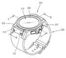
도 1은 본 발명의 일 실시예에 따르는 와치형 이동 단말기를 전면에서 바라본 사시도이다.1 is a perspective view of a watch-type mobile terminal according to an exemplary embodiment of the present invention.
상기 와치형 이동 단말기의 본체(110)는 손목에 착용 가능하도록 형성되는 밴드(120)와 연결된다. 상기 밴드(120)는 상기 본체(110)의 양측에 각각 연결된다.The
본체(110)은 무선통신 모듈(181, 도 10 참조)을 구비하여 이동통신 기지국과 무선 신호를 송/수신하도록 형성된다.The
상기 본체(110)의 외관은 프론트 케이스(111) 및 리어 케이스(112a, 도 2 참조)에 의하여 형성된다. 프론트 케이스(111) 및 리어 케이스(112)는 각종 전자부품이 내장되는 내부 공간을 형성한다.The outer appearance of the
단말기 본체, 주로 프론트 케이스(111)에는 디스플레이부(113), 음향 출력부(114), 영상 입력부(115) 또는 사용자 입력부(116, 117, 도 10 참조)가 배치될 수 있다.The
디스플레이부(113)는 프론트 케이스(111)의 주면의 대부분을 차지한다. 디스플레이부(113)는 디스플레이(113c, 도 3 참조)를 포함할 수 있다. 디스플레이(113c)는, 예를 들어 액정 디스플레이(liquid crystal display), 박막 트랜지스터 액정 디스플레이(thin film transistor-liquid crystal display), 유기 발광 다이오드(organic light-emitting diode), 플렉시블 디스플레이(flexible display), 3차원 디스플레이(3D display) 등이 될 수 있다. 디스플레이(113c)는 이를 통해 외부를 볼 수 있도록 투명하도록 구성될 수 있다. 이는 투명 디스플레이라 호칭될 수 있는데, 투명 디스플레이의 대표적인 예로는 TOLED(Transparent OLED) 등이 있다.The
와치형 이동 단말기의 구현 형태에 따라 디스플레이부(113)는 2개 이상 존재할 수도 있다. 디스플레이부(113)는 영상 정보와 시간 정보를 사용자의 정보 입력에 의하여 선택적으로 표시하도록 형성될 수 있다.There may be two or
디스플레이부(113)는 터치 센서(또는 터치 패드)를 더 포함하여 사용자의 터치에 의한 정보의 입력을 받을 수 있도록 형성될 수 있다. 터치 센서는 터치 입력 위치 및 면적 뿐만 아니라 터치 입력 압력까지도 검출할 수 있도록 구성될 수 있다. 터치 센서가 장착된 디스플레이부(113)는 터치 스크린을 형성한다.The
디스플레이부(113)의 양단부 중 일 단부에 인접한 영역에는 음향 출력부(114), 영상 입력부(115)가 배치된다.The
음향 출력부(114)는 음향을 출력할 수 있는 스피커 모듈과 같은 형태로 구현될 수 있다. 스피커 모듈은 리시버(Receiver) 또는 라우드 스피커(loud speaker)등을 포함할 수 있다.The
영상 입력부(115)는 사용자 등에 대한 이미지 또는 동영상을 촬영하기 위한 카메라 모듈(115c, 도 3 참조)과 같은 형태로 구현될 수 있다.The
디스플레이부(113)의 양단부 중 다른 단부에 인접한 영역에는 음향 입력부(187, 도 10 참조)가 배치될 수 있다. 음향 입력부(187)는 사용자의 음성, 기타 소리 등을 입력받기 위해, 예를 들어 마이크로폰과 같은 형태로 구현될 수 있다. 이러한 음향 입력부(187)는 단말기 본체의 측면에 배치되는 것도 가능하다.The sound input unit 187 (see FIG. 10) may be disposed in an area adjacent to the other end of both ends of the
사용자 입력부(116, 117)는 와치형 이동 단말기의 동작을 제어하기 위한 명령을 입력받기 위해 조작되는 장치를 말한다. 예를 들어, 사용자 입력부(116, 117)는 사용자의 푸시 또는 터치 조작에 의해 명령 또는 정보를 입력받을 수 있는 돔 스위치 또는 터치 스크린으로 구현되거나, 키를 회전시키는 휠 또는 조그 방식이나 조이스틱과 같이 조작하는 방식 등으로도 구현될 수 있다.The
터치 스크린은 출력 장치 이외에 제1 사용자 입력부(116)로 사용된다. 제2 사용자 입력부(117)는 프론트 케이스(111)의 측면에 배치될 수 있다.The touch screen is used as the
제1 또는 제2 사용자 입력부(116, 117)에 의하여 입력되는 내용은 다양하게 설정될 수 있다. 예를 들어, 제1 사용자 입력부(116)는 숫자 또는 문자, 심볼(symbol)과 같은 정보를 입력받도록 형성될 수 있다. 제2 사용자 입력부(117)는 시작이나 종료를 입력받거나, 음향 출력부(114)에서 출력되는 음향의 크기 조절 또는 디스플레이부(113)의 터치 인식 모드로의 전환 등과 같은 명령을 입력받도록 형성될 수 있다.The content input by the first or second
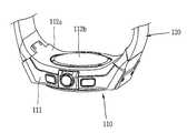
도 2는 도 1의 와치형 이동 단말기의 후면 사시도이다.2 is a rear perspective view of the watch-type mobile terminal of FIG.
리어 케이스(112a)는 상기 내부 공간을 한정하도록 프론트 케이스(111)와 결합한다. 덮개(112b)는 상기 내부 공간을 덮도록 리어 케이스(112a)에 장착된다.The
리어 케이스(112a) 및 덮개(112b)은 합성수지를 사출하여 형성되거나 금속 재질, 예를 들어 스테인레스 스틸(STS) 또는 티타늄(Ti) 등과 같은 금속 재질을 갖도록 형성될 수 있다.The
와치형 이동 단말기의 측면 또는 배면에는 인터페이스(188, 도 10 참조)가 배치될 수 있다.The interface 188 (see FIG. 10) may be disposed on the side or back of the watch-type mobile terminal.
인터페이스(188)는 와치형 이동 단말기가 외부 기기와 데이터 교환 등을 할 수 있게 하는 통로가 된다. 예를 들어, 인터페이스(188)는 유선 또는 무선으로, 이어폰과 연결하기 위한 접속단자, 근거리 통신을 위한 포트{예를 들어 적외선 포트(IrDA port), 블루투스 포트(Bluetooth port), 무선 랜 포트(wireless Lan port)등}, 또는 상기 와치형 이동 단말기에 전원을 공급하기 위한 전원공급 단자들 중 적어도 하나일 수 있다. 인터페이스(188)는 SIM(subscriber identification module) 또는 UIM(user identity module), 정보 저장을 위한 메모리 카드 등의 외장형 카드를 수용하는 카드 소켓일 수도 있다.The
인터페이스(188)의 일 예로, 리어 케이스(112a) 측에는 상기 와치형 이동 단말기의 적어도 일 구성요소에 전원을 공급하기 위하여, 외부 전원 공급 장치를 연결가능한 연결단자(미도시)가 형성될 수 있다. 연결단자(미도시)는 단말기의 전원공급부(190, 도 10 참조), 예를 들어 충전 가능한 배터리 등과 전기적으로 연결될 수 있다.As an example of the
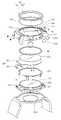
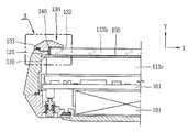
도 3은 도 1의 와치형 이동 단말기에 대한 분해도이고, 도 4는 도 1의 라인 Ⅳ-Ⅳ을 따라 취한 와치형 이동 단말기에 대한 단면도이다.FIG. 3 is an exploded view of the watch-type mobile terminal of FIG. 1, and FIG. 4 is a cross-sectional view of a watch-type mobile terminal taken along line IV-IV of FIG.
도 3을 참조하면, 프론트 케이스(111)의 전면에는 음향홀(114a) 및 영상홀(115a)이 형성되고, 프론트 케이스(111)의 내부에는 상기 음향홀(114a) 및 영상홀(115a)에 대응하도록 스피커 모듈(미도시) 및 카메라 모듈(115c)이 배치된다. 영상홀(115a)에는 광투과성으로 형성되는 영상윈도우(115b)가 장착될 수 있다. 이하, 외부를 향하는 상기 프론트 케이스(111)의 일면을 전면이라 칭하고, 내장 공간을 향하는 프론트 케이스(111)의 타면을 후면이라 정의한다. 음향홀(114a) 및 스피커 모듈은 음향 출력부(114)을 형성하고, 영상홀(115a) 및 카메라 모듈(115b)은 영상 입력부(115, 이상 도 1 참조)을 형성한다.3, an
상기 프론트 케이스(111)에는 제어 명령을 입력받도록 사용자가 누름 조작하는 대상이 되는 키패드(117b)가 장착된다. 구체적으로, 프론트 케이스(111)의 측면에는 상기 측면상에서 적어도 일부가 리세스되는 키패드 설치홈(117a)이 형성되고, 키패드 설치홈(117a)에는 키패드(117b)가 상기 키패드 설치홈(117a)의 측면을 따라 이동가능하도록 장착된다.The
프론트 케이스(111)의 전면에는 윈도우 홀(113a)이 형성되고, 지지부재(130)가 장착된다.A
지지부재(130)는 중공체로 이루어지며, 예를 들어 금속 재질로 형성되어, 와치형 이동 단말기의 데코레이션이 될 수 있다.The
지지부재(130)는 제1 및 제2 영역(131, 132)을 구비한다.The
제1 영역(131)은 상기 윈도우 홀(113a)을 감싸도록 형성되고, 제2 영역(132)은 상기 윈도우 홀(113a)의 가장자리를 가리도록 상기 제1 영역(131)에서 중공 부분을 향하여 연장된다. 일 예로, 제1 영역(131)은 환형으로 이루어지고, 프론트 케이스(111)의 전면을 덮도록 형성된다. 제2 영역(132)은 제1 영역(131)의 내주에서 중심으로 향하여 돌출되며, 윈도우 홀(113a)의 가장자리를 덮도록 형성된다.The
상기 프론트 케이스(111)의 전면과 지지부재(130) 사이에는 가스켓(133)이 배치될 수 있다. 가스켓(133)은 단말기 내부의 유체 유입을 제한하도록 지지부재(130)와 프론트 케이스(111)의 결합되는 부분을 실링시킨다.A
도시에 의하면, 윈도우(113b)가 윈도우홀(113a)에 대응하도록 배치된다.According to the drawing, the
윈도우(113b)는 빛이 투과할 수 있는 소재, 예를 들어 광투과성 합성수지, 강화 유리 등으로 구성된다. 다만 윈도우(113b)는 빛이 투과할 수 없는 부분을 포함할 수 있다. 이러한 부분은 빛이 투과할 수 없는 소재이거나 빛이 투과할 수 없도록 표면 처리된 영역이다.The
보다 구체적으로, 윈도우(113b)는 단말기 본체의 외부를 향하는 전면과 상기 전면과 반대되는 후면을 구비하고, 윈도우(113b) 전면의 적어도 일부가 상기 제2 영역(132)에 의하여 덮이도록 배치된다. 즉, 제2 영역(132)의 일면은 단말기의 내장공간을 바라보며, 윈도우(113b)는 전면이 상기 제2 영역(132)의 일면을 마주보도록 배치된다.More specifically, the
본 도면들을 참조하면, 윈도우홀(113a)과 윈도우(113b)의 사이에는 링 부재(140)가 끼워진다. 윈도우(113b)와 윈도우홀(113a)은 각각 원형으로 이루어질 수 있으며, 링 부재(140)는 윈도우(113b)가 고정되도록 상기 윈도우홀(113a)을 한정하는 면과 상기 윈도우(113b)의 외주면 사이에 끼워맞춤될 수 있다.Referring to these figures, a
윈도우(113b)의 후면에는 터치 패드(150)가 장착될 수 있다. 터치 패드(150)는 상기 윈도우(113b)의 후면을 덮도록 배치되며, 터치 입력을 감지하도록 형성된다.The
터치 패드(150)는 디스플레이부(113)의 특정 부위에 발생하는 정전용량, 전위경사 등의 변화를 전기적인 입력신호로 변환하도록 구성될 수 있다. 다만, 본 발명은 이에 한정되지 않으며, 예를 들어 터치 패드는 윈도우(113b)의 전면에 장착되어 디스플레이부(113)의 특정 부위에 가해진 압력을 검출할 수 있도록 형성될 수 있다.The
본 도면들을 참조하면, 터치 패드(150)는 전극막(151) 및 신호연결부재(152)를 포함한다.Referring to these drawings, the
전극막(151)은 터치 입력에 대응하는 전기 신호를 생성한다. 전극막(151)은, 터치를 감지하기 위하여 화면상의 좌표를 산출하는 수단으로서 사용되며, 예를 들어 ITO(Indium Tin Oxide) 전극막, CNT(Carbon nanotube) 전극막 등이 될 수 있다. 전극막(151)은 원형 또는 타원형으로 형성되고, 외주의 적어도 일부가 일 방향으로 돌출되도록 이루어진다.The
신호연결부재(152)는, 예를 들어 연성회로기판(Flexible Printed Circuit Board)가 될 수 있다. 신호연결부재(152)의 일단은 전극막(151)의 돌출되는 부분(151a)과 연결되며, 타단은 상기 전기 신호를 처리하도록 회로기판(161)과 연결된다.The
회로기판(161)은 지지 프레임(162)에 장착되며, 지지 프레임(162)은 상기 프론트 케이스(111)의 전면 및 측면에 의하여 한정되는 공간에 배치된다.The
지지 프레임(162)에는 적어도 하나의 전자부품이 결합될 수 있다. 지지 프레임(162)은 프론트 케이스(111)의 재질보다 높은 강도(剛度)나 높은 강성(强性)을 가지는 재질로 형성될 수 있다. 예를 들어, 프론트 케이스(111)가 합성수지, 예를 들어 폴리카보네이트 등으로 형성된다면, 지지 프레임(162)은 이보다 강도가 강한 스테인레스 스틸로 형성될 수 있다. 이를 통하여 지지 프레임(162)은 얇은 두께로 프론트 케이스(111)의 강도나 강성을 보강한다.At least one electronic component may be coupled to the
본 도면들을 참조하면, 지지 프레임(162)은 전면에서 디스플레이(113c)를 지지하고 후면에 배터리(191, 도 5 참조)가 삽입되도록 형성될 수 있다.Referring to these drawings, the
디스플레이(113c)는 원형 또는 타원형으로 이루어지며, 윈도우(113b) 및 지지부재(130)의 중공부분에 대응되게 배치된다. 이를 통하여 디스플레이(113c)에서 출력되는 시각 정보가 외부에서 인지될 수 있다. 윈도우(113b)는 디스플레이(113c)에 대응하는 면적을 가질 수 있다. 디스플레이(113c) 및 윈도우(113b)는 디스플레이부(113, 도 1 참조)를 구성할 수 있다.The
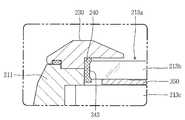
상기 프론트 케이스(111)의 후면에는 커버 부재(170)가 장착된다. 커버 부재(170)는 상기 윈도우(113b) 후면의 가장자리를 덮도록 형성되며, 중공체로 이루어진다. 커버 부재(170)는 링 부재(140)에 의하여 끼워맞춤되는 윈도우(113b)가 보다 견고하게 고정되도록 한다. 도시에 의하면, 상기 커버 부재(170)의 중공 부분은 상기 중공 부분의 중심축과 수직한 방향으로 적어도 일부가 개방된다.A
이하, 도 4 내지 도 7C를 참조하여 상기 윈도우의 장착 메커니즘에 대하여 보다 상세하게 설명한다. 도 5는 도 4의 A 부분의 확대도이고, 도 6은 도 1의 라인 Ⅵ-Ⅵ을 따라 취한 와치형 이동 단말기에 대한 단면도이며, 도 7A 내지 도 7C는 도 3의 와치형 이동 단말기가 조립되는 공정을 나타내는 공정도들이다.Hereinafter, the mounting mechanism of the window will be described in more detail with reference to Figs. 4 to 7C. FIG. 5 is an enlarged view of a portion A of FIG. 4, FIG. 6 is a cross-sectional view of the watch-type mobile terminal taken along the line VI-VI of FIG. 1, As shown in Fig.
도 5를 참조하면, 지지부재(130)의 제1 영역(131)은 제2 영역(132)에서 돌출되도록 이루어진다. 제1 및 제2 영역(131, 132)은 상기 제1 영역(131)의 돌출에 의하여 서로 단차를 형성하고, 상기 단차는 지지부재(130)의 중공부분이 윈도우(113b)의 전면에서 후면을 향하는 방향으로 순차적으로 넓어지도록 이루어진다. 이를 통하여, 윈도우(113b)의 조립시에, 윈도우(113b)는 프론트 케이스(111)의 후면에서 전면을 향하는 방향(+ Y 방향)으로 삽입될 수 있다. 이와 같이, 지지부재(130)는 + Y 방향으로 언더컷이 발생하지 않도록 이루어진다.Referring to FIG. 5, the
도시에 의하면, 링 부재(140)는 적어도 일부가 제2 영역(132)에 안착되도록 형성되며, 삽입된 윈도우(113b)는 링 부재(140)에 의하여 고정된다. 도 7A 내지 도 7C를 참조하여, 윈도우(113b)의 조립 공정을 설명한다.The
먼저, 도 7A와 같이 지지부재(130)의 제2 영역(132)에 링 부재(140)가 삽입되며, 이 때, 삽입 방향은 + Y 방향이 된다. 다음은, 도 7B와 같이 윈도우(113b)가 + Y 방향으로 삽입되며 윈도우 홀(113a)에서 링 부재(140)에 의하여 고정된다. 이 때에, 윈도우(113b)는 터치 패드(150)가 장착된 상태로 + Y 방향으로 삽입된다. 마지막으로 커버 부재(170)가 링 부재(140)와 윈도우(113b)의 후면을 덮도록 프론트 케이스(111)의 후면에 장착된다.First, as shown in FIG. 7A, the
상기 설명된 조립 공정은 바텀 업 방식(Bottom Up Type)의 조립 공정으로 탑 다운 방식(Top Down Type)에 비하여 윈도우의 베젤을 보다 좁게 형성할 수 있는 장점이 있다. 탑 다운 방식의 조립은 도 11에 도시된 종래의 윈도우(13b) 장착 구조에 적용된다.The assembling process described above is advantageous in that the bezel of the window can be formed narrower than the top down type in the bottom up type assembling process. Top-down assembly is applied to the
도 11은 종래의 방식으로 조립되는 단말기의 단면도이며, 도 11을 참조하면, 케이스(11)의 전면에서 윈도우 홀(13a)을 감싸는 부분은 내부 공간을 향하여 단차를 가지도록 이루어진다. 보다 구체적으로 케이스(11)의 전면에 대하여 리세스되는 단차부(14)가 형성되며, 단차부(14)에는 윈도우(13b)가 접착제(15) 또는 양면테이프를 매개로 장착되며, 이 때에 조립 방향은 - Y 방향이 된다. 도시한 바와 같이, 윈도우(13b)가 안착되기 위하여 단차부(14)는 충분한 넓이와 두께가 필요하며 따라서 윈도우 베젤은 보다 넓고 두껍게 구성된다. 또한 디스플레이(13c)와 윈도우(13b) 간의 간격(D)은 최소한 단차부(14)의 두께 이상이 된다.11 is a cross-sectional view of a terminal assembled in a conventional manner. Referring to FIG. 11, a portion of the front surface of the
이에 반해, 도 5를 참조하면, 본 발명의 윈도우 장착 메커니즘에 의하면, 커버 부재가 매우 얇은 판형으로 이루어질 수 있으므로, 디스플레이(113c)와 윈도우(113b) 간의 간격은 보다 가까워질 수 있다. 또한 이를 통하여, 디스플레이되는 화면이 윈도우상에서 보다 가깝게 형성되고, 화면의 밝기가 개선된다.On the other hand, referring to FIG. 5, according to the window mounting mechanism of the present invention, since the cover member can be formed in a very thin plate shape, the gap between the
도 5의 도시에 의하면, 링 부재(140)의 내주면에는 윈도우(113b)의 측면이 삽입되도록 삽입부(141)가 형성된다. 이에 더하여, 링 부재(140)의 내주면에는 윈도우(113b)의 삽입을 제한하도록 상기 삽입부(141)에서 지지부재(130)의 중공부분을 향하여 돌출되는 돌출부(142)가 형성될 수 있다. 예를 들어, 링 부재(140)의 단면은 + Y 방향으로 연장되다가 링 부재(140)의 중심을 향하여 절곡되도록 이루어질 수 있다. 이를 통하여 윈도우(113b)는 삽입부(141)를 따라 + Y 방향으로 삽입되며, 돌출부(142)에 도달함에 의하여 윈도후 홀(113a) 내의 특정 위치에서 고정된다.5, the
링 부재(140)는 윈도우(113b)의 측면이 삽입부(141)에 삽입되면, 윈도우 홀(113a)과 윈도우(113b)의 사이에서 탄성변형하도록 이루어진다. 보다 구체적으로, 링 부재(140)는 탄성재질로 이루어지고, 윈도우(113b)에 의하여 가압되어 압축변형한다. 이를 통하여, 링 부재(140)는 윈도우(113b)를 고정시킴과 동시에 방수를 위한 실링 역할을 하게 된다.The
도 6을 참조하면, 신호연결부재(152)는 전극막(151)의 외주에서 연장되어 회로기판(161)을 향하게 적어도 일부가 감기도록 배치된다. 보다 구체적으로, 윈도우(113b), 디스플레이(113c) 및 회로기판(161)은 적층되게 배치되며, 상기 신호연결부재(152)는 상기 전극막(151)의 외주에서 연장되고 상기 디스플레이(113c)를 지나 상기 회로기판(161)으로 연결된다.6, the
도시에 의하면, 단말기 바디는 적어도 일부가 상기 손목을 감는 방향으로 경사진 외관을 구비한다. 신호연결부재(152)는 경사진 부분의 내부 공간에서 감기게 된다.According to the present invention, the terminal body has an outer appearance at least partially inclined in a direction in which the wrist is wound. The
도 3을 참조하여 전술한 바와 같이, 커버 부재(170)의 중공 부분은 상기 중공 부분의 중심축과 수직한 방향으로 적어도 일부가 개방된다. 또한, 전극막(151)은 원형으로 형성되고, 외주의 적어도 일부가 커버 부재(170)의 개방되는 부분(171)을 향하여 돌출된다. 다시 도 6을 참조하면, 커버 부재(170)의 개방되는 부분(171)는 단말기 바디의 경사진 부분을 향하도록 배치된다.As described above with reference to Fig. 3, the hollow portion of the
신호연결부재(152)는 상기 커버 부재(170)의 개방되는 부분(171)을 관통하며, 신호연결부재(152)의 일단은 전극막(151)의 돌출되는 부분(151a)과 연결되며, 타단은 상기 전기 신호를 처리하도록 회로기판(161)과 연결된다. 만약, 도 11에 도시한 탑 다운 방식에 의하여 윈도우(13b)가 조립된다면 전극막과 회로기판 사이의 전기적 연결이 어려워질 것이나, 본 발명은 상기 설명과 같이 간단한 구조에 의하여 전기적 연결이 구현될 수 있다.The
도 8 및 도 9는 각각 본 발명과 관련한 와치형 이동 단말기의 다른 실시예를 나타내는 단면도들이다.8 and 9 are sectional views showing another embodiment of the watch mobile terminal according to the present invention, respectively.
도 8을 참조하면, 링 부재(240)의 내주면에는 윈도우(213b)의 측면이 삽입되도록 리세스부(243)가 형성된다. 리세스부는 링 부재(240)의 내주면에 수직한 방향으로 형성되며, 리세스부(243)의 바닥면(243a)에 윈도우(213b)의 측면이 안착된다.Referring to FIG. 8, a
상기 구조에 의하면, 윈도우는 링 부재의 탄성 변형에 의하여 끼워맞춤될 뿐만 아니라, 리세스부(243)에 삽입됨에 따라 고정될 수 있다. 따라서, 윈도우(113b)는 커버 부재(170, 도 5 참조)가 없어도 보다 견고히 고정될 수 있다.According to this structure, the window can be fixed not only by the elastic deformation of the ring member, but also by being inserted into the
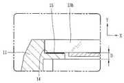
도 9를 참조하면, 지지부재(330)의 형상은 프론트 케이스(311)에 의하여 구현될 수 있다. 즉, 지지부재(330)는 단말기 바디의 일 케이스를 이루게 된다. 보다 구체적으로 프론트 케이스(311)는 윈도우 홀(313a)이 내부를 향하여 점차적으로 순차적으로 넓어지도록 형성된다.Referring to FIG. 9, the shape of the support member 330 may be realized by the
예를 들어, 윈도우 홀(313a)은 서로에 대해 높이차를 구비하는 제1 및 제2 단차면(311a, 311b)을 형성할 수 있다. 제1 및 제2 단차면(311a, 311b)은 각각 프론트 케이스(311)의 후면에 형성된다. 제1 단차면(311a)는 윈도우의 베젤(bezel)이 될 수 있으며, 제2 단차면(311b)에는 커버 부재(370)가 장착될 수 있다. 상기와 같은 구성에 의하여, 별도의 지지부재(130, 도 5 참조)가 없이 바텀-업 방식으로 조립되는 윈도우 장착 메커니즘이 구현될 수 있다.For example, the
도 10은 본 발명에 관련된 와치형 이동 단말기의 블록 구성도(block diagram)이다.10 is a block diagram of a watch-type mobile terminal according to the present invention.
도 10을 참조하면, 본 발명의 일 실시예에 따른 와치형 이동 단말기는 디스플레이부(113), 음향 출력부(114), 영상 입력부(115), 사용자 입력부(116, 117), 전원공급부(190), 제어부(180), 무선통신 모듈(181), 메모리(184), 방송수신 모듈(185), 센싱유닛(186), 음향 입력부(187), 인터페이스(188)를 포함한다.10, a watch type mobile terminal according to an exemplary embodiment of the present invention includes a
제어부(180)는 통상적으로 와치형 이동 단말기의 전반적인 동작을 제어한다. 예를 들어 음성 통화, 데이터 통신, 화상 통화 등을 위한 관련된 제어 및 처리를 수행한다.The
무선통신 모듈(181)은 안테나를 통하여 이동통신 기지국과 무선 신호를 송/수신한다. 예를 들어 제어부(180)의 제어 하에 음성 데이터, 문자 데이터, 영상 데이터 및 제어 데이터의 송수신을 담당하며 이를 위해 송신할 신호를 변조하여 송신하는 송신부(162)와, 수신되는 신호를 복조하는 수신부(183)을 포함한다.The
사용자 입력부(116, 117)는 사용자가 단말기의 동작 제어를 위하여 입력하는 키 입력 데이터를 제어부(180)에 제공한다. 사용자 입력부(116, 117)는 돔 스위치(dome switch), 터치 패드(정압/정전), 조그 휠, 조그 스위치 등으로 구성된다.The
영상 입력부(115)는 화상 통화모드 또는 촬영 모드에서 이미지 센서에 의해 얻어지는 정지영상 또는 동영상 등의 화상 프레임을 처리한다. 그리고, 처리된 화상 프레임은 디스플레이부(113)에 표시 가능한 영상 데이터로 변환되어 디스플레이부(113)로 출력된다.The
영상 입력부(115)에서 처리된 화상 프레임은 제어부(180)의 제어에 의해 메모리(184)에 저장되거나 무선통신 모듈(181)를 통하여 외부로 전송된다.The image frame processed by the
음향 입력부(187)는 통화모드 또는 녹음모드, 음성인식 모드 등에서 마이크로폰(Microphone)에 의해 외부의 음향 신호를 입력받아 전기적인 음성 데이터로 처리한다. 그리고, 처리된 음성 데이터는 통화 모드인 경우 무선통신 모듈(181)를 통하여 이동통신 기지국으로 송신 가능한 형태로 변환되어 무선통신 모듈(181)로 출력된다. 녹음 모드인 경우 처리된 음성 데이터는 메모리(184)에 저장되도록 출력된다.The
음향 입력부(187)는 외부의 음향 신호를 입력받는 과정에서 발생되는 잡음(noise)를 제거하기 위한 다양한 잡음 제거 알고리즘이 구현될 수 있다.The
디스플레이부(113)는 와치형 이동 단말기에서 처리되는 정보를 표시 출력한다. 예를 들어 와치형 이동 단말기가 통화 모드인 경우 제어부(180)의 제어에 의해 통화와 관련된 UI(User Interface) 또는 GUI(Graphic User Interface)를 표시 출력한다. 그리고 와치형 이동 단말기가 화상 통화 모드 또는 촬영 모드인 경우 제어부(180)의 제어에 의해 촬영된 영상 또는 UI,GUI를 표시 출력한다. 디스플레이부(113)는 터치 스크린을 포함하여 구성되는 경우, 출력 장치 이외에 입력 장치로 사용된다.The
음향 출력부(114)는 호신호 수신, 통화모드 또는 녹음 모드, 음성인식 모드, 방송수신 모드 등에서 제어부(180)의 제어에 의해 무선통신 모듈(181)로부터 수신된 음향 데이터 또는 메모리(184)에 저장된 음향 데이터를 변환하여 외부로 출력한다.The
또한, 음향 출력부(114)는 와치형 이동 단말기에서 수행되는 기능(예를 들어, 호신호 수신음, 메시지 수신음 등)과 관련된 음향 신호를 출력한다.Also, the
센싱유닛(186)은 와치형 이동 단말기의 개폐 상태, 와치형 이동 단말기의 위치, 사용자 접촉 유무 등과 같이 와치형 이동 단말기의 현 상태를 감지하여 와치형 이동 단말기의 동작을 제어하기 위한 센싱 신호를 발생시킨다. 예를 들어 와치형 이동 단말기가 슬라이드 폰 형태인 경우 슬라이드 폰의 개폐 여부를 센싱하여 제어부(180)로 센싱 결과를 출력하여 단말기의 동작이 제어되도록 한다. 또한 전원 공급부(190)의 전원 공급 여부, 인터 페이스(188)의 외부 기기 결합 여부 등과 관련된 센싱 기능을 담당한다.The
인터페이스(188)는 와치형 이동 단말기 이외 유/무선 헤드셋, 외부 충전기, 유/무선 데이터 포트, 카드 소켓(예를 들어, 메모리 카드(Memory card), SIM/UIM card) 등을 와치형 이동 단말기에 연결되는 모든 외부기기와의 인터페이스 역할을 한다. 이와 같은 인터페이스(188)는 외부 기기로부터 데이터를 전송받거나 전원을 공급받아 와치형 이동 단말기 내부의 각 구성 요소에 전달하거나 와치형 이동 단말기 내부의 데이터가 외부 기기로 전송되도록 한다.The
메모리(184)는 제어부(180)의 처리 및 제어를 위한 프로그램이 저장될 수도 있고, 입/출력되는 데이터들(예를 들어, 폰북, 메시지, 정지영상, 동영상 등)의 임시 저장을 위한 기능을 수행할 수도 있다.The
또한, 메모리(184)에는 본 발명과 관련된 와치형 이동 단말기의 동작을 제어하는 프로그램이 저장된다A program for controlling the operation of the watch-type mobile terminal related to the present invention is stored in the
이러한 메모리(184)는 일반적으로 알려진 하드 디스크, 카드 타입의 메모리(예를 들어 SD 또는 XD 메모리 등), 플래시 메모리, 램, 롬 등의 개념을 포함한다.
방송수신 모듈(185)은 위성 또는 지상파 등을 통하여 전송된 방송 신호를 수신하여 음향 출력부(114), 디스플레이부(113)에 출력 가능한 방송 데이터 형태로 변환하여 제어부(180)에 출력한다. 또한 방송수신 모듈(185)은 방송과 관련된 부가 데이터(예를 들면, EPG(Electric Program Guide), 채널 리스트 등)를 수신한다. 방송수신 모듈(185)에서 변환된 방송 데이터 및 부가 데이터는 메모리(184)에 저장될 수도 있다.The
전원 공급부(190)는 제어부(180)의 제어에 의해 외부의 전원, 내부의 전원을 인가받아 각 구성요소들의 동작에 필요한 전원을 공급한다.The
상기와 같은 와치형 이동 단말기는 위에서 설명된 실시예들의 구성과 방법에 한정되는 것이 아니라, 상기 실시예들은 다양한 변형이 이루어질 수 있도록 각 실시예들의 전부 또는 일부가 선택적으로 조합되어 구성될 수도 있다.
The above-described watch mobile terminal is not limited to the configuration and method of the embodiments described above, but all or some of the embodiments may be selectively combined so that various modifications may be made to the embodiments.
Claims (17)
Translated fromKorean중공체로 이루어지며, 상기 윈도우 홀을 감싸도록 형성되는 제1 영역과 상기 윈도우 홀의 가장자리를 가리도록 상기 제1 영역에서 중공 부분을 향하여 연장되는 제2 영역을 구비하는 지지부재;
상기 본체의 외부를 향하는 전면과 상기 전면과 반대되는 후면을 구비하고, 상기 윈도우 홀에서 상기 전면의 적어도 일부가 상기 제2 영역에 의하여 덮이도록 배치되는 윈도우; 및
상기 윈도우가 고정되도록 상기 윈도우 홀과 상기 윈도우의 사이에 끼워지는 링 부재를 포함하고,
상기 링 부재의 내주면에는 상기 윈도우의 측면이 삽입되도록 리세스부가 형성되며, 상기 링 부재의 상측 및 하측은 상기 윈도우를 향하여 돌출되어 상기 리세스부의 바닥면에 상기 윈도우의 측면이 안착되는 와치형 이동 단말기A body in which a window hole is formed;
A support member made of a hollow body and having a first region formed to surround the window hole and a second region extended from the first region toward the hollow portion so as to cover the edge of the window hole;
A window having a front surface facing the outside of the main body and a rear surface opposite to the front surface, the window being arranged such that at least a part of the front surface of the window hole is covered by the second area; And
And a ring member sandwiched between the window hole and the window so that the window is fixed,
Wherein a recess portion is formed on an inner circumferential surface of the ring member so as to insert a side surface of the window, and upper and lower sides of the ring member protrude toward the window, and a side surface of the window is seated on a bottom surface of the recess portion terminal
상기 지지부재는 상기 본체의 일면에 장착되며, 상기 제1 영역은 상기 본체의 일면을 덮도록 형성되는 것을 특징으로 하는 와치형 이동 단말기.The method according to claim 1,
Wherein the support member is mounted on one surface of the main body, and the first region is formed to cover one surface of the main body.
상기 링 부재는 적어도 일부가 상기 제2 영역에 안착되도록 형성되는 것을 특징으로 하는 와치형 이동 단말기.The method according to claim 1,
Wherein the ring member is formed such that at least a part thereof is seated in the second region.
상기 제1 및 제2 영역은 상기 제1 영역의 돌출에 의하여 서로 단차를 형성하고,
상기 단차는 상기 지지부재의 중공부분이 상기 윈도우의 전면에서 후면을 향하는 방향으로 순차적으로 넓어지도록 이루어지는 것을 특징으로 하는 와치형 이동 단말기.The method according to claim 1,
Wherein the first and second regions form steps with projections of the first region,
Wherein the stepped portion is formed so that the hollow portion of the support member is sequentially widened in a direction from the front surface to the rear surface of the window.
상기 윈도우의 후면을 덮도록 배치되며, 터치 입력을 감지하도록 형성되는 터치 패드를 더 포함하며,
상기 터치 패드는,
상기 터치 입력에 대응하는 전기 신호를 생성하며, 외주의 적어도 일부가 일 방향으로 돌출되는 전극막; 및
일단은 상기 전극막의 돌출되는 부분과 연결되며, 타단은 상기 전기 신호를 처리하도록 회로기판과 연결되는 신호연결부재를 포함하는 와치형 이동 단말기.The method according to claim 1,
And a touch pad disposed to cover the rear surface of the window and configured to sense a touch input,
The touch pad includes:
An electrode film which generates an electric signal corresponding to the touch input and at least a part of the outer periphery protrudes in one direction; And
And a signal connection member connected to the protruding portion of the electrode film at one end and connected to the circuit board to process the electrical signal at the other end.
상기 신호연결부재는 상기 전극막의 외주에서 연장되어 상기 회로기판을 향하도록 적어도 일부가 감기는 것을 특징으로 하는 와치형 이동 단말기.10. The method of claim 9,
Wherein the signal connection member extends from an outer periphery of the electrode film and is at least partially wound toward the circuit board.
상기 중공부분에 대응하도록 배치되는 디스플레이를 더 포함하고,
상기 윈도우, 디스플레이 및 회로기판은 적층되게 배치되며, 상기 신호연결부재는 상기 전극막의 외주에서 연장되고 상기 디스플레이를 지나 상기 회로기판으로 연결되는 것을 특징으로 하는 와치형 이동 단말기.12. The method of claim 11,
And a display disposed to correspond to the hollow portion,
Wherein the window, the display, and the circuit board are stacked, and the signal connection member extends from an outer periphery of the electrode film and is connected to the circuit board through the display.
상기 본체에 장착되며, 상기 윈도우 후면의 가장자리를 덮도록 형성되는 커버 부재를 더 포함하는 와치형 이동 단말기.The method according to claim 1,
And a cover member mounted on the main body and formed to cover an edge of the rear surface of the window.
상기 커버 부재는 중공체로 이루어지고,
상기 커버 부재의 중공 부분은 상기 중공 부분의 중심축과 수직한 방향으로 적어도 일부가 개방되는 것을 특징으로 하는 와치형 이동 단말기.14. The method of claim 13,
Wherein the cover member is made of a hollow body,
Wherein the hollow portion of the cover member is at least partially opened in a direction perpendicular to the center axis of the hollow portion.
상기 윈도우는 원형으로 이루어지고, 상기 윈도우의 후면에는 터치 패드가 배치되며,
상기 터치 패드는,
원형으로 형성되고, 외주의 적어도 일부가 상기 커버 부재의 개방되는 부분을 향하여 돌출되는 전극막; 및
상기 커버 부재의 개방되는 부분을 관통하도록 배치되고, 일단은 상기 전극막의 돌출되는 부분과 연결되며, 타단은 전기 신호를 처리하도록 회로기판과 연결되는 신호연결부재를 포함하는 와치형 이동 단말기.15. The method of claim 14,
Wherein the window is formed in a circular shape, a touch pad is disposed on a rear surface of the window,
The touch pad includes:
An electrode film which is formed in a circular shape and in which at least a part of an outer periphery protrudes toward an open portion of the cover member; And
And a signal connection member which is arranged to penetrate the open portion of the cover member and has one end connected to the protruding portion of the electrode film and the other end connected to the circuit board to process an electric signal.
상기 본체 내부의 유체 유입을 제한하도록 상기 본체의 일면과 상기 지지부재 사이에 배치되는 가스켓을 더 포함하는 와치형 이동 단말기.The method according to claim 1,
And a gasket disposed between one side of the main body and the support member to restrict fluid inflow into the main body.
상기 지지부재는 상기 본체의 일 케이스를 이루는 것을 특징으로 하는 와치형 이동 단말기.
The method according to claim 1,
Wherein the support member comprises a case of the main body.
Priority Applications (4)
| Application Number | Priority Date | Filing Date | Title |
|---|---|---|---|
| KR1020100022981AKR101659023B1 (en) | 2010-03-15 | 2010-03-15 | Watch type mobile terminal |
| US12/956,994US8773847B2 (en) | 2010-03-15 | 2010-11-30 | Watch type mobile terminal |
| EP10194337.1AEP2367292B1 (en) | 2010-03-15 | 2010-12-09 | Watch type mobile terminal |
| CN201010623063.4ACN102196072B (en) | 2010-03-15 | 2010-12-31 | Watch Type Mobile Terminal |
Applications Claiming Priority (1)
| Application Number | Priority Date | Filing Date | Title |
|---|---|---|---|
| KR1020100022981AKR101659023B1 (en) | 2010-03-15 | 2010-03-15 | Watch type mobile terminal |
Publications (2)
| Publication Number | Publication Date |
|---|---|
| KR20110103761A KR20110103761A (en) | 2011-09-21 |
| KR101659023B1true KR101659023B1 (en) | 2016-09-23 |
Family
ID=44116941
Family Applications (1)
| Application Number | Title | Priority Date | Filing Date |
|---|---|---|---|
| KR1020100022981AExpired - Fee RelatedKR101659023B1 (en) | 2010-03-15 | 2010-03-15 | Watch type mobile terminal |
Country Status (4)
| Country | Link |
|---|---|
| US (1) | US8773847B2 (en) |
| EP (1) | EP2367292B1 (en) |
| KR (1) | KR101659023B1 (en) |
| CN (1) | CN102196072B (en) |
Families Citing this family (120)
| Publication number | Priority date | Publication date | Assignee | Title |
|---|---|---|---|---|
| US8497884B2 (en) | 2009-07-20 | 2013-07-30 | Motorola Mobility Llc | Electronic device and method for manipulating graphic user interface elements |
| US8355297B2 (en)* | 2009-11-05 | 2013-01-15 | Devon Works, LLC | Watch assembly having a plurality of time-coordinated belts |
| KR20130032195A (en)* | 2011-09-22 | 2013-04-01 | 엘지전자 주식회사 | Mobile device |
| EP2801079A1 (en)* | 2012-01-06 | 2014-11-12 | Koninklijke Philips N.V. | Emergency response and tracking using lighting networks |
| AU2013302897A1 (en)* | 2012-08-13 | 2015-03-05 | Aliphcom | Component protective overmolding using protective external coatings |
| US9081542B2 (en)* | 2012-08-28 | 2015-07-14 | Google Technology Holdings LLC | Systems and methods for a wearable touch-sensitive device |
| AU346480S (en)* | 2012-09-20 | 2013-01-21 | Swarovski Ag | Watchcase for wristwatches |
| US11237719B2 (en) | 2012-11-20 | 2022-02-01 | Samsung Electronics Company, Ltd. | Controlling remote electronic device with wearable electronic device |
| US11372536B2 (en) | 2012-11-20 | 2022-06-28 | Samsung Electronics Company, Ltd. | Transition and interaction model for wearable electronic device |
| US11157436B2 (en) | 2012-11-20 | 2021-10-26 | Samsung Electronics Company, Ltd. | Services associated with wearable electronic device |
| US10551928B2 (en) | 2012-11-20 | 2020-02-04 | Samsung Electronics Company, Ltd. | GUI transitions on wearable electronic device |
| US9030446B2 (en)* | 2012-11-20 | 2015-05-12 | Samsung Electronics Co., Ltd. | Placement of optical sensor on wearable electronic device |
| US8994827B2 (en) | 2012-11-20 | 2015-03-31 | Samsung Electronics Co., Ltd | Wearable electronic device |
| US9477313B2 (en) | 2012-11-20 | 2016-10-25 | Samsung Electronics Co., Ltd. | User gesture input to wearable electronic device involving outward-facing sensor of device |
| US10185416B2 (en) | 2012-11-20 | 2019-01-22 | Samsung Electronics Co., Ltd. | User gesture input to wearable electronic device involving movement of device |
| US10423214B2 (en) | 2012-11-20 | 2019-09-24 | Samsung Electronics Company, Ltd | Delegating processing from wearable electronic device |
| JP5708631B2 (en)* | 2012-12-13 | 2015-04-30 | カシオ計算機株式会社 | Content distribution system, content processing server device, and content distribution method |
| TWI562556B (en)* | 2012-12-26 | 2016-12-11 | Hon Hai Prec Ind Co Ltd | Portable electronic device having nfc antenna |
| CN103970004A (en)* | 2013-01-29 | 2014-08-06 | 联想(北京)有限公司 | Wrist-worn type electronic device and control method |
| CN103970291B (en)* | 2013-01-31 | 2018-08-14 | 索尼公司 | Mobile terminal |
| US9753436B2 (en) | 2013-06-11 | 2017-09-05 | Apple Inc. | Rotary input mechanism for an electronic device |
| EP2813907B1 (en)* | 2013-06-11 | 2018-08-01 | LG Electronics, Inc. | Watch type mobile terminal |
| JP1515093S (en)* | 2013-07-26 | 2017-12-25 | ||
| JP1515092S (en)* | 2013-07-26 | 2017-12-25 | ||
| USD717760S1 (en)* | 2013-07-26 | 2014-11-18 | Lg Electronics Inc. | Mobile phone |
| USD731455S1 (en)* | 2013-07-26 | 2015-06-09 | Lg Electronics Inc. | Mobile phone |
| JP1515094S (en)* | 2013-07-26 | 2017-12-25 | ||
| JP1515102S (en)* | 2013-08-05 | 2017-12-25 | ||
| EP3014400B1 (en) | 2013-08-09 | 2020-06-03 | Apple Inc. | Tactile switch for an electronic device |
| CN103472708A (en)* | 2013-09-18 | 2013-12-25 | 苏州朗昇通信科技有限公司 | Combined intelligent watch |
| US9643349B2 (en) | 2013-09-27 | 2017-05-09 | Apple Inc. | Insert molded splits in housings |
| USD725073S1 (en)* | 2013-12-02 | 2015-03-24 | Lg Electronics Inc. | Mobile phone |
| USD719125S1 (en)* | 2013-12-02 | 2014-12-09 | Lg Electronics Inc. | Mobile phone |
| KR102216879B1 (en)* | 2014-01-14 | 2021-02-19 | 삼성디스플레이 주식회사 | Mounting device for mounting flexible printed circuit board and method for mounting thereof |
| KR102194822B1 (en)* | 2014-01-16 | 2020-12-24 | 삼성디스플레이 주식회사 | Display apparatus reducing dead space |
| KR102114319B1 (en)* | 2014-01-22 | 2020-05-25 | 삼성디스플레이 주식회사 | Display apparatus |
| US10048802B2 (en) | 2014-02-12 | 2018-08-14 | Apple Inc. | Rejection of false turns of rotary inputs for electronic devices |
| JP1526348S (en)* | 2014-02-19 | 2018-06-04 | ||
| US10691332B2 (en) | 2014-02-28 | 2020-06-23 | Samsung Electronics Company, Ltd. | Text input on an interactive display |
| CN104898406B (en)* | 2014-03-07 | 2017-11-07 | 联想(北京)有限公司 | Electronic device and acquisition control method |
| USD746815S1 (en)* | 2014-03-31 | 2016-01-05 | Lg Electronics Inc. | Mobile phone |
| USD746816S1 (en)* | 2014-03-31 | 2016-01-05 | Lg Electronics Inc. | Mobile phone |
| US20150286391A1 (en)* | 2014-04-08 | 2015-10-08 | Olio Devices, Inc. | System and method for smart watch navigation |
| JP2015207034A (en)* | 2014-04-17 | 2015-11-19 | アルパイン株式会社 | information input device and information input method |
| US20150346877A1 (en)* | 2014-05-30 | 2015-12-03 | Microsoft Corporation | Wearable electronic device |
| US9442518B2 (en)* | 2014-06-02 | 2016-09-13 | Microsoft Technology Licensing, Llc | Mounting wedge for flexible material |
| KR102309289B1 (en)* | 2014-06-11 | 2021-10-06 | 엘지전자 주식회사 | Watch type mobile terminal |
| KR102350063B1 (en)* | 2014-07-01 | 2022-01-11 | 삼성전자주식회사 | Wearable type electronic device |
| KR20250021617A (en) | 2014-09-02 | 2025-02-13 | 애플 인크. | Wearable electronic device |
| US9785123B2 (en)* | 2014-09-26 | 2017-10-10 | Intel Corporation | Digital analog display with rotating bezel |
| KR102263982B1 (en)* | 2014-10-20 | 2021-06-11 | 엘지디스플레이 주식회사 | Display apparatus |
| CN104507277A (en)* | 2014-11-28 | 2015-04-08 | 深圳富泰宏精密工业有限公司 | Wearable type electronic device |
| JP6187776B2 (en)* | 2014-12-12 | 2017-08-30 | カシオ計算機株式会社 | Electronics |
| KR102315671B1 (en)* | 2015-01-19 | 2021-10-21 | 삼성디스플레이 주식회사 | Display device |
| US9678588B2 (en) | 2015-01-28 | 2017-06-13 | Sony Corporation | Wire-bonded borderless display |
| KR102329820B1 (en)* | 2015-01-29 | 2021-11-23 | 삼성전자주식회사 | Wearable type device |
| MY181524A (en)* | 2015-02-27 | 2020-12-25 | Samsung Electronics Co Ltd | Electronic device |
| KR102313898B1 (en)* | 2015-02-27 | 2021-10-19 | 삼성전자주식회사 | Wearable electronic device |
| KR20160105268A (en)* | 2015-02-27 | 2016-09-06 | 삼성전자주식회사 | Electronic device |
| EP3251139B1 (en) | 2015-03-08 | 2021-04-28 | Apple Inc. | Compressible seal for rotatable and translatable input mechanisms |
| KR101637368B1 (en)* | 2015-03-10 | 2016-07-07 | 엘지전자 주식회사 | Watch type mobile terminal |
| US10067583B2 (en) | 2015-03-31 | 2018-09-04 | Sony Corporation | Virtual borderless display |
| US10222755B2 (en)* | 2015-04-21 | 2019-03-05 | Motorola Mobility Llc | Device with axial lock and retention device and methods therefor |
| CH711037A1 (en) | 2015-05-05 | 2016-11-15 | Swissgear Sarl | Mobile phone in the form of a watch. |
| CN104991672B (en)* | 2015-07-06 | 2018-06-05 | 业成光电(深圳)有限公司 | Touching device and electronic device |
| US9507325B1 (en) | 2015-07-16 | 2016-11-29 | Ifthikhar Ismail Barrie | Wearable mobile device system |
| KR102448688B1 (en)* | 2015-08-13 | 2022-09-29 | 삼성전자주식회사 | Electronic device comprising a rotatable structure |
| TWI583292B (en)* | 2015-09-03 | 2017-05-11 | 宏碁股份有限公司 | Electronic device and assembly method thereof |
| US10148000B2 (en) | 2015-09-04 | 2018-12-04 | Apple Inc. | Coupling structures for electronic device housings |
| US9907191B2 (en) | 2015-09-30 | 2018-02-27 | Apple Inc. | Multi-part electronic device housing having contiguous filled surface |
| USD812051S1 (en)* | 2015-11-09 | 2018-03-06 | Lg Electronics Inc. | Portable wrist wearable device |
| WO2017088164A1 (en)* | 2015-11-27 | 2017-06-01 | 华为技术有限公司 | Antenna of wearable device and wearable device |
| TWI581080B (en)* | 2016-01-12 | 2017-05-01 | 巨擘科技股份有限公司 | Smart wristwatch structure |
| US10551798B1 (en) | 2016-05-17 | 2020-02-04 | Apple Inc. | Rotatable crown for an electronic device |
| US10372166B2 (en) | 2016-07-15 | 2019-08-06 | Apple Inc. | Coupling structures for electronic device housings |
| US10061399B2 (en) | 2016-07-15 | 2018-08-28 | Apple Inc. | Capacitive gap sensor ring for an input device |
| US10019097B2 (en) | 2016-07-25 | 2018-07-10 | Apple Inc. | Force-detecting input structure |
| USD819627S1 (en)* | 2016-11-11 | 2018-06-05 | Matrix Industries, Inc. | Thermoelectric smartwatch |
| KR102806816B1 (en)* | 2016-11-23 | 2025-05-16 | 삼성전자주식회사 | Wearable-type electronic device with finger print scan sensor |
| EP4257034A1 (en)* | 2017-01-13 | 2023-10-11 | Huawei Technologies Co., Ltd. | Wearable device |
| JP6562277B2 (en)* | 2017-04-10 | 2019-08-21 | カシオ計算機株式会社 | Case and watch |
| KR102355149B1 (en)* | 2017-04-25 | 2022-01-25 | 삼성전자주식회사 | Electronic device comprising detachable input device |
| TWI645688B (en)* | 2017-07-11 | 2018-12-21 | 巨擘科技股份有限公司 | Wearable device and method of operation thereof |
| US10962935B1 (en) | 2017-07-18 | 2021-03-30 | Apple Inc. | Tri-axis force sensor |
| KR102395783B1 (en) | 2017-08-04 | 2022-05-09 | 삼성전자주식회사 | Wearable device and electronic device |
| KR102420019B1 (en)* | 2017-08-07 | 2022-07-12 | 삼성전자주식회사 | Wearable device and electronic device |
| KR102534712B1 (en)* | 2017-11-30 | 2023-05-22 | 삼성전자주식회사 | Wearable electronic device having a fingerprint sensor |
| CN112074229A (en)* | 2018-03-02 | 2020-12-11 | 日东电工株式会社 | Wearable Physiological Devices and Devices |
| US11360440B2 (en) | 2018-06-25 | 2022-06-14 | Apple Inc. | Crown for an electronic watch |
| US11561515B2 (en) | 2018-08-02 | 2023-01-24 | Apple Inc. | Crown for an electronic watch |
| US12259690B2 (en) | 2018-08-24 | 2025-03-25 | Apple Inc. | Watch crown having a conductive surface |
| CN211293787U (en) | 2018-08-24 | 2020-08-18 | 苹果公司 | Electronic watch |
| CN209625187U (en) | 2018-08-30 | 2019-11-12 | 苹果公司 | Electronic Watches and Electronic Devices |
| CN109413605A (en)* | 2018-10-24 | 2019-03-01 | 东莞理工学院 | Wearable medical wireless communication inductor |
| US10849246B2 (en)* | 2018-12-21 | 2020-11-24 | Apple Inc. | Device enclosure |
| US10474194B1 (en)* | 2019-01-30 | 2019-11-12 | Garmin Switzerland Gmbh | Wearable electronic device with an inductive user interface |
| US11194299B1 (en) | 2019-02-12 | 2021-12-07 | Apple Inc. | Variable frictional feedback device for a digital crown of an electronic watch |
| JP6913306B2 (en)* | 2019-04-01 | 2021-08-04 | カシオ計算機株式会社 | Exterior parts, cases and watches |
| US10575425B1 (en)* | 2019-06-11 | 2020-02-25 | Shenzhen Xiwxi Technology Co., Ltd | Waterproof housing for wearable device |
| KR102848437B1 (en) | 2019-07-31 | 2025-08-21 | 삼성전자주식회사 | Electronic device having electrode measuring biological signal |
| US11838432B2 (en) | 2019-12-03 | 2023-12-05 | Apple Inc. | Handheld electronic device |
| US11553608B2 (en)* | 2019-12-20 | 2023-01-10 | Samsung Electronics Co., Ltd. | Wearable electronic device including ventilation and waterproof structure |
| US11550268B2 (en) | 2020-06-02 | 2023-01-10 | Apple Inc. | Switch module for electronic crown assembly |
| US12174660B2 (en) | 2020-06-11 | 2024-12-24 | Apple Inc. | Electronic device |
| US11573599B2 (en) | 2020-06-11 | 2023-02-07 | Apple Inc. | Electrical connectors for electronic devices |
| CN111743272A (en)* | 2020-07-13 | 2020-10-09 | 中国人民解放军北部战区总医院 | A new type of smart sports bracelet for health management |
| KR20230024388A (en) | 2020-07-15 | 2023-02-20 | 삼성전자주식회사 | Small data transmission method and apparatus |
| KR102864611B1 (en)* | 2020-07-22 | 2025-09-25 | 삼성전자 주식회사 | Electronic device and electrode in the same |
| US11800649B2 (en)* | 2020-08-19 | 2023-10-24 | Apple Inc. | Mobile display encapsulation to improve robustness and water resistance |
| US11889647B2 (en) | 2020-08-19 | 2024-01-30 | Apple Inc. | Display panel bend reinforcement |
| JP7146180B2 (en)* | 2020-08-20 | 2022-10-04 | カシオ計算機株式会社 | case and watch |
| US11784673B2 (en) | 2020-09-16 | 2023-10-10 | Apple Inc. | Electronic device housing having a radio-frequency transmissive component |
| US12092996B2 (en) | 2021-07-16 | 2024-09-17 | Apple Inc. | Laser-based rotation sensor for a crown of an electronic watch |
| US12396686B2 (en) | 2021-08-31 | 2025-08-26 | Apple Inc. | Sensing health parameters in wearable devices |
| US11769940B2 (en) | 2021-09-09 | 2023-09-26 | Apple Inc. | Electronic device housing with integrated antenna |
| US12388168B2 (en) | 2021-09-23 | 2025-08-12 | Apple Inc. | Portable electronic device having integrated antenna elements |
| EP4407387A4 (en) | 2022-03-25 | 2025-03-05 | Samsung Electronics Co., Ltd. | ELECTRONIC DEVICE WITH DISPLAY |
| US20230375981A1 (en)* | 2022-05-02 | 2023-11-23 | Derek Jose Galindo Sedgwick | Solar energy charging watch and electronic key device and operating system thereof |
| US12189347B2 (en) | 2022-06-14 | 2025-01-07 | Apple Inc. | Rotation sensor for a crown of an electronic watch |
| EP4557265A4 (en)* | 2022-09-16 | 2025-07-09 | Honor Device Co Ltd | ELECTRONIC DEVICE |
Family Cites Families (27)
| Publication number | Priority date | Publication date | Assignee | Title |
|---|---|---|---|---|
| US2699034A (en)* | 1951-05-02 | 1955-01-11 | Tavannes Watch Co Sa | Steering wheel wound clock for motor vehicles |
| GB1479779A (en)* | 1973-09-25 | 1977-07-13 | Citizen Watch Co Ltd | Liquid crystal display wrist watch |
| JPS5749880A (en)* | 1980-09-09 | 1982-03-24 | Seiko Epson Corp | Glass part structure for portable clock |
| US5033035A (en)* | 1989-09-27 | 1991-07-16 | Mondaine Watch Ltd. | Watertight watch |
| JPH0623133U (en)* | 1991-09-27 | 1994-03-25 | カシオ計算機株式会社 | Panel switch device |
| CH688364B5 (en)* | 1994-11-04 | 1998-02-27 | Ebauchesfabrik Eta Ag | Timepiece comprising a sealed container mounted in a box "you metal. |
| JP3523043B2 (en)* | 1998-01-20 | 2004-04-26 | 株式会社エヌ・ティ・ティ・ドコモ | Wristwatch-type communication device and its antenna |
| JP3975627B2 (en)* | 1998-12-31 | 2007-09-12 | カシオ計算機株式会社 | Data communication device |
| KR20010043047A (en)* | 1999-02-26 | 2001-05-25 | 하루타 히로시 | Wristwatch case |
| JP3753933B2 (en)* | 2000-08-18 | 2006-03-08 | セイコーインスツル株式会社 | Watches |
| EP1416343A1 (en)* | 2002-10-28 | 2004-05-06 | ETA SA Manufacture Horlogère Suisse | Push button control, in particular for time piece, and portable electronic instrument comprising such a button |
| JP2005098975A (en)* | 2003-09-01 | 2005-04-14 | Casio Comput Co Ltd | Watch case |
| CN2672696Y (en) | 2003-12-19 | 2005-01-19 | 深圳市兴标龙表业有限公司 | Wrist watch shell |
| FR2869120B1 (en) | 2004-04-15 | 2006-08-25 | World Wide Watch | INTERACTIVE WATCH. |
| US7793361B2 (en)* | 2004-11-12 | 2010-09-14 | Nike, Inc. | Article of apparel incorporating a separable electronic device |
| JP2007024582A (en)* | 2005-07-13 | 2007-02-01 | Agilent Technol Inc | Display panel inspection device and interface used therefor |
| WO2008007783A1 (en)* | 2006-07-13 | 2008-01-17 | Citizen Holdings Co., Ltd. | Clock with wireless function |
| TW200913653A (en) | 2007-09-12 | 2009-03-16 | da-peng Zheng | Watch-type body-temperature-charged interruption-free mobile phone device |
| BRPI0804270A2 (en)* | 2007-11-05 | 2009-07-14 | Lg Electronics Inc | mobile terminal |
| KR101427266B1 (en)* | 2007-12-20 | 2014-08-06 | 엘지전자 주식회사 | Mobile terminal |
| KR101427260B1 (en) | 2007-11-05 | 2014-08-06 | 엘지전자 주식회사 | Band type portable terminal |
| US8009521B2 (en)* | 2008-08-13 | 2011-08-30 | Kun-Chi Wu | Wristwatch with concave glass lens and dial |
| KR101587092B1 (en)* | 2008-11-04 | 2016-01-20 | 엘지전자 주식회사 | Mobile terminal |
| KR101529921B1 (en)* | 2008-11-04 | 2015-06-18 | 엘지전자 주식회사 | Watch type terminal |
| JP5685582B2 (en)* | 2009-04-26 | 2015-03-18 | ナイキ イノベイト セー. フェー. | Exercise clock |
| KR101595384B1 (en)* | 2009-07-20 | 2016-02-18 | 엘지전자 주식회사 | Watch type mobile terminal |
| KR101587138B1 (en)* | 2009-08-27 | 2016-02-02 | 엘지전자 주식회사 | Mobile terminal |
- 2010
- 2010-03-15KRKR1020100022981Apatent/KR101659023B1/ennot_activeExpired - Fee Related
- 2010-11-30USUS12/956,994patent/US8773847B2/ennot_activeExpired - Fee Related
- 2010-12-09EPEP10194337.1Apatent/EP2367292B1/ennot_activeNot-in-force
- 2010-12-31CNCN201010623063.4Apatent/CN102196072B/ennot_activeExpired - Fee Related
Also Published As
| Publication number | Publication date |
|---|---|
| US8773847B2 (en) | 2014-07-08 |
| EP2367292B1 (en) | 2016-05-18 |
| EP2367292A2 (en) | 2011-09-21 |
| CN102196072A (en) | 2011-09-21 |
| EP2367292A3 (en) | 2012-03-14 |
| KR20110103761A (en) | 2011-09-21 |
| US20110221688A1 (en) | 2011-09-15 |
| CN102196072B (en) | 2014-03-05 |
Similar Documents
| Publication | Publication Date | Title |
|---|---|---|
| KR101659023B1 (en) | Watch type mobile terminal | |
| KR101587138B1 (en) | Mobile terminal | |
| US7920904B2 (en) | Mobile terminal | |
| KR101437991B1 (en) | Mobile terminal | |
| KR102468709B1 (en) | Key module and mobile terminal having the same, and method for assembling the key module | |
| KR101604704B1 (en) | Watch type mobile terminal | |
| KR20180049916A (en) | Mobile terminal | |
| US7852618B2 (en) | Function extending assembly and portable terminal having the same | |
| KR101659020B1 (en) | Portable terminal | |
| KR20160126453A (en) | Key apparatus and mobile terminal having the same | |
| US10804047B2 (en) | Mobile terminal | |
| KR101441922B1 (en) | A touch sensor assembly and a portable terminal having the touch sensor assembly | |
| KR101622636B1 (en) | Watch type mobile terminal | |
| KR101502008B1 (en) | Portable terminal | |
| KR101622678B1 (en) | Mobile terminal | |
| KR101604801B1 (en) | Portable terminal | |
| KR101604749B1 (en) | Portable terminal and manufacturing method of portable terminal case | |
| KR20200019412A (en) | Mobile terminal | |
| KR101604701B1 (en) | Portable terminal | |
| KR101495180B1 (en) | Display assembly and portable terminal having the same | |
| KR101504213B1 (en) | Switch assembley and portable terminal having the same | |
| KR101587136B1 (en) | Mobile terminal | |
| KR101677627B1 (en) | Mobile terminal | |
| KR101635033B1 (en) | Mobile terminal | |
| KR101595362B1 (en) | Portable terminal |
Legal Events
| Date | Code | Title | Description |
|---|---|---|---|
| PA0109 | Patent application | St.27 status event code:A-0-1-A10-A12-nap-PA0109 | |
| PG1501 | Laying open of application | St.27 status event code:A-1-1-Q10-Q12-nap-PG1501 | |
| A201 | Request for examination | ||
| E13-X000 | Pre-grant limitation requested | St.27 status event code:A-2-3-E10-E13-lim-X000 | |
| P11-X000 | Amendment of application requested | St.27 status event code:A-2-2-P10-P11-nap-X000 | |
| P13-X000 | Application amended | St.27 status event code:A-2-2-P10-P13-nap-X000 | |
| PA0201 | Request for examination | St.27 status event code:A-1-2-D10-D11-exm-PA0201 | |
| PN2301 | Change of applicant | St.27 status event code:A-3-3-R10-R13-asn-PN2301 St.27 status event code:A-3-3-R10-R11-asn-PN2301 | |
| D13-X000 | Search requested | St.27 status event code:A-1-2-D10-D13-srh-X000 | |
| D14-X000 | Search report completed | St.27 status event code:A-1-2-D10-D14-srh-X000 | |
| E902 | Notification of reason for refusal | ||
| PE0902 | Notice of grounds for rejection | St.27 status event code:A-1-2-D10-D21-exm-PE0902 | |
| E13-X000 | Pre-grant limitation requested | St.27 status event code:A-2-3-E10-E13-lim-X000 | |
| P11-X000 | Amendment of application requested | St.27 status event code:A-2-2-P10-P11-nap-X000 | |
| P13-X000 | Application amended | St.27 status event code:A-2-2-P10-P13-nap-X000 | |
| P22-X000 | Classification modified | St.27 status event code:A-2-2-P10-P22-nap-X000 | |
| E701 | Decision to grant or registration of patent right | ||
| PE0701 | Decision of registration | St.27 status event code:A-1-2-D10-D22-exm-PE0701 | |
| PR0701 | Registration of establishment | St.27 status event code:A-2-4-F10-F11-exm-PR0701 | |
| PR1002 | Payment of registration fee | St.27 status event code:A-2-2-U10-U11-oth-PR1002 Fee payment year number:1 | |
| PG1601 | Publication of registration | St.27 status event code:A-4-4-Q10-Q13-nap-PG1601 | |
| PR1001 | Payment of annual fee | St.27 status event code:A-4-4-U10-U11-oth-PR1001 Fee payment year number:4 | |
| PN2301 | Change of applicant | St.27 status event code:A-5-5-R10-R13-asn-PN2301 St.27 status event code:A-5-5-R10-R11-asn-PN2301 | |
| PR1001 | Payment of annual fee | St.27 status event code:A-4-4-U10-U11-oth-PR1001 Fee payment year number:5 | |
| PC1903 | Unpaid annual fee | St.27 status event code:A-4-4-U10-U13-oth-PC1903 Not in force date:20210914 Payment event data comment text:Termination Category : DEFAULT_OF_REGISTRATION_FEE | |
| PC1903 | Unpaid annual fee | St.27 status event code:N-4-6-H10-H13-oth-PC1903 Ip right cessation event data comment text:Termination Category : DEFAULT_OF_REGISTRATION_FEE Not in force date:20210914 |