KR101656723B1 - Feedthrough making method - Google Patents
Feedthrough making methodDownload PDFInfo
- Publication number
- KR101656723B1 KR101656723B1KR1020150092754AKR20150092754AKR101656723B1KR 101656723 B1KR101656723 B1KR 101656723B1KR 1020150092754 AKR1020150092754 AKR 1020150092754AKR 20150092754 AKR20150092754 AKR 20150092754AKR 101656723 B1KR101656723 B1KR 101656723B1
- Authority
- KR
- South Korea
- Prior art keywords
- ceramic structure
- platinum
- iridium
- feedthrough
- ceramic
- Prior art date
- Legal status (The legal status is an assumption and is not a legal conclusion. Google has not performed a legal analysis and makes no representation as to the accuracy of the status listed.)
- Expired - Fee Related
Links
Images


Classifications
- A—HUMAN NECESSITIES
- A61—MEDICAL OR VETERINARY SCIENCE; HYGIENE
- A61N—ELECTROTHERAPY; MAGNETOTHERAPY; RADIATION THERAPY; ULTRASOUND THERAPY
- A61N1/00—Electrotherapy; Circuits therefor
- A61N1/18—Applying electric currents by contact electrodes
- A61N1/32—Applying electric currents by contact electrodes alternating or intermittent currents
- A61N1/36—Applying electric currents by contact electrodes alternating or intermittent currents for stimulation
- A61N1/372—Arrangements in connection with the implantation of stimulators
- A61N1/375—Constructional arrangements, e.g. casings
- A61N1/3752—Details of casing-lead connections
- A61N1/3754—Feedthroughs
- A—HUMAN NECESSITIES
- A61—MEDICAL OR VETERINARY SCIENCE; HYGIENE
- A61N—ELECTROTHERAPY; MAGNETOTHERAPY; RADIATION THERAPY; ULTRASOUND THERAPY
- A61N1/00—Electrotherapy; Circuits therefor
- A61N1/18—Applying electric currents by contact electrodes
- A61N1/32—Applying electric currents by contact electrodes alternating or intermittent currents
- A61N1/36—Applying electric currents by contact electrodes alternating or intermittent currents for stimulation
- A61N1/372—Arrangements in connection with the implantation of stimulators
- A61N1/375—Constructional arrangements, e.g. casings
- B—PERFORMING OPERATIONS; TRANSPORTING
- B23—MACHINE TOOLS; METAL-WORKING NOT OTHERWISE PROVIDED FOR
- B23K—SOLDERING OR UNSOLDERING; WELDING; CLADDING OR PLATING BY SOLDERING OR WELDING; CUTTING BY APPLYING HEAT LOCALLY, e.g. FLAME CUTTING; WORKING BY LASER BEAM
- B23K20/00—Non-electric welding by applying impact or other pressure, with or without the application of heat, e.g. cladding or plating
- B23K20/02—Non-electric welding by applying impact or other pressure, with or without the application of heat, e.g. cladding or plating by means of a press ; Diffusion bonding
- B—PERFORMING OPERATIONS; TRANSPORTING
- B23—MACHINE TOOLS; METAL-WORKING NOT OTHERWISE PROVIDED FOR
- B23K—SOLDERING OR UNSOLDERING; WELDING; CLADDING OR PLATING BY SOLDERING OR WELDING; CUTTING BY APPLYING HEAT LOCALLY, e.g. FLAME CUTTING; WORKING BY LASER BEAM
- B23K26/00—Working by laser beam, e.g. welding, cutting or boring
- B23K26/36—Removing material
- B23K26/38—Removing material by boring or cutting
- H—ELECTRICITY
- H01—ELECTRIC ELEMENTS
- H01G—CAPACITORS; CAPACITORS, RECTIFIERS, DETECTORS, SWITCHING DEVICES, LIGHT-SENSITIVE OR TEMPERATURE-SENSITIVE DEVICES OF THE ELECTROLYTIC TYPE
- H01G4/00—Fixed capacitors; Processes of their manufacture
- H01G4/35—Feed-through capacitors or anti-noise capacitors
- H—ELECTRICITY
- H01—ELECTRIC ELEMENTS
- H01R—ELECTRICALLY-CONDUCTIVE CONNECTIONS; STRUCTURAL ASSOCIATIONS OF A PLURALITY OF MUTUALLY-INSULATED ELECTRICAL CONNECTING ELEMENTS; COUPLING DEVICES; CURRENT COLLECTORS
- H01R2201/00—Connectors or connections adapted for particular applications
- H01R2201/12—Connectors or connections adapted for particular applications for medicine and surgery
Landscapes
- Engineering & Computer Science (AREA)
- Health & Medical Sciences (AREA)
- Power Engineering (AREA)
- Life Sciences & Earth Sciences (AREA)
- General Health & Medical Sciences (AREA)
- Biomedical Technology (AREA)
- Nuclear Medicine, Radiotherapy & Molecular Imaging (AREA)
- Radiology & Medical Imaging (AREA)
- Veterinary Medicine (AREA)
- Animal Behavior & Ethology (AREA)
- Public Health (AREA)
- Mechanical Engineering (AREA)
- Microelectronics & Electronic Packaging (AREA)
- Manufacturing & Machinery (AREA)
- Physics & Mathematics (AREA)
- Optics & Photonics (AREA)
- Plasma & Fusion (AREA)
- Laser Beam Processing (AREA)
- Ceramic Products (AREA)
Abstract
Translated fromKoreanDescription
Translated fromKorean본 발명은 피드스루 제조방법에 관한 것으로, 특히 뇌심부자극기, 이식형 제세동기, 이식형 척수자극기 등과 같은 인체 이식형 의료기기에 사용 가능한 기밀성을 가지도록 하는 피드스루를 제조하기 위한 피드스루 제조방법에 관한 것이다.
The present invention relates to a feed-through manufacturing method and more particularly to a feedthrough manufacturing method for manufacturing a feedthrough having airtightness usable in a human implantable medical device such as a deep brain stimulator, implantable defibrillator, implantable spinal cord stimulator, .
현재 Pacemaker, Implantable Cardio-vertor Defibrillator (ICD), Deep Brain Stimulator (DBS), Spinal Stimulation System 등과 같은 다양한 인체 이식형 의료기기들이 판매되고 있다.Various human implantable medical devices such as Pacemaker, Implantable Cardio-vertigo Defibrillator (ICD), Deep Brain Stimulator (DBS) and Spinal Stimulation System are sold.
이들 의료기기들의 기밀성 패키지는 생체적합성이 확보되어야 하기 때문에 티타늄으로 제작된다. 또한 티타늄 패키지 내부에 있는 전기자극회로와 외부의 자극용 전극 사이를 연결하기 위해 피드스루를 필요로 한다. 이러한 피드스루는 주로 티타늄 플랜지(Flange), 세라믹 구조체 및 백금/이리듐 핀의 접합에 의해 제작되며, 브레이징과 메탈라이징, 밀폐성 실링(Hermetic Sealing) 기술의 복합적인 접합을 통하여 제작된다.The confidentiality package of these medical devices is made of titanium because biocompatibility must be ensured. It also requires feedthrough to connect the electrical stimulation circuitry inside the titanium package to the external stimulation electrode. These feedthroughs are fabricated primarily by the bonding of titanium flanges, ceramic structures and platinum / iridium fins, and are made through a combination of brazing and metallizing and Hermetic Sealing techniques.
그러나 활성 금속인 티타늄은 쉽게 산화되는 성질을 가지며, 이러한 산화는 브레이징의 강도를 급격히 낮추기 때문에 브레이징의 신뢰성을 확보하기가 쉽지 않고 브레이징 과정을 매우 까다롭고 복잡하게 만든다. 예를 들어, 티타늄의 산화막을 제거하고 플럭스를 도포하고 접합로의 가스 분위기를 정밀하게 조절하여 브레이징 과정에서 티타늄의 산화를 방지하는 과정이 필요하며, 몰리망간(MoMn)을 주성분으로 하는 페이스트(Paste)를 사용하여 세라믹의 표면을 메탈라이징 공정 및 메탈라이징 된 세라믹에 니켈(Ni)을 도금하는 공정 등을 필요로 한다.However, titanium, which is an active metal, has the property of being easily oxidized and this oxidation is not easy to secure the reliability of the brazing because the strength of the brazing is drastically lowered, making the brazing process very complicated and complicated. For example, it is necessary to remove the oxide film of titanium and apply a flux to precisely adjust the gas atmosphere of the joint furnace to prevent the oxidation of titanium in the brazing process. In addition, a paste containing molybdenum (MoMn) ) Is required to process the surface of the ceramic by a metalizing process and a process of plating nickel (Ni) on the metallized ceramic.
이러한 다단계 브레이징 공정은 전 공정이 인체에 무해한 원료만을 이용하여 이루어져야하기 때문에 티타늄의 산화를 막기 위한 플럭스와 티타늄-세라믹 사이를 접합하는데 쓰이는 용가재의 선택에 있어서 제약이 따르며, 세라믹의 메탈라이징에 필요한 몰리망간(MoMn)을 주성분으로 하는 페이스트(Paste)에 첨가되는 소량의 불순물이 인체에 미치는 영향이 고려되어야 한다.This multi-step brazing process is limited to the selection of the flux used to prevent the oxidation of titanium and the titanium-ceramics, since the entire process must be performed using only raw materials harmless to the human body. The molybdenum required for metalizing ceramics The influence of a small amount of impurities added to a paste containing manganese (MoMn) as a main component on the human body should be considered.
또한 세라믹 구조체와 백금/이리듐 핀의 접합을 위해서는 세라믹 구조체의 표면을 메탈라이징 하여야 하는데, 백금/이리듐 핀을 끼워넣는 세라믹 구조체 내의 홀 사이즈가 매우 작아 메탈라이징이 쉽지 않다.Also, in order to bond the ceramic structure to the platinum / iridium pin, the surface of the ceramic structure must be metallized. However, since the hole size in the ceramic structure that sandwiches the platinum / iridium pin is very small, metalization is not easy.
기존의 세라믹 메탈라이제이션과 브레이징을 통해 피드스루를 제작하는 방법에 대해서 다시 한번 정리하면 하기와 같은 문제점이 있다.There is a problem as follows when the conventional method of manufacturing the feedthrough through the ceramic metallization and the brazing is summarized again.
첫째, 활성 금속인 티타늄이 브레이징 과정에서 쉽게 산화되기 때문에 브레이징된 피드스루의 기밀성에 있어서의 재현성이 낮다는 문제점이 있다.First, there is a problem that the reproducibility of the airtightness of the brazed feed-through is low because titanium, which is an active metal, is easily oxidized during the brazing process.
둘째, 브레이징에 의해 기밀성을 확보하기 위해서 티타늄의 산화막을 제거하고 플럭스를 도포하고 접합로의 가스 분위기를 정밀하게 조절하여야 하는 등 공정과정이 매우 복잡하다는 문제점이 있다.Secondly, there is a problem that the process is complicated, for example, to remove the titanium oxide film and to apply flux and precisely control the gas atmosphere in the junction furnace in order to ensure airtightness by brazing.
셋째, 세라믹과 금속의 접합부에 몰리망간(MoMn)을 주성분으로 하는 페이스트(Paste)를 사용하여 메탈라이징을 행해야 하며 메탈라이징 된 세라믹에 니켈(Ni)을 도금하는 공정을 필요로 하는데, 백극/이리듐 핀이 삽입되는 세라믹 상의 홀의 지름이 너무 작아 메탈라이징 및 도금 공정을 수행하기가 용이하지 않다는 문제점이 있다.Third, metalization must be performed using a paste containing molybdenum (MoMn) as a main component at the junction of the ceramic and the metal, and a step of plating nickel (Ni) on the metallized ceramic is required. There is a problem in that it is not easy to carry out the metalizing and plating process because the diameter of the hole in the ceramic body into which the pin is inserted is too small.
넷째, 인체 이식형 의료기기는 생체적합성을 확보하여야 하기 때문에 브레이징 공정에서 티타늄의 산화를 막기 위해 사용되는 플럭스와 브레이징을 위해 사용되는 용가재의 선택에 있어 제약이 따른다는 문제점이 있다.Fourth, since human implantable medical devices must secure biocompatibility, there is a problem in selection of fluxes used for preventing oxidation of titanium in brazing process and for use of brazing materials.
다섯째, 네일헤드를 갖는 피드스루 핀을 사용하여 확산접합을 통해 기밀성을 갖는 피드스루를 제작하는 방법은 단조나 주조를 통해 네일헤드를 만드는 것이 용이하지 않아 생산성이 매우 낮다는 문제점이 있다.
Fifth, there is a problem in that the productivity of the nail head is low due to the difficulty in making the nail head through forging or casting by the method of manufacturing the feedthrough having airtightness through the diffusion bonding using the feedthrough pin having the nail head.
이와 같은 문제점을 해소시키기 위해 본 발명은 이식형 제세동기, 이식형 척수자극기 등과 같은 인체 이식형 의료기기에 사용 가능한 기밀성을 가지도록 하는 피드스루를 제조하기 위한 피드스루 제조방법을 제공하는데, 그 목적이 있다.In order to solve such a problem, the present invention provides a method of manufacturing a feedthrough for manufacturing a feedthrough having an airtightness usable in a human implantable medical device such as an implantable defibrillator, a transplantable spinal cord stimulator, etc., .
또한, 본 발명은 확산접합을 이용한 이중접합 방식에 의해 피드스루 본체를 형성시키고, 피드스루 본체에 레이저 홀 가공 방식을 적용시켜 피드스루 본체에 핀홀을 형성시키고 모세관 현상을 통해 핀을 형성시킬 수 있는 피드스루 제조방법을 제공하는데, 그 목적이 있다.The present invention also provides a method of forming a feedthrough body by a double bonding method using diffusion bonding and applying a laser hole processing method to the feedthrough body to form a pinhole in the feedthrough body and form a pin through capillary phenomenon Feed through method.
또한, 본 발명은 확산접합시 접합공정 과정에서 자연적으로 산화막에 제거되기 때문에 사전에 산화막을 제거하거나 접합공정 중에 티타늄이 산화되는 것을 방지하기 위해 플럭스를 사용하거나 가스 분위기를 정밀하게 조절해줄 필요가 없는 피드스루 제조방법을 제공하는데, 그 목적이 있다.Further, since the present invention is naturally removed in the oxide film during the diffusion bonding process, it is unnecessary to use the flux or precisely adjust the gas atmosphere in order to remove the oxide film in advance or prevent the titanium from being oxidized during the bonding process Feed through method.
또한, 본 발명은 확산접하시 플럭스나 용가제와 같은 추가적인 물질을 사용할 필요가 없으며, 이종 물질을 원자력이 작용하는 범위까지 근접시켜 확산에 의해 접합이 이루어지므로 세라믹을 메탈라이징 시킬 필요가 없도록 하는 피드스루 제조방법을 제공하는데, 그 목적이 있다.In addition, the present invention does not require the use of additional materials such as fluxes or fillers during diffusion contact, and the dissimilar materials are brought close to the range in which the atomic force acts and are joined by diffusion. Therefore, a feed that eliminates the need to metallize the ceramic Through fabrication method.
또한, 본 발명은 레이저 홀가공시 모세관 현상에 의해 피드스루 형상이 형성되므로, 사전에 네일헤드를 갖는 피드스루 형상을 가공할 필요가 없도록 하는 피드스루 제조방법을 제공하는데, 그 목적이 있다.It is another object of the present invention to provide a feedthrough manufacturing method that eliminates the need to previously process a feedthrough shape having a nail head because the laser hole is formed by the feedthrough shape by the capillary phenomenon of the present invention.
또한, 본 발명은 피드스루와 세라믹의 홀 사이에 간격이 존재하지 않도록 하는 피드스루 제조방법을 제공하는데, 그 목적이 있다.
The present invention also provides a method of manufacturing a feedthrough in which there is no gap between the feedthrough and the hole of the ceramic.
본 발명의 실시예에 따른 피드스루 제조방법은 내부에 안착홈이 형성된 하부 지그의 상기 안착홈에 복수개의 홈들이 등간격으로 형성된 세라믹 구조체를 안착시키는 단계; 세라믹 구조체의 복수개의 홈들에 백금 및 이리듐 합금으로 이루어진 백금-이리듐 핀을 인입시키는 단계; 세라믹 구조체 상부에 티타늄으로 이루어진 티타늄 플랜지를 적층시켜, 세라믹 구조체, 백금-이리듐 핀 및 티타늄 플랜지로 이루어진 피드스루 구조물을 형성시키는 단계; 저면에 홈부가 형성된 상부 지그의 홈부에 피드스루 구조물 상단면을 위치시킨 후 가압하여 상부 지그가 하부지그의 안착홈에 끼워져 결합된 후 확산접합 공정챔버로 이송시키고, 피드스루 구조물의 세라믹 구조체, 백금-이리듐 핀 및 티타늄 플랜지가 확산접합공정에 따라 상호 접합되는 단계; 확산접합공정 수행 후 확산접합 공정챔버 내부의 온도를 낮추어 상호 접합된 피드스루 구조물을 식히는 단계; 식힌 피드스루 구조물의 세라믹 구조체가 레이저 가공수단에 대향되도록 위치시키는 단계; 백금/이리듐 핀이 인입된 세라믹 구조체 위치로 레이저를 방사시키고, 레이저 방사에 따라 세라믹 구조체 상에 홀이 형성시키는 단계; 및 세라믹 구조체 상에 형성된 홀을 따라 세라믹 구조체 상부로 백금-이리듐 핀의 용융물이 이동되어 세라믹 구조체 상부에 백금/이리듐 핀의 일부를 노출시키는 단계를 포함할 수 있다.
A method of manufacturing a feedthrough according to an embodiment of the present invention includes: placing a ceramic structure having a plurality of grooves formed at equal intervals in the seating groove of a lower jig having a seating groove formed therein; Introducing a platinum-iridium pin made of platinum and iridium alloy into a plurality of grooves of the ceramic structure; Depositing a titanium flange made of titanium on the ceramic structure to form a feedthrough structure comprising a ceramic structure, a platinum-iridium pin, and a titanium flange; The upper end surface of the feed-through structure is positioned in the groove portion of the upper jig where the groove portion is formed on the bottom surface of the lower jig, and then the upper jig is inserted into the seating groove of the lower sheet and then transferred to the diffusion bonding process chamber. The iridium pin and the titanium flange being mutually bonded according to a diffusion bonding process; Cooling the interconnected feedthrough structure by reducing the temperature inside the diffusion bonding process chamber after performing the diffusion bonding process; Positioning the ceramic structure of the cooled feedthrough structure so as to face the laser processing means; Emitting a laser to a position of the ceramic structure into which the platinum / iridium pin is introduced, and forming holes on the ceramic structure according to the laser emission; And exposing a portion of the platinum / iridium pin to the top of the ceramic structure by moving the platinum-iridium fin melt onto the ceramic structure along the holes formed on the ceramic structure.
본 발명과 관련된 실시예로서, 백금/이리듐 핀의 끝단부와 티타늄 플랜지의 끝단부가 일직선상에 위치할 수 있다.
As an embodiment related to the present invention, the end of the platinum / iridium pin and the end of the titanium flange may be positioned in a straight line.
본 발명과 관련된 실시예로서, 상부 지그 및 하부 지그가 세라믹으로 이루어지는 것이 바람직하다.
As an embodiment related to the present invention, it is preferable that the upper jig and the lower jig are made of ceramic.
본 발명과 관련된 실시예로서, 상부 지그가 하부 지그 상부에 끼워진 상태로 결합될 때 세라믹 구조체의 일부가 상부 지그 외부로 노출될 수 있다.
According to the embodiment of the present invention, when the upper jig is engaged with the upper portion of the lower jig, a part of the ceramic structure may be exposed to the outside of the upper jig.
본 발명과 관련된 실시예로서, 상기 세라믹 구조체는, 백금과 이리듐이 용융되어 세라믹 구조체의 외면으로 흘러 유동되는 것을 방지하기 위해 다수 개가 세라믹 구조체에 음각형성되는 유동방지홈이 더 포함될 수 있다.
As an embodiment related to the present invention, the ceramic structure may further include a flow preventing groove formed in a plurality of ceramic structures to prevent platinum and iridium from melting and flowing to the outer surface of the ceramic structure.
본 발명은 세라믹 메탈라이제이션과 브레이징을 통해 피드스루를 제작하는 방법과 비교하여 확산접합과 레이저 홀가공을 통해 기밀성에 있어 보다 높은 재현성과 생산성을 확보할 수 있도록 하는 효과가 있다.The present invention has the effect of securing higher reproducibility and productivity in airtightness through diffusion bonding and laser hole processing as compared with a method of manufacturing feedthrough through ceramic metallization and brazing.
또한, 본 발명은 확산접합을 이용한 이종접합은 플럭스와 용가재 등 추가적인 물질을 필요로 하지 않으며, 금속의 산화 상태에서 접합을 수행하기 때문에 티타늄의 산화에 의한 접합 강도의 약화를 걱정할 필요가 없어 재현성 및 생체적합성을 확보할 수 있도록 하는 효과가 있다.In addition, the present invention does not require additional materials such as flux and filler material, and does not need to worry about weakening the bonding strength due to oxidation of titanium because the bonding is performed in the oxidation state of the metal, It is possible to secure biocompatibility.
또한 본 발명은 확산접합시 세라믹의 메탈라이징이나 니켈(Ni) 도금 등등의 다단계 공정을 필요로 하지 않기 때문에 전체 접합 공정이 간단하며, 다단계 공정에 의한 불순물의 유입을 최소화할 수 있도록 하는 효과가 있다.In addition, since the present invention does not require a multistage process such as metallization of ceramic or nickel (Ni) plating at the time of diffusion bonding, the entire bonding process is simple and has the effect of minimizing the inflow of impurities by a multistage process .
또한 본 발명은 두 이종 물질 간의 계면에서 확산이 이루어지기 때문에 접합 강도가 매우 세며 기계적 충격에 강한 효과가 있다.Further, since the diffusion occurs at the interface between two dissimilar materials, the present invention has a very high bonding strength and a strong effect on mechanical shock.
또한, 본 발명에 따른 레이저 홀가공을 이용한 피드스루 형상을 구현하는 방식은 단조 및 주조에 의한 피드스루의 제작 방법에 비해 제작이 용이하고 생산성이 높다는 효과가 있으며. 특히 백금/이리듐의 주조가 어려운 국내 현실을 생각할 때, 재료에 제한을 받지 않는다는 효과가 있다.In addition, the method of implementing the feed-through shape using the laser hole machining according to the present invention has the effect of being easy to manufacture and high productivity as compared with the feed through method by forging and casting. In particular, when considering the domestic reality that platinum / iridium casting is difficult, there is an effect that the material is not limited.
또한, 본 발명은 레이저 홀가공을 이용하면 모세관 현상에 통해 피드스루를 형성하기 때문에 세라믹 바디와 백금/이리듐 핀 간의 간극이 존재하지 않는다는 효과가 있으며, 또한 레이저 스팟 사이즈를 조절하여 다양한 지름을 갖는 피드스루 핀의 제작이 가능하도록 하는 효과가 있다. 이는 정해진 크기의 피드스루에 더 많은 채널 수를 구현하는데 용이하도록 한다.
In addition, since the feedthrough is formed through the capillary phenomenon by using the laser hole processing, the present invention has an effect that there is no gap between the ceramic body and the platinum / iridium pin, and the laser spot size is adjusted, Thereby making it possible to manufacture a through-fin. This facilitates the implementation of a larger number of channels in a given size feedthrough.
도 1은 본 발명에 따라 제작된 피드스루를 설명하기 위한 도면이다.
도 2는 본 발명에 따른 피드스루 제작방법을 설명하기 위한 공정도이다.
도 3은 본 발명에 따른 확산접합을 위해 상하부 지그에 피드스루가 결합된 상태를 설명하기 위한 도면이다.
도 4는 본 발명에 따른 확산접합공정 후 레이저 홀 가공 공정을 설명하기 위한 도면이다.
도 5는 도 4의 레이저 홀 가공 후 모세관 현상에 따라 백금/이리듐이 홀을 따라 상승하여 핀이 형성되는 공정을 설명하기 위한 도면이다.1 is a view for explaining a feedthrough manufactured according to the present invention.
2 is a process diagram for explaining a method of manufacturing a feedthrough according to the present invention.
3 is a view for explaining a state in which the feedthrough is coupled to upper and lower jigs for diffusion bonding according to the present invention.
4 is a view for explaining a laser hole forming process after the diffusion bonding process according to the present invention.
FIG. 5 is a view for explaining a process in which platinum / iridium rises along a hole according to a capillary phenomenon after laser hole processing in FIG. 4 to form a fin.
본 발명에서 사용되는 기술적 용어는 단지 특정한 실시 예를 설명하기 위해 사용된 것으로, 본 발명을 한정하려는 의도가 아님을 유의해야 한다. 또한, 본 발명에서 사용되는 기술적 용어는 본 발명에서 특별히 다른 의미로 정의되지 않는 한, 본 발명이 속하는 기술 분야에서 통상의 지식을 가진 자에 의해 일반적으로 이해되는 의미로 해석되어야 하며, 과도하게 포괄적인 의미로 해석되거나, 과도하게 축소된 의미로 해석되지 않아야 한다. 또한, 본 발명에서 사용되는 기술적인 용어가 본 발명의 사상을 정확하게 표현하지 못하는 잘못된 기술적 용어일 때에는, 당업자가 올바르게 이해할 수 있는 기술적 용어로 대체되어 이해되어야 할 것이다. 또한, 본 발명에서 사용되는 일반적인 용어는 사전에 정의되어 있는 바에 따라, 또는 전후 문맥상에 따라 해석되어야 하며, 과도하게 축소된 의미로 해석되지 않아야 한다.It is noted that the technical terms used in the present invention are used only to describe specific embodiments and are not intended to limit the present invention. In addition, the technical terms used in the present invention should be construed in a sense generally understood by a person having ordinary skill in the art to which the present invention belongs, unless otherwise defined in the present invention, Should not be construed to mean, or be interpreted in an excessively reduced sense. In addition, when a technical term used in the present invention is an erroneous technical term that does not accurately express the concept of the present invention, it should be understood that technical terms can be understood by those skilled in the art. In addition, the general terms used in the present invention should be interpreted according to a predefined or prior context, and should not be construed as being excessively reduced.
또한, 본 발명에서 사용되는 단수의 표현은 문맥상 명백하게 다르게 뜻하지 않는 한 복수의 표현을 포함한다. 본 발명에서, "구성된다" 또는 "포함한다" 등의 용어는 발명에 기재된 여러 구성 요소들, 또는 여러 단계를 반드시 모두 포함하는 것으로 해석되지 않아야 하며, 그 중 일부 구성 요소들 또는 일부 단계들은 포함되지 않을 수도 있고, 또는 추가적인 구성 요소 또는 단계들을 더 포함할 수 있는 것으로 해석되어야 한다.
Furthermore, the singular expressions used in the present invention include plural expressions unless the context clearly dictates otherwise. In the present invention, terms such as "comprising" or "comprising" and the like should not be construed as encompassing various elements or stages of the invention, Or may further include additional components or steps.
이하, 첨부된 도면을 참조하여 본 발명에 따른 바람직한 실시 예를 상세히 설명하되, 도면 부호에 관계없이 동일하거나 유사한 구성 요소는 동일한 참조 번호를 부여하고 이에 대한 중복되는 설명은 생략하기로 한다.
Hereinafter, exemplary embodiments of the present invention will be described in detail with reference to the accompanying drawings, wherein like reference numerals refer to like or similar elements throughout the several views, and redundant description thereof will be omitted.
도 1은 본 발명에 따라 제작된 피드스루를 형성시키기 위한 구조물을 설명하기 위한 도면이다.1 is a view for explaining a structure for forming a feedthrough manufactured according to the present invention.
도 1에 도시된 바와 같이, 피드스루(도 5의 9)를 형성시키기 위한 구조물(100)은 세라믹 구조체(1), 백금/이리듐(90% 백금, 10% 이리듐) 핀(2) 및 티타늄 플렌지(3)로 구성된다.1, the
한편, 세라믹 구조체(1)에는 도 1의 (a) 및 (b)에 도시된 바와 같이, 백금/이리듐 핀(2)가 인입되어 위치를 잡을 수 있도록 복수개의 홈(10)이 등간격으로 이격된 상태로 형성되어 있으며, 확산접합의 시 지그 제작의 편의를 위해 조립되었을 때 백금/이리듐 핀(2)과 티타늄 플랜지(3)가 일직선상에 있어야 한다.1 (a) and 1 (b), a plurality of
도 1의 (c)는 (a)를 조립한 상태를 도시한 도면으로서, 피드스루 구조물(100)을 도시한 도면이며, 백금/이리듐 핀(2)이 그 일부가 노출되도록 티타늄으로 이루어진 티타늄 플랜지(3)의 중공 내측에 위치됨을 알 수 있다.
1 (c) is a view showing a state in which (a) is assembled. FIG. 1 (a) is a view showing a feed-
도 2는 본 발명에 따른 피드스루 제작방법을 설명하기 위한 공정도이다. 도 3은 본 발명에 따른 확산접합을 위해 상하부 지그에 피드스루가 결합된 상태를 설명하기 위한 도면이다. 도 4는 본 발명에 따른 확산접합공정 후 레이저 홀 가공 공정을 설명하기 위한 도면이다. 도 5는 도 4의 레이저 홀 가공 후 모세관 현상에 따라 백금/이리듐이 홀을 따라 상승하여 핀이 형성되는 공정을 설명하기 위한 도면이다.2 is a process diagram for explaining a method of manufacturing a feedthrough according to the present invention. 3 is a view for explaining a state in which the feedthrough is coupled to upper and lower jigs for diffusion bonding according to the present invention. 4 is a view for explaining a laser hole forming process after the diffusion bonding process according to the present invention. FIG. 5 is a view for explaining a process in which platinum / iridium rises along a hole according to a capillary phenomenon after laser hole processing in FIG. 4 to form a fin.
본 발명에 따른 피드스루 제조방법은 도 1 내지 도 5에 도시된 바와 같이 하부 지그(4)의 안착홈 내에 복수개의 홈(도 1의 (10))들이 등간격으로 이격된 상태로 형성된 세라믹 구조체(1)를 안착(S110)시킨다.1 to 5, a method for manufacturing a feedthrough according to the present invention is a method of manufacturing a feedthrough according to the present invention, in which a plurality of grooves (10 in FIG. 1) are formed in a seating groove of a
즉 도 3에 도시된 바와 같이 내부에 안착홈이 형성된 하부 지그(4)의 안착홈에 복수개의 홈(10)들이 등간격으로 형성된 세라믹 구조체(1)를 안착(S110)시킨다. 이때 하부 지그(4)의 안착홈의 바닥면에는 세라믹 구조체(1)의 하단 일부가 끼워져 결합될 수 있도록 홈이 형성되어 있다.That is, as shown in FIG. 3, a
그리고 세라믹 구조체(1)의 복수개의 홈(10)들에 백금 및 이리듐 합금으로 이루어진 백금-이리듐 핀(2)을 인입(S120)시킨다.Then, the platinum-
이렇게 백금-이리듐 핀(2)을 세라믹 구조체(1)에 결합시킨 후 세라믹 구조체(1) 상부에 티타늄으로 이루어진 티타늄 플랜지(3)를 적층시켜, 도 1의 (c)에 도시된 바와 같이 세라믹 구조체(1), 백금-이리듐 핀(2) 및 티타늄 플랜지(3)로 이루어진 피드스루 구조물(100)을 형성(S130)시킨다.After the platinum-
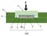
그리고 저면에 홈부가 형성된 상부 지그(7)의 홈부에 피드스루 구조물(100) 상단면을 위치시킨 후 가압하여 상부 지그(7)가 하부지그(4)의 안착홈에 끼워져 결합된 후 확산접합 공정챔버로 이송시키고, 피드스루 구조물(100)의 세라믹 구조체(1), 백금-이리듐 핀(2) 및 티타늄 플랜지(3)가 확산접합공정에 따라 상호 접합(S140)되도록 한다. 하부 지그(4)에 상부 지그(7)가 끼워져 결합되면서피드스루 구조물(100)이 외부환경으로부터 완전히 분리되어 노출되지 않게되고, 이렇게 밀폐된 상태에서 확산접합공정이 이루어지도록 한다.After the top surface of the feed-through
이때, 하부 지그(4)에는 2개의 채널(5)(6)이 형성되어 있으며, 이 2개의 채널(5)(6)은 상부 지그(7)와 하부 지그(4) 사이에 형성되는 공간상의 기체가 압력과 열을 가하는 확산접합 과정에서 외부로 배출되도록 하는 통로이다. 채널(5)은 하부 지그(4) 측면에 형성되어 있으며, 채널(6)은 하부 지그(4) 바닥면에 형성되어 있다.At this time, two
그리고 상부 지그(7)는 화살표 방향으로 압력이 가해질 수 있도록 하부 지그(4)의 상단부면보다 돌출되어 있어야 하며, 상부 지그(7), 하부지그(4), 피디스루 구조물(100)은 모두 같거나 거의 근사한 열 팽창율을 가져야 한다.The
이렇게 세라믹 구조체(1) 상부로 상부 지그(7)를 장착시킨 후 확산접합 공정챔버 내로 이송시켜 확산접합공정이 수행(S140)되도록 한 후, 열을 식히는 공정이 수행(S150)되도록 한다. 확산접합공정을 위해서는 10-5기압 이하의 고진공조건에서 950N/m2 이상의 고압력과 800℃ 이상의 열을 2시간 동안 가해 주어야 한다. 온도는 5℃/분의 속도로 증가되어 확산접합이 이루어지는 2 시간 동안 유지되도록 한다.After the
그리고 확산접합공정 수행 후 확산접합 공정챔버 내부의 온도를 낮추어 상호 접합된 피드스루 구조물(100)을 식힌다(S150). 즉, 확산접합공정 이후 1℃/분의 속도로 대략 17시간 동안 식혀진다. 열을 식히는 공정시 차가운 가스를 비롯한 차가운 환경에 노출되어서는 안되며, 1℃/분의 속도로 식힐 수 있도록 히터가 부분적으로 동작되어야 한다.After the diffusion bonding process, the temperature inside the diffusion bonding process chamber is lowered to cool the mutually bonded feed-through structure 100 (S150). That is, it is cooled at a rate of 1 deg. C / min for about 17 hours after the diffusion bonding process. The process of cooling the heat should not be exposed to cold environments, including cold gas, and the heater must be partially operated to cool down at a rate of 1 ° C / min.
그리고 식은 피드스루 구조물(100)의 세라믹 구조체(1)가 도 4에 도시된 바와 같이 레이저 가공수단에 대향되도록 위치(S160)시키고, 백금/이리듐 핀(2)이 인입된 세라믹 구조체(10) 위치로 레이저를 방사시키고, 레이저 방사에 따라 세라믹 구조체(1) 상에 홀을 형성(S170)시킨다.Then, the
그러면 세라믹 구조체(1) 상에 형성된 홀을 따라 세라믹 구조체(1) 상부로 백금-이리듐 핀(2)의 용융물이 이동되어 세라믹 구조체(1) 상부에 백금/이리듐 핀(2)의 일부를 노출(S180)시킨다. 이렇게 세라믹 구조체(1) 상부에 노출된 백금/이리듐 핀(2)의 일단(9)은 추후 전기자극회로 및 외부의 자극용 전극에 연결되는 피드스루(9)가 된다.The melt of the platinum-
상기 세라믹 구조체(1)는, 백금과 이리듐이 용융되어 세라믹 구조체(1)의 외면으로 흘러 유동되는 것을 방지하기 위해 다수 개가 세라믹 구조체(1)에 음각형성되는 유동방지홈(20)이 더 포함될 수 있다.The
상기 세라믹 구조체(1)에서 백금과 이리듐이 삽입되는 홈(10)들 사이에 형성되는 상기 유동방지홈(20)은, 상기 세라믹 구조체(1)의 백금과 이리듐이 삽입되는 홈(10)에서 백금과 이리듐이 용융될 경우, 그 용융물이 백금과 이리듐이 삽입되는 홈(10)에서 넘쳐 흘러 세라믹 구조체(1)의 외면을 타고 흐르는 것을 방지하는 기능을 수행하게 된다.The
즉, 상기 유동방지홈(20)은, 백금과 이리듐이 삽입되는 홈(10)에서 백금과 이리듐이 용융되어 넘쳐흐를 경우 백금과 이리듐 용융물이 상기 유동방지홈(20)으로 유입될 수 있도록 하여, 백금과 이리듐 용융물이 넘쳐흘러 상기 세라믹 구조체(1)의 외면을 타고 흐르는 것을 방지하게 된다.That is, when the platinum and iridium are melted and overflowed in the
이때, 상기 유동방지홈(20)의 형성되는 위치는 백금과 이리듐이 삽입되는 홈(10)과 반대되는 면에 형성될 수 있다.At this time, the position of the
그렇기 때문에, 상기 세라믹 구조체(1) 상에 레이저홀을 형성시켜 모세관 현상으로 용융된 백금과 이리듐이 레이저홀을 따라 상승하여 상기 세라믹 구조체(1)의 상부로 넘쳤을때 넘친 백금 이리듐 용융물이 상기 유동방지홈(20)으로 유입되어 인접한 다른 레이저홀을 통해 넘치는 백금 이리듐 용융물이 상호 접촉하는 것을 방지할 수 있게 되는 것이다.Therefore, a laser hole is formed on the
즉, 인접한 피드스루들은 상호 백금 이리듐 용융물이 상호 접촉되는 것이 차단되고, 상호 연결되지 않도록 하는 것이 바람직하다.
That is, adjacent feedthroughs are preferably prevented from mutual contact of the mutual platinum iridium melts and not with each other.
전술한 내용은 본 발명이 속하는 기술 분야에서 통상의 지식을 가진 자라면 본 발명의 본질적인 특성에서 벗어나지 않는 범위에서 수정 및 변형이 가능할 것이다. 따라서, 본 발명에 개시된 실시예들은 본 발명의 기술 사상을 한정하기 위한 것이 아니라 설명하기 위한 것이고, 이러한 실시예에 의하여 본 발명의 기술 사상의 범위가 한정되는 것은 아니다. 본 발명의 보호 범위는 아래의 청구범위에 의하여 해석되어야 하며, 그와 동등한 범위 내에 있는 모든 기술 사상은 본 발명의 권리범위에 포함되는 것으로 해석되어야 할 것이다.
It will be apparent to those skilled in the art that various modifications and variations can be made in the present invention without departing from the spirit or essential characteristics thereof. Therefore, the embodiments disclosed in the present invention are intended to illustrate rather than limit the scope of the present invention, and the scope of the technical idea of the present invention is not limited by these embodiments. The scope of protection of the present invention should be construed according to the following claims, and all technical ideas within the scope of equivalents should be construed as falling within the scope of the present invention.
1 : 세라믹 구조체2 : 백금/이리듐 핀
3 : 티타늄 플랜저4 : 하부 지그
5, 6 : 채널7 : 상부 지그
8 : 레이저9 : 피드스루
10, 11 : 홈
20 : 유동방지홈1: ceramic structure 2: platinum / iridium pin
3: Titanium Flanger 4: Lower jig
5, 6: channel 7: upper jig
8: Laser 9: Feedthrough
10, 11: Home
20: Floating prevention groove
Claims (5)
Translated fromKorean상기 세라믹 구조체의 복수개의 홈들에 백금 및 이리듐 합금으로 이루어진 백금-이리듐 핀을 인입시키는 단계;
상기 세라믹 구조체 상부에 티타늄으로 이루어진 티타늄 플랜지를 적층시켜, 세라믹 구조체, 백금-이리듐 핀 및 티타늄 플랜지로 이루어진 피드스루 구조물을 형성시키는 단계;
저면에 홈부가 형성된 상부 지그의 상기 홈부에 상기 피드스루 구조물 상단면을 위치시킨 후 가압하여 상기 상부 지그가 상기 하부지그의 안착홈에 끼워져 결합된 후 확산접합 공정챔버로 이송시키고, 상기 피드스루 구조물의 세라믹 구조체, 백금-이리듐 핀 및 티타늄 플랜지를 확산접합공정에 따라 상호 접합시키는 단계;
상기 확산접합공정 수행 후 확산접합 공정챔버 내부의 온도를 낮추어 상호 접합된 상기 피드스루 구조물을 식히는 단계;
식힌 상기 피드스루 구조물의 세라믹 구조체가 레이저 가공수단에 대향되도록 위치시키는 단계;
상기 백금/이리듐 핀이 인입된 상기 세라믹 구조체 위치로 레이저를 방사시키고, 상기 레이저 방사에 따라 상기 세라믹 구조체 상에 홀이 형성시키는 단계; 및
상기 세라믹 구조체 상에 형성된 홀을 따라 상기 세라믹 구조체 상부로 백금-이리듐 핀의 용융물이 이동되어 상기 세라믹 구조체 상부에 상기 백금/이리듐 핀의 일부를 노출시키는 단계;
를 포함하여 이루어진 피드스루 제조방법.
Placing a ceramic structure having a plurality of grooves at equal intervals in the seating groove of a lower jig having a seating groove formed therein;
Introducing a platinum-iridium pin made of platinum and iridium alloy into a plurality of grooves of the ceramic structure;
Depositing a titanium flange made of titanium on the ceramic structure to form a feedthrough structure comprising a ceramic structure, a platinum-iridium pin, and a titanium flange;
The upper end surface of the feed-through structure is positioned in the groove portion of the upper jig having the groove portion formed on the bottom surface thereof, and then the upper jig is inserted into the seating groove of the lower portion and then transferred to the diffusion bonding process chamber. Bonding the ceramic structure, the platinum-iridium pin, and the titanium flange according to a diffusion bonding process;
Cooling the feedthrough structure bonded together by lowering the temperature inside the diffusion bonding process chamber after performing the diffusion bonding process;
Positioning the cooled ceramic structure of the feedthrough structure so as to face the laser processing means;
Emitting a laser to the position of the ceramic structure in which the platinum / iridium pin is drawn, and forming holes on the ceramic structure according to the laser emission; And
Exposing a portion of the platinum / iridium pin to the upper portion of the ceramic structure by moving a melt of the platinum-iridium pin to the upper portion of the ceramic structure along the hole formed on the ceramic structure;
Wherein the feedthrough method comprises the steps of:
상기 백금/이리듐 핀의 끝단부와 상기 티타늄 플랜지의 끝단부가 일직선상에 위치하는 것을 특징으로 하는 피드스루 제조방법.
The method according to claim 1,
Wherein an end of the platinum / iridium fin and a tip of the titanium flange are positioned in a straight line.
상기 상부 지그 및 상기 하부 지그는 세라믹으로 이루어진 것을 특징으로 하는 피드스루 제조방법.
The method according to claim 1,
Wherein the upper jig and the lower jig are made of ceramics.
상기 상부 지그가 상기 하부 지그 상부에 끼워진 상태로 결합될 때 상기 세라믹 구조체의 일부가 상기 상부지그 외부로 노출되는 것을 특징으로 하는 피드스루 제조방법.
The method according to claim 1,
Wherein a part of the ceramic structure is exposed to the outside of the upper jig when the upper jig is engaged with the upper portion of the lower jig.
상기 세라믹 구조체는,
백금과 이리듐이 용융되어 세라믹 구조체의 외면으로 흘러 유동되는 것을 방지하기 위해 다수 개가 세라믹 구조체에 음각형성되는 유동방지홈이 더 포함되는 것을 특징으로 하는 피드스루 제조방법.
The method according to claim 1,
In the ceramic structure,
Further comprising a flow preventive groove formed in the ceramic structure so as to engage with the ceramic structure in order to prevent platinum and iridium from melting and flowing to the outer surface of the ceramic structure.
Priority Applications (4)
| Application Number | Priority Date | Filing Date | Title |
|---|---|---|---|
| KR1020150092754AKR101656723B1 (en) | 2015-06-30 | 2015-06-30 | Feedthrough making method |
| US15/739,982US10213611B2 (en) | 2015-06-30 | 2016-06-29 | Method of manufacturing feedthrough |
| EP16818197.2AEP3318305A4 (en) | 2015-06-30 | 2016-06-29 | METHOD OF MANUFACTURING CROSSING |
| PCT/KR2016/006931WO2017003164A1 (en) | 2015-06-30 | 2016-06-29 | Method for manufacturing feedthrough |
Applications Claiming Priority (1)
| Application Number | Priority Date | Filing Date | Title |
|---|---|---|---|
| KR1020150092754AKR101656723B1 (en) | 2015-06-30 | 2015-06-30 | Feedthrough making method |
Publications (1)
| Publication Number | Publication Date |
|---|---|
| KR101656723B1true KR101656723B1 (en) | 2016-09-12 |
Family
ID=56950428
Family Applications (1)
| Application Number | Title | Priority Date | Filing Date |
|---|---|---|---|
| KR1020150092754AExpired - Fee RelatedKR101656723B1 (en) | 2015-06-30 | 2015-06-30 | Feedthrough making method |
Country Status (4)
| Country | Link |
|---|---|
| US (1) | US10213611B2 (en) |
| EP (1) | EP3318305A4 (en) |
| KR (1) | KR101656723B1 (en) |
| WO (1) | WO2017003164A1 (en) |
Cited By (2)
| Publication number | Priority date | Publication date | Assignee | Title |
|---|---|---|---|---|
| KR101952930B1 (en)* | 2018-01-08 | 2019-02-28 | 주식회사 토닥 | Method for manufacturing feedthrough and a method for manufacturing sealed electric device using feedthrough manufactured by the same |
| EP3730185A1 (en)* | 2019-04-26 | 2020-10-28 | Cairdac | Implantable medical device comprising a metal/ceramics composite housing |
Families Citing this family (2)
| Publication number | Priority date | Publication date | Assignee | Title |
|---|---|---|---|---|
| CN208490858U (en)* | 2018-07-11 | 2019-02-15 | 深圳市艾维普思科技有限公司 | Atomizer and electronic cigarette |
| EP4061479A1 (en)* | 2019-11-19 | 2022-09-28 | BIOTRONIK SE & Co. KG | In situ welding for feedthrough pad attachment |
Citations (6)
| Publication number | Priority date | Publication date | Assignee | Title |
|---|---|---|---|---|
| US20110048770A1 (en)* | 2009-08-31 | 2011-03-03 | Medtronic Inc. | Injection molded ferrule for cofired feedthroughs |
| KR20130004752A (en) | 2011-07-04 | 2013-01-14 | 삼성전자주식회사 | System and method for conversing network |
| US8501547B2 (en)* | 2005-11-02 | 2013-08-06 | Second Sight Medical Products, Inc. | Implantable microelectronic device and method of manufacture |
| KR20140025466A (en) | 2011-06-10 | 2014-03-04 | 쇼오트 아게 | Feedthrough |
| US8698006B2 (en)* | 2009-06-04 | 2014-04-15 | Morgan Advanced Ceramics, Inc. | Co-fired metal and ceramic composite feedthrough assemblies for use at least in implantable medical devices and methods for making the same |
| JP2015016297A (en)* | 2011-08-02 | 2015-01-29 | メドトロニック,インク.Medtronic,Inc. | Airtight feedthrough |
Family Cites Families (126)
| Publication number | Priority date | Publication date | Assignee | Title |
|---|---|---|---|---|
| US4156429A (en)* | 1977-10-11 | 1979-05-29 | Cardiac Pacemakers, Inc. | Implantable electrode |
| EP0269007A1 (en)* | 1986-11-28 | 1988-06-01 | Siemens Aktiengesellschaft | Ceramic-metal feedthrough assembly, in particular for cardiac or neural stimulation, and method of manufacturing it |
| US5738270A (en)* | 1994-10-07 | 1998-04-14 | Advanced Bionics Corporation | Brazeless ceramic-to-metal bonding for use in implantable devices |
| US5817984A (en)* | 1995-07-28 | 1998-10-06 | Medtronic Inc | Implantable medical device wtih multi-pin feedthrough |
| US5870272A (en)* | 1997-05-06 | 1999-02-09 | Medtronic Inc. | Capacitive filter feedthrough for implantable medical device |
| US6008980A (en)* | 1997-11-13 | 1999-12-28 | Maxwell Energy Products, Inc. | Hermetically sealed EMI feedthrough filter capacitor for human implant and other applications |
| US6159560A (en)* | 1998-11-25 | 2000-12-12 | Stevenson; Robert A. | Process for depositing a metal coating on a metallic component of an electrical structure |
| US6349025B1 (en)* | 1999-11-30 | 2002-02-19 | Medtronic, Inc. | Leak testable capacitive filtered feedthrough for an implantable medical device |
| US6415182B1 (en)* | 2000-01-31 | 2002-07-02 | Cts Corporation | Hermetic ground pin assembly and method of making |
| US6516228B1 (en)* | 2000-02-07 | 2003-02-04 | Epic Biosonics Inc. | Implantable microphone for use with a hearing aid or cochlear prosthesis |
| US6414835B1 (en)* | 2000-03-01 | 2002-07-02 | Medtronic, Inc. | Capacitive filtered feedthrough array for an implantable medical device |
| JP3446713B2 (en)* | 2000-03-14 | 2003-09-16 | 株式会社村田製作所 | Ceramic electronic components with lead terminals |
| US6529103B1 (en)* | 2000-09-07 | 2003-03-04 | Greatbatch-Sierra, Inc. | Internally grounded feedthrough filter capacitor with improved ground plane design for human implant and other applications |
| US6498952B2 (en)* | 2001-03-08 | 2002-12-24 | Pacesetter, Inc. | Hermetically sealed feedthrough connector using shape memory alloy for implantable medical device |
| US6662035B2 (en)* | 2001-09-13 | 2003-12-09 | Neuropace, Inc. | Implantable lead connector assembly for implantable devices and methods of using it |
| US6985347B2 (en)* | 2002-02-28 | 2006-01-10 | Greatbatch-Sierra, Inc. | EMI filter capacitors designed for direct body fluid exposure |
| EP1488434B1 (en)* | 2002-02-28 | 2012-12-12 | Greatbatch Ltd. | Emi feedthrough filter terminal assembly utilizing hermetic seal for electrical attachment between lead wires and capacitor |
| US7146222B2 (en)* | 2002-04-15 | 2006-12-05 | Neurospace, Inc. | Reinforced sensing and stimulation leads and use in detection systems |
| US7623335B2 (en)* | 2003-02-27 | 2009-11-24 | Greatbatch-Sierra, Inc | Hermetic feedthrough terminal assembly with wire bond pads for human implant applications |
| US7038900B2 (en)* | 2003-02-27 | 2006-05-02 | Greatbatch-Sierra, Inc. | EMI filter terminal assembly with wire bond pads for human implant applications |
| US7837085B1 (en)* | 2003-04-09 | 2010-11-23 | Boston Scientific Neuromodulation Corporation | Hermetic seal |
| US20080269596A1 (en)* | 2004-03-10 | 2008-10-30 | Ian Revie | Orthpaedic Monitoring Systems, Methods, Implants and Instruments |
| US7035076B1 (en)* | 2005-08-15 | 2006-04-25 | Greatbatch-Sierra, Inc. | Feedthrough filter capacitor assembly with internally grounded hermetic insulator |
| WO2006041738A2 (en)* | 2004-10-04 | 2006-04-20 | Cyberkinetics Neurotechnology Systems, Inc. | Biological interface system |
| US7145076B2 (en) | 2005-02-08 | 2006-12-05 | Greatbatch, Inc. | Method for minimizing stress in feedthrough capacitor filter assemblies |
| US8118748B2 (en)* | 2005-04-28 | 2012-02-21 | Medtronic, Inc. | Implantable capacitive pressure sensor system and method |
| US20060247714A1 (en)* | 2005-04-28 | 2006-11-02 | Taylor William J | Glass-to-metal feedthrough seals having improved durability particularly under AC or DC bias |
| US8991680B1 (en)* | 2005-05-25 | 2015-03-31 | Alfred E. Mann Foundation For Scientific Research | Method of manufacture of an electrode array |
| US8024022B2 (en)* | 2005-05-25 | 2011-09-20 | Alfred E. Mann Foundation For Scientific Research | Hermetically sealed three-dimensional electrode array |
| US7340305B2 (en)* | 2005-06-09 | 2008-03-04 | Cardiac Pacemakers, Inc. | Implantable medical device feedthrough assembly having a coated conductor |
| US7564674B2 (en)* | 2005-12-12 | 2009-07-21 | Greatbatch Ltd. | Feedthrough filter capacitor assemblies having low cost terminal pins |
| US20070142888A1 (en)* | 2005-12-20 | 2007-06-21 | Alfonso Chavez | Implantable leads and methods of using the same |
| US20070183117A1 (en)* | 2006-02-07 | 2007-08-09 | Greatbatch Ltd. | Nano-Titanium For Making Medical Implantable Hermetic Feedthrough Assemblies |
| US20070250142A1 (en)* | 2006-03-30 | 2007-10-25 | Francis Richard W | Atomic Layer Deposition Coatings for Implantable Medical Devices |
| US8326425B2 (en)* | 2006-03-30 | 2012-12-04 | Cardiac Pacemakers, Inc. | Feedthrough connector for implantable device |
| US7818876B2 (en)* | 2006-04-25 | 2010-10-26 | Gregg Jorgen Suaning | Method for fabrication of hermetic electrical conductor feedthroughs |
| DE102006041940A1 (en)* | 2006-09-07 | 2008-03-27 | Biotronik Crm Patent Ag | Electrical implementation |
| US8000804B1 (en)* | 2006-10-27 | 2011-08-16 | Sandia Corporation | Electrode array for neural stimulation |
| WO2009003235A1 (en)* | 2007-07-02 | 2009-01-08 | Cochlear Limited | Implantable housing assembly |
| US7794256B1 (en)* | 2007-08-09 | 2010-09-14 | Jerzy Roman Sochor | Implantable connector with contact-containing feedthrough pins |
| US8267708B1 (en)* | 2007-08-09 | 2012-09-18 | Jerzy Roman Sochor | Implantable feedthrough-based connector |
| US8162684B1 (en)* | 2008-08-07 | 2012-04-24 | Jerzy Roman Sochor | Implantable connector with contact-containing feedthrough pins |
| EP2197536A1 (en)* | 2007-10-09 | 2010-06-23 | Imthera Medical, Inc. | System and method for neural stimulation |
| CN101981821B (en)* | 2008-02-01 | 2015-06-03 | 史密夫和内修有限公司 | System and method for communicating with an implant |
| US20090240099A1 (en)* | 2008-02-29 | 2009-09-24 | Otologics, Llc | Bi-modal cochlea stimulation |
| US7736191B1 (en)* | 2008-05-27 | 2010-06-15 | Jerzy Roman Sochor | Implantable connector with protected contacts |
| US8983618B2 (en)* | 2008-10-31 | 2015-03-17 | Medtronic, Inc. | Co-fired multi-layer antenna for implantable medical devices and method for forming the same |
| US20100109966A1 (en)* | 2008-10-31 | 2010-05-06 | Mateychuk Duane N | Multi-Layer Miniature Antenna For Implantable Medical Devices and Method for Forming the Same |
| US8497804B2 (en)* | 2008-10-31 | 2013-07-30 | Medtronic, Inc. | High dielectric substrate antenna for implantable miniaturized wireless communications and method for forming the same |
| US8050771B2 (en)* | 2008-12-29 | 2011-11-01 | Medtronic, Inc. | Phased array cofire antenna structure and method for operating the same |
| US8494641B2 (en)* | 2009-04-22 | 2013-07-23 | Autonomic Technologies, Inc. | Implantable neurostimulator with integral hermetic electronic enclosure, circuit substrate, monolithic feed-through, lead assembly and anchoring mechanism |
| US8095224B2 (en)* | 2009-03-19 | 2012-01-10 | Greatbatch Ltd. | EMI shielded conduit assembly for an active implantable medical device |
| US8422195B2 (en)* | 2009-12-22 | 2013-04-16 | Greatbatch Ltd. | Feedthrough flat-through capacitor |
| FR2957749A1 (en)* | 2010-03-22 | 2011-09-23 | Sorin Crm Sas | METHOD FOR PRODUCING AN ELECTRICAL CROSSROAD IN THE METAL WALL OF A HOUSING, IN PARTICULAR AN ACTIVE MEDICAL DEVICE, AND DEVICE COMPRISING SUCH A TRAVERSEE |
| EP2371417B1 (en)* | 2010-03-29 | 2019-07-24 | BIOTRONIK SE & Co. KG | Electrical feedthrough, method for the production and use thereof |
| EP2371418B1 (en)* | 2010-03-29 | 2021-11-03 | BIOTRONIK SE & Co. KG | Electrical feedthrough for electromedical implants |
| US8675338B2 (en)* | 2010-03-29 | 2014-03-18 | Biotronik Se & Co. Kg | Electrical feedthrough of a capacitor for medical implants and method for the production and use thereof |
| US8648255B2 (en)* | 2010-05-21 | 2014-02-11 | Greatbatch Ltd. | Laser beam button weld of dissimilar materials |
| US8648265B2 (en)* | 2010-06-08 | 2014-02-11 | Greatbatch Ltd. | Full perimeter laser beam button weld of dissimilar materials |
| US20110303458A1 (en)* | 2010-06-15 | 2011-12-15 | Greatbatch Ltd. | Coating of Non-Solderable Base Metal for Soldering Application in Medical Device Component |
| US8642887B1 (en)* | 2010-12-03 | 2014-02-04 | Greatbatch Ltd. | Metallization barrier for a hermetic feedthrough |
| EP2651510B1 (en)* | 2010-12-15 | 2015-11-04 | Advanced Bionics AG | Particulate toughened ceramic feedthrough |
| US9949416B2 (en)* | 2010-12-15 | 2018-04-17 | Advanced Bionics Ag | Protection for implanted gold surfaces |
| US8509899B2 (en)* | 2010-12-23 | 2013-08-13 | Medtronic, Inc. | Multi-electrode implantable systems and assemblies thereof |
| WO2012116214A1 (en)* | 2011-02-24 | 2012-08-30 | Boston Scientific Neuromodulation Corporation | Implantable neurostimulator with a circuit board and a connector |
| US10350421B2 (en)* | 2013-06-30 | 2019-07-16 | Greatbatch Ltd. | Metallurgically bonded gold pocket pad for grounding an EMI filter to a hermetic terminal for an active implantable medical device |
| US9048012B2 (en)* | 2011-04-18 | 2015-06-02 | Lawrence Livermore National Security, Llc | Method of fabricating high-density hermetic electrical feedthroughs |
| US9240630B2 (en)* | 2011-04-29 | 2016-01-19 | Cyberonics, Inc. | Antenna shield for an implantable medical device |
| WO2012158845A2 (en)* | 2011-05-16 | 2012-11-22 | Lawrence Livermore National Security, Llc | Method of fabricating high-density hermetic electrical feedthroughs using insulated wire bundles |
| US8644002B2 (en)* | 2011-05-31 | 2014-02-04 | Medtronic, Inc. | Capacitor including registration feature for aligning an insulator layer |
| US9627833B2 (en)* | 2011-08-02 | 2017-04-18 | Medtronic, Inc. | Electrical leads for a feedthrough |
| WO2013047740A1 (en)* | 2011-09-30 | 2013-04-04 | 京セラ株式会社 | Bonded body of metal and ceramic |
| FR2985855B1 (en) | 2012-01-17 | 2014-11-21 | Soc Fr Detecteurs Infrarouges Sofradir | METHOD FOR PRODUCING SEALED ELECTRIC CROSSES THROUGH AN ENCAPSULATION BOX AND ENCAPSULATION BOX PROVIDED WITH AT LEAST ONE OF THESE ELECTRICAL TRAVERSEES |
| WO2013112550A1 (en)* | 2012-01-24 | 2013-08-01 | Thoratec Corporation | Driveline cable assembly |
| US8954143B2 (en)* | 2012-03-06 | 2015-02-10 | Valencia Technologies Corporation | Radial feed through packaging for an implantable electroacupuncture device |
| US20130286536A1 (en)* | 2012-04-26 | 2013-10-31 | Medtronic, Inc. | Implantable medical device with feedthrough, feedthrough and method |
| US20150250386A1 (en)* | 2012-09-28 | 2015-09-10 | Csem Centre Suisse D'electronique Et De Microtechnique Sa -Recherche Et Developpement | Implantable devices |
| WO2014089392A1 (en)* | 2012-12-07 | 2014-06-12 | Medtronic, Inc. | Minimally invasive implantable neurostimulation system |
| US9351436B2 (en)* | 2013-03-08 | 2016-05-24 | Cochlear Limited | Stud bump bonding in implantable medical devices |
| US9878170B2 (en)* | 2013-03-15 | 2018-01-30 | Globus Medical, Inc. | Spinal cord stimulator system |
| US9517343B2 (en)* | 2013-03-15 | 2016-12-13 | Globus Medical. Inc. | Implantable pulse generator that generates spinal cord stimulation signals for a human body |
| US9872997B2 (en)* | 2013-03-15 | 2018-01-23 | Globus Medical, Inc. | Spinal cord stimulator system |
| US9270011B2 (en)* | 2013-03-15 | 2016-02-23 | Cyberonics, Inc. | Antenna coupled to a cover closing an opening in an implantable medical device |
| US9511227B2 (en)* | 2013-03-15 | 2016-12-06 | Globus Medical, Inc. | Implantable pulse generator that generates spinal cord stimulation signals for a human body |
| US10413730B2 (en)* | 2013-03-15 | 2019-09-17 | Cirtec Medical Corp. | Implantable pulse generator that generates spinal cord stimulation signals for a human body |
| US10080896B2 (en)* | 2013-03-15 | 2018-09-25 | Cirtec Medical Corp. | Implantable pulse generator that generates spinal cord stimulation signals for a human body |
| US9511232B2 (en)* | 2013-03-15 | 2016-12-06 | Globus Medical, Inc. | Implantable pulse generator that generates spinal cord stimulation signals for a human body |
| US10016604B2 (en)* | 2013-03-15 | 2018-07-10 | Globus Medical, Inc. | Implantable pulse generator that generates spinal cord stimulation signals for a human body |
| US10226628B2 (en)* | 2013-03-15 | 2019-03-12 | Cirtec Medical Corp. | Implantable pulse generator that generates spinal cord stimulation signals for a human body |
| US9517347B2 (en)* | 2013-03-15 | 2016-12-13 | Globus Medical, Inc. | Implantable pulse generator that generates spinal cord stimulation signals for a human body |
| US9887574B2 (en)* | 2013-03-15 | 2018-02-06 | Globus Medical, Inc. | Spinal cord stimulator system |
| US9440076B2 (en)* | 2013-03-15 | 2016-09-13 | Globus Medical, Inc. | Spinal cord stimulator system |
| US9526899B2 (en)* | 2013-03-15 | 2016-12-27 | Globus Medical, Inc. | Implantable pulse generator that generates spinal cord stimulation signals for a human body |
| US9381590B2 (en)* | 2013-06-14 | 2016-07-05 | Cochlear Limited | Implantable medical device feedthroughs and housings |
| US9643020B2 (en)* | 2013-08-09 | 2017-05-09 | Medtronic, Inc. | Feedthrough assembly for an implantable medical device |
| US20150045861A1 (en)* | 2013-08-09 | 2015-02-12 | Medtronic, Inc. | Feedthrough assembly for an implantable medical device |
| US9119970B2 (en)* | 2013-08-19 | 2015-09-01 | Boston Scientific Neuromodulation Corporation | Feedthrough assembly with glass layer and electrical stimulation systems containing the assembly |
| EP3403692A1 (en)* | 2013-09-26 | 2018-11-21 | Oticon Medical A/S | A device implantable under skin |
| US9138821B2 (en)* | 2014-01-17 | 2015-09-22 | Medtronic, Inc. | Methods for simultaneously brazing a ferrule and lead pins |
| US10004907B2 (en)* | 2014-02-21 | 2018-06-26 | Pacesetter, Inc. | Automatic capture verification within leadless implantable medical devices |
| JP2017514550A (en)* | 2014-03-24 | 2017-06-08 | アーキス バイオサイエンシーズ | Implantable dual sensor, biological pressure transponder and calibration method |
| FR3019375B1 (en)* | 2014-03-31 | 2016-05-06 | Commissariat Energie Atomique | METHOD FOR PRODUCING A HERMETIC CASE FOR ENCAPSULATING AN IMPLANTABLE DEVICE AND CORRESPONDING HOUSING |
| JP2017521129A (en)* | 2014-06-09 | 2017-08-03 | ザ リージェンツ オブ ザ ユニバーシティ オブ カリフォルニア | System and method for restoring cognitive function |
| US9742178B2 (en)* | 2014-07-25 | 2017-08-22 | Medtronic, Inc. | Medical device feedthrough assemblies with strain relief |
| US10064288B2 (en)* | 2014-08-12 | 2018-08-28 | Advanced Bionics Ag | Methods for connecting a wire to a feedthrough pin and apparatus including a wire connected to a feedthrough pin by the method |
| AU2015301398B2 (en)* | 2014-08-15 | 2020-05-21 | Axonics Modulation Technologies, Inc. | Implantable lead affixation structure for nerve stimulation to alleviate bladder dysfunction and other indications |
| US10682521B2 (en)* | 2014-08-15 | 2020-06-16 | Axonics Modulation Technologies, Inc. | Attachment devices and associated methods of use with a nerve stimulation charging device |
| ES2782556T3 (en)* | 2014-08-15 | 2020-09-15 | Axonics Modulation Tech Inc | System for neurostimulation electrode configurations based on neuronal location |
| AU2015301401B2 (en)* | 2014-08-15 | 2020-01-16 | Axonics Modulation Technologies, Inc. | Electromyographic lead positioning and stimulation titration in a nerve stimulation system for treatment of overactive bladder |
| CA2958210C (en)* | 2014-08-15 | 2023-09-26 | Axonics Modulation Technologies, Inc. | Integrated electromyographic clinician programmer for use with an implantable neurostimulator |
| WO2016057525A1 (en)* | 2014-10-06 | 2016-04-14 | Thoratec Corporation | Multiaxial connector for implantable devices |
| US9735477B2 (en)* | 2014-10-14 | 2017-08-15 | Biotronik Se & Co. Kg | Terminal pin, feedthrough of an implantable electromedical device and process for making the same |
| US10211068B2 (en)* | 2014-10-16 | 2019-02-19 | Mitsubishi Materials Corporation | Power-module substrate with cooler and method of producing the same |
| DE102014016600A1 (en)* | 2014-11-11 | 2016-05-12 | Schott Ag | execution |
| CA2973192C (en)* | 2015-01-09 | 2023-04-04 | Axonics Modulation Technologies, Inc. | Improved antenna and methods of use for an implantable nerve stimulator |
| CN107427675B (en)* | 2015-01-09 | 2021-10-26 | 艾克索尼克斯股份有限公司 | Patient remote control and associated method for use with a neurostimulation system |
| US10391311B2 (en)* | 2015-01-21 | 2019-08-27 | Advanced Bionics Ag | Cochlear implants |
| EP3069753A1 (en)* | 2015-03-17 | 2016-09-21 | BIOTRONIK SE & Co. KG | Implantable medical device and manufacturing method therefor |
| EP3069758A1 (en)* | 2015-03-20 | 2016-09-21 | BIOTRONIK SE & Co. KG | Stamped flange for electric feedthroughs with integrated grounding pin |
| US9985372B2 (en)* | 2015-03-20 | 2018-05-29 | BIOTRONIK SE Co. KG | Terminal pin and feedthrough |
| AU2016291554B2 (en)* | 2015-07-10 | 2021-01-07 | Axonics Modulation Technologies, Inc. | Implantable nerve stimulator having internal electronics without ASIC and methods of use |
| EP3124946B1 (en)* | 2015-07-31 | 2020-02-26 | Kistler Holding AG | Pressure sensor and method for manufacturing such a pressure sensor |
| DE102015117935A1 (en)* | 2015-10-21 | 2017-04-27 | Biotronik Se & Co. Kg | Implementation of a medical electronic device and medical electronic device |
| US10576292B2 (en)* | 2015-11-29 | 2020-03-03 | Boston Scientific Neuromodulation Corporation | Skull-mounted deep brain stimulator |
| JP6876363B2 (en)* | 2016-01-29 | 2021-05-26 | アクソニクス モジュレーション テクノロジーズ インコーポレイテッド | Methods and systems for frequency adjustment that optimize the charging of implantable neurostimulators |
| US10335607B2 (en)* | 2016-02-05 | 2019-07-02 | Boston Scientific Neuromodulation Corporation | Implantable optical stimulation lead and methods of making and using |
- 2015
- 2015-06-30KRKR1020150092754Apatent/KR101656723B1/ennot_activeExpired - Fee Related
- 2016
- 2016-06-29EPEP16818197.2Apatent/EP3318305A4/ennot_activeWithdrawn
- 2016-06-29WOPCT/KR2016/006931patent/WO2017003164A1/ennot_activeCeased
- 2016-06-29USUS15/739,982patent/US10213611B2/enactiveActive
Patent Citations (6)
| Publication number | Priority date | Publication date | Assignee | Title |
|---|---|---|---|---|
| US8501547B2 (en)* | 2005-11-02 | 2013-08-06 | Second Sight Medical Products, Inc. | Implantable microelectronic device and method of manufacture |
| US8698006B2 (en)* | 2009-06-04 | 2014-04-15 | Morgan Advanced Ceramics, Inc. | Co-fired metal and ceramic composite feedthrough assemblies for use at least in implantable medical devices and methods for making the same |
| US20110048770A1 (en)* | 2009-08-31 | 2011-03-03 | Medtronic Inc. | Injection molded ferrule for cofired feedthroughs |
| KR20140025466A (en) | 2011-06-10 | 2014-03-04 | 쇼오트 아게 | Feedthrough |
| KR20130004752A (en) | 2011-07-04 | 2013-01-14 | 삼성전자주식회사 | System and method for conversing network |
| JP2015016297A (en)* | 2011-08-02 | 2015-01-29 | メドトロニック,インク.Medtronic,Inc. | Airtight feedthrough |
Cited By (2)
| Publication number | Priority date | Publication date | Assignee | Title |
|---|---|---|---|---|
| KR101952930B1 (en)* | 2018-01-08 | 2019-02-28 | 주식회사 토닥 | Method for manufacturing feedthrough and a method for manufacturing sealed electric device using feedthrough manufactured by the same |
| EP3730185A1 (en)* | 2019-04-26 | 2020-10-28 | Cairdac | Implantable medical device comprising a metal/ceramics composite housing |
Also Published As
| Publication number | Publication date |
|---|---|
| WO2017003164A1 (en) | 2017-01-05 |
| EP3318305A1 (en) | 2018-05-09 |
| US20180185654A1 (en) | 2018-07-05 |
| US10213611B2 (en) | 2019-02-26 |
| EP3318305A4 (en) | 2019-03-06 |
Similar Documents
| Publication | Publication Date | Title |
|---|---|---|
| US9610451B2 (en) | Direct integration of feedthrough to implantable medical device housing using a gold alloy | |
| US10770879B2 (en) | Welded feedthrough | |
| US9653893B2 (en) | Ceramic feedthrough brazed to an implantable medical device housing | |
| KR101656723B1 (en) | Feedthrough making method | |
| CN102872529B (en) | Ceramic feed-through connector for implantable electrical stimulator and method for manufacturing ceramic feed-through connector | |
| US9849296B2 (en) | Directly integrated feedthrough to implantable medical device housing | |
| US9855008B2 (en) | Direct integration of feedthrough to implantable medical device housing with ultrasonic welding | |
| JP7009499B2 (en) | A substrate for the penetration of a conductor, and a housing member of a housing comprising such a substrate, especially a battery housing. | |
| US8560079B2 (en) | Braze join | |
| CN103842024A (en) | Method for interconnecting conductors and feedthroughs with pads of sufficient thickness | |
| CN102824692B (en) | Feed-through connector for implantable medical device and manufacturing method | |
| CN105579097A (en) | Method of forming feedthrough with integrated brazeless ferrule | |
| US9387336B2 (en) | Method for producing a hermetically sealed casing intended for encapsulating an implantable device, and corresponding casing |
Legal Events
| Date | Code | Title | Description |
|---|---|---|---|
| PA0109 | Patent application | St.27 status event code:A-0-1-A10-A12-nap-PA0109 | |
| PA0201 | Request for examination | St.27 status event code:A-1-2-D10-D11-exm-PA0201 | |
| PE0701 | Decision of registration | St.27 status event code:A-1-2-D10-D22-exm-PE0701 | |
| GRNT | Written decision to grant | ||
| PR0701 | Registration of establishment | St.27 status event code:A-2-4-F10-F11-exm-PR0701 | |
| PR1002 | Payment of registration fee | St.27 status event code:A-2-2-U10-U11-oth-PR1002 Fee payment year number:1 | |
| PG1601 | Publication of registration | St.27 status event code:A-4-4-Q10-Q13-nap-PG1601 | |
| R18-X000 | Changes to party contact information recorded | St.27 status event code:A-5-5-R10-R18-oth-X000 | |
| P22-X000 | Classification modified | St.27 status event code:A-4-4-P10-P22-nap-X000 | |
| FPAY | Annual fee payment | Payment date:20190715 Year of fee payment:4 | |
| PR1001 | Payment of annual fee | St.27 status event code:A-4-4-U10-U11-oth-PR1001 Fee payment year number:4 | |
| PR1001 | Payment of annual fee | St.27 status event code:A-4-4-U10-U11-oth-PR1001 Fee payment year number:5 | |
| PR1001 | Payment of annual fee | St.27 status event code:A-4-4-U10-U11-oth-PR1001 Fee payment year number:6 | |
| PR1001 | Payment of annual fee | St.27 status event code:A-4-4-U10-U11-oth-PR1001 Fee payment year number:7 | |
| PR1001 | Payment of annual fee | St.27 status event code:A-4-4-U10-U11-oth-PR1001 Fee payment year number:8 | |
| PC1903 | Unpaid annual fee | St.27 status event code:A-4-4-U10-U13-oth-PC1903 Not in force date:20240907 Payment event data comment text:Termination Category : DEFAULT_OF_REGISTRATION_FEE | |
| PC1903 | Unpaid annual fee | St.27 status event code:N-4-6-H10-H13-oth-PC1903 Ip right cessation event data comment text:Termination Category : DEFAULT_OF_REGISTRATION_FEE Not in force date:20240907 |