KR101656577B1 - Antenna including frequency selective resonator - Google Patents
Antenna including frequency selective resonatorDownload PDFInfo
- Publication number
- KR101656577B1 KR101656577B1KR1020140149555AKR20140149555AKR101656577B1KR 101656577 B1KR101656577 B1KR 101656577B1KR 1020140149555 AKR1020140149555 AKR 1020140149555AKR 20140149555 AKR20140149555 AKR 20140149555AKR 101656577 B1KR101656577 B1KR 101656577B1
- Authority
- KR
- South Korea
- Prior art keywords
- frequency selective
- selective resonator
- resonator
- radiator
- antenna
- Prior art date
- Legal status (The legal status is an assumption and is not a legal conclusion. Google has not performed a legal analysis and makes no representation as to the accuracy of the status listed.)
- Expired - Fee Related
Links
Images


Classifications
- H—ELECTRICITY
- H01—ELECTRIC ELEMENTS
- H01Q—ANTENNAS, i.e. RADIO AERIALS
- H01Q3/00—Arrangements for changing or varying the orientation or the shape of the directional pattern of the waves radiated from an antenna or antenna system
- H01Q3/26—Arrangements for changing or varying the orientation or the shape of the directional pattern of the waves radiated from an antenna or antenna system varying the relative phase or relative amplitude of energisation between two or more active radiating elements; varying the distribution of energy across a radiating aperture
- H—ELECTRICITY
- H01—ELECTRIC ELEMENTS
- H01Q—ANTENNAS, i.e. RADIO AERIALS
- H01Q13/00—Waveguide horns or mouths; Slot antennas; Leaky-waveguide antennas; Equivalent structures causing radiation along the transmission path of a guided wave
- H01Q13/08—Radiating ends of two-conductor microwave transmission lines, e.g. of coaxial lines, of microstrip lines
Landscapes
- Variable-Direction Aerials And Aerial Arrays (AREA)
Abstract
Translated fromKoreanDescription
Translated fromKorean본 발명은 안테나에 관한 것으로서, 더욱 상세하게는 주파수 선택 공진기를 포함하는 안테나에 관한 것이다.
The present invention relates to an antenna, and more particularly, to an antenna including a frequency selective resonator.
안테나의 이득은 안테나의 빔을 특정한 방향성을 가지고 방사하고자 할 때 매우 중요한 파라미터이다. 이동통신 시스템에서의 기지국 안테나, 위성 안테나 등은 특정 방향으로 높은 이득의 빔을 방사하는 것이 요구되며, 이에 따라 안테나의 이득을 향상시키기 위한 다양한 연구가 시도되었다.The gain of the antenna is a very important parameter when it is desired to radiate the beam of the antenna with a specific directionality. A base station antenna and a satellite antenna in a mobile communication system are required to radiate a beam having a high gain in a specific direction, and various studies have been made to improve the gain of the antenna.
안테나의 이득을 특정 방향으로 향상시키기 위한 종래의 구조 중 가장 일반적인 구조는 다수의 어레이 방사체를 이용하는 구조이다. 어레이 방사체를 형성하고 각 방사체의 빔 패턴을 조절할 경우 특정 방향으로 높은 방사 이득을 가지는 방사 패턴의 구현이 가능하다.The most common structure among the conventional structures for improving the gain of an antenna in a specific direction is a structure using a plurality of array radiators. When the array radiator is formed and the beam pattern of each radiator is adjusted, it is possible to realize a radiation pattern having a high radiation gain in a specific direction.
그러나, 이러한 구조의 안테나는 다수의 방사체를 필요로 하며 각 방사체의 전기적 틸팅(Tilting)을 위한 페이즈 시프터를 요구하게 되어 상당한 비용이 소요될 수 밖에 없으며, 큰 사이즈를 요구하게 된다.However, the antenna of such a structure requires a large number of radiators and requires a phase shifter for electrical tilting of each radiator, which requires considerable cost and requires a large size.
근래에 들어, 기지국 과 같은 송신 장치들도 소형화 추세에 있어서 어레이 방사체가 사용될 수 있는 환경은 매우 제한되었다.In recent years, the environments in which the array radiators can be used in a miniaturization trend are also very limited.
한편, 어레이 방사체를 사용하지 않고 안테나의 이득을 향상시키는 다양한 연구가 시도되었으나 제한된 공간에서 만족할만한 성능을 제공하는 구조에 대한 연구는 미흡하였다.
On the other hand, various studies have been made to improve the gain of an antenna without using an array radiator, but studies on a structure providing a satisfactory performance in a limited space have been insufficient.
본 발명은 제한된 공간에서 안테나의 이득을 향상시키고 빔 방향을 효율적으로 제어할 수 있는 안테나를 제공한다.The present invention provides an antenna capable of improving gain of an antenna and controlling beam direction efficiently in a limited space.
또한, 본 발명은 어레이 방사체를 사용하지 않고 안테나의 이득을 향상시키고 빔 방향을 제어할 수 있는 안테나를 제공한다.
The present invention also provides an antenna capable of improving the gain of an antenna and controlling the beam direction without using an array radiator.
상기한 목적을 달성하기 위해 본 발명의 일 실시예에 따르면, 접지면; 상기 접지면상에 위치하는 방사체; 및 상기 방사체의 제1 측부에 위치하는 주파수 선택 공진기-상기 주파수 선택 공진기는 상기 접지면 및 상기 방사체와 이격됨-를 포함하되, 상기 주파수 선택 공진기는 다수의 유닛셀을 포함하는 주파수 선택 공진기를 포함하는 안테나가 제공된다.In order to achieve the above object, according to an embodiment of the present invention, A radiator positioned on the ground plane; And a frequency selective resonator located on a first side of the radiator, the frequency selective resonator being spaced apart from the ground plane and the radiator, wherein the frequency selective resonator comprises a frequency selective resonator comprising a plurality of unit cells Is provided.
상기 안테나는, 상기 다수의 유닛셀 중 2개를 연결하는 적어도 하나의 제1 리액티브 소자를 더 포함한다.The antenna further includes at least one first reactive element connecting two of the plurality of unit cells.
가변 캐패시터를 포함한다.And a variable capacitor.
상기 안테나는, 상기 방사체의 상기 제1 측부와 대향하는 제2 측부에 위치하는 제2 주파수 선택 공진기-상기 제 2 주파수 선택 공진기는 상기 접지면 및 상기 방사체와 이격됨-를 더 포함한다.The antenna further includes a second frequency selective resonator located at a second side opposite the first side of the radiator, the second frequency selective resonator being spaced apart from the ground plane and the radiator.
상기 제2 주파수 선택 공진기는 다수의 유닛셀을 포함하며, 상기 다수의 유닛셀 중 2개의 유닛셀을 연결하는 적어도 하나의 제2 리액티브 소자를 더 포함한다.The second frequency selective resonator further includes a plurality of unit cells and at least one second reactive element connecting two of the plurality of unit cells.
상기 안테나는, 상기 제1 주파수 선택 공진기에 인접하며 상기 제1 주파수 선택 공진기에 비해 상기 방사체로부터 더 멀리 이격되어 위치하는 제3 주파수 선택 공진기; 및 상기 제2 주파수 선택 공진기에 인접하며 상기 제2 주파수 선택 공진기에 비해 상기 방사체로부터 더 멀리 이격되어 위치하는 제4 주파수 선택 공진기를 더 포함한다.The antenna further comprising: a third frequency selective resonator adjacent the first frequency selective resonator and located further away from the radiator than the first frequency selective resonator; And a fourth frequency selective resonator adjacent to the second frequency selective resonator and spaced further from the radiator than the second frequency selective resonator.
상기 제1 주파수 선택 공진기 및 상기 제2 주파수 선택 공진기는 내부 공진기로 동작하고 상기 제3 주파수 선택 공진기 및 상기 제4 주파수 선택 공진기는 외부 공진기로 동작한다.The first frequency selective resonator and the second frequency selective resonator operate as an internal resonator, and the third frequency selective resonator and the fourth frequency selective resonator operate as external resonators.
본 발명의 다른 측면에 따르면, 방사체; 및 상기 방사체의 제1 측부에 상기 방사체와 이격되어 위치하는 주파수 선택 공진기를 포함하되, 상기 주파수 선택 공진기는 다수의 유닛셀을 포함하는 주파수 선택 공진기를 포함하는 안테나가 제공된다.
According to another aspect of the present invention, there is provided a semiconductor device comprising: a radiator; And a frequency selective resonator located on the first side of the radiator and spaced apart from the radiator, wherein the frequency selective resonator comprises a frequency selective resonator comprising a plurality of unit cells.
본 발명의 안테나에 따르면, 제한된 공간에서 안테나의 이득을 향상시키고 빔 방향을 효율적으로 제어할 수 있는 장점이 있다.
According to the antenna of the present invention, there is an advantage that the antenna gain can be improved and the beam direction can be efficiently controlled in a limited space.
도 1은 본 발명의 제1 실시예에 따른 주파수 선택 공진기를 포함하는 안테나의 구조를 도시한 사시도.
도 2는 본 발명의 제2 실시예에 따른 주파수 선택 공진기를 포함하는 안테나의 구조를 도시한 사시도.
도 3은 본 발명의 제3 실시예에 따른 주파수 선택 공진기를 포함하는 안테나의 구조를 도시한 사시도.
도 4는 본 발명의 제2 실시예에 따른 주파수 선택 공진기의 개념도를 도시한 도면.
도 5는 본 발명의 제2 실시예에 따른 안테나에서 제1 주파수 선택 공진기 및 제2 주파수 선택 공진기 사이의 거리에 따른 안티 공진 주파수의 변화를 도시한 도면.
도 6은 본 발명의 제3 실시예에 따른 안테나의 S11 파라미터를 도시한 그래프.1 is a perspective view illustrating a structure of an antenna including a frequency selective resonator according to a first embodiment of the present invention.
FIG. 2 is a perspective view illustrating a structure of an antenna including a frequency selective resonator according to a second embodiment of the present invention. FIG.
3 is a perspective view illustrating a structure of an antenna including a frequency selective resonator according to a third embodiment of the present invention.
4 is a conceptual diagram of a frequency selective resonator according to a second embodiment of the present invention.
5 is a graph showing changes in anti-resonance frequency according to a distance between a first frequency selective resonator and a second frequency selective resonator in an antenna according to a second embodiment of the present invention.
6 is a graph showing S11 parameters of an antenna according to a third embodiment of the present invention.
본 발명은 다양한 변경을 가할 수 있고 여러 가지 실시예를 가질 수 있는 바, 특정 실시예들을 도면에 예시하고 상세한 설명에 상세하게 설명하고자 한다. 그러나, 이는 본 발명을 특정한 실시 형태에 대해 한정하려는 것이 아니며, 본 발명의 사상 및 기술 범위에 포함되는 모든 변경, 균등물 내지 대체물을 포함하는 것으로 이해되어야 한다. 각 도면을 설명하면서 유사한 참조부호를 유사한 구성요소에 대해 사용하였다.While the invention is susceptible to various modifications and alternative forms, specific embodiments thereof are shown by way of example in the drawings and will herein be described in detail. It should be understood, however, that the invention is not intended to be limited to the particular embodiments, but includes all modifications, equivalents, and alternatives falling within the spirit and scope of the invention. Like reference numerals are used for like elements in describing each drawing.
이하에서, 본 발명에 따른 실시예들을 첨부된 도면을 참조하여 상세하게 설명한다.Hereinafter, embodiments according to the present invention will be described in detail with reference to the accompanying drawings.
도 1은 본 발명의 제1 실시예에 따른 주파수 선택 공진기를 포함하는 안테나의 구조를 도시한 사시도이다.1 is a perspective view illustrating a structure of an antenna including a frequency selective resonator according to a first embodiment of the present invention.
도 1을 참조하면, 본 발명의 일 실시예에 따른 주파수 선택 공진기를 포함하는 안테나는, 접지면(100), 방사체(110) 및 주파수 선택 공진기(120)를 포함한다.Referring to FIG. 1, an antenna including a frequency selective resonator according to an embodiment of the present invention includes a
접지면(100)은 본 발명의 일 실시예에 따른 안테나의 바닥부에 형성된다. 접지면(100)은 금속 재질로 이루어지며 접지와 전기적으로 연결되어 접지 전압을 제공한다. 예를 들어, 접지면(100)은 급전 신호를 제공하는 급전 케이블의 외심(접지 연결 부위)와 전기적으로 연결될 수 있다.The
본 발명의 안테나가 기지국에 설치되는 안테나로 활용될 경우, 접지면(100)은 기지국 안테나의 반사판일 수 있다. 본 발명의 안테나가 기판에 결합되는 단말기 안테나일 경우 접지면(100)은 기판상에 형성되는 금속면일 수 있다.When the antenna of the present invention is used as an antenna installed in a base station, the
방사체(110)는 RF 신호를 급전받아 외부에 방사하고 외부로부터 RF 신호를 수신하는 기능을 한다. 방사체(110)는 접지면상에 형성되고 방사체의 적어도 일부는 접지면(100)과 결합될 수 있다. 방사체(110)는 접지면에 수직으로 세워진 구조를 가질 수 있으나 이에 한정되는 것은 아니다.The
도 1을 참조하면, 다이폴 구조의 방사체(110)가 도시되어 있다. 물론 다이폴 구조의 방사체 이외에도 다양한 구조의 방사체가 본 발명에 사용될 수 있다는 점은 당업자에게 있어 자명할 것이며 도 1에 도시된 방사체는 예시적인 방사체일 뿐이다.Referring to Figure 1, a
다이폴 방사체(110)는 두 개의 엘리먼트로 이루어지며, 제1 엘리먼트는 접지면과 전기적으로 연결되고, 제2 엘리먼트는 급전선과 전기적으로 연결된다. 예를 들어, 방사체(110)에서 급전선과 연결되는 제2 엘리먼트는 접지면 하부의 급전선과 전기적으로 연결될 수 있다.The
주파수 선택 공진기(120)는 방사체(110)의 일측면에 설치된다. 주파수 선택 공진기(120)는 접지면과 소정 거리 이격되어 배치되며, 주파수 선택 공진기(120)를 접지면과 소정 거리 이격시키기 위해 지지대(150, 160)가 접지면(100)상에 설치될 수 있다.The frequency
지지대(150, 160)는 유전체 재질로 이루어지며, 예를 들어 아크릴 재질이 지지대로 사용될 수 있다.The
주파수 선택 공진기(120)는 유전체 재질의 바디부(121)의 다수의 유닛셀(122)이 소정 간격을 두고 배열된 형태를 가진다. 유닛셀(122)은 금속 재질로 이루어지며 도 1에는 직사각형 형태의 유닛셀(122)이 도시되어 있으나 유닛셀의 형태가 이에 한정되지는 않는다.The frequency
방사체(110)의 일 측면에 배치되는 주파수 선택 공진기(120)는 방사체(110) 주빔의 이득을 향상시키는 기능을 한다. 도 1에서, 방사체(110)이 주 빔은 +z 방향으로 형성되며, 방사체(110)의 측면에 배열되는 유닛셀로 이루어진 주파수 선택 공진기(120)에 의해 +z 방향으로의 이득이 향상될 수 있다.The frequency
방사 이득은 유닛셀의 개수, 방사체(110)와 주파수 선택 공진기(120)간의 거리 및 유닛셀의 사이즈 등에 의해 결정될 수 있다.The radiation gain may be determined by the number of unit cells, the distance between the
본 발명의 바람직한 실시예에 따르면, 주파수 선택 공진기(120)의 유닛셀 간에는 캐패시터 및 인덕터와 같은 리액티브 소자(180)가 결합될 수 있다. 바람직하게는 리액티브 소자(180)는 가변 캐패시터일 수 있다.According to a preferred embodiment of the present invention, a
리액티브 소자(180)의 인덕턴스 또는 캐패시턴스값을 조절하는 것에 의해 방사체(110)의 주빔의 방향을 조절하는 것이 가능하다. 가변 캐패시터가 리액티브 소자(180)로 사용될 경우 안테나가 설치된 상태에서 캐패시턴스를 조절하여 원하는 방향으로 주빔의 방향을 제어할 수 있다. 다수의 유닛셀(122)이 사용될 때 리액티스 소자(180)는 다수개가 유닛셀간에 결합될 수도 있으며, 필요에 따라 단일의 리액티브 소자만이 결합될 수도 있을 것이다.It is possible to adjust the direction of the main beam of the
특정 방향으로의 방사 이득을 향상시키기 위해 종래에 가장 일반적으로 사용되었던 구조는 다수의 어레이 방사체를 사용하는 구조이다. 이와 같은 어레이 방사체 구조에서 주빔의 방사 이득의 방향 및 값을 변경하기 위해서는 페이즈 시프터와 같은 위상 조절 장치가 사용되어야 하였다.The most commonly used structure to improve radiation gain in a particular direction is a structure using a plurality of array radiators. In order to change the direction and value of the radiation gain of the main beam in such an array radiator structure, a phase adjusting device such as a phase shifter has to be used.
그러나, 본 발명에 의한 주파수 선택 공진기(120가 사용될 경우 어레이 구조 및 페이즈 시프터가 사용되지 않더라도 주빔의 방향 및 방사 이득을 조절하는 것이 가능하다.However, it is possible to adjust the direction and the radiation gain of the main beam even if the array structure and the phase shifter are not used when the frequency
한편, 도 1에서는 접지면(100)상에 방사체(110)가 배치되고 접지면(100)과 이격되어 주파수 선택 공진기(120)가 배치되는 구조에 대해 설명하였다.1, the structure in which the
도 1에 도시된 안테나의 접지면은 주빔의 방향을 방사체의 상부인 +z 방향으로 설정하기 위한 안테나이다. 안테나의 주빔의 방향을 +z 및 z 방향으로 설정하고자 할 경우 접지면은 생략되어도 무방하다.The ground plane of the antenna shown in FIG. 1 is an antenna for setting the direction of the main beam in the + z direction which is the upper part of the radiator. When the direction of the main beam of the antenna is set in the + z and -z directions, the ground plane may be omitted.
도 2는 본 발명의 제2 실시예에 따른 주파수 선택 공진기를 포함하는 안테나의 구조를 도시한 사시도이다.2 is a perspective view illustrating the structure of an antenna including a frequency selective resonator according to a second embodiment of the present invention.
도 2를 참조하면, 본 발명의 제2 실시예에 따른 주파수 선택 공진기를 포함하는 안테나는, 접지면(100), 방사체(110) 및 제1 주파수 선택 공진기(120) 및 제2 주파수 선택 공진기(130)를 포함한다.2, an antenna including a frequency selective resonator according to a second exemplary embodiment of the present invention includes a
제2 실시예에 따른 안테나는 2개의 주파수 선택 공진기(120, 130)가 사용되는 구조이다. 제2 실시예에서, 제1 주파수 선택 공진기(120) 및 제2 주파수 선택 공진기(130)는 방사체(110)의 양측면에 설치된다. 제1 주파수 선택 공진기(120) 및 제2 주파수 선택 공진기(130)는 접지면과 소정 거리 이격되어 배치되며, 제1 주파수 선택 공진기(120) 및 제2 주파수 선택 공진기(130)를 접지면과 소정 거리 이격시키기 위해 지지대(150, 160, 170, 180)가 접지면(100)상에 설치될 수 있다.The antenna according to the second embodiment is a structure in which two frequency
제1 주파수 선택 공진기(120)는 방사체(110)의 제1 측면에 방사체(110)와 소정 거리 이격되어 배치되며, 제2 주파수 선택 공진기(130)는 상기 제1 측면에 대향하는 방사체(110)의 제2 측면에 소정 거리 이격되어 배치된다.The first frequency
제1 주파수 선택 공진기(120) 및 제2 주파수 선택 공진기(130)는 대칭 형태를 가질 수도 있으며 서로 다른 형태를 가질 수도 있다. 다만, 제1 주파수 선택 공진기(120) 및 제2 주파수 선택 공진기(130) 모두 다수의 유닛셀이 배열된 형태라는 점에서는 동일하다.The first frequency
제1 주파수 선택 공진기(120) 및 제2 주파수 선택 공진기(130)가 방사체의 양 측면에 배치될 때 보다 양호한 방사 이득을 달성할 수 있다.A better radiation gain can be achieved when the first frequency
제1 실시예에서와 같이 제1 주파수 선택 공진기(120) 및 제2 주파수 선택 공진기의 유닛셀간에도 리액티브 소자가 결합될 수 있으며, 리액티브 소자는 주빔의 방향을 제어하는데 이용될 수 있다.A reactive element may be coupled between the unit cells of the first frequency
도 4는 본 발명의 제2 실시예에 따른 주파수 선택 공진기의 개념도를 도시한 도면이다.4 is a conceptual diagram of a frequency selective resonator according to a second embodiment of the present invention.
도 4의 (a)에는 접지면이 존재하는 경우의 주파수 선택 공진기의 개념도가 도시되어 있으며, 도 4의 (b)에는 접지면이 존재하지 않는 경우의 주파수 선택 공진기의 개념도가 도시되어 있다.Fig. 4A is a conceptual view of a frequency selective resonator when a ground plane exists, and Fig. 4B is a conceptual diagram of a frequency selective resonator in a case where a ground plane is not present.
도 4의 (a)를 참조하면, 제1 주파수 선택 공진기(120)와 제2 주파수 선택 공진기(130)는 소정 거리 이격되며, 주빔은 제1 주파수 선택 공진기(120)와 제2 주파수 선택 공진기(130) 사이에서 z 방향으로 설정된다.Referring to FIG. 4A, the first frequency
도 4의 (b)를 참조하면, 제1 주파수 선택 공진기(120) 및 제2 주파수 선택 공진기(130)는 소정 거리 이격되며, 주빔은 제1 주파수 선택 공진기 (120)와 제2 주파수 선택 공진기(130) 사이에서 +z 방향 및 z 방향으로 설정된다.Referring to FIG. 4B, the first frequency
제2 실시예와 같이, 두 개의 주파수 선택 공진기(120, 130)가 방사체의 양 측면에 위치하는 구조는 안티 공진 특성을 이용한다. 원하는 주파수에서 안티 공진을 구현하기 위해서는 제1 주파수 선택 공진기(120) 및 제2 주파수 선택 공진기(130) 사이의 거리가 적절하게 설정되어야 한다.As in the second embodiment, the structure in which the two frequency
적절한 안티 공진 주파수를 설정하기 위한 제1 주파 선택 공진기(120) 및 제2 주파수 선택 공진기(130) 사이의 거리(g1)는 다음의 수학식 1과 같이 설정될 수 있다.The distance g1 between the first frequency

위 수학식 1에서, c는 속도이고, f는 주파수

도 5는 본 발명의 제2 실시예에 따른 안테나에서 제1 주파수 선택 공진기 및 제2 주파수 선택 공진기 사이의 거리에 따른 안티 공진 주파수의 변화를 도시한 도면이다.FIG. 5 is a diagram illustrating a change in anti-resonance frequency according to a distance between a first frequency selective resonator and a second frequency selective resonator in an antenna according to a second embodiment of the present invention.
도 5에 도시된 바와 같이, 제1 주파수 선택 공진기와 제2 주파수 선택 공진기 사이의 거리가 짧을수록 안티 공진 주파수가 상승하는 것을 확인할 수 있다.As shown in FIG. 5, it can be seen that the anti-resonance frequency increases as the distance between the first frequency selective resonator and the second frequency selective resonator becomes shorter.
도 3은 본 발명의 제3 실시예에 따른 주파수 선택 공진기를 포함하는 안테나의 구조를 도시한 사시도이다.3 is a perspective view illustrating a structure of an antenna including a frequency selective resonator according to a third embodiment of the present invention.
도 3을 참조하면, 본 발명의 제3 실시예에 따른 주파수 선택 공진기를 포함하는 안테나는, 접지면(100), 방사체(110) 및 제1 주파수 선택 공진기(120) 및 제2 주파수 선택 공진기(130), 제3 주파수 선택 공진기(140) 및 제4 주파수 선택 공진기(150)를 포함할 수 있다.3, an antenna including a frequency selective resonator according to a third exemplary embodiment of the present invention includes a
제3 실시예에 따른 안테나는 제2 실시예에 비해 제3 주파수 선택 공진기(140) 및 제4 주파수 선택 공진기(150)가 추가적으로 설치된 안테나이다.The antenna according to the third embodiment is an antenna in which a third frequency
제3 주파수 선택 공진기(140)는 제1 주파수 선택 공진기(120)의 외부에 인접한다. 제4 주파수 선택 공진기(150)는 제2 주파수 선택 공진기(130)의 외부에 위치한다.The third frequency
제3 실시예에서, 제1 주파수 선택 공진기(120) 및 제2 주파수 선택 공진기(130)는 내부 공진기로 동작하며, 제3 주파수 선택 공진기(140) 및 제4 주파수 선택 공진기(150)는 외부 공진기로 동작한다.In the third embodiment, the first frequency
제3 실시예와 같이 외부 공진기 및 내부 공진기를 함께 구비하는 구조는 양호한 임피던스 매칭을 제공하고자 할 때 사용될 수 있다.The structure including the external resonator and the internal resonator together as in the third embodiment can be used to provide a good impedance matching.
물론, 공진기의 개수가 더 증가될 수도 있다는 점은 당업자에게 있어 자명할 것이다.Of course, it will be apparent to those skilled in the art that the number of resonators may be further increased.
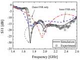
도 6은 본 발명의 제3 실시예에 따른 안테나의 S11 파라미터를 도시한 그래프이다.6 is a graph showing S11 parameters of an antenna according to a third embodiment of the present invention.
도 6에는, 본 발명의 제3 실시예에 따른 외부 공진기 및 내부 공진기를 포함하는 주파수 선택 공진기가 사용되는 경우와 외부 공진기만 사용되는 경우 및 내부 공진기만 사용되는 경우가 함께 도시되어 있다.6 shows a case where a frequency selective resonator including an external resonator and an internal resonator according to the third embodiment of the present invention, an external resonator only, and an internal resonator alone are used.
도 6을 참조하면, 외부 공진기 및 외부 공진기가 함께 사용될 때 두 개의 공진 대역인 1.7GHz 및 2.0Ghz에서 양호한 임피던스 매칭이 이루어지는 것을 확인할 수 있다.Referring to FIG. 6, when an external resonator and an external resonator are used together, it is confirmed that good impedance matching is achieved at two resonance bands, 1.7 GHz and 2.0 GHz.
이상과 같이 본 발명에서는 구체적인 구성 요소 등과 같은 특정 사항들과 한정된 실시예 및 도면에 의해 설명되었으나 이는 본 발명의 보다 전반적인 이해를 돕기 위해서 제공된 것일 뿐, 본 발명은 상기의 실시예에 한정되는 것은 아니며, 본 발명이 속하는 분야에서 통상적인 지식을 가진 자라면 이러한 기재로부터 다양한 수정 및 변형이 가능하다. 따라서, 본 발명의 사상은 설명된 실시예에 국한되어 정해져서는 아니되며, 후술하는 특허청구범위뿐 아니라 이 특허청구범위와 균등하거나 등가적 변형이 있는 모든 것들은 본 발명 사상의 범주에 속한다고 할 것이다.
As described above, the present invention has been described with reference to particular embodiments, such as specific elements, and specific embodiments and drawings. However, it should be understood that the present invention is not limited to the above- And various modifications and changes may be made thereto by those skilled in the art to which the present invention pertains. Accordingly, the spirit of the present invention should not be construed as being limited to the embodiments described, and all of the equivalents or equivalents of the claims, as well as the following claims, belong to the scope of the present invention .
Claims (12)
Translated fromKorean상기 접지면상에 위치하는 방사체; 및
상기 방사체의 제1 측부에 위치하는 제1 주파수 선택 공진기-상기 주파수 선택 공진기는 상기 접지면 및 상기 방사체와 이격됨-를 포함하되,
상기 제1 주파수 선택 공진기는 유전체 재질로 이루어지는 바디부 및 상기 바디부에 소정 간격을 두고 배열되는 다수의 유닛셀을 포함하는 것을 특징으로 하는 주파수 선택 공진기를 포함하는 안테나.
Ground plane;
A radiator positioned on the ground plane; And
A first frequency selective resonator located on a first side of the radiator, the frequency selective resonator being spaced apart from the ground plane and the radiator,
Wherein the first frequency selective resonator comprises a body part made of a dielectric material and a plurality of unit cells arranged at a predetermined interval in the body part.
상기 다수의 유닛셀 중 2개를 연결하는 적어도 하나의 제1 리액티브 소자를 더 포함하는 것을 특징으로 하는 주파수 선택 공진기를 포함하는 안테나.
The method according to claim 1,
And at least one first reactive element connecting two of the plurality of unit cells. ≪ Desc / Clms Page number 13 >
상기 리액티브 소자는 가변 캐패시터를 포함하는 것을 특징으로 하는 주파수 선택 공진기를 포함하는 안테나.
3. The method of claim 2,
Wherein the active element comprises a variable capacitor. ≪ Desc / Clms Page number 21 >
상기 방사체의 상기 제1 측부와 대향하는 제2 측부에 위치하는 제2 주파수 선택 공진기-상기 제 2 주파수 선택 공진기는 상기 접지면 및 상기 방사체와 이격됨-를 더 포함하는 것을 특징으로 하는 주파수 선택 공진기를 포함하는 안테나.
The method according to claim 1,
A second frequency selective resonator located at a second side of the radiator opposite the first side, the second frequency selective resonator being spaced apart from the ground plane and the radiator. / RTI >
상기 제2 주파수 선택 공진기는 다수의 유닛셀을 포함하며, 상기 다수의 유닛셀 중 2개의 유닛셀을 연결하는 적어도 하나의 제2 리액티브 소자를 더 포함하는 것을 특징으로 하는 주파수 선택 공진기를 포함하는 안테나.
5. The method of claim 4,
Wherein the second frequency selective resonator further comprises a plurality of unit cells and at least one second reactive element connecting two unit cells of the plurality of unit cells, antenna.
상기 제1 주파수 선택 공진기에 인접하며 상기 제1 주파수 선택 공진기에 비해 상기 방사체로부터 더 멀리 이격되어 위치하는 제3 주파수 선택 공진기; 및
상기 제2 주파수 선택 공진기에 인접하며 상기 제2 주파수 선택 공진기에 비해 상기 방사체로부터 더 멀리 이격되어 위치하는 제4 주파수 선택 공진기를 더 포함하는 것을 특징으로 하는 주파수 선택 공진기를 포함하는 안테나.
5. The method of claim 4,
A third frequency selective resonator adjacent to the first frequency selective resonator and located further away from the emitter than the first frequency selective resonator; And
And a fourth frequency selective resonator adjacent to the second frequency selective resonator and spaced further from the radiator than the second frequency selective resonator.
상기 제1 주파수 선택 공진기 및 상기 제2 주파수 선택 공진기는 내부 공진기로 동작하고 상기 제3 주파수 선택 공진기 및 상기 제4 주파수 선택 공진기는 외부 공진기로 동작하는 것을 특징으로 하는 주파수 선택 공진기를 포함하는 안테나.
The method according to claim 6,
Wherein the first frequency selective resonator and the second frequency selective resonator operate as an internal resonator and the third frequency selective resonator and the fourth frequency selective resonator operate as external resonators.
상기 방사체의 제1 측부에 상기 방사체와 이격되어 위치하는 제1 주파수 선택 공진기를 포함하되,
상기 제1 주파수 선택 공진기는 유전체 재질로 이루어지는 바디부 및 상기 바디부에 소정 간격을 두고 배열되는 다수의 유닛셀을 포함하며, 상기 유닛셀은 접지 및 급전과 전기적으로 연결되지 않는 것을 포함하는 것을 특징으로 하는 주파수 선택 공진기를 포함하는 안테나.
Radiators; And
And a first frequency selective resonator located on a first side of the radiator, the first frequency selective resonator being spaced apart from the radiator,
The first frequency selective resonator may include a body part made of a dielectric material and a plurality of unit cells arranged at a predetermined interval in the body part, wherein the unit cell is not electrically connected to ground and power supply And a frequency selective resonator.
상기 다수의 유닛셀 중 2개를 연결하는 적어도 하나의 제1 리액티브 소자를 더 포함하는 것을 특징으로 하는 주파수 선택 공진기를 포함하는 안테나.
9. The method of claim 8,
And at least one first reactive element connecting two of the plurality of unit cells. ≪ Desc / Clms Page number 13 >
상기 리액티브 소자는 가변 캐패시터를 포함하는 것을 특징으로 하는 주파수 선택 공진기를 포함하는 안테나.
10. The method of claim 9,
Wherein the active element comprises a variable capacitor. ≪ Desc / Clms Page number 21 >
상기 방사체의 상기 제1 측부와 대향하는 제2 측부에 위치하는 제2 주파수 선택 공진기를 더 포함하는 것을 특징으로 하는 주파수 선택 공진기를 포함하는 안테나.
9. The method of claim 8,
And a second frequency selective resonator located on a second side of the radiator opposite the first side.
상기 제1 주파수 선택 공진기에 인접하며 상기 제1 주파수 선택 공진기에 비해 상기 방사체로부터 더 멀리 이격되어 위치하는 제3 주파수 선택 공진기; 및
상기 제2 주파수 선택 공진기에 인접하며 상기 제2 주파수 선택 공진기에 비해 상기 방사체로부터 더 멀리 이격되어 위치하는 제4 주파수 선택 공진기를 더 포함하는 것을 특징으로 하는 주파수 선택 공진기를 포함하는 안테나.
12. The method of claim 11,
A third frequency selective resonator adjacent to the first frequency selective resonator and located further away from the emitter than the first frequency selective resonator; And
And a fourth frequency selective resonator adjacent to the second frequency selective resonator and spaced further from the radiator than the second frequency selective resonator.
Priority Applications (1)
| Application Number | Priority Date | Filing Date | Title |
|---|---|---|---|
| KR1020140149555AKR101656577B1 (en) | 2014-10-30 | 2014-10-30 | Antenna including frequency selective resonator |
Applications Claiming Priority (1)
| Application Number | Priority Date | Filing Date | Title |
|---|---|---|---|
| KR1020140149555AKR101656577B1 (en) | 2014-10-30 | 2014-10-30 | Antenna including frequency selective resonator |
Publications (2)
| Publication Number | Publication Date |
|---|---|
| KR20160050725A KR20160050725A (en) | 2016-05-11 |
| KR101656577B1true KR101656577B1 (en) | 2016-09-09 |
Family
ID=56025626
Family Applications (1)
| Application Number | Title | Priority Date | Filing Date |
|---|---|---|---|
| KR1020140149555AExpired - Fee RelatedKR101656577B1 (en) | 2014-10-30 | 2014-10-30 | Antenna including frequency selective resonator |
Country Status (1)
| Country | Link |
|---|---|
| KR (1) | KR101656577B1 (en) |
Families Citing this family (2)
| Publication number | Priority date | Publication date | Assignee | Title |
|---|---|---|---|---|
| KR102560247B1 (en)* | 2021-12-23 | 2023-07-28 | 주식회사 에이스테크놀로지 | Multi Band Base Station Antenna Having Improved Beam Width |
| KR20240133346A (en)* | 2023-02-28 | 2024-09-04 | 국립한밭대학교 산학협력단 | Antenna with directional control |
Family Cites Families (4)
| Publication number | Priority date | Publication date | Assignee | Title |
|---|---|---|---|---|
| DE19722742C2 (en)* | 1997-05-30 | 2002-07-18 | Kathrein Werke Kg | Dual polarized antenna arrangement |
| KR100883408B1 (en)* | 2006-09-11 | 2009-03-03 | 주식회사 케이엠더블유 | Dual Band Dual Polarization Antenna for Mobile Communication Base Station |
| US7830320B2 (en)* | 2007-08-20 | 2010-11-09 | Ethertronics, Inc. | Antenna with active elements |
| KR101063316B1 (en)* | 2009-05-15 | 2011-09-07 | 한양대학교 산학협력단 | Antenna using reactive element |
- 2014
- 2014-10-30KRKR1020140149555Apatent/KR101656577B1/ennot_activeExpired - Fee Related
Also Published As
| Publication number | Publication date |
|---|---|
| KR20160050725A (en) | 2016-05-11 |
Similar Documents
| Publication | Publication Date | Title |
|---|---|---|
| TWI489690B (en) | Multi-band planar inverted-f (pifa) antennas and systems with improved isolation | |
| US11165157B2 (en) | Antenna device | |
| CN109075436A (en) | Ultra wideband dual polarization radiating element for antenna for base station | |
| KR101750336B1 (en) | Multi Band Base station antenna | |
| KR101505595B1 (en) | Microstrip chip antenna with top loading structure | |
| WO2014080360A2 (en) | Miniaturized patch antenna | |
| JP2004088218A (en) | Planar antenna | |
| CN108292794B (en) | a communication device | |
| JP6658439B2 (en) | Antenna device | |
| JP2007221774A (en) | Plane type antenna | |
| KR101644445B1 (en) | Base station antenna | |
| US8878742B1 (en) | Dipole with an unbalanced microstrip feed | |
| CN109690871A (en) | Antennas and radiating elements for antennas | |
| KR101656577B1 (en) | Antenna including frequency selective resonator | |
| JP3966855B2 (en) | Multi-frequency antenna | |
| JP2003347835A (en) | Antenna structure and communication device provided with the same | |
| CN211879607U (en) | Multiband Antennas, Radiating Element Assemblies, and Parasitic Element Assemblies | |
| KR101288159B1 (en) | Internal Antenna attached to Terminal Housing | |
| KR102363527B1 (en) | Antenna | |
| KR101895103B1 (en) | Internal antenna using a electromagnetic coupling feeding | |
| US7777686B2 (en) | Multi-layer isolated magnetic dipole antenna | |
| KR101657408B1 (en) | Antenna for Multi Band | |
| JP6201651B2 (en) | Antenna device and array antenna device | |
| JP2003249810A (en) | Multi-frequency antenna | |
| KR102032457B1 (en) | Wideband antenna apparatus |
Legal Events
| Date | Code | Title | Description |
|---|---|---|---|
| A201 | Request for examination | ||
| PA0109 | Patent application | St.27 status event code:A-0-1-A10-A12-nap-PA0109 | |
| PA0201 | Request for examination | St.27 status event code:A-1-2-D10-D11-exm-PA0201 | |
| D13-X000 | Search requested | St.27 status event code:A-1-2-D10-D13-srh-X000 | |
| R17-X000 | Change to representative recorded | St.27 status event code:A-3-3-R10-R17-oth-X000 | |
| D14-X000 | Search report completed | St.27 status event code:A-1-2-D10-D14-srh-X000 | |
| E902 | Notification of reason for refusal | ||
| PE0902 | Notice of grounds for rejection | St.27 status event code:A-1-2-D10-D21-exm-PE0902 | |
| P11-X000 | Amendment of application requested | St.27 status event code:A-2-2-P10-P11-nap-X000 | |
| P13-X000 | Application amended | St.27 status event code:A-2-2-P10-P13-nap-X000 | |
| E902 | Notification of reason for refusal | ||
| PE0902 | Notice of grounds for rejection | St.27 status event code:A-1-2-D10-D21-exm-PE0902 | |
| PG1501 | Laying open of application | St.27 status event code:A-1-1-Q10-Q12-nap-PG1501 | |
| P11-X000 | Amendment of application requested | St.27 status event code:A-2-2-P10-P11-nap-X000 | |
| P13-X000 | Application amended | St.27 status event code:A-2-2-P10-P13-nap-X000 | |
| PE0701 | Decision of registration | St.27 status event code:A-1-2-D10-D22-exm-PE0701 | |
| GRNT | Written decision to grant | ||
| PR0701 | Registration of establishment | St.27 status event code:A-2-4-F10-F11-exm-PR0701 | |
| PR1002 | Payment of registration fee | St.27 status event code:A-2-2-U10-U11-oth-PR1002 Fee payment year number:1 | |
| PG1601 | Publication of registration | St.27 status event code:A-4-4-Q10-Q13-nap-PG1601 | |
| FPAY | Annual fee payment | Payment date:20190722 Year of fee payment:4 | |
| PR1001 | Payment of annual fee | St.27 status event code:A-4-4-U10-U11-oth-PR1001 Fee payment year number:4 | |
| PR1001 | Payment of annual fee | St.27 status event code:A-4-4-U10-U11-oth-PR1001 Fee payment year number:5 | |
| PN2301 | Change of applicant | St.27 status event code:A-5-5-R10-R13-asn-PN2301 St.27 status event code:A-5-5-R10-R11-asn-PN2301 | |
| PN2301 | Change of applicant | St.27 status event code:A-5-5-R10-R13-asn-PN2301 St.27 status event code:A-5-5-R10-R11-asn-PN2301 | |
| PC1903 | Unpaid annual fee | St.27 status event code:A-4-4-U10-U13-oth-PC1903 Not in force date:20210906 Payment event data comment text:Termination Category : DEFAULT_OF_REGISTRATION_FEE | |
| PC1903 | Unpaid annual fee | St.27 status event code:N-4-6-H10-H13-oth-PC1903 Ip right cessation event data comment text:Termination Category : DEFAULT_OF_REGISTRATION_FEE Not in force date:20210906 |