KR101655889B1 - Heat exchange reactor and method for producing the same - Google Patents
Heat exchange reactor and method for producing the sameDownload PDFInfo
- Publication number
- KR101655889B1 KR101655889B1KR1020140162493AKR20140162493AKR101655889B1KR 101655889 B1KR101655889 B1KR 101655889B1KR 1020140162493 AKR1020140162493 AKR 1020140162493AKR 20140162493 AKR20140162493 AKR 20140162493AKR 101655889 B1KR101655889 B1KR 101655889B1
- Authority
- KR
- South Korea
- Prior art keywords
- heat exchange
- plate
- printed circuit
- circuit type
- type heat
- Prior art date
- Legal status (The legal status is an assumption and is not a legal conclusion. Google has not performed a legal analysis and makes no representation as to the accuracy of the status listed.)
- Active
Links
Images


Classifications
- B—PERFORMING OPERATIONS; TRANSPORTING
- B01—PHYSICAL OR CHEMICAL PROCESSES OR APPARATUS IN GENERAL
- B01J—CHEMICAL OR PHYSICAL PROCESSES, e.g. CATALYSIS OR COLLOID CHEMISTRY; THEIR RELEVANT APPARATUS
- B01J19/00—Chemical, physical or physico-chemical processes in general; Their relevant apparatus
- B01J19/24—Stationary reactors without moving elements inside
- B—PERFORMING OPERATIONS; TRANSPORTING
- B23—MACHINE TOOLS; METAL-WORKING NOT OTHERWISE PROVIDED FOR
- B23P—METAL-WORKING NOT OTHERWISE PROVIDED FOR; COMBINED OPERATIONS; UNIVERSAL MACHINE TOOLS
- B23P15/00—Making specific metal objects by operations not covered by a single other subclass or a group in this subclass
- B23P15/26—Making specific metal objects by operations not covered by a single other subclass or a group in this subclass heat exchangers or the like
- B—PERFORMING OPERATIONS; TRANSPORTING
- B01—PHYSICAL OR CHEMICAL PROCESSES OR APPARATUS IN GENERAL
- B01J—CHEMICAL OR PHYSICAL PROCESSES, e.g. CATALYSIS OR COLLOID CHEMISTRY; THEIR RELEVANT APPARATUS
- B01J19/00—Chemical, physical or physico-chemical processes in general; Their relevant apparatus
- B—PERFORMING OPERATIONS; TRANSPORTING
- B01—PHYSICAL OR CHEMICAL PROCESSES OR APPARATUS IN GENERAL
- B01J—CHEMICAL OR PHYSICAL PROCESSES, e.g. CATALYSIS OR COLLOID CHEMISTRY; THEIR RELEVANT APPARATUS
- B01J19/00—Chemical, physical or physico-chemical processes in general; Their relevant apparatus
- B01J19/0093—Microreactors, e.g. miniaturised or microfabricated reactors
- B—PERFORMING OPERATIONS; TRANSPORTING
- B01—PHYSICAL OR CHEMICAL PROCESSES OR APPARATUS IN GENERAL
- B01J—CHEMICAL OR PHYSICAL PROCESSES, e.g. CATALYSIS OR COLLOID CHEMISTRY; THEIR RELEVANT APPARATUS
- B01J8/00—Chemical or physical processes in general, conducted in the presence of fluids and solid particles; Apparatus for such processes
- B01J8/02—Chemical or physical processes in general, conducted in the presence of fluids and solid particles; Apparatus for such processes with stationary particles, e.g. in fixed beds
- F—MECHANICAL ENGINEERING; LIGHTING; HEATING; WEAPONS; BLASTING
- F28—HEAT EXCHANGE IN GENERAL
- F28D—HEAT-EXCHANGE APPARATUS, NOT PROVIDED FOR IN ANOTHER SUBCLASS, IN WHICH THE HEAT-EXCHANGE MEDIA DO NOT COME INTO DIRECT CONTACT
- F28D9/00—Heat-exchange apparatus having stationary plate-like or laminated conduit assemblies for both heat-exchange media, the media being in contact with different sides of a conduit wall
- F28D9/0062—Heat-exchange apparatus having stationary plate-like or laminated conduit assemblies for both heat-exchange media, the media being in contact with different sides of a conduit wall the conduits for one heat-exchange medium being formed by spaced plates with inserted elements
- F28D9/0068—Heat-exchange apparatus having stationary plate-like or laminated conduit assemblies for both heat-exchange media, the media being in contact with different sides of a conduit wall the conduits for one heat-exchange medium being formed by spaced plates with inserted elements with means for changing flow direction of one heat exchange medium, e.g. using deflecting zones
- F—MECHANICAL ENGINEERING; LIGHTING; HEATING; WEAPONS; BLASTING
- F28—HEAT EXCHANGE IN GENERAL
- F28F—DETAILS OF HEAT-EXCHANGE AND HEAT-TRANSFER APPARATUS, OF GENERAL APPLICATION
- F28F3/00—Plate-like or laminated elements; Assemblies of plate-like or laminated elements
- F28F3/02—Elements or assemblies thereof with means for increasing heat-transfer area, e.g. with fins, with recesses, with corrugations
- F28F3/04—Elements or assemblies thereof with means for increasing heat-transfer area, e.g. with fins, with recesses, with corrugations the means being integral with the element
- F28F3/048—Elements or assemblies thereof with means for increasing heat-transfer area, e.g. with fins, with recesses, with corrugations the means being integral with the element in the form of ribs integral with the element or local variations in thickness of the element, e.g. grooves, microchannels
- F—MECHANICAL ENGINEERING; LIGHTING; HEATING; WEAPONS; BLASTING
- F28—HEAT EXCHANGE IN GENERAL
- F28F—DETAILS OF HEAT-EXCHANGE AND HEAT-TRANSFER APPARATUS, OF GENERAL APPLICATION
- F28F9/00—Casings; Header boxes; Auxiliary supports for elements; Auxiliary members within casings
- F28F9/02—Header boxes; End plates
- B—PERFORMING OPERATIONS; TRANSPORTING
- B01—PHYSICAL OR CHEMICAL PROCESSES OR APPARATUS IN GENERAL
- B01J—CHEMICAL OR PHYSICAL PROCESSES, e.g. CATALYSIS OR COLLOID CHEMISTRY; THEIR RELEVANT APPARATUS
- B01J2219/00—Chemical, physical or physico-chemical processes in general; Their relevant apparatus
- B01J2219/00781—Aspects relating to microreactors
- B01J2219/00783—Laminate assemblies, i.e. the reactor comprising a stack of plates
- B—PERFORMING OPERATIONS; TRANSPORTING
- B01—PHYSICAL OR CHEMICAL PROCESSES OR APPARATUS IN GENERAL
- B01J—CHEMICAL OR PHYSICAL PROCESSES, e.g. CATALYSIS OR COLLOID CHEMISTRY; THEIR RELEVANT APPARATUS
- B01J2219/00—Chemical, physical or physico-chemical processes in general; Their relevant apparatus
- B01J2219/00781—Aspects relating to microreactors
- B01J2219/00801—Means to assemble
- B01J2219/00804—Plurality of plates
- B01J2219/00806—Frames
- B—PERFORMING OPERATIONS; TRANSPORTING
- B01—PHYSICAL OR CHEMICAL PROCESSES OR APPARATUS IN GENERAL
- B01J—CHEMICAL OR PHYSICAL PROCESSES, e.g. CATALYSIS OR COLLOID CHEMISTRY; THEIR RELEVANT APPARATUS
- B01J2219/00—Chemical, physical or physico-chemical processes in general; Their relevant apparatus
- B01J2219/00781—Aspects relating to microreactors
- B01J2219/00819—Materials of construction
- B01J2219/00822—Metal
- B—PERFORMING OPERATIONS; TRANSPORTING
- B01—PHYSICAL OR CHEMICAL PROCESSES OR APPARATUS IN GENERAL
- B01J—CHEMICAL OR PHYSICAL PROCESSES, e.g. CATALYSIS OR COLLOID CHEMISTRY; THEIR RELEVANT APPARATUS
- B01J2219/00—Chemical, physical or physico-chemical processes in general; Their relevant apparatus
- B01J2219/00781—Aspects relating to microreactors
- B01J2219/00819—Materials of construction
- B01J2219/00835—Comprising catalytically active material
- B—PERFORMING OPERATIONS; TRANSPORTING
- B21—MECHANICAL METAL-WORKING WITHOUT ESSENTIALLY REMOVING MATERIAL; PUNCHING METAL
- B21D—WORKING OR PROCESSING OF SHEET METAL OR METAL TUBES, RODS OR PROFILES WITHOUT ESSENTIALLY REMOVING MATERIAL; PUNCHING METAL
- B21D53/00—Making other particular articles
- B21D53/02—Making other particular articles heat exchangers or parts thereof, e.g. radiators, condensers fins, headers
- B21D53/04—Making other particular articles heat exchangers or parts thereof, e.g. radiators, condensers fins, headers of sheet metal
- F—MECHANICAL ENGINEERING; LIGHTING; HEATING; WEAPONS; BLASTING
- F28—HEAT EXCHANGE IN GENERAL
- F28F—DETAILS OF HEAT-EXCHANGE AND HEAT-TRANSFER APPARATUS, OF GENERAL APPLICATION
- F28F2275/00—Fastening; Joining
- F28F2275/06—Fastening; Joining by welding
- F28F2275/067—Fastening; Joining by welding by laser welding
Landscapes
- Engineering & Computer Science (AREA)
- Chemical & Material Sciences (AREA)
- Mechanical Engineering (AREA)
- Physics & Mathematics (AREA)
- Thermal Sciences (AREA)
- General Engineering & Computer Science (AREA)
- Organic Chemistry (AREA)
- Chemical Kinetics & Catalysis (AREA)
- Physical Or Chemical Processes And Apparatus (AREA)
- Hydrogen, Water And Hydrids (AREA)
- Heat-Exchange Devices With Radiators And Conduit Assemblies (AREA)
Abstract
Translated fromKoreanDescription
Translated fromKorean본 발명은 열교환 반응기 및 이의 제조방법에 관한 것이다.
The present invention relates to a heat exchange reactor and a method of manufacturing the same.
평판형 열교환기를 구성하는데 있어서, 종래의 방식은 채널을 형성하는 구획판의 양 측면에 측면봉(side bar) 2개를 배치하고, 측면봉의 높이에 맞춘 열교환핀을 구획판 사이에 놓고, 측면봉과 구획판을 용접한다. 이러한 방식은 측면봉과 구획판을 용이하게 용접하기 위하여, 측면봉의 높이가 일정 크기 이상이 되어야 하고, 이에 따라 열교환핀의 높이의 하한도 제한 받게 된다.In the conventional method, two side bars are disposed on both sides of a partition plate forming a channel, and heat exchange fins corresponding to the height of the side bars are placed between the partition plates. The partition plate is welded. In this method, in order to easily weld the side rods and the partition plate, the height of the side rods must be larger than a certain size, and thus the lower limit of the height of the heat exchange fins is limited.
평판형 열교환 반응기를 구성하기 위해서는, 2종류의 유체가 서로 혼합되지 않도록 2종류의 유로채널이 구비되고, 각각의 유로채널이 서로 번갈아 가면서 적층된 형태의 반응기 구성이 일반적이다. 이때 반응이 진행되는 유로를 반응유로하고 하며, 반응이 진행되지 않고 열교환을 위한 유체가 흐르는 유로를 열교환 유로라고 한다. 통상 반응유로에는 반응을 촉진하기 위한 촉매가 설치된다. 촉매는 열교환판 구조체의 표면에 담지되는 방식이 주로 사용되고 있다.In order to constitute the plate-type heat exchange reactor, a reactor configuration in which two kinds of flow channels are provided so that two kinds of fluids are not mixed with each other, and each flow channel is alternately stacked. At this time, the flow path in which the reaction proceeds is the reaction flow path, and the flow path in which the reaction is not progressed and the fluid for heat exchange flows is referred to as a heat exchange flow path. Usually, a catalyst for promoting the reaction is installed in the reaction channel. And the catalyst is supported on the surface of the heat exchange plate structure.
인쇄회로형 열교환기(printed circuit heat exchanger)는 금속 박판에 에칭, 밀링 등의 방법으로 유로를 가공하고, 이를 교차 적층하여 유로를 형성한 열교환기이다. 금속 박판 내부에 미세한 유로가 형성되어 열교환 유로의 역할을 할 수 있으므로, 이를 열교환용 유로 채널을 형성하는 부재로 사용할 수 있다. 인쇄회로형 열교환기 기술의 특징은 별도 막음판을 이용하지 않더라도 반응유로의 유체와 혼합되지 않도록 입출구를 형성할 수 있다는 것이다.
A printed circuit heat exchanger is a heat exchanger in which a flow path is formed by processing a metal thin plate by a method such as etching or milling and cross-stacking the same. A fine channel is formed inside the thin metal plate to serve as a heat exchange channel, so that it can be used as a member for forming a channel for heat exchange. A feature of the printed circuit type heat exchanger technology is that the inlet and outlet can be formed so as not to be mixed with the fluid of the reaction channel without using a separate blocking plate.
본 발명의 목적은 별도의 열교환용 유로 채널, 별도의 열교환용 구조체 및 별도의 막음판을 구성할 필요가 없는 열교환 반응기 및 이의 제조방법을 제공하는 것이다.An object of the present invention is to provide a heat exchange reactor and a method of manufacturing the same, which do not need to constitute a separate heat exchange channel channel, a separate heat exchange structure and a separate closure plate.
본 발명의 다른 목적은 제작이 용이하고, 부품과 단가를 절감할 수 있는 열교환 반응기 및 이의 제조방법을 제공하는 것이다.Another object of the present invention is to provide a heat exchange reactor which is easy to manufacture and can reduce parts and unit costs and a method for manufacturing the same.
본 발명의 또 다른 목적은 필요한 기계적 강도를 제공할 수 있고, 용접 작업시 열 변형이 적은 열교환 반응기 및 이의 제조방법을 제공하는 것이다.
It is still another object of the present invention to provide a heat exchange reactor which can provide a required mechanical strength and has less heat distortion during a welding operation and a method for manufacturing the same.
본 발명은 상기 목적을 달성하기 위해, 길이방향을 따라 평행하게 형성되는 복수의 슬릿을 구비하는 측면판을 준비하는 단계; 2개의 측면판을 수직방향으로 마주보도록 이격 배치하는 단계; 두 측면판의 적어도 하나 이상의 슬릿에 유로 격판을 수평방향으로 평행하게 끼워 복수의 유로 채널을 형성하는 단계; 자체적으로 내부에 적어도 하나 이상의 열교환 유로를 포함하는 인쇄회로형 열교환판을, 두 측면판의 적어도 하나 이상의 슬릿에 수평방향으로 평행하게 끼워 복수의 유로 채널을 형성하는 단계; 및 측면판, 유로 격판 및 인쇄회로형 열교환판을 각각 접합하는 단계를 포함하는 열교환 반응기의 제조방법을 제공한다.In order to achieve the above object, the present invention provides a method of manufacturing a semiconductor device, comprising: preparing a side plate having a plurality of slits formed in parallel along a longitudinal direction; Disposing the two side plates so as to face each other in the vertical direction; Forming a plurality of flow channel channels by horizontally inserting the flow channel plates in at least one slit of the two side plates in parallel; Forming a plurality of flow channel channels by horizontally inserting a printed circuit type heat exchange plate including at least one heat exchange channel therein in parallel in at least one slit of the two side plates; And a step of bonding the side plates, the flow path plates and the printed circuit type heat exchange plates, respectively.
본 발명에서 두 측면판의 상단과 하단을 각각 연결하도록 인쇄회로형 열교환판으로 마감하여 인쇄회로형 열교환판을 열교환 반응기의 상면판과 하면판으로도 구성할 수 있다.In the present invention, the printed circuit type heat exchange plate may be composed of a top plate and a bottom plate of a heat exchange reactor by closing the upper and lower ends of the two side plates with a printed circuit type heat exchange plate.
본 발명에서 유로 격판 및 인쇄회로형 열교환판을 교대로 배치할 수 있다.In the present invention, the flow path diaphragm and the printed circuit type heat exchange plate can be arranged alternately.
본 발명에서 슬릿은 유로 격판 삽입용 슬릿 및 인쇄회로형 열교환판 삽입용 슬릿으로 구분될 수 있다.In the present invention, the slit may be divided into a slit for inserting a flow path diaphragm and a slit for inserting a printed circuit type heat exchange plate.
본 발명에서 유로 격판 및 유로 격판 삽입용 슬릿의 두께는 0.1 내지 0.5 mm일 수 있다.In the present invention, the thickness of the slit for inserting the flow path diaphragm and the flow path diaphragm may be 0.1 to 0.5 mm.
본 발명에서 인쇄회로형 열교환판 및 인쇄회로형 열교환판 삽입용 슬릿의 두께는 1 내지 3 mm일 수 있다.In the present invention, the thickness of the printed circuit type heat exchange plate and the printed circuit type heat exchange plate insertion slit may be 1 to 3 mm.
본 발명에서 측면판의 두께는 1 내지 3 mm일 수 있다.In the present invention, the thickness of the side plate may be 1 to 3 mm.
본 발명에서 슬릿은 측면판의 양 말단부를 제외하고 형성될 수 있다.In the present invention, the slit may be formed except for both end portions of the side plate.
본 발명에 따른 열교환 반응기의 제조방법은 측면판, 유로 격판 및 인쇄회로형 열교환판을 각각 접합한 후, 슬릿이 형성되지 않은 두 측면판의 양 말단부를 절단하는 단계를 추가로 포함할 수 있다.The method for manufacturing a heat exchange reactor according to the present invention may further include the step of joining the side plates, the flow path plates and the printed circuit type heat exchange plates, and then cutting both end portions of the two side plates without slits.
본 발명에서 슬릿은 측면판의 길이방향 양 말단에서 5 내지 10 mm를 제외하고 형성될 수 있다.In the present invention, the slit may be formed except for 5 to 10 mm at both ends in the longitudinal direction of the side plate.
본 발명에 따른 열교환 반응기의 제조방법은 산과 골이 반복적으로 연결되는 형상을 갖는 열교환핀 구조체를 유로 채널에 탈착 가능하게 삽입하는 단계를 추가로 포함할 수 있다.The method for manufacturing a heat exchange reactor according to the present invention may further include a step of detachably inserting a heat exchange fin structure having a shape in which an acid and a bone are repeatedly connected to the flow channel.
본 발명에서 열교환핀 구조체는 촉매가 코팅 또는 담지된 반응용 열교환핀 구조체일 수 있다.In the present invention, the heat exchange fin structure may be a heat exchange fin structure for a reaction in which a catalyst is coated or supported.
또한, 본 발명은 길이방향을 따라 평행하게 형성되는 복수의 슬릿을 구비하고, 수직방향으로 마주보도록 이격 배치하는 2개의 측면판; 두 측면판의 적어도 하나 이상의 슬릿에 수평방향으로 평행하게 끼워져 복수의 유로 채널을 형성하는 유로 격판; 및 두 측면판의 적어도 하나 이상의 슬릿에 수평방향으로 평행하게 끼워져 복수의 유로 채널을 형성하고, 자체적으로 내부에 적어도 하나 이상의 열교환 유로를 포함하는 인쇄회로형 열교환판을 구비하는 열교환 반응기를 제공한다.
In addition, the present invention provides a semiconductor device comprising: two side plates having a plurality of slits formed in parallel along a longitudinal direction and spaced apart in a vertical direction; A flow path diaphragm which is fitted in parallel to at least one slit of the two side plates in a horizontal direction to form a plurality of flow channel channels; And a printed circuit type heat exchange plate which is inserted into at least one slit of the two side plates in parallel in a horizontal direction so as to form a plurality of flow channel channels and which includes at least one heat exchange flow path therein.
본 발명에 따르면, 자체적으로 내부에 열교환 유로를 포함하는 인쇄회로형 열교환판을 유로 격판(구획판)으로 사용함으로써, 별도의 열교환용 유로 채널, 별도의 열교환용 구조체 및 별도의 막음판을 구성할 필요가 없으며, 이에 따라 제작이 단순하고 용이해질 수 있다.According to the present invention, by using a printed circuit type heat exchange plate including a heat exchange channel therein as a flow path diaphragm (partition plate), a separate heat exchange channel channel, a separate heat exchange structure, and a separate blocking plate There is no need for it, and manufacturing can be made simple and easy.
또한, 복수의 반응용 유로 채널을 구획하기 위한 유로 격판을 얇은 판으로 구성하더라도, 상대적으로 두꺼운 인쇄회로형 열교환판을 사용하므로, 슬릿 고정용 용접 작업 시에도 열 변형이 최소화될 수 있다.In addition, even if the flow path diaphragm for partitioning a plurality of reaction channel channels is constituted by a thin plate, since a relatively thick printed circuit type heat exchange plate is used, thermal deformation can be minimized even during welding work for slit fixing.
또한, 슬릿이 형성된 측면판 2개를 이격 배치하고, 각 슬릿에 인쇄회로형 열교환판 및 유로 격판을 끼운 후, 측면판 외부에서 용접하여 반응용 유로 채널을 형성할 수 있으며, 이에 따라 종래기술에 비해 용접부위 개수가 감소하여 제작이 용이해질 수 있다.Further, it is possible to form a reaction channel channel by disposing two side plates with slits spaced apart, inserting a printed circuit type heat exchange plate and a flow channel plate in each of the slits, and then welding them outside the side plate, The number of welded parts can be reduced, and the manufacturing can be facilitated.
또한, 종래에는 유로 채널 개수만큼의 측면봉 부품들이 필요하였으나, 본 발명의 슬릿이 형성된 측면판은 원하는 유로 채널 개수보다 1개 적은 슬릿이 형성된 단일한 부품으로 측면벽을 구성하므로, 부품의 개수가 감소할 수 있다.However, since the side plate having the slit of the present invention is formed as a single part having a slit smaller by one than the desired number of channel channels, the number of parts .
또한, 본 발명에서는 외곽을 구성하는 부재의 두께와 내부 유로 채널 공간을 분리하는 구획판 부재의 두께를 달리하여 각각에 필요한 기계적 강도를 제공할 수 있다.Further, in the present invention, it is possible to provide each of the mechanical strength required for each of the members different from the thickness of the member constituting the outer wall and the thickness of the partition plate member separating the inner channel channel space.
또한, 본 발명에서는 촉매가 코팅 혹은 담지된 열교환핀 구조체를 반응기 용접 조립 후에 반응용 유로 채널에 삽입 혹은 제거하는 것이 용이해질 수 있다.Further, in the present invention, it may be facilitated to insert or remove the heat exchange fin structure coated or supported on the catalyst into the reaction flow channel after welding and assembling the reactor.
또한, 본 발명에 따르면, 촉매가 담지(코팅)된 반응용 열교환핀 구조체는 반응기 용접 조립 후에 반응용 유체 채널에 삽입됨으로써, 반응용 열교환핀 구조체의 열변형을 최소화할 수 있다.
Also, according to the present invention, the reaction heat-exchange fin structure in which the catalyst is supported (coated) is inserted into the reaction fluid channel after welding and assembling of the reactor, thereby minimizing thermal deformation of the reaction heat-exchange fin structure.
도 1은 본 발명에서 사용 가능한 열교환핀 구조체를 예시한 사시도이다.
도 2는 본 발명에서 사용 가능한 인쇄회로형 열교환판을 예시한 사시도이다.
도 3은 본 발명에서 사용 가능한 다른 인쇄회로형 열교환판을 예시한 사시도이다.
도 4는 본 발명에 따라 복수의 슬릿이 형성된 측면판의 평면도이다.
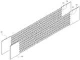
도 5는 본 발명에 따라 유로 채널 구획용 유로 격판 및 인쇄회로형 열교환판을 삽입하기 전에 2개의 측면판을 이격 배치한 사시도이다.
도 6은 본 발명에 따라 측면판의 각 슬릿에 유로 격판 및 인쇄회로형 열교환판을 삽입하고 용접한 조립체의 사시도이다.
도 7은 도 6에 따른 조립체에서 슬릿이 형성되지 않은 측면판의 양 말단부를 절단한 조립체의 사시도이다.
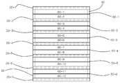
도 8은 도 7에 따른 조립체의 정면도이다.
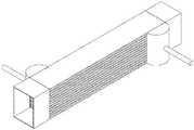
도 9는 도 7에 따른 조립체에 입출구용 매니폴드를 조립하기 전의 사시도이다.
도 10은 도 7에 따른 조립체에 입출구용 매니폴드를 조립하여 완성한 열교환 반응기의 사시도이다.
도 11은 입출구용 매니폴드의 사시도이다.1 is a perspective view illustrating a heat exchange fin structure usable in the present invention.
2 is a perspective view illustrating a printed circuit type heat exchange plate usable in the present invention.
3 is a perspective view illustrating another printed circuit type heat exchange plate usable in the present invention.
4 is a plan view of a side plate having a plurality of slits according to the present invention.
FIG. 5 is a perspective view of two channel plates disposed apart from each other before inserting the flow channel partitioning flow path plate and the printed circuit type heat exchange plate according to the present invention.
6 is a perspective view of an assembly in which a flow path plate and a printed circuit type heat exchange plate are inserted and welded to each slit of a side plate according to the present invention.
FIG. 7 is a perspective view of an assembly in which both ends of a side plate without a slit are cut in the assembly according to FIG. 6;
Figure 8 is a front view of the assembly according to Figure 7;
FIG. 9 is a perspective view of the assembly according to FIG. 7 before the inlet / outlet manifold is assembled.
10 is a perspective view of a heat exchange reactor completed by assembling an inlet / outlet manifold to the assembly according to FIG.
11 is a perspective view of the inlet / outlet manifold.
이하, 본 발명을 첨부된 도면을 참조하여 상세하게 설명한다.Hereinafter, the present invention will be described in detail with reference to the accompanying drawings.
도 1은 본 발명에서 사용 가능한 열교환핀 구조체(10)를 예시한 사시도로서, 열교환핀 구조체(10)는 열교환핀으로 삽입되는 금속 구조체이다. 열교환핀 구조체(10)는 도시된 바와 같이, 산과 골이 반복적으로 연결되는 형상을 가질 수 있다. 도면에서 상부와 하부가 직선 형태인 것이 예시되어 있는데, 지그재그 형상, 물결 형상, 주름 형상도 가능하다.1 is a perspective view illustrating a heat
열교환핀 구조체(10)는 촉매가 코팅 또는 담지된 반응용 열교환핀 구조체일 수 있다. 본 발명에서 사용되는 모든 열교환핀 구조체(10)는 반응용 열교환핀 구조체일 수 있다. 본 발명에서는 자체적으로 내부에 열교환 유로(22)를 포함하는 인쇄회로형 열교환판(20)을 사용하기 때문에, 별도의 열교환용 열교환핀 구조체를 사용할 필요가 없으며, 이에 따라 제작이 단순하고 용이해질 수 있다.The heat
열교환핀 구조체(10)는 유로 채널(60)에 삽입될 수 있는데, 반응기의 용접 조립 후에 반응용 유체 채널(60)을 삽입함으로써, 반응용 열교환핀 구조체의 열변형을 억제하거나 최소화할 수 있다. 또한, 촉매가 코팅 혹은 담지된 열교환핀 구조체를 반응기 용접 조립 후에 반응용 유로 채널(60)에 삽입 혹은 제거하는 것이 용이해질 수 있다.The heat
도 2는 본 발명에서 사용 가능한 인쇄회로형 열교환판(20)을 예시한 사시도로서, 인쇄회로형 열교환판(Printed Circuit Heat Exchange Plate)(20)은 자체적으로 내부에 적어도 하나의 이상의 열교환 유로(22)를 가질 수 있다. 열교환 유로(22)는 바람직하게는 복수 개로 형성될 수 있다. 각 열교환 유로(22)는 입구(24)와 출구(26)를 가질 수 있다.FIG. 2 is a perspective view illustrating a printed circuit type
인쇄회로형 열교환판(20)은 에칭이나 밀링 등의 가공을 통해 박판에 열교환 유로(22)를 형성한 후, 열교환 유로(22)가 형성된 박판에 확산접합 혹은 브레이징 등의 접합법을 이용하여 덮개판을 접합함으로써, 유로 입구(24)와 출구(26) 외에 기밀이 유지되는 1개의 판으로 구성될 수 있다.The printed circuit type
인쇄회로형 열교환판(20)의 두께는 바람직하게는 0.5 내지 5 mm, 더욱 바람직하게는 1 내지 3 mm일 수 있다.The thickness of the printed circuit type
인쇄회로형 열교환판(20)은 이 판의 외부에 흐르는 유체를 냉각 또는 가열하는 역할을 하며, 이를 위해 열교환 유로(22)에는 냉각수 등과 같은 냉매가 흐를 수 있고, 또한 열수나 온수와 같은 가열 매체가 흐를 수도 있다.The printed circuit type
도 3은 발명에서 사용 가능한 다른 인쇄회로형 열교환판을 예시한 사시도로서, 열교환 유로(20)의 패턴은 특별히 제한되지 않고, 예를 들어 직선형, 곡선형, 지그재그형 등 다양한 패턴이 가능하다. 열교환 유로(20)의 개수, 단면 형상, 직경, 간격 등도 특별히 제한되지 않고, 필요에 따라 적절하게 설정할 수 있다.3 is a perspective view illustrating another printed circuit type heat exchange plate that can be used in the invention. The pattern of the heat
도 4는 본 발명에 따라 복수의 슬릿(32, 34, 42, 44)이 형성된 측면판(30, 40)의 평면도로서, 측면판(30, 40)은 긴 직사각형의 금속 박판으로 구성될 수 있다. 측면판(30, 40)의 두께는 바람직하게는 0.5 내지 5 mm, 더욱 바람직하게는 1 내지 3 mm일 수 있다.4 is a plan view of
측면판(30, 40)에는 길이방향을 따라 복수의 슬릿(32, 34, 42, 44)이 형성될 수 있다. 본 발명은 측면판(30, 40)에 슬릿(32, 34, 42, 44)을 형성함으로써, 종래기술에 비해 열교환 반응기의 제작이 용이하고 부품 및 단가를 절감할 수 있다. 즉, 본 발명에서는 복수의 측면봉을 사용하지 않고, 슬릿(32, 34, 42, 44)이 형성된 단일 부품으로 열교환 반응기의 측면 벽을 구성할 수 있으므로, 반응기 제작이 용이하고 단가 저감이 가능하다.A plurality of
바람직하게는, 각 슬릿(32, 34, 42, 44)은 서로 평행하게 형성될 수 있다. 슬릿(32, 34, 42, 44)은 측면판(30, 40)의 양 말단부를 제외하고 형성될 수 있는데, 예를 들어 슬릿(32, 34, 42, 44)은 측면판(30, 40)의 길이방향 양 말단에서 바람직하게는 3 내지 15 mm, 더욱 바람직하게는 5 내지 10 mm를 제외하고 형성될 수 있다. 즉, 도면에 도시된 바와 같이, 슬릿(32, 34, 42, 44)이 가공되지 않은 부분의 길이는 각각 5 내지 10 mm일 수 있다. 따라서, 슬릿(32, 34, 42, 44)은 측면판(30, 40) 전체 길이의 일부로 형성될 수 있다.Preferably, each slit 32, 34, 42, 44 may be formed parallel to each other. The
슬릿(32, 34, 42, 44)에는 인쇄회로형 열교환판(20) 및 유로 격판(50)이 삽입될 수 있다. 즉, 슬릿(32, 34, 42, 44)은 유로 격판 삽입용 슬릿(32, 42) 및 인쇄회로형 열교환판 삽입용 슬릿(34, 44)으로 구분될 수 있다. 바람직하게는, 유로 격판 삽입용 슬릿(32, 42) 및 인쇄회로형 열교환판 삽입용 슬릿(34, 44)은 교대로 배치될 수 있다. 유로 격판 삽입용 슬릿(32, 42)의 길이 및 두께는 유로 격판(50)의 길이 및 두께와 거의 동일할 수 있고, 마찬가지로, 인쇄회로형 열교환판 삽입용 슬릿(34, 44)의 길이 및 두께는 인쇄회로형 열교환판(20)의 길이 및 두께와 거의 동일할 수 있다.The printed circuit type
슬릿(32, 34, 42, 44)은 유로 채널(60)보다 1개 적은 개수로 형성될 수 있다. 즉, 슬릿(32, 34, 42, 44)의 개수는 (총 유로채널 개수) -1개일 수 있다.The
또한, 측면판(30, 40)의 상단 및 하단에는 각각 단차를 이룬 긴 홈이 형성될 수 있다. 이 홈은 인쇄회로형 열교환판(20)을 수용하기 위한 것으로, 홈의 길이 및 두께는 인쇄회로형 열교환판(20)의 길이 및 두께와 거의 동일할 수 있다. 이와 같이, 두 측면판(30, 40)의 상단과 하단을 각각 연결하도록 인쇄회로형 열교환판(20)으로 마감하여 인쇄회로형 열교환판(20)을 열교환 반응기의 상면판과 하면판으로도 구성할 수 있다.Further, the upper and lower ends of the
도 5는 본 발명에 따라 유로 채널 구획용 인쇄회로형 열교환판(20) 및 유로 격판(50)을 삽입하기 전에 2개의 측면판(30, 40)을 이격 배치한 사시도로서, 길이방향을 따라 평행하게 형성되는 복수의 슬릿(32, 34, 42, 44)을 구비하는 측면판(30, 40)을 준비한 후, 2개의 측면판(30, 40)을 수직방향으로 세워서 서로 마주보도록 이격 배치한다. 측면판(30, 40)의 배치 간격은 측면판(30, 40) 사이의 거리 및 측면판(30, 40)의 두께를 포함하는 것으로 정의될 수 있다.5 is a perspective view of the two
도 6은 본 발명에 따라 측면판(30, 40)의 각 슬릿(32, 34, 42, 44)에 인쇄회로형 열교환판(20) 및 유로 격판(50)을 삽입하고 용접한 조립체의 사시도로서, 두 측면판(30, 40)의 각 슬릿(32, 34, 42, 44)에 복수의 유로 인쇄회로형 열교환판(20) 및 유로 격판(50)을 수평방향으로 평행하게 끼워 복수의 유로 채널(60)을 형성한 후, 측면판(30, 40)과 인쇄회로형 열교환판(20) 및 유로 격판(50)을 접합한다. 인쇄회로형 열교환판(20) 및 유로 격판(50)의 삽입 및 접합은 순차적으로 진행될 수 있다. 접합은 예를 들어 레이저 용접에 의해 수행될 수 있다. 이와 같이, 반응기를 구성하는 측면판 부재(30, 40)에 내부 유로 채널(60) 공간을 분리하는 인쇄회로형 열교환판(20) 및 유로 격판(50)의 개수만큼 슬릿(32, 34, 42, 44)을 형성하고, 형성된 양측 측면판(30, 40)의 슬릿(32, 34, 42, 44)에 인쇄회로형 열교환판(20) 및 유로 격판(50)을 삽입한 상태로 용접 가공한다.6 is a perspective view of an assembly in which a printed circuit type
유로 격판(50)은 긴 직사각형의 금속판일 수 있다. 유로 격판(50)은 유로 격판 삽입용 슬릿(32, 42)과 대응되는 길이 및 두께를 가질 수 있다. 유로 격판(50)의 두께는 바람직하게는 0.05 내지 2 mm, 더욱 바람직하게는 0.1 내지 0.5 mm일 수 있다.The flow
인쇄회로형 열교환판(20) 및 유로 격판(50)에 의해 슬릿(32, 34, 42, 44) 개수보다 한 개 많은 유로 채널(60)이 형성될 수 있다. 즉, 인쇄회로형 열교환판(20) 및 유로 격판(50)에 의해 슬릿(32, 34, 42, 44) 개수 +1개의 유로 채널(60)이 형성될 수 있다.One
본 발명에서 모든 유로 채널(60)은 반응용 유로 채널일 수 있다. 상술한 바와 같이, 인쇄회로형 열교환판(20)이 자체적으로 열교환 기능을 이미 갖고 있기 때문에, 열교환용 유로 채널을 별도로 마련할 필요 없이, 모든 유로 채널(60)을 반응용 유로 채널로 구성할 수 있다.In the present invention, all of the
용접을 진행하면서 이미 3차원 유로 채널(60)이 형성되는데, 유로 채널(60)의 형상 및 간격(높이)을 유지 및 지지하기 위해 유로 채널(60)의 높이(두께)와 유사한 삽입물을 설치하고 용접을 진행할 수 있다. 이때 삽입물은 채널에 탈부착이 가능한 열교환핀 구조체 혹은 굴곡이 있는 금속판을 사용할 수 있다.The three-
도 7은 도 6에 따른 조립체에서 슬릿(32, 34, 42, 44)이 형성되지 않은 측면판(30, 40)의 양 말단부를 절단한 조립체의 사시도로서, 측면판(30, 40)과 인쇄회로형 열교환판(20) 및 유로 격판(50)을 접합한 후, 슬릿(32, 34, 42, 44)이 형성되지 않은 두 측면판(30, 40)의 양 말단부를 절단하면, 입구와 출구 유로가 형성되면서 본 발명에 따른 열교환 반응기의 본체가 완성된다. 열교환 반응기의 일 측면에는 인쇄회로형 열교환판(20)의 입구(24) 또는 출구(26)가 노출되고, 다른 측면에는 인쇄회로형 열교환판(20)의 출구(26) 또는 입구(24)가 노출될 수 있다.7 is a perspective view of an assembly in which both ends of the
도 8은 도 7에 따른 조립체의 정면도로서, 총 5개의 인쇄회로형 열교환판(20-2 내지 20-6) 및 총 6개의 유로 격벽(50-1 내지 50-6)이 측면판(30, 40)의 총 11개의 슬릿(32, 34, 42, 44)에 삽입되어 총 12개의 유로 채널(60-1 내지 60-12)을 형성하고 있다. 유로 채널(60)의 수는 특별히 제한되지 않으며, 필요에 따라 적절하게 변경할 수 있다. 도면에서 점선으로 표시한 부분은 인쇄회로형 열교환판(20)의 내부에 형성된 열교환 유로(22)를 나타낸다.Fig. 8 is a front view of the assembly according to Fig. 7, in which a total of five printed circuit type heat exchange plates 20-2 to 20-6 and a total of six passage barrier ribs 50-1 to 50-6 are provided on
최상부의 인쇄회로형 열교환판(20-1) 및 최하부의 인쇄회로형 열교환판(20-7)은 슬릿(32, 34, 42, 44)이 아니라 측면판(30, 40)의 상단과 하단에 형성된 홈에 삽입되며, 각각 열교환 반응기의 상면판과 하면판으로도 구성된 것이다. 인쇄회로형 열교환판(20)을 열교환 반응기의 상면판과 하면판으로도 구성함으로써, 별도의 상면판과 하면판도 필요가 없다.The uppermost printed circuit type heat exchange plate 20-1 and the lowermost printed circuit type heat exchange plate 20-7 are not located at the
이와 같이, 인쇄회로형 열교환판(20)을 유로 격판으로 사용하면, 인접한 반응용 유로 채널(60)간의 구획을 나눌 수 있다. 또한 다중의 반응용 유로 채널(60)을 형성하기 위해, 인쇄회로형 열교환판(20)보다 두께가 얇은 유로 격판(50)을 사용하면, 하나의 인쇄회로형 열교환판(20)과 다음 인쇄회로형 열교환판(20) 사이에 복수 개의 층을 가진 유로 채널(60) 구획을 형성할 수 있다.As described above, when the printed circuit type
본 발명과 달리, 동일한 두께의 슬릿을 형성하고 유로 격판만을 사용하는 경우에는, 반응용 유로 채널과 열교환용 유로 채널의 유체가 혼합되지 않도록, 유로 채널들의 양 끝에 빗 모양의 막음판을 구성해야 하나, 본 발명에서는 자체적으로 열교환 유로(22)를 포함하는 인쇄회로형 열교환판(20)을 사용함에 따라 막음판이 필요 없으며, 이에 따라 제작이 용이해질 수 있다.Unlike the present invention, when a slit having the same thickness is used and only the flow path diaphragm is used, a comb-like plate should be formed at both ends of the flow channel so that the fluid of the reaction flow channel and the heat exchange flow channel is not mixed In the present invention, the use of the printed circuit type
또한, 다중의 반응용 유로 채널(60)간의 격벽을 0.3 내지 0.5 mm 정도의 판으로 구성하더라도, 자체의 열교환 유로(22)를 가진 인쇄회로형 열교환판(20)이 2±1 mm 정도의 두께를 가지므로, 슬릿 고정용 용접작업을 하더라도, 다소 두꺼운 판재를 사용하는 것이므로 열 변형이 적을 수 있다. 유로 형성 시 열 변형이 적을 경우, 용접 작업 사이에 판재의 냉각 시간을 줄이면서 작업 가능하기 때문에, 반응기 제작 작업이 용이해질 수 있다.Even if the partition walls between the multiple
도 9는 도 7에 따른 조립체에 입출구용 매니폴드를 조립하기 전의 사시도이고, 도 10은 도 7에 따른 조립체에 입출구용 매니폴드를 조립하여 완성한 열교환 반응기의 사시도이며, 도 11은 입출구용 매니폴드의 사시도로서, 인쇄회로형 열교환판(20)의 입구(24) 및 출구(26)를 통해 냉각수와 같은 유체가 유입 및 유출될 수 있도록 반응기의 입구와 출구를 형성하는 제1매니폴드(70, 72)가 도 7에 따른 조립체의 양 측면에 각각 조립될 수 있고, 반응용 유로 채널(60)을 통해 반응용 유체가 유입 및 유출될 수 있도록 반응기의 입구와 출구를 형성하는 제2매니폴드(80, 82)가 도 7에 따른 조립체의 전면과 후면에 각각 조립될 수 있다. 매니폴드(70, 72, 80, 82)의 형상과 크기 등은 도면에 한정되지 않고, 필요에 따라 다양하게 변경할 수 있다.
FIG. 9 is a perspective view of the assembly shown in FIG. 7 before assembling the inlet / outlet manifold, FIG. 10 is a perspective view of the heat exchange reactor completed by assembling the inlet / outlet manifold to the assembly according to FIG. 7, A
10: 열교환핀 구조체
20: 인쇄회로형 열교환판
22: 열교환 유로
24: 입구
26: 출구
30, 40: 측면판
32, 42: 유로 격판 삽입용 슬릿
34, 44: 인쇄회로형 열교환판 삽입용 슬릿
50: 유로 격판
60: 유로 채널
70, 72, 80, 82: 입출구용 매니폴드10: Heat exchange fin structure
20: printed circuit type heat exchange plate
22: Heat exchange channel
24: Entrance
26: Exit
30, 40: side plate
32, 42: Slit for insertion of the flow path diaphragm
34, 44: Slit for inserting a printed circuit type heat exchange plate
50: flow channel plate
60: Euro channel
70, 72, 80, 82: inlet / outlet manifold
Claims (12)
Translated fromKorean2개의 측면판을 수직방향으로 마주보도록 이격 배치하는 단계;
두 측면판의 적어도 하나 이상의 슬릿에 유로 격판을 수평방향으로 평행하게 끼워 복수의 유로 채널을 형성하는 단계;
자체적으로 내부에 적어도 하나 이상의 열교환 유로를 포함하는 인쇄회로형 열교환판을, 두 측면판의 적어도 하나 이상의 슬릿에 수평방향으로 평행하게 끼워 복수의 유로 채널을 형성하는 단계; 및
측면판, 유로 격판 및 인쇄회로형 열교환판을 각각 접합하는 단계를 포함하며,
슬릿은 유로 격판 삽입용 슬릿 및 인쇄회로형 열교환판 삽입용 슬릿으로 구분되는 것을 특징으로 하는 열교환 반응기의 제조방법.
Preparing a side plate having a plurality of slits formed in parallel along the longitudinal direction;
Disposing the two side plates so as to face each other in the vertical direction;
Forming a plurality of flow channel channels by horizontally inserting the flow channel plates in at least one slit of the two side plates in parallel;
Forming a plurality of flow channel channels by horizontally inserting a printed circuit type heat exchange plate including at least one heat exchange channel therein in parallel in at least one slit of the two side plates; And
A side plate, a flow path plate, and a printed circuit type heat exchange plate,
Wherein the slit is divided into a slit for inserting the flow path plate and a slit for inserting the printed circuit type heat exchange plate.
두 측면판의 상단과 하단을 각각 연결하도록 인쇄회로형 열교환판으로 마감하여 인쇄회로형 열교환판을 열교환 반응기의 상면판과 하면판으로도 구성하는 것을 특징으로 하는 열교환 반응기의 제조방법.
The method according to claim 1,
Wherein the printed circuit type heat exchange plate is formed by a printed circuit type heat exchange plate so as to connect the upper and lower ends of the two side plates, respectively, to the upper plate and the lower plate of the heat exchange reactor.
유로 격판 및 인쇄회로형 열교환판을 교대로 배치하는 것을 특징으로 하는 열교환 반응기의 제조방법.
The method according to claim 1,
A flow path plate and a printed circuit type heat exchange plate are arranged alternately.
유로 격판 및 유로 격판 삽입용 슬릿의 두께는 0.1 내지 0.5 mm인 것을 특징으로 하는 열교환 반응기의 제조방법.
The method according to claim 1,
Wherein the thickness of the slits for inserting the flow path plate and the flow path plate is 0.1 to 0.5 mm.
인쇄회로형 열교환판 및 인쇄회로형 열교환판 삽입용 슬릿의 두께는 1 내지 3 mm인 것을 특징으로 하는 열교환 반응기의 제조방법.
The method according to claim 1,
Wherein the printed circuit type heat exchange plate and the printed circuit type heat exchange plate insertion slit have a thickness of 1 to 3 mm.
측면판의 두께는 1 내지 3 mm인 것을 특징으로 하는 열교환 반응기의 제조방법.
The method according to claim 1,
Wherein the thickness of the side plate is 1 to 3 mm.
슬릿은 측면판의 양 말단부를 제외하고 형성되는 것을 특징으로 하는 열교환 반응기의 제조방법.
The method according to claim 1,
Wherein the slit is formed except for both ends of the side plate.
측면판, 유로 격판 및 인쇄회로형 열교환판을 각각 접합한 후, 슬릿이 형성되지 않은 두 측면판의 양 말단부를 절단하는 단계를 추가로 포함하는 열교환 반응기의 제조방법.
9. The method of claim 8,
Further comprising the step of joining the side plates, the flow path plates, and the printed circuit type heat exchange plates, respectively, and then cutting both end portions of the two side plates on which the slits are not formed.
슬릿은 측면판의 길이방향 양 말단에서 5 내지 10 mm를 제외하고 형성되는 것을 특징으로 하는 열교환 반응기의 제조방법.
9. The method of claim 8,
Wherein the slit is formed except for 5 to 10 mm at both longitudinal ends of the side plate.
산과 골이 반복적으로 연결되는 형상을 갖는 열교환핀 구조체를 유로 채널에 탈착 가능하게 삽입하는 단계를 추가로 포함하는 열교환 반응기의 제조방법.
The method according to claim 1,
Further comprising the step of detachably inserting a heat exchange fin structure having a shape in which an acid and a bone are repeatedly connected to the flow channel.
열교환핀 구조체는 촉매가 코팅 또는 담지된 반응용 열교환핀 구조체인 것을 특징으로 하는 열교환 반응기의 제조방법.12. The method of claim 11,
Wherein the heat exchange fin structure is a heat exchange fin structure for a reaction in which a catalyst is coated or supported.
Priority Applications (2)
| Application Number | Priority Date | Filing Date | Title |
|---|---|---|---|
| KR1020140162493AKR101655889B1 (en) | 2014-11-20 | 2014-11-20 | Heat exchange reactor and method for producing the same |
| US14/568,283US9643288B2 (en) | 2014-11-20 | 2014-12-12 | Heat exchange reactor using thin plate provided with flow path therein and method of manufacturing the same |
Applications Claiming Priority (1)
| Application Number | Priority Date | Filing Date | Title |
|---|---|---|---|
| KR1020140162493AKR101655889B1 (en) | 2014-11-20 | 2014-11-20 | Heat exchange reactor and method for producing the same |
Publications (2)
| Publication Number | Publication Date |
|---|---|
| KR20160060837A KR20160060837A (en) | 2016-05-31 |
| KR101655889B1true KR101655889B1 (en) | 2016-09-09 |
Family
ID=56009292
Family Applications (1)
| Application Number | Title | Priority Date | Filing Date |
|---|---|---|---|
| KR1020140162493AActiveKR101655889B1 (en) | 2014-11-20 | 2014-11-20 | Heat exchange reactor and method for producing the same |
Country Status (2)
| Country | Link |
|---|---|
| US (1) | US9643288B2 (en) |
| KR (1) | KR101655889B1 (en) |
Families Citing this family (9)
| Publication number | Priority date | Publication date | Assignee | Title |
|---|---|---|---|---|
| JP6659374B2 (en)* | 2016-01-22 | 2020-03-04 | 株式会社神戸製鋼所 | Heat exchanger and heat exchange method |
| US9987508B2 (en)* | 2016-08-31 | 2018-06-05 | Emerson Process Management Regulator Technologies Tulsa, Llc | Hybrid composite flame cell |
| CN108151561B (en)* | 2017-12-11 | 2020-03-17 | 西安交通大学 | Printed circuit board type heat exchanger for heat exchange of three or four fluids |
| CN107966055B (en)* | 2017-12-22 | 2024-02-02 | 上海发电设备成套设计研究院有限责任公司 | High-pressure compact heat exchanger and working method thereof |
| CN108489155A (en)* | 2018-05-31 | 2018-09-04 | 上海朗旦制冷技术有限公司 | A kind of novel dividing wall type micro heat exchanger |
| CN109668458A (en)* | 2018-12-20 | 2019-04-23 | 中国航空工业集团公司金城南京机电液压工程研究中心 | A kind of rib of slab declines scale primary surface heat exchanger |
| EP4024701A4 (en)* | 2019-08-26 | 2023-10-04 | Won Dae Ryu | Thermal collector and manufacturing method therefor |
| KR102400434B1 (en)* | 2019-08-26 | 2022-05-20 | 유원대 | Thermal collector and method for manufacturing thereof |
| CN113048819B (en)* | 2021-04-26 | 2022-02-08 | 山东大学 | Supercritical CO2Spiral Z-shaped printed circuit board type heat exchanger core |
Citations (2)
| Publication number | Priority date | Publication date | Assignee | Title |
|---|---|---|---|---|
| JP2011126756A (en)* | 2009-12-21 | 2011-06-30 | National Institute Of Advanced Industrial Science & Technology | Intra-laminate heat exchange type reactor, and method for manufacturing the same |
| KR101303437B1 (en)* | 2011-12-30 | 2013-09-05 | 한국수력원자력 주식회사 | Heat exchanger for reactor |
Family Cites Families (5)
| Publication number | Priority date | Publication date | Assignee | Title |
|---|---|---|---|---|
| JP4473996B2 (en) | 1999-12-27 | 2010-06-02 | 住友精密工業株式会社 | Plate fin type heat exchanger for high temperature |
| DE202004018857U1 (en) | 2004-12-07 | 2005-02-24 | Abb Patent Gmbh | metal housing |
| US20070261837A1 (en) | 2005-12-01 | 2007-11-15 | Modine Manufacturing Company | Compact high temperature heat exchanger, such as a recuperator |
| US8851357B2 (en)* | 2007-02-07 | 2014-10-07 | The Boeing Company | Apparatus and method for removing weld flash |
| GB0918738D0 (en) | 2009-10-26 | 2009-12-09 | Compactgtl Plc | Reactor with channels |
- 2014
- 2014-11-20KRKR1020140162493Apatent/KR101655889B1/enactiveActive
- 2014-12-12USUS14/568,283patent/US9643288B2/enactiveActive
Patent Citations (2)
| Publication number | Priority date | Publication date | Assignee | Title |
|---|---|---|---|---|
| JP2011126756A (en)* | 2009-12-21 | 2011-06-30 | National Institute Of Advanced Industrial Science & Technology | Intra-laminate heat exchange type reactor, and method for manufacturing the same |
| KR101303437B1 (en)* | 2011-12-30 | 2013-09-05 | 한국수력원자력 주식회사 | Heat exchanger for reactor |
Also Published As
| Publication number | Publication date |
|---|---|
| KR20160060837A (en) | 2016-05-31 |
| US20160144467A1 (en) | 2016-05-26 |
| US9643288B2 (en) | 2017-05-09 |
Similar Documents
| Publication | Publication Date | Title |
|---|---|---|
| KR101655889B1 (en) | Heat exchange reactor and method for producing the same | |
| US6968892B1 (en) | Heat exchanger | |
| JP4880095B2 (en) | Heat exchanger | |
| CN109479385B (en) | Core of laminated radiator | |
| US20180045472A1 (en) | Heat exchanger device | |
| JP2006525485A (en) | Heat exchanger core | |
| JP2011071386A5 (en) | ||
| KR20200121102A (en) | Micro channel heat exchanger and heat exchanging device comprising it | |
| JP2006183945A (en) | Oil cooler | |
| WO2014129176A1 (en) | Catalytic reactor and method for manufacturing catalytic reactor | |
| WO2005100896A1 (en) | Heat exchanger and method of producing the same | |
| JP5341549B2 (en) | heatsink | |
| JP2017106648A (en) | Heat exchanger | |
| JP6249611B2 (en) | Laminated structure | |
| JP5393606B2 (en) | Heat exchanger | |
| KR20090049989A (en) | Oil cooler | |
| KR101550245B1 (en) | Plate-type heat exchanger reactor and method for producing the same | |
| CN111386011A (en) | A lateral flow impingement microchannel cold plate and electronic equipment | |
| JP2009192140A (en) | Plate type heat exchanger | |
| CN100476336C (en) | Heat exchanger and method for manufacturing the same | |
| JP4774753B2 (en) | Heat exchanger and manufacturing method thereof | |
| JP2005233454A (en) | Heat exchanger | |
| JP2020088357A (en) | Heat exchanger | |
| JP2023068941A (en) | Heat exchanger and manufacturing method of heat exchanger | |
| JP2020200963A (en) | Heat exchange part of plate fin heat exchanger and method for manufacturing heat exchange system |
Legal Events
| Date | Code | Title | Description |
|---|---|---|---|
| A201 | Request for examination | ||
| PA0109 | Patent application | Patent event code:PA01091R01D Comment text:Patent Application Patent event date:20141120 | |
| PA0201 | Request for examination | ||
| E902 | Notification of reason for refusal | ||
| PE0902 | Notice of grounds for rejection | Comment text:Notification of reason for refusal Patent event date:20160218 Patent event code:PE09021S01D | |
| PG1501 | Laying open of application | ||
| E701 | Decision to grant or registration of patent right | ||
| PE0701 | Decision of registration | Patent event code:PE07011S01D Comment text:Decision to Grant Registration Patent event date:20160830 | |
| GRNT | Written decision to grant | ||
| PR0701 | Registration of establishment | Comment text:Registration of Establishment Patent event date:20160902 Patent event code:PR07011E01D | |
| PR1002 | Payment of registration fee | Payment date:20160905 End annual number:3 Start annual number:1 | |
| PG1601 | Publication of registration | ||
| PR1001 | Payment of annual fee | Payment date:20200609 Start annual number:5 End annual number:5 | |
| PR1001 | Payment of annual fee | Payment date:20240605 Start annual number:9 End annual number:9 | |
| PR1001 | Payment of annual fee | Payment date:20250610 Start annual number:10 End annual number:10 |