KR101655801B1 - Closing and opening device for refrigerator door - Google Patents
Closing and opening device for refrigerator doorDownload PDFInfo
- Publication number
- KR101655801B1 KR101655801B1KR1020140119165AKR20140119165AKR101655801B1KR 101655801 B1KR101655801 B1KR 101655801B1KR 1020140119165 AKR1020140119165 AKR 1020140119165AKR 20140119165 AKR20140119165 AKR 20140119165AKR 101655801 B1KR101655801 B1KR 101655801B1
- Authority
- KR
- South Korea
- Prior art keywords
- door
- main body
- rack
- gasket
- opening
- Prior art date
- Legal status (The legal status is an assumption and is not a legal conclusion. Google has not performed a legal analysis and makes no representation as to the accuracy of the status listed.)
- Active
Links
Images


Classifications
- E—FIXED CONSTRUCTIONS
- E05—LOCKS; KEYS; WINDOW OR DOOR FITTINGS; SAFES
- E05F—DEVICES FOR MOVING WINGS INTO OPEN OR CLOSED POSITION; CHECKS FOR WINGS; WING FITTINGS NOT OTHERWISE PROVIDED FOR, CONCERNED WITH THE FUNCTIONING OF THE WING
- E05F15/00—Power-operated mechanisms for wings
- E05F15/60—Power-operated mechanisms for wings using electrical actuators
- E05F15/603—Power-operated mechanisms for wings using electrical actuators using rotary electromotors
- E05F15/611—Power-operated mechanisms for wings using electrical actuators using rotary electromotors for swinging wings
- E05F15/614—Power-operated mechanisms for wings using electrical actuators using rotary electromotors for swinging wings operated by meshing gear wheels, one of which being mounted at the wing pivot axis; operated by a motor acting directly on the wing pivot axis
- F—MECHANICAL ENGINEERING; LIGHTING; HEATING; WEAPONS; BLASTING
- F25—REFRIGERATION OR COOLING; COMBINED HEATING AND REFRIGERATION SYSTEMS; HEAT PUMP SYSTEMS; MANUFACTURE OR STORAGE OF ICE; LIQUEFACTION SOLIDIFICATION OF GASES
- F25D—REFRIGERATORS; COLD ROOMS; ICE-BOXES; COOLING OR FREEZING APPARATUS NOT OTHERWISE PROVIDED FOR
- F25D23/00—General constructional features
- F25D23/02—Doors; Covers
- F25D23/028—Details
- E—FIXED CONSTRUCTIONS
- E05—LOCKS; KEYS; WINDOW OR DOOR FITTINGS; SAFES
- E05F—DEVICES FOR MOVING WINGS INTO OPEN OR CLOSED POSITION; CHECKS FOR WINGS; WING FITTINGS NOT OTHERWISE PROVIDED FOR, CONCERNED WITH THE FUNCTIONING OF THE WING
- E05F15/00—Power-operated mechanisms for wings
- E05F15/60—Power-operated mechanisms for wings using electrical actuators
- E05F15/603—Power-operated mechanisms for wings using electrical actuators using rotary electromotors
- E05F15/611—Power-operated mechanisms for wings using electrical actuators using rotary electromotors for swinging wings
- E05F15/616—Power-operated mechanisms for wings using electrical actuators using rotary electromotors for swinging wings operated by push-pull mechanisms
- E05F15/619—Power-operated mechanisms for wings using electrical actuators using rotary electromotors for swinging wings operated by push-pull mechanisms using flexible or rigid rack-and-pinion arrangements
- E—FIXED CONSTRUCTIONS
- E05—LOCKS; KEYS; WINDOW OR DOOR FITTINGS; SAFES
- E05F—DEVICES FOR MOVING WINGS INTO OPEN OR CLOSED POSITION; CHECKS FOR WINGS; WING FITTINGS NOT OTHERWISE PROVIDED FOR, CONCERNED WITH THE FUNCTIONING OF THE WING
- E05F15/00—Power-operated mechanisms for wings
- E05F15/70—Power-operated mechanisms for wings with automatic actuation
- E05F15/73—Power-operated mechanisms for wings with automatic actuation responsive to movement or presence of persons or objects
- E05F15/75—Power-operated mechanisms for wings with automatic actuation responsive to movement or presence of persons or objects responsive to the weight or other physical contact of a person or object
- E—FIXED CONSTRUCTIONS
- E06—DOORS, WINDOWS, SHUTTERS, OR ROLLER BLINDS IN GENERAL; LADDERS
- E06B—FIXED OR MOVABLE CLOSURES FOR OPENINGS IN BUILDINGS, VEHICLES, FENCES OR LIKE ENCLOSURES IN GENERAL, e.g. DOORS, WINDOWS, BLINDS, GATES
- E06B5/00—Doors, windows, or like closures for special purposes; Border constructions therefor
- E—FIXED CONSTRUCTIONS
- E06—DOORS, WINDOWS, SHUTTERS, OR ROLLER BLINDS IN GENERAL; LADDERS
- E06B—FIXED OR MOVABLE CLOSURES FOR OPENINGS IN BUILDINGS, VEHICLES, FENCES OR LIKE ENCLOSURES IN GENERAL, e.g. DOORS, WINDOWS, BLINDS, GATES
- E06B7/00—Special arrangements or measures in connection with doors or windows
- E06B7/16—Sealing arrangements on wings or parts co-operating with the wings
- E06B7/18—Sealing arrangements on wings or parts co-operating with the wings by means of movable edgings, e.g. draught sealings additionally used for bolting, e.g. by spring force or with operating lever
- E06B7/20—Sealing arrangements on wings or parts co-operating with the wings by means of movable edgings, e.g. draught sealings additionally used for bolting, e.g. by spring force or with operating lever automatically withdrawn when the wing is opened, e.g. by means of magnetic attraction, a pin or an inclined surface, especially for sills
- E06B7/215—Sealing arrangements on wings or parts co-operating with the wings by means of movable edgings, e.g. draught sealings additionally used for bolting, e.g. by spring force or with operating lever automatically withdrawn when the wing is opened, e.g. by means of magnetic attraction, a pin or an inclined surface, especially for sills with sealing strip being moved to a retracted position by elastic means, e.g. springs
- F—MECHANICAL ENGINEERING; LIGHTING; HEATING; WEAPONS; BLASTING
- F25—REFRIGERATION OR COOLING; COMBINED HEATING AND REFRIGERATION SYSTEMS; HEAT PUMP SYSTEMS; MANUFACTURE OR STORAGE OF ICE; LIQUEFACTION SOLIDIFICATION OF GASES
- F25D—REFRIGERATORS; COLD ROOMS; ICE-BOXES; COOLING OR FREEZING APPARATUS NOT OTHERWISE PROVIDED FOR
- F25D29/00—Arrangement or mounting of control or safety devices
- F25D29/003—Arrangement or mounting of control or safety devices for movable devices
- E—FIXED CONSTRUCTIONS
- E05—LOCKS; KEYS; WINDOW OR DOOR FITTINGS; SAFES
- E05Y—INDEXING SCHEME ASSOCIATED WITH SUBCLASSES E05D AND E05F, RELATING TO CONSTRUCTION ELEMENTS, ELECTRIC CONTROL, POWER SUPPLY, POWER SIGNAL OR TRANSMISSION, USER INTERFACES, MOUNTING OR COUPLING, DETAILS, ACCESSORIES, AUXILIARY OPERATIONS NOT OTHERWISE PROVIDED FOR, APPLICATION THEREOF
- E05Y2201/00—Constructional elements; Accessories therefor
- E05Y2201/40—Motors; Magnets; Springs; Weights; Accessories therefor
- E05Y2201/404—Function thereof
- E05Y2201/422—Function thereof for opening
- E05Y2201/426—Function thereof for opening for the initial opening movement
- E—FIXED CONSTRUCTIONS
- E05—LOCKS; KEYS; WINDOW OR DOOR FITTINGS; SAFES
- E05Y—INDEXING SCHEME ASSOCIATED WITH SUBCLASSES E05D AND E05F, RELATING TO CONSTRUCTION ELEMENTS, ELECTRIC CONTROL, POWER SUPPLY, POWER SIGNAL OR TRANSMISSION, USER INTERFACES, MOUNTING OR COUPLING, DETAILS, ACCESSORIES, AUXILIARY OPERATIONS NOT OTHERWISE PROVIDED FOR, APPLICATION THEREOF
- E05Y2201/00—Constructional elements; Accessories therefor
- E05Y2201/40—Motors; Magnets; Springs; Weights; Accessories therefor
- E05Y2201/43—Motors
- E05Y2201/434—Electromotors; Details thereof
- E—FIXED CONSTRUCTIONS
- E05—LOCKS; KEYS; WINDOW OR DOOR FITTINGS; SAFES
- E05Y—INDEXING SCHEME ASSOCIATED WITH SUBCLASSES E05D AND E05F, RELATING TO CONSTRUCTION ELEMENTS, ELECTRIC CONTROL, POWER SUPPLY, POWER SIGNAL OR TRANSMISSION, USER INTERFACES, MOUNTING OR COUPLING, DETAILS, ACCESSORIES, AUXILIARY OPERATIONS NOT OTHERWISE PROVIDED FOR, APPLICATION THEREOF
- E05Y2201/00—Constructional elements; Accessories therefor
- E05Y2201/60—Suspension or transmission members; Accessories therefor
- E05Y2201/606—Accessories therefor
- E05Y2201/618—Transmission ratio variation
- E—FIXED CONSTRUCTIONS
- E05—LOCKS; KEYS; WINDOW OR DOOR FITTINGS; SAFES
- E05Y—INDEXING SCHEME ASSOCIATED WITH SUBCLASSES E05D AND E05F, RELATING TO CONSTRUCTION ELEMENTS, ELECTRIC CONTROL, POWER SUPPLY, POWER SIGNAL OR TRANSMISSION, USER INTERFACES, MOUNTING OR COUPLING, DETAILS, ACCESSORIES, AUXILIARY OPERATIONS NOT OTHERWISE PROVIDED FOR, APPLICATION THEREOF
- E05Y2201/00—Constructional elements; Accessories therefor
- E05Y2201/60—Suspension or transmission members; Accessories therefor
- E05Y2201/622—Suspension or transmission members elements
- E05Y2201/71—Toothed gearing
- E05Y2201/716—Pinions
- E—FIXED CONSTRUCTIONS
- E05—LOCKS; KEYS; WINDOW OR DOOR FITTINGS; SAFES
- E05Y—INDEXING SCHEME ASSOCIATED WITH SUBCLASSES E05D AND E05F, RELATING TO CONSTRUCTION ELEMENTS, ELECTRIC CONTROL, POWER SUPPLY, POWER SIGNAL OR TRANSMISSION, USER INTERFACES, MOUNTING OR COUPLING, DETAILS, ACCESSORIES, AUXILIARY OPERATIONS NOT OTHERWISE PROVIDED FOR, APPLICATION THEREOF
- E05Y2201/00—Constructional elements; Accessories therefor
- E05Y2201/60—Suspension or transmission members; Accessories therefor
- E05Y2201/622—Suspension or transmission members elements
- E05Y2201/71—Toothed gearing
- E05Y2201/722—Racks
- E—FIXED CONSTRUCTIONS
- E05—LOCKS; KEYS; WINDOW OR DOOR FITTINGS; SAFES
- E05Y—INDEXING SCHEME ASSOCIATED WITH SUBCLASSES E05D AND E05F, RELATING TO CONSTRUCTION ELEMENTS, ELECTRIC CONTROL, POWER SUPPLY, POWER SIGNAL OR TRANSMISSION, USER INTERFACES, MOUNTING OR COUPLING, DETAILS, ACCESSORIES, AUXILIARY OPERATIONS NOT OTHERWISE PROVIDED FOR, APPLICATION THEREOF
- E05Y2400/00—Electronic control; Electrical power; Power supply; Power or signal transmission; User interfaces
- E05Y2400/10—Electronic control
- E05Y2400/36—Speed control, detection or monitoring
- E—FIXED CONSTRUCTIONS
- E05—LOCKS; KEYS; WINDOW OR DOOR FITTINGS; SAFES
- E05Y—INDEXING SCHEME ASSOCIATED WITH SUBCLASSES E05D AND E05F, RELATING TO CONSTRUCTION ELEMENTS, ELECTRIC CONTROL, POWER SUPPLY, POWER SIGNAL OR TRANSMISSION, USER INTERFACES, MOUNTING OR COUPLING, DETAILS, ACCESSORIES, AUXILIARY OPERATIONS NOT OTHERWISE PROVIDED FOR, APPLICATION THEREOF
- E05Y2400/00—Electronic control; Electrical power; Power supply; Power or signal transmission; User interfaces
- E05Y2400/10—Electronic control
- E05Y2400/40—Control units therefor
- E—FIXED CONSTRUCTIONS
- E05—LOCKS; KEYS; WINDOW OR DOOR FITTINGS; SAFES
- E05Y—INDEXING SCHEME ASSOCIATED WITH SUBCLASSES E05D AND E05F, RELATING TO CONSTRUCTION ELEMENTS, ELECTRIC CONTROL, POWER SUPPLY, POWER SIGNAL OR TRANSMISSION, USER INTERFACES, MOUNTING OR COUPLING, DETAILS, ACCESSORIES, AUXILIARY OPERATIONS NOT OTHERWISE PROVIDED FOR, APPLICATION THEREOF
- E05Y2400/00—Electronic control; Electrical power; Power supply; Power or signal transmission; User interfaces
- E05Y2400/80—User interfaces
- E05Y2400/85—User input means
- E05Y2400/851—Voice
- E—FIXED CONSTRUCTIONS
- E05—LOCKS; KEYS; WINDOW OR DOOR FITTINGS; SAFES
- E05Y—INDEXING SCHEME ASSOCIATED WITH SUBCLASSES E05D AND E05F, RELATING TO CONSTRUCTION ELEMENTS, ELECTRIC CONTROL, POWER SUPPLY, POWER SIGNAL OR TRANSMISSION, USER INTERFACES, MOUNTING OR COUPLING, DETAILS, ACCESSORIES, AUXILIARY OPERATIONS NOT OTHERWISE PROVIDED FOR, APPLICATION THEREOF
- E05Y2900/00—Application of doors, windows, wings or fittings thereof
- E05Y2900/30—Application of doors, windows, wings or fittings thereof for domestic appliances
- E05Y2900/31—Application of doors, windows, wings or fittings thereof for domestic appliances for refrigerators
Landscapes
- Engineering & Computer Science (AREA)
- Chemical & Material Sciences (AREA)
- Combustion & Propulsion (AREA)
- Physics & Mathematics (AREA)
- Mechanical Engineering (AREA)
- Thermal Sciences (AREA)
- General Engineering & Computer Science (AREA)
- Civil Engineering (AREA)
- Structural Engineering (AREA)
- Refrigerator Housings (AREA)
Abstract
Translated fromKoreanDescription
Translated fromKorean본 발명은 냉장고 도어 개폐장치에 관한 것이다.The present invention relates to a refrigerator door opening / closing apparatus.
일반적으로 냉장고는 저장실의 내부로 공급되는 냉기에 의해 저장물이 장기간 신선한 상태로 보관될 수 있도록 하는 장치이다. 저장실의 내부에 공급되는 냉기는 냉매의 열교환 작용에 의해서 생성된다. 저장실의 내부로 공급된 냉기는 대류에 의해서 저장실 내부에 고르게 전달되어 음식물을 원하는 온도로 저장할 수 있도록 한다.Generally, a refrigerator is a device that allows storage of a stored product in a fresh state for a long time by the cold air supplied to the inside of the storage room. The cool air supplied to the inside of the storage chamber is generated by the heat exchange action of the refrigerant. The cold air supplied to the inside of the storage room is uniformly transferred to the inside of the storage room by the convection so that the food can be stored at a desired temperature.
냉장고는 외관을 형성하는 본체의 내부에 음식물의 수납이 가능하도록 전면이 개방된 형태의 저장실을 구비한다. 그리고, 저장실의 전면에는 저장실의 개폐를 위한 도어가 설치된다. 도어는 본체에 힌지 결합되고 회동하여 저장실을 개폐한다.The refrigerator has a storage room in which a front surface is opened so that food can be stored in the inside of a main body that forms an outer appearance. A door for opening and closing the storage compartment is provided on the front surface of the storage compartment. The door is hinged to the main body and rotates to open and close the storage compartment.
그리고, 본체와 도어 사이에는 본체의 냉기가 외부로 유출되는 것을 방지하고, 본체와 도어가 밀착되게 하기 위해 가스켓이 설치된다.A gasket is provided between the main body and the door to prevent the cool air of the main body from flowing out to the outside, and to make the main body and the door closely contact with each other.
가스켓은 밀폐력 향상일 위해, 자성을 가지는 것이 일반적이다.The gasket is generally made of magnetic material because of its improved sealing performance.
이때, 도어를 자동으로 열기 위해서는 도어를 회전시키는 힘 뿐만 아니라, 가스켓을 본체에서 분리시키는 힘이 필요하다. 이하에서는At this time, in order to automatically open the door, not only the force for rotating the door but also the force for separating the gasket from the body is required. Hereinafter,
종래에는, 도어의 힌지부에 모터를 연결하는 기술이 사용되었는데, 이 경우, 가스켓을 분리하는 힘과 도어를 회전하기 위한 힘의 차이가 커서 비 효율적으로 큰 액추에이터가 필요하게 되고, 냉장고에 필요한 공간이 커서 기존 냉장고 사이즈 및 단열을 동등 수준으로 유지 한 채 구성하기는 어려운 문제점이 존재한다.
Conventionally, a technique of connecting a motor to a hinge portion of a door has been used. In this case, a large actuator is required inefficiently because of a large difference between a force for separating the gasket and a force for rotating the door, There is a problem that it is difficult to construct the refrigerator while keeping the size and insulation of the existing refrigerator at the same level.
본 발명이 해결하고자 하는 과제는 저출력 및 소형 모터를 사용하여서 냉장고 도어를 개폐하게 하기 위함이다.SUMMARY OF THE INVENTION Accordingly, the present invention has been made in view of the above problems, and it is an object of the present invention to open and close a refrigerator door by using a low-output and small-sized motor.
상기 과제를 달성하기 위하여, 실시예에 따른 냉장고 도어 개폐장치는 저장실이 형성된 본체에 힌지부로 연결된 도어와, 상기 도어와 상기 본체 사이에 위치되어 상기 도어와 상기 본체 사이를 밀폐하는 가스켓과, 상기 도어를 상기 본체에서 개폐시키는 개폐유닛을 포함하고, 상기 개폐유닛은, 구동력을 생성하는 구동부와, 상기 구동부의 회전력을 전달받아 상기 본체를 밀어서 상기 가스켓을 상기 본체 또는 도어에서 분리시키는 가스켓분리기구와, 상기 구동부의 회전력을 전달받아 상기 도어를 회동시키는 도어회동기구를 포함하고, 상기 가스켓분리기구는 상기 힌지부의 힌지축에서 소정의 거리로 이격되어 배치되는 것을 특징으로 한다.
According to an aspect of the present invention, there is provided a refrigerator door opening and closing apparatus comprising: a door connected to a main body having a storage chamber formed therein by a hinge; a gasket positioned between the door and the main body to seal between the door and the main body; A gasket separating mechanism for separating the gasket from the main body or the door by pushing the main body by receiving the rotational force of the driving part; and a gasket separating mechanism for separating the gasket from the main body or the door, And a door rotating mechanism that rotates the door by receiving the rotational force of the driving unit. The gasket separating mechanism is spaced apart from the hinge axis of the hinge unit by a predetermined distance.
본 발명의 냉장고에 따르면 다음과 같은 효과가 하나 혹은 그 이상 있다.According to the refrigerator of the present invention, one or more of the following effects can be obtained.
실시예는, 가스켓을 분리하는 가스켓분리기구와, 가스켓이 분리된 후 도어를 회전시키는 도어회동기구를 사용하여서, 적은 힘으로 가스켓을 본체에서 분리할 수 있고, 빠른 속도로 도어를 개폐할 수 있는 이점을 가진다.In the embodiment, the gasket separating mechanism for separating the gasket and the door turning mechanism for rotating the door after the gasket is separated can be used to separate the gasket from the body with a small force, .
또한, 실시예는 하나의 구동원으로 가스켓분리기구와 도어회동기구를 작동하므로, 도어와 본체 사이의 공간에서 차지하는 부피가 적은 이점이 존재한다.Further, since the embodiment operates the gasket separating mechanism and the door turning mechanism with one driving source, there is a small volume occupying in the space between the door and the main body.
또한, 랙가이드, 힌지기어 및 회동랙의 가변기어의 형상에 의해 도어의 작동 구간에 따라, 도어에 가해지는 힘과 도어의 속도를 변형하여서, 부드럽고 자연스러우며 에너지 효율이 높은 도어의 모션을 구현하는 이점이 존재한다.Further, the shape of the rack guide, the hinge gear, and the variable gears of the pivoting racks deforms the force applied to the door and the speed of the door according to the operating range of the door to realize a smooth, natural and energy- There is an advantage.
또한, 실시예는 저출력 및 소형화된 모터를 구동부에 사용할 수 있는 이점이 존재한다.In addition, the embodiment has an advantage that a low-output and miniaturized motor can be used for the driving unit.
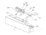
도 1은 본 발명의 제1 실시예 따른 냉장고를 도시한 사시도,
도 2는 도 1에 도시된 냉장고의 도어를 개방하였을 때의 정면도,
도 3은 본 발명의 제1 실시예 따른 냉장고 도어 개폐장치를 도시한 사시도,
도 4는 본 발명의 제1 실시예 따른 냉장고 도어 개폐장치를 도시한 분해 사시도,
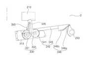
도 5는 본 발명의 제1 실시예 따른 개폐유닛의 사시도,
도 6은 본 발명의 제1 실시예 따른 개폐유닛의 평면도,
도 7은 본 발명의 제1 실시예 따른 개폐유닛의 일부에 대한 평면도,
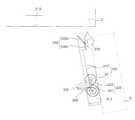
도 8 내지 도 10은 본 발명의 제1 실시예 따른 냉장고의 도어 개폐장치의 작동 모습을 도시한 도면,
도 11은 본 발명의 제2 실시예 따른 냉장고 도어 개폐장치의 제어블럭도,
도 12는 본 발명의 제3 실시예에 따른 냉장고 도어 개폐장치의 제어블럭도이다.1 is a perspective view illustrating a refrigerator according to a first embodiment of the present invention,
FIG. 2 is a front view of the refrigerator shown in FIG. 1 when the door is opened;
3 is a perspective view illustrating a refrigerator door opening and closing apparatus according to a first embodiment of the present invention.
4 is an exploded perspective view showing a refrigerator door opening / closing apparatus according to a first embodiment of the present invention,
5 is a perspective view of an opening / closing unit according to the first embodiment of the present invention,
6 is a plan view of the opening / closing unit according to the first embodiment of the present invention,
7 is a plan view of a part of the opening / closing unit according to the first embodiment of the present invention,
FIGS. 8 to 10 illustrate operation of a door opening and closing apparatus of a refrigerator according to a first embodiment of the present invention;
11 is a control block diagram of a refrigerator door opening and closing apparatus according to a second embodiment of the present invention,
12 is a control block diagram of a refrigerator door opening / closing apparatus according to a third embodiment of the present invention.
본 발명의 이점 및 특징, 그리고 그것들을 달성하는 방법은 첨부되는 도면과 함께 상세하게 후술되어 있는 실시예들을 참조하면 명확해질 것이다. 그러나 본 발명은 이하에서 게시되는 실시예들에 한정되는 것이 아니라 서로 다른 다양한 형태로 구현될 수 있으며, 단지 본 실시예들은 본 발명의 개시가 완전하도록 하고, 본 발명이 속하는 기술분야에서 통상의 지식을 가진 자에게 발명의 범주를 완전하게 알려주기 위해 제공되는 것이며, 본 발명은 청구항의 범주에 의해 정의될 뿐이다. 명세서 전체에 걸쳐 동일 참조 부호는 동일 구성 요소를 지칭한다.BRIEF DESCRIPTION OF THE DRAWINGS The advantages and features of the present invention, and the manner of achieving them, will be apparent from and elucidated with reference to the embodiments described hereinafter in conjunction with the accompanying drawings. The present invention may, however, be embodied in many different forms and should not be construed as limited to the embodiments set forth herein. Rather, these embodiments are provided so that this disclosure will be thorough and complete, and will fully convey the scope of the invention to those skilled in the art. To fully disclose the scope of the invention to those skilled in the art, and the invention is only defined by the scope of the claims. Like reference numerals refer to like elements throughout the specification.
다른 정의가 없다면, 본 명세서에서 사용되는 모든 용어(기술 및 과학적 용어를 포함)는 본 발명이 속하는 기술분야에서 통상의 지식을 가진 자에게 공통적으로 이해될 수 있는 의미로 사용될 수 있을 것이다. 또 일반적으로 사용되는 사전에 정의되어 있는 용어들은 명백하게 특별히 정의되어 있지 않은 한 이상적으로 또는 과도하게 해석되지 않는다.Unless defined otherwise, all terms (including technical and scientific terms) used herein may be used in a sense commonly understood by one of ordinary skill in the art to which this invention belongs. Also, commonly used predefined terms are not ideally or excessively interpreted unless explicitly defined otherwise.
도면에서 각 구성요소의 두께나 크기는 설명의 편의 및 명확성을 위하여 과장되거나 생략되거나 또는 개략적으로 도시되었다. 또한 각 구성요소의 크기와 면적은 실제크기나 면적을 전적으로 반영하는 것은 아니다.In the drawings, the thickness and the size of each component are exaggerated, omitted, or schematically shown for convenience and clarity of explanation. Also, the size and area of each component do not entirely reflect actual size or area.
또한, 실시예의 구조를 설명하는 과정에서 언급하는 각도와 방향은 도면에 기재된 것을 기준으로 한다. 명세서에서 실시예를 이루는 구조에 대한 설명에서, 각도에 대한 기준점과 위치관계를 명확히 언급하지 않은 경우, 관련 도면을 참조하도록 한다.Further, the angles and directions mentioned in the description of the structure of the embodiment are based on those shown in the drawings. In the description of the structures constituting the embodiments in the specification, reference points and positional relationships with respect to angles are not explicitly referred to, reference is made to the relevant drawings.
이하, 본 발명의 실시예들에 의하여 냉장고를 설명하기 위한 도면들을 참고하여 본 발명에 대해 설명하도록 한다.Hereinafter, the present invention will be described with reference to the drawings for explaining a refrigerator according to embodiments of the present invention.
도 1은 본 발명의 제1 실시예 따른 냉장고를 도시한 사시도, 도 2는 도 1에 도시된 냉장고의 도어를 개방하였을 때의 정면도이다.FIG. 1 is a perspective view of a refrigerator according to a first embodiment of the present invention, and FIG. 2 is a front view of the refrigerator shown in FIG. 1 when the door is opened.
본 실시예에 따른 냉장고는 도 1 및 도 2에 도시된 바와 같이, 저장실(F)(R)이 형성된 본체(2)와, 저장실(F)(R)을 냉각시키는 냉각 장치(40)와, 저장실(F)(R)을 여닫는 도어(4)(6)를 포함한다.1 and 2, the refrigerator according to the present embodiment includes a
냉각 장치(40)는 외부와 열교환하여서 저장실(F)(R)을 냉각시킨다. 냉각 장치(40)는 압축기와 응축기와 팽창기구와 증발기를 포함하는 냉동 사이클 장치로 이루어지는 것도 가능하고, 재질이 다르고 이격되게 배치된 제 1, 2 금속으로 전류를 인가하여 제 1 금속과 제 2 금속 중 하나가 흡열되고 다른 하나가 발열되게 하는 열전 소자로 이루어지는 것도 가능하며, 이하 냉동 사이클 장치로 이루어진 것으로 설명한다.The
냉각 장치(40)는 냉매는 압축기->응축기->팽창기구->증발기->압축기로 순환되면서 증발기를 냉각시킨다.The
냉각 장치(40)는 증발기가 저장실(F)(R) 외벽에 접촉되어 저장실(F)(R)을 직접 냉각시키는 것도 가능하고, 저장실(F)(R)의 공기를 증발기와 저장실(F)(R)로 순환시키는 냉기 순환팬(50)을 더 포함하여 저장실(F)(R) 내의 공기가 저장실(F)(R)과 증발기를 순환하면서 저장실(F)(R)을 냉각시킬 수도 있다.The
본체(2)의 저장실(F)(R)의 내부에는 음식재료나 반찬 등의 저장물이 올려지는 선반(8)(10)이 배치될 수 있다.The
또한, 본체(2)의 저장실(F)(R)의 내부에는 야채 및 과일이 저장되는 냉장고용 야채실이 설치될 수 있다.Inside the storage room F (R) of the
저장실(F)(R)은 본체(2)의 내부에 저장실 프레임(21)에 의해 형성될 수 있다. 저장실 프레임(21)은 도어(4)(6)가 접촉되는 영역을 제공하고, 저장실(F)(R)에 테두리를 형성하게 된다.The storage chamber F may be formed by a
저장실 프레임(21)은 도어(4)(6)의 배면과 밀착될 수 있도록 도어(4)(6)의 배면 둘레와 대응하도록 형성된다.The
즉, 저장실 프레임(21)의 내측면은 다단으로 단차지게 형성되며, 도어(4)(6)와 밀착될 수 있도록 형성된다.In other words, the inner surface of the
도어(4)(6)는 본체(2)에 좌우 방향과 상하 방향 중 한 방향으로 회전되게 배치되고, 도어(4)(6)를 닫았을 때 저장실(F)(R)을 향하는 면(즉, 배면)에 생수, 우유, 주스, 주류 등의 음료나 아이스크림 등의 빙과류 등이 보관되는 냉장고용 도어(4)(6) 바스켓(5)이 배치된다.The
냉장고용 도어(4)(6) 바스켓(5)은 도어(4)(6)에 상하 이격되게 복수개 설치되는 것이 바람직하다.It is preferable that a plurality of the baskets 5 are provided on the
저장실(F)(R)은 냉동실(F)과 냉장실(R)을 포함하고, 도어(4)(6)는 냉동실(F)을 여닫는 냉동실 도어(4)와, 냉장실(R)을 여닫는 냉장실 도어(6)를 포함하며, 선반(8)(10)은 냉동실(F)에 배치된 냉동실 선반(8)과, 냉장실(R)에 배치된 냉장실 선반(10)을 포함하고, 냉장고용 도어(4)(6) 바스켓(5)은 빙과류 등의 냉동물이 보관되는 냉동실에 설치될 수도 있고, 우유, 주스, 주류 등의 음료 등의 냉장물이 보관되는 냉장실에 설치될 수도 있다.The storage room F includes a freezing room F and a refrigerating compartment R. The
또한, 도어(4)(6)는 저장실(F)(R)을 개폐하도록 힌지부(23)에 의해 회동 가능하게 결합된다.The
도어(4)(6)의 형상과 크기는 적어도, 저장실(F)(R)을 차폐하는 크기와 형상을 가질 수 있다. 일예로, 저장실(F)(R)의 테두리를 형성하는 저장실 프레임(21)은 사각형으로 형성되고, 도어(4)(6)의 둘레가 저장실 프레임(21)과 접촉되도록 사각형으로 형성될 수 있다.The shape and size of the
도어(4)(6)의 배면에는 중앙에 저장물을 지지하는 도어(4)(6) 바스켓(5)이 위치되고, 도어(4)(6)와 본체(2)를 결합시키는 구속기구(미도시)가 더 형성될 수 있다.A door 5 is located at the rear of the
그리고, 도어(4)(6)의 개폐여부 및 개방각도를 감지하는 도어(4)(6) 스위치(22)가 형성될 수 있다.The door (4) and (6) switch (22) for sensing the opening and closing angles of the doors (4) and (6) can be formed.
또한, 도어(4)(6)와 도어(4)(6)와 본체(2) 사이에 위치되어 도어(4)(6)와 본체(2) 사이를 밀폐하는 가스켓(7)을 더 포함할 수 있다.It further includes a
가스켓(7)은 도어(4)(6)와 본체(2)의 사이에 위치되어 저장실(F)(R)을 밀폐한다.The
가스켓(7)은 저장실(F)(R)의 내부로 외기가 침투하는 것을 방지하기 위하여, 적어도 저장실(F)(R)을 감싸는 폐루프(Close-loop)를 형성할 수 있다.The
구체적으로, 가스켓(7)은 저장실(F)(R)의 테두리를 형성하는 저장실 프레임(21)과, 저장실 프레임(21)과 접촉되는 도어(4)(6)의 배면 사이에 위치될 수 있다. 또한, 가스켓(7)은 저장실 프레임(21) 또는 도어(4)(6)의 배면에 결합될 수 있다.Specifically, the
더욱 구체적으로, 가스켓(7)은 도어(4)(6) 배면의 둘레에 결합될 수 있다. 따라서, 가스켓(7)은 도어(4)(6)가 닫혔을 때 도어(4)(6)의 배면과 접하여 밀착되며, 저장실은 가스켓(7)에 의해 밀폐상태로 차폐될 수 있게 된다.More specifically, the
가스켓(7)은 자성을 가져서, 도어(4)(6) 또는 본체(2)와 접착력을 향상시키는 것이 보통이다.The
일반적으로, 도어(4)(6)를 자동으로 열기 위해서는 도어(4)(6)를 회전시키는 힘 뿐만 아니라, 가스켓(7)을 본체(2)에서 분리시키는 힘이 필요하다. 이하에서는, 가스켓(7)이 도어(4)(6)의 배면에 결합되는 것을 전제로 설명하도록 한다.Generally, in order to automatically open the
종래에는, 도어(4)(6)의 힌지부(23)에 모터를 연결하는 기술이 사용되었는데, 이 경우, 가스켓(7)을 분리하는 힘과 도어(4)(6)를 회전하기 위한 힘의 차이가 커서 비 효율적으로 큰 액추에이터가 필요하게 되고, 냉장고에 필요한 공간이 커서 기존 냉장고 사이즈 및 단열을 동등 수준으로 유지 한 채 구성하기는 어려운 문제점이 존재한다.Conventionally, a technique of connecting a motor to the
상술한 문제점을 해결하기 위해서, 실시예의 냉장고 도어 개폐장치를 안출하였다.In order to solve the above-described problems, a refrigerator door opening / closing device of the embodiment is disclosed.
이하, 냉장고 도어 개폐장치를 상술하도록 한다.Hereinafter, the refrigerator door opening / closing apparatus will be described in detail.
도 3은 본 발명의 제1 실시예 따른 냉장고 도어 개폐장치를 도시한 사시도, 도 4는 본 발명의 제1 실시예 따른 냉장고 도어 개폐장치를 도시한 분해 사시도, 도 5는 본 발명의 제1 실시예 따른 개폐유닛의 사시도, 도 6은 본 발명의 제1 실시예 따른 개폐유닛의 평면도, 도 7은 본 발명의 제1 실시예 따른 개폐유닛의 일부에 대한 평면도이다.FIG. 3 is an exploded perspective view of a refrigerator door opening / closing device according to a first embodiment of the present invention, FIG. 4 is an exploded perspective view illustrating a refrigerator door opening / closing device according to a first embodiment of the present invention, FIG. Fig. 6 is a plan view of an opening / closing unit according to the first embodiment of the present invention, and Fig. 7 is a plan view of a part of the opening and closing unit according to the first embodiment of the present invention.
본 발명의 제1 실시예 따른 냉장고 도어 개폐장치는 저장실이 형성된 본체(2)에 힌지부(23)로 연결된 도어(4)(6)와, 도어(4)(6)와 본체(2) 사이에 위치되어 도어(4)(6)와 본체(2) 사이를 밀폐하는 가스켓(7)과, 도어(4)(6)를 본체(2)에서 개폐시키는 개폐유닛(30)을 포함한다.The refrigerator door opening and closing apparatus according to the first embodiment of the present invention includes a
본체(2), 도어(4)(6), 가스켓(7)은 상술한 바와 같다.The
도 3 내지 도 7을 참고하면, 개폐유닛(30)은 도어(4)(6)를 본체(2)에서 개폐시킨다. 구체적으로, 도어(4)(6)의 개방작동 초기에는 가스켓(7)을 본체(2)에서 분리시키기 위해서, 큰 힘으로 도어(4)(6)와 본체(2)를 서로 이격시키고, 가스켓(7)에 본체(2)에서 분리된 후에는, 작은 힘으로 도어(4)(6)를 회전시킨다.3 to 7, the opening and
개폐유닛(30)은 도어(4)(6)에 결합되고, 도어(4)(6)와 본체(2) 사이의 공간에 위치될 수 있다. 구체적으로, 도어(4)(6)의 상단 또는 하단의 공간에 위치될 수 있다.The opening and
개폐유닛(30)은 도어(4)(6)에 케이싱에 의해 결합될 수 있다. 케이싱은 개폐유닛(30)을 도어(4)(6)에 고정하고 개폐유닛(30)의 각 구성품이 고정되는 공간을 제공한다.The opening and
예를 들면, 케이싱은 외관을 형성하고, 개폐유닛(30)이 위치되는 공간을 제공하는 제1케이싱(310)과, 제1케이싱(310)의 내부에 안착되고, 개폐유닛(30)이 고정되는 제2케이싱(313)을 포함할 수 있다.For example, the casing includes a
또한, 개폐유닛(30)은 가스켓(7)에 의해 정의되는 공간(폐루프의 내부)의 외부에 위치될 수 있다.Further, the opening /
예를 들면, 개폐유닛(30)은 구동부(320)와, 가스켓분리기구(330)와, 도어회동기구(340)를 포함할 수 있다.For example, the opening and
다른 예를 들면, 개폐유닛(30)은 구동부(320)와, 가스켓분리기구(330)와, 도어회동기구(340)와, 동기화부(350)를 포함할 수 있다.Alternatively, the opening and
구동부(320)는 구동력(회전력)을 생성하여 가스켓분리기구(330)와 도어회동기구(340)에 공급한다.The driving
예를 들면, 구동부(320)는 회전력을 발생시키는 모터(321)와 이를 전달하는 모터기어(322)를 포함할 수 있다.For example, the driving
구동부(320)는 직접적으로 가스켓분리기구(330)와 도어회동기구(340)에 연결될 수도 있고, 간접적으로 연결될 수 있다.The driving
구동부(320)는 다수의 연결기어를 통해 가스켓분리기구(330)와 도어회동기구(340)와 연결될 수 있다.The driving
구체적으로, 구동부(320)의 모터기어(322)는 제1연결기어(325a)에 치합되고, 제1연결기어(325a)는 제2연결기어(325b)에 치합되며, 제2연결기어(325b)는 제3연결기어(325c)에 치합된다.Specifically, the
제3연결기어(325c)에는 후술하는 가스켓분리기구(330)의 푸쉬 피니언 기어(331)가 치합될 수 있다. 다만, 이에 한정되는 것은 아니고, 하나의 모터(321)에서 가스켓분리기구(330)와 도어회동기구(340)에 전달되는 속도와 힘을 고려하여 설정될 수 있다.The third connecting
가스켓분리기구(330)는 구동부(320)의 회전력을 전달받아 본체(2)를 밀어서 가스켓(7)을 본체(2) 또는 도어(4)(6)에서 분리시킨다.The
특히, 가스켓분리기구(330)는 도어(4)(6)의 개방작동 초기에 가스켓(7)을 도어(4)(6) 또는 본체(2)에서 분리시키기 위해 큰 힘을 제공한다. 또한, 가스켓분리기구(330)는 도어(4)(6)의 개방작동 초기에 큰 힘을 제공하여서, 이 후에 도어회동기구(340)가 작은 힘으로 도어를 회전시키도록 한다.In particular, the
가스켓분리기구(330)는 구동부(320)와 큰 힘을 전달받도록 연결될 수 있다.The
예를 들면, 가스켓분리기구(330)는 구동부(320)의 회전력을 전달하는 푸쉬 피니언 기어(331)와, 푸쉬 피니언 기어(331)와 치합되어 본체(2)와 도어(4)(6) 사이의 거리를 증가시키는 푸쉬랙(333)을 포함할 수 있다.For example, the
즉, 가스켓분리기구(330)는 구동부(320)읠 회전력을 적선운동으로 전환하여서, 본체(2)에서 도어(4)(6)를 이격시킨다.That is, the
여기서, 푸쉬 피니언 기어(331)는 구동부(320)의 회전력을 푸쉬랙(333)으로 전달하게 된다.Here, the
구체적으로, 푸쉬 피니언 기어(331)는 제3연결기어(325c)와 치합되어서, 구동부(320)의 회전력을 전달받는다.Specifically, the
더욱 구체적으로, 푸쉬 피니언 기어(331)는 축을 공유하는 2개의 서브기어를 포함하여서, 도어회동기구(340)의 회동 피니언 기어(341)에 회전력을 전달할 수도 있다.More specifically, the
푸쉬랙(333)은 푸쉬 피니언 기어(331)의 회전력을 전달받아 적선 왕복운동 한다.The
푸쉬랙(333)은 푸쉬 피니언 기어(331)의 적은 회전수와 큰 힘을 전달받아 직선운동된다.The
푸쉬랙(333)은 도어(4)(6)의 배면에서 본체(2)의 전면 방향으로 직선운동된다. 따라서, 푸쉬랙(333)은 본체(2)를 밀어서 본체(2)와 도어(4)(6)를 이격거리를 증가시키고, 가스켓(7)을 본체(2)에서 분리시킨다.The
다만, 본체(2)의 전면은 도어(4)(6) 또는/및 가스켓(7)과 접촉을 위해 평평하게 형성된다. 그리고, 푸쉬랙(333)에 의해 도어(4)(6)와 본체(2)의 사이가 이격되면 도어(4)(6)는 힌지부(23)의 힌지축을 중심으로 회전되게 되게 된다. 푸쉬랙(333)이 본체(2) 방향으로 운동되면서, 도어(4)(6)가 회전되면, 푸쉬랙(333)과 본체(2)의 접점이 힌지부(23)에 멀어지게 되므로, 푸쉬랙(333)의 길이가 길어져야 도어(4)(6)의 회전속도를 유지할 수 있는 문제점이 존재한다.However, the front face of the
이를 해결하기 위해, 본체(2)의 전면에는 푸쉬랙(333)이 밀착되어 가이드되는 랙가이드(210)가 더 포함될 수 있다.In order to solve this problem, the
랙가이드(210)는 푸쉬랙(333)이 밀착되는 공간을 제공한다. 구체적으로, 랙가이드(210)는 힌지부(23)에서 멀어질 수록 도어(4)(6) 방향으로 돌출되는 형상의 커브를 가질 수 있다.The
구체적으로, 랙가이드(210)는 푸쉬랙(333)이 가이드되는 가이드홈(211)을 포함하고, 가이드홈(211)의 평면형상은 도 6에서 도시하는 바와 같이, 힌지부(23)에서 멀어질 수록 도어(4)(6) 방향으로 돌출되는 형상의 커브를 가질 수 있다.More specifically, the
따라서, 도어(4)(6)가 회전되더라도, 랙가이드(210)와 본체(2) 사이의 거리를 보완하여서, 도어(4)(6)의 초기 회전속도를 점진적으로 향상시킬 수 있다.Therefore, even if the
또한, 가스켓분리기구(330)는 힌지부(23)의 힌지축에서 소정의 거리로 이격되어 배치된다.Further, the
예를 들면, 가스켓분리기구(330)는, 힌지부(23)의 힌지축에서 힌지축과 수직한 방향(도어(4)(6) 손잡이 방향)으로 이격되어 배치될 수 있다.For example, the
구체적으로, 가스켓분리기구(330)의 푸쉬랙(333)은 힌지부(23)의 힌지축에서 힌지축과 수직한 방향(도어(4)(6) 손잡이 방향)으로 이격되어 배치될 수 있다.More specifically, the
여기서, 힌지축은 도어(4)(6)의 회전중심이 되는 가상의 축을 의미한다.Here, the hinge axis means a hypothetical axis which becomes the center of rotation of the
푸쉬랙(333)이 도어(4)(6)의 회전중심이 되는 힌지축에서 너무 가깝게 위치되면, 개방작동 초기에 가스켓(7)을 분리하는 데 너무 큰 힘이 요구되고, 푸쉬랙(333)이 도어(4)(6)의 힌지축에서 너무 멀게 위치되면, 개방작동 초기에 가스켓(7)을 분리하는 데 작은 힘이 요구되지만, 푸쉬랙(333)의 길이가 길어지게 되어서, 개폐유닛(30)의 부피가 증가하는 문제점이 있다.When the
따라서, 푸쉬랙(333)은 힌지축과의 이격거리는 도어(4)(6)의 폭의 30% 내지 60% 인 것이 바람직하다. 여기서, 도어(4)(6) 폭은 힌지축에 수직한 방향의 도어(4)(6) 길이를 의미할 것이다.Therefore, it is preferable that the
푸쉬랙(333)의 길이는 20mm 내지 40mm일 수 있다.The length of the
바람직하게는, 가스켓분리기구(330)는 도어(4)(6)를 본체(2) 전면에서, 3도 내지 5를 회전시킨다.Preferably, the
한편, 푸쉬랙(333)에는 후술하는 동기화부(350)에 걸림되는 제1보스(335)가 형성된다.On the other hand, the
아울러, 푸쉬랙(333)은 탄성체에 의해 초기 상태로 복원되는 탄성 복원력을 가질 수 있다.In addition, the
도어회동기구(340)는 구동부(320)의 회전력을 전달받아 도어(4)(6)를 회동시킨다.The door
도어회동기구(340)는 가스켓분리기구(330)에 의해 가스켓(7)이 본체(2) 또는 도어(4)(6)에서 분리된 후에 작동될 수 있다.The
도어회동기구(340)는, 가스켓분리기구(330)에 의해 가스켓(7)이 본체(2)에서 분리되어 큰 힘이 필요하지 않은 도어(4)(6)를 회전시킨다. 따라서, 도어회동기구(340)는 작은 힘으로 도어(4)(6)를 회전시킬 수 있다.The
도어회동기구(340)가 가스켓(7)이 본체(2)에서 분리된 후 작동되는 방법은 다양하다. 예를 들면, 이 방법은 물리적으로 동기화부(350)를 사용하거나, 다수의 구동원 사용하여서 가스켓분리기구(330)와 도어회동기구(340)를 별도로 제어할 수 있다.There are various ways in which the
예를 들면, 도어회동기구(340)는 구동부(320)의 회전력을 전달하는 회동 피니언 기어(341)와, 회동 피니언 기어(341)와 치합되어 직선운동하는 회동랙(343)을 포함한다.For example, the
여기서, 회동 피니언 기어(341)는 구동부(320)의 회전력을 회동랙(343)으로 전달하게 된다. 회동 피니언 기어(341)는 구동부(320)와 직접 또는 간접적으로 연결될 수 있다.Here, the
구체적으로, 회동 피니언 기어(341)는 푸쉬 피니언 기어(331)와 치합되어, 구동부(320)의 회전력을 전달받는다.Specifically, the
더욱 구체적으로, 회동 피니언 기어(341)는 축을 공유하는 2개의 서브기어를 포함하고, 2개의 서브기어 중 하나는 푸쉬 피니언 기어(331)에 치합되고, 다른 하나는 회동랙(343)에 치합된다.More specifically, the
회동랙(343)은 회동 피니언 기어(341)의 회전력을 전달받아 적선 왕복운동 한다. 구체적으로, 회동랙(343)은 회동랙(343)은 도어(4)(6)의 폭 방향으로 직선운동될 수 있다.The
회동랙(343)은 힌지부(23)의 외면에 형성된 힌지기어(233)에 치합된다.The
회동랙(343)은 도어의 개방동작 시에는 힌지부(23) 방향으로 이동되고, 도어의 폐쇄동작 시에는 그 반대방향으로 이동된다.The
예를 들면, 회동랙(343)은 바디(345)와, 바디(345)의 일단에 형성되어 회동 피니언 기어(341)와 치합되는 치합기어(347)와, 바디(345)의 타단에 형성되어 힌지기어(233)에 치합되어, 도어(4)(6)의 회전속도를 변화시키는 가속기어(346)를 포함할 수 있다.For example, the
치합기어(347)는 바디(345)의 길이방향을 따라 형성된다. 구체적으로, 치합기어(347)는 도어(4)(6)의 개방작동 초기에 회동 피니언 기어(341)와 이격되어 배치된다. 이후 외력에 의해 치합기어(347)는 회동 피니언 기어(341)에 치합될 수 있다.The engagement gear 347 is formed along the longitudinal direction of the
더욱 구체적으로, 바디(345)의 중앙 부분에 회동 피니언 기어(341)가 위치되고, 치합기어(347)는 바디(345)의 일단에서 바디(345)의 중앙 부분에 못 미치게 형성될 수 있다.More specifically, the
가속기어(346)는 힌지기어(233)에 치합되어 회동랙(343)의 직선운동력으로 도어(4)(6)를 회전시킨다. 힌지기어(233)는 고정되어 있으므로, 회동랙(343)이 운동되면 회동랙(343)이 고정된 도어(4)(6)가 상대운동된다.The
또한, 가속기어(346)는 도어(4)(6)의 회전속도를 변환시키는 구성을 가질 수 있다.Further, the accelerating
예를 들면, 가속기어(346)는 그 반경이 변화되는 힌지기어(233)와 치합되는 형상을 가질 수 있다.For example, the
구체적으로, 가속기어(346)는 제1기어 영역(346a)과, 제2기어 영역(346b)을 포함할 수 있다.Specifically, the accelerating
제1기어 영역(346a)은 회동랙(343)의 이동방향과 경사를 가지게 기어 이(Tooth)가 배치된다.A gear tooth is arranged so that the
제2기어 영역(346b)은 회동랙(343)의 이동방향과 평행하게 기어 이가 배치된다.The
제1기어 영역(346a)은 도어(4)(6)의 회전 초기에 큰 힘을 전달하게 된다.The
여기서, 힌지부(23)는 본체(2)에 고정되는 고정힌지(231)와, 도어(4)(6)에 고정되고 고정힌지(231)에 회동 가능하게 결합되는 회동힌지(232)를 포함할 수 있다.The
힌지부(23)는 도어(4)(6)의 폭 방향 일단에 위치된다.The
구체적으로, 힌지기어(233)는 고정힌지(231)의 외면에 형성되게 된다.Specifically, the
힌지기어(233)의 반경이 크게 되면, 도어(4)(6)를 회전시키기 위해서 작은 힘이 요구되지만, 도어(4)(6)의 회전속도는 느리게 되고, 힌지기어(233)의 반경이 작게 되면, 도어(4)(6)를 회전시키기 위해서 큰 힘이 요구되지만, 도어(4)(6)의 회전속도는 빠르게 된다.A small force is required to rotate the
도어(4)(6)는 회전 초기에는 큰 힘이 요구되지만, 일정 속도 이상에서는 작은 힘만 필요하게 된다.The doors (4) and (6) require a large force at the initial stage of rotation, but only a small force at a constant speed or more.
따라서, 힌지기어(233)는 도어(4)(6)의 회전속도 및 도어(4)(6)에 가해지는 힘을 변화시키는 형상을 가질 수 있다.Therefore, the
구체적으로, 힌지기어(233)의 반경은 도어(4)(6)가 오픈되는 회전방향으로 갈수록 줄어들 수 있다.Specifically, the radius of the
더욱 구체적으로, 힌지기어(233)는 제1반경(R1)에서 도어(4)(6)가 오픈되는 회전방향으로 갈수록 제2반경(R2)으로 점진적으로 줄어들 수 있다.More specifically, the
이 때, 반경이 큰 힌지기어(233)에는 제1기어 영역(346a)이 치합되고, 반경이 작은 힌지기어(233)에는 제2기어 영역(346b)이 치합되게 된다.At this time, the
또한, 도어(4)(6)의 개방작동 초기에, 회동랙(343)의 가속기어(346)는 힌지기어(233)의 반경이 가장 큰 위치에 치합된다. 구체적으로, 도어(4)(6)의 개방작동 초기에 제1기어 영역(346a)의 끝단은 반경이 가장 큰 힌지기어(233)에 치합되게 된다.The
물론, 부드러운 치합을 위해, 제1기어 영역(346a)은 곡률을 가질 수도 있다.Of course, for smooth engagement, the
동기화부(350)는 도어회동기구(340)가 가스켓분리기구(330)에 의해 가스켓(7)이 본체(2) 또는 도어(4)(6)에서 분리된 후에 작동되도록 한다. 즉, 동기화부(350)는 도어회동기구(340)가 가스켓분리기구(330)와 시간차를 가지고 작동되게 한다.The synchronizing
동기화부(350)는 도어회동기구(340)의 작동의 가스켓분리기구(330) 보다 지연되는 다양한 구성을 가질 수 있다.The
예를 들면, 도 7에서 도시하는 바와 같이, 동기화부(350)는 푸쉬랙(333)에 의해 회전되어 회동랙(343)을 회동 피니언 기어(341)에 치합시킬 수 있다.7, the
구체적으로, 동기화부(350)는 푸쉬랙(333)에 의해 회전되어 회동랙(343)을 힌지부(23) 방향으로 이동시켜서, 회동 피니언 기어(341)에 치합시킬 수 있다.Specifically, the
이 때, 회동 피니언 기어(341)가 회전되어 회동랙(343)을 힌지기어(233)에 치합시킬 수 있다.At this time, the
더욱 구체적으로, 동기화부(350)는 일단이 제1보스(335)에 걸림되고, 타단이 회동랙(343)에 형성된 제2보스(348)에 걸림되는 회전체(351)와 회전체(351)를 케이싱에 회동 가능하게 고정하는 고정핀(353)을 포함할 수 있다.More specifically, the synchronizing
회전체(351)는 제1보스(335)에 의해 고정핀(353)을 중심으로 회전되고, 제2보스(348)에 걸림되어 회동랙(343)을 이동시킨다.
The
이하, 냉장고 도어 개폐 장치의 작동에 대해 설명하도록 한다.Hereinafter, the operation of the refrigerator door opening / closing apparatus will be described.
도 8 내지 도 10은 본 발명의 제1 실시예 따른 냉장고의 도어개폐장치의 작동 모습을 도시한 도면이다.8 to 10 are views showing operation of a door opening / closing device of a refrigerator according to a first embodiment of the present invention.
도 8 내지 도 10에서는 도어(4)(6) 및 본체(2)를 생략하였다.8 to 10, the
먼저, 도어(4)(6)의 개방작동에 대해 설명하도록 한다.First, the opening operation of the doors (4) and (6) will be described.
도 8을 참조하면, 도어(4)(6)의 닫힘 상태를 도시하고 있다. 도어(4)(6)의 개방작동의 초기에는 회동랙(343)과 힌지기어(233)가 이격되어 있다.Referring to Fig. 8, the
도어(4)(6)의 개방작동이 시작되면, 구동부(320)의 모터(321)가 회전되고, 모터(321)의 회전력은 연결기어에 의해 푸쉬 피니언 기어(331)로 전달된다.When the opening operation of the
도 9를 참조하면, 푸쉬 피니언 기어(331)가 회전되어서, 푸쉬랙(333)을 도어(4)(6)의 전면에서 배면 방향으로 직선운동시킨다.9, the
푸쉬랙(333)과 본체(2)의 반발력에 의해 도어(4)(6)가 회전되기 시작한다.The
도어(4)(6)가 회전되기 시작되면, 본체(2)에 형성된 랙가이드(210)에 의해 본체(2)와 푸쉬랙(333) 사이의 거리가 보정된다.The distance between the
푸쉬랙(333)에 의해 가스켓(7)과 도어(4)(6) 또는 본체(2)가 분리된다.The
푸쉬랙(333)에 운동에 의해 동기화부(350)의 회전체(351)가 회전되고, 회전체(351)에 의해 회동랙(343)이 이동된다.The
그리고, 회동랙(343)은 회동 피니언 기어(341)와 치합되고, 회동 피니언 기어(341)의 회전에 의해 힌지기어(233) 방향으로 이동된다.The
이후, 회동랙(343)의 가속기어(346)가 힌지기어(233)와 치합된다.Thereafter, the
도 10을 참조하면, 회동랙(343)의 이동에 의해 도어(4)(6)가 회전되게 되어서, 도어(4)(6)가 개방된다.Referring to Fig. 10, by the movement of the
이 때, 가속기어(346)와 힌지기어(233) 형상에 의해 도어(4)(6)의 회전속도가 조절될 수 있다.At this time, the rotation speed of the doors (4) and (6) can be adjusted by the shape of the accelerator gear (346) and the hinge gear (233).
도어(4)(6)의 폐쇄작동은 도어(4)(6)의 개방작동의 역순과 같다.The closing operation of the doors (4) and (6) is the reverse of the opening operation of the doors (4) and (6).
도의 폐쇄작동은 구동부(320)의 모터(321)가 도어(4)(6)의 개방작동과 반대방향으로 회전하면서 시작된다.The closing operation of the door starts when the
이 때, 푸쉬랙(333)은 도어(4)(6)가 본체(2)와 접촉되는 과정에서 완충력을 제공하게 된다.
At this time, the
도 11은 본 발명의 제2 실시예 따른 냉장고 도어 개폐장치의 제어블럭도이다.11 is a control block diagram of a refrigerator door opening and closing apparatus according to a second embodiment of the present invention.
도 11을 참조하면, 제2 실시예에 따른 냉장고 도어 개폐장치는 제1 실시예와 비교하면, 입력부(360) 및 제어부(370)를 더 포함할 수 있다. 제2 실시예에서는 제1실시예와 중복되는 부분에 대한 설명은 생략하도록 한다.Referring to FIG. 11, the refrigerator door opening / closing apparatus according to the second embodiment may further include an
입력부(360)는 도어(4)(6)를 개폐하는 개폐명령을 입력 받는다.The
입력부(360)는 사용자가 도어(4)(6)의 동작 제어를 위하여 입력하는 입력 데이터를 발생시킨다. 입력부(360)에서 입력된 입력 데이터는 제어부(370)에 송신된다.The
입력부(360)는 사용자의 음성을 인식하여 사용자의 음성에 대응되는 도어(4)(6)의 개폐명령을 전기적 신호(입력 데이터)로 변환할 수 있다.The
또한, 입력부(360)는 사용자의 터치를 인식하여 사용자의 터치에 대응되는 도어(4)(6)의 개폐명령을 전기적 신호로 변환할 수 있다.Further, the
예를 들면, 입력부(360)는 키 패드(key pad), 돔 스위치(dome switch), 터치 패드(정압/정전), 조그 휠, 조그 스위치, 슬라이드 스위치, 핑거 마우스 등으로 구성될 수 있다.For example, the
제어부(370)는 입력부(360)에서 입력 받은 개폐명령을 바탕으로 개폐유닛(30)을 제어할 수 있다.The
제어부(370)는 구동부(320)의 모터(321)의 온/오프, 회전속도, 회전방향을 제어할 수 있다.The
구체적으로, 제어부(370)는 입력부(360)에 의해 도어(4)(6) 개방명령이 입력되는 경우, 구동부(320)의 모터(321)를 회전시켜서 도어(4)(6)를 개방한다. 또한, 제어부(370)는 입력부(360)에 의해 도어(4)(6) 폐쇄명령이 입력되는 경우, 구동부(320)의 모터(321)를 회전시켜서 도어(4)(6)를 개방하게 된다.The
또한, 제어부(370)는 도어(4)(6)의 회전 중에 모터(321)에 소정의 부하가 발생되는 경우, 도어(4)(6)에 장애물이 걸린 것으로 판단하고, 구동부(320)의 모터(321) 회전을 정지시킬 수도 있다.When a predetermined load is generated in the
도 12는 본 발명의 제3 실시예에 따른 냉장고 도어 개폐장치의 제어블럭도이다.12 is a control block diagram of a refrigerator door opening / closing apparatus according to a third embodiment of the present invention.
도 12를 참조하면, 제3실시예에 따른 냉장고 도어 개폐장치는 제2실시예와 비교하면, 도어스위치(22)와, 구동부(320)가 2개의 구동원을 가져서, 가스켓분리기구(330)와, 도어회동기구(340)가 별개의 구동원으로 작동되는 차이점이 존재한다.12, the refrigerator door opening and closing apparatus according to the third embodiment is different from the second embodiment in that the
도어스위치(22)는 도어(4)(6)가 본체(2)에서 일정각도로 오픈되는 것을 감지하고, 감지결과를 제어부(370)에 송신한다.The
도어스위치(22)는 도어(4)(6)의 오픈 여부를 감지할 수 있는 다양한 공지기술이 사용될 수 있다.Various known techniques for detecting whether the
구동부(320)는 가스켓분리기구(330)에 회전력을 제공하는 제1구동원(327)과, 도어회동기구(340)에 회전력을 제공하는 제2구동원(329)을 포함할 수 있다.The driving
제2실시예와 달리 제3실시예의 냉장고 도어 개폐장치는 가스켓분리기구(330)와 도어회동기구(340)가 푸쉬 피니언 기어(331)와 회동 피니언 기어(341)가 치합되어 회전력을 전달받는 것이 아니고, 별개의 구동원으로 작동된다.The refrigerator door opening / closing apparatus of the third embodiment differs from the second embodiment in that the
제1구동원(327)은 푸쉬 피니언 기어(331)에 회전력을 전달하고, 제2구동원(329)은 회동 피니언 기어(341)에 회전력을 전달하게 된다.The
따라서, 제3실시예에서는 제2실시예의 동기화부(350)가 생략 가능하다.Therefore, in the third embodiment, the
제어부(370)는 도어(4)(6)스위치에서 입력되는 신호를 바탕으로 제1구동원(327)과 제2구동원(329)을 시간차를 가지고 작동시킨다.The
구체적으로, 도어(4)(6) 개방작동 시에, 제어부(370)는 제1구동원(327)을 작동시켜 본체(2)에서 가스켓(7)을 분리 후에, 도어(4)(6)스위치에서 입력되는 신호를 바탕으로 제2구동원(329)을 작동시켜서 도어(4)(6)를 회전시킨다. 물론, 도어(4)(6) 폐쇄작동 시에는 개방작동의 역순으로 작동된다.
Specifically, when the
이상에서는 본 발명의 바람직한 실시예에 대하여 도시하고 설명하였지만, 본 발명은 상술한 특정의 실시예에 한정되지 아니하며, 특허청구범위에서 청구하는 본 발명의 요지를 벗어남이 없이 당해 발명이 속하는 기술분야에서 통상의 지식을 가진 자에 의해 다양한 변형실시가 가능한 것은 물론이고, 이러한 변형실시들은 본 발명의 기술적 사상이나 전망으로부터 개별적으로 이해되어서는 안될 것이다.
While the present invention has been particularly shown and described with reference to exemplary embodiments thereof, it is to be understood that the invention is not limited to the disclosed exemplary embodiments, but, on the contrary, It should be understood that various modifications may be made by those skilled in the art without departing from the spirit and scope of the present invention.
Claims (19)
Translated fromKorean상기 도어와 상기 본체 사이에 위치되어 상기 도어와 상기 본체 사이를 밀폐하는 가스켓과,
상기 도어를 상기 본체에서 개폐시키는 개폐유닛을 포함하고,
상기 개폐유닛은,
구동력을 생성하는 구동부와,
상기 구동부의 회전력을 전달받아 상기 본체를 밀어서 상기 가스켓을 상기 본체 또는 도어에서 분리시키는 가스켓분리기구와,
상기 구동부의 회전력을 전달받아 상기 도어를 회동시키는 도어회동기구를 포함하고,
상기 가스켓분리기구는 상기 힌지부의 힌지축에서 소정의 거리로 이격되어 배치되며,
상기 도어회동기구는,
상기 가스켓분리기구에 의해 상기 가스켓이 상기 본체 또는 도어에서 분리된 후에 작동되고,
상기 도어회동기구는,
상기 구동부의 회전력을 전달하는 회동 피니언 기어와,
상기 회동 피니언 기어와 치합되어 직선운동하는 회동랙을 포함하고,
상기 회동랙은 상기 힌지부의 외면에 형성된 힌지기어에 치합되는 냉장고 도어 개폐장치.A door connected to the main body having the storage chamber formed therein by a hinge,
A gasket positioned between the door and the main body to seal between the door and the main body,
And an opening / closing unit for opening / closing the door in the main body,
The opening /
A driving unit for generating a driving force,
A gasket separating mechanism for separating the gasket from the main body or the door by pushing the main body by receiving the rotational force of the driving part,
And a door rotating mechanism that receives the rotational force of the driving unit to rotate the door,
The gasket separating mechanism is disposed at a predetermined distance from the hinge axis of the hinge portion,
The door rotation mechanism includes:
The gasket is operated by the gasket separating mechanism after the gasket is separated from the main body or the door,
The door rotation mechanism includes:
A rotary pinion gear that transmits the rotational force of the driving unit,
And a pivoting rack engaged with the pivot pinion gear and linearly moving,
And the pivoting rack is engaged with a hinge gear formed on an outer surface of the hinge unit.
상기 가스켓분리기구는,
상기 구동부의 회전력을 전달하는 푸쉬 피니언 기어와,
상기 푸쉬 피니언 기어와 치합되어 상기 본체와 상기 도어 사이의 거리를 증가시키는 푸쉬랙을 포함하는 냉장고 도어 개폐장치.The method according to claim 1,
The gasket separating mechanism includes:
A push pinion gear for transmitting a rotational force of the driving portion,
And a push rack engaging with the push pinion gear to increase a distance between the main body and the door.
상기 푸쉬랙은,
상기 도어의 배면에서 상기 본체의 전면 방향으로 직선운동되는 냉장고 도어 개폐장치.3. The method of claim 2,
In the push rack,
Wherein the door is linearly moved from a rear surface of the door to a front direction of the main body.
상기 푸쉬랙은 상기 힌지축과의 이격거리는 상기 도어의 폭의 30% 내지 60% 인 냉장고 도어 개폐장치.The method of claim 3,
Wherein a distance between the push rack and the hinge shaft is 30% to 60% of the width of the door.
상기 본체의 전면에는 상기 푸쉬랙이 가이드되는 랙가이드를 더 포함하고,
상기 랙가이드는 상기 힌지부에서 멀어질 수록 상기 도어방향으로 돌출되는 형상을 가지는 냉장고 도어 개폐장치.The method of claim 3,
And a rack guide to which the push rack is guided,
Wherein the rack guide protrudes toward the door as the rack guide moves away from the hinge.
상기 도어가 상기 본체에서 일정각도로 오픈되는 것을 감지하는 도어스위치와,
상기 구동부는,
상기 가스켓분리기구에 회전력을 제공하는 제1구동원과,
상기 도어회동기구에 회전력을 제공하는 제2구동원을 포함하며,
상기 도어스위치에서 입력되는 신호를 바탕으로 제1구동원과 제2구동원을 시간차를 가지고 작동시키는 제어부를 포함하는 냉장고 도어 개폐장치.The method according to claim 1,
A door switch for detecting that the door is opened at a predetermined angle from the main body,
The driving unit includes:
A first driving source for providing rotational force to the gasket separating mechanism,
And a second driving source for providing rotational force to the door rotation mechanism,
And a controller for operating the first driving source and the second driving source with a time difference based on a signal input from the door switch.
상기 푸쉬랙에 의해 회전되어 상기 회동랙을 상기 회동 피니언 기어에 치합시키는 동기화부를 더 포함하는 냉장고 도어 개폐장치.3. The method of claim 2,
Further comprising a synchronizing portion that is rotated by the push rack to engage the rotating rack with the rotating pinion gear.
상기 회동랙은 상기 도어의 폭 방향으로 직선운동되고,
상기 동기화부는 상기 푸쉬랙에 의해 회전되어 상기 회동랙을 상기 힌지부 방향으로 이동시키는 냉장고 도어 개폐장치.10. The method of claim 9,
The pivoting rack is linearly moved in the width direction of the door,
Wherein the synchronizer is rotated by the push rack to move the rotating rack in the direction of the hinge portion.
상기 회동랙은,
바디,
상기 바디의 일단에 형성되어 회동 피니언 기어와 치합되는 치합기어와,
상기 바디의 타단에 형성되어 상기 힌지기어에 치합되어, 도어의 회전속도를 변화시키는 가속기어를 포함하는 냉장고 도어 개폐장치.The method according to claim 1,
The pivoting rack includes:
body,
A coupling gear formed at one end of the body and engaged with the rotation pinion gear,
And an accelerating gear formed at the other end of the body and engaged with the hinge gear to change the rotational speed of the door.
상기 가속기어는,
상기 회동랙의 이동방향과 경사를 가지는 제1기어 영역과,
상기 회동랙의 이동방향과 평행한 제2기어 영역을 포함하는 냉장고의 도어 개폐장치.12. The method of claim 11,
Wherein the accelerator
A first gear region having a moving direction and an inclination of the rotating rack,
And a second gear region that is parallel to the moving direction of the rotating rack.
상기 힌지기어의 반경은 상기 도어가 오픈되는 회전방향으로 갈수록 줄어드는 것을 특징으로 하는 냉장고 도어 개폐장치.12. The method of claim 11,
Wherein a radius of the hinge gear is reduced in a rotational direction in which the door is opened.
상기 도어의 개방작동 초기에, 상기 회동랙의 가속기어는 상기 힌지기어의 반경이 가장 큰 위치에 치합되는 냉장고 도어 개폐장치.14. The method of claim 13,
Wherein the accelerator of the pivoting rack is engaged at a position where the radius of the hinge gear is the largest at the initial stage of the opening operation of the door.
상기 개폐유닛은 상기 도어에 결합되고, 상기 도어와 상기 본체 사이의 공간에 위치되는 냉장고 도어 개폐장치.The method of claim 3,
Wherein the opening / closing unit is coupled to the door, and is located in a space between the door and the main body.
상기 개폐유닛은 상기 가스켓에 의해 정의되는 공간의 외부에 위치되는 냉장고 도어 개폐장치.16. The method of claim 15,
Wherein the opening / closing unit is located outside the space defined by the gasket.
상기 도어를 개폐하는 개폐명령을 입력받는 입력부;
상기 입력부에서 입력받은 개폐명령을 바탕으로 상기 개폐유닛을 제어하는 제어부를 포함하는 냉장고 도어 개폐장치.The method according to claim 1,
An input unit for receiving an opening and closing command for opening and closing the door;
And a control unit for controlling the opening / closing unit based on an opening / closing command received from the input unit.
상기 입력부는,
사용자의 음성 또는 터치에 의한 개폐명령을 전기적 신호를 전환하는 냉장고 도어 개폐장치.18. The method of claim 17,
Wherein the input unit comprises:
A refrigerator door opening / closing device for switching an electrical signal to an opening / closing instruction by a user's voice or touch.
상기 저장실은 외부와 열교환하는 냉각장치에 의해 냉각되는 냉장고 도어 개폐장치.
The method according to claim 1,
Wherein the storage chamber is cooled by a cooling device that exchanges heat with the outside.
Priority Applications (5)
| Application Number | Priority Date | Filing Date | Title |
|---|---|---|---|
| KR1020140119165AKR101655801B1 (en) | 2014-09-05 | 2014-09-05 | Closing and opening device for refrigerator door |
| PCT/KR2015/009385WO2016036212A1 (en) | 2014-09-05 | 2015-09-04 | Door opening and closing device for refrigerator |
| EP15838690.4AEP3189292B1 (en) | 2014-09-05 | 2015-09-04 | Door opening and closing device for refrigerator |
| CN201580060432.4ACN107110594B (en) | 2014-09-05 | 2015-09-04 | Door opening and closing apparatus for refrigerator |
| US15/508,680US10301865B2 (en) | 2014-09-05 | 2015-09-04 | Door opening and closing device for refrigerator |
Applications Claiming Priority (1)
| Application Number | Priority Date | Filing Date | Title |
|---|---|---|---|
| KR1020140119165AKR101655801B1 (en) | 2014-09-05 | 2014-09-05 | Closing and opening device for refrigerator door |
Related Child Applications (1)
| Application Number | Title | Priority Date | Filing Date |
|---|---|---|---|
| KR1020160094373ADivisionKR20160091872A (en) | 2016-07-25 | 2016-07-25 | Closing and opening device for refrigerator door |
Publications (2)
| Publication Number | Publication Date |
|---|---|
| KR20160029514A KR20160029514A (en) | 2016-03-15 |
| KR101655801B1true KR101655801B1 (en) | 2016-09-08 |
Family
ID=55440152
Family Applications (1)
| Application Number | Title | Priority Date | Filing Date |
|---|---|---|---|
| KR1020140119165AActiveKR101655801B1 (en) | 2014-09-05 | 2014-09-05 | Closing and opening device for refrigerator door |
Country Status (5)
| Country | Link |
|---|---|
| US (1) | US10301865B2 (en) |
| EP (1) | EP3189292B1 (en) |
| KR (1) | KR101655801B1 (en) |
| CN (1) | CN107110594B (en) |
| WO (1) | WO2016036212A1 (en) |
Cited By (1)
| Publication number | Priority date | Publication date | Assignee | Title |
|---|---|---|---|---|
| US11740013B2 (en) | 2020-06-19 | 2023-08-29 | Samsung Electronics Co., Ltd. | Refrigerator and controlling method thereof |
Families Citing this family (32)
| Publication number | Priority date | Publication date | Assignee | Title |
|---|---|---|---|---|
| WO2016200050A1 (en) | 2015-06-11 | 2016-12-15 | Lg Electronics Inc. | Refrigerator and control method for refrigerator |
| CN110887320B (en)* | 2015-07-30 | 2022-05-10 | Lg 电子株式会社 | Refrigerator with a door |
| JP6774206B2 (en)* | 2015-10-05 | 2020-10-21 | 三星電子株式会社Samsung Electronics Co.,Ltd. | Refrigerator door opening / closing mechanism |
| DE102016112164A1 (en)* | 2016-07-04 | 2018-01-04 | Hettich-Oni Gmbh & Co. Kg | Cooling device and opening device for a cooling device |
| TWI753031B (en)* | 2016-10-19 | 2022-01-21 | 美商漢特道格拉斯股份有限公司 | Motor assemblies for architectural coverings |
| KR101871057B1 (en) | 2016-11-03 | 2018-06-25 | 엘지전자 주식회사 | Refrigerator |
| KR101897356B1 (en) | 2016-11-03 | 2018-09-11 | 엘지전자 주식회사 | Refrigerator and a control method of the same |
| KR101871056B1 (en)* | 2016-11-03 | 2018-07-20 | 엘지전자 주식회사 | Refrigerator |
| KR20180049704A (en)* | 2016-11-03 | 2018-05-11 | 엘지전자 주식회사 | Refrigerator |
| KR102368377B1 (en)* | 2017-03-29 | 2022-03-02 | 엘지전자 주식회사 | Refrigerator |
| KR102490433B1 (en) | 2017-04-24 | 2023-01-19 | 엘지전자 주식회사 | Refrigerator |
| KR102412016B1 (en) | 2017-05-17 | 2022-06-22 | 삼성전자주식회사 | Refrigerator |
| KR102530693B1 (en)* | 2017-11-27 | 2023-05-10 | 엘지전자 주식회사 | Refrigerator and method for contorlling the same |
| KR102530915B1 (en)* | 2017-11-27 | 2023-05-11 | 엘지전자 주식회사 | Refrigerator and method for contorlling the same |
| DE102018008895B4 (en)* | 2018-03-29 | 2020-09-17 | Emz-Hanauer Gmbh & Co. Kgaa | Household appliance with door opener |
| CN108714012A (en)* | 2018-05-23 | 2018-10-30 | 佛山市顺德区美的洗涤电器制造有限公司 | Control method, device and the computer readable storage medium of dish-washing machine |
| US11486198B2 (en) | 2019-04-19 | 2022-11-01 | Hunter Douglas Inc. | Motor assemblies for architectural coverings |
| CN112212594B (en)* | 2019-07-12 | 2021-12-21 | 海信(山东)冰箱有限公司 | A kind of refrigerator |
| CN112211522B (en)* | 2019-07-12 | 2022-01-11 | 海信(山东)冰箱有限公司 | A kind of refrigerator |
| CN112212595B (en)* | 2019-07-12 | 2022-02-01 | 海信(山东)冰箱有限公司 | A kind of refrigerator |
| WO2021007709A1 (en)* | 2019-07-12 | 2021-01-21 | 东莞市雷富溢窗饰科技有限公司 | Window shade cord retracting and releasing device and transmission mechanism thereof |
| US10961762B1 (en) | 2020-05-18 | 2021-03-30 | Jack Botu | Door control system |
| KR20220013189A (en)* | 2020-07-24 | 2022-02-04 | 삼성전자주식회사 | Refrigerator and controlling method thereof |
| KR20220114871A (en)* | 2021-02-09 | 2022-08-17 | 엘지전자 주식회사 | Refrigerator with automatic door and control method for automatic door of refrigerator |
| KR20220114866A (en)* | 2021-02-09 | 2022-08-17 | 엘지전자 주식회사 | Refrigerator with automatic door and control method for automatic door of refrigerator |
| KR20230004035A (en)* | 2021-06-30 | 2023-01-06 | 삼성전자주식회사 | Refrigerator and control method thereof |
| KR20230004004A (en)* | 2021-06-30 | 2023-01-06 | 삼성전자주식회사 | Electric apparatus and control method thereof |
| KR20230027665A (en) | 2021-08-19 | 2023-02-28 | 엘지전자 주식회사 | refrigerator |
| KR20230027664A (en) | 2021-08-19 | 2023-02-28 | 엘지전자 주식회사 | refrigerator and operating method thereof |
| US12000645B2 (en)* | 2022-11-08 | 2024-06-04 | Haier Us Appliance Solutions, Inc. | Refrigerator with an assisted door opener |
| US12326294B2 (en)* | 2022-11-09 | 2025-06-10 | Haier Us Appliance Solutions, Inc. | Refrigerator with an assisted door opener |
| EP4556824A1 (en)* | 2022-12-28 | 2025-05-21 | Samsung Electronics Co., Ltd. | Refrigerator |
Citations (1)
| Publication number | Priority date | Publication date | Assignee | Title |
|---|---|---|---|---|
| JP2001055863A (en)* | 1999-08-19 | 2001-02-27 | Toshiba Corp | Storage door opening device |
Family Cites Families (60)
| Publication number | Priority date | Publication date | Assignee | Title |
|---|---|---|---|---|
| US1831800A (en)* | 1930-05-01 | 1931-11-17 | Lyon Metal Products Inc | Door operating device |
| US2659115A (en)* | 1950-03-27 | 1953-11-17 | Jervis Corp | Magnetic door seal |
| US2975013A (en)* | 1959-04-06 | 1961-03-14 | Gen Motors Corp | Refrigerator hinge |
| US3394428A (en)* | 1965-10-14 | 1968-07-30 | Francis C. Peterson | Hinge |
| US3864875A (en)* | 1973-04-16 | 1975-02-11 | Overhead Door Corp | Swing door operator |
| US4727679A (en)* | 1987-04-02 | 1988-03-01 | The Stanley Works | Swing-door operator system |
| US4966171A (en)* | 1988-07-22 | 1990-10-30 | Philip Morris Incorporated | Smoking article |
| US5040857A (en)* | 1990-05-21 | 1991-08-20 | Maytag Corporation | Door hinge assembly for a refrigerator cabinet |
| KR970007468B1 (en)* | 1993-11-30 | 1997-05-09 | 아남산업 주식회사 | Lead frame |
| KR960014861A (en)* | 1994-10-26 | 1996-05-22 | 배순훈 | Automatic opening and closing device of refrigerator door |
| KR100247727B1 (en)* | 1997-09-08 | 2000-04-01 | 전주범 | Door opening apparatus for refrigerator |
| GB2338028B (en)* | 1998-05-28 | 2002-11-20 | Nt Dor O Matic Inc | Automatic door operator |
| TW508426B (en)* | 1999-08-17 | 2002-11-01 | Toshiba Corp | Door opening device for storage apparatus |
| US7192105B2 (en)* | 2000-08-10 | 2007-03-20 | Samsung Electronics Co., Ltd. | Door control device for refrigerators and refrigerator with the device |
| US6845545B2 (en)* | 2002-09-04 | 2005-01-25 | Samsung Electronics Co., Ltd. | Apparatus to close a door of a refrigerator |
| US20070186480A1 (en)* | 2002-11-22 | 2007-08-16 | Brian Freeman | Automatic door control system |
| US7213369B2 (en)* | 2002-11-22 | 2007-05-08 | Brian Freeman | Automatic door control system |
| TWI262242B (en)* | 2004-05-11 | 2006-09-21 | Nifco Inc | Cap opening/closing mechanism |
| AU2005202049A1 (en)* | 2004-05-17 | 2005-12-01 | Samsung Electronics Co., Ltd. | Automatic door opening and closing apparatus and refrigerator having the same |
| JP2006070490A (en)* | 2004-08-31 | 2006-03-16 | Honda Motor Co Ltd | Automatic door opening and closing device |
| KR100597754B1 (en)* | 2004-10-29 | 2006-07-07 | 삼성전자주식회사 | How to open the door of refrigerator and freezer |
| DE202005002960U1 (en)* | 2005-01-21 | 2006-06-01 | Liebherr-Hausgeräte Ochsenhausen GmbH | Refrigerator and / or freezer door handle |
| US7473223B2 (en)* | 2005-02-07 | 2009-01-06 | Peter Edward Fetzer | Push-button activated grasper for surgical retractor |
| KR100733305B1 (en)* | 2005-02-26 | 2007-06-28 | 엘지전자 주식회사 | Side gasket separator in the refrigerator |
| KR100707450B1 (en)* | 2005-04-16 | 2007-04-13 | 엘지전자 주식회사 | Door opener of the refrigerator |
| AT502939A1 (en)* | 2005-04-28 | 2007-06-15 | Blum Gmbh Julius | FURNITURE |
| DE202005011427U1 (en) | 2005-07-20 | 2006-11-23 | Liebherr-Hausgeräte Ochsenhausen GmbH | Fridge and / or freezer |
| KR20080001006A (en)* | 2006-06-28 | 2008-01-03 | 삼성전자주식회사 | Refrigerator |
| KR101263433B1 (en)* | 2006-09-19 | 2013-05-10 | 삼성전자주식회사 | Refrigerator and door open apparatus thereof |
| US7819488B2 (en)* | 2006-10-09 | 2010-10-26 | Samsung Electronics Co., Ltd. | Door opening device and refrigerator having the same |
| DE102006061083A1 (en)* | 2006-12-22 | 2008-06-26 | BSH Bosch und Siemens Hausgeräte GmbH | Refrigeration device with door opening help |
| DE202007001638U1 (en)* | 2007-02-05 | 2007-04-05 | Dometic Gmbh | Portable refrigerator to be fastened with a hook-bolt lock has a refrigerator door kept magnetically closed against a carcass and a hook-bolt lock |
| KR20080100553A (en)* | 2007-05-14 | 2008-11-19 | 엘지전자 주식회사 | Refrigerator door opening structure |
| DE102007036746A1 (en)* | 2007-08-03 | 2009-02-05 | Dorma Gmbh + Co. Kg | Door operating device for actuating the door of a refrigerator / freezer |
| KR101450659B1 (en)* | 2008-01-03 | 2014-10-14 | 동부대우전자 주식회사 | Automatic closing of refrigerator and door with automatic door closing device |
| KR101484039B1 (en)* | 2008-01-11 | 2015-01-20 | 삼성전자 주식회사 | Door opening device of refrigerator |
| JP2010025461A (en) | 2008-07-22 | 2010-02-04 | Hitachi Appliances Inc | Refrigerator |
| DE102008034809A1 (en)* | 2008-07-24 | 2010-01-28 | Suspa Holding Gmbh | Drive device for refrigerator doors |
| KR101528729B1 (en)* | 2008-10-28 | 2015-06-30 | 삼성전자 주식회사 | Refrigerator |
| KR20100064022A (en)* | 2008-12-04 | 2010-06-14 | 삼성전자주식회사 | Refrigerator and control method thereof |
| DE102009020498B4 (en)* | 2009-05-08 | 2015-08-27 | Binder Gmbh | Device for opening a door of a climatic cabinet, an incubator, an environmental simulation chamber or a freezer or the like |
| KR101576679B1 (en)* | 2009-07-22 | 2015-12-10 | 엘지전자 주식회사 | Refrigerator door opening device |
| KR20110022849A (en)* | 2009-08-28 | 2011-03-08 | 삼성전자주식회사 | Refrigerator |
| KR101639435B1 (en)* | 2009-10-13 | 2016-07-13 | 엘지전자 주식회사 | Refrigerator |
| KR101650307B1 (en)* | 2010-05-07 | 2016-09-05 | 삼성전자주식회사 | Door handle and refrigerator having the same |
| CN201876047U (en) | 2010-11-25 | 2011-06-22 | 广州设计谷设计有限公司 | Refrigerator assistance door opening device and refrigerator |
| DE102011116600B4 (en)* | 2011-10-21 | 2017-11-23 | Diehl Ako Stiftung & Co. Kg | Device for opening and / or closing a door |
| US9097052B2 (en)* | 2011-12-06 | 2015-08-04 | Hefei Midea Refrigerator Co., Ltd. | Refrigerator |
| US8505996B1 (en)* | 2012-03-19 | 2013-08-13 | Hyundai Mobis Co., Ltd. | Storage box for automobile |
| KR101522186B1 (en)* | 2013-06-20 | 2015-05-22 | 삼성전자 주식회사 | Refrigerator |
| JP6180861B2 (en) | 2013-09-13 | 2017-08-16 | 日立アプライアンス株式会社 | Opening device and equipment provided with the same |
| KR102104521B1 (en)* | 2014-01-07 | 2020-04-27 | 삼성전자주식회사 | Refrigerator |
| DE102014107367B4 (en)* | 2014-05-26 | 2022-10-06 | Miele & Cie. Kg | cooling device |
| KR101618552B1 (en)* | 2014-09-05 | 2016-05-09 | 엘지전자 주식회사 | Closing and opening device for refrigerator door and control method of the same |
| KR101721883B1 (en)* | 2015-01-22 | 2017-03-31 | 엘지전자 주식회사 | Refrigerator |
| KR102277138B1 (en)* | 2015-02-03 | 2021-07-14 | 삼성전자주식회사 | Refrigerator |
| DE102015207314A1 (en)* | 2015-04-22 | 2016-10-27 | BSH Hausgeräte GmbH | Domestic refrigerator with an electro-mechanical opening auxiliary device |
| WO2016200050A1 (en)* | 2015-06-11 | 2016-12-15 | Lg Electronics Inc. | Refrigerator and control method for refrigerator |
| CN110887320B (en)* | 2015-07-30 | 2022-05-10 | Lg 电子株式会社 | Refrigerator with a door |
| US10132555B2 (en)* | 2015-10-05 | 2018-11-20 | Samsung Electronics Co., Ltd. | Refrigerator |
- 2014
- 2014-09-05KRKR1020140119165Apatent/KR101655801B1/enactiveActive
- 2015
- 2015-09-04WOPCT/KR2015/009385patent/WO2016036212A1/enactiveApplication Filing
- 2015-09-04EPEP15838690.4Apatent/EP3189292B1/enactiveActive
- 2015-09-04USUS15/508,680patent/US10301865B2/enactiveActive
- 2015-09-04CNCN201580060432.4Apatent/CN107110594B/enactiveActive
Patent Citations (1)
| Publication number | Priority date | Publication date | Assignee | Title |
|---|---|---|---|---|
| JP2001055863A (en)* | 1999-08-19 | 2001-02-27 | Toshiba Corp | Storage door opening device |
Cited By (1)
| Publication number | Priority date | Publication date | Assignee | Title |
|---|---|---|---|---|
| US11740013B2 (en) | 2020-06-19 | 2023-08-29 | Samsung Electronics Co., Ltd. | Refrigerator and controlling method thereof |
Also Published As
| Publication number | Publication date |
|---|---|
| CN107110594A (en) | 2017-08-29 |
| WO2016036212A1 (en) | 2016-03-10 |
| CN107110594B (en) | 2020-04-07 |
| EP3189292A1 (en) | 2017-07-12 |
| US20170260794A1 (en) | 2017-09-14 |
| US10301865B2 (en) | 2019-05-28 |
| EP3189292A4 (en) | 2018-05-23 |
| KR20160029514A (en) | 2016-03-15 |
| EP3189292B1 (en) | 2019-06-26 |
Similar Documents
| Publication | Publication Date | Title |
|---|---|---|
| KR101655801B1 (en) | Closing and opening device for refrigerator door | |
| KR101618552B1 (en) | Closing and opening device for refrigerator door and control method of the same | |
| KR101578354B1 (en) | Closing and opening device for refrigerator door | |
| CN108266948B (en) | Refrigerator with a door | |
| KR100872226B1 (en) | Refrigerator | |
| US20110132024A1 (en) | Refrigerator having door opening apparatus | |
| US10267554B2 (en) | Mullion for a refrigerator appliance | |
| CN109891171A (en) | Refrigerator with a door | |
| US7306303B2 (en) | Methods and apparatus for refrigerator compartment | |
| KR101858238B1 (en) | Refrigerator comprising a door opening device | |
| CN113544449B (en) | Electrical appliance with hinged center sill and damping assembly | |
| JP2011247438A (en) | Damper device and refrigerator equipped with the same | |
| AU2014222320A1 (en) | Rapid cooling device | |
| KR20160091872A (en) | Closing and opening device for refrigerator door | |
| JP2016099060A (en) | refrigerator | |
| WO2018116707A1 (en) | Door opening device and refrigerator | |
| JP2017172826A (en) | refrigerator | |
| US20240053088A1 (en) | Refrigerator and control method thereof | |
| US20240410641A1 (en) | Refrigerator | |
| US20250075966A1 (en) | Refrigerator | |
| KR20250032816A (en) | Refrigerator | |
| KR20250120140A (en) | Refrigerator | |
| KR20240022381A (en) | Refrigerator and control mehod thereof | |
| KR20250032815A (en) | Refrigerator | |
| KR0129658Y1 (en) | Doa of the refrigerator |
Legal Events
| Date | Code | Title | Description |
|---|---|---|---|
| A201 | Request for examination | ||
| PA0109 | Patent application | Patent event code:PA01091R01D Comment text:Patent Application Patent event date:20140905 | |
| PA0201 | Request for examination | ||
| E902 | Notification of reason for refusal | ||
| PE0902 | Notice of grounds for rejection | Comment text:Notification of reason for refusal Patent event date:20150819 Patent event code:PE09021S01D | |
| AMND | Amendment | ||
| E601 | Decision to refuse application | ||
| PE0601 | Decision on rejection of patent | Patent event date:20160229 Comment text:Decision to Refuse Application Patent event code:PE06012S01D Patent event date:20150819 Comment text:Notification of reason for refusal Patent event code:PE06011S01I | |
| PG1501 | Laying open of application | ||
| AMND | Amendment | ||
| PX0901 | Re-examination | Patent event code:PX09011S01I Patent event date:20160229 Comment text:Decision to Refuse Application Patent event code:PX09012R01I Patent event date:20151014 Comment text:Amendment to Specification, etc. | |
| E90F | Notification of reason for final refusal | ||
| PE0902 | Notice of grounds for rejection | Comment text:Final Notice of Reason for Refusal Patent event date:20160428 Patent event code:PE09021S02D | |
| AMND | Amendment | ||
| PX0701 | Decision of registration after re-examination | Patent event date:20160629 Comment text:Decision to Grant Registration Patent event code:PX07013S01D Patent event date:20160620 Comment text:Amendment to Specification, etc. Patent event code:PX07012R01I Patent event date:20160329 Comment text:Amendment to Specification, etc. Patent event code:PX07012R01I Patent event date:20160229 Comment text:Decision to Refuse Application Patent event code:PX07011S01I Patent event date:20151014 Comment text:Amendment to Specification, etc. Patent event code:PX07012R01I | |
| X701 | Decision to grant (after re-examination) | ||
| A107 | Divisional application of patent | ||
| PA0107 | Divisional application | Comment text:Divisional Application of Patent Patent event date:20160725 Patent event code:PA01071R01D | |
| GRNT | Written decision to grant | ||
| PR0701 | Registration of establishment | Comment text:Registration of Establishment Patent event date:20160902 Patent event code:PR07011E01D | |
| PR1002 | Payment of registration fee | Payment date:20160902 End annual number:3 Start annual number:1 | |
| PG1601 | Publication of registration | ||
| FPAY | Annual fee payment | Payment date:20190814 Year of fee payment:4 | |
| PR1001 | Payment of annual fee | Payment date:20190814 Start annual number:4 End annual number:4 | |
| PR1001 | Payment of annual fee | Payment date:20200814 Start annual number:5 End annual number:5 | |
| PR1001 | Payment of annual fee | Payment date:20210809 Start annual number:6 End annual number:6 | |
| PR1001 | Payment of annual fee | Payment date:20220810 Start annual number:7 End annual number:7 | |
| PR1001 | Payment of annual fee | Payment date:20230809 Start annual number:8 End annual number:8 |