KR101655587B1 - Integrative method and system for controlling blind spot detection system and lane keeping assist system - Google Patents
Integrative method and system for controlling blind spot detection system and lane keeping assist systemDownload PDFInfo
- Publication number
- KR101655587B1 KR101655587B1KR1020140169829AKR20140169829AKR101655587B1KR 101655587 B1KR101655587 B1KR 101655587B1KR 1020140169829 AKR1020140169829 AKR 1020140169829AKR 20140169829 AKR20140169829 AKR 20140169829AKR 101655587 B1KR101655587 B1KR 101655587B1
- Authority
- KR
- South Korea
- Prior art keywords
- vehicle
- lane
- rectangular area
- module
- control command
- Prior art date
- Legal status (The legal status is an assumption and is not a legal conclusion. Google has not performed a legal analysis and makes no representation as to the accuracy of the status listed.)
- Active
Links
Images


Classifications
- B—PERFORMING OPERATIONS; TRANSPORTING
- B60—VEHICLES IN GENERAL
- B60W—CONJOINT CONTROL OF VEHICLE SUB-UNITS OF DIFFERENT TYPE OR DIFFERENT FUNCTION; CONTROL SYSTEMS SPECIALLY ADAPTED FOR HYBRID VEHICLES; ROAD VEHICLE DRIVE CONTROL SYSTEMS FOR PURPOSES NOT RELATED TO THE CONTROL OF A PARTICULAR SUB-UNIT
- B60W30/00—Purposes of road vehicle drive control systems not related to the control of a particular sub-unit, e.g. of systems using conjoint control of vehicle sub-units
- B60W30/08—Active safety systems predicting or avoiding probable or impending collision or attempting to minimise its consequences
- B60W30/09—Taking automatic action to avoid collision, e.g. braking and steering
- B—PERFORMING OPERATIONS; TRANSPORTING
- B60—VEHICLES IN GENERAL
- B60W—CONJOINT CONTROL OF VEHICLE SUB-UNITS OF DIFFERENT TYPE OR DIFFERENT FUNCTION; CONTROL SYSTEMS SPECIALLY ADAPTED FOR HYBRID VEHICLES; ROAD VEHICLE DRIVE CONTROL SYSTEMS FOR PURPOSES NOT RELATED TO THE CONTROL OF A PARTICULAR SUB-UNIT
- B60W10/00—Conjoint control of vehicle sub-units of different type or different function
- B60W10/18—Conjoint control of vehicle sub-units of different type or different function including control of braking systems
- B60W10/184—Conjoint control of vehicle sub-units of different type or different function including control of braking systems with wheel brakes
- B—PERFORMING OPERATIONS; TRANSPORTING
- B60—VEHICLES IN GENERAL
- B60W—CONJOINT CONTROL OF VEHICLE SUB-UNITS OF DIFFERENT TYPE OR DIFFERENT FUNCTION; CONTROL SYSTEMS SPECIALLY ADAPTED FOR HYBRID VEHICLES; ROAD VEHICLE DRIVE CONTROL SYSTEMS FOR PURPOSES NOT RELATED TO THE CONTROL OF A PARTICULAR SUB-UNIT
- B60W10/00—Conjoint control of vehicle sub-units of different type or different function
- B60W10/20—Conjoint control of vehicle sub-units of different type or different function including control of steering systems
- B—PERFORMING OPERATIONS; TRANSPORTING
- B60—VEHICLES IN GENERAL
- B60W—CONJOINT CONTROL OF VEHICLE SUB-UNITS OF DIFFERENT TYPE OR DIFFERENT FUNCTION; CONTROL SYSTEMS SPECIALLY ADAPTED FOR HYBRID VEHICLES; ROAD VEHICLE DRIVE CONTROL SYSTEMS FOR PURPOSES NOT RELATED TO THE CONTROL OF A PARTICULAR SUB-UNIT
- B60W30/00—Purposes of road vehicle drive control systems not related to the control of a particular sub-unit, e.g. of systems using conjoint control of vehicle sub-units
- B60W30/10—Path keeping
- B60W30/12—Lane keeping
- B—PERFORMING OPERATIONS; TRANSPORTING
- B60—VEHICLES IN GENERAL
- B60W—CONJOINT CONTROL OF VEHICLE SUB-UNITS OF DIFFERENT TYPE OR DIFFERENT FUNCTION; CONTROL SYSTEMS SPECIALLY ADAPTED FOR HYBRID VEHICLES; ROAD VEHICLE DRIVE CONTROL SYSTEMS FOR PURPOSES NOT RELATED TO THE CONTROL OF A PARTICULAR SUB-UNIT
- B60W40/00—Estimation or calculation of non-directly measurable driving parameters for road vehicle drive control systems not related to the control of a particular sub unit, e.g. by using mathematical models
- B60W40/02—Estimation or calculation of non-directly measurable driving parameters for road vehicle drive control systems not related to the control of a particular sub unit, e.g. by using mathematical models related to ambient conditions
- B60W40/06—Road conditions
- B60W40/072—Curvature of the road
- B—PERFORMING OPERATIONS; TRANSPORTING
- B60—VEHICLES IN GENERAL
- B60W—CONJOINT CONTROL OF VEHICLE SUB-UNITS OF DIFFERENT TYPE OR DIFFERENT FUNCTION; CONTROL SYSTEMS SPECIALLY ADAPTED FOR HYBRID VEHICLES; ROAD VEHICLE DRIVE CONTROL SYSTEMS FOR PURPOSES NOT RELATED TO THE CONTROL OF A PARTICULAR SUB-UNIT
- B60W40/00—Estimation or calculation of non-directly measurable driving parameters for road vehicle drive control systems not related to the control of a particular sub unit, e.g. by using mathematical models
- B60W40/10—Estimation or calculation of non-directly measurable driving parameters for road vehicle drive control systems not related to the control of a particular sub unit, e.g. by using mathematical models related to vehicle motion
- B60W40/105—Speed
- B—PERFORMING OPERATIONS; TRANSPORTING
- B60—VEHICLES IN GENERAL
- B60W—CONJOINT CONTROL OF VEHICLE SUB-UNITS OF DIFFERENT TYPE OR DIFFERENT FUNCTION; CONTROL SYSTEMS SPECIALLY ADAPTED FOR HYBRID VEHICLES; ROAD VEHICLE DRIVE CONTROL SYSTEMS FOR PURPOSES NOT RELATED TO THE CONTROL OF A PARTICULAR SUB-UNIT
- B60W40/00—Estimation or calculation of non-directly measurable driving parameters for road vehicle drive control systems not related to the control of a particular sub unit, e.g. by using mathematical models
- B60W40/10—Estimation or calculation of non-directly measurable driving parameters for road vehicle drive control systems not related to the control of a particular sub unit, e.g. by using mathematical models related to vehicle motion
- B60W40/114—Yaw movement
- B—PERFORMING OPERATIONS; TRANSPORTING
- B60—VEHICLES IN GENERAL
- B60W—CONJOINT CONTROL OF VEHICLE SUB-UNITS OF DIFFERENT TYPE OR DIFFERENT FUNCTION; CONTROL SYSTEMS SPECIALLY ADAPTED FOR HYBRID VEHICLES; ROAD VEHICLE DRIVE CONTROL SYSTEMS FOR PURPOSES NOT RELATED TO THE CONTROL OF A PARTICULAR SUB-UNIT
- B60W50/00—Details of control systems for road vehicle drive control not related to the control of a particular sub-unit, e.g. process diagnostic or vehicle driver interfaces
- B60W2050/0001—Details of the control system
- B60W2050/0019—Control system elements or transfer functions
- B60W2050/002—Integrating means
- B—PERFORMING OPERATIONS; TRANSPORTING
- B60—VEHICLES IN GENERAL
- B60W—CONJOINT CONTROL OF VEHICLE SUB-UNITS OF DIFFERENT TYPE OR DIFFERENT FUNCTION; CONTROL SYSTEMS SPECIALLY ADAPTED FOR HYBRID VEHICLES; ROAD VEHICLE DRIVE CONTROL SYSTEMS FOR PURPOSES NOT RELATED TO THE CONTROL OF A PARTICULAR SUB-UNIT
- B60W2520/00—Input parameters relating to overall vehicle dynamics
- B60W2520/10—Longitudinal speed
- B—PERFORMING OPERATIONS; TRANSPORTING
- B60—VEHICLES IN GENERAL
- B60W—CONJOINT CONTROL OF VEHICLE SUB-UNITS OF DIFFERENT TYPE OR DIFFERENT FUNCTION; CONTROL SYSTEMS SPECIALLY ADAPTED FOR HYBRID VEHICLES; ROAD VEHICLE DRIVE CONTROL SYSTEMS FOR PURPOSES NOT RELATED TO THE CONTROL OF A PARTICULAR SUB-UNIT
- B60W2520/00—Input parameters relating to overall vehicle dynamics
- B60W2520/14—Yaw
- B—PERFORMING OPERATIONS; TRANSPORTING
- B60—VEHICLES IN GENERAL
- B60W—CONJOINT CONTROL OF VEHICLE SUB-UNITS OF DIFFERENT TYPE OR DIFFERENT FUNCTION; CONTROL SYSTEMS SPECIALLY ADAPTED FOR HYBRID VEHICLES; ROAD VEHICLE DRIVE CONTROL SYSTEMS FOR PURPOSES NOT RELATED TO THE CONTROL OF A PARTICULAR SUB-UNIT
- B60W2540/00—Input parameters relating to occupants
- B60W2540/18—Steering angle
- B—PERFORMING OPERATIONS; TRANSPORTING
- B60—VEHICLES IN GENERAL
- B60W—CONJOINT CONTROL OF VEHICLE SUB-UNITS OF DIFFERENT TYPE OR DIFFERENT FUNCTION; CONTROL SYSTEMS SPECIALLY ADAPTED FOR HYBRID VEHICLES; ROAD VEHICLE DRIVE CONTROL SYSTEMS FOR PURPOSES NOT RELATED TO THE CONTROL OF A PARTICULAR SUB-UNIT
- B60W2554/00—Input parameters relating to objects
- B60W2554/80—Spatial relation or speed relative to objects
- B60W2554/801—Lateral distance
- B—PERFORMING OPERATIONS; TRANSPORTING
- B60—VEHICLES IN GENERAL
- B60Y—INDEXING SCHEME RELATING TO ASPECTS CROSS-CUTTING VEHICLE TECHNOLOGY
- B60Y2300/00—Purposes or special features of road vehicle drive control systems
- B60Y2300/08—Predicting or avoiding probable or impending collision
- B60Y2300/09—Taking automatic action to avoid collision, e.g. braking or steering
- B—PERFORMING OPERATIONS; TRANSPORTING
- B60—VEHICLES IN GENERAL
- B60Y—INDEXING SCHEME RELATING TO ASPECTS CROSS-CUTTING VEHICLE TECHNOLOGY
- B60Y2300/00—Purposes or special features of road vehicle drive control systems
- B60Y2300/10—Path keeping
- B60Y2300/12—Lane keeping
Landscapes
- Engineering & Computer Science (AREA)
- Transportation (AREA)
- Mechanical Engineering (AREA)
- Automation & Control Theory (AREA)
- Chemical & Material Sciences (AREA)
- Combustion & Propulsion (AREA)
- Physics & Mathematics (AREA)
- Mathematical Physics (AREA)
- Steering Control In Accordance With Driving Conditions (AREA)
- Regulating Braking Force (AREA)
Abstract
Translated fromKoreanDescription
Translated fromKorean본 발명은 차량의 안정적인 운행을 위한 사각지역 검출 시스템(BSDS; Blind Spot Detection System) 및 차선 유지 보조 시스템(LKAS; Lane Keeping Assist System)을 통합적으로 제어하는 시스템 및 방법에 관한 것이다.The present invention relates to a system and method for integrally controlling a blind spot detection system (BSDS) and a lane keeping assistance system (LKAS) for stable operation of a vehicle.
사각지역 검출 시스템(BSDS)은 차량의 측면에 센서를 구비함으로써 후방의 사각 지역을 검출할 수 있다. 예를 들어, 사각지역 검출 시스템(BSDS)은 차량의 측면에 설치된 레이더 센서를 통해 사각지역에 물체가 존재하는지 여부를 인식할 수 있다. 사각지역 검출 시스템(BSDS)은 사각 지역에 물체가 존재한다고 판단하면 그 취지를 운전자에게 통지하고 차량의 제어 장치로 소정의 명령을 내려서 안전한 차량 운행을 위한 주행 제어를 수행케 할 수 있다.The rectangular area detection system (BSDS) can detect the rectangular area behind by providing sensors on the side of the vehicle. For example, a rectangular area detection system (BSDS) can recognize whether an object exists in a rectangular area through a radar sensor installed on a side surface of a vehicle. The rectangular area detection system (BSDS) can notify the driver of the existence of an object in a rectangular area, and can issue a predetermined command to the control device of the vehicle to perform the traveling control for safe vehicle operation.
차선 유지 보조 시스템(LKAS)은 주행시에 자동으로 차량이 차선을 벗어나지 못하게 해주는 시스템이다. 차선 유지 보조 시스템은(LKAS)은 이미지 센서 등을 구비하여 흰선이나 중앙선 등을 구분할 수 있다. 차선 유지 보조 시스템(LKAS)은 차량이 차선을 벗어나면, 핸들의 진동이나 경고음으로 운전자에게 알림과 아울러, 자동으로 핸들을 조향하여 차선을 유지하게 할 수 있다.The Lane Keeping Assist System (LKAS) is a system that prevents the vehicle from leaving the lane automatically when driving. The lane keeping assist system (LKAS) is equipped with an image sensor and can distinguish a white line and a center line. The Lane Keeping Assist System (LKAS) allows the driver to be alerted by the vibration or warning sound of the steering wheel when the vehicle leaves the lane, and can automatically steer the steering wheel to maintain the lane.
사각지역 검출 시스템(BSDS) 및 차선 유지 보조 시스템(LKAS)이 모두 구비한 차량에서는, 각 시스템의 목적을 달성하기 위하여, 사각지역 검출 시스템(BSDS)에 의한 편제동 제어와 차선 유지 보조 시스템(LKAS)에 의한 조향 제어가 동시에 이루어질 수 있다. 상기 사각지역 검출 시스템(BSDS) 및 차선 유지 보조 시스템(LKAS)은 각각 별도의 주행 조건이나 기준에 의하여 동작한다.In a vehicle equipped with both a rectangular area detection system (BSDS) and a lane-keeping auxiliary system (LKAS), in order to achieve the object of each system, a braking control by a rectangular area detection system (BSDS) ) Can be simultaneously performed. The rectangular area detection system BSDS and the lane-keeping assist system LKAS operate according to different driving conditions or standards.
그러나 상기 별도의 주행 조건이나 기준에 의해 양 시스템이 동작하게 되면 차선 유지 보조 시스템(LKAS)만으로 차량의 안정적인 제어가 가능한 경우에도 사각지역 검출 시스템(BSDS)에 의한 편제동 제어가 수행되어 차량의 조향 및 속도에 급격한 변화가 발생할 수 있다. 이것은 차로 중앙을 넘어선 과도한 제어로 이어질 수 있어, 차량의 안정적 주행, 특히 차량의 횡안정성을 현저히 해칠 수 있다.However, when both systems operate according to the separate driving conditions or criteria, even if the vehicle can be stably controlled only by the lane keeping assist system (LKAS), the braking control by the dead zone detection system (BSDS) And rapid changes in speed may occur. This can lead to excessive control over the center of the vehicle, which can seriously undermine the stable running of the vehicle, particularly the lateral stability of the vehicle.
본 발명은 상기를 감안하여 안출된 것으로, 차량이 차선을 이탈하고 타 차량이 사각지역에 위치하면, 충돌예측시간을 이용하여 횡방향 예측 이동거리를 산출하고, 상기 횡방향 예측 이동거리에 기초하여, 능동형 사각지역 검출 시스템(ABSD)에 의한 편제동 제어와, 차선 유지 보조 시스템(LKAS)에 의한 조향각 제어을 수행하는 통합 제어 시스템 및 방법을 제공할 수 있다.SUMMARY OF THE INVENTION The present invention has been conceived in view of the above circumstances, and it is an object of the present invention to provide an image processing apparatus and a method of calculating a lateral predicted moving distance using a collision prediction time when a vehicle leaves a lane and another vehicle is located in a rectangular area, , An uneven braking control by an active rectangular area detection system (ABSD), and a steering angle control by a lane keeping assist system (LKAS).
본 발명의 일 실시예에 따른 통합 제어 시스템은, 차량의 조향 및 구동을 수행하는 구동계, 타 차량이 사각지역에 위치하는 경우 상기 타 차량과의 충돌예측시간을 산출하는 사각지역 검출 모듈, 상기 차량의 차선 이탈 여부를 모니터링하고, 상기 차량이 차선을 이탈하는 경우 상기 구동계로 조향각 제어명령을 전송하는 차선 유지 보조 모듈, 상기 차량이 상기 차선을 이탈하고 상기 타 차량이 상기 사각지역에 위치하면, 상기 충돌예측시간을 이용하여 횡방향 예측 이동거리를 산출하고, 상기 횡방향 예측 이동거리가 소정의 값 이상이면, 상기 사각지역 검출 모듈로 하여금 편제동 제어명령을 상기 구동계로 전송하도록 하고 상기 차선 유지 보조 모듈로 하여금 상기 조향각 제어명령을 상기 구동계로 전송하도록 하는 통합 제어 모듈을 포함할 수 있다.An integrated control system according to an embodiment of the present invention includes a driving system that performs steering and driving of a vehicle, a rectangular area detection module that calculates a collision prediction time with the other vehicle when the other vehicle is located in a rectangular area, A lane keeping auxiliary module for monitoring a lane departure of the lane of the lane, and transmitting a steering angle control command to the driving system when the lane departs from the lane; Wherein the lateral predicted movement distance is calculated using the collision prediction time, and when the lateral predicted movement distance is equal to or greater than a predetermined value, the rectangular area detection module is caused to transmit a knock control command to the drive system, And an integrated control module for allowing the module to transmit the steering angle control command to the drive system .
본 발명의 일 실시예에 따른 통합 제어 모듈은, 상기 횡방향 예측 이동거리가 상기 소정의 값 미만이면 상기 차선 유지 보조 모듈만으로 하여금 상기 조향각 제어명령을 상기 구동계로 전송하도록 할 수 있다.The integrated control module according to an embodiment of the present invention may allow only the lane-keeping auxiliary module to transmit the steering angle control command to the driving system when the lateral predicted moving distance is less than the predetermined value.
본 발명의 일 실시예에 따른 사각지역 검출 모듈은, 차체 자세 제어 모듈을 통하여 상기 편제동 제어명령을 상기 구동계로 전송할 수 있다.The rectangular area detection module according to an embodiment of the present invention can transmit the uneven braking control command to the driving system through the vehicle body posture control module.
본 발명의 일 실시예에 따른 상기 차선 유지 보조 모듈은, 전동식 조향 모듈을 통하여 상기 조향각 제어명령을 상기 구동계로 전송할 수 있다.The lane-keeping auxiliary module according to an embodiment of the present invention can transmit the steering angle control command to the driving system through an electric steering module.
본 발명의 일 실시예에 따른 통합 제어 모듈은, 상기 충돌예측시간, 상기 차량의 속도, 상기 차량의 헤딩각(heading angle), 상기 차량의 요-레이트(yaw-rate), 및 상기 차선의 곡률을 이용하여 상기 횡방향 예측 이동거리를 산출할 수 있다.The integrated control module according to an embodiment of the present invention may be configured such that the collision prediction time, the velocity of the vehicle, the heading angle of the vehicle, the yaw-rate of the vehicle, It is possible to calculate the lateral predicted moving distance.
본 발명의 일 실시예에 따른 사각지역 검출 모듈은, 상기 차량의 속도가 소정의 속도 이상일 경우에만 상기 타 차량과의 충돌예측시간을 산출할 수 있다.The rectangular area detection module according to an embodiment of the present invention can calculate the collision prediction time with the other vehicle only when the speed of the vehicle is equal to or higher than a predetermined speed.
본 발명의 다양한 실시예에 의하면, 차선 유지 보조 시스템만으로도 차량의 안정적인 제어가 가능한 경우임에도 사각지역 검출 시스템에 의한 편제동 제어가 수행되어 차량의 조향 및 속도에 급격한 변화가 발생하는 것을 방지할 수 있다. 이로써, 차로 중앙을 넘어선 과도한 제어를 방지함과 아울러 차량의 차량의 횡방향의 운행 안정성을 더욱 높일 수 있다.According to various embodiments of the present invention, it is possible to prevent a sudden change in the steering and the speed of the vehicle by performing the one-braking control by the rectangular area detection system even when the stable control of the vehicle is possible with only the lane keeping auxiliary system . As a result, it is possible to prevent excessive control beyond the center of the vehicle and further improve the stability of the vehicle in the lateral direction.
도 1은 본 발명의 일 실시예에 따른 통합 제어 시스템의 블록도를 나타낸다.
도 2는 본 발명의 일 실시예에 따른 통합 제어 방법의 흐름도를 나타낸다.
도 3은 종래의 차량 제어를 설명하기 위한 도면이다.
도 4는 본 발명의 다양한 실시예에 따른 통합 제어를 설명하기 위한 도면이다.1 shows a block diagram of an integrated control system according to an embodiment of the present invention.
2 shows a flowchart of an integrated control method according to an embodiment of the present invention.
3 is a diagram for explaining a conventional vehicle control.
4 is a diagram for explaining integrated control according to various embodiments of the present invention.
본 발명은 다양한 변환을 가할 수 있고 여러 가지 실시예를 가질 수 있는바, 특정 실시예들을 도면에 예시하고 상세한 설명에 상세하게 설명하고자 한다. 그러나, 이는 본 발명을 특정한 실시 형태에 대해 한정하려는 것이 아니며, 본 발명의 사상 및 기술 범위에 포함되는 모든 변환, 균등물 내지 대체물을 포함하는 것으로 이해되어야 한다. 본 발명을 설명함에 있어서 관련된 공지 기술에 대한 구체적인 설명이 본 발명의 요지를 흐릴 수 있다고 판단되는 경우 그 상세한 설명을 생략한다.BRIEF DESCRIPTION OF THE DRAWINGS The present invention is capable of various modifications and various embodiments, and specific embodiments are illustrated in the drawings and described in detail in the detailed description. It is to be understood, however, that the invention is not to be limited to the specific embodiments, but includes all modifications, equivalents, and alternatives falling within the spirit and scope of the invention. DETAILED DESCRIPTION OF THE PREFERRED EMBODIMENTS Hereinafter, the present invention will be described in detail with reference to the accompanying drawings.
본 출원에서 사용한 용어는 단지 특정한 실시예를 설명하기 위해 사용된 것으로, 본 발명을 한정하려는 의도가 아니다. 단수의 표현은 문맥상 명백하게 다르게 뜻하지 않는 한, 복수의 표현을 포함한다. 본 출원에서, "포함하다" 또는 "가지다" 등의 용어는 명세서상에 기재된 특징, 숫자, 구성요소, 부품 또는 이들을 조합한 것이 존재함을 지정하려는 것이지, 하나 또는 그 이상의 다른 특징들이나 숫자, 구성요소, 부품 또는 이들을 조합한 것들의 존재 또는 부가 가능성을 미리 배제하지 않는 것으로 이해되어야 한다.The terminology used in this application is used only to describe a specific embodiment and is not intended to limit the invention. The singular expressions include plural expressions unless the context clearly dictates otherwise. In this application, the terms "comprises" or "having" are used to specify that a feature, a number, an element, a component, or a combination thereof is described in the specification and that the term " Elements, parts, or combinations thereof without departing from the spirit and scope of the invention.
도 1은 본 발명의 일 실시예에 따른 통합 제어 시스템의 블록도를 나타낸다.1 shows a block diagram of an integrated control system according to an embodiment of the present invention.
도 1을 참조하면, 본 발명의 일 실시예에 따른 통합 제어 시스템(1)은, 능동형 사각지역 검출 시스템(ABSD; Active Blind Spot Detection system)(101), 차체 자세 제어 모듈(ESC; Electronic Stability Control module)(102), 차선 유지 보조 시스템(LKAS; Lane Keeping Assist System)(103), 전동식 조향 모듈(MDPS; Motor Driven Power Steering module)(104), 구동계(105), 통합 제어 모듈(106), 및 다양한 센서(107~110)를 포함할 수 있다.Referring to FIG. 1, an
능동형 사각지역 검출 시스템(ABSD)(101)은, 측후방 감지 센서(110)와 연결되어 인근의 타 차량을 검출할 수 있다. 능동형 사각지역 검출 시스템(ABSD)(101)은 운전자가 사이드 미러를 이용하여 시각적으로 인지할 수 없는 영역(즉, 사각지역)에 다른 차량이나 물체가 접근하는 경우 이를 인지하여 운전자에게 알릴 수 있다.The active square area detection system (ABSD) 101 is connected to the side
또한, 능동형 사각지역 검출 시스템(ABSD)(101)은 사각지역)에 다른 차량이나 물체가 접근하는 경우 차체 자세 제어 모듈(ESC)(102)에 대하여 제동 압력 정보를 제공할 수 있다. 이것에 의하여 사각 지역에 존재하는 다른 차량이나 물체로부터 충돌을 회피할 수 있다. 본 명세서에 있어서 능동형 사각지역 검출 시스템(ABSD)(101)은 '사각지역 검출 모듈' 또는 '사각지역 검출 시스템'으로도 기재될 수 있다.Also, the braking pressure information may be provided to the vehicle body posture control module (ESC) 102 when another vehicle or object approaches the active square area detection system (ABSD) 101). Thus, collision can be avoided from other vehicles or objects existing in a rectangular area. In this specification, the active rectangular area detection system (ABSD) 101 may be described as a 'rectangular area detection module' or a 'rectangular area detection system'.
한편, 능동형 사각지역 검출 시스템(ABSD)(101)은, 다른 차량이 사각지역에 위치하는 경우 상기 다른 차량과의 거리, 상대 속도 등을 기초로 충돌예측시간(Time-to-Collision;τ)을 산출할 수도 있다. 예를 들어, 능동형 사각지역 검출 시스템(ABSD)(101)은, 측후방 감시 센서(110)로부터 취득한 다른 차량과의 거리를, 측후방 감시 센서(110)로부터 취득한 상기 다른 차량의 상대 속도로 나누어 충돌예측시간(TTC;τ)을 산출할 수 있다.On the other hand, the active square area detection system (ABSD) 101 calculates a time-to-collision (τ) based on the distance to the other vehicle, the relative speed, and the like when the other vehicle is located in a rectangular area . For example, the active square area detection system (ABSD) 101 divides the distance from the other vehicle acquired from the rear-
실시 형태에 따라서 능동형 사각지역 검출 시스템(ABSD)(101)은 차량의 속도가 소정의 속도(예: 60KPH) 이상일 경우에만 타 차량과의 충돌예측시간을 산출할 수도 있다.According to the embodiment, the active rectangular area detection system (ABSD) 101 may calculate the collision prediction time with another vehicle only when the vehicle speed is equal to or higher than a predetermined speed (for example, 60 KPH).
차체 자세 제어 모듈(ESC)(102)은 능동형 사각지역 검출 시스템(ABSD)(101)으로부터 수신한 제동 압력 정보에 따라서 구동계(105)에 편제동을 가하게 할 수 있다. 즉, 차체 자세 제어 모듈(102)을 통하여 편제동 제어명령은 구동계(105)로 전송될 수 있다. 구동계(105)에 편제동을 가해지면 자동차의 바퀴에 대하여 브레이크가 가해질 수 있어 다른 차량이나 물체로부터의 충돌을 회피할 수 있다.The vehicle body posture control module (ESC) 102 may apply a braking force to the
차선 유지 보조 시스템(LKAS)(103)은, 검출된 차선의 정보를 토크 값으로 변화시켜 차량의 차선 이탈을 방지하는 시스템이다. 예를 들어, 차선 유지 보조 시스템(LKAS)(103)은 차량의 차선 이탈 여부를 차선 검출 센서(108)를 이용하여 모니터링할 수 있고, 차량이 차선을 이탈하면 차선 이탈 방지를 위한 토크 정보를 전동식 조향 모듈(MDPS)(104)로 전송할 수 있다. 이것에 의하여 차선을 이탈하지 않고 본래 주행하고 있던 차선으로 복귀할 수 있어 안전운전을 도모할 수 있다. 한편, 본 명세서에 있어서, 차선 유지 보조 시스템(LKAS)(103)은, '차선 유지 보조 모듈'로도 기재될 수 있다.The lane-keeping auxiliary system (LKAS) 103 is a system for preventing lane departure of the vehicle by changing the detected lane information to a torque value. For example, the lane keeping assist system (LKAS) 103 can monitor the lane departure of the vehicle using the
전동식 조향 모듈(MDPS)(104)은 차선 유지 보조 시스템(LKAS)(103)으로부터 수신한 토크 정보에 따라서 구동계(105)에 조향각을 변경하도록 할 수 있다. 즉, 전동식 조향 모듈(MDPS)(104)을 통하여 조향각 제어명령은 구동계(105)로 전송될 수 있다. 구동계(105)에 대해 적절한 조향각의 변경이 이루어지는 것에 의해 차선의 이탈을 방지할 수 있다.The
구동계(105)는 엔진, 운전대를 포함한 조향 장치, 변속기, 자동차 바퀴(휠), 차동 장치 등을 두루 포함할 수 있다. 구동계(105)는 널리 차량의 구동(가속 및 감속), 조향 등을 수행할 수 있다.The
통합 제어 모듈(혹은 장치)(106)은 능동형 사각지역 검출 시스템(ABSD)(101) 및 차선 유지 보조 시스템(LKAS)(103)의 동작을 통합하여 제어할 수 있다. 통합 제어 모듈(106)은 능동형 사각지역 검출 시스템(ABSD)(101)으로부터 사각지역에 타 차량 등이 검출되었는지에 관한 정보를 수신할 수 있고, 차선 유지 보조 시스템(LKAS)(103)으로부터 차선 이탈이 검출되었는지에 관한 정보를 수신할 수 있다.The integrated control module (or apparatus) 106 may integrate and control the operation of the active rectangular area detection system (ABSD) 101 and the lane maintenance assist system (LKAS) The integrated
차량이 차선을 이탈하고 타 차량이 상기 사각지역에 위치하면, 통합 제어 모듈(106)은, 능동형 사각지역 검출 시스템(ABSD)(101)에서 산출된 충돌예측시간과 다양한 센서(107~110)로부터 얻어진 정보에 기초하여 횡방향(즉, 차로를 가로지르는 방향)의 예측 이동거리(yestimated)를 산출할 수 있다.When the vehicle leaves the lane and the other vehicle is located in the rectangular area, the integrated
예컨대 횡방향 예측 이동거리(yestimated)는 다음 [수학식 1]을 통해 산출될 수 있다.For example, the lateral predicted moving distance (yestimated) can be calculated through the following equation (1).

y: 현재 차량이 차로의 중심으로부터 횡방향으로 이탈한 거리y: Distance at which the current vehicle deviates laterally from the center of the lane
v: 자기 차량의 속도v: the speed of the subject vehicle
θ: 차량의 헤딩각(heading angle)θ: heading angle of the vehicle
τ: 충돌예측시간(τ)τ: collision prediction time (τ)
ρ: 차선의 곡률ρ: curvature of the lane
γ: 차량의 요-레이트(yaw-rate)y: yaw-rate of the vehicle
즉, 횡방향 예측 이동거리(yestimated)는, 능동형 사각지역 검출 시스템(ABSD)(101)에서 산출된 충돌예측시간(τ), 차량의 속도(v), 차량의 헤딩각(θ), 차량의 요-레이트(yaw-rate), 및 차선의 곡률(ρ)을 이용하여 산출될 수 있다. 상기 연산에 사용되는 각 파라미터들은 예를 들어 후술하는 다양한 센서(107~110)로부터 얻어질 수 있다.That is, the transverse predicted travel distance (yestimated), the active blind spot detection system (ABSD) (101) the collision prediction time (τ), vehicle speed (v), heading of the vehicle, each (θ), the vehicle calculated by the The yaw-rate of the lane, and the curvature p of the lane. The respective parameters used in the calculation can be obtained from
이어서, 통합 제어 모듈(106)은 산출된 횡방향 예측 이동거리(yestimated)가 소정의 값 이상(예: '0')이면, 능동형 사각지역 검출 시스템(ABSD)(101)으로 하여금 편제동 제어명령을 구동계(105)로 전송하도록 하고 차선 유지 보조 시스템(LKAS)(103)로 하여금 조향각 제어명령을 구동계(105)로 전송하도록 할 수 있다.Then, the
즉,
한편, 통합 제어 모듈(106)은 산출된 횡방향 예측 이동거리(yestimated)가 소정의 값 미만(예: '0')이면 차선 유지 보조 시스템(LKAS)(103)만으로 하여금 조향각 제어명령을 구동계(105)로 전송하도록 할 수 있다.On the other hand, when the calculated lateral predicted moving distance yestimated is less than a predetermined value (e.g., '0'), the
즉,
다양한 센서(107~110)는 횡방향 예측 이동거리(yestimated)의 산출에 필요한 각 파라미터 값을 검출할 수 있다. 이를 위하여 다양한 센서(107~110)는 예를 들어 속도 검출 센서(107), 차선 검출 센서(108), 요-레이트 검출 센서(108), 헤딩각 검출 센서(109), 및 측후방 감지 센서(110)를 포함할 수 있다.The
속도 검출 센서(107)는 자기 차량의 속도를 검출할 수 있다.The
차선 검출 센서(108)는 차량이 주행하고 있는 차로 양옆의 차선을 이미지 프로세싱 등으로 인식하여 차선의 종류(일반 차선, 중앙선), 차선의 위치, 차선의 곡률, 차선의 곡률 변화율, 자기 차량이 차로의 중심으로부터 횡방향으로 이탈한 거리 등을 검출할 수 있다. 상기 차로의 중심으로부터 횡방향으로 이탈한 거리는 차로 양옆의 차선까지의 횡방향 거리를 기초로 얻어질 수 있다.The
요-레이트 검출 센서(108)는 차량의 요-레이트를 검출할 수 있다. 요-레이트는, 시간에 따른 차량의 진행 각도의 변화량을 나타내는 것으로서, 가령 차량이 1초 동안에 차로의 주행 방향(0˚)으로부터 2˚ 틀어졌다면 요-레이트는 2˚/sec 가 된다.The
헤딩각 검출 센서(109)는 차량의 헤딩각을 검출할 수 있다. 헤딩각(heading angle)은 차로의 주행 방향을 0˚로 한 실제 차량의 진행 방향을 나타낸 각도를 의미할 수 있다.The heading
측후방 감지 센서(110)는 인접하는 차량과의 거리 및 상대 속도를 측정할 수 있다. 예를 들어, 측후방 감지 센서(110)는 인접하는 차량에 대하여 소정의 전파를 송출하고, 상기 소정의 전파에 대응되는 반사 전파를 감지할 수 있다.Side
예를 들어, 측후방 감지 센서(110)는 상기 소정의 전파의 속도와, 상기 소정의 전파 송출 시부터 반사 전파를 감지할 때까지의 시간을 곱하여 상기 인접하는 차량과의 거리를 구할 수 있다. 또한, 측후방 감지 센서(110)는 도플러 효과(Doppler effect)에 의하여 변화된 반사 전파의 주파수를 분석함으로써 상기 인접하는 차량의 상대 속도를 측정할 수도 있다.For example, the lateral
본 실시예에 있어서는 측후방 감지 센서가 상기 상대 속도를 측정하는 것으로 기재하였으나 이것에 제한되는 것이 아니다. 상기 상대 속도의 측정(혹은 산출)은 능동형 사각지역 검출 시스템(ABSD)에 의하여 수행될 수도 있다.In the present embodiment, it is described that the lateral-side detection sensor measures the relative speed, but the present invention is not limited thereto. The measurement (or calculation) of the relative speed may be performed by an active rectangular area detection system (ABSD).
측후방 감지 센서(110)로서는 초음파 센서(미도시), 레이더 센서, 레이저 레이더 센서, 또는 적외선 센서가 적용될 수도 있다. 또한, 상기 측후방 센서는 차량의 측면 및/또는 후면에 복수 개 구비될 수 있다.An ultrasonic sensor (not shown), a radar sensor, a laser radar sensor, or an infrared sensor may be applied as the rear
전술한 다양한 센서(107~110)는 예를 들어 구동계(105)에 포함된 다양한 구성에 연결되어 다양한 정보를 검출할 수 있다. 또한, 전술한 다양한 센서(107~110)로부터 검촐된 다양한 정보는 예를 들어, 능동형 사각지역 검출 시스템(ABSD)(101), 차선 유지 보조 시스템(LKAS)(103), 및 통합 제어 모듈(106)에 제공될 수 있다.The
도 2는 본 발명의 일 실시예에 따른 통합 제어 방법의 흐름도를 나타낸다.2 shows a flowchart of an integrated control method according to an embodiment of the present invention.
도 2를 참조하면, 본 발명의 일 실시예에 따른 차량에 탑재된 사각지역 검출 시스템 및 차선 유지 보조 시스템을 통합적으로 제어하는 방법은, 단계 S201 내지단계 S209를 포함할 수 있다.Referring to FIG. 2, a method for integrally controlling a rectangular area detection system and a lane-keeping assist system mounted on a vehicle according to an embodiment of the present invention may include steps S201 to S209.
단계 S201에서 차선 유지 보조 시스템(LKAS)(103)은 차선 검출 센서(108)를 이용하여 차량의 차선 이탈을 감지할 수 있다.In step S201, the lane-keeping assist system (LKAS) 103 can detect lane departure of the vehicle by using the
단계 S202에서 능동형 사각지역 검출 시스템(ABSD)(101)은 속도 검출 센서(107)를 이용하여 차량의 속도가 60KPH 이상인지 판단할 수 있다. 차량의 속도가 60KPH 이상이면 능동형 사각지역 검출 시스템(ABSD)(101)이 동작하므로 단계 S203으로 진행하고, 그렇지 않은 경우 단계 S209로 진행한다.In step S202, the active rectangular area detection system (ABSD) 101 can determine whether the speed of the vehicle is 60 KPH or more by using the
단계 S203에서 능동형 사각지역 검출 시스템(ABSD)(101)은 예를 들어 측후방 감지 센서(110)를 이용하여 사각지역에 타 차량이 위치하였는지 검출 및 판단할 수 있다. 타 차량이 사각지역에서 검출된 경우 단계 S204로 진행하고, 그렇지 않은 경우 단계 S209로 진행한다.In step S203, the active rectangular area detection system (ABSD) 101 can detect and determine whether another vehicle is located in a rectangular area, for example, by using the lateral
단계 S204에서 능동형 사각지역 검출 시스템(ABSD)(101)은 타 차량의 속도 및 거리를 기초로 상기 타 차량과의 충돌예측시간(τ)을 산출할 수 있다.In step S204, the active rectangular area detection system (ABSD) 101 may calculate the collision prediction time (τ) with the other vehicle based on the speed and distance of the other vehicle.
단계 S205에서 통합 제어 모듈(106)은 횡방향 예측 이동거리(yestimated)를 산출할 수 있다. 상기 횡방향 예측 이동거리(yestimated)는, 단계 S204에서 산출된 충돌예측시간(τ), 속도 검출 센서(107)로부터 검출한 차량의 속도(v), 헤딩각 검출 센서(109)로부터 검출한 차량의 헤딩각(θ), 요체이트 검출 센서(108)로부터 검출한 차량의 요-레이트(yaw-rate), 및 차선 검출 센서(108)로부터 검추한 차선의 곡률(ρ)을 이용하여 산출될 수 있다.In step S205, the
단계 S206에서 통합 제어 모듈(106)은 횡방향 예측 이동거리(yestimated)가 소정의 값(예: '0') 이상인지 판단할 수 있다. 횡방향 예측 이동거리(yestimated)가 소정의 값(예: '0') 이상인 경우 단계 S207로 진행하고, 그렇지 않은 경우 단계 S209로 진행한다.In step S206, the
단계 S207에서 통합 제어 모듈(106)은 능동형 사각지역 검출 시스템(ABSD)(101)으로 하여금 편제동 제어명령을 차체 자세 제어 모듈(ESC)(102)을 통해 구동계(105)로 전송하도록 제어할 수 있다.In step S207, the
단계 S208에서 통합 제어 모듈(106)은 차선 유지 보조 시스템(LKAS)(103)로 하여금 조향각 제어명령을 전동식 조향 모듈(MDPS)을 통해 구동계(105)로 전송하도록 제어할 수 있다.In step S208, the
단계 S209에서 통합 제어 모듈(106)은 차선 유지 보조 시스템(LKAS)(103)로 하여금 조향각 제어명령을 전동식 조향 모듈(MDPS)을 통해 구동계(105)로 전송하도록 제어할 수 있다.In step S209, the
본 발명의 다양한 실시예에 의하면, 차선 유지 보조 시스템만으로도 차량의 안정적인 제어가 가능한 경우임에도 사각지역 검출 시스템에 의한 편제동 제어가 수행되어 차량의 조향 및 속도에 급격한 변화가 발생하는 것을 방지할 수 있다. 이로써, 차로 중앙을 넘어선 과도한 제어를 방지함과 아울러 차량의 차량의 횡방향의 운행 안정성을 더욱 높일 수 있다. 이와 같은 본 발명의 효과를 도 3 및 도 4를 참조하여 상세히 설명하기로 한다.According to various embodiments of the present invention, it is possible to prevent a sudden change in the steering and the speed of the vehicle by performing the one-braking control by the rectangular area detection system even when the stable control of the vehicle is possible with only the lane keeping auxiliary system . As a result, it is possible to prevent excessive control beyond the center of the vehicle and further improve the stability of the vehicle in the lateral direction. The effects of the present invention will be described in detail with reference to FIGS. 3 and 4. FIG.
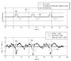
도 3은 종래의 차량 제어를 설명하기 위한 도면이다.3 is a diagram for explaining a conventional vehicle control.
도 3의 상단 그래프를 참조하면, 그래프 301은 차선을 나타내고, 그래프 302는 차량의 차로 중앙으로부터의 차량의 위치를 나타낸다. 그래프 303은 사각지역 검출 시스템 및 차체 자세 제어 시스템에 의한 편제동 인가 여부를 나타낸다. 그래프 302를 살펴보면 약 5초, 16초, 27초부터 차량은 차로 중앙으로부터 (그래프 상에서의) 상단의 차선으로 이동한다. 약 7초, 18초, 29초에 이르면 차량은 차선에 도달하게 되는데, 사각지역 검출 시스템은 약 6~7초, 17~18초, 28.5~29.5초 동안에 편제동을 구동계에게 인가하였다. 이것에 의하여 차량은 약 10초, 21초, 33초에서 오히려 반대편 차선으로 접근하였다. 이것은 차선 유지 보조 시스템만으로 차량의 안정적인 제어가 가능한 경우임에도 사각지역 검출 시스템에 의한 편제동과 차체 자세 제어 시스템에 의한 조향 제어가 동시에 수행된 경우로서, 이른바 차선 중앙 오버슈트가 발생한 경우이다.3, a
또한, 도 3의 하단 그래프는 도 3의 상단 그래프와 시간적으로 대응되는 그래프이다. 그래프 303은 편제동 인가 여부를 나타낸다. 그래프 304는 차량의 요-레이트, 그래프 305는 차량의 헤딩각을 나타낸다. 그래프 304를 살펴보면 편제동이 인가된 약 6~7초, 17~18초, 28.5~29.5초 동안에 요-레이트가 급격하게 증가하여 거의 -4˚/sec 에 육박하고 있다. 이것은 차량에 탑승한 운전자의 승차감을 저해할 수 있음과 아울러, 급격한 방향 변동으로 운전자에게 불안감을 안겨줄 수도 있다.3 is a graph corresponding to the top graph of FIG. 3 in terms of time. A
도 4는 본 발명의 다양한 실시예에 따른 통합 제어를 설명하기 위한 도면이다.4 is a diagram for explaining integrated control according to various embodiments of the present invention.
도 4의 상단 그래프를 참조하면, 그래프 401은 차선을 나타내고, 그래프 402는 차량의 차로 중앙으로부터의 차량의 위치를 나타낸다. 그래프 403은 능동형 사각지역 검출 시스템(ABSD)(101) 및 차체 자세 제어 모듈(ESC)(102)에 의한 편제동 인가 여부를 나타낸다. 그래프 404는 차선 이탈 여부를 나타내고, 그래프 405는 차선 이탈 신호를 나타낸다. 그래프 402를 살펴보면 약 2초, 13초, 21초부터 차량은 차로 중앙으로부터 (그래프 상에서의) 상단의 차선으로 이동한다. 약 6초, 15초, 24초에 이르면 차량은 차선에 도달하게 되는데, 통합 제어 모듈(106)의 제어 하에 능동형 사각지역 검출 시스템(ABSD)(101)은 약 14.5~15.5초 및 23.5~24.5초 동안에 편제동을 구동계(105)에게 인가하였다. 즉, 6초 부근에서는 차량이 차선에 이러렀음에도 불구하고 편제동이 구동계(105)에 인가되지 않고, 구동계(105)에서는 차선 유지 보조 시스템(LKAS)(103) 및 전동식 조향 모듈(MDPS)(104)에 의한 조향 제어만 수행된다. 또한, 능동형 사각지역 검출 시스템(ABSD)(101) 및 차선 유지 보조 시스템(LKAS)(103)을 통합하여 제어하므로, 그래프 전 구간에 있어서 차선 중앙 오버슈트가 발행하지 않은 것을 확인할 수 있다.4, a
또한, 도 4의 하단 그래프는 도 3의 상단 그래프와 시간적으로 대응되는 그래프이다. 그래프 403은 편제동 인가 여부를 나타낸다. 그래프 406는 차량의 요-레이트, 그래프 407는 차량의 헤딩각을 나타낸다. 그래프 406을 살펴보면 편제동이 인가된 약 14.5~15.5초 및 23.5~24.5초 동안에 요-레이트가 급격하게 증가하기는 하나, 약 -2˚/sec 부근에서 유지되고 있는 것을 확인할 수 있다. 이것은 종래의 기술과 비교하여 약 절반에 불과한 것으로, 요-레이트의 변동이 줄어든 만큼 운전자에게 향상된 승차감을 제공할 수 있다.4 is a graph corresponding in time to the top graph of FIG. A
한편, 전술한 바와 같은 본 발명의 다양한 실시예에 따른 이상 차량 처리 방법은 컴퓨터 프로그램으로도 작성이 가능하다. 그리고 상기 프로그램을 구성하는 코드 및 코드 세그먼트는 당해 분야의 컴퓨터 프로그래머에 의하여 용이하게 추론될 수 있다. 또한, 상기 작성된 프로그램은 컴퓨터가 읽을 수 있는 기록매체(정보저장매체)에 저장되고, 컴퓨터에 의하여 판독되고 실행됨으로써 본 발명의 방법을 구현할 수 있다. 그리고 상기 기록매체는 컴퓨터가 판독할 수 있는 모든 형태의 기록매체를 포함한다.Meanwhile, the abnormal vehicle processing method according to various embodiments of the present invention as described above can also be implemented by a computer program. And the code and code segments constituting the program can be easily deduced by a computer programmer in the field. In addition, the created program can be stored in a computer-readable recording medium (information storage medium), and can be read and executed by a computer to implement the method of the present invention. And the recording medium includes all types of recording media readable by a computer.
본 발명에서 설명하는 특정 실행들은 일 실시예들로서, 어떠한 방법으로도 본 발명의 범위를 한정하는 것은 아니다. 명세서의 간결함을 위하여, 종래의 회로 구성들, 제어 시스템들, 소프트웨어, 상기 시스템들의 다른 기능적인 측면들의 기재는 생략될 수 있다. 또한, 도면에 도시된 구성 요소들 간의 선들의 연결 또는 연결 부재들은 기능적인 연결 및/또는 물리적 또는 회로적 연결들을 예시적으로 나타낸 것으로서, 실제 장치에서는 대체 가능하거나 추가의 다양한 기능적인 연결, 물리적인 연결, 또는 회로 연결들로서 나타내어질 수 있다. 또한, “필수적인”, “중요하게” 등과 같이 구체적인 언급이 없다면 본 발명의 적용을 위하여 반드시 필요한 구성 요소가 아닐 수 있다.The specific acts described in the present invention are, by way of example, not intended to limit the scope of the invention in any way. For brevity of description, descriptions of conventional circuit configurations, control systems, software, and other functional aspects of the systems may be omitted. Also, the connections or connecting members of the lines between the components shown in the figures are illustrative of functional connections and / or physical or circuit connections, which may be replaced or additionally provided by a variety of functional connections, physical Connection, or circuit connections. Also, unless stated otherwise such as " essential ", " importantly ", etc., it may not be a necessary component for application of the present invention.
본 발명의 명세서(특히 특허청구범위에서)에서 “상기”의 용어 및 이와 유사한 지시 용어의 사용은 단수 및 복수 모두에 해당하는 것일 수 있다. 또한, 본 발명에서 범위(range)를 기재한 경우 상기 범위에 속하는 개별적인 값을 적용한 발명을 포함하는 것으로서(이에 반하는 기재가 없다면), 발명의 상세한 설명에 상기 범위를 구성하는 각 개별적인 값을 기재한 것과 같다. 본 발명에서 모든 예들 또는 예시적인 용어(예들 들어, 등등)의 사용은 단순히 본 발명을 상세히 설명하기 위한 것으로서 특허청구범위에 의해 한정되지 않는 이상 상기 예들 또는 예시적인 용어로 인해 본 발명의 범위가 한정되는 것은 아니다. 또한, 당업자는 다양한 수정, 조합 및 변경이 부가된 특허청구범위 또는 그 균등물의 범주 내에서 설계 조건 및 팩터에 따라 구성될 수 있음을 알 수 있다.The use of the terms " above " and similar indication words in the specification of the present invention (particularly in the claims) may refer to both singular and plural. In addition, in the present invention, when a range is described, it includes the invention to which the individual values belonging to the above range are applied (unless there is contradiction thereto), and each individual value constituting the above range is described in the detailed description of the invention The same. The use of all examples or exemplary language (e.g., etc.) in this invention is for the purpose of describing the present invention only in detail and is not to be limited by the scope of the claims, It is not. It will also be appreciated by those skilled in the art that various modifications, combinations, and alterations may be made depending on design criteria and factors within the scope of the appended claims or equivalents thereof.
이상에서 설명한 본 발명은, 본 발명이 속하는 기술 분야에서 통상의 지식을 가진 자에게 있어 본 발명의 기술적 사상을 벗어나지 않는 범위 내에서 여러 가지 치환, 변형 및 변경이 가능하므로 전술한 실시예 및 첨부된 도면에 의해 한정되는 것이 아니다.It will be apparent to those skilled in the art that various modifications and variations can be made in the present invention without departing from the spirit or scope of the invention. The present invention is not limited to the drawings.
1: 통합 제어 시스템
101: 능동형 사각지역 검출 시스템(ABSD)
102: 차체 자세 제어 모듈(ESC)
103: 차선 유지 보조 시스템(LKAS)
104: 전동식 조향 모듈(MDPS)
105: 구동계
106: 통합 제어 모듈
107: 속도 검출 센서 차선 검출 센서
108: 요-레이트 검출 센서
109: 헤딩각 검출 센서
110: 측후방 감지 센서1: Integrated control system
101: Active rectangular area detection system (ABSD)
102: Body Position Control Module (ESC)
103: Lane keeping assist system (LKAS)
104: Electric steering module (MDPS)
105: Driveline
106: Integrated control module
107: Speed detection sensor lane detection sensor
108: Y-rate detection sensor
109: Heading angle detection sensor
110: Side rear detection sensor
Claims (12)
Translated fromKorean타 차량이 사각지역에 위치하는 경우 상기 타 차량과의 충돌예측시간을 산출하는 사각지역 검출 모듈;
상기 차량의 차선 이탈 여부를 모니터링하고, 상기 차량이 차선을 이탈하는 경우 상기 구동계로 조향각 제어명령을 전송하는 차선 유지 보조 모듈; 및
상기 차량이 상기 차선을 이탈하고, 상기 타 차량이 상기 사각지역에 위치하면, 상기 충돌예측시간을 이용하여 횡방향 예측 이동거리를 산출하고, 상기 횡방향 예측 이동거리가 소정의 값 이상이면, 상기 사각지역 검출 모듈로 하여금 편제동 제어명령을 상기 구동계로 전송하도록 하고 상기 차선 유지 보조 모듈로 하여금 상기 조향각 제어명령을 상기 구동계로 전송하도록 하는 통합 제어 모듈을 포함하되,
상기 통합 제어 모듈은,
상기 횡방향 예측 이동거리가 상기 소정의 값 미만이면 상기 차선 유지 보조 모듈만으로 하여금 상기 조향각 제어명령을 상기 구동계로 전송하도록 하는 것을 특징으로 하는 통합 제어 시스템.A driving system for steering and driving the vehicle;
A rectangular area detection module for calculating a collision prediction time with the other vehicle when the other vehicle is located in a rectangular area;
A lane keeping auxiliary module for monitoring whether or not the vehicle has departed from the lane and transmitting a steering angle control command to the driveline when the vehicle leaves the lane; And
Calculating a lateral predicted movement distance using the collision prediction time if the vehicle departs from the lane and the other vehicle is located in the rectangular area, and if the lateral predicted movement distance is greater than or equal to a predetermined value, And an integrated control module for causing the rectangular area detection module to transmit a brake braking control command to the driving system and causing the lane keeping auxiliary module to transmit the steering angle control command to the driving system,
The integrated control module,
And when the lateral predicted moving distance is less than the predetermined value, only the lane-keeping auxiliary module transmits the steering angle control command to the driving system.
상기 사각지역 검출 모듈은,
차체 자세 제어 모듈을 통하여 상기 편제동 제어명령을 상기 구동계로 전송하는 것을 특징으로 하는 통합 제어 시스템.The method according to claim 1,
The rectangular area detection module includes:
And transmits the braking control command to the drive system through the body posture control module.
상기 차선 유지 보조 모듈은,
전동식 조향 모듈을 통하여 상기 조향각 제어명령을 상기 구동계로 전송하는 것을 특징으로 하는 통합 제어 시스템.The method according to claim 1,
The lane-keeping assistant module
And the steering angle control command is transmitted to the driving system through an electric steering module.
상기 통합 제어 모듈은,
상기 충돌예측시간, 상기 차량의 속도, 상기 차량의 헤딩각(heading angle), 상기 차량의 요-레이트(yaw-rate), 및 상기 차선의 곡률을 이용하여 상기 횡방향 예측 이동거리를 산출하는 것을 특징으로 하는 통합 제어 시스템.The method according to claim 1,
The integrated control module,
The lateral predicted moving distance is calculated using the collision prediction time, the speed of the vehicle, the heading angle of the vehicle, the yaw-rate of the vehicle, and the curvature of the lane Features integrated control system.
상기 사각지역 검출 모듈은,
상기 차량의 속도가 소정의 속도 이상일 경우에만 상기 타 차량과의 충돌예측시간을 산출하는 것을 특징으로 하는 통합 제어 시스템.The method according to claim 1,
The rectangular area detection module includes:
And calculates a collision prediction time with the other vehicle only when the speed of the vehicle is equal to or higher than a predetermined speed.
상기 차선 유지 보조 시스템이 차선 이탈을 감지하는 단계;
상기 사각지역 검출 시스템이 사각지역에 타 차량이 위치한 것을 감지하고, 상기 타 차량과의 충돌예측시간을 산출하는 단계;
상기 충돌예측시간을 이용하여 횡방향 예측 이동거리를 산출하는 단계;
상기 횡방향 예측 이동거리가 소정의 값 이상이면, 상기 사각지역 검출 시스템으로 하여금 편제동 제어명령을 구동계로 전송케 하고, 상기 차선 유지 보조 시스템으로 하여금 조향각 제어명령을 상기 구동계로 전송케 하는 단계; 및
상기 횡방향 예측 이동거리가 상기 소정의 값 미만이면, 상기 차선 유지 보조 시스템만으로 하여금 상기 조향각 제어명령을 상기 구동계로 전송하도록 하는 단계를 포함하는 방법.A method for integrally controlling a rectangular area detection system and a lane-keeping assist system mounted on a vehicle,
The lane-maintaining assist system detecting lane departure;
Detecting the position of another vehicle in the rectangular area of the rectangular area detection system and calculating a collision prediction time with the other vehicle;
Calculating a lateral prediction movement distance using the collision prediction time;
If the lateral predicted moving distance is equal to or greater than a predetermined value, causing the rectangular area detection system to transmit a knock control command to the driving system, and causing the lane-keeping auxiliary system to transmit a steering angle control command to the driving system; And
And causing only the lane-keeping auxiliary system to transmit the steering angle control command to the driving system when the lateral predicted moving distance is less than the predetermined value.
상기 편제동 제어명령은, 차체 자세 제어 모듈을 통하여 전송되는 것을 특징으로 하는 방법.The method of claim 7,
Wherein the one-way braking control command is transmitted through the vehicle body posture control module.
상기 조향각 제어명령은, 전동식 조향 모듈을 통하여 전송되는 것을 특징으로 하는 방법.The method of claim 7,
Wherein the steering angle control command is transmitted through an electric steering module.
상기 횡방향 예측 이동거리는,
상기 충돌예측시간, 상기 차량의 속도, 상기 차량의 헤딩각, 상기 차량의 요-레이트, 및 상기 차선의 곡률에 기초하여 산출되는 것을 특징으로 하는 방법.The method of claim 7,
The lateral predicted moving distance may be,
Wherein the calculation is performed based on the collision prediction time, the velocity of the vehicle, the heading angle of the vehicle, the yaw rate of the vehicle, and the curvature of the lane.
상기 충돌예측시간은,
상기 차량의 속도가 소정의 속도 이상일 경우에만 산출되는 것을 특징으로 하는 방법.The method of claim 7,
The collision prediction time is a time
And only when the speed of the vehicle is equal to or higher than a predetermined speed.
Priority Applications (2)
| Application Number | Priority Date | Filing Date | Title |
|---|---|---|---|
| KR1020140169829AKR101655587B1 (en) | 2014-12-01 | 2014-12-01 | Integrative method and system for controlling blind spot detection system and lane keeping assist system |
| US14/731,240US9434383B2 (en) | 2014-12-01 | 2015-06-04 | Integrative method and system for controlling blind spot detection system and lane keeping assist system |
Applications Claiming Priority (1)
| Application Number | Priority Date | Filing Date | Title |
|---|---|---|---|
| KR1020140169829AKR101655587B1 (en) | 2014-12-01 | 2014-12-01 | Integrative method and system for controlling blind spot detection system and lane keeping assist system |
Publications (2)
| Publication Number | Publication Date |
|---|---|
| KR20160065615A KR20160065615A (en) | 2016-06-09 |
| KR101655587B1true KR101655587B1 (en) | 2016-09-07 |
Family
ID=56078672
Family Applications (1)
| Application Number | Title | Priority Date | Filing Date |
|---|---|---|---|
| KR1020140169829AActiveKR101655587B1 (en) | 2014-12-01 | 2014-12-01 | Integrative method and system for controlling blind spot detection system and lane keeping assist system |
Country Status (2)
| Country | Link |
|---|---|
| US (1) | US9434383B2 (en) |
| KR (1) | KR101655587B1 (en) |
Families Citing this family (14)
| Publication number | Priority date | Publication date | Assignee | Title |
|---|---|---|---|---|
| JP6412460B2 (en)* | 2015-04-14 | 2018-10-24 | 株式会社Soken | Travel path estimation device |
| KR102592199B1 (en)* | 2016-09-22 | 2023-10-20 | 현대자동차주식회사 | Method for setting alerting area of vehicle and bind spot detection system for making the same |
| US10403145B2 (en)* | 2017-01-19 | 2019-09-03 | Ford Global Technologies, Llc | Collison mitigation and avoidance |
| JP6897453B2 (en)* | 2017-09-26 | 2021-06-30 | トヨタ自動車株式会社 | Driving support device |
| CN107804319B (en)* | 2017-10-20 | 2020-06-02 | 东风汽车集团有限公司 | A lane keeping assist method and system based on blind spot monitoring |
| DE102018200054A1 (en) | 2018-01-03 | 2019-07-04 | Ford Global Technologies, Llc | Device for blind spot monitoring of a motor vehicle |
| DE102018203287B4 (en)* | 2018-03-06 | 2024-03-07 | Audi Ag | Method and system for operating a lane keeping assistance device of a motor vehicle |
| KR20200028217A (en)* | 2018-09-06 | 2020-03-16 | 현대자동차주식회사 | Apparatus for controlling driving of a vehicle and method thereof |
| JP2020075665A (en)* | 2018-11-09 | 2020-05-21 | トヨタ自動車株式会社 | Vehicle running control device |
| CN110341708B (en)* | 2019-08-21 | 2021-01-15 | 浙江吉利汽车研究院有限公司 | Automatic driving control method and system for blind area |
| US11884252B2 (en)* | 2019-08-29 | 2024-01-30 | Ford Global Technologies, Llc | Enhanced threat assessment |
| JP7529534B2 (en) | 2020-10-26 | 2024-08-06 | 株式会社ジェイテクト | Vehicle alarm system |
| KR20230087631A (en)* | 2021-12-08 | 2023-06-19 | 현대모비스 주식회사 | Method, apparatus, storage medium, vehicle for prventing collision in vehicle blind spot |
| CN117901822B (en)* | 2024-03-20 | 2024-05-28 | 衢州海易科技有限公司 | Anti-collision braking method and system for inner wheel difference area of engineering vehicle |
Family Cites Families (28)
| Publication number | Priority date | Publication date | Assignee | Title |
|---|---|---|---|---|
| US8255144B2 (en)* | 1997-10-22 | 2012-08-28 | Intelligent Technologies International, Inc. | Intra-vehicle information conveyance system and method |
| ES2391556T3 (en)* | 2002-05-03 | 2012-11-27 | Donnelly Corporation | Object detection system for vehicles |
| DE10342528A1 (en)* | 2003-09-12 | 2005-04-14 | Robert Bosch Gmbh | Method and device for driver assistance |
| DE102004004492A1 (en)* | 2004-01-29 | 2005-08-18 | Robert Bosch Gmbh | Radar system for motor vehicles |
| DE102005027653A1 (en)* | 2005-06-15 | 2006-12-21 | Robert Bosch Gmbh | Blind spot`s object detecting device, has comparison unit ascertaining, based on preset correlations between detection signals whether vehicle following host vehicle is present, and blocking output unit from outputting warning signal |
| DE102005052034A1 (en)* | 2005-10-31 | 2007-05-03 | Robert Bosch Gmbh | Lane keeping support system for motor vehicle, has steering controller, where steering characteristics of system is modified while cornering, such that smaller steering force is exerted on steering in direction of curve inner side |
| US7835836B2 (en)* | 2006-11-08 | 2010-11-16 | Gm Global Technology Operations, Inc. | Methods, systems, and computer program products for calculating a torque overlay command in a steering control system |
| JP4984837B2 (en)* | 2006-11-09 | 2012-07-25 | トヨタ自動車株式会社 | Vehicle warning system and vehicle warning method |
| JP2008273360A (en) | 2007-04-27 | 2008-11-13 | Hitachi Ltd | Vehicle motion control apparatus and method |
| KR101188491B1 (en) | 2008-02-18 | 2012-10-05 | 주식회사 만도 | Method And Apparatus for Preventing Steering Pull for Vehicle by Using Video Signal |
| JP5266926B2 (en) | 2008-07-23 | 2013-08-21 | 日産自動車株式会社 | Lane maintenance support device and lane maintenance support method |
| CN102396008B (en)* | 2009-04-15 | 2014-12-31 | 丰田自动车株式会社 | Alarm output control device |
| US8232872B2 (en)* | 2009-12-03 | 2012-07-31 | GM Global Technology Operations LLC | Cross traffic collision alert system |
| DE102010029780A1 (en)* | 2010-06-08 | 2011-12-22 | Robert Bosch Gmbh | Device for lateral environment monitoring of a vehicle |
| KR101573550B1 (en) | 2010-11-22 | 2015-12-01 | 현대자동차주식회사 | Method for setting control time of Lane Keeping Assist System |
| DE102010062696A1 (en)* | 2010-12-09 | 2012-06-14 | Robert Bosch Gmbh | Method and device for calibrating and adjusting a vehicle environment sensor. |
| US8698639B2 (en)* | 2011-02-18 | 2014-04-15 | Honda Motor Co., Ltd. | System and method for responding to driver behavior |
| JP2012232704A (en) | 2011-05-09 | 2012-11-29 | Jtekt Corp | Vehicle steering device |
| EP2591983B1 (en) | 2011-11-11 | 2018-01-10 | Volvo Car Corporation | Method and system for adaptation of a steering wheel torque overlay of a lane keeping aid system |
| US9007198B2 (en)* | 2012-11-02 | 2015-04-14 | Toyota Motor Engineering & Manufacturing North America, Inc. | Adaptive Actuator interface for active driver warning |
| KR101987636B1 (en)* | 2012-11-09 | 2019-09-30 | 현대모비스 주식회사 | Control method for collision avoidance of vehicle and Apparatus for collision avoidance of vehicle implementing the same |
| KR101956020B1 (en) | 2012-12-18 | 2019-03-08 | 현대자동차 주식회사 | System of total control for electric 4 wheel drive system and method thereof |
| US20140184399A1 (en)* | 2012-12-31 | 2014-07-03 | Kia Motors Corporation | Rear collision warning alert system and method |
| US8874301B1 (en)* | 2013-07-09 | 2014-10-28 | Ford Global Technologies, Llc | Autonomous vehicle with driver presence and physiological monitoring |
| JP5673748B2 (en) | 2013-07-16 | 2015-02-18 | トヨタ自動車株式会社 | Vehicle control device |
| JP2016536703A (en)* | 2013-09-05 | 2016-11-24 | ローベルト ボッシュ ゲゼルシャフト ミット ベシュレンクテル ハフツング | Altitude lane departure warning based on data from rear radar sensor |
| US9145147B1 (en)* | 2014-03-04 | 2015-09-29 | Ford Global Technologies, Llc | Method and system for warning a driver of a motor vehicle |
| EP2942765B1 (en)* | 2014-05-07 | 2018-12-26 | Honda Research Institute Europe GmbH | Method and system for predictive lane change assistance, program software product and vehicle |
- 2014
- 2014-12-01KRKR1020140169829Apatent/KR101655587B1/enactiveActive
- 2015
- 2015-06-04USUS14/731,240patent/US9434383B2/enactiveActive
Also Published As
| Publication number | Publication date |
|---|---|
| US20160152234A1 (en) | 2016-06-02 |
| US9434383B2 (en) | 2016-09-06 |
| KR20160065615A (en) | 2016-06-09 |
Similar Documents
| Publication | Publication Date | Title |
|---|---|---|
| KR101655587B1 (en) | Integrative method and system for controlling blind spot detection system and lane keeping assist system | |
| EP3078515B1 (en) | Collision avoidance based on front wheel off tracking during reverse operation | |
| KR101987636B1 (en) | Control method for collision avoidance of vehicle and Apparatus for collision avoidance of vehicle implementing the same | |
| US9081387B2 (en) | Method and device for the prediction and adaptation of movement trajectories of motor vehicles | |
| US9168921B2 (en) | Method for warning a driver of a motor vehicle of an obstacle present in a side area next to a side flank of the vehicle and motor vehicle with a driver assistance system | |
| CN106476800B (en) | Collision avoids auxiliary device | |
| US9037379B2 (en) | Apparatus and method for providing a crash prevention control functionality for a vehicle | |
| US9508261B2 (en) | Method and device for operating a vehicle | |
| JP5510255B2 (en) | Vehicle operation state determination system | |
| KR101691322B1 (en) | Vehicle control system | |
| US9569968B2 (en) | Method and device for the automated braking and steering of a vehicle | |
| KR101478068B1 (en) | Apparatus for preventing collision in vehicle and method thereof | |
| US8531313B2 (en) | Method for operating a driver assistance system when parking a vehicle in a parking space | |
| KR20140126975A (en) | Apparatus and method for preventing collision of vehicle | |
| US9283958B2 (en) | Method and device for assisting in returning a vehicle after leaving a roadway | |
| KR20150140805A (en) | Vehicle control system | |
| US20140343792A1 (en) | Driving assistance apparatus for vehicle | |
| CN104709280B (en) | vehicle anti-collision system and method | |
| KR102228393B1 (en) | Rear collision warning control method and apparatus | |
| US11591021B2 (en) | Method for preparing and/or performing a steering intervention that assists the driver of a vehicle | |
| KR20170104267A (en) | Active safety system for a personal mobility vehicle | |
| JP5459002B2 (en) | Vehicle control device | |
| CN108202740A (en) | Anticollision auxiliary system and method | |
| TWI552901B (en) | Vehicle collision avoidance system and method |
Legal Events
| Date | Code | Title | Description |
|---|---|---|---|
| A201 | Request for examination | ||
| PA0109 | Patent application | St.27 status event code:A-0-1-A10-A12-nap-PA0109 | |
| PA0201 | Request for examination | St.27 status event code:A-1-2-D10-D11-exm-PA0201 | |
| R18-X000 | Changes to party contact information recorded | St.27 status event code:A-3-3-R10-R18-oth-X000 | |
| E902 | Notification of reason for refusal | ||
| PE0902 | Notice of grounds for rejection | St.27 status event code:A-1-2-D10-D21-exm-PE0902 | |
| E13-X000 | Pre-grant limitation requested | St.27 status event code:A-2-3-E10-E13-lim-X000 | |
| P11-X000 | Amendment of application requested | St.27 status event code:A-2-2-P10-P11-nap-X000 | |
| P13-X000 | Application amended | St.27 status event code:A-2-2-P10-P13-nap-X000 | |
| PG1501 | Laying open of application | St.27 status event code:A-1-1-Q10-Q12-nap-PG1501 | |
| E701 | Decision to grant or registration of patent right | ||
| PE0701 | Decision of registration | St.27 status event code:A-1-2-D10-D22-exm-PE0701 | |
| P22-X000 | Classification modified | St.27 status event code:A-2-2-P10-P22-nap-X000 | |
| GRNT | Written decision to grant | ||
| PR0701 | Registration of establishment | St.27 status event code:A-2-4-F10-F11-exm-PR0701 | |
| PR1002 | Payment of registration fee | St.27 status event code:A-2-2-U10-U11-oth-PR1002 Fee payment year number:1 | |
| PG1601 | Publication of registration | St.27 status event code:A-4-4-Q10-Q13-nap-PG1601 | |
| R18-X000 | Changes to party contact information recorded | St.27 status event code:A-5-5-R10-R18-oth-X000 | |
| FPAY | Annual fee payment | Payment date:20190827 Year of fee payment:4 | |
| PR1001 | Payment of annual fee | St.27 status event code:A-4-4-U10-U11-oth-PR1001 Fee payment year number:4 | |
| PR1001 | Payment of annual fee | St.27 status event code:A-4-4-U10-U11-oth-PR1001 Fee payment year number:5 | |
| P22-X000 | Classification modified | St.27 status event code:A-4-4-P10-P22-nap-X000 | |
| PR1001 | Payment of annual fee | St.27 status event code:A-4-4-U10-U11-oth-PR1001 Fee payment year number:6 | |
| PR1001 | Payment of annual fee | St.27 status event code:A-4-4-U10-U11-oth-PR1001 Fee payment year number:7 | |
| PR1001 | Payment of annual fee | St.27 status event code:A-4-4-U10-U11-oth-PR1001 Fee payment year number:8 | |
| PR1001 | Payment of annual fee | St.27 status event code:A-4-4-U10-U11-oth-PR1001 Fee payment year number:9 | |
| PR1001 | Payment of annual fee | St.27 status event code:A-4-4-U10-U11-oth-PR1001 Fee payment year number:10 |