KR101655512B1 - Image capturing device and image capturing method - Google Patents
Image capturing device and image capturing methodDownload PDFInfo
- Publication number
- KR101655512B1 KR101655512B1KR1020137023357AKR20137023357AKR101655512B1KR 101655512 B1KR101655512 B1KR 101655512B1KR 1020137023357 AKR1020137023357 AKR 1020137023357AKR 20137023357 AKR20137023357 AKR 20137023357AKR 101655512 B1KR101655512 B1KR 101655512B1
- Authority
- KR
- South Korea
- Prior art keywords
- image
- color
- subject
- quot
- information
- Prior art date
- Legal status (The legal status is an assumption and is not a legal conclusion. Google has not performed a legal analysis and makes no representation as to the accuracy of the status listed.)
- Expired - Fee Related
Links
Images


Classifications
- H—ELECTRICITY
- H04—ELECTRIC COMMUNICATION TECHNIQUE
- H04N—PICTORIAL COMMUNICATION, e.g. TELEVISION
- H04N5/00—Details of television systems
- H04N5/30—Transforming light or analogous information into electric information
- H04N5/33—Transforming infrared radiation
- G—PHYSICS
- G01—MEASURING; TESTING
- G01J—MEASUREMENT OF INTENSITY, VELOCITY, SPECTRAL CONTENT, POLARISATION, PHASE OR PULSE CHARACTERISTICS OF INFRARED, VISIBLE OR ULTRAVIOLET LIGHT; COLORIMETRY; RADIATION PYROMETRY
- G01J3/00—Spectrometry; Spectrophotometry; Monochromators; Measuring colours
- G01J3/28—Investigating the spectrum
- G01J3/2803—Investigating the spectrum using photoelectric array detector
- G—PHYSICS
- G01—MEASURING; TESTING
- G01J—MEASUREMENT OF INTENSITY, VELOCITY, SPECTRAL CONTENT, POLARISATION, PHASE OR PULSE CHARACTERISTICS OF INFRARED, VISIBLE OR ULTRAVIOLET LIGHT; COLORIMETRY; RADIATION PYROMETRY
- G01J3/00—Spectrometry; Spectrophotometry; Monochromators; Measuring colours
- G01J3/28—Investigating the spectrum
- G01J3/30—Measuring the intensity of spectral lines directly on the spectrum itself
- G01J3/32—Investigating bands of a spectrum in sequence by a single detector
- G—PHYSICS
- G01—MEASURING; TESTING
- G01J—MEASUREMENT OF INTENSITY, VELOCITY, SPECTRAL CONTENT, POLARISATION, PHASE OR PULSE CHARACTERISTICS OF INFRARED, VISIBLE OR ULTRAVIOLET LIGHT; COLORIMETRY; RADIATION PYROMETRY
- G01J3/00—Spectrometry; Spectrophotometry; Monochromators; Measuring colours
- G01J3/28—Investigating the spectrum
- G01J3/30—Measuring the intensity of spectral lines directly on the spectrum itself
- G01J3/36—Investigating two or more bands of a spectrum by separate detectors
- G—PHYSICS
- G01—MEASURING; TESTING
- G01J—MEASUREMENT OF INTENSITY, VELOCITY, SPECTRAL CONTENT, POLARISATION, PHASE OR PULSE CHARACTERISTICS OF INFRARED, VISIBLE OR ULTRAVIOLET LIGHT; COLORIMETRY; RADIATION PYROMETRY
- G01J3/00—Spectrometry; Spectrophotometry; Monochromators; Measuring colours
- G01J3/46—Measurement of colour; Colour measuring devices, e.g. colorimeters
- G01J3/50—Measurement of colour; Colour measuring devices, e.g. colorimeters using electric radiation detectors
- G01J3/51—Measurement of colour; Colour measuring devices, e.g. colorimeters using electric radiation detectors using colour filters
- H—ELECTRICITY
- H04—ELECTRIC COMMUNICATION TECHNIQUE
- H04N—PICTORIAL COMMUNICATION, e.g. TELEVISION
- H04N23/00—Cameras or camera modules comprising electronic image sensors; Control thereof
- H04N23/10—Cameras or camera modules comprising electronic image sensors; Control thereof for generating image signals from different wavelengths
- H04N23/11—Cameras or camera modules comprising electronic image sensors; Control thereof for generating image signals from different wavelengths for generating image signals from visible and infrared light wavelengths
- H—ELECTRICITY
- H04—ELECTRIC COMMUNICATION TECHNIQUE
- H04N—PICTORIAL COMMUNICATION, e.g. TELEVISION
- H04N23/00—Cameras or camera modules comprising electronic image sensors; Control thereof
- H04N23/20—Cameras or camera modules comprising electronic image sensors; Control thereof for generating image signals from infrared radiation only
- H—ELECTRICITY
- H04—ELECTRIC COMMUNICATION TECHNIQUE
- H04N—PICTORIAL COMMUNICATION, e.g. TELEVISION
- H04N23/00—Cameras or camera modules comprising electronic image sensors; Control thereof
- H04N23/56—Cameras or camera modules comprising electronic image sensors; Control thereof provided with illuminating means
- H—ELECTRICITY
- H04—ELECTRIC COMMUNICATION TECHNIQUE
- H04N—PICTORIAL COMMUNICATION, e.g. TELEVISION
- H04N23/00—Cameras or camera modules comprising electronic image sensors; Control thereof
- H04N23/80—Camera processing pipelines; Components thereof
- H04N23/84—Camera processing pipelines; Components thereof for processing colour signals
- H—ELECTRICITY
- H10—SEMICONDUCTOR DEVICES; ELECTRIC SOLID-STATE DEVICES NOT OTHERWISE PROVIDED FOR
- H10F—INORGANIC SEMICONDUCTOR DEVICES SENSITIVE TO INFRARED RADIATION, LIGHT, ELECTROMAGNETIC RADIATION OF SHORTER WAVELENGTH OR CORPUSCULAR RADIATION
- H10F39/00—Integrated devices, or assemblies of multiple devices, comprising at least one element covered by group H10F30/00, e.g. radiation detectors comprising photodiode arrays
- H10F39/10—Integrated devices
- H10F39/12—Image sensors
- G—PHYSICS
- G01—MEASURING; TESTING
- G01J—MEASUREMENT OF INTENSITY, VELOCITY, SPECTRAL CONTENT, POLARISATION, PHASE OR PULSE CHARACTERISTICS OF INFRARED, VISIBLE OR ULTRAVIOLET LIGHT; COLORIMETRY; RADIATION PYROMETRY
- G01J3/00—Spectrometry; Spectrophotometry; Monochromators; Measuring colours
- G01J3/28—Investigating the spectrum
- G01J3/2803—Investigating the spectrum using photoelectric array detector
- G01J2003/2806—Array and filter array
- G—PHYSICS
- G01—MEASURING; TESTING
- G01J—MEASUREMENT OF INTENSITY, VELOCITY, SPECTRAL CONTENT, POLARISATION, PHASE OR PULSE CHARACTERISTICS OF INFRARED, VISIBLE OR ULTRAVIOLET LIGHT; COLORIMETRY; RADIATION PYROMETRY
- G01J3/00—Spectrometry; Spectrophotometry; Monochromators; Measuring colours
- G01J3/28—Investigating the spectrum
- G01J3/2803—Investigating the spectrum using photoelectric array detector
- G01J2003/2813—2D-array
- H—ELECTRICITY
- H04—ELECTRIC COMMUNICATION TECHNIQUE
- H04N—PICTORIAL COMMUNICATION, e.g. TELEVISION
- H04N23/00—Cameras or camera modules comprising electronic image sensors; Control thereof
- H04N23/80—Camera processing pipelines; Components thereof
- H04N23/84—Camera processing pipelines; Components thereof for processing colour signals
- H04N23/843—Demosaicing, e.g. interpolating colour pixel values
Landscapes
- Physics & Mathematics (AREA)
- Spectroscopy & Molecular Physics (AREA)
- Engineering & Computer Science (AREA)
- Multimedia (AREA)
- Signal Processing (AREA)
- General Physics & Mathematics (AREA)
- Studio Devices (AREA)
- Color Television Image Signal Generators (AREA)
- Image Processing (AREA)
Abstract
Translated fromKoreanDescription
Translated fromKorean본 발명은 피사체에 반사된 적외선 또는 피사체가 방사하는 적외선 등에서 피사체의 컬러 화상을 형성하는 것이 가능토록 하는 화상촬영장치 및 화상촬영방법 등에 관한 것이다.BACKGROUND OF THE
종래 암흑 중의 피사체에 적외선을 조사하여 피사체의 컬러 화상을 형성하는 방법으로는 유사컬러 스케일 표시가 이용되었다.A similar color scale display is used as a method of forming a color image of a subject by irradiating infrared rays to a subject in the conventional darkness.
즉 피사체에서 반사된 적외선에서 얻어진 적외선 강도분포의 강도 레벨을 복수의 강도 레벨 구간으로 분할하여 각 강도 레벨 구간에 적당한 색을 할당함으로써 컬러화상을 형성하여 피사체의 적외선 컬러 화상으로서 표시하여 왔다.That is, the intensity level of the infrared ray intensity distribution obtained from the infrared ray reflected from the subject is divided into a plurality of intensity level sections, and a proper color is assigned to each intensity level section, thereby forming a color image and displaying it as an infrared color image of the subject.
그러나 유사컬러 스케일 표시를 실시하면 화상을 회색의 짙고 엷음으로 표시하는 그레이 스케일 표시(흑백표시) 및 단색 또는 원색의 컬러의 짙고 엷음으로 표시하는 단색 컬러 스케일 표시와 비교하여 어떠한 강도 레벨 구간을 추출하는 용도로는 유효하나 화상정보가 증가하지 않음으로 반대로 부자연스러우며 보기 힘든 경우도 적지 않았다.However, if a similar color scale display is performed, it is possible to extract a certain intensity level section in comparison with a gray scale display (monochrome display) in which an image is displayed in a dark gray color and a monochrome color scale display in which a monochrome or primary color is displayed in a dark color It is effective for the purpose, but the image information does not increase, so it is unnatural and it is hard to see.
한편 천문학의 분야에서는 종래부터 항성이나 성운이 방사하는 적외선을 복수의 적외선 밴드패스 필터를 이용하여 복수의 적외선화상을 형성하여 얻어진 각 적외선 화상을 적당한 복수의 색에 의하여 표색한 합성 컬러 화상을 형성하는 기술이 행하여져 왔다.On the other hand, in the field of astronomy, a composite color image is formed by coloring each infrared image obtained by forming a plurality of infrared images using a plurality of infrared band-pass filters from an infrared ray emitted from a star or nebula conventionally, Technology has been done.
그러나 이 합성 컬러화상은 가시광선에 의한 화상과는 전혀 무관계의 표색이므로 부자연스럽게 보이는 경우도 적지 않고 또한 적외선을 방사하지 않는 위성 등은 촬영할 수 없다.However, since this composite color image is a color image having no relation to an image by visible light, there are a few cases where it appears unnatural, and a satellite or the like that does not emit infrared rays can not be photographed.
한편 종래부터 단색의 적외선 사진과 통상의 가시광선 사진을 합성하여 합성컬러 사진을 형성하는 것도 행해지고 있다.On the other hand, conventionally, a monochromatic infrared photograph and a conventional visible light photograph are synthesized to form a composite color photograph.
그러나 이 합성 컬러사진도 현실의 배색과는 무관계이다. 그렇기 때문에 일견 환상적 또는 예술적으로 보이나 현실적이지 않기 때문에 부자연스럽게 보일 뿐 만 아니라 태양광선이 있는 낮 중에만 촬영할 수 있다.However, this composite color photograph is also irrelevant to the color of reality. So it looks fantastic or artistic at first glance, but it is unnatural because it is not realistic and it can only be photographed during daytime with sunlight.
한편 흑백, 비디오, 카메라와 적, 청 및 녹의 광을 발광하는 광원과 당 광원에서 적, 청 및 녹의 광을 순차 발광하게끔 제어하는 제어회로와 상기 광원이 적, 청 및 녹의 광을 발광할 시의 상기 비디오, 카메라의 출력 비디오신호를 순차 취입, 합성하여 컬러, 비디오신호로 만드는 취입 합성회로 등을 갖춘 컬러 정지화상 촬영장치가 제안되어 있다(예: 특허문헌1참조).A control circuit for controlling a light source emitting light of black and white, video, a camera, red, blue, and green, and light of red, blue, and green in the light source sequentially and a control circuit for controlling the light source to emit red, There has been proposed a color still picture photographing apparatus having a take-in synthesizing circuit for successively taking in and synthesizing output video signals of the video and camera into a color and a video signal (for example, refer to Patent Document 1).
그러나 특허문헌1의 컬러 정지화상 촬영장치는 가시광선 영역에 관한 것으로서 적외선은 대상이 되지 않는다.However, the color still picture image pickup apparatus of
또한 특허문헌1의 컬러 정지화상 촬영장치는 조사된 가시광선의 색과 같은 색으로 화상을 표색하여 가법혼색하는 것으로, 이점에 있어서 이하에 개시되는 본 발명의 일 측면 및 본 발명의 일 실시형태와는 다른 것이다.In addition, the color still image photographing apparatus of
한편 X선을 발생하는 X선 선원, 피검체를 투과한 X선을 검출하는 2차원의 X선 검출기, 환자 침대가 있으며, X선 선원은 환자 침대의 이동과 동기하여 연속회전 가능하며 피검체를 나선상으로 주사되는 X선 CT장치에 있어서, 피사체를 조사하는 X선의 에너지 특성을 슬라이스 방향으로 변경함으로써 가능한 에너지 변환수단을 가지며, 해당 에너지변경 수단을 이용하여 나선 스캔을 함으로서 동일 슬라이스 위치를 복수의 다른 실효 에너지의 X선으로 계측 가능하며 얻어진 데이터를 같은 실효 에너지로 실측한 데이터 간에 보완함으로써 임의의 실효 에너지의 화상, 임의의 실효 에너지의 화상 간 차이를 얻는 것을 가능하게 한 X선 CT장치가 제안되고 있다.(예: 특허문헌2참조).On the other hand, there is an X-ray source for generating X-rays, a two-dimensional X-ray detector for detecting X-rays transmitted through the object, and a patient bed, and the X-ray source can rotate continuously in synchronism with movement of the patient bed. An X-ray CT apparatus which scans in a helical manner has energy conversion means capable of changing the energy characteristic of an X-ray irradiating a subject in a slice direction. By performing a spiral scan using the energy changing means, An X-ray CT apparatus capable of measuring a difference between images of arbitrary effective energy and images of an effective energy can be obtained by complementing data obtained by measurement with X-ray of effective energy and data obtained by the same effective energy (See, for example, Patent Document 2).
그러나 특허문헌2의 X선 CT장치는 X선 영역에 관한 것으로서 적외선은 대상이 아니며, 또한 특허문헌2의 X선 CT장치는 X선 투과화상 촬영장치이며 본 발명과는 다른 것이고, 더욱이 특허문헌2의 X선 CT장치에 의한 컬러합성화상은 시인성을 향상시키기 위하여 착색시킨 자연과는 전혀 다른 표색을 하는 것으로서 적어도 이점에 있어서는 이하에 개시되는 본 발명의 일 측면 및 본 발명의 일 실시형태와는 다른 것이다.However, the X-ray CT apparatus of
한편 촬영동작에 의해 얻어진 광상을 각 파장 영역마다의 광상으로 하여 특정의 피사체화상을 추출하는 파장선택형 액정카메라장치에 있어서 광학적 밴드패스필터 기능을 가진 더욱이 그 중심파장을 전압에 의해 변경 가능한 액정필터와 그 액정필터에 의해 선택된 파장역의 광상을 광전 변환하여 영상신호를 생성하는 1개의 촬상소자와 그 촬상소자에서 출력된 파장이 다른 2개의 화상 간의 신호레벨차이를 계산하여 이 차이의 절대치에 기준한 영상신호를 생성하는 화상연산부를 갖춘 것을 특징으로 하는 파장선택형 액정카메라 장치가 제안되고 있다.(예: 특허문헌 3참조).On the other hand, in a wavelength-selective liquid crystal camera apparatus that extracts a specific subject image with the optical image obtained by the photographing operation as an optical image for each wavelength region, a liquid crystal filter having an optical bandpass filter function and capable of changing its central wavelength by a voltage A signal level difference between one image pickup element for photoelectrically converting an optical image in a wavelength region selected by the liquid crystal filter to generate a video signal and two images having different wavelengths output from the image pickup element is calculated and based on the absolute value of the difference There is proposed a wavelength selection type liquid crystal camera device having an image operation unit for generating a video signal (for example, refer to Patent Document 3).
그러나 특허문헌3의 파장선택형 액정필터는 1도에 1파장 역의 투과만이 가능하며 본 발명에 상당하는 것이 아니다.However, the wavelength selection type liquid crystal filter of
또한 특허문헌3의 파장선택형 액정카메라 장치는 파장이 다른 2개의 화상 간의 신호레벨 차이를 검출하여 영상화함으로써 시인성의 향상을 꾀하는 것으로 적어도 이점에 있어서는 이하에 개시되는 본 발명의 일 측면 및 본 발명의 일 실시형태와 다른 것이다.The wavelength selection type liquid crystal camera device of
또한 특허문헌3에 있어서 촬영동작에 의해 얻어진 광상을 각 파장역 마다의 광상으로 하여 특정의 피사체 화상을 추출하는 파장선택형 액정카메라 장치에 있어서의 광학적 밴드패스필터 기능을 가지며 더욱이 그 중심파장을 전압에 의한 변경가능한 액정필터와 그 액정필터에 의해 선택된 각 가장의 광상을 적색(R)영역, 녹색(G)영역, 청색(B)영역으로 분리하여 광전변환하여 R색 영상신호, G색 영상신호, B색 영상신호를 생성하는 컬러촬상소자와 그 컬러촬상소자에서 출력되는 R색 영상신호, G색 영상신호, B색 영상신호의 각 화소 마다에 신호레벨 차이를 계산하여 그 차이에 기준하여 R색 영상신호, G색 영상신호, B색 영상신호를 생성하는 컬러영상 연산부와 이 컬러영상 연산부로부터 출력되는 R색 영상신호, G색 영상신호, B색 영상신호를 합성하여 합성컬러 영상신호를 생성하는 컬러영상신호 합성부를 갖춘 것을 특징으로 하는 파장선택형 액정컬러카메라 장치도 제안되고 있다.Further,
그러나 특허문헌3의 이 액정필터는 광상을 적색(R)영역, 녹색(G)영역, 청색(B)영역으로 분리하는 것으로 대상으로 하고 있는 광은 가시광선으로 적어도 이점에 있어서는 이하에 개시되는 본 발명의 일 측면 및 본 발명의 일 실시형태에 상당하는 것이 아니다.However, this liquid crystal filter of
한편 대상물에서 방사 또는 반사되는 적외선을 수광하여 적외스펙트럼 화상을 얻는 적외선 카메라와 당해 대상물에 관하여 색과 적외스펙트럼 방사 강도 또는 적외스펙트럼 반사율과의 대응데이터를 사전에 기억하는 기억장치와 해당 데이터에 기준하여 전기 적외스펙트럼 화상의 각 위치에 있어서의 적외스펙트럼의 방사 강도 또는 적외스펙트럼 반사율의 값에서 전기 적외스펙트럼 화상의 각 위치에 있어서의 색을 결정하는 제1의 처리수단과 전기 제1의 처리수단으로 얻어진 색 정보를 기준으로 전기 대상물의 화상에 인공적으로 착색을 처리하는 제2의 처리수단을 갖춘 것을 특징으로 하는 적외선컬러 화상형성장치가 제안되고 있다.(예:특허문헌4참조).On the other hand, an infrared camera which receives infrared rays radiated or reflected from an object and obtains an infrared spectral image and a storage device for previously storing corresponding data of color and infrared spectral radiant intensity or infrared spectral reflectance with respect to the object, First and second processing means for determining the color at each position of the electric infrared spectral image at the radial intensity of the infrared spectrum or the infrared spectral reflectance at each position of the electric infrared spectral image, And second processing means for artificially coloring the image of the electric object on the basis of the color information (see, for example, Patent Document 4).
그러나 특허문헌4의 적외선 컬러 화상 형성장치는 대상물의 가시광선 영역에 있어서의 실제의 색과 적외선 스펙트럼 방사 강도 또는 적외스펙트럼 방사 강도 또는 적외스펙트럼 반사율과의 대응 데이터를 사전에 측정하여 준비할 필요가 있으며 사전의 피사체의 정밀한 가시광선 및 적외선스펙트럼 분광측정이 필요하다.However, in the infrared color image forming apparatus of
그러한 대응데이터, 대응데이터를 기억하는 기억장치 및 시간이 필요한바, 대응 데이터와의 비교에 기준하여 표색을 필요로 하지 않는 본 발명은 적어도 이점에 있어서는 틀린 것이다.Such a correspondence data, a storage device for storing the correspondence data, and a time required are not necessary for the present invention which does not require coloring based on a comparison with corresponding data.
한편 피사체에 적외선과 자외선을 조사하여 동 피사체를 촬영하여 얻은 적외선 화상신호에서 색을 판정함으로써 컬러화상신호를 출력하는 것을 특징으로 하는 암시 컬러카메라가 제안되고 있다.(예:특허문헌5, 특허문헌6참조).And a color image signal is output by irradiating the subject with infrared rays and ultraviolet rays to judge the color in the infrared image signal obtained by photographing the subject. (For example,
그러나 특허문헌5의 암시 컬러카메라는 자외선의 조사가 필수이나 본 발명은 그러한 자외선 조사를 필요로 하지 않는 점에서 구성을 달리한다.However, in the implicit color camera disclosed in
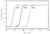
한편 광학계 내에 있어서 각각 서로 다른 적외파장 영역을 선택적으로 투과 또는 반사하는 복수의 광학필터와 복수의 광학필터에 의해 얻어진 적외광선을 각각 촬영하는 복수의 촬상수단과 복수의 촬상수단에 의해 얻어진 촬상신호에서 화상정보를 형성하는 신호처리 수단을 갖춘 것을 특징으로 하는 적외선 촬상장치가 제안되고 있다.(예: 특허문헌7참조).A plurality of optical filters for selectively transmitting or reflecting different infrared wavelength regions in the optical system and a plurality of image pickup means for respectively picking up infrared light obtained by the plurality of optical filters and image pickup signals obtained by a plurality of image pickup means There is proposed an infrared ray imaging apparatus having a signal processing means for forming image information (for example, refer to Patent Document 7).
그러나 특허문헌7의 적외촬상장치는 적외선만을 대상으로 한 촬상장치이며 가시광선하에서의 촬상과의 관계에 관하여는 기재되어 있지 않다.However, the infrared imaging device of
또한 가시광선에 의한 화상과 전혀 무관계의 표색이 이루어지며, 더욱이 적외선을 방사하지 않는 피사체 등은 촬영할 수 없다.In addition, the color of the image is completely irrelevant to the image by the visible light, and the subject or the like that does not emit infrared rays can not be photographed.
즉 적외선 조사에 의한 촬영에 의한 가시광선하에서의 피사체의 색을 재현하는 것은 개시되어 있지 않다.That is, it is not disclosed to reproduce the color of a subject under the visible light ray by photographing by infrared radiation.
한편 서로 다른 검출파장을 가진 적어도 2종류의 적외선 검출기를 2차원 어레이상에 배치한 적외선 고체촬상소자를 이용한 적외선 촬상장치에 있어서 적외선 화상을 컬러디스플레이상에 표시하여 검출파장이 다른 적외선 검출기로부터의 출력신호를 각각 컬러디스플레이 상의 다른 색소에 대응시켜 표시되는 것을 특징으로 하는 적외선촬상장치가 제안되고 있다.(예: 특허문헌8참조).On the other hand, in an infrared imaging apparatus using an infrared solid-state imaging device in which at least two types of infrared detectors having different detection wavelengths are arranged in a two-dimensional array or more, an infrared image is displayed on a color display, And the signal is displayed in association with another coloring matter on the color display, respectively (for example, refer to Patent Document 8).
그러나 특허문헌8의 적외선촬상장치는 적외선만을 대상으로 한 촬상장치이며 가시광선하에서의 촬상과의 관련에 관하여는 기재되고 있지 않다.However, the infrared ray imaging apparatus of
또한 가시광선에 의한 화상과는 전혀 무관계의 표색이고 더욱이 적외선을 방사하지 않는 피사체 등은 촬영할 수 없다.In addition, it is not possible to take a subject and the like that does not emit infrared rays and has a color of no relation with an image by visible light.
적외선 조사에 의한 촬상에 의한 가시광선하에서의 피사체의 색을 재현하는 것은 개시되어 있지 않다.It is not disclosed to reproduce the color of the object under visible light by imaging by infrared radiation.
한편 적외영역에 발광분포를 가진 적외선광원과 촬상렌즈와 적외영역 및 가시영역의 수광감도를 가진 수광소자가 매트릭스 상으로 배치된 CCD센서와 각각 특정의 파장영역의 가시광선 및 특정의 파장영역의 적외선을 투과하여 상기 수광소자의 각각에 부착되는 컬러필터를 구비하는 적외선 촬상장치로서 가시광선을 제외하고 적외선을 투과시키는 적외선 투과필터와 상기 이미지센서로의 적외선의 입광에 기준하여 촬상신호를 생성하는 촬상신호 생성수단과 상기 촬상신호를 디지털신호로 변환하는 디지털변환 수단과 상기 디지털변환 수단에 의해 변환된 디지털신호를 일시적으로 보유하는 메모리를 구비하는 것을 특징으로 하는 적외선촬상장치가 제안되고 있다.(예: 특허문헌9참조).A CCD sensor in which an infrared light source having a light emission distribution in an infrared region, an image pickup lens, and a light receiving element having a light receiving sensitivity in an infrared region and a visible region are arranged in a matrix, and a CCD sensor in which visible light in a specific wavelength region and infrared And a color filter attached to each of the light receiving elements, the apparatus comprising: an infrared ray transmission filter for transmitting infrared rays except visible rays; and an image pickup device for generating an image pickup signal on the basis of the infrared ray incident on the image sensor There is proposed an infrared imaging apparatus comprising a signal generating means, a digital converting means for converting the image pickup signal into a digital signal, and a memory for temporarily holding the digital signal converted by the digital converting means. : See Patent Document 9).
그러나 특허문헌9의 적외선촬상장치는 가시광선을 제외하여 적외선을 투과시키는 적외선투과 필터를 필요로 한다.However, the infrared ray image pickup apparatus of
한편 피사체를 촬영하여 전기 피사체로부터의 가시광성분에 기준하여 복수의 색 신호를 생성하여 전기 피사체로부터의 적외선 성분에 기준하여 적외선 휘도신호를 생성하는 촬상수단과 전기 촬상수단에 의해 생성된 각 색 신호 및 적외선 휘도신호에 기준하여 컬러화상을 생성하는 컬러 화상 생성 수단을 갖춘 촬상장치가 제안되고 있다.(예: 특허문헌10참조).An image pickup means for picking up a subject and generating a plurality of color signals based on visible light components from the electric subject to generate an infrared luminance signal based on an infrared ray component from the electric subject, There has been proposed an image pickup apparatus having color image generating means for generating a color image based on an infrared luminance signal (for example, refer to Patent Document 10).
그러나 특허문헌10의 촬상장치는 가시광선에 의한 촬상과 적외선에 의한 촬상을 합성하여 화상을 촬상하는 것으로 암흑에서의 컬러 촬상은 곤란하다.However, in the imaging device of
한편 현재의 트래픽 씬의 화상을 기사스펙트럼의 범위 외에 대응하는 카메라로 촬영하여 전기 화상을 차 내의 광학계 표시장치를 이용하여 가시스펙트럼으로 재현하는 형식으로 특히 야간이나 악천후 또는 안개 등이 있을 때 차량에 있어서의 시계를 개선하는 방법에 있어서 카메라에 의해 촬영된 트래픽 씬에 포함된 대상의 타입을 자동적으로 식별하여 타입에 따라 식별된 대상을 해당 대상이 주광하에서 가지고 있는 전형적인 휘도 및 또는 색에 상응하는 휘도 및 또는 색에 전기 광학계 표시장치에 표시하는 것을 특징으로 하는 차량에 있어서의 시야를 개선하는 방법이 제안되어 있다.(예: 특허문헌11참조).On the other hand, the image of the current traffic scene is photographed with a corresponding camera outside the range of the article spectrum, and the electric image is reproduced in the visible spectrum using the optical system display in the car. In the case where there is nighttime, bad weather, The method comprising the steps of automatically identifying a type of an object included in a traffic scene photographed by a camera and comparing the identified object with a typical luminance and / Or color is displayed on the electro-optical system display device (for example, refer to Patent Document 11).
그러나 특허문헌 11의 차량에 있어서의 시야를 개선하는 방법 및 장치는 비디오화상에 포함되는 모든 대상물의 타입을 식별하지 않으면 안되기 때문에 화상처리의 부담이 매우 커지는 문제가 있다.However, the method and apparatus for improving the visual field in the vehicle disclosed in
또한 흑백 또는 단색의 유사컬러에 의한 표시이기 때문에 위화감이 있다.In addition, there is a sense of incongruity because it is displayed by a similar color of monochrome or monochrome.
한편 가시광영역의 백색의 조명광과 가시광영역 이외의 파장영역의 광을 포함한 조명광을 선택적으로 피사체에 조명 가능한 조명수단과 가시광 영역 내의 다른 파장영역의 광을 투과하는 복수 종류의 필터로부터 만들어짐과 동시에 당해 필터가 가시광영역의 파장영역의 광도 투과하는 복투과특성을 가진 모자이크 필터이며 당해 모자이크 필터가 수광면에 장착되어 전기 조명수단에 의해 조명된 피사체상을 촬상하는 고체촬상소자가 설치된 내시경과 전기 피사체상을 촬상하는 것에 따라 전기 고체촬상 소자로부터 읽어진 출력신호에 대응하는 소망의 색을 할당 함으로서 컬러 화상을 얻는 수단을 특징으로 하는 내시경장치가 제안되고 있다.(예:특허문헌12참조).On the other hand, an illumination means capable of selectively illuminating an object including illumination light including white illumination light in a visible light region and light in a wavelength region other than the visible light region, and a plurality of kinds of filters transmitting light in different wavelength regions in the visible light region, An endoscope provided with a solid-state image pickup device for picking up an image of an object illuminated by an electric lighting means, the endoscope being mounted on the light-receiving surface, And a means for obtaining a color image by allocating a desired color corresponding to an output signal read from the electrical solid-state image pickup device by imaging the endoscope image (for example, see Patent Document 12).
그러나 특허문헌12의 내시경장치는 일반적인 가시광영역의 화상으로는 식별이 곤란한 피관찰체의 각 부위의 색조차를 검출하여 유사컬러로 표시하는 것을 가능하게 한 것으로 적외선 조사에 의한 촬상에 의한 가시광선하에서의 피사체의 색을 재현하는 것은 개시되어 있지 않다.However, in the endoscope apparatus of
한편 피사체의 샘플에서 방사되는 모든 파장영역의 방사광을 수광하여 당 방사광을 서로 다른 중심파장을 가진 n개(n≥3)의 성분광에 분광하는 분광광학부와 전기 n개의 성분광을 각각 광전 변환하여 전기 n개의 성분광에 각각 대응하는n개의 전기 신호를 각각 생성시키는 광전변환부와 전기 n개의 전기 신호를 가공함으로써 전기 샘플의 유사컬러 화상의 생성과 해당 유사컬러 화상의 색 표시를 행하기 위해 표색계에 기준하여 정의되는 수치의 산출을 행하는 화상처리부와 전기 유사컬러 화상 및/또는 전기 수치를 출력하는 화상출력부를 적어도 가지고 있고 전기 화상처리부는 전기 n개의 전기 신호에서 비롯되는 하나의 신호군에 대하여 m개(m≥3)의 감도관수의 각각을 독립으로 부과함으로써 각 감도관수에 대응한m개의 유사컬러 기본화상신호를 생성시켜 화상신호 생성처리수단과 전기 m개의 유사컬러 기본화상신호의 매트릭스M을 부과하여 벡터 변환하는 것에 의해 3개의 유사컬러 화상신호를 생성시키는 벡터변환처리수단과 전기 3개의 유사컬러 화상신호를 합성하여 전기 유사컬러 화상을 생성시키는 화상형성처리수단과 전기 3개의 유사컬러 화상신호를 이용하여 전기 표색계에 기준하여 정의되는 전기 수치를 산출하는 표색처리수단을 적어도 가지고 있으며 전기 m개의 감도관수는 전기 피사체 샘플이 속하는 피사체군을 구성하는 각 피사체간에 생기는 물리적 상태 또는 화학적 상태 또는 화학적 상태의 관측할 만한 차이와 전기 피사체군을 구성하는 각 피사체의 분관스펙트럼 간에 생기는 파형의 차이와의 간의 상관관계에 준하여 결정되며 전기 매트릭스M은 최적의 감도 특성에 다가가기 위한 매트릭스이며 효과적으로 전기 3개의 유서컬러 화상신호를 생성시킬 때에 만들어지는 색 재현 오차가 최소한이 되기 위하여 결정된 것임을 특징으로 하는 가시 및 불가시 영역의 색도 계측이 가능한 시스템이 제안되고 있다.(예: 특허문헌 13 참조).(N > = 3) component lights having different central wavelengths, and n component light beams are respectively converted to photoelectric conversion A photoelectric conversion unit for generating n electric signals respectively corresponding to the n component light beams, and electric n electric signals for producing a pseudo color image of the electric sample and color display of the pseudo color image An image processing section for calculating a value defined based on a colorimetric system and an image output section for outputting an electric quasi-color image and / or an electric value, wherein the electric image processing section comprises: each of m (m? 3) sensitivity irrigation densities is independently imposed, whereby m similar color bases corresponding to each sensitivity irrigation number A vector conversion processing means for generating an image signal and generating three similar color image signals by applying a matrix M of m similar color basic image signals and subjecting them to vector conversion; An image forming processing means for synthesizing signals to generate an electric color-similar color image, and a color image processing means for calculating an electric value defined on the basis of the electric colorimetric system using three similar color image signals. Is a correlation between the observable difference between the physical state or the chemical state or chemical state occurring between each subject constituting the subject group to which the electric subject sample belongs and the difference in the waveforms occurring between the incident spectra of the subjects constituting the electric subject group And the electric matrix M is determined based on the optimum sensitivity Which is a matrix for approaching the characteristic of the color image, and which is determined so as to minimize the color reproduction error generated when three electric color image signals are generated, has been proposed (See, for example, Patent Document 13).
그러나 특허문헌 13의 가시 및 불가시 영역의 색도계측이 가능한 시스템은 피사체 샘플로부터 취득하려는 소망의 정보를 불가시의 색 값 및 유사컬러 화상의 색표시를 이용하여 표준샘플과의 비교에 의해 평가하는 것으로 표준샘플의 준비가 필요하며 또한 넓은 파장범위에 걸쳐 세밀하게 분광하여야 하는 필요가 있음으로 화상처리의 부담이 매우 커지는 문제가 있다.However, in a system capable of measuring the chromaticity of the visible and invisible regions of
이상 상기에서 언급한 본원출원과 관련된 선행기술문헌은 아래와 같다.The prior art documents related to the present application mentioned above are as follows.
본 발명은 암흑에서도 가능한 한 자연의 배색을 가진 컬러 화상을 형성하는 것을 과제의 하나로 한다.One of the problems of the present invention is to form a color image having natural color as much as possible even in darkness.
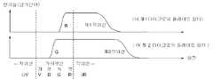
본 발명은 화상촬영수단의 일 적용예로서 조사부, 촬상부 및 표색설정부 등을 갖추고 조사부는 다른 파장강도분포를 가지는 적외선을 피사체에 조사하고, 촬상부는 피사체에 의해 반사된 다른 파장강도를 갖는 각각의 적외선에 의한 피사체의 화상을 촬상하여 각각의 화상을 나타내는 화상정보를 형성하며, 표색설정부는 형성된 화상정보가 나타내는 화상의 각각을 다른 단색에 의해 표색하기 위한 표색정보를 화상정보에 설정하는 수단 등을 포함하여 제공되는 화상촬영장치 및 화상촬영방법을 제공하고자 하는 목적을 갖는다.The present invention is an application example of an image photographing means that has an irradiating unit, an image pickup unit, a color setting unit and the like, and the irradiating unit irradiates the subject with infrared rays having different wavelength intensity distributions, and the image pick- And colorimetric setting unit sets colorimetric information for coloring each of the images represented by the formed image information by different monochromatic colors to image information, etc. An object of the present invention is to provide an image photographing apparatus and an image photographing method which are provided.
상기의 목적을 이루기 위하여 본 발명의 일 측면으로서 조사부, 촬상부 및 표색설정부를 갖추고, 전기 조사부는 다른 파장강도분포를 가진 적외선을 피사체에 조사하고, 전기 촬상부는 전기 피사체에 의해 반사되는 다른 파장강도분포를 가지는 각각의 적외선에 의한 전기 피사체의 화상을 촬상하여 각각의 화상을 나타내는 화상정보를 형성하고, 전기 표색설정부는 전기 형성된 화상정보가 나타내는 화상 각각을 다른 단색에 의해 표색하기 위한 표색정보를 전기 화상정보에 설정하는 것을 특징으로 하는 화상 촬상장치를 개시한다.According to an aspect of the present invention, there is provided an image processing apparatus including an irradiation unit, an image pickup unit, and a color setting unit. The electric irradiation unit irradiates an infrared ray having a different wavelength intensity distribution to a subject. And the electric-color-signal setting unit sets the color-matching information for coloring each of the images represented by the electro-formed image information by different monochromatic colors, And the image information is set in the image information.
더욱이 일반적으로 여러 가지 색 공간이 정의가능하며 그에 의해 여러 가지의 표색이 가능하다. 그 중에서도 광의 3원색 「R」, 「G」 및 「B」를 이용한 RGB표색계가 대표적인 예이다.Furthermore, in general, various color spaces can be defined and various colors can be obtained thereby. Among them, an RGB color system using three primary colors of light "R", "G" and "B" is a representative example.
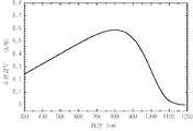
RGB표색계에서는 파장 700nm의 광의 원색 「R」, 파장 546.1nm의 광의 원색 「G」, 파장 435.8nm의 광의 원색 「B」로 하여 RGB 3원색을 정의하여도 좋다. 단 레이저 프로젝터와 같은 특수한 표시장치 이외의 많은 표시장치에서는 그와 같은 고정된 파장을 표시하는 것이 곤란함으로 특정의 파장강도분포를 가진 것으로서 「R」, 「G」 및 「B」를 선정설정 또는 정의하여도 좋다.In the RGB colorimetric system, three primary colors of RGB may be defined as primary colors "R" of light having a wavelength of 700 nm, primary colors "G" of light having a wavelength of 546.1 nm, and primary colors "B" of light having a wavelength of 435.8 nm. However, it is difficult to display such a fixed wavelength in many display devices other than a special display device such as a laser projector, so that it is possible to select "R", "G" and "B" .
즉 「R」, 「G」 및 「B」라는 표현은 각각 특정의 일파장의 원색 또는 단색을 나타내는 경우만이 아닌 특정의 파장강도를 가진 보기에 「R」, 「G」 및 「B」의 3원색에 각각 근사한 원색 또는 단색을 나타내는 경우가 있다.That is, the expressions of "R", "G", and "B" are not limited to the case of representing a single primary color or single color of a specific wavelength, There may be cases in which primary colors or primary colors approximate each other.
또한 일반에서 사람의 시세포인 추태세포에는 중심파장 564nm정도로 파장범위 400nm정도부터 680nm정도의 적색파장영역 또는 「R파장영역」에 감도가 있는 세포, 중심파장 534nm정도로 파장범위 400nm정도부터 650nm정도의 녹색파장영역 또는 「G파장영역」에 감도를 가진 세포 및 중심 20nm정도로 파장범위 370nm정도부터 530nm정도의 청색파장영역 또는 「B파장영역」에 감도를 가진 세포의 3종류가 있다고 한다.In general, in human psychedelic subtracted cells, cells having a wavelength in the range of about 400 nm to 680 nm or a wavelength in the "R wavelength region" of about 564 nm in the central wavelength, cells having a wavelength in the range of about 400 nm to about 650 nm There are three types of cells having a sensitivity in a wavelength region or a " G wavelength region ", and cells having a sensitivity in a blue wavelength region or a " B wavelength region " with a center wavelength of about 370 nm to about 530 nm.
그리고 사람은 그러한 3종류의 세포에 의해 각각 「R」, 「G」 및 「B」에 대응하는 색을 시각한다고 한다. 또한 이러한 파장범위에는 개인차가 있기 때문에 엄밀한 정의는 곤란하다.And a person views the color corresponding to "R", "G" and "B" by such three types of cells, respectively. In addition, strict definition is difficult because there are individual differences in the wavelength range.
또한 피사체로부터의 가시광선을 색글래스 필터 등에 의해 「R파장영역」, 「G파장영역」 및 「B파장영역」으로 분리하여 각각의 파장영역에 의한 화상을 촬상한다.Further, visible light rays from a subject are separated into "R wavelength region", "G wavelength region" and "B wavelength region" by a color glass filter or the like, and an image by each wavelength region is captured.
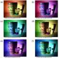
그리고 「R파장영역」에 의한 화상의 명도를 「R」로 「G파장영역」에 의한 화상의 명도를 「G」로 「B파장영역」에 의한 화상의 명도를 「B」에 의해 표색하며 그들 3개의 표색된 화상을 광의 3원색을 겹쳐 표시하는 말하자면 가법혼색에 의해 컬러화상으로서 표색되어 표시되어도 좋다.The brightness of the image by the R wavelength region is represented by R, the brightness of the image by the G wavelength region is represented by G, and the brightness of the image by the B wavelength region is represented by B, The three colored images may be displayed as a color image by displaying the three primary colors of light superimposed on each other.
또한 「C」(Cyan), 「M」(Magenta) 및 「Y」(Yellow)를 3원색으로서 컬러표시하는 CMY컬러 표시를 행하는 것도 가능하다. 이것은 특정의 색 농도를 가진 잉크 등을 흰색의 종이 등에 도포하여 화상의 명도를 표현하는 경우 잘 이용되어 광을 막는 형태로 색을 혼합하기 때문에 감법혼색이라고 불리운다.It is also possible to perform CMY color display in which "C" (Cyan), "M" (Magenta) and "Y" (Yellow) This is called subtractive color mixing because it mixes colors in a form that is well used and blocks light when an ink or the like having a specific color density is applied to white paper or the like to express brightness of an image.
또한 RGB컬러 표시 혹은 CMY컬러표시에 B(Black)를 추가하여RGBB컬러표시 혹은 CMYBk(key), 또는 , CMYK(Key)컬러표시 등도 이용하는 것이 바람직하다.It is also preferable to use RGBB color display or CMYBk (key) or CMYK (Key) color display by adding B (Black) to RGB color display or CMY color display.
또한 본 발명의 각 측면에 있어서도 표색이란 가시광선하에 있어서의 화상의 명도 또는 특정의 물리량의 면내강도분포를 색의 명도로 표시하는 것이다.Also in each aspect of the present invention, the color of the image means the brightness of the image under visible light or the in-plane intensity distribution of a specific physical quantity in terms of color brightness.
단 상술과 같이 원색 또는 단색에 의해 표색하는 경우나 컬러화상 혹은 컬러표시를 위해 가법혼색 및 감법혼색에 의해 복색으로 표색하는 경우가 있다.However, in the case of coloring by primary color or monochromatic color as in the above-described case, or by adding color mixture or subtractive color mixture for color image or color display, there is a case of coloring with a doubled color.
더욱이 원색 또는 단색은 특정의 일파장에서 만들어지는 경우나 특정의 파장강도분포를 가진 경우가 있다.Furthermore, primary colors or monochromatic colors may be produced at a specific wavelength or may have a specific wavelength intensity distribution.
또한 적외선이란 사람의 눈의 감도의 국제표준인 비시감도곡선에 의하면 750nm정도 이상의 사람의 눈에 보이지 않는 파장의 광 혹은 전자파로 하는 것도 가능하다. 단 사람의 눈의 파장감도는 개인차가 있으므로 엄밀한 선긋기는 곤란하며 경우에 따라 전기 파장은 변동할 수 있다.In addition, according to the Vishi sensitivity curve, which is an international standard for the sensitivity of an eye of an infant, it is also possible to use an optical wave or an electromagnetic wave of wavelengths not visible to a person of about 750 nm or more. However, since there is individual variation in the wavelength sensitivity of the human eye, it is difficult to strictly draw a line, and the electric wavelength may fluctuate in some cases.
또한 적외선은 보통 사람의 눈에 보이지 않는 불가시광선으로 불리운다.Infrared rays are also called invisible rays that are invisible to ordinary people.
단 적외선의 범주에 속하는 광이라 해도 강도가 매우 강한 경우는 사람에 따라 보이는 경우도 있다.Even if it belongs to the category of infrared rays, the intensity is very strong.
또한 「R」 또는 「R파장영역」을 중심파장 640nm정도의 색 내지는 광이여도 좋고 「G」 또는 「G파장영역」을 중심파장 530nm정도의 색 내지는 광이여도 좋으며 「B」 또는 「B파장영역」을 중심 35nm정도의 색 내지는 광 등이어도 좋다.Further, "R" or "R wavelength region" may be a color or light having a center wavelength of about 640 nm, "G" or "G wavelength region" may be a color or light having a center wavelength of about 530 nm, and "B" Region " may be a color or light of about 35 nm in the center.
또한 「R」 또는 「R파장영역」을 파장범위 625nm에서 740nm정도의 색 내지는 광이라 해도 좋으며 「G」 또는 「G파장영역」을 파장범위 500nm에서 565nm정도의 색 내지는 광이라 해도 좋으며 「B」 또는 「B파장영역」을 파장범위 450nm에서 485nm정도의 색 내지는 광이라 해도 좋다.The " R " or " R wavelength region " may be a color or light having a wavelength in the range of 625 nm to 740 nm and a " G " or " G wavelength region " may be a color or light in a wavelength range of 500 nm to 565 nm. Or the " B wavelength region " may be a color or light of about 485 nm in the wavelength range of 450 nm.
또한 「R」 또는 「R파장영역」을 파장범위 570nm에서 750nm정도의 색 내지는 광이라 해도 좋으며 「G」 또는 「G파장영역」을 파장범위 480nm에서 570nm정도의 색 내지는 광이라 해도 좋으며 「B」 또는 「B파장범위」를 파장범위 400nm에서 480nm정도의 색 내지는 광이라 해도 좋다.The " R " or " R wavelength region " may be a color or light having a wavelength range of about 570 nm to about 750 nm, and the " G " or " G wavelength region " may be a color or light having a wavelength range of about 480 nm to about 570 nm. Or " B wavelength range " may be a color or light having a wavelength range of 400 nm to 480 nm.
이와 같이 「R」, 「G」, 「B」, 「R파장영역」, 「G파장영역」 및 「B파장영역」의 엄밀한 구별은 곤란하며 경우에 따라 변동하고 중복되는 정도도 변동될 수 있다. 광과 광선은 같은 것을 의미한다.Thus, it is difficult to strictly distinguish between "R", "G", "B", "R wavelength region", "G wavelength region" and "B wavelength region" Light and rays mean the same thing.
또한 본 발명의 다른 측면으로서 상기의 어떤 측면에 있어서, 한층 더 전기 조사부는, 한층 더 전기 틀린 파장강도분포를 가진 적외선을 LED(발광다이오드) 또는 적외선LED 및 LD(레이저다이오드) 또는 적외선 LD의 어느 하나 또는 복수가 방사하는 적외선에 의해 발생하는 구성을 개시한다.According to another aspect of the present invention, in an aspect of the present invention, the electric irradiation unit is further provided with an infrared ray emitting diode (LED), an infrared LED, an LD (laser diode) A configuration in which one or a plurality of rays are generated by infrared rays emitted is disclosed.
또한 본 발명의 한층 더 다른 측면으로서 상기 어떠한 측면에 있어서 한층 더 전기 촬상부는 CCD(Charge Coupled Device) 이미지센서 또는 CMOS(Complementary Metal Organic Semiconductor) 이미지센서 또는 APD(Avalanche Photodiode) 이미지센서 등의 고체촬상소자 또는 이미지디섹터 또는 아이코노스코프 또는 이미지오르시콘 또는 비지콘 또는 서치콘 또는 프랜비콘 또는 뉴비콘 또는 뉴코스콘 또는 카르니콘 또는 토리니콘 또는 HARP(High-gain Avalanche Rushing amorphous Photoconductor) 또는 자기포커스형 이미지 인텐시파이어 또는 마이크로채널 플레이트 등의 촬상관 또는 촬상판 또는 MEMS(Micro Electro Mechanical System) 보로미터 등의 보로미터계 촬영소자 또는 집뢰계 촬영소자 등에 의한 구성을 개시한다.In still another aspect of the present invention, the electronic image sensing unit further includes a solid-state image sensor (CCD) such as a CCD (Charge Coupled Device) image sensor, a CMOS (Complementary Metal Organic Semiconductor) image sensor, or an APD (Avalanche Photodiode) Or an image disector or an iconoscopic or image orthicon or a beacon or search cone or a frenic beacon or a new beacon or a nucoscone or a carnicon or a toricone or a high-gain avalanche rushing amorphous photoconductor (HARP) An image pickup tube such as a fire or microchannel plate Or a borometry photographing element such as an image pickup plate or a MEMS (Micro Electro Mechanical System) borometer, or a light emitting element photographing element.
촬영소자는 Si 또는 Ge 등의 단원소계 또는 SiGe 또는 InAs 또는 InSb 또는 PbS 또는 PbSe 또는 InGaAs 또는 HgCdTe 등 화합물계를 이용한 고체촬상소자 등에 의한 구성되는 것이 바람직하다.The image pickup element is preferably composed of a solid-state image pickup element using a compound system such as Si or Ge, SiGe, InAs, InSb, PbS, PbSe, InGaAs or HgCdTe.
또한 본 발명의 한층 더 다른 측면으로서 상기 어떤 측면에 있어서 한층 더 전기 촬상부는 렌즈, 조리개, 필터 등에 의한 구성을 개시한다.In still another aspect of the present invention, in any of the above aspects, the electric imaging unit further includes a lens, a diaphragm, a filter, and the like.
또한 표색설정이란 화상을 표시할 때 화상의 명도를 어떠한 색에 의해 표색 할까를 사전에 설정하여 두는 것이며, 표색설정은 예를 들어 화상정보 또는 화상신호의 전송의 타이밍을 설정하는 것이라든지 기준 트리커에 축차적으로 화상정보 또는 화상신호를 대응시킴으로 설정할 수 있다.In addition, the color setting is to set in advance which color the image brightness should be colored when displaying an image, and the color setting may be set, for example, to set the timing of transmission of image information or an image signal, To correspond to the image information or the image signal in a sequential manner.
또한 표색정보 또는 표색설정신호를 별도 생성함으로 설정할 수 있음과 화상정보 또는 화상신호에 표색정보 또는 표색설정신호를 첩중시킴으로 설정할 수 있음과 메모리에 있어서 번지로 설정할 수 있음과 신호처리에 있어서 라벨 붙임 및 블랙 붙임에 의해 설정할 수 있는 등에 의해 행할 수도 있다.In addition, it can be set by separately generating color information or color specification signal, and it can be set by superimposing color information or color specification signal on image information or image signal, and can be set as address in memory, labeling in signal processing, Or may be set by black sticking or the like.
또한 본 발명은 또 다른 측면으로서 조사부, 촬상부, 표색설정부 및 제어처리부를 갖추고 전기 촬상부는 촬상동작신호를 전기 제어처리부에 보내고 전기 제어처리부는 전기 촬상동작개시신호를 전기 제어처리부에 보내며 전기 제어처리부는 전기 촬상동작 개시신호를 기준으로 조사동작 개시지시신호를 전기 조사부에 보내고 더욱이 한층 더 표색설정 동작개시지시신호를 전기 표색 설정부에 보내고 전기 조사부는 전기 조사동작 개시지시신호를 기준으로 다른 파장강도분포를 가진 적외선을 피사체에 조사하며 전기 촬상부는 상기 전기 피사체에 의해 반사된 다른 파장강도분포를 가진 적외선을 피사체에 조사하며 전기 촬상부는 전기 피사체에 의해 반사된 다른 강도분포를 가진 각각의 적외선 적외선에 의한 전기 피사체의 화상을 촬상하여 각각의 화상을 나타내는 화상정보를 형성하여 전기 표색설정부에 보내며 전기 표색설정부는 전기 표색설정 동작개시지시신호를 기준으로 전기 형성된 화상정보가 나타내는 화상의 각각을 단색에 의해 표색하기 위한 표색정보를 전기 화상정보에 설정하는 것을 특징으로 하는 화상촬영장치를 개시한다.According to another aspect of the present invention, there is provided a still further aspect of the present invention, which includes a radiation section, an image pickup section, a color setting section, and a control processing section, wherein the electric image pickup section sends an image pickup operation signal to an electric control processing section, The processing section sends an irradiation operation start instruction signal to the electric irradiation section based on the electric imaging operation start signal and further sends a coloring operation start instruction signal to the electric coloring setting section, And the electric imaging unit irradiates the subject with infrared rays having different wavelength intensity distributions reflected by the electric subject, and the electric imaging unit irradiates the subject with infrared rays having different intensity distributions reflected by the electric subject, Capturing an image of an electric subject by the camera And the electric-color-signal setting unit sets the color-related information for coloring each of the images represented by the electro-formed image information on the basis of the electric-color- Is set to the image capturing device.
또한 본 발명의 각 측면에 있어서 정보란 사물이나 사물의 내용 또는 모습 및 그것을 알리는 것이며, 정보는 신호에 의해 전달되는 것이 바람직하다. 그를 위해 정보와 신호는 같은 것을 의미하는 경우도 있다.Further, in each aspect of the present invention, the information is the content or appearance of an object or thing and the information or the like, and the information is preferably transmitted by a signal. For that, information and signal may mean the same thing.
또한 본 발명의 또 다른 측면으로서 조사부, 촬상부, 표색설정부 및 제어처리부를 갖추고 전기 제어처리부는 조사동작개시 지시신호를 전기 조사부에 보내 한층 더 촬상동작 개시 처리신호를 전기 촬상부에 보내 한층 더 표색설정 동작개시 신호를 전기 표색설정부에 보내 전기 조사부는 전기 조사동작 개시신호를 바탕으로 다른 파장 강도분포를 갖는 적외선을 피사체에 조사하여 전기 촬상부는 전기 촬상동작 개시신호를 바탕으로 전기 피사체에 의해 반사된 다른 강도분포를 가지는 각각의 적외선에 의한 전기 피사체의 화상을 촬상하여 각각의 적외선에 의한 전기 피사체의 화상을 촬상하여 각각의 화상을 나타내는 화상정보를 형성하여 전기 표색설정부에 보내며 전기 표색설정부는 전기 표색설정 동작개시 지시신호를 바탕으로 전기 형성된 화상정보가 나타내는 화상의 각각을 다른 단색에 의해 표색하기 위한 표색정보를 전기 화상정보에 설정하는 것을 특징으로 하는 화상촬영장치를 개시한다.Further, as another aspect of the present invention, the electronic control unit includes an irradiation unit, an imaging unit, a color setting unit, and a control processing unit. The electronic control unit sends an irradiation operation start instruction signal to the electric irradiation unit, The colorimetry setting operation start signal is sent to the electric coloring setting unit. The electric irradiation unit irradiates the subject with infrared rays having different wavelength intensity distributions based on the electric irradiation operation start signal, and the electric imaging unit generates electric signals based on the electric imaging operation start signal Capturing an image of an electric subject by each infrared ray having a different reflected intensity distribution, capturing an image of an electric subject by each infrared ray, forming image information representing each image, sending the image information to the electric coloring setting unit, Based on the electric-color specification setting operation start instruction signal, And sets colorimetric information for coloring each of the images represented by the information with different monochromatic colors in the electric image information.
또한 본 발명의 또 다른 측면으로서 한층 더 조사부, 촬상부, 표색설정 및 제어처리부를 갖추고 전기 조사부는 조사동작 개시신호를 제어처리부에 보내 한층 더 다른 파장강도를 가지는 적외선을 피사체에 조사하고, 전기 제어처리부는 전기 조사동작 개시신호를 바탕으로 촬상동작 개시신호를 전기 촬상부에 보내 한층 더 표색 설정동작 개시신호를 전기 표색설정부에 보내 한층 더 다른 파장강도분포를 가진 적외선을 가진 적외선을 피사체에 조사하며 전기 제어처리부는 전기 조사동작개시신호를 시작으로 촬상동작 개시신호를 전기 촬상부로 보내고 더욱이 표색설정동작개시신호를 전기 표색설정부로 보내며 전기 촬상부는 전기 피사체에 의해 반사된 다른 파장강도를 가진 각각의 적외선에 의한 전기 피사체의 화상을 촬상하여 각각의 화상을 나타내는 화상정보를 형성하여 전기 표색설정부에 보내며 전기 표색설정부는 전기 표색설정 동작개시지시신호를 시작으로 전기 형성된 화상정보가 나타내는 화상 각각을 다른 단색에 의해 표색하기 위한 표색정보를 전기 화상정보에 설정하는 것을 특징으로 하는 화상촬영장치를 개시한다.Further, as another aspect of the present invention, the electric irradiation unit further includes an irradiation unit, an imaging unit, a color setting and a control processing unit, and sends an irradiation operation start signal to the control processing unit to irradiate infrared rays having yet another different wavelength intensity to the subject, The processing section sends an image pickup operation start signal to the electric image pickup section based on the electric irradiation operation start signal, sends another color image forming operation start signal to the electric color specification setting section, and irradiates the infrared ray having infrared ray having yet another wavelength intensity distribution to the subject And the electric control processing section sends an image pickup operation start signal to the electric image pickup section starting from the electric irradiation operation start signal and further sends a colorimetric setting operation start signal to the electric coloring setting section, An image of an electric subject by infrared rays is picked up, And the electric color specification setting section sets the coloring information for coloring each of the images represented by the image information formed electrically with the other monochromatic color to the electric image information The image capturing apparatus comprising:
또한 본 발명의 또 다른 측면으로는, 한층 더 조사부, 촬상부, 표색설정부 및 제어처리부를 갖추고, 전기 표색설정부는 표색설정동작개시신호를 전기 제어처리부에 보내고 전기 제어처리부는 전기 표색설정동작개시신호를 시작으로 조사동작개시지시신호를 전기 촬상부에 보내며 전기 조사부는 전기 조사동작개시신호를 시작으로 다른 파장강도분포를 갖는 적외선을 피사체에 조사하며 전기 촬상부는 전기 촬상동작개시신호를 시작으로 전기 피사체에 의한 반사되는 다른 파장강도를 갖는 각각의 적외선에 의한 전기 피사체의 화상을 촬상하여 각각의 화상을 나타내는 화상정보를 형성하여 전기 표색설정부에 보내 전기 형성된 화상정보가 나타내는 화상의 각각을 다른 단색에 의해 표색하기 위한 표색정보를 전기 화상정보에 설정하는 것을 특징으로 하는 화상촬상장치를 개시한다.Further, according to another aspect of the present invention, there is provided an image processing apparatus including: an illumination unit, an image pickup unit, a coloring setting unit, and a control processing unit; the electric coloring setting unit sends a coloring setting operation start signal to the electric control processing unit; Signal to the electric imaging unit, the electric irradiation unit irradiates the subject with infrared rays having different wavelength intensity distributions starting from the electric irradiation operation start signal, and the electric imaging unit starts electric imaging operation starting signal An image of an electric object by infrared rays having different wavelength intensities reflected by a subject is picked up to form image information representing each image and sent to an electric coloring setting unit to convert each of the images represented by the formed image information into another monochrome In the electronic image information, the coloring information for coloring It discloses an image pickup apparatus.
또한 본 발명의 또 다른 측면으로는, 한층 더 조사부, 촬상부, 표색설정부 및 제어처리부를 갖추고, 전기 표색설정부는 표색설정동작개시신호를 전기 제어처리부에 보내고 전기 제어처리부는 전기 표색설정동작개시신호를 시작으로 조사동작개시지시신호를 전기 촬상부에 보내며 전기 조사부는 전기 조사동작개시신호를 시작으로 다른 파장강도분포를 가지는 적외선을 피사체에 조사하며 전기 촬상부는 전기 촬상동작개시신호를 시작으로 전기 피사체에 의한 반사되는 다른 파장강도를 가지는 각각의 적외선에 의한 전기 피사체의 화상을 촬상하여 각각의 화상을 나타내는 화상정보를 형성하여 전기 표색설정부에 보내 전기 형성된 화상정보가 나타내는 화상의 각각을 다른 단색에 의해 표색하기 위한 표색정보를 전기 화상정보에 설정하는 것을 특징으로 하는 화상촬상장치를 개시한다.Further, according to another aspect of the present invention, there is provided an image processing apparatus including: an illumination unit, an image pickup unit, a coloring setting unit, and a control processing unit; the electric coloring setting unit sends a coloring setting operation start signal to the electric control processing unit; Signal to the electric imaging unit, the electric irradiation unit irradiates the subject with infrared rays having different wavelength intensity distributions starting from the electric irradiation operation start signal, and the electric imaging unit starts electric imaging operation starting signal An image of an electric subject by infrared rays having different wavelength intensities reflected by the object is picked up to form image information representing each image and sent to the electric coloring setting unit to convert each of the images represented by the formed image information into another monochrome To set the coloring information for coloring with the electric image information It discloses an image pickup apparatus according to.
또한 본 발명의 또 다른 측면으로서 상기 어느 측면에 있어서 한층 더 표시부를 갖추고 전기 제어처리부는 한층 더 표시동작개시신호를 전기 표시부에 보내고 전기 표시부는 전기 표시동작개시신호를 시작으로 전기 표색정보가 설정된 화상정보가 나타내는 화상의 각각을 전기 표색정보에 따라 표색하여 표시하는 정보를 구성을 개시한다.In still another aspect of the present invention, the electric control unit further includes a display unit on any of the above aspects, and the electric control unit further sends a display operation start signal to the electric display unit, and the electric display unit displays an electric image Information constituting information for displaying each of the images represented by the information in accordance with the electric-color-coding information and displaying it.
또한 본 발명의 또 다른 측면으로서 상기의 어느 측면에 있어서 한층 더 화상보존부를 갖추고 전기 제어처리부는 한층 더 화상보존동작개시신호를 전기 화상보존부에 보내고 전기 화상보존부는 전기 화상보존동작개시지시신호를 기준으로 전기 표색정보가 설정된 화상정보를 보존하는 구성을 개시한다.In still another aspect of the present invention, in any of the aspects described above, the electric control unit further includes an image storage unit, and further the image storage operation start signal is sent to the electric image storage unit, and the electric image storage unit stores the electric image storage operation start instruction signal A configuration for storing image information in which electric-color specification information is set as a reference is described.
또한 본 발명의 또 다른 측면으로서 상기 어느 측면에 있어서 한층 더 전기 화상보존부는 전기 화상보존부에 보존된 전기 표색정보가 설정된 화상정보를 전기 화상보존동작개시지시신호를 기준으로 전기 표색부에 보내고 전기 표색부는 전기 표시동작개시지시신호를 기준으로 전기 표색정보가 설정된 화상정보 및 전기 화상보존부에 보존된 전기 표색정보가 설정된 화상정보의 어느 한쪽 또는 양쪽에 있는 표색정보가 설정된 화상정보의 나타내는 화상을 전기 표색정보에 따라 표색시켜 표시하는 구성을 개시한다.In still another aspect of the present invention, in any of the above aspects, the electric image saving section further sends the image information for which the electric color specification information stored in the electric image storage section is set to the electric ticket coloring section based on the electric image storage operation start instruction signal, The colorimetry section displays the image represented by the image information in which the colorimetric information on either or both of the image information in which the electric coloring information is set and the image information in which the electric coloring information stored in the electric image storage section is set is set on the basis of the electric display operation start instruction signal And displaying the coloring in accordance with the electric coloring information.
본 발명의 다른 측면에 있어서 상기 어느 것의 측면에 있어서 한층 더 분리조사부는 조사동작개시지시신호를 받은 것을, 조사동작개시지시신호를 보낸 측에 전달하는 것이 바람직하다.In another aspect of the present invention, it is preferable that furthermore, on any of the above-described aspects, it is preferable that the separation irradiation section further informs the sending side of the irradiation operation start instruction signal that the irradiation operation start instruction signal has been received.
본 발명의 다른 측면에 있어서 상기 어느 것의 측면에 있어서 한층 더 촬상부는 촬상동작개시지시신호를 받은 것을, 촬상동작개시지시신호를 보낸 측에 전달하는 것이 바람직하다.In another aspect of the present invention, it is preferable that, on any of the above-described side surfaces, the imaging section further informs the receiving side that the imaging operation start instruction signal has been received that the imaging operation start instruction signal has been received.
본 발명의 다른 측면에 있어서 상기 어느 것의 측면에 있어서 한층 더 표색설정부는 표색설정 동작개시 지시신호를 받은 것을, 표색설정 동작개시신호를 보낸 측에 전달하는 것이 바람직하다.In another aspect of the present invention, it is preferable that, on any of the above aspects, the color specification setting section transmits to the sender the color specification setting operation start signal that the color specification setting operation start instruction signal has been received.
본 발명의 다른 측면에 있어서 상기 어느 것의 측면에서 한 층 더 제어처리부는 촬상동작개시신호를 받은 것을 촬상부에 전달하는 것이 바람직하다.In another aspect of the present invention, it is preferable that, in any of the above aspects, the one-layer further control processing unit delivers to the imaging unit the signal that has received the imaging operation start signal.
또한 본 발명의 또 다른 측면에 있어서는 상기 어느 것의 측면에 있어서 한층 더 전기 조사동작개시 지시신호, 전기 촬상동작 개시신호 및 전기 표색설정동작개시 지시신호의 어느 하나 또는 복수를 적외선에 의해 보내는 것이 바람직하다.Further, in still another aspect of the present invention, it is preferable that one or more of the electric irradiation operation start instruction signal, the electric imaging operation start signal, and the electric color specification setting operation start instruction signal is further transmitted by infrared rays on any of the above aspects .
또한 본 발명의 또 다른 측면으로 상기 어떤 측면에 있어서 한층 더 전기 조사동작개시 지시신호, 전기 촬상동작개시 지시신호 및 전기 표색설정동작개시 지시신호의 어느 하나 또는 복수를 적외선으로 보내는 것이 바람직하다.In still another aspect of the present invention, it is preferable to send one or more of the electric irradiation operation start instruction signal, the electric imaging operation start instruction signal, and the electric color specification setting operation start instruction signal to the infrared ray.
또한 본 발명의 또 다른 측면으로 상기 어느 것의 측면에 있어서 한층 더 전기 조사동작개시 지시신호, 전기 촬상동작개시 지시신호 및 전기 표색설정동작개시 지시신호의 어느 하나 또는 복수를 적외선으로 보내는 것이 바람직하다.In still another aspect of the present invention, it is preferable that one or more of the electric irradiation operation start instruction signal, the electric imaging operation start instruction signal, and the electric coloring setting operation start instruction signal are further transmitted by infrared rays on any of the above aspects.
또한 본 발명의 또 다른 측면으로 상기 어느 것의 측면에 있어서, 한층 더 전기 조사동작개시 지시신호, 전기 촬상동작개시 지시신호 및 전기 표색설정동작개시 지시신호의 어느 하나 또는 복수를 적외선으로 보내는 것이 바람직하다.Further, in any of the above aspects of the present invention, it is preferable that one or more of the electric irradiation operation start instruction signal, the electric imaging operation start instruction signal, and the electric color specification setting operation start instruction signal is further transmitted by infrared rays .
또한 본 발명의 또 다른 측면으로 상기 어느 것의 측면에 있어서, 한층 더 전기 표시동작개시 지시신호 및 화상보존동작개시 지시신호의 어느 하나 또는 복수를 적외선에 의해 보내는 구성을 개시한다.According to another aspect of the present invention, there is provided a configuration for transmitting either one or more of an electric display operation start instruction signal and an image storage operation start instruction signal by infrared rays.
또한 본 발명의 또 다른 측면으로 상기 어느 것의 측면에 있어서 한층 더 각 종 동작개시신호 및 각종 동작개시지시신호의 어느 것 또는 복수를 무선에 의해 보내는 것이 바람직하다.Further, as another aspect of the present invention, it is preferable that one or more of the various operation start signals and the various operation start instruction signals are further transmitted by radio in any of the above aspects.
또한 본 발명의 또 다른 측면으로 상기 어느 것의 측면에서 한층 더 전기 조사부는 전기 조사동작 개시신호를 전기 다른 파장강도 분포를 가지는 적외선의 어느 하나 또는 복수에 중첩시키는 것이 바람직하다.According to another aspect of the present invention, in any of the above aspects, it is preferable that the electric irradiation unit further superimposes the electric irradiation operation start signal on one or a plurality of infrared rays having different wavelength intensity distributions.
또한 본 발명의 또 다른 측면으로는 전기 어느 것의 측면에 있어서 한층 더 전기 촬상부는, 한층 더 파장검출부를 갖추고, 전기 파장검출부는, 전기 다른 파장강도분포를 가지는 적외선의 어느 하나 또는 복수의 파장 및 또는 전기 피사체에 의해 반사된 다른 파장강도분포를 가지는 각각의 적외선의 어느 하나 또는 복수의 파장을 계측하여 전기 조사부의 동작의 상태를 검출하는 것이 바람직하다.According to still another aspect of the present invention, there is provided an electronic still further comprising a wavelength detecting portion, wherein the electric wave detecting portion is configured to detect any one or a plurality of wavelengths of infrared rays having different wavelength intensity distributions and / It is preferable to detect one or a plurality of wavelengths of each infrared ray having different wavelength intensity distributions reflected by the electric object to detect the state of operation of the electric irradiation unit.
또한 본 발명의 또 다른 측면으로는 상기 어느 것의 측면에서 전기 촬상부는 한층 더 정보생성부를 갖추어 전기 촬상동작개시신호 및 전기 화상정보에서 컴포지트 및 컴퍼넨트 신호를 생성하는 것이 바람직하다.In still another aspect of the present invention, it is preferable that the electronic imaging unit further includes an information generating unit to generate a composite and component signal from the electrical imaging operation start signal and the electrical image information.
또한 본 발명의 또 다른 측면으로는 상기 어는 것의 측면에서 전기 제어처리부는 한층 더 정보분리부를 갖추어 전기 컴퍼지트 신호 및 컴퍼넨트 신호를 전기 촬상동작개시 지시신호 및 전기 화상정보의 어느 하나 또는 복수에 분리하는 것이 바람직하다.According to another aspect of the present invention, in the aspect of the present invention, the electrical control processing section further includes an information separating section for separating the electrical composite signal and the component signal into one or a plurality of electrical imaging operation start instruction signals and electrical image information .
또한 컴퍼넨트 신호는 화상을 구성하는 휘도신호, 동기신호, 색신호를 각각 분리하여 취급하게끔 한 영상신호 또는 화상정보이며 컴퍼지트 신호는 화상을 구성하는 휘도신호, 색 신호, 동기신호를 구성하여 신호선 1개로도 취급할 수 있도록 한 복합동기 신호 또는 화상정보이다.The composite signal is a video signal or image information for separately handling a luminance signal, a synchronizing signal, and a color signal constituting an image, and the composite signal constitutes a luminance signal, a color signal, and a synchronizing signal constituting an image, And the composite synchronizing signal or the image information so as to be able to be handled as an opening.
또한 본 발명의 또 다른 측면으로 상기 어떠한 측면에 있어서, 한층 더 화상변환부를 갖추고 전기 화상변환부는 전기 표색정보가 설정된 화상정보 및 전기 화상보존부를 갖추어 전기 화상보존부에 보존된 전기 표색정보가 설정된 화상정보의 어느 하나 또는 복수에 가산, 감산, 승산 및 제산의 어느 하나의 사칙연산, 지수관수, 대수관수 및 임의관수의 어느 하나 또는 복수를 이용한 연산을 적용하여 변환된 화상정보 또는 화상을 형성하는 구성을 개시한다.According to another aspect of the present invention, there is provided a still further aspect of the present invention, in which the electric image conversion section further comprises image conversion section and image information and electric image storage section in which electric coloring information is set, A configuration for forming the converted image information or image by applying an arithmetic operation using any one or more of an arithmetic operation, an arithmetic operation, an exponent function, an algebra function, and an arbitrary manipulation of any one of addition, subtraction, .
또한 본 발명의 또 다른 측면으로서 상기의 어느 측면에 있어서 한층 더 전기 촬상부는 촬상동작개시신호를 생성하여 한층 더 정보생성부를 갖추어 한층 더 전기 정보생성부는 전기 촬상동작개시신호 및 전기 화상정보를 분리가능하게 합성된 합성정보를 생성하는 구성을 개시한다.In still another aspect of the present invention, in any of the aspects described above, the electric-image pickup section further generates an image-pickup operation start signal to further include an information generating section, and further, the electric-information generating section separates the electric- And generating synthesis information synthesized by the synthesis means.
또한 본 발명의 또 다른 측면으로서 상기 어느 측면에 있어서 전기 제어처리부는 한층 더 정보분리부를 갖추어 전기 정보분리부는 전기 합성정보로부터 전기 촬상동작개시신호 및 전기 화상정보의 어느 하나 또는 복수를 분리하는 구성을 개시한다.In still another aspect of the present invention, in any of the above aspects, the electric control processing section further includes an information separating section, and the electric information separating section separates one or more of the electric imaging operation start signal and the electric image information from the electric combination information .
또한 본 발명의 또 다른 측면으로서 상기 어느 측면에 있어서 한층 더 전기 표색설정부는 전기 형성된 화상정보가 나타내는 화상 중 파장범위 또는 중심파장이 가장 단파장 측에 있는 파장강도분포를 가지는 적외선에 의해 촬상된 제1화상을 「R」에 의해 표색하기 위한 표색정보를 전기 제1화상 이외의 전기 촬상된 화상을 전기 「R」 이외에 의해 표색하기 위한 표색정보를 전기 제1화상을 나타내는 화상정보에 설정하는 구성을 개시한다.In still another aspect of the present invention, in any of the aspects described above, the electric-color-signal-setting unit further includes an electric-color-signal setting unit that sets the electric-color- The colorimetric information for coloring the image by " R " is set to the image information representing the first electrical image, and the colorimetric information for coloring the electrically photographed image other than the first electrical image by electrical characters other than the electrical " R & do.
또한 본 발명의 또 다른 측면으로서 분리부, 촬상부 및 표색설정부를 갖추고 전기 분리부는 피사체로부터의 광선을 다른 파장강도분포를 가진 적외선에 분리하고 전기 촬상부는 각각의 전기 적외선에 의해 전기 피사체의 화상을 촬상하여 화상정보를 구성하며 전기 표색설정부는 전기 촬상된 화상 중 파장범위 또는 중심파장이 가장 단파장측에 있는 파장강도분포를 가진 적외선에 의해 촬상된 제1화상을 「R」에 의해 표색시키기 위한 표색정보를 전기 제1화상을 나타내는 화상 이외의 전기 촬상된 화상을 전기 「R」 이외에 의해 표색시키기 위한 표색정보를 전기 제1화상정보를 나타내는 화상정보 이외의 전기 형성된 화상정보에 설정하는 것을 특징으로 하는 화상촬상장치를 개시한다.In another aspect of the present invention, there is provided a separation unit, an image pickup unit, and a color setting unit, wherein the electric separation unit separates the light rays from the subject into infrared rays having different wavelength intensity distributions, and the electric image sensing unit picks up an image of the electric subject And the electric-color-signal setting unit sets the first color image for coloring the first image picked up by the infrared ray having the wavelength range of the wavelength or the wavelength of the shortest wavelength of the central wavelength among the electro- Color information for coloring the electrically photographed image other than the image representing the first electrical image by electrical characters other than electrical " R " is set to electrically formed image information other than the image information representing the first electrical image information An image pickup apparatus is disclosed.
또한 본 발명의 또 다른 측면으로서 상기의 어느 측면에 있어서 전기 표색설정부는 전기 촬상된 화상 중 파장범위 또는 중심파장이 가장 단파장측에 있는 파장강도분포를 가지는 제1적외선에 의해 촬상된 제1화상을 「R」에 의해 표색하기 위한 표색정보를 전기 제1화상을 나타내는 화상정보에 설정하여 파장범위 또는 중심파장이 전기 제1적외선의 다음의 단파장측에 있는 파장강도분포를 가진 적외선에 의해 촬상된 제2화상을 「G」에 의해 표색하기 위한 표색정보를 전기 제2화상을 나타내는 화상정보에 설정하여 전기 제1화상 및 전기 제2화상 이외의 전기 촬상된 제3화상을 「B」에 의해 표색하기 위한 표색정보를 전기 제3화상을 나타내는 화상정보에 설정하는 것을 특징으로 하는 화상촬영장치를 개시한다.According to another aspect of the present invention, in any of the aspects described above, the electric-color-signal setting unit sets a first image captured by a first infrared ray having a wavelength range or a wavelength intensity distribution whose center wavelength is the shortest wavelength side among the electric- The colorimetric information for coloring by " R " is set to the image information representing the first electrical image, and the colorimetric information for the first image picked up by the infrared ray having the wavelength range or the wavelength of the central wavelength at the next short wavelength side of the first infrared Colorimetric information for coloring two images by " G " is set to image information representing an electrical second image, and a third image electrically photographed other than the electrical first image and the electrical second image is colored by " B & And sets the color specification information for the second image to the image information representing the third electrical image.
또한 본 발명의 또 다른 측면으로서 분리부, 촬상부 및 표색설정부를 갖추고 피사체로부터의 광선을 다른 파장분포를 가지는 광선으로 분리하고 전기 촬상부는 각각의 전기 다른 파장강도를 가지는 광선에 의해 전기 피사체의 화상을 촬상하여 화상정보를 형성하여 전기 표색설정부는 전기 촬상된 화상 중 「R파장영역」을 가진 가시광선 및 전기 「R파장영역」에 가장 가까운 파장강도분포를 가진 적외선에 의해 촬상된 제1화상을 「R」에 의해 표색하기 위한 표색정보를 전기 제1화상을 나타내는 화상정보에 설정하여 전기 제1화상 이외의 전기 촬상된 화상을 전기 「R」 이외에 의한 표색을 하기 위한 표색정보를 전기 제1화상을 나타내는 화상정보 이외의 전기 형성된 화상정보에 설정하는 것을 특징으로 하는 화상촬상장치를 개시한다.Further, according to another aspect of the present invention, there is provided an imaging apparatus including a separation unit, an imaging unit, and a color specification setting unit, wherein light rays from a subject are separated into light beams having different wavelength distributions, And the electric color specification setting unit sets the first image captured by the infrared ray having the wavelength intensity distribution closest to the visible light ray having the "R wavelength range" and the electric "R wavelength range" among the electrically picked-up images The color specification information for coloring by "R" is set to the image information representing the first electrical image, and the colorimetric information for coloring the electrically photographed image other than the first electrical image by the electric "R" To image information other than the image information representing the image information.
또한 본 발명의 또 다른 측면으로 상기 어느 측면에 있어서 전기 표색설정부는 전기 촬상된 화상 중 「R파장영역」을 가진 가시광선 및 전기 「R파장영역」에 가장 가까운 파장강도분포를 가진 제1적외선에 의해 촬상된 제1화상을 「R」에 의해 표색하기 위한 표색정보를 제1화상을 나타내는 화상정보를 설정하여 「G파장영역」을 가지는 가시광선 및 전기 제1적외선에 가장 근접한 파장강도분포를 가진 적외선에 의해 촬상된 제2화상을 「G」에 의해 표색하기 위한 표색정보를 전기 제2화상을 나타내는 화상정보에 설정하여 전기 제1화상 및 전기 제2화상 이외의 전기 촬상된 제3화상을 「B」에 의해 표색하기 위한 표색정보를 전기 제3화상을 나타내는 화상정보에 설정하는 것을 특징으로 하는 화상촬영장치를 개시한다.According to still another aspect of the present invention, in any of the aspects described above, the electric-color-signal setting unit sets the electric signal to the first infrared ray having a wavelength intensity distribution closest to the visible light having the " R wavelength region & Color image by setting the image information representing the first image to the visible light having the " G wavelength region " The colorimetric information for coloring the second image picked up by the infrared rays with "G" is set to the image information indicating the second electric image so that the electric images other than the electric first image and the electric second image are referred to as " B " is set to the image information representing the third electrical image.
또한 본 발명의 또 다른 측면으로 상기 어느 측면에 있어서 한층 더 전기 제1화상을 「R」로 표색하고 제2화상을 「B」로 표색하며 제3화상을 「G」로 표색하는 것이 바람직하다.In still another aspect of the present invention, it is preferable that, in any of the above aspects, the first electrical image is represented by "R", the second image by "B", and the third image by "G".
또한 본 발명의 또 다른 측면으로 상기 어느 것의 측면에 있어서 한층 더 전기 제1화상을 「G」로 표색하고 제2화상을 「B」로 표색하며 제3화상을 「R」로 표색하여도 좋다.In still another aspect of the present invention, in any of the above aspects, the first electrical image may be represented by "G", the second image by "B", and the third image by "R".
또한 본 발명의 또 다른 측면으로 상기 어느 측면에 있어서 한층 더 전기 제1화상을 「G」로 표색하고 제2화상을 「R」로 표색하며 제3화상을 「B」로 표색하여도 좋다.Further, according to still another aspect of the present invention, in any of the above aspects, the first electrical image may be represented by "G", the second image by "R", and the third image by "B".
또한 본 발명의 또 다른 측면으로서 상기 어느 측면에 있어서 한층 더 전기 제1화상을 「B」로 표색하고 제2화상을 「R」로 표색하며 제3화상을 「G」로 표색하여도 좋다.Further, as another aspect of the present invention, in any of the above aspects, the first electrical image may be represented by "B", the second image may be represented by "R", and the third image may be represented by "G".
또한 본 발명의 또 다른 측면으로서 상기 어느 측면에 있어서 한층 더 전기 제1화상을 「B」로 표색하고 제2화상을 「G」로 표색하며 제3화상을 「R」로 표색하여도 좋다.In still another aspect of the present invention, in any of the above aspects, the first electrical image may be represented by "B", the second image by "G", and the third image by "R".
또한 본 발명의 또 다른 측면으로서 상기 어느 측면에 있어서 한층 더 전기 소정의 컬러를 「R」, 「G」 및 「B」의 단색 또는 원색의 어느 것 또는 복수 또는 적당하게 다른 단색 또는 원색 한층 더 그것들의 조합하는 것이 바람직하다.In still another aspect of the present invention, in any of the above aspects, the predetermined color may be any of monochromatic or primary colors of "R", "G", and "B" Is preferable.
또한 본 발명의 또 다른 측면으로 상기 어느 측면에 있어서 한층 더 전기 분리부를 다른 투과파장 강도분포 또는 다른 반사파장 강도분포를 가진 하나 또는 복수의 밴드패스필터 또는 복수의 다이크로익플레이트 필터 하나 또는 복수의 다이크로익프리즘의 어느 하나 또는 복수 등을 이용하여 구성하는 것이 바람직하다.According to another aspect of the present invention, there is provided a method of manufacturing a semiconductor device, comprising: providing a plurality of dichroic filter elements each having a different transmission wavelength intensity distribution or a different reflected wavelength intensity distribution; It is preferable to use any one or a plurality of dichroic prisms.
또한 다이크로익프리즘에 의해 구성된 3판용 필터로는 세개의 프리즘을 갖추어 제1과2 다이크로익프리즘에서 각각 2회의 내면반사로 출사되는 복합프리즘(말하자면 필립스타입의 다이크로익프리즘 같은) 3개의 프리즘을 갖추어 제1 다이크로익프리즘에서 2회의 내면반사로 출사된 제2다이크로익프리즘에서 1회의 내면반사로 출사된 복합프리즘(말하자면 소니타입의 다이크로익프리즘), 세개의 직각삼각주와 하나의 이등변삼각주를 갖춘, 정삼각주상복합프리즘(말하자면 캐스케이드 타입의 다이크로익프리즘), 네개의 직각이등변삼각주를 갖춘 X상의 접합면을 가진 정사각주상 복합프리즘(말하자면 크로스다이크로익프리즘 또는 X큐브), 두개의 삼각추와 두개의 사각추를 갖춘 Z상의 변과 접합면을 가진 3차원의 광로를 가지는 입방체상 복합프리즘(말하자면 Z큐브)등이 있다.The filter for the third plate made up of the dichroic prism also has three prisms and three composite prisms (in other words, a Philips type dichroic prism) emitted from the first and second dichroic prisms each with two inner reflections A composite prism (that is, a Sony type dichroic prism) emitted from the second dichroic prism that is emitted from the first dichroic prism to the inner reflection at the second dichroic prism with one prism, and three right angles and one prism (A croscopic type dichroic prism, that is to say a cascade type dichroic prism) with four isosceles triangles, a quadrangular prism with an X-phase junction with four orthogonal isosceles triangles (ie a cross dichroic prism or X cube) , A cubic-phase composite free-space with a three-dimensional optical path with a Z-phase side and a junction surface with two triangles and two cross- And the like (ie Z cube).
또한 본 발명의 또 다른 측면으로서 상기 어느 측면에 있어서 한 층 더 전기 분리부를 글래스필터, 플라스틱필터, 액정필터 등을 이용하여 구성하는 것이 바람직하다.Further, as another aspect of the present invention, it is preferable that the electrical separating unit in one of the above-described aspects is formed by using a glass filter, a plastic filter, a liquid crystal filter, or the like.
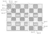
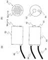
또한 본 발명의 또 다른 측면으로서 상기 어느 측면에 있어서 한 층 더 전기 촬상부는 복수의 화소를 갖추고 전기 분리부는 전기 복수의 화소의 각각에 피착하여 만들어지는 구성을 개시한다.According to still another aspect of the present invention, there is provided a configuration in which the one-layer further electric image pickup section has a plurality of pixels and the electric separation section is made to adhere to each of a plurality of electric pixels.
또한 본 발명의 또 다른 측면으로는 상기 어느 측면에 있어서 한 층 더 전기 밴드패스필터가 렌즈 형상으로 있는 것이 바람직하다.According to another aspect of the present invention, it is preferable that a layer further electric band-pass filter is formed in a lens shape in any of the above aspects.
또한 본 발명의 또 다른 측면으로는 상기 어느 측면에 있어서 한 층 더 전기 다이크로익프리즘필터의 입사구를 렌즈형상으로 하는 것이 바람직하다.According to another aspect of the present invention, in any of the above aspects, it is preferable that the entrance of the one-layer electric dichroic prism filter has a lens shape.
또한 본 발명의 또 다른 측면으로는 상기 어느 측면에 있어서 한 층 더 전기 촬상부가 복수의 촬상부를 갖추어 전기 복수의 촬상부의 동작의 개시를 동기시키는 것이 바람직하다.According to still another aspect of the present invention, in any of the above aspects, it is preferable that the electric imaging unit further includes a plurality of imaging units to synchronize the start of operation of the plurality of electric imaging units.
또한 본 발명의 또 다른 측면으로서 상기 어느 측면에 있어서 한 층 더 전기 복수의 촬상부의 동작의 개시를 Genlock 또는 그에 준하는 수단에 의해 동기시키는 것이 바람직하다.Further, as another aspect of the present invention, in any of the above aspects, it is preferable to synchronize the start of operation of the plurality of electric imaging units by Genlock or a similar means.
또한 본 발명의 또 다른 측면으로는 상기 어느 측면에 있어서 한 층 더 자외선, 가시광선 및 적외선의 어느 하나 또는 복수를 컷트하여 촬영하는 것이 바람직하다.According to still another aspect of the present invention, it is preferable that one or more of ultraviolet rays, visible rays, and infrared rays are cut in one layer in any of the above aspects.
또한 본 발명의 또 다른 측면으로 상기 어느 측면에 있어서 한층 더 표시부를 갖추어 전기 표시부는 전기 표색정보를 설정된 화상정보의 나타내는 화상의 각각을 전기 표색정보에 따라 표색하여 표시하는 구성을 개시한다.According to still another aspect of the present invention, there is provided a configuration in which the display portion is further provided with a display portion in any of the above aspects, and the electric display portion displays the electric coloring information by coloring each of the images represented by the set image information in accordance with the electric coloring information.
또한 본 발명의 또 다른 측면으로서 상기 어느 측면에 있어서 한층 더 전기 표시부는 전기 표색정보가 설정된 화상정보의 나타내는 화상의 각각을 전기 표색정보에 따라 표색하여 시간을 늦추어 표시하는 것이 바람직하다.In still another aspect of the present invention, in any of the above aspects, it is preferable that the electric display unit colors each of the images represented by the image information for which the electric coloring information is set in accordance with the electric coloring information, and displays the image with a delayed time.
본 발명의 또 다른 측면으로서 상기 어느 측면에 있어서 화상촬상장치는 한층 더 전기 표시부가 전기 다른 화상을 연속표시하여 컬러화상을 표시하는 구성을 개시한다.As yet another aspect of the present invention, an image capturing apparatus according to any one of the aspects described above further discloses a configuration in which an electric display unit continuously displays other electric images to display a color image.
본 발명의 또 다른 측면으로서 상기 어느 측면에 있어서 화상촬상장치는 한층 더 전기 표시부가 전기 다른 화상을 가법혼색하여 컬러화상을 표시하는 구성을 개시한다.As yet another aspect of the present invention, in any of the above aspects, the image pickup apparatus further includes a configuration in which the electric display section displays a color image by mixing color images electrically different from each other.
본 발명의 또 다른 측면으로서 상기 어느 측면에 있어서 화상촬상장치는 한층 더 전기 표시부가 전기 다른 화상을 가법혼색하여 컬러로 표시하는 구성을 개시한다.As yet another aspect of the present invention, the image capturing apparatus according to any one of the above aspects further discloses a configuration in which an electric display unit displays an image in a color by additionally mixing other electric images.
본 발명의 또 다른 측면으로서 상기 어느 측면에 있어서 화상촬영장치는 한 층 더 전기 표시부가 브라운관 모니터나 액정모니터 등의 발광형 표시장치, 투과형 표시장치 또는 반사형 표시장치 혹은 인쇄물 등으로 구성되는 것이 바람직하다.As yet another aspect of the present invention, in any of the aspects described above, the image photographing apparatus is preferably configured such that the electric display section is composed of a light-emitting display device such as a CRT monitor or a liquid crystal monitor, a transmissive display device, a reflective display device, Do.
또한 일반적으로 표시부인 브라운관 모니터나 액정모니터는 표색정보가 설정된 화상정보에 의해 피사체의 화상을 「R」, 「G」 및 「B」를 이용하여 가법혼색에 의해 컬러화상을 표시하는 것이 바람직하다.Also, in general, a cathode ray tube monitor or a liquid crystal monitor, which is a display unit, preferably displays a color image by additive color mixing using "R", "G" and "B" for an image of a subject by image information in which coloring information is set.
또한 인쇄에 의한 표시는 표색정보가 설정된 화상정보에 의해 피사체의 화상을 「C」, 「M」 및 「Y」를 이용하여 가법혼색에 의해 컬러화상을 표시하는 것이 바람직하다.Further, in the display by printing, it is preferable that the color image is displayed by additive color mixture using "C", "M" and "Y" as the image of the subject by the image information in which the coloring information is set.
또는 본 발명의 또 다른 측면으로서 상기 어느 측면에 있어서 한층 더 화상보존부를 갖추고 전기 화상보존부는 전기 표색정보가 설정된 화상정보를 보존하는 구성을 개시한다.As another aspect of the present invention, there is provided a configuration in which an image saving section is further provided with an image saving section in any of the above aspects, and image information in which electric coloring information is set is stored.
또한 전기 화상보존부는 비디오레코더, 비디오인코더, FPGA, PLD, CPLD, DSP, SDRAM, 필터메모리, 프레임메모리 및 SAMPLE&HOLD회로, 랫치회로 등을 이용하여 구성하는 것이 바람직하다.It is preferable that the electric image storage unit is constructed using a video recorder, a video encoder, an FPGA, a PLD, a CPLD, a DSP, an SDRAM, a filter memory, a frame memory and a SAMPLE & HOLD circuit, a latch circuit and the like.
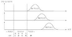
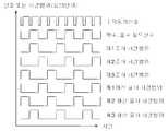
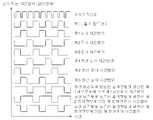
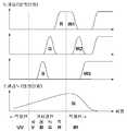
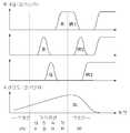
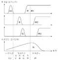
또한 본 발명의 또 다른 측면으로서 상기 어느 측면에 있어서 한층 더 전기 조사부는 전기 적외선의 각각을 위상차를 두어 강도 변조하여 전기 피사체에 조사하는 것을 구성을 개시한다.Further, as another aspect of the present invention, in any of the aspects described above, the electric irradiation unit further comprises a configuration for irradiating an electric subject with intensity modulation of each of the infrared rays with a phase difference.
또한 본 발명의 또 다른 측면으로서 전기 어느 측면에 있어서 한층 더 전기 조사부는 전기 적외선의 각각을 다른 주파수로 강도 변조하여 전기 피사체에 조사하는 구성을 개시한다.Further, as another aspect of the present invention, there is provided a configuration in which the electric irradiation unit further intensity-modulates each of the electric infrared rays at different frequencies and irradiates the electric subject in any aspect of the present invention.
또한 본 발명의 또 다른 측면으로서 상기 어느 측면에 있어서 한층 더 전기 조사부는 전기 적외선의 각각을 실질적으로 다른 시간범위에 전기 피사체에 조사하는 구성을 개시한다.Further, as another aspect of the present invention, in any of the above aspects, the electric irradiation unit further includes a configuration for irradiating each of the electric infrared rays to an electric subject in a substantially different time range.
본 발명의 또 다른 측면으로 상기 어느 측면에 있어서 한층 더 다른 파장강도분포를 가진 적외선을 LED 및 LD의 어느 하나 또는 복수를 점멸시키는 것에 의해 강도를 변조할 수 있다.According to another aspect of the present invention, in any of the above aspects, the intensity can be modulated by blinking one or more of the LED and the LD with an infrared ray having a further different wavelength intensity distribution.
본 발명의 또 다른 측면으로서 상기 어느 측면에 있어서 한층 더 다른 파장강도분포를 가진 적외선을 LED 및 LD의 어느 하나 또는 복수를 펄스적으로 발광시키는 것에 의해 강도를 변조할 수 있다.As another aspect of the present invention, the intensity can be modulated by irradiating one or more of the LED and the LD pulsively with an infrared ray having a different wavelength intensity distribution in any of the above aspects.
본 발명의 또 다른 측면으로서 상기 어느 측면에 있어서 한층 더 다른 파장강도분포를 가지는 적외선을 단형파, 사인파, 코사인파, 삼각파, 톱날파 등과 같은 파형, 그것들의 합성파, 듀티 비율 및 바이어스를 가진 그러한 파형, 합성파 등의 파형상에 강도를 변조할 수 있다.As yet another aspect of the present invention, there is provided a method of controlling an infrared ray having a different wavelength intensity distribution in any of the above aspects by using a waveform such as a short wave, a sine wave, a cosine wave, a triangle wave, a saw blade wave, It is possible to modulate the intensity of a wave such as a waveform or a synthetic wave.
본 발명의 또 다른 측면으로서 상기 어느 측면에 있어서 한층 더 다른 파장강도분포를 가지는 적외선을 개폐 슬릿 및 초퍼로 강도를 변조하여 피사체에 조사할 수 있다.As another aspect of the present invention, infrared rays having a different wavelength intensity distribution on any of the above aspects can be irradiated to an object by modulating the intensity with an opening / closing slit and a chopper.
본 발명의 또 다른 측면으로서 한층 더 다른 파장강도 분포를 가진 적외선의 각각의 펄스적외선 조사에 시간차를 두는 것에 의해 위상차를 만들어 강도 변조된 다른 파장강도 분포를 가진 적외선을 피사체에 조사하는 것이 바람직하다.As another aspect of the present invention, it is preferable to make a phase difference by applying a time difference to each pulse infrared irradiation of infrared ray having a different wavelength intensity distribution, and to irradiate the object with infrared rays having different intensity intensity distributions which are intensity-modulated.
본 발명의 또 다른 측면으로 한층 더 다른 파장강도 분포를 가진 적외선의 각각의 복수의 펄스적외선 조사에 시간차를 두는 것에 의해 위상차를 만들어 강도 변조시킨 다른 파장강도 분포를 가진 적외선을 피사체에 조사하는 것이 바람직하다.As another aspect of the present invention, it is preferable to irradiate the subject with infrared rays having different wavelength intensity distributions obtained by making a phase difference by applying a time difference to each of a plurality of pulsed infrared rays irradiation of each infrared ray having a different wavelength intensity distribution Do.
본 발명의 또 다른 측면으로 한층 더 다른 파장강도 분포를 가지며 또한 위상차를 두어 강도변조된 다른 파장강도 분포를 가진 적외선의 다른 위상의 차가 0.1초 이하인 것이 바람직하다.In another aspect of the present invention, it is preferable that the difference in the other phases of infrared rays having different wavelength intensity distributions and different intensity intensities of intensity-modulated infrared rays is 0.1 seconds or less.
본 발명의 또 다른 측면으로서 상기 어느 측면에 있어서 한층 더 다른 파장강도분포를 가진 적외선을 적외선 LED나 또는 적외선램프와 적외선필터에 의해 형성되는 것이 바람직하다.As another aspect of the present invention, it is preferable that the infrared ray having a different wavelength intensity distribution in any of the above aspects is formed by an infrared LED or an infrared lamp and an infrared ray filter.
또한 적외선필터로서는 각종 투과 파장대를 가진 적외선밴드 패스필터, 적외선파장 투과필터와 적외선단파장 투과필터의 조합 등이 있다.Examples of the infrared filter include an infrared band-pass filter having various transmission wavelength ranges, a combination of an infrared wavelength transmission filter and an infrared wavelength transmission filter.
본 발명의 또 다른 측면으로 상기 어느 것의 측면에 있어서 한층 더 다른 파장강도분포를 가진 적외선을 적외선 LED 및 또는 적외선 LD를 파장변조 또는 편광변조함에 의해 형성하는 것이 바람직하다.In another aspect of the present invention, it is preferable to form an infrared ray having a different wavelength intensity distribution by wavelength modulation or polarization modulation of an infrared LED and / or an infrared ray LD on either side of the above.
또한 파장변조 및 편광변조는 전자기적으로 실행하는 것이 바람직하다.It is also preferable to perform the wavelength modulation and the polarization modulation electronically.
본 발명의 또 다른 측면으로서 상기 어느 측면에 있어서 한층 더 적외선 LED 및 또는 적외선 LD가 750nm정도에서 1200nm정도의 파장범위의 내의 파장범위에서 발광하는 것이 바람직하다.As another aspect of the present invention, it is preferable that the infrared LED and / or the infrared LD further emits light in a wavelength range within a wavelength range of about 750 nm to 1200 nm in any of the above aspects.
본 발명의 또 다른 측면으로 상기 어느 것의 측면에 있어서 한층 더 적외선 LED 및 또는 적외선 LD가 750nm정도에서 1200nm정도의 파장범위 내의 중심파장으로 발광하는 것이 바람직하다.According to another aspect of the present invention, it is preferable that the infrared LED and / or the infrared LD further emits at a central wavelength within a wavelength range of from about 750 nm to about 1200 nm in any of the above aspects.
또한 본 발명의 또 다른 측면으로서 다른 파장강도분포를 가진 적외선을 복수의 적외선 광원에 의해 발하는 것이 바람직하다.As another aspect of the present invention, it is preferable to emit infrared rays having different wavelength intensity distributions by a plurality of infrared light sources.
또한 본 발명의 또 다른 측면으로서 다른 파장강도분포를 가진 적외선은 하나 이상의 적외선 광원을 복수로 분할하여 발하는 것이 바람직하다.In another aspect of the present invention, it is preferable that the infrared ray having the different wavelength intensity distribution divides at least one infrared light source into a plurality of infrared rays.
또한 본 발명의 또 다른 측면으로서 상기 어느 측면에 있어서 전기 조사부의 동작과 전기 촬상부의 동작이 동기하여 개시하는 것이 바람직하다.Further, as another aspect of the present invention, it is preferable that the operation of the electric irradiating unit and the operation of the electric image pickup unit start synchronously in any of the above aspects.
또한 본 발명의 또 다른 측면으로서 상기 어느 측면에 있어서 전기 조사부의 동작과 전기 촬상부의 동작과 전기 표색설정부의 동작이 동기하여 개시하는 것이 바람직하다.As another aspect of the present invention, it is preferable that the operation of the electric irradiation unit and the operation of the electric image pickup unit and the operation of the electric coloring setting unit start in synchronization with any of the above aspects.
또한 본 발명의 또 다른 측면으로서 상기 어느 측면에 있어서 전기 조사부의 동작 및 전기 촬상부의 동작이 소정의 시간간격으로 개시하는 것이 바람직하다.Further, as another aspect of the present invention, it is preferable that the operation of the electric irradiation unit and the operation of the electric imaging unit start at a predetermined time interval in any of the above aspects.
또한 본 발명의 또 다른 측면으로서 상기 어느 측면에 있어서 전기 조사부의 동작, 전기 촬상부의 동작 및 전기 표색설정부의 동작이 소정의 시간격차로 개시하는 것이 바람직하다.In still another aspect of the present invention, it is preferable that the operation of the electric irradiation unit, the operation of the electric image pickup unit, and the operation of the electric coloring setting unit are started with a predetermined time difference in any of the above aspects.
또한 본 발명의 또 다른 측면으로서 상기 어느 측면에 있어서 한층 더 전기 촬상부는 전기 피사체에 반사되는 다른 주파수로 강도변조된 다른 파장강도분포를 가진 적외선의 각각을 검파하고 분리하여 촬상하는 구성을 개시한다.According to still another aspect of the present invention, in any of the above aspects, a configuration is further disclosed in which an infrared ray having different wavelength intensity distribution intensity-modulated at different frequencies reflected by an electric subject is detected and separated for each of the infrared rays.
또한 본 발명의 다른 측면으로 상기 어느 측면에 있어서 전기 조사부의 동작 및 전기 촬상부의 동작이 10Hz이상의 주파수로 정기적으로 개시하는 것이 바람직하다.According to another aspect of the present invention, it is preferable that the operation of the electric irradiator and the operation of the electric image pickup unit periodically start at a frequency of 10 Hz or more.
또한 본 발명의 다른 측면으로서 상기 어느 측면에 있어서 전기 조사부의 동작, 전기 촬상부의 동작 및 전기 표색설정부의 동작이 10Hz 이상의 주파수로 정기적으로 개시하는 것이 바람직하다.In another aspect of the present invention, it is preferable that the operation of the electric irradiation unit, the operation of the electric image pickup unit, and the operation of the electric coloring setting unit periodically start at a frequency of 10 Hz or more.
이는 10Hz 이상의 주파수로 다른 화상을 연속표시하게 되면 사람의 눈에는 거의 컬러 정지화상 또는 컬러 동영상으로 보이기 때문이다.This is because, when a continuous display of another image at a frequency of 10 Hz or more is performed, it is almost displayed as a color still image or a color video in a human eye.
또한 본 발명의 다른 측면으로서 상기 어느 측면에 있어서 한층 더 전기 표시부는 전기 표색정보가 설정된 화상정보 및 전기 화상보존부에 보존된 전기 표색정보가 설정된 화상정보의 어느 하나 또는 양쪽인 표색정보가 설정된 화상정보가 나타내는 화상을 전기 표색정보에 따라 표시하는 구성을 개시한다.Further, as another aspect of the present invention, in any of the aspects described above, the electric display unit further includes an image display unit for displaying an image on which the color specification information, which is either or both of the image information for which the electric coloring information has been set and the image information for which the electric coloring information And displays the image represented by the information in accordance with the electric coloring information.
또한 본 발명의 또 다른 측면으로서 상기 어느 측면에 있어서 한층 더 전기 표시부는 전기 표색정보가 설정된 화상정보가 나타내는 화상 각각을 전기 표색정보에 따라 표색하여 동시에 표시하는 구성을 개시한다.Further, as another aspect of the present invention, in any of the above aspects, a further aspect of the present invention discloses a configuration in which each of the images represented by the image information in which the electric coloring information is set is colored according to the electric coloring information and displayed simultaneously.
또한 본 발명의 또 다른 측면으로서 상기 어느 측면에 있어서 전기 조사부의 동작, 전기 촬상부의 동작, 전기 표색설정부의 동작 및 전기 보존부의 동작이 동기하여 개시하는 것이 바람직하다.In still another aspect of the present invention, it is preferable that the operation of the electric irradiation unit, the operation of the electric image pickup unit, the operation of the electric coloring setting unit, and the operation of the electric storage unit are started synchronously in any of the above aspects.
또한 본 발명의 또 다른 측면으로서 상기 어느 측면에 있어서 전기 조사부의 동작, 전기 촬상부의 동작, 전기 표색설정부의 동작 및 전기 보존부의 동작이 소정의 시간간격으로 개시하는 것이 바람직하다.In still another aspect of the present invention, it is preferable that the operation of the electric irradiation unit, the operation of the electric image pickup unit, the operation of the electric coloring setting unit, and the operation of the electric storage unit are started at certain intervals in any of the above aspects.
또한 본 발명의 또 다른 측면으로서 상기 어느 측면에 있어서 전기 조사부, 전기 촬상부, 전기 제어처리부, 전기 표색설정부, 전기 화상보존부, 전기 화상변환부 및 전기 화상표시부의 어느 하나 또는 복수가 일체화되어 있는 것이 바람직하다.As another aspect of the present invention, any one or more of the electric irradiation unit, the electric imaging unit, the electric control processing unit, the electric coloring setting unit, the electric image storage unit, the electric image conversion unit, and the electric image display unit is integrated .
또한 본 발명의 또 다른 측면으로서 상기 어느 측면에 있어서 전기 제어처리부, 전기 조사부, 전기 촬상부, 전기 표색설정부, 전기 화상보존부, 전기 화상변환부 및 전기 화상표시부의 어느 하나 또는 복수가 온칩화되어 있는 것이 바람직하다.As another aspect of the present invention, any one or more of the electric control processing unit, the electric irradiation unit, the electric image pickup unit, the electric coloring setting unit, the electric image storage unit, the electric image conversion unit and the electric image display unit may be on- .
또한 본 발명의 또 다른 측면으로서 상기 어느 측면에 있어서 전기 조사부, 전기 촬상부, 전기 제어처리부, 전기 표색설정부, 전기 화상보존부, 전기 화상변환부 및 전기 화상표시부의 어느 하나 또는 복수는 한층 더 농도조정부를 갖추어 전기 농도조정부는 전기 표색정보가 설정된 화상정보, 전기 화상보존부에 보존된 전기 표색정보가 설정된 화상정보 및 전기 교환된 화상정보의 어느 하나 또는 복수의 표색의 명도 혹은 농도, 콘트라스트 및 감마 보정의 파라미터의 어느 하나 또는 복수를 조정하는 것이 바람직하다.In still another aspect of the present invention, any one or more of the electric irradiation unit, the electric imaging unit, the electric control processing unit, the electric coloring setting unit, the electric image storage unit, the electric image conversion unit, And the concentration adjusting unit adjusts the brightness or density of at least one of the color information, the image information for which the electric coloring information is set, the image information for setting the electric coloring information stored in the electric image storing unit, and the electric exchanged image information, It is preferable to adjust one or a plurality of gamma correction parameters.
또는 본 발명의 또 다른 측면으로서 상기 어느 측면에 있어서 전기 표색설정부 또는 전기 제어처리부는 RGB 비디오신호, NTSC 비디오신호, PAL 비디오신호, SECAM 비디오신호, 그 외의 컴퍼지트 영상신호, YC분리신호, S비디오신호, SDI신호, 그 외의 컴퍼지트 영상신호 MPEG계 디지털 영상신호, Ethernet영상신호 및 그 외의 디지털 영상신호 등의 어느 하나 또는 복수를 출력하는 신호출력부를 가지는 것이 바람직하다.In another aspect of the present invention, the electric-color specification setting unit or the electric control processing unit is configured to set the electric signal to the RGB signal, the NTSC video signal, the PAL video signal, the SECAM video signal, the other composite video signal, It is preferable to have a signal output unit for outputting any one or a plurality of video signals, SDI signals, other composite video signals, MPEG-based digital video signals, Ethernet video signals, and other digital video signals.
또한 본 발명의 다른 측면으로서 상기 어느 측면에 있어서 전기 조사부, 전기 촬상부, 전기 표색설정부 및 전기 제어처리부의 어느 하나 또는 복수는 RGB 비디오신호, NTSC 비디오신호, PAL 비디오신호, SECAM 비디오신호 그 외의 컴퍼지트 영상신호 YC 분리신호, S비디오신호, SDI신호 그 외의 컴퍼지트 영상신호 MPEG계 디지털 영상신호, Ethernet영상신호 및 그 외의 디지털 영상신호의 어느 하나 또는 복수를 출력하는 것이 바람직하다.As another aspect of the present invention, any one or more of the electric irradiation unit, the electric image pickup unit, the electric coloring setting unit, and the electric control processing unit may be an RGB video signal, an NTSC video signal, a PAL video signal, a SECAM video signal, A composite video signal YC separation signal, an S video signal, an SDI signal, and other composite video signals. It is preferable to output one or a plurality of MPEG system digital video signals, Ethernet video signals, and other digital video signals.
또한 본 발명의 또 다른 측면으로서 상기 어느 측면에 있어서 다른 파장강도 분포를 가진 적외선을 피사체에 조사하여 전기 피사체에 의해 반사된 다른 파장강도 분포를 가진 각각의 적외선에 의한 전기 피사체의 화상을 촬상하여 각각의 화상을 나타내는 화상정보를 형성하여 전기 형성된 화상정보를 나타내는 화상을 각각을 다른 단색에 의해 표색하는 것을 특징으로 하는 화상촬영방법을 개시한다.As another aspect of the present invention, an infrared ray having a different wavelength intensity distribution on any of the above aspects is irradiated to a subject to pick up an image of an electric subject by infrared rays having different wavelength intensity distributions reflected by the electric subject, And image forming means for forming an image representing the image information on which the electro formed image is formed by different monochromatic colors.
또한 본 발명의 또 다른 측면으로서 한층 더 전기 촬상된 화상 중 파장범위 또는 중심파장이 가장 단파장측에 있는 파장강도분포를 가지는 적외선에 의해 촬영된 제1화상을 「R」에 의해 표색하여 전기 제1 화상 이외의 전기 촬상된 화상을 전기 「R」 이외에 의해 표색하는 것을 개시한다.Further, as another aspect of the present invention, a first image photographed by infrared rays having a wavelength range or a wavelength intensity distribution in which the center wavelength is the shortest wavelength side among more electro-photographed images is expressed by " R "Quot; R ", other than the electric " R ".
또한 본 발명의 또 다른 측면으로서 한층 더 전기 촬상된 화상 중 파장범위 또는 중심파장이 가장 단파장측에 있는 파장강도 분포를 가지는 제1적외선에 의해 촬영된 제1화상을 「R」에 의해 표색하여 파장범위 또는 중심파장이 전기 제1적외선의 다음의 단파장측에 있는 파장강도분포를 가지는 제2적외선에 의해 촬영된 제2화상을 「G」에 의해 표색하여 전기 제1화상 및 전기 제2화상 이외의 전기 촬상된 화상을 전기 「B」 이외에 의해 표색하는 것을 개시한다.Further, as another aspect of the present invention, a first image photographed by a first infrared ray having a wavelength range or a wavelength range in which the center wavelength is the shortest wavelength side is further colored by "R" And a second image photographed by a second infrared ray having a wavelength intensity distribution whose central wavelength is in the short wavelength side of the first first infrared ray is represented by " G " The image picked up by the electrophotographic apparatus is colored by means other than the electric " B ".
또한 본 발명의 또 다른 측면으로서 상기 어느 측면에 있어서 한층 더 전기 제2화상을 「B」에 의해 표색하여 전기 제1화상 및 전기 제2화상을 「G」에 의해 표색하는 것이 바람직하다.In still another aspect of the present invention, it is preferable that the electrical second image is further colored by "B", and the electrical first image and the electrical second image are colored by "G" in any of the above aspects.
또한 본 발명의 또 다른 측면으로 상기 어느 측면에 있어서 한층 더 전기 다른 단색을 「R」, 「G」 및 「B」의 어느 하나 또는 복수 혹은 적당하게 다른 단색 또는 원색 한층 더 그것들의 조합을 하는 것이 바람직하다.Further, according to another aspect of the present invention, it is preferable that any one or more of the "R", "G" and "B" or any other suitable monochromatic or primary color and further combinations thereof desirable.
또한 본 발명의 또 다른 측면으로서 상기 어느 측면에 있어서 한층 더 전기 제1화상을 「R」에 의해 표색하여 전기 제1화상 이외의 전기 촬상된 화상을 「G」 및 「B」의 어느 하나 또는 복수 혹은 적당하게 다른 단색 또는 원색 한층 더 그것들의 조합에 의해 표색되는 것이 바람직하다.Further, as another aspect of the present invention, in any of the aspects described above, it is preferable that the electric first image is further colored by " R " so that the electrically photographed image other than the first electric image is referred to as either " G " Or alternatively by a combination of different monochromatic colors or primary colors.
또한 본 발명의 또 다른 측면으로서 상기 어느 측면에 있어서 한층 더 전기 다른 단색 또는 원색을 「C」, 「M」 및 「Y」의 어느 하나 또는 복수 혹은 적당하게 다른 단색 또는 원색 한층 더 그것들의 조합하는 것이 바람직하다.Further, as another aspect of the present invention, in any of the aspects described above, it is also possible to use one or more of monochromatic or primary colors of "C", "M", and "Y" .
또한 본 발명의 또 다른 측면으로서 상기 어느 측면에 있어서 한층 더 전기 표색된 화상을 가법혼색한 적당한 2단색, 2원색 또는 「R」, 「G」 및 「B」의 어느 둘에 의한 컬러화상을 형성하는 것이 바람직하다.Further, as another aspect of the present invention, in any of the aspects described above, a color image of a suitable two-monochromatic color, two primary colors, or "R", "G", and "B" .
또한 본 발명의 또 다른 측면으로서 상기 어느 측면에 있어서 한층 더 전기 표색된 화상을 가법혼색한 적당한 2단색, 2원색 또는 「C」, 「M」 및 「Y」의 어느 둘에 의한 컬러화상을 형성하는 것이 바람직하다.Further, as another aspect of the present invention, in any of the above aspects, a color image of a suitable two-monochromatic color, two primary colors, or "C", "M", and "Y" .
또한 본 발명의 또 다른 측면으로서 상기 어느 측면에 있어서 한층 더 전기 표색된 화상을 가법혼색하여 적당한 3단색, 3원색 또는 「R」, 「G」 및 「B」에 의해 컬러화상을 형성하는 것이 바람직하다.Further, as another aspect of the present invention, it is preferable that an electro-colored image is additionally mixed in any of the above aspects so that a color image is formed by appropriate three monochromatic colors, three primary colors, or "R", "G" Do.
또한 본 발명의 또 다른 측면으로서 상기 어느 측면에 있어서 한층 더 전기 표색된 화상을 가법혼색한 적당한 3단색, 3원색 또는 「C」, 「M」 및 「Y」에 의한 컬러화상을 형성하는 것이 바람직하다.Further, as another aspect of the present invention, it is preferable to form a suitable three-monochromatic color, three primary colors or a color image by "C", "M" and "Y" in which the electro- Do.
또한 본 발명의 또 다른 측면으로서 상기 어느 측면에 있어서 한층 더 전기 RGB컬러 화상을 RGBB컬러, 인덱스컬러, CMY컬러, CMYK컬러 또는 그 외의 별종의 컬러 표시에 의한 변환 컬러화상으로 변화하는 것이 바람직하다.In still another aspect of the present invention, it is preferable that the electric RGB color image is further changed into an RGBB color, an index color, a CMY color, a CMYK color, or a converted color image by a different kind of color display.
또한 본 발명의 또 다른 측면으로서 상기 어느 측면에 있어서 한층 더 전기 화상에 가산, 감산, 승산 및 제산의 어느 것의 사칙연산, 지수관수, 대수관수 및 임의관수의 어느 하나 또는 복수를 이용한 연산을 적용하여 변환시킨 화상을 형성하는 것이 바람직하다.Further, as another aspect of the present invention, in any of the aspects described above, the arithmetic operation of addition, subtraction, multiplication, and division is applied to the electric image, and an arithmetic operation using any one or more of the exponent number, the logarithm number, It is preferable to form the converted image.
또한 본 발명의 또 다른 측면으로서 상기 어느 측면에 있어서 한층 더 전기 촬영된 영상, 전기 촬상된 화상, 2단색 또는 2원색 컬러화상, 3단색 또는 3원색 컬러화상, RGB컬러화상, CMY컬러화상, 변환된 화상 및 변환컬러화상의 어느 하나 또는 복수를 보존하는 것이 바람직하다.Further, as another aspect of the present invention, there is provided a color image conversion method comprising the steps of: (a) obtaining a first color image, a first color image, a second color image, It is preferable to store one or a plurality of converted images and converted color images.
또한 본 발명의 또 다른 측면으로서 상기 어느 측면에 있어서 한층 더 전기 촬영된 영상, 전기 촬상된 화상, 2단색 또는 2원색 컬러화상, 3단색 또는 3원색 컬러화상, RGB컬러화상, CMY컬러화상, 변환된 화상 및 변환컬러화상의 어느 하나 또는 복수의 표시가 바람직하다.Further, as another aspect of the present invention, there is provided a color image conversion method comprising the steps of: (a) obtaining a first color image, a first color image, a second color image, And one or a plurality of displays of converted color images are preferable.
또한 본 발명의 또 다른 측면으로서 상기 어느 측면에 있어서 한층 더 전기 표색된 화상, 2단색 또는 2원색 컬러화상, 3단색 또는 3원색컬러화상, RGB컬러화상, 변환된 화상 및 변환컬러화상의 어느 하나 또는 복수의 컬러의 컬러밸런스, 색상, 명도 또는 농도, 콘트라스트 및 감마보정의 파라미터의 어느 하나 또는 복수를 각각 조정하는 것이 바람직하다.Further, as another aspect of the present invention, in any of the aspects described above, any one of an electro-colored image, a two-monochromatic or two-primary color image, a three-monochromatic or three primary color image, an RGB color image, Or a color balance, a color, a brightness or a density of a plurality of colors, a parameter of a contrast and a gamma correction, respectively.
또한 본 발명의 또 다른 측면으로서 상기 어느 측면에 있어서 한층 더 둘, 셋 또는 넷 이상의 다른 파장강도분포를 가진 적외선을 피사체에 조사하는 것이 바람직하다.Further, as another aspect of the present invention, it is preferable to irradiate the subject with infrared rays having two, three, or four or more different wavelength intensity distributions in any of the above aspects.
또한 본 발명의 또 다른 측면으로서 상기 어느 측면에 있어서 한층 더 전기 다른 파장강도분포를 가진 적외선의 각각을 위상차를 더해 강도 변조하여 전기 피사체에 조사하는 것을 개시한다.Further, as another aspect of the present invention, it is disclosed that, in any of the above aspects, each infrared ray having a different wavelength intensity distribution is subjected to intensity modulation by adding a phase difference to irradiate an electric subject.
또한 본 발명의 또 다른 측면으로서 상기 어느 측면에 있어서 한층 더 전기 다른 파장강도분포를 가진 적외선의 각각을 다른 주파수로 강도 변조하여 전기 피사체에 조사하는 것을 개시한다.As another aspect of the present invention, there is disclosed a method of intensity-modulating each of infrared rays having different wavelength intensity distributions with different frequencies to irradiate an electric subject in any of the above aspects.
또한 본 발명의 또 다른 측면으로서 상기 어느 측면에 있어서 한층 더 전기 다른 파장강도분포를 가진 적외선을 다른 시간범위에 전기 피사체에 조사하는 것을 개시한다. 즉 각각의 적외선은 실질적으로 동시에 조사되는 것이 바람직하다.Further, as another aspect of the present invention, there is disclosed a method of irradiating infrared rays having different wavelength intensity distributions to an electric subject in different time ranges in any of the above aspects. That is, each infrared ray is preferably irradiated substantially simultaneously.
또한 본 발명의 또 다른 측면으로서 상기 어느 측면에 있어서 한층 더 전기 조사의 동작과 전기 촬상의 동작을 동기하여 개시하는 것이 바람직하다.In still another aspect of the present invention, in any of the above aspects, it is preferable that the operation of the electric irradiation and the operation of the electric imaging are started in synchronization with each other.
또한 본 발명의 또 다른 측면으로서 상기 어느 측면에 있어서 한층 더 전기 조사의 동작과 전기 촬상의 동작과 전기 표색의 실행을 동기하여 개시하는 것이 바람직하다.As still another aspect of the present invention, it is preferable that the operation of the electric irradiation and the operation of the electric imaging and the execution of the electric coloring are further synchronized with each other in any of the above aspects.
또한 본 발명의 또 다른 측면으로서 피사체로부터 적외선을 다른 파장강도 분포를 가진 적외선으로 분리하여 전기 다른 파장강도분포를 가진 각각의 적외선에 의해 전기 피사체의 화상을 촬상하여 전기 촬상된 화상 중 파장범위 또는 중심파장이 가장 단파장측에 있는 파장강도분포를 가진 적외선에 의해 촬영된 제1화상을 「R」에 의해 표색하여 전기 제1화상 이외의 전기 촬상된 화상을 전기 「R」 이외에 의해 표색하는 것을 특징으로 하는 화상촬상방법을 개시한다.As another aspect of the present invention, there is provided a method of separating an infrared ray from a subject into infrared rays having different wavelength intensity distributions, picking up an image of an electric subject by each infrared ray having a different wavelength intensity distribution, The first image photographed by infrared rays having a wavelength intensity distribution whose wavelength is the shortest wavelength side is colored by " R " to characterize an electrically photographed image other than the first electrical image by means other than electricity "R" An image pick-up method is disclosed.
또한 본 발명의 또 다른 측면으로서 전기 촬상된 화상 중 파장범위 또는 중심파장이 가장 단파장측에 있는 파장강도분포를 가진 제1적외선에 의해 촬영된 제1화상을 「R」에 의해 표색하여 파장범위 또는 중심파장이 전기 제1적외선의 다음의 단파장측에 있는 파장강도분포를 가진 제2적외선에 의해 촬영된 제2화상을 「G」에 의해 표색하여 전기 제1화상 및 전기 제2화상 이외의 화상을 「B」에 의해 표색하는 전기 촬영방법을 개시한다.Further, as another aspect of the present invention, a first image photographed by a first infrared ray having a wavelength range or a central wavelength in the wavelength range of the electro-photographed image is represented by " R " A second image photographed by a second infrared ray having a wavelength intensity distribution whose center wavelength is on the next short wavelength side of the first infrared ray is represented by " G "Quot;, and " B ".
또한 본 발명의 또 다른 측면으로서 상기 어느 측면에 있어서 한층 더 전기 제2화상을 「B」에 의해 표색하여 전기 제1화상 및 전기 제2화상 이외의 화상을 「G」에 의해 표색하는 것이 바람직하다.Further, as another aspect of the present invention, in any of the above aspects, it is preferable to further color the second electrical image by " B " and to color an image other than the first electrical image and the second electrical image by " G & .
또한 본 발명의 또 다른 측면으로서 상기 어느 측면에 있어서 한층 더 하나의 파장강도분포를 가진 적외선, 둘 또는 셋 이상의 다른 파장강도분포를 가진 적외선을 피사체에 조사하는 것이 바람직하다.Further, as another aspect of the present invention, it is preferable to irradiate the subject with infrared rays having two or more different wavelength intensity distributions with one wavelength intensity distribution in any of the above aspects.
또한 본 발명의 또 다른 측면으로서 상기 어느 측면에 있어서 한층 더 전기 조사의 동작과 전기 촬상의 동작을 동기하여 개시하는 것이 바람직하다.In still another aspect of the present invention, in any of the above aspects, it is preferable that the operation of the electric irradiation and the operation of the electric imaging are started in synchronization with each other.
또한 본 발명의 또 다른 측면으로서 상기 어느 측면에 있어서 한층 더 전기 조사의 동작과 전기 촬상과 전기 표색의 실행을 동기하여 개시하는 것이 바람직하다.In still another aspect of the present invention, it is preferable that, in any of the above aspects, the operation of the electric irradiation and the execution of the electric imaging and the electric coloring are started in synchronization with each other.
또한 본 발명의 또 다른 측면으로서 피사체로부터의 광선을 다른 파장강도분포를 가진 광선으로 분리하여 전기 다른 파장강도 분포를 가진 각각의 광선에 의해 전기 피사체의 화상을 촬상하여 전기 촬상된 화상 중 「R파장영역」을 가진 가시광선 및 전기 「R파장영역」에 가장 가까운 파장강도분포를 가진 적외선에 의해 촬상된 제1화상을 「R」에 의해 표색하여 전기 제1화상 이외의 전기 촬상된 화상을 전기 「R」 이외에 의해 표색하는 것을 특징으로 하는 화상촬영방법을 개시한다.Further, as another aspect of the present invention, a light beam from a subject is separated into light beams having different wavelength intensity distributions, and an image of an electric subject is picked up by each light beam having a different wavelength intensity distribution, Quot; R " region and the electric " R wavelength region " are labeled with " R "Quot; R ". < / RTI >
또한 본 발명의 또 다른 측면으로서 전기 촬상된 화상 중 「R파장영역」을 가진 가시광선 및 전기 「R파장영역」에 가장 가까운 파장강도분포를 가진 제1적외선에 의해 촬상된 제1화상을 「R」에 의해 표색하여 「G파장영역」을 가진 가시광선 및 전기 제1적외선에 가까운 파장강도 분포를 가진 제2적외선에 의해 촬상된 제2화상을 「G」에 의해 표색하여 전기 제1화상 및 전기 제2화상 이외의 화상을 「B」에 의해 표색하는 것을 특징으로 하는 화상촬영방법을 개시한다.As another aspect of the present invention, a first image picked up by a first infrared ray having a wavelength intensity distribution closest to the visible light ray and the electric " R wavelength region " having the " R wavelength region " And a second image picked up by a second infrared ray having a wavelength intensity distribution close to the first infrared ray is represented by " G " to form an electric first image and electric And an image other than the second image is colored by " B ".
또한 본 발명의 또 다른 측면으로서 상기 어느 측면에 있어서 한층 더 전기 제2화상을 「B」에 의해 표색하여 전기 제1화상 및 전기 제2화상을 「G」에 의해 표색하는 것이 바람직하다.In still another aspect of the present invention, it is preferable that the electrical second image is further colored by "B", and the electrical first image and the electrical second image are colored by "G" in any of the above aspects.
또한 본 발명의 또 다른 측면으로서 상기 어느 측면에 있어서 한층 더 하나, 둘 또는 셋 이상의 다른 파장강도분포를 가진 광선을 피사체에 조사하는 것이 바람직하다.As another aspect of the present invention, it is preferable to irradiate a subject with a light beam having one, two, or three or more different wavelength intensity distributions in any of the above aspects.
또한 본 발명의 또 다른 측면으로서 상기 어느 측면에 있어서 한층 더 전기 다른 파장강도분포를 가진 광선을 위상차를 두어 강도 변조하여 전기 피사체에 조사하는 것을 개시한다.As another aspect of the present invention, there is disclosed a method of irradiating an electric subject by intensity-modulating a light ray having a different wavelength intensity distribution with a phase difference in any of the above aspects.
또한 본 발명의 또 다른 측면으로서 상기 어느 측면에 있어서 한층 더 전기 다른 파장강도를 가진 광선의 각각을 다른 주파수로 강도변조하여 전기 피사체에 조사하는 것을 개시한다.As another aspect of the present invention, there is disclosed a method for intensity-modulating each of light beams having different wavelength intensities at different frequencies and irradiating an electric subject in any of the above aspects.
또한 본 발명의 또 다른 측면으로서 상기 어느 측면에 있어서 한층 더 전기 다른 파장강도분포를 가진 광선을 다른 시간범위에 전기 피사체에 조사하는 것을 개시한다. 즉 각각의 적외선은 실질적으로 동시에 조사되는 것이 바람직하다.Still another aspect of the present invention is to irradiate an electric subject in a different time zone with a light beam having a different wavelength intensity distribution in any of the above aspects. That is, each infrared ray is preferably irradiated substantially simultaneously.
또한 본 발명의 또 다른 측면으로서 상기 어느 측면에 있어서 한층 더 전기 조사의 동작과 전기 촬상의 동작을 동기하여 개시하는 것이 바람직하다.In still another aspect of the present invention, in any of the above aspects, it is preferable that the operation of the electric irradiation and the operation of the electric imaging are started in synchronization with each other.
또한 본 발명의 또 다른 측면으로서 전기 어느 측면에 있어서 한층 더 전기 조사의 동작과 전기 촬상의 동작과 전기 표색의 실행을 동기하여 개시하는 것이 바람직하다.As yet another aspect of the present invention, it is preferable to start the operation of the electric irradiation, the operation of the electric image pickup, and the execution of the electric coloring synchronously in any aspect of the present invention.
또한 본 발명의 또 다른 측면으로서 상기 어느 측면에 있어서 전기 촬상된 화상을 표색하여 표시하는 것이 바람직하다.Further, as another aspect of the present invention, it is preferable to display and display an image that is electrically photographed in any of the above aspects.
또한 본 발명의 또 다른 측면으로서 상기 어느 측면에 있어서 전기 촬상된 화상을 보존하는 것이 바람직하다.Further, as another aspect of the present invention, it is preferable to preserve the electro-photographed image on any of the above aspects.
또한 본 발명의 또 다른 측면으로서 상기 어느 측면에 있어서 전기 촬상된 화상 및 전기 보존된 화상의 어느 하나 또는 양쪽을 표색하여 표시하는 것이 바람직하다.Further, as another aspect of the present invention, it is preferable that either or both of the electrically photographed image and the electrically preserved image are displayed and displayed in any of the above aspects.
또한 본 발명의 또 다른 측면으로서 상기 어느 측면에 있어서 전기 촬상된 화상 및 전기 보존된 화상의 어느 하나 또는 양쪽을 표색하여 동기하여 표시하는 것이 바람직하다.As another aspect of the present invention, it is preferable that either or both of the electro-photographed image and the electrically preserved image are displayed in synchronism with each other.
또한 본 발명의 또 다른 측면으로서 상기 어느 측면에 있어서 전기 촬상된 화상 및 전기 보존된 화상의 어느 하나 또는 양쪽을 표색하여 다른 시간범위에 표시하는 것이 바람직하다.As another aspect of the present invention, it is preferable that either or both of the electro-photographed image and the electrically preserved image are displayed on any of the above-described aspects and displayed in a different time range.
더욱이 본 발명의 또 다른 측면으로서 상기 어느 측면에 있어서 한층 더 피사체로부터의 광선이 피사체에 의해 반사된 광선, 피사체를 투과한 광선 또는 피사체로부터 반사된 광선의 어느 하나 또는 복수인 것이 바람직하다.As yet another aspect of the present invention, it is preferable that the light rays from the subject are further reflected by the subject, the light rays transmitted through the subject, or the light rays reflected from the subject.
더욱이 일반적으로 광선 또는 빛은 자외선, 가시광선 및 적외선의 어느 하나 또는 복수로 이루어진다.Furthermore, generally, the light ray or light is composed of any one or a plurality of ultraviolet rays, visible rays and infrared rays.
본 발명의 또 다른 측면으로서 상기 어느 측면에 있어서 한층 더 자외선, 가시광선 및 적외선의 어느 하나 또는 복수를 이용하는 것이 바람직하다.As another aspect of the present invention, it is preferable to use any one or more of ultraviolet rays, visible rays, and infrared rays in any of the above aspects.
본 발명의 또 다른 측면으로서 상기 어느 측면에 있어서 한층 더 태양광선을 이용하는 것이 바람직하다.As yet another aspect of the present invention, it is preferable to further use sunlight in any of the above aspects.
본 발명의 또 다른 측면으로서 상기 어느 측면에 있어서 한층 더 달로부터의 광선을 이용하는 것이 바람직하다.As yet another aspect of the present invention, it is preferable to use more rays from the moon in any of the above aspects.
본 발명의 또 다른 측면으로서 상기 어느 측면에 있어서 한층 더 별이나 성운 등 우주로부터의 광선을 이용하는 것이 바람직하다.As another aspect of the present invention, it is preferable to use light rays from the universe such as stars or nebulae in any of the above aspects.
본 발명의 또 다른 측면으로서 상기 어느 측면에 있어서 한층 더 백열등 광선을 이용하는 것이 바람직하다.As yet another aspect of the present invention, it is preferable to use an incandescent lamp in any of the above aspects.
본 발명의 또 다른 측면으로서 상기 어느 측면에 있어서 한층 더 형광등 광선을 이용하는 것이 바람직하다.As yet another aspect of the present invention, it is preferable to use more fluorescent light in any of the above aspects.
본 발명의 또 다른 측면으로서 상기 어느 측면에 있어서 한층 더 자외선 내지는 가시광선 내지는 적외선을 바이어스 광으로 이용하는 것이 바람직하다.As another aspect of the present invention, it is preferable to use ultraviolet rays or visible rays or infrared rays as bias light in any of the above aspects.
본 발명의 또 다른 측면으로서 상기 어느 측면에 있어서 한층 더 주간에 전기 촬상부에 있는 컬러CCD카메라를 이용, 야간에 전기 촬상부에 있는 흑백CCD카메라를 이용하게끔 전환하는 것이 바람직하다.As another aspect of the present invention, it is preferable to use a color CCD camera in the electric image pickup unit during a day and a monochrome CCD camera in the electric image pickup unit in the nighttime in any of the above aspects.
더욱이 전환은 광검출소자, 조도계, 태양전지 등에 의해 밝기를 계측하는 것을 근거하여 실행하는 것이 바람직하다.Furthermore, it is preferable that the conversion is carried out based on the measurement of the brightness by the light detector, the illuminometer, the solar battery and the like.
본 발명의 또 다른 측면으로서 상기 어느 측면에 있어서 한층 더 주간과 야간을 함께 전기 촬상부인 흑백 CD카메라를 이용하는 것이 바람직하다.As another aspect of the present invention, in any of the above aspects, it is preferable to use a monochrome CD camera, which is an electric image pickup unit, together with daytime and nighttime.
본 발명의 또 다른 측면으로서 상기 어느 측면에 있어서 한층 더 주간과 야간을 함께 전기 촬상부인 컬러 CD카메라를 이용하는 것이 바람직하다.As another aspect of the present invention, in any of the above aspects, it is preferable to use a color CD camera, which is an electric image pickup unit, with a daytime and a nighttime together.
본 발명의 또 다른 측면으로서 상기 어느 측면에 있어서 야간에는 적외선 조명을 이용하여 전기 촬상부인 컬러CCD카메라를 이용하는 것이 바람직하다.As another aspect of the present invention, in any of the above aspects, it is preferable to use a color CCD camera which is an electric imaging unit using infrared illumination at night.
본 발명의 또 다른 측면으로서 상기 어느 측면에 있어서 한층 더 주간에 전기 촬상부인 컬러CMOS카메라를 이용하고 야간에 전기 촬상부인 흑백CMOS카메라를 이용하게끔 전환하는 것이 바람직하다. 더욱이 전환은 광검출소자, 조도계 및 태양전지 등에 의해 밝기를 계측하는 것을 근거하여 실행하는 것이 바람직하다.As another aspect of the present invention, it is preferable to use a color CMOS camera, which is an electrical image pickup unit, for a day and a monochrome CMOS camera, which is an electrical image pickup unit, at night. Furthermore, it is preferable that the conversion is carried out on the basis of measuring the brightness by means of an optical detector, an illuminometer, a solar cell or the like.
본 발명의 또 다른 측면으로서 상기 어느 측면에 있어서 한층 더 주간과 야간 함께 전기 촬상부인 흑백CMOS카메라를 이용하는 것이 바람직하다.As another aspect of the present invention, in any of the above aspects, it is preferable to use a monochrome CMOS camera, which is an electric imaging unit, in conjunction with daytime and nighttime.
본 발명의 또 다른 측면으로서 상기 어느 측면에 있어서 한층 더 주간과 야간 함께 전기 촬상부인 컬러CMOS카메라를 이용하는 것이 바람직하다.As another aspect of the present invention, in any of the above aspects, it is preferable to use a color CMOS camera, which is an electric imaging unit, in conjunction with daytime and nighttime.
본 발명의 또 다른 측면으로서 상기 어느 측면에 있어서 한층 더 주간에 적외선 컷트 필터를 이용하여 야간에 적외선 컷트 필터를 이용하지 않게 전환하는 것이 바람직하다. 더욱이 전환은 광검출소자, 조도계 및 태양전지 등에 의해 밝기를 계측하는 것을 근거하여 실행하는 것이 바람직하다.As another aspect of the present invention, in any of the above aspects, it is preferable that the infrared cut filter is used in the daytime so that the infrared cut filter is not used at night. Furthermore, it is preferable that the conversion is carried out on the basis of measuring the brightness by means of an optical detector, an illuminometer, a solar cell or the like.
본 발명의 또 다른 측면으로서 상기의 어느 측면에 있어서 한층 더 컬러 전기 촬상부인 CCD 내지는 전기 컬러CMOS카메라의 경우는 NTSC비디오신호와 같이 RGB성분을 하나로 합쳐 1화상으로 하는 것이 바람직하다.As another aspect of the present invention, in any of the above aspects, in the case of a CCD or an electric color CMOS camera, which is a further color electronic image pickup unit, it is preferable to combine RGB components into one image such as an NTSC video signal.
본 발명의 또 다른 측면으로서 상기 어느 측면에 있어서 한층 더 감시카메라 등의 감시 내지는 보안용에 이용하는 것이 바람직하다.As yet another aspect of the present invention, it is preferable that the above-described aspects are further used for monitoring or security of a surveillance camera or the like.
본 발명의 또 다른 측면으로서 상기 어느 측면에 있어서 한층 더 암시고글 내지는 암시안경으로서 이용하는 것이 바람직하다.As another aspect of the present invention, it is preferable that the glass be used as the dark goggles or the dark glasses in any of the above aspects.
본 발명의 또 다른 측면으로서 상기 어느 측면에 있어서 한층 더 컬러화상 표시를 흑백화상 표시로 실행하여도 좋다.As another aspect of the present invention, in any of the above aspects, the color image display may be performed by a monochrome image display.
본 발명의 또 다른 측면으로서 상기 어느 측면에 있어서 한층 더 복수의 조사부를 복수개소에 고정설정하여 운반가능하게 일체화시킨 촬상부와 표색설정부에 의해 화상촬영을 행하여도 좋다.As another aspect of the present invention, the image taking may be performed by the imaging unit and the color setting unit, which are integrated with each other so that a plurality of irradiation units can be fixedly set at a plurality of locations and transported.
이 경우 조사부는 독립된 것 처럼 보이나 본 발명에 의한 화상촬영을 위하여는 별도 촬상부, 표색설정부, 제어처리부가 필요하다.In this case, the irradiation unit seems to be independent, but a separate imaging unit, color setting unit, and control processing unit are required for image capturing according to the present invention.
본 발명의 또 다른 측면으로서 상기 어느 측면에 있어서 한층 더 조사부, 촬상부, 표색설정부, 제어처리부 등을 천정 등의 실내 및 자동차, 전자, 선박 및 비행기 등의 차내, 선내, 기내 등에 설치하여도 좋다.As another aspect of the present invention, even when the irradiation unit, the image pickup unit, the color setting unit, the control processing unit, and the like are installed in a room such as a ceiling or in a car, on board, good.
본 발명의 또 다른 측면으로서 상기 어느 측면에 있어서 한층 더 조사부, 촬상부, 표색설정부, 제어처리부 등을 가로등이나 간판 및 신호기 등에 이용하는 기둥에 설치하여도 좋다.As yet another aspect of the present invention, in any of the above aspects, the irradiation unit, the imaging unit, the color setting unit, the control processing unit, and the like may be provided on a column used for a streetlight, a signboard,
본 발명의 또 다른 측면으로서 상기 어느 측면에 있어서 한층 더 조사부, 촬상부, 표색설정부, 제어처리부 등을 가옥이나 빌딩 등의 건조물에 설치하여도 좋다.As yet another aspect of the present invention, in any of the above aspects, the irradiation unit, the imaging unit, the coloring setting unit, the control processing unit, and the like may be provided in a building such as a house or a building.
본 발명의 또 다른 측면으로서 상기 어느 측면에 있어서 한층 더 조사부, 촬상부, 표색설정부, 제어처리부 등을 형광등에 내장하여도 좋다.As yet another aspect of the present invention, in any of the above aspects, the illuminating unit, the imaging unit, the coloring setting unit, the control processing unit, and the like may be incorporated in the fluorescent lamp.
본 발명의 또 다른 측면으로서 소정의 파장강도분포를 가지는 적외선을 반사하는 피착성부재를 갖추는 피사체에 적외선을 조사하여 전기 피사체에 의해 반사된 적외선을 촬상하는 것에 의해 전기 피사체의 컬러화상을 얻는 것이 바람직하다.As another aspect of the present invention, it is preferable to obtain a color image of an electric subject by irradiating infrared rays on a subject equipped with a fusible member for reflecting infrared rays having a predetermined wavelength intensity distribution to pick up infrared rays reflected by the electric subject Do.
본 발명의 또 다른 측면으로서 상기 어느 측면에 있어서 소정의 파장강도분포를 가진 적외선을 반사하는 피착성부재를 갖추는 피사체에 적외선을 조사하여 전기 피사체에 의해 반사된 적외선을 촬상하는 것에 의해 가시영역의 백색광 하에 있어서의 피사체의 컬러와 동일 또는 근사한 전기 피사체의 컬러화상을 얻는 것이 바람직하다.As another aspect of the present invention, an infrared ray is irradiated to a subject equipped with a fusible member for reflecting infrared rays having a predetermined wavelength intensity distribution on any of the above aspects to pick up infrared rays reflected by the electric subject, It is preferable to obtain a color image of an electric subject which is the same as or approximate to the color of the subject under the above-mentioned condition.
본 발명의 또 다른 측면으로서 조사부, 분리부, 촬상부 및 표색설정부를 갖추고 전기 조사부는 적외선을 피사체에 조사하고 전기 분리부는 전기 피사체에 의해 반사된 적외선을 다른 파장강도분포를 가진 적외선으로 분리, 전기 촬상부는 각각의 전기 적외선에 의해 전기 피사체의 화상을 촬상하여 화상정보를 형성하고 전기 표색설정부는 전기 형성된 화상정보가 나타내는 화상 각각을 다른 단색에 의해 표색하기 위한 표색정보를 전기 화상정보에 설정하는 것을 특징으로 하는 화상촬영장치를 제공한다.In another aspect of the present invention, there is provided an image processing apparatus including an irradiating unit, a separating unit, an image pickup unit, and a color setting unit, wherein the electric irradiating unit irradiates infrared rays to a subject and the electric separating unit separates infrared rays reflected by the electric subject into infrared rays having different wavelength intensity distributions, The image pickup section forms image information by picking up an image of the electric subject by each of the infrared rays of the respective electric power and the electric coloring setting section sets the coloring information for coloring each of the images represented by the formed image information by different monochromatic colors to the electric image information The present invention also provides an image photographing apparatus.
본 발명의 또 다른 측면으로서 분리부, 촬상부 및 표색설정부를 갖추고 전기 분리부는 피사체로부터의 광선을 다른 파장강도분포를 가진 광선을 분리하여 주고 전기 촬상부는 각각의 전기 다른 파장강도분포를 가진 광선에 의해 전기 피사체의 화상을 촬상하여 화상정보를 형성하며 전기 표색설정부는 전기 형성된 화상정보가 나타내는 화상의 각각을 다른 단색에 의해 표색하기 위한 표색정보를 전기 화상정보에 설정하는 것을 특징으로 하는 화상촬영장치를 제공한다.In another aspect of the present invention, there is provided a light emitting device having a separating portion, an image pickup portion, and a color setting portion, wherein the electric separating portion separates a light beam from a subject into light beams having different wavelength intensity distributions, And the electric-color-signal setting unit sets the color-matching information for coloring each of the images represented by the electrically formed image information by different monochromatic colors to the electric image information, Lt; / RTI >
본 발명의 또 다른 측면으로서 피사체로부터의 적외선을 다른 파장강도를 가진 적외선으로 분리하여 다른 파장강도를 가진 각각의 적외선에 의한 전기 피사체의 화상을 나타내는 화상정보를 형성하여 전기 형성된 화상정보의 나타내는 화상의 각각을 다른 단색에 의해 표색하는 것을 특징으로 하는 화상촬영방법을 제공한다.As another aspect of the present invention, there is provided a method of manufacturing an image display apparatus, comprising: separating infrared rays from a subject by infrared rays having different wavelength intensities to form image information representing an image of an electric subject by infrared rays having different wavelength intensities, And each of the images is colored by another monochromatic color.
본 발명의 또 다른 측면으로서 적외선을 피사체에 조사하여 전기 피사체에 의해 반사된 적외선을 다른 파장강도 분포를 가진 적외선으로 분리하여 전기 다른 파장강도 분포를 가진 각각의 적외선에 의해 전기 피사체의 화상을 촬상하여 각각의 화상을 나타내는 화상정보를 형성하여 전기 형성된 화상정보의 나타내는 화상의 각각을 다른 단색에 의해 표색하는 것을 특징으로 하는 화상촬영방법을 제공한다.As another aspect of the present invention, an infrared ray is irradiated to a subject, infrared rays reflected by the electric subject are separated into infrared rays having different wavelength intensity distributions, and an image of the electric subject is picked up by respective infrared rays having different wavelength intensity distributions There is provided an image photographing method characterized by forming image information representing each image and coloring each of the images represented by the formed image information by different monochromatic colors.
본 발명의 또 다른 측면으로서 피사체로부터의 광선을 다른 파장강도 분포를 가진 광선으로 분리하여 전기 다른 파장강도를 가진 각각의 적외선에 의해 전기 피사체의 화상을 촬상하여 각각의 화상을 나타내는 화상정보를 형성하여 전기 형성된 화상정보의 나타내는 화상의 각각을 다른 단색에 의해 표색하는 것을 특징으로 하는 화상촬영방법을 제공한다.As another aspect of the present invention, a light beam from a subject is separated into a light beam having a different wavelength intensity distribution, and an image of the electric subject is picked up by each infrared ray having different electric wave intensity to form image information representing each image And each of the images represented by the electro-formed image information is colored by another monochromatic color.
본 발명의 또 다른 측면으로서 피사체로부터의 광선을 다른 파장강도를 가진 광선으로 분리하여 전기 다른 파장강도분포를 가진 각각의 광선에 의해 전기 피사체의 화상을 촬상하여 전기 촬상된 화상 중 「R파장영역」을 가진 가시광선 및 전기 「R파장영역」에 가장 가까운 파장강도분포를 가진 적외선에 의해 촬상된 제1화상을 「R」에 의해 표색하고 「B파장영역」을 가진 가시광선 및 전기 「R파장영역」에 가장 가까운 파장강도분포를 가진 적외선의 다음으로 가까운 파장강도분포를 가진 적외선에 의해 촬상된 제2화상을 「B」에 의해 표색하고 전기 제1화상 및 전기 제2화상 이외의 전기 촬상된 화상을 「G」에 의해 표색하는 것을 특징으로 하는 화상촬영방법을 제공한다.As another aspect of the present invention, a light beam from a subject is separated into light beams having different wavelength intensities, and an image of an electric subject is picked up by each of the light beams having different wavelength intensity distributions to generate an "R wavelength region" And a first image picked up by infrared rays having a wavelength intensity distribution closest to the electric " R wavelength region " is colored by " R "Quot; B " and a second image picked up by an infrared ray having a wavelength intensity distribution close to that of the infrared ray having the wavelength intensity distribution closest to the first electric image and the electric second image other than the electric second image And " G ".
본 발명의 또 다른 측면으로서 가시광역의 백색광하에 있어서의 피사체의 컬러와 동일 또는 유사한 컬러화상을 전기 피사체로부터의 적외선에 의해 촬상된 화상에서 얻는 것을 특징으로 하는 화상촬영방법을 제공한다.According to another aspect of the present invention, there is provided an image photographing method characterized in that a color image which is the same as or similar to the color of a subject under visible white light is obtained from an image picked up by infrared rays from an electric subject.
본 발명의 또 다른 측면으로서 가시광역의 백색광하에 있어서의 컬러와 동일 또는 유사한 컬러화상을 전기 피사체에 적외선을 조사하여 전기 피사체에 의해 반사된 적외선에 의해 촬상된 화상에서 얻을 수 있는 것을 특징으로 하는 화상촬영방법을 제공한다.According to another aspect of the present invention, there is provided an image processing method comprising the steps of: irradiating an electric subject with a color image which is the same as or similar to a color under white light in a visible range, and obtaining the image from an image picked up by infrared rays reflected by an electric subject And provides a shooting method.
본 발명의 다른 측면으로서 가시광역의 백색광하에 있어서의 사람의 피부의 컬러와 동일 또는 유사한 컬러화상을 전기 사람의 피부에 적외선을 조사하여 전기 사람의 피부로부터 반사된 적외선에 의해 촬상된 화상에서 얻을 수 있는 것을 특징으로 하는 화상촬영방법을 제공한다.As another aspect of the present invention, a color image which is the same as or similar to the color of a human skin under white light in a visible range can be obtained from an image picked up by infrared rays reflected from the skin of an electric person by irradiating the skin of the electric person with infrared rays And an image capturing method of the present invention.
본 발명의 또 다른 측면으로서 한층 더 전기 촬상부가 실리콘이미지센서를 갖추어 가시광역의 백색광하에 있어서의 피사체의 컬러와 동일 또는 유사한 컬러화상을 전기 피사체로부터의 적외선에 의해 촬상된 화상에서 얻는 것을 특징으로 하는 화상촬영장치를 제공한다.As another aspect of the present invention, there is further provided a silicon image sensor provided with an electric image pickup section to obtain a color image which is the same as or similar to the color of a subject under white light in a visible range, from an image picked up by infrared rays from an electric subject There is provided an image photographing apparatus.
본 발명의 또 다른 측면으로서 한층 더 전기 촬상부가 실리콘 이미지센서를 갖추어 가시광역의 백색광하에 있어서의 피사체의 컬러와 동일 또는 유사한 컬러화상을 전기 피사체에 적외선을 조사하여 전기 피사체로부터 반사된 적외선에 의해 촬상된 화상에서 얻는 것을 특징으로 하는 화상촬영장치를 제공한다.As another aspect of the present invention, there is provided a still further aspect of the present invention, which includes a silicon image sensor, which includes a silicon image sensor for irradiating an electric subject with infrared light that is the same as or similar to the color of a subject under visible white light, Wherein the image is obtained from a captured image.
본 발명의 또 다른 측면으로서 분리부, 촬상부 및 표색설정부를 갖추고 전기 분리부는 피사체로부터의 광선을 다른 파장강도분포를 가진 광선으로 분리하여 주고 전기 촬상부는 한층 더 실리콘 이미지센서를 갖추어 각각의 전기 다른 파장강도분포를 가진 광선에 의해 전기 피사체의 화상을 촬상하여 화상정보를 형성하고 전기 표색설정부는 전기 촬상된 화상 중 가장 가시광선에 가까운 파장분포를 가진 적외선에 의해 촬상된 제1화상을 「R」에 의해 표색하고 전기 제1화상의 촬상에 이용된 적외선의 파장분포의 다음에 가시광역에 가까운 파장분포를 가진 적외선에 의해 촬상된 제2화상을 「B」에 의해 표색하며 전기 제2화상의 촬상에 이용된 적외선의 파장분포의 다음에 가시광역에 가까운 파장분포를 가진 적외선에 의해 촬상된 제3화상을 「G」에 의해 표색하며 전기 제1화상, 전기 제2화상 및 전기 제3화상을 합성하여 가시광역의 백색광역의 백색광하에 있어서의 전기 피사체의 컬러와 동일 또는 유사한 컬러화상을 얻는 것을 특징으로 하는 화상촬영장치를 제공한다.In another aspect of the present invention, the electric separation unit includes a separation unit, an image pickup unit, and a color setting unit. The electric separation unit separates the light rays from the subject into light beams having different wavelength intensity distributions. The electric image sensing unit further includes a silicon image sensor, The electric-color specification setting section sets the first image picked up by the infrared ray having the wavelength distribution closest to the visible light among the electric-picked-up images as " R " And a second image picked up by infrared rays having a wavelength distribution close to the visible range next to the wavelength distribution of infrared rays used for picking up the electric first image is represented by " B & A third image picked up by an infrared ray having a wavelength distribution close to the visible range next to the wavelength distribution of infrared rays used in " G Quot ;, and a color image which is the same as or similar to the color of the electric subject under the white light of the white wide range of the visible range is obtained by synthesizing the electric first image, the electric second image and the electric third image, Device.
본 발명의 또 다른 측면으로서 소정의 파장강도분포를 가진 적외선을 반사하는 피착성부재를 갖추는 피사체에 적외선을 조사하여 전기 피사체로부터 반사된 적외선에 의해 촬상된 화상에서 전기 피사체의 컬러화상을 얻는 것을 특징으로 하는 화상촬영방법을 제공한다.As another aspect of the present invention, infrared light is irradiated to a subject equipped with a fusible member for reflecting infrared rays having a predetermined wavelength intensity distribution to obtain a color image of an electric subject in an image picked up by infrared rays reflected from the electric subject The image capturing method is provided.
본 발명의 또 다른 측면으로서 소정의 파장강도분포를 가진 적외선을 반사하는 피착성부재를 갖추는 피사체에 적외선을 조사하여 전기 피사체로부터 반사된 적외선에 의해 촬상된 화상에서 가시광역의 백색광하에 있어서의 피사체의 컬러와 동일 또는 유사한 전기 피사체의 컬러화상을 얻는 것을 특징으로 하는 화상촬영방법을 제공한다.As another aspect of the present invention, an infrared ray is irradiated to a subject equipped with an adhesive member for reflecting infrared rays having a predetermined wavelength intensity distribution, so that an image of the subject under visible white light in an image picked up by infrared rays reflected from the electric subject And a color image of an electric subject identical or similar to the color is obtained.
본 발명에 의한 화상촬영장치 및 화상촬영방법에 의하면 적외선에 있어서의 피사체로부터의 자연 컬러 화상을 형성하는 것이 가능하다.According to the image pickup apparatus and the image pickup method of the present invention, it is possible to form a natural color image from a subject in infrared rays.
또한 종래의 흑백 표시 내지는 그레이스케일 표시 및 단색 컬러스케일 표시 혹은 유사 컬러스케일 표시와 비교하여 본 발명에 의한 화상촬영장치 및 화상촬영방법에 의해 얻어진 컬러 화상은 많은 정보량을 갖고 있으며, 이로 인해 하나의 효과로서 보다 자연스럽고 보기 쉬운 컬러 화상을 제공하는 것이 가능하다.The color image obtained by the image photographing apparatus and the image photographing method according to the present invention has a large amount of information in comparison with the conventional monochrome display or grayscale display and monochrome color scale display or similar color scale display, It is possible to provide a more natural and easy-to-see color image.
도 1 : 본 발명의 한가지 실시형태에 관한 화상촬영장치 및 화상촬영방법을 나타내는 도면임.
도 2 : 본 발명의 한가지 실시형태에 관한 화상촬영장치의 구성의 개요도임.
도 3 : 본 발명의 다른 한가지 실시형태에 관한 화상촬영장치의 구성의 개요도임.
도 4 : 본 발명의 한가지 실시형태에 있어서의 적외선과 자외선 및 가시광선과의 파장의 관계를 나타내는 도면임.
도 5 : 본 발명의 한가지 실시형태에 있어서 각각 다른 파장강도분포를 가진 적외선을 방사하는 3개의 적외선 LED를 이용한 경우의 파장강도분포의 일례 도면임.
도 6 : 본 발명의 한가지 실시형태에 있어서 각각 다른 파장강도분포를 가진 적외선을 방사하는 3개의 적외선 LD를 이용한 경우의 일례 도면임.
도 7 : 본 발명의 다른 한가지 실시형태에 관한 화상촬영장치의 구성의 개요도임.
도 8 : 본 발명의 한가지 형태에 있어서 분리부에 의해 분리되어 형성된 세개의 다른 적외선의 파장강도분포의 일례 도면임.
도 9 : 본 발명의 한가지 실시형태에 있어서 피사체로부터의 광선을 분리부에 의해 세개의 다른 파장강도분포를 가진 광선으로 분리한 일례 도면임.
도 10 : 본 발명의 한가지 실시형태에 있어서 피사체로부터의 광선을 분리부에 의해 세개의 다른 파장강도분포를 가진 광선으로 분리한 일례 도면임.
도 11 : 본 발명의 한가지 실시형태에 있어서 피사체로부터의 광선을 분리부에 의해 세개의 다른 파장강도분포를 가진 광선으로 분리한 일례 도면임.
도 12 : 본 발명에 의한 화상촬영장치 및 화상촬영방법의 실시 예1의 구성의 개요도임.
도 13 : 본 발명에 의한 화상촬영장치 및 화상촬영방법의 실시 예1에 있어서의 타이밍챠트임.
도 14 : 본 발명에 의한 화상촬영장치 및 방법의 실시 예1에 있어서의 타이밍챠트임.
도 15 : 본 발명에 의한 화상촬영장치 및 화상촬영방법의 실시 예2의 구성의 개요도임.
도 16 : 본 발명에 의한 화상촬영장치 및 방법의 실시 예2에 있어서의 타이밍챠트임.
도 17 : 본 발명에 의한 화상촬영장치 및 방법의 실시 예2에 있어서의 타이밍챠트임.
도 18 : 본 발명에 의한 화상촬영장치 및 화상촬영방법의 실시 예3의 구성의 개요도임.
도 19 : 본 발명에 의한 화상촬영장치 및 화상촬영방법의 실시 예4의 구성의 개요도임.
도 20 : 본 발명에 의한 화상촬영장치 및 화상촬영방법의 실시 예4의 제1 및 2 다이크로익플레이트 필터의 반사특성의 일례 도면임.
도 21 : 본 발명에 의한 화상촬영장치 및 화상촬영방법의 실시 예5의 구성의 개요도임.
도 22 : 본 발명에 의한 화상촬영장치 및 화상촬영방법의 실시 예6의 구성의 개요도임.
도 23 : 본 발명에 의한 화상촬영장치 및 화상촬영방법의 실시 예7의 구성의 개요도임.
도 24 : 본 발명에 의한 화상촬영장치 및 화상촬영방법의 실시 예 8의 구성의 개요도임.
도 25 : 본 발명에 의한 화상촬영장치 및 화상촬영방법의 실시 예9의 구성의 개요도임.
도 26 : 본 발명의 한가지 실시형태에 관한 실험 예1에 의한 사진임.
도 27 : 본 발명의 한가지 실시형태에 관한 실험 예1에 의한 사진임.
도 28 : 본 발명의 한가지 실시형태에 관한 실험 예1에 의한 사진임.
도 29 : 본 발명의 한가지 실시형태에 관한 실험 예2에 의한 측정데이터임.
도 30 : 본 발명의 한가지 실시형태에 관한 실험 예2에 의한 측정데이터임.
도 31 : 본 발명의 한가지 실시형태에 관한 실험 예3에 의한 사진임.
도 32 : 본 발명의 한가지 실시형태에 있어서 화상촬영장치 및 화상촬영방법의 실시 예 10의 필터특성의 일례 도면임.
도 33 : 본 발명의 한가지 실시형태에 있어서의 화상촬영장치 및 화상촬영방법의 실시 예 10의 실리콘 이미지센서의 수광감도를 나타내는 도면임.
도 34 : 본 발명의 한가지 실시형태에 있어서의 화상촬영장치 및 화상촬영방법의 실시 예 10의 검출율을 나타내는 도면임.
도 35 : 본 발명의 한가지 실시형태에 있어서의 화상촬영장치 및 화상촬영방법의 실시 예 11의 필터특성의 일례 도면임.
도 36 : 본 발명의 한가지 실시형태에 있어서의 화상촬영장치 및 화상촬영방법의 실시 예 11의 검출율을 나타내는 도면임.
도 37 : 본 발명의 한가지 실시형태에 있어서의 화상촬영장치 및 화상촬영방법의 실시 예 12의 필터특성의 일례 도면임.
도 38 : 본 발명의 한가지 실시형태에 있어서의 화상촬영장치 및 화상촬영방법의 실시 예 13의 필터 특성의 일례와 실리콘 이미지센서의 수광감도를 나타내는 도면임.
도 39 : 본 발명의 한가지 실시형태에 있어서의 화상촬영장치 및 화상촬영방법의 실시 예 14의 필터 특성의 일례와 실리콘 이미지센서의 수광감도를 나타내는 도면임.
도 40 : 본 발명의 한가지 실시형태에 있어서의 화상촬영장치 및 화상촬영방법의 실시 예 15의 필터 특성의 일례와 실리콘 이미지센서의 수광감도를 나타내는 도면임.
도 41 : 본 발명의 한가지 실시형태에 있어서의 화상촬영장치 및 화상촬영방법의 실시 예 16의 필터 특성의 일례와 실리콘 이미지센서의 수광감도를 나타내는 도면임.
도 42 : 본 발명의 한가지 실시형태에 있어서의 화상촬영장치 및 화상촬영방법의 실시 예 17의 필터 특성과 실리콘 이미지센서의 수광감도를 나타내는 도면임.1 is a view showing an image photographing apparatus and an image photographing method according to one embodiment of the present invention.
2 is a schematic diagram of the configuration of an image capturing apparatus according to one embodiment of the present invention.
3 is a schematic diagram of the configuration of an image capturing apparatus according to another embodiment of the present invention.
Fig. 4 is a view showing the relationship between the wavelengths of infrared rays, ultraviolet rays and visible rays in one embodiment of the present invention. Fig.
Fig. 5 is an example of a wavelength intensity distribution in the case of using three infrared LEDs emitting infrared rays having different wavelength intensity distributions in one embodiment of the present invention. Fig.
Fig. 6 is an example of a case in which three infrared LDs each emitting infrared rays having different wavelength intensity distributions are used in one embodiment of the present invention.
7 is a schematic diagram of a configuration of an image photographing apparatus according to another embodiment of the present invention.
Fig. 8 is an example of the distribution of wavelength intensities of three different infrared rays formed separately by the separation unit in one embodiment of the present invention. Fig.
Fig. 9 is a view showing an example in which, in one embodiment of the present invention, light rays from a subject are separated by light beams having three different wavelength intensity distributions by a separation unit.
10 is a view showing an example of separating a light beam from a subject into three different wavelength intensity distribution beams by the separator in one embodiment of the present invention.
11 is a view showing an example in which a light beam from a subject is separated into light beams having three different wavelength intensity distributions by a separator in one embodiment of the present invention.
12 is a schematic diagram of the configuration of
13 is a timing chart in
14 is a timing chart in
15 is a schematic view of the configuration of
16 is a timing chart in
17 is a timing chart in
18 is a schematic diagram of a configuration of an image capturing apparatus and an image capturing method according to a third embodiment of the present invention;
19 is a schematic view of the configuration of an image capturing apparatus and an image capturing method according to a fourth embodiment of the present invention;
20 shows an example of the reflection characteristics of the first and second dichroic plate filters according to the fourth embodiment of the image pickup apparatus and the image pickup method according to the present invention.
21 is a schematic diagram of a configuration of an image capturing apparatus and an image capturing method according to a fifth embodiment of the present invention;
22 is a schematic view of a configuration of an image capturing apparatus and an image capturing method according to a sixth embodiment of the present invention;
23 is a schematic diagram of the configuration of an image capturing apparatus and an image capturing method according to
24 is a schematic view of the configuration of an image capturing apparatus and an image capturing method according to an eighth embodiment of the present invention;
Fig. 25: is a schematic diagram of the configuration of an image capturing apparatus and an image capturing method according to the ninth embodiment of the present invention; Fig.
26 is a photograph according to Experimental Example 1 of one embodiment of the present invention.
27 is a photograph according to Experimental Example 1 of one embodiment of the present invention.
28 is a photograph according to Experimental Example 1 of one embodiment of the present invention.
29: Measurement data according to Experimental Example 2 of one embodiment of the present invention.
30: Measurement data according to Experimental Example 2 of one embodiment of the present invention.
31 is a photograph according to Experimental Example 3 of one embodiment of the present invention.
32 is an example of the filter characteristics of the image pickup apparatus and the image pickup method according to the tenth embodiment in one embodiment of the present invention.
33 is a view showing the light receiving sensitivity of the silicon image sensor according to the
34 is a view showing the detection rate of the image capturing apparatus and the image capturing method according to the tenth embodiment of the present invention.
35 is an example of filter characteristics of an image pickup apparatus and an image pickup method according to the eleventh embodiment in one embodiment of the present invention.
36 is a view showing the detection rate of the image pickup apparatus and the image pickup method according to the eleventh embodiment in one embodiment of the present invention.
Fig. 37 is an example of the filter characteristics of the image pickup apparatus and the image pickup method according to the twelfth embodiment in one embodiment of the present invention. Fig.
38 is a view showing an example of the filter characteristic and the light receiving sensitivity of the silicon image sensor according to the thirteenth embodiment of the image photographing apparatus and the image photographing method in one embodiment of the present invention.
39 is a view showing an example of the filter characteristics and the light receiving sensitivity of the silicon image sensor according to the fourteenth embodiment of the image photographing apparatus and the image photographing method in one embodiment of the present invention.
40 is a view showing an example of the filter characteristics and the light receiving sensitivity of the silicon image sensor according to the fifteenth embodiment of the image photographing apparatus and the image photographing method in one embodiment of the present invention.
41 is a view showing an example of the filter characteristics and the light receiving sensitivity of the silicon image sensor according to the
42 is a view showing the filter characteristics and the light receiving sensitivity of the silicon image sensor according to the seventeenth embodiment of the image photographing apparatus and the image photographing method in one embodiment of the present invention.
본 발명에 관한 실시형태 및 예를 도면을 참조하여 이하로 설명한다. 단 본 발명은 이하에 설명된 내용에는 한정되지 않는다. 또한 정의가 같은 부분에 대하여는 같은 부호를 붙여 반복하여 설명을 하지 않는 경우가 있다.Embodiments and examples of the present invention will be described below with reference to the drawings. However, the present invention is not limited to the contents described below. Also, parts having the same definition may not be repeatedly described with the same code attached thereto.
본 발명의 개요에 대하여 설명을 실시한다.The outline of the present invention will be described.
본 발명의 한가지 실시형태에 관한 화상촬영장치는 조사부와 촬상부를 갖춘다. 조사부는 다른 파장강도분포를 가지는 적외선을 피사체에 조사한다. 여기에 「다른 파장강도분포를 갖는 적외선」이란 서로 다른 파장범위 혹은 중심파장을 가지는 적외선을 의미한다.An image pickup apparatus according to one embodiment of the present invention includes an irradiation unit and an image pickup unit. The irradiation unit irradiates the subject with infrared rays having different wavelength intensity distributions. Here, " infrared ray having a different wavelength intensity distribution " means infrared rays having different wavelength ranges or central wavelengths.
촬상부는 피사체에 의해 반사된 다른 파장강도분포를 가지는 각각의 적외선에 의해 피사체의 적외선 화상을 촬상한다.The imaging section captures an infrared image of the subject by each infrared ray having a different wavelength intensity distribution reflected by the subject.
예를 들어 조사부가 조사하는 적외선의 가지는 파장이 λ1, λ2, λ3라고 한다. 이 경우 촬상부는 피사체에서 반사된 λ1의 파장을 가지는 적외선을 CCD이미지센서 등의 광이미지를 촬상하는 촬상면에 결상시켜 촬상면에 있어서의 λ1의 파장을 가지는 적외선의 면내강도분포를 취득한다.For example, the wavelengths of the infrared rays irradiated by the irradiation unit are λ1, λ2, and λ3. In this case, the imaging unit forms an image on an image pickup surface for picking up a light image of a CCD image sensor or the like, and obtains an in-plane intensity distribution of infrared rays having a wavelength of? 1 on the image pickup surface.
이 면내강도분포를 λ1의 파장을 가지는 적외선에 의한 피사체의 화상 또는 적외선 화상이라고 함. 통상 이와 같은 면내강도분포는 2차원의 분포관수로 표현할 수 있다. 여기서 2차원상의 위치를(x,y)라는 좌표로 나타내는 경우 중심 또는 무게중심의 위치(x,y)를 가지는 촬상면 내에 있는 구획에 있어서의 λ1의 파장을 가지는 적외선의 강도를 I1(x,y)로 나타내는 것으로 한다.This in-plane intensity distribution is referred to as an image of a subject or an infrared image of infrared rays having a wavelength of? 1. Usually, such an in-plane intensity distribution can be expressed by a two-dimensional distribution water number. Here, when the position on the two-dimensional image is represented by the coordinates (x, y), the intensity of the infrared ray having the wavelength of
그와 같이 촬상부는 피사체에서 반사된 λ2의 파장을 가지는 적외선을 촬상면에 결상시켜 촬상면에 있어서의 λ2의 파장을 가지는 적외선의 면내강도분포를 취득한다. 위치(x,y)에 있어서의 λ2의 파장을 가지는 적외선의 강도를 I2(x,y)로 나타낸다. 또한 촬상부는 피사체에서 반사된 λ3의 파장을 가지는 적외선을 촬상면에 결상시켜 촬상면에 있어서의 λ3의 파장을 가지는 적외선의 면내강도분포를 취득한다. 위치(x,y)에 있어서의 λ3의 파장을 가지는 적외선의 강도를 I3(x,y)로 나타낸다.As such, the imaging section forms an image of the infrared ray having a wavelength of? 2 reflected by the object on the imaging surface to acquire an in-plane intensity distribution of infrared rays having a wavelength of? 2 on the imaging surface. The intensity of infrared rays having a wavelength of? 2 at position (x, y) is represented by I2 (x, y). Further, the imaging section forms an image of the infrared ray having a wavelength of? 3 reflected by the object on the imaging surface to acquire an in-plane intensity distribution of infrared rays having a wavelength of? 3 on the imaging surface. The intensity of the infrared ray having the wavelength of? 3 at the position (x, y) is denoted by I3 (x, y).
I1(x,y), I2(x,y) 및 I3(x,y)등은 2차원의 배열데이터 등으로 표시하는 것이 가능하다.I1 (x, y), I2 (x, y), and I3 (x, y) can be represented by two-dimensional array data or the like.
이와 같은 표현의 형식을 이용함으로써 화상정보를 메모리에 격납하거나 신호로서 송수신하는 것이 가능하게 된다.By using such a form of expression, image information can be stored in a memory or transmitted / received as a signal.
또한 촬상부는 I1(x,y), I2(x,y), I3(x,y)를 동시에 취득할 수 있어 좋으며 다른 때에 취득하여도 무방하다.The imaging unit may acquire I1 (x, y), I2 (x, y), I3 (x, y) at the same time,
예를 들어 파장이 λ1, λ2, λ3의 적외선을 동시에 조사하여 각각의 적외선을 필터로 분리하는 것으로 I1(x,y), I2(x,y), I3(x,y)를 동시에 취득할 수 있다.For example, I1 (x, y), I2 (x, y) and I3 (x, y) can be acquired simultaneously by irradiating infrared rays of wavelengths λ1, λ2 and λ3 at the same time and separating each infrared ray into filters have.
또한 파장이 λ1, λ2, λ3의 적외선을 조사하는 시간을 늦추게 함으로서 I1(x,y), I2(x,y), I3(x,y)를 다른 시간에 순차취득할 수 있다.I1 (x, y), I2 (x, y), and I3 (x, y) can be sequentially acquired at different times by delaying the time for irradiating the infrared rays having wavelengths of
적외선화상은 촬상면에 있어서의 무색의 적외선의 면내강도분포에 대응함으로 그 강도에 따라 적외선 화상을 액정디스플레이 장치 등의 표시장치에 표시함으로 적외선의 강도에 따른 흑백, 흑백컬러 또는 유사컬러의 화상이 표시된다.The infrared image corresponds to the in-plane intensity distribution of the colorless infrared rays on the image sensing surface, and an infrared image is displayed on a display device such as a liquid crystal display device according to the intensity thereof, so that an image of black, white, do.
그러나 일반적으로 적외선의 파장이 다르면 피사체의 적외선반사율이 다름으로 상기와 같이 복수의 다른 파장을 가지는 적외선을 피사체에 조사하는 경우 피사체상의 같은 위치라 하여도 I1(x,y), I2(x,y) 및 I3(x,y)의 값은 다르게 된다. 그리하여 I1(x,y), I2(x,y) 및 I3(x,y)의 값의 각각을 일정의 자연법칙에 따라 다른 단색의 명도/농도에 각각 대응시켜 피사체의 가시광선하에서의 색을 재현하여 피사체의 컬러 화상을 얻는 것을 본 실시 형태로 구현할 수 있으며 이는 본 발명 목적의 하나이다.However, in general, when the wavelength of infrared rays is different, the infrared reflectance of the subject differs. When infrared rays having a plurality of different wavelengths are irradiated to the subject as described above, the same position on the subject may be regarded as I1 (x, y) ) And I3 (x, y) are different. Thus, the values of I1 (x, y), I2 (x, y) and I3 (x, y) are respectively correlated with the brightness / density of the monochromatic color according to a certain natural law, And reproduced to obtain a color image of a subject can be implemented in this embodiment, which is one of the objects of the present invention.
색의 표현방법으로서는 여러 종류가 알려져 있다.There are various kinds of methods for expressing colors.
예를 들어 「R」, 「G」 및 「B」 각각의 명도에 따라 색을 표현하는 경우I1(x,y)의 값이 「R」성분의 명도에 I2(x,y)의 값이 「G」성분의 명도에 I3(x,y)의 값이 「B」성분의 명도에 각각 비례하는 것으로 하고 적당한 비례계수를 설정함으로써 얻어진 각 명도를 가법혼색함으로써 위치(x,y)의 구획으로의 색이 결정된다.For example, when a color is expressed according to the brightness of each of "R", "G" and "B", the value of I1 (x, y) (X, y) by dividing each brightness obtained by setting the value of I3 (x, y) to be proportional to the brightness of the " B " The color is determined.
그리고 면내에 있어서의 각 구획에서의 색을 결정함으로써 컬러화상을 얻을 수 있다.By determining the color in each section in the plane, a color image can be obtained.
보다 구체적으로는 예를 들어 표시화면 내에 있는 구획의 「R」, 「G」 및 「B」성분 각각의 명도 R, G 및 B는More specifically, for example, the brightness R, G and B of each of the "R", "G" and "B" components of the segment in the display screen are
R=αI1(x,y) (1)R =? I1 (x, y) (1)
G =βI2(x,y) (2)G =? I2 (x, y) (2)
B=γI3(x,y) (3)B =? I3 (x, y) (3)
로 표현할 수 있다..
여기서 α, β, γ는 적외선의 강도 I1(x,y), I2(x,y) 및 I3(x,y)의 각각을 R, G 및 B각각으로 환산하기 위한 비례계수이다.Here,?,?, And? Are proportional coefficients for converting the intensities I1 (x, y), I2 (x, y) and I3 (x, y) of the infrared rays into R, G and B, respectively.
이와 같이 화상정보I1(x,y), I2(x,y) 및 I3(x,y)에 대하여 표시화면 내에 있는 구획의 색을 1)에서 (3)으로 표현하는 것으로 1)내지(3)의 나타내는 정보에 따라 표색 한다고 하는 경우가 있고 α, β및 γ를 표색 정보라고 말하는 경우가 있다.(1) to (3) by expressing the color of the partition in the display screen with respect to the image information I1 (x, y), I2 (x, y) and I3 And?,? And? Are sometimes referred to as color information.
또한 식 (1) 내지 (3)의 R, G 및 B를 표색정보가 설정된 화상정보라고 하는 경우도 있다.Also, R, G and B in the equations (1) to (3) may be referred to as image information in which the coloring information is set.
물론 I1(x,y)의 값을 「R」의 명도 I2(x,y)의 값을 「G」의 명도 I3(x,y)의 값을 「B」의 명도에 대응시키는 것은 하나의 예이며 일반적으로는 여러 가지 색에 의한 표색이 가능하다.It is needless to say that the value of the brightness I2 (x, y) of "R" is made to correspond to the brightness of "B" of the brightness I3 (x, y) of "G" In general, it is possible to color with various colors.
그리하여 화상정보를 |I>, 표색정보를 H, 표색정보를 설정된 화상정보를 |C>라고 하면 예를 들어For example, if the image information is | I>, the color information is H, and the color information is | C>
|C>=H|I> (4)| C> = H | I> (4)
여기서,here,
|C>T=(R,G,B) (5) | C>T = (R, G, B) (5)

|I>T=(I1(x,y),I2(x,y),I3(x,y))(7)(7), I2 (x, y), I3 (x, y)
로서 표현할 수 있다..
더욱이 벡터 V에 대하여 VT는 벡터V의 전환 벡터로 나타낸다.Furthermore, for the vector V, VT is represented by the conversion vector of the vector V.
앞의 I1(x,y)의 값을 「R」의 명도 I2(x,y)의 값을 「G」의 명도 I3(x,y)의 값을 「B」의 명도로 대응시키는 것은 6)의 우변의 비대각항을 제로로 하는 것에 대응한다.The value of the brightness I2 (x, y) of "R" is made to correspond to the brightness I3 (x, y) of "G" with the brightness of "B" by setting the value of I1 (x, y) Corresponds to the case where the non-diagonal term of the right side of Fig.
이 경우in this case
(R,G,B)=(α1I1(x,y),β2I2(x,y),γ3I3(x,y)) (8)(X, y),? 2I2 (x, y),? 3I3 (x, y)
=(αI1(x,y),βI2(x,y),γI3(x,y)) (9)= (? I1 (x, y),? I2 (x, y),? I3 (x, y)
로 표현할 수 있다..
여기서 식 (8) 또는 (9)는, 식 (1) 내지 (3)와 같은 것을 다른 형태로 표현하고 있다.Here, Expression (8) or Expression (9) expresses the same expressions (1) to (3) in different forms.
더욱이 앞에서 말한 바와 같이 일반적으로는 여러 가지 색에 의한 표색이 가능하나 식 (6)의 우변 비대각항을 제로로 하지 않는 경우 그에 상당한다고 할 수 있다.Furthermore, as mentioned above, it is generally possible to colorize by various colors, but it can be said that it is equivalent to the case where the right side hypertext of equation (6) is not set to zero.
더욱이 상기는 삼차원 벡터와 3x3매트릭스에 의한 이차원 화상의 표색에 관한 표식이나 삼차원의 화상의 표색에 대하여도 같은 식으로 기술하는 것이 가능하다.Furthermore, it is possible to describe in the same way the labeling of the two-dimensional image by the three-dimensional vector and the 3x3 matrix and the coloring of the three-dimensional image.
더욱이 상기의 촬상면 내의 어느 구획 및 표시화면 내에 있는 구획의 사이즈는 여러 가지로 설정이 가능하나 구획수가 많을수록 혹은 사이즈가 적을수록 화상의 해상도 또는 분해능이 좋아진다.Furthermore, the size of the segment in the image sensing plane and the segment in the display screen can be set in various ways, but the resolution or resolution of the image is improved as the number of segments or the size is smaller.
본 발명의 한 측면에 있어서 화상정보의 표색 정보를 설정하는 것으로서 화상정보를 컬러 화상으로서 표시, 인쇄 등에 의한 재현을 가능하게 한다.In one aspect of the present invention, the color information of the image information is set so that the image information can be displayed as a color image and reproduced by printing or the like.
뒤에 말하는 바와 같이 λ1<λ2<λ3로 한 경우 「R」의 명도를 주로 I1(x,y)의 값에 의존시킨다.As described later, when? 1 <? 2 <? 3, the brightness of "R" is mainly dependent on the value of I1 (x, y).
즉 식 (6)의 우변에 있어서 대각항과 비대각항을 적게하거나 또는 거의 제로로 하면 피사체의 가시광선하에서의 색이 잘 재현될 수 있다는 법칙이 본원 발명자에 의해 안출 되었다.In other words, the inventors of the present invention have found out that the color of the object under visible light can be well reproduced if the right side of Equation (6) is less or almost zero.
또한 표색 정보를 설정시킨 화상정보의 「R」성분의 명도를 주로 I1(x,y)의 값에 의존시키는 것을 λ1의 파장을 가지는 적외선에 의한 화상을 「R」에 의해 표색 한다고 하는 경우가 있다.Further, there is a case where the brightness of the " R " component of the image information in which the color information is set is mainly dependent on the value of I1 (x, y) .
「G」성분 및 「B」성분에 대하여도 같다.The same applies to the "G" component and the "B" component.
도 1은 본 발명의 한가지 실시형태에 관한 화상촬영장치의 구성을 나타낸 것이다.Fig. 1 shows a configuration of an image photographing apparatus according to one embodiment of the present invention.
도 1에 나타내는 바와 같이 화상촬영장치는 조사부1, 촬상부2 및 표색설정부3을 갖춘다.As shown in Fig. 1, the image photographing apparatus is provided with an
조사부 1은 다른 파장강도분포를 가지는 적외선5를 피사체 4에 조사한다.The
촬상부2는 피사체4에 의해 반사된 다른 파장강도분포를 가지는 적외선6 각각에 의해 피사체 4의 화상을 촬상하여 각각의 화상을 나타내는 화상정보 7을 형성한다.The
표색설정부3은 형성된 화상정보7이 나타내는 화상의 각각을 다른 단색에 의해 표색하기 위한 표색정보를 화상정보7로 설정한다.The color
다른 파장강도분포를 가지는 적외선5는 각각의 파장강도분포를 가지는 적외선이 실질적으로 동시에 조사되지 않게 시간을 늦추어 조사하여도 좋다.The
실질적으로 동시에 조사되지 않는다는 것은 다른 파장강도분포를 가지는 적외선이 동시에 조사될지라도 그 시간의 길이는 하나의 파장강도분포를 가지는 적외선이 조사되는 시간의 길이보다 짧은 것을 말한다.The fact that the infrared rays having different wavelength intensity distributions are simultaneously irradiated means that the length of time is shorter than the length of time when infrared rays having one wavelength intensity distribution are irradiated.
또한 다른 파장강도분포를 가지는 적외선5가 동시에 조사되어도 좋다.The
이 경우에는 필터 등을 이용하여 반사되는 다른 파장강도분포를 가지는 적외선 6을 분리하는 것이 행해진다.In this case, an
또한 다른 파장강도분포를 가지는 적외선5가 동시에 조사된다 하여도 다른 파장강도분포를 가지는 적외선5의 각각을 다른 주파수로 강도 변조하여 피사체4에 조사하여도 좋다.Even if
이 경우에는 피사체 4에 반사된 다른 주파수로 강도 변조된 다른 파장강도분포를 가진 적외선6의 각각을 검파하여 분리함으로써 반사된 다른 파장강도분포를 가지는 적외선6을 분리하는 것이 행하여진다.In this case, the
화상정보7의 전달에는 아날로그신호 및 디지털신호가 이용되는 경우가 있고 각각의 화상을 나타내는 정보가 분리가능하게 격납되어 전달된다.Analog signal and digital signal may be used for transferring the
더욱이 화상의 명도정보 혹은 휘도정보와 명도정보의 개시위치 혹은 촬상개시 시간 및 화면의 수직동기 등의 표시타이밍에 관한 신호정보 등이 격납되는 경우가 있다.Further, there may be stored brightness information of the image or signal information about the display timing of the brightness information, the start position of the brightness information, the imaging start time, the vertical synchronization of the screen, and the like.
또한 디지털신호의 경우 예를 들어 화상정보7의 헤더정보에 각각의 화상을 나타내는 정보의 개시위치, 사이즈를 나타내는 정보 등이 포함되는 경우가 있다.In the case of a digital signal, for example, header information of the
화상정보7이 나타내는 각각의 화상은 반사된 적외선6의 강도의 분포를 나타낸다. 때문에 화상정보7이 나타내는 각각의 화상을 디스플레이 및 인쇄 등으로 그대로 표시하면 단색 또는 흑백컬러로서 표시되게 되는 것이다.Each image represented by the
여기서 단색이란 한 색만의 명도/농도에 의해 표현되는 것을 말한다.Here, monochromatic refers to that expressed by the brightness / concentration of only one color.
예를 들어 반사된 적외선 6의 강도가 강한 위치를 밝은 적색에 의해 표현하고 적외선6의 강도가 약한 위치를 어두운 적색에 의해 표현한다.For example, a position where the intensity of the reflected
이 경우 적색에 의한 단색표현이 얻어진다.In this case, a monochromatic expression by red is obtained.
거기서 화상정보7이 나타내는 각각의 화상을 어느 색의 단색에 의해 표현할까를 나타내는 정보를 화상정보7에 설정함으로써 단색의 컬러화상을 얻을 수 있다.Therefore, a single color image can be obtained by setting the
예를 들어 3개의 다른 파장강도분포를 가지는 제1적외선, 제2적외선, 제3적외선을 피사체에 조사하여 결과를 얻은 화상을 각각 제1화상, 제2화상, 제3화상으로 한다. 이 경우 예를 들어 제1화상을 적색에 의한 단색으로 표색하고 제2화상을 녹색에 의한 단색으로 표색하며 제3화상을 청색에 의한 단색으로 표색하는 것을 나타내는 정보를 표색정보로 말할 수 있다.For example, an image obtained by irradiating a subject with a first infrared ray, a second infrared ray and a third infrared ray having three different wavelength intensity distributions is used as a first image, a second image, and a third image, respectively. In this case, for example, information indicating that the first image is colored with a single color by red, the second image is colored with a single color by green, and the third image is colored with a single color by blue can be referred to as color information.
또한 표색정보에는 어느 색의 단색으로 표현할까를 지정하지 않고 화상마다 다른 색에 의해 단색으로 표현하는 것을 나타내는 경우도 있다. 또한 복수의 화상을 같은 색에 의한 단색으로 표현하는 것을 나타내는 경우도 있다.In addition, the color information may not indicate which color is to be displayed as a single color but may be represented by a single color in different colors for each image. In some cases, a plurality of images may be represented by monochromatic colors.
예를 들어 표색정보는 제1화상과 제3화상을 같은 색에 의한 단색으로 표현하여 제2화상을 다른 색에 의한 단색으로 표현하는 것을 나타내는 경우도 있으며 표색정보의 정보내용은 나중에 변경가능하다.For example, the color information may indicate that the first image and the third image are represented by a single color by the same color, and the second image is represented by a single color by another color, and the information content of the color information may be changed later.
또한 표색설정부3에 의한 표색정보를 화상정보7에 설정하는 것, 즉 표색설정은 화상을 표시하는 때에 화상의 명도를 어떤 색에 의해 표색할까를 미리 설정해두는 것으로 화상정보7의 전송의 타이밍에 설정하는 것이나 화상정보7을 기준트리거에 축차적으로 대응시키는 것에 의해 설정하는 것이나 표색설정신호를 별도 생성하는 것으로 설정하는 것이나 화상정보7에 표색설정 정보를 중첩시키는 것에 의해 설정하는 것이나 신호처리에 있어서 레벨 매김이나 플래그 매김에 의해 설정하는 것 등에 의해 실행할 수 있다.It is also possible to set the coloring information by the coloring and
화상정보7의 헤드 정보의 일부로서 표색설정을 포함하는 것에 의해 심어넣기를 할 수도 있다.It may be implanted by including color setting as part of the head information of the
도 2는 본 발명의 다른 실시형태에 관한 화상촬영장치의 구성을 나타내는 도면이다.2 is a diagram showing the configuration of an image capturing apparatus according to another embodiment of the present invention.
도 2에 나타내는 것과 같이 본 발명은 한층 더 표시부9를 갖추고 표시부9는 표색정보가 설정된 화상정보8에 의해 다른 화상의 각각을 소정의 컬러에 의해 표색하여 표시하도록 제공될 수 있다.As shown in Fig. 2, the present invention can be further provided with the
즉 본 실시형태에 관한 화상촬영장치는 상기의 실시형태에 관한 화상촬영장치가 한층 더 표시부9를 갖추고 표시부9는 화상정보7에 표색정보가 설정되어 형성된 화상정보8에 의해 화상정보7이 나타내는 화상의 각각을 표색정보에 의해 지정된 표현으로 표시할 수 있으며, 더욱이 화상정보7이 나타내는 화상이 복수인 경우에는 동시에 표시부9에 표시되어도 좋다.In other words, in the image photographing apparatus according to the present embodiment, the image photographing apparatus according to the above embodiment further comprises the
다른 시간에 표시되도록 적용될 수 있는바, 다른 시간에 표시되는 경우에는 표시시간을 짧게, 사람에게는 복수의 색의 화상이 별도로 표시되어 있는 것이 인식되지 않도록 하는 것이 바람직하다.It may be applied so as to be displayed at a different time so that it is preferable that the display time is shortened when displayed at a different time and that it is not recognized to the person that an image of a plurality of colors is separately displayed.
예를 들어 하나의 화상을 24분의 1초만 표시하여 다음의 화상을 표시한다.For example, only one 24th second is displayed to display the next image.
이와 같이 표시부9가 소정의 단색 예를 들어 「R」, 「G」 및 「B」를 이용하여 촬상된 피사체의 다른 화상을 표색하여 고속으로 연속표시하면 보이기에는 RGB컬러화상이 표시된다.As described above, the RGB color image is displayed when the
또한 본 실시형태에 관한 화상촬영장치는 한층 더 화상보존부 10을 갖추도록 적용될 수 있다.Further, the image photographing apparatus according to the present embodiment can be further applied with the
이 경우 화상보존부 10은 화상정보8을 보존하여도 좋다.In this case, the
또한 본 실시형태에 관한 화상촬영장치에 있어서 표시부9는 화상정보8 및 화상보존부10에 보존된 화상정보11의 어느 하나 또는 양쪽을 표시하여도 좋다.In the image pickup apparatus according to the present embodiment, the
이 경우 표시된 화상은 화상정보8 혹은 화상정보11에 설정된 표색정보에 따라 표시한다. 혹은 화상정보8에 설정된 표색정보에 따라 화상정보11을 표시하는 것과 같이 화상정보에 설정된 표색 정보와는 다른 표색 정보에 따라 표시하여도 좋다.In this case, the displayed image is displayed in accordance with the color information set in the
또한 이용자 등이 새로이 설정한 표색정보에 따라 화상정보8 혹은 화상정보11을 표색하여 표시하여도 좋다.Alternatively, the
더욱이 표시부9가 화상정보8 및 화상정보11의 어느 하나 또는 양쪽에서 합계 3개의 화상을 동시에 표시하여도 좋다.Furthermore, the
이 경우 표시부9가 화상정보에 포함되는 화상을 소정의 색, 예를 들어 「R」, 「G」 및 「B」을 이용하여 동시에 표시하면 RGB컬러 화상을 표시할 수 있다.In this case, if the
도 3은 본 발명의 또 다른 실시형태에 관한 화상촬영장치의 구성을 나타낸다. 도 3에 나타내는 것과 같이 본 실시형태에 관한 화상장치는 조사부1, 촬상부2, 표색설정부3, 및 제어처리부12를 갖춘다.Fig. 3 shows a configuration of an image photographing apparatus according to still another embodiment of the present invention. As shown in Fig. 3, the image apparatus according to the present embodiment includes an
촬상부2는 촬상동작개시신호13을 제어처리부12에 보낸다. 제어처리부12는 촬상동작개시신호13을 기준으로 조사동작개시신호14를 조사부1에 보내고 한층 더 표색설정 동작개시신호 15를 표색설정부3에 보낸다. 조사부1은 조사동작 개시신호14를 기준으로 다른 파장강도분포를 가지는 적외선5를 피사체4에 조사하여 촬상부2는 피사체4에 의해 반사된 다른 파장강도분포를 가지는 반사적외선6 각각에 의한 피사체4의 화상을 촬상하여 한층 더 각각의 화상을 나타내는 화상정보7을 형성하여 표색설정부3에 보낸다. 표색설정부3은 표색설정 동작개시신호15를 기준으로 화상정보7에 표색정보를 설정한다.The
더욱이 본 실시형태에 관한 화상장치는 한층 더 표시부9를 갖추어 적용될 수 있는바, 이 경우 제어처리부12는 표시동작 개시신호16을 표시부9에 보내고 표시부9는 표시동작 개시신호16을 기준으로 표색정보가 설정된 화상정보8에 의해 나타내지는 화상의 각각을 표색정보에 따라 표색하여 표시하여도 좋다.In this case, the
더욱이 본 실시형태에 관한 화상장치는 한층 더 화상보존부10을 갖추어 적용될 수 있는바, 이 경우 제어처리부12는 한층 더 화상보존동작 개시신호17을 화상보존부10에 보내 화상보존부10은 화상보존동작 개시신호17을 기준으로 화상정보8을 보존하여도 좋다.Further, the image processing apparatus according to the present embodiment can further be equipped with the
더욱이 본 실시형태에 관한 화상장치에 있어서 한층 더 화상보존부10은 화상보존부10에 보존된 표색정보가 설정된 화상정보11을 화상보존동작 개시신호17을 기준으로 표시부9에 보내고 표시부9는 표시동작개시신호16을 기준으로 화상정보8 및 화상정보11의 어느 하나 또는 복수를 표색정보에 따라 표색하여 표시하여도 좋다.Furthermore, in the image apparatus according to the present embodiment, the
또한 한층 더 표색설정부9는 형성된 화상정보가 나타내는 화상 중 파장범위 또는 중심파장이 가장 단파장측에 있는 파장강도분포를 가지는 적외선에 의해 촬상된 제1화상을 「R」에 의해 표색하기 위한 표색정보를 제1화상을 나타내는 화상정보에 설정하여 제1화상 이외의 촬상된 화상을 「R」 이외에 의해 표색하기 위한 표색정보를 제1화상 이외로 형성된 화상정보에 설정하면 가시광선에 의한 촬영화상에 가까운 표색이 가능하다.Furthermore, the color
더욱이 한층 더 조사부1은 적외선5의 각각을 위상차를 두어 강도 변조하여 피사체4에 조사하면 동영상에 적합한 화상정보가 형성된다.Furthermore, the irradiating
더욱이 조사부는 적외선5의 각각을 다른 주파수로 강도 변조하여 피사체4에 조사하여도 좋다.Further, the irradiating unit may intensity-modulate each of the
또한 한층 더 조사부1은 적외선5의 각각이 실질적으로 동시에 조사되지 않도록 피사체4에 적외선5를 조사하면 색 분리가 좋아진다.Further, when the
더욱이 한층 더 표시부9는 표색정보가 설정된 화상정보8 및 화상보존부10에 보존된 표색정보가 설정된 화상정보11의 어느 것이 복수가 나타내는 화상 각각을 표색정보에 따라 표색하여 동시에 표시하면 반짝임이 적어진다.Furthermore, when the
또한 한층 더 다른 단색을 「R」, 「G」 및 「B」의 어느 둘 이상의 조합한 색이어도 좋다.Further, another single color may be a combination of two or more of "R", "G" and "B".
또한 다른 파장강도분포를 가지는 적외선을 피사체에 조사하여 피사체에 의해 반사된 다른 파장강도분포를 가지는 각각의 적외선에 의한 피사체의 화상을 촬상하여 각각의 화상을 나타내는 화상정보를 형성하여 형성된 화상정보의 나타내는 화상의 각각을 다른 단색에 의해 표색하여도 좋다.The infrared ray having different wavelength intensity distribution is irradiated to the subject to pick up an image of the subject by infrared rays having different wavelength intensity distribution reflected by the subject to form image information representing each image, And each of the images may be represented by another monochromatic color.
더욱이 한층 더 촬상된 화상 중 파장범위 또는 중심파장이 가장 단파장측에 있는 파장강도분포를 가지는 적외선에 의해 촬상된 제1화상을 「R」에 의해 표색하고 제1화상 이외의 촬상된 화상을 「R」 이외에 의해 표색하여도 좋다.Furthermore, a first image picked up by infrared rays having a wavelength range or a wavelength distribution with a center wavelength on the shortest wavelength side among the picked-up images is represented by "R", and a picked-up image other than the first image is referred to as "R &Quot; may be used.
또한 한층 더 다른 단색을 「R」, 「G」 및 「B」의 어느 것의 2 이상의 조합색이어도 좋다.Further, the other monochromatic color may be a combination color of two or more of "R", "G", and "B".
도4는 다른 파장강도분포를 가지는 적외선이 세개의 다른 파장분포에서 만들어지는 일례를 나타낸다. 더욱이 다른 파장강도분포를 가지는 적외선은 둘 또는 넷 이상의 다른 파장강도분포에서 만들어져도 좋다.4 shows an example in which infrared rays having different wavelength intensity distributions are made in three different wavelength distributions. Furthermore, infrared rays having different wavelength intensity distributions may be made in two or more than two different wavelength intensity distributions.
더욱이 다른 파장강도분포를 가지는 적외선은 도 4와 같이 다른 파장강도분포가 일부 겹쳐져 있어도 좋다. 혹은 겹쳐지지 않아도 좋다. 또한 다른 파장강도분포는 단형파장, 가우스분포형상 또는 로렌츠분포의 형상이어도 좋다. 혹은 이것들을 합성한 분포, 비대칭분포 또는 임의분포의 형상이어도 좋다.Further, infrared rays having different wavelength intensity distributions may partially overlap other wavelength intensity distributions as shown in Fig. Or may not overlap. The other wavelength intensity distribution may be a shape of a short wavelength, a Gaussian distribution, or a Lorentz distribution. Or a combination of them, an asymmetric distribution, or a random distribution.
더욱이 도4에는 자외선 및 가시광선과의 파장관계도 나타내고 있으나 적외선은 가시광선보다 장파장측에 위치한다.4 also shows the wavelength relationship with the ultraviolet and visible light rays, but the infrared light is located on the longer wavelength side than the visible light ray.
또한 가시광선의 자, 청, 녹, 적은 각각 「V」, 「B」, 「G」, 「R」로 일반적으로 표시되어 자외선, 적외선은 각각 「UV」, 「IR」로 일반적으로 표시된다.V, B, G and R, respectively, and ultraviolet rays and infrared rays are generally represented by "UV" and "IR", respectively.
X선은 자외선보다 단파장 측에 위치한다 마이크로파 등의 전파는 적외선보다 장파장 측에 위치한다.The X-ray is located on the shorter wavelength side than the ultraviolet ray. The radio wave such as the microwave is located on the longer wavelength side than the infrared ray.
더욱이 이와 같이 다른 파장강도분포를 가지는 적외선 혹은 파장변조 적외선은 백열등 등의 발열체나 형광등과 같은 플라스마 발광 및 적외선LED(발광다이오드)등의 적외선을 발하는 적외선램프류 등과 적외선밴드패스필터 등에 의해 생성된다. 또한 가시광선을 제거하기 위하여 적외선컷트필터를 조합하여 생성하여도 좋다.Furthermore, infrared or wavelength-modulated infrared rays having different wavelength intensity distributions are generated by plasma light emission such as incandescent lamps or fluorescent lamps, infrared lamps emitting infrared rays such as infrared LEDs (light emitting diodes), and infrared band-pass filters. In addition, an infrared cut filter may be combined to remove visible light.
더욱이 적외선밴드패스필터로는 각종 투과파장대를 가지는 적외선밴드패스필터나 장파장투과필터와 단파장투과필터의 조합 등이 있다.The infrared band-pass filter may be an infrared band-pass filter having various transmission wavelength ranges or a combination of a long-wavelength transmission filter and a short-wavelength transmission filter.
파장선택형 액정필터 등을 이용하여도 좋다.A wavelength selective liquid crystal filter, or the like may be used.
또한 백열등 등의 발열체나 형광등 등의 플라스마 발광이나 적외선LED등의 적외선을 발하는 적외선램프류 등과 셔터부착 파장선택형 액정필터 등을 이용하여도 좋다.In addition, plasma lasers such as incandescent lamps and fluorescent lamps, infrared lamps that emit infrared rays such as infrared LEDs, and the like may be used, and a wavelength selective liquid crystal filter with a shutter may be used.
또한 개폐 슬릿, 초퍼셧터에 의해 강도 변조하여도 좋다.The intensity may be modulated by opening / closing slits or chopper shutters.
또한 다른 파장강도분포를 가지는 적외선을 방사하는LED 또는 적외선LED을 복수이용하여 형성하여도 좋다.Alternatively, a plurality of LEDs or infrared LEDs emitting infrared rays having different wavelength intensity distributions may be used.
도 5는 각각 다른 파장강도분포를 가지는 적외선을 방사하는 세개의 적외선LED를 이용한 경우의 파장강도분포의 일례를 나타낸다.FIG. 5 shows an example of the wavelength intensity distribution when three infrared LEDs emitting infrared rays having different wavelength intensity distributions are used.
또한 다른 파장강도분포를 가지는 적외선은 다른 파장의 광선을 방사하는 LD(레이저다이오드) 또는 적외선LD를 복수 이용하여 형성하여도 좋다.The infrared rays having different wavelength intensity distributions may be formed by using a plurality of LDs (laser diodes) or infrared LDs emitting different wavelength light beams.
도 6은 각각 다른 파장강도분포를 가지는 적외선을 방사하는 세개의 적외선LD를 이용한 경우의 일례를 나타낸다. 적외선LD는 방사파장범위가 좁기 때문에 도 6에 나타내는 바와 같이 파장강도분포가 겹치지 않는 경우가 일반적이다.Fig. 6 shows an example in which three infrared LDs each emitting an infrared ray having different wavelength intensity distributions are used. Since the radiant wavelength range of the infrared LD is narrow, it is general that the wavelength intensity distributions do not overlap as shown in Fig.
더욱이 적외선LED와 적외선LD를 조합하여도 좋다.Furthermore, an infrared LED and an infrared LD may be combined.
더욱이 적외선LED 또는 적외선LD를 점멸시키는 것에 의해 강도 변조하여도 좋다.Further, intensity modulation may be performed by blinking the infrared LED or the infrared ray LD.
더욱이 적외선LED 내지는 적외선LD를 펄스형상으로 시간변조시켜 발광시키는 것에 의해 강도 변조하여도 좋다.Furthermore, the intensity may be modulated by time-modulating the infrared LED or the infrared ray LD in a pulse shape to emit light.
더욱이 적외선LED 또는 적외선LD를 단형파, 사인파, 코사인파, 삼각파, 톱날파 등과 같은 파형, 그것들의 합성파, 듀티비율이나 바이어스를 가진 그것들의 파형 또는 합성파 등의 파형상으로 강도 변조하여도 좋다.Further, the infrared LED or the infrared ray LD may be intensity-modulated into waves such as waveforms such as a short wave, a sine wave, a cosine wave, a triangle wave, a saw blade wave, a composite wave thereof, a duty ratio thereof, .
더욱이 적외선LED 또는 적외선LD를 공급되는 전력을 변조시키는 것에 의해 발광의 강도변조를 하여도 좋다.Furthermore, intensity modulation of the light emission may be performed by modulating the power supplied to the infrared LED or the infrared ray LD.
혹은 개폐슬릿, 초퍼나 액정셔터를 이용하여 보이기에 점멸시키는 것에 의해 강도 변조하여도 좋다.Alternatively, the intensity may be modulated by being turned on and off using an opening / closing slit, a chopper, or a liquid crystal shutter.
또한 적외선LED내지는 적외선LD를 강도 변조하는 것에 의해 다른 파장강도 분포를 가지는 적외선을 형성하여도 좋다.Infrared rays having different wavelength intensity distributions may be formed by intensity-modulating the infrared LED or the infrared ray LD.
더욱이 파장변조는 전자기적으로 실행하여도 좋다.Further, the wavelength modulation may be performed electronically.
더욱이 다른 파장강도분포를 가지는 적외선은 복수의 적외선광원에 의해 생성되어도 좋다.Furthermore, infrared rays having different wavelength intensity distributions may be generated by a plurality of infrared light sources.
더욱이 다른 파장강도분포를 가지는 적외선은 하나 이상의 적외선 광원을 복수로 분할하여 생성하여도 좋다.Furthermore, infrared rays having different wavelength intensity distributions may be generated by dividing one or more infrared light sources into a plurality of infrared light sources.
더욱이 촬상에는 Si 내지는 Ge등의 단원소계 내지는 SiGe 내지는 InAs 내지는 InSb 내지는 PbS 내지는 PbSe 내지는 InGaAs 내지는 HgCdTe등의 화합물계를 이용한 고체촬상소자 등을 이용하는 것도 가능하다.Further, it is also possible to use a solid-state image pickup device using a compound system such as SiGe, InSa, InSb, PbS, PbSe, InGaAs or HgCdTe, or the like.
한편 Si의 감도파장역의 장파장측은 1200nm주변까지이다.On the other hand, the long wavelength side of the sensitivity wavelength range of Si is around 1200 nm.
그러므로 750nm정도에서 1200nm정도까지에 있어서 다른 파장강도분포를 가지는 적외선을 생성하여도 좋다.Therefore, an infrared ray having a different wavelength intensity distribution may be generated from 750 nm to 1200 nm.
더욱이 적외선LED내지 적외선LD는 750nm정도에서 1600nm정도의 파장범위의 안의 파장범위에서도 발광시킬 수 있다.Further, the infrared LED or the infrared LD can emit light even in a wavelength range within a wavelength range of about 750 nm to 1600 nm.
그러므로 적외선LED내지는 적외선LD가 750nm정도에서 1200nm정도의 파장범위에서 발광시켜 다른 파장강도분포를 가지는 적외선을 생성하면Si를 고체촬상소자로 이용한 촬상장치와 잘 맞는다.Therefore, when an infrared LED or an infrared ray LD emits light in a wavelength range of about 750 nm to about 1200 nm to generate infrared rays having different wavelength intensity distributions, it fits well with an image pickup apparatus using Si as a solid-state image pickup device.
더욱이 InSb의 경우 감도 파장역은 1μm에서 6μm주변에 있다. 그러므로 그 안의 적외선파장영역에서 다른 파장강도분포를 가지는 적외선을 생성하여도 좋다.Furthermore, in the case of InSb, the sensitivity wavelength range is around 1 μm to 6 μm. Therefore, an infrared ray having a different wavelength intensity distribution may be generated in the infrared wavelength region within it.
더욱이 HgCdTe의 경우에는 감도파장역이 6μm에서 16μm주변이다.Furthermore, in the case of HgCdTe, the sensitivity wavelength range is around 6 μm to 16 μm.
그러므로 그 안의 적외선파장영역에서 다른 파장강도분포를 가지는 적외선을 생성하여도 좋으며 등등을 하는 것도 가능하다.Therefore, it is also possible to generate infrared rays having different wavelength intensity distributions in the infrared wavelength range inside thereof, and so on.
더욱이 조사의 동작과 촬상의 동작을 동기하여 실행하는 것도 가능하다.Furthermore, it is also possible to execute the operation of irradiation and the operation of imaging in synchronization with each other.
더욱이 조사의 동작과 촬상의 동작과 화상정보의 형성의 동작을 동기하여 실행하는 것도 가능하다.Furthermore, it is also possible to execute the operation of irradiation, the operation of imaging and the formation of image information in synchronization with each other.
한층 더 표색정보의 설정의 동작을 동기하여 실행하는 것도 가능하다.It is also possible to execute the operation of setting the color specification information in synchronization with each other.
도7은 본 발명의 다른 실시형태에 관한 화상촬영장치의 구성을 나타낸다.Fig. 7 shows a configuration of an image capturing apparatus according to another embodiment of the present invention.
도7에 나타내는 바와 같이 본 실시형태에 관한 화상촬영장치는 분리부18, 촬상부2 및 표색설정부3을 갖추고 있다.As shown in Fig. 7, the image capturing apparatus according to the present embodiment is provided with a separating
분리부18은 피사체4로부터의 광선19를 다른 파장강도분포를 가지는 적외선으로 분리한다.The separating
촬상부2는 각각의 적외선에 의해 피사체4의 화상을 촬상하여 화상정보7을 형성한다. 표색설정부3은 촬상된 화상 중 파장범위 또는 중심파장이 가장 단파장측에 있는 파장강도분포를 가지는 적외선에 의해 촬상된 제1화상을 「R」에 의해 표색하기 위한 표색정보를 제1화상을 나타내는 화상정보7에 설정하고 제1화상 이외에 촬상된 화상을 「R」 이외에 의해 표색하기 위한 표색정보를 제1화상을 나타내는 화상정보7 이외에 형성된 화상정보7에 설정한다.The
도8은 피사체로부터의 광선을 분리부에 의해 세개의 다른 파장강도분포를 가지는 적외선으로 분리하는 일례를 나타내고 있다.8 shows an example of separating a light beam from a subject into infrared rays having three different wavelength intensity distributions by the separating section.
더욱이 둘 또는 넷 이상의 다른 파장강도분포를 가지는 적외선으로 분리하여도 좋다.Furthermore, it may be separated into infrared rays having two or more different wavelength intensity distributions.
도8에 나타내는 것과 같이 분리부에 의해 분리되어 형성된 세개의 다른 파장강도분포를 가지는 제1적외선, 제2적외선 및 제3적외선에 의해 촬상부는 세개의 화상을 촬상할 수 있다.As shown in Fig. 8, the imaging unit can pick up three images by the first infrared ray, the second infrared ray and the third infrared ray having three different wavelength intensity distributions formed by the separation unit.
여기서 더욱이 피사체는 적외선영역에 있어서 피사체의 개소 마다의 특유의 적외선 반사특성 혹은 특유의 적외선발광특성을 가지고 있는 것이 일반적이다.Here, the subject generally has unique infrared ray reflection characteristic or specific infrared ray emission characteristic for each part of the subject in the infrared ray region.
이것에 의해 다른 파장강도를 가지는 적외선에 의해 촬상된 피사체의 화상은 각각 다른 화상이 된다.As a result, the image of the object photographed by infrared rays having different wavelength intensities becomes different images.
이것에 의해 그들 다른 화상을 다른 컬러 또는 단색에 의해 표색하여 나누어 표시하면 단색컬러 스케일표시나 유사컬러 스케일표시와 비교하여 각 단으로 정보량이 많은 컬러 화상을 표시할 수 있다.As a result, when different images are displayed in different colors or monochromatic colors, a color image having a large amount of information can be displayed in each stage as compared with monochromatic color scale display or similar color scale display.
또한 피사체에는 고체, 액체, 기체 등의 형태를 가지는 여러 가지 물체 혹은 여러가지 혼합체가 상정된다.Further, various objects or various mixtures having a form such as solid, liquid, gas and the like are assumed on the subject.
이 경우 피사체의 각 개소에 있어서 가시광선의 「R파장영역」을 반사 또는 방사하는 개소는 「R파장영역」에 가까운 파장영역에 파장강도분포를 가지는 적외선을 반사 또는 방사하는 경향이 있다는 것을 본원 발명자에 의해 안출되었다.In this case, it has been found by the inventors of the present invention that infrared light having a wavelength intensity distribution tends to be reflected or emitted in a wavelength region close to the " R wavelength region " in the portion where the " R wavelength region " Respectively.
또는 가시광선의 「R파장영역」을 반사 또는 방사하지 않는 개소는 「R파장영역」에 가까운 파장영역에 파장강도분포를 가지는 적외선을 반사 또는 방사하지 않는 경향이 있다는 것을 본원 발명자가 안출하였다.Or the portion that does not reflect or emit the " R wavelength region " of the visible light ray tends not to reflect or emit infrared rays having a wavelength intensity distribution in a wavelength region close to the " R wavelength region ".
따라서 세개의 다른 파장강도분포를 가지는 제1적외선, 제2적외선 및 제3적외선에 의해 촬상된 다른 세개의 화상 중에 파장범위 또는 중심파장이 가장 단파장측에 있는 파장강도분포를 가지는 제1적외선에 의한 제1화상을 「R」에 의해 표색하고 제1화상 이외의 화상을 「R」 이외에 의해 표색하기 위한 표색정보를 설정한다.Accordingly, the first infrared ray having three different wavelength intensity distributions, the second infrared ray, and the third infrared ray captured by the first infrared ray having the wavelength range of the wavelength range or the center wavelength of the shortest wavelength side among the other three images picked up by the third infrared ray Color information for coloring the first image by " R " and coloring images other than the first image by means other than " R ".
그리고 표색정보에 따라 표시 등의 재생을 실행하면 가시광선을 이용한 촬상에 의한 컬러 화상과 동일 또는 유사한 피사체의 적외선 컬러 화상을 촬상할 수 있다.If reproduction of the display or the like is performed in accordance with the color information, an infrared color image of the same or similar subject as the color image by the imaging using the visible light can be captured.
더욱이 제1화상을 「R」에 의해 표색하고 제2적외선에 의한 제2화상을 「G」에 의해 표색하고 제3적외선에 의한 제3화상을 「B」에 의해 표색하는 표색정보를 설정하여 RGB적외선 화상을 촬상할 수 있다.Further, the color information for coloring the first image by " R ", the second image by the second infrared ray is represented by " G ", and the third image by the third infrared ray is represented by & It is possible to capture an infrared image.
더욱이 제1화상을 「R」에 의해 표색하고 제2적외선에 의한 제2화상을 「B」에 의해 표색하고 제3적외선에 의한 제3적외선을 「G」에 의해 표색하는 표색정보를 설정하여 RGB적외선화상을 촬상할 수 있다.Further, the color information for coloring the first image by " R ", the second image by the second infrared ray is represented by " B ", and the third infrared ray by the third infrared ray is represented by & It is possible to capture an infrared image.
더욱이 제1화상을 「G」에 의해 표색하고 제2화상을 「B」에 의해 표색하고 제3화상을 「R」에 의해 표색하는 표색정보를 설정하여도 좋다.Further, the color information for coloring the first image by "G", coloring the second image by "B", and coloring the third image by "R" may be set.
더욱이 제1화상을 「G」에 의해 표색하고 제2화상을 「R」에 의해 표색하고 제3화상을 「B」에 의해 표색하는 표색정보를 설정하여도 좋다.Further, the color information for coloring the first image by "G", coloring the second image by "R", and coloring the third image by "B" may be set.
더욱이 제1화상을 「B」에 의해 표색하고 제2화상을 「R」에 의해 표색하고 제3화상을 「G」에 의해 표색하는 표색정보를 설정하여도 좋다.Furthermore, the color information for coloring the first image by "B", coloring the second image by "R", and coloring the third image by "G" may be set.
더욱이 제1화상을 「B」에 의해 표색하고 제2화상을 「G」에 의해 표색하고 제3화상을 「R」에 의해 표색하는 표색정보를 설정하여도 좋다.Further, the color information for coloring the first image by "B", coloring the second image by "G", and coloring the third image by "R" may be set.
더욱이 도7에 나타내는 본 실시형태에 관한 화상촬영장치가 한층 더 분리부18, 촬상부2 및 표색설정부3을 갖추어도 좋다.Furthermore, the image pickup apparatus according to the present embodiment shown in Fig. 7 may further include the separating
이 경우 분리부18은 피사체4로부터의 광선19를 다른 파장강도분포를 가지는 광선으로 분리한다.In this case, the separating
촬상부2는 각각의 다른 파장강도분포를 가지는 광선에 의해 피사체4의 화상을 촬상하여 화상정보7을 형성한다.The
표색설정부는 촬상된 화상 중 「R파장영역」을 가지는 가시광선 및 「R파장영역」에 가장 가까운 파장강도분포를 가지는 적외선에 의해 촬상된 제1화상을 「R」에 의해 표색하기 위한 표색정보를 제1화상을 나타내는 화상정보에 설정하고 제1화상 이외에 촬상된 화상을 「R」 이외에 의해 표색하기 위한 표색정보를 제1화상을 나타내는 화상정보 이외에 형성된 화상정보에 설정하여도 좋다.The color specification setting section sets the color specification information for coloring the first image picked up by the infrared ray having the wavelength intensity distribution closest to the " R wavelength region " and the visible light having the " R wavelength region " Colorimetric information for setting the image information representing the first image and coloring the image photographed in addition to the first image by other than "R" may be set to image information formed in addition to image information representing the first image.
도9는 피사체로부터의 광선을 분리부에 의해 세개의 다른 파장강도분포를 가지는 광선으로 분리한 일례를 나타낸다.9 shows an example in which a light beam from a subject is separated by a separating section into light beams having three different wavelength intensity distributions.
피사체로부터의 광선을 분리부에 의해 세개의 다른 파장강도분포를 가지는 광선으로 분리한 일례를 나타낸다.And a light beam from a subject is separated by a separator into light beams having three different wavelength intensity distributions.
더욱이 세개로 한정할 필요는 없으며 둘 또는 넷 이상의 다른 파장강도분포를 가지는 광선으로 분리하여도 좋다.Furthermore, it is not necessarily limited to three, and may be separated into two or more light beams having different wavelength intensity distributions.
더욱이 도9에는 적외선컷트필터의 투과율의 일례를 나타낸다.9 shows an example of the transmittance of the infrared cut filter.
도9가 나타내는 바와 같이 적외선컷트필터는 적외선을 컷트 또는 차단하여 가시광선 및 자외선의 하나 또는 복수를 투과시킨다.As shown in Fig. 9, the infrared cut filter cuts or blocks the infrared rays to transmit one or a plurality of visible rays and ultraviolet rays.
또한 도9에 나타내는 바와 같이 분리부에 의해 분리된 세개의 다른 파장강도분포를 가지는 제1광선, 제2광선 및 제3광선에 의해 촬상부는 피사체의 세개의 다른 화상을 촬상할 수 있다.Further, as shown in Fig. 9, by the first light ray, the second light ray and the third light ray having three different wavelength intensity distributions separated by the separating section, the image sensing section can pick up three different images of the subject.
그리고 세개의 다른 화상 중에 「R파장영역」 및 제1적외선에 의한 제1화상을 「R」에 의해 표색하기 위한 표색정보를 제1화상을 나타내는 화상정보에 설정하여 「G파장영역」 및 제2적외선에 의한 제2화상을 「G」에 의해 표색하기 위한 표색정보를 제2화상을 나타내는 화상정보에 설정하여 「B파장영역」 및 제3적외선에 의한 제3화상을 「B」에 의해 표색하기 위한 표색정보를 제3화상을 나타내는 화상정보에 설정한다.Then, colorimetric information for coloring the "R wavelength region" and the first image by the first infrared rays by "R" among the three different images is set to image information representing the first image to obtain the "G wavelength region" The colorimetric information for coloring the second image by infrared rays with " G " is set to the image information representing the second image, and the " B wavelength region " and the third image by the third infrared ray are colored by " B & Is set to the image information representing the third image.
이것에 의해 표색정보에 따라 표색하여 표시 등의 재생을 실행하면 가시광선을 이용한 촬상에 의해 얻어진 화상과 동일 또는 유사한 피사체의 가시광선 및 적외선컬러화상을 촬상할 수 있다.This makes it possible to pick up a visible ray and an infrared color image of a subject that is the same or similar to an image obtained by imaging using a visible light, by performing color reproduction in accordance with the coloring information and reproducing the display or the like.
더욱이 도9에 있어서 나타내는 바와 같이 적외선컷트필터를 이용하면 가시광선에 의한 촬상도 가능하다.Furthermore, as shown in Fig. 9, imaging using visible light is also possible by using an infrared cut filter.
도 10은 제1광선이 「R파장영역」 및 제1적외선에서 만들어지고 제2광선이「B파장영역」 및 제2적외선에서 만들어지고 제3광선이 「G파장영역」 및 제3적외선에서 만들어지는 일례를 나타낸다.Fig. 10 is a schematic diagram of an optical system in which a first ray is made in the " R wavelength region " and a first infrared ray, a second ray is made in the " B wavelength region " and a second infrared ray and a third ray is made in the & .
이 경우에도 표시 등의 재생을 실행하면 마찬가지로 가시광선을 이용한 촬상에서 얻어지는 화상과 동일 또는 유사한 피사체의 가시광선 및 적외선 컬러 화상을 촬상할 수 있다.Even in this case, when the reproduction of the display or the like is performed, the visible light and the infrared color image of the same or similar subject as the image obtained by the imaging using the visible light can be captured.
더욱이 제1광선이 「G파장영역」 및 제1적외선에서 만들어지고 제2광선이 「B파장영역」 및 제2적외선에 만들어지고 제3광선이 「R파장영역」 및 제3적외선에서 만들어져도 좋다.Further, a first ray may be made in the " G wavelength region " and a first infrared ray, a second ray may be made in the " B wavelength region " and a second infrared ray and a third ray may be made in the & .
더욱이 제1광선이 「G파장영역」 및 제1적외선에서 만들어지고 제2광선이 「R파장영역」 및 제2적외선에서 만들어지고 제3광선이 「B파장영역」 및 제3적외선에서 만들어져도 좋다.Further, a first ray may be made in the " G wavelength region " and a first infrared ray, a second ray may be made in the " R wavelength region " and a second infrared ray, and a third ray may be made in the & .
더욱이 제1광선이 「B파장영역」 및 제1적외선에서 만들어지고 제2광선이 「R파장영역」 및 제2적외선에서 만들어지고 제3광선이 「G파장영역」 및 제3적외선에서 만들어져도 좋다.Further, a first light beam may be made in the " B wavelength region " and the first infrared ray, a second light ray may be made in the " R wavelength region " and a second infrared ray, and a third light ray may be made in the & .
더욱이 제1광선이 「B파장영역」 및 제1적외선에서 만들어지고 제2광선이 「G파장영역」 및 제2적외선에서 만들어지고 제3광선이 「R파장영역」 및 제3적외선에서 만들어져도 좋다.Further, a first ray may be made in the " B wavelength region " and a first infrared ray, a second ray may be made in the " G wavelength region " and a second infrared ray and a third ray may be made in the & .
도 11에서 나타내는 바와 같이 「R파장영역」 및 제1적외선이 연속하여 파장역을 투과시켜도 좋다. 그것에 의해 보다 밝은 화상을 촬상할 수 있다.As shown in Fig. 11, the " R wavelength region " and the first infrared ray may continuously transmit the wavelength region. Whereby a brighter image can be picked up.
더욱이 제1광선이 「R파장영역」 및 제1적외선에서 만들어지고 제2광선이 「G파장영역」 및 제2적외선에서 만들어지고 제3광선이 「B파장영역」 및 제3적외선에서 만들어지는 경우에 있어서 「R파장영역」 및 제1적외선의 파장범위가 연속하여 파장역을 투과하여도 좋다.Furthermore, when a first ray is made in the " R wavelength region " and in the first infrared ray and a second ray is made in the " G wavelength region " and the second infrared ray and a third ray is made in the & The " R wavelength region " and the wavelength range of the first infrared ray may continuously transmit through the wavelength region.
더욱이 한층 더 촬상부는 복수의 화상을 갖추어 분리부가 복수의 화상을 각각에 피착시켜 만들어져도 좋다.Still further, the image pickup unit may be provided by arranging a plurality of images so that the separating unit deposits a plurality of images on each image.
피사체로부터의 적외선을 다른 파장강도분포를 가지는 적외선으로 분리하여 다른 파장강도분포를 가지는 각각의 적외선에 의해 피사체의 화상을 촬상하여 촬상된 화상 중 파장범위 또는 중심파장이 가장 단파장측에 있는 파장강도분포를 가지는 적외선에 의해 촬상된 제1화상을 「R」에 의해 표색하고 제1화상 이외에 촬상된 화상을 「R」 이외에 의해 표색하여도 좋다.An image of a subject is picked up by each infrared ray having a different wavelength intensity distribution by separating infrared rays from a subject with infrared rays having different wavelength intensity distributions, and a wavelength range or a wavelength intensity distribution in which the center wavelength is the shortest wavelength side Quot; R " and the image captured in addition to the first image may be represented by other than " R ".
피사체로부터의 광선을 다른 파장강도분포를 가지는 광선으로 분리하여 다른 파장강도분포를 가지는 각각의 광선에 의해 피사체의 화상을 촬상하여 촬상된 화상 중 「R파장영역」을 가지는 가시광선 및 「R파장영역」에 가장 가까운 파장강도분포를 가지는 적외선에 의해 촬상된 제1화상을 「R」에 의해 표색하고 제1화상 이외에 촬상된 화상을 「R」 이외에 의해 표색하여도 좋다.An object image is picked up by each light beam having a different wavelength intensity distribution by separating a light ray from the object into a light ray having a different wavelength intensity distribution and a visible light ray having an " R wavelength range "Quot; R " and the image picked up in addition to the first image may be expressed by other than " R ".
[실시 예1][Example 1]
도 12는 본 발명에 의한 화상촬영장치 및 화상촬영방법의 실시 예1을 나타낸다. 도 12에서 나타내는 바와 같이 촬상부인 CCD카메라 2-2는 제0화상정보 및 제1촬상동작개시신호가 중첩된 NTSC비디오신호 20을, 제어처리부12를 구성하는 정보분리부 12-2에 보낸다. 정보분리부12-2는 NTSC비디오신호20에서 촬상동작개시신호가 되는 홀수짝수필드신호21을 분리한다. 그리고 제어처리부12를 구성하는 제어처리프로세서12-3으로 보낸다.12 shows
다음으로 제어처리 프로세서12-3은 제1조사동작개시지시신호14-2-1를 조사부1을 구성하는 조사전환부1-2는 제1적외선LED1-3-1을 발광시켜 제1적외선5-2-1을 피사체4에 조사한다.Next, the control processing processor 12-3 causes the first irradiation operation start instruction signal 14-2-1 to emit the first infrared ray LED1-3-1 to irradiate the first infrared ray 5- 2-1 to the
또는 CCD카메라2-2는 피사체4에 의해 반사된 제1적외선6-2-1에서 제1화상을 촬상하여 제1화상 정보생성하여 제1화상정보 및 제2촬상동작개시신호가 중첩된 NTSC비디오신호20을 정보분리부12-2 및 표색설정부3에 보낸다. 정보분리부12-2는 NTSC비디오신호20에서 홀수짝수필드신호21을 분리하여 제어처리프로세서12-3에 보낸다.Alternatively, the CCD camera 2-2 captures the first image at the first infrared ray 6-2-1 reflected by the
제어처리프로세서12-3은 제1표색설정지시신호15-2-1를 표색설정부3에 보낸다. 표색설정부3은 NTSC 비디오신호20의 안의 제1화상정보를 제1컬러에 의해 표색가능하게 하는 화상정보 8-2-1로서 표시부9에 보낸다. 표시부9는 제1화상을 제1컬러에 의해 표색하여 표시한다.The control processor 12-3 sends the first color specification setting instruction signal 15-2-1 to the color
더욱이 NTSC비디오신호 안의 20에 있어서 화상정보의 주요부분과 촬상동작개시신호의 주요부분이 시간적으로 벗어나 있는 경우에는 표색설정부3에 보낸 NTSC 비디오신호20에서 화상정보를 분리하는 것은 반드시 필요하지는 않다.Furthermore, when the main portion of the image information and the main portion of the imaging operation start signal are out of time in the
단 NTSC 비디오신호20에서 화상정보를 분리하는 것도 가능하다.However, it is also possible to separate the image information from the
다음으로 제어처리 프로세서12-3은 제 2조사동작개시신호14-2-2를, 조사부1을 구성하는 조사전환부1-2에 보낸다. 조사전환부1-2는 제2적외선 LED1-3-2을 발광시켜 제2적외선5-2-2를 피사체4에 조사한다.Next, the control processing processor 12-3 sends the second irradiation operation start signal 14-2-2 to the irradiation switching unit 1-2 constituting the
또한 CCD카메라2-2는 피사체4에 의해 반사된 제2적외선 6-2-2에서 제2화상을 촬상하여 제2화상정보를 생성하고 제2화상정보 및 제3촬상동작개시신호가 중첩된 NTSC 비디오신호20을 정보분리부12-2 및 표색설정부3에 보낸다. 정보분리부 12-2는 NTSC 비디오신호20에서 홀수짝수필드신호21을 분리하여 제어처리프로세서12-3에 보낸다. 제어처리프로세서12-3은 제2표색설정지시정보15-2-2를 표색설정부3에 보낸다. 표색설정부3은 NTSC비디오신호20의 안의 제2화상정보를 제2컬러에 의해 표색가능한 화상정보 8-2-2로서, 표시부9에 보낸다. 표시부9는 제2화상을 제2컬러에 의해 표색하여 표시한다.Further, the CCD camera 2-2 captures a second image at the second infrared ray 6-2-2 reflected by the
다음으로 제어처리프로세서12-3은 제2조사동작개시신호14-2-3를 조사부1을 구성하는 조사전환부1-2에 보낸다. 조사전환부1-2는 제3적외선LED1-3-3를 발광시켜 제3적외선5-2-3를 피사체4에 조사한다.Next, the control processing processor 12-3 sends the second irradiation operation start signal 14-2-3 to the irradiation switching unit 1-2 constituting the
또한 CCD카메라2-2는 피사체4에 의해 반사된 제3적외선6-2-3에서 제3화상을 촬상하여 제3화상정보를 생성하고 제3화상정보 및 제0촬상동작개시신호가 중첩된 NTSC비디오신호20을 정보분리부12-2 및 표색설정부3에 보낸다. 정보분리부12-2는 NTSC비디오신호20에서 홀수짝수필드신호21을 분리하여 제어처리프로세서12-3에 보낸다.Further, the CCD camera 2-2 captures a third image at the third infrared ray 6-2-3 reflected by the
제어처리프로세서12-3는 제3표색설정표시정보15-2-3을 표색설정부3에 보내 표색설정부3은 NTSC비디오신호20의 안의 제3화상정보를 제3컬러에 의해 표색가능하게 하는 화상정보8-2-3로서 표시부9에 보낸다.The control processing processor 12-3 sends the third color specification setting display information 15-2-3 to the color
표시부9는 제3화상을 제3컬러에 의해 표색하여 표시한다. 이와 같은 동작에 의해 제1에서 제3컬러에 의해 표색된 피사체4의 화상을 표시부9에 표시하는 것이 가능하다.The
더욱이 렌즈2-3은 적외선6-2-1에서 6-2-3를 CCD카메라2-2의 촬상부 내지는 화소상에 결상시킨다.Further, the lens 2-3 images the infrared rays 6-2-1 to 6-2-3 on the image pickup portion or pixel of the CCD camera 2-2.
더욱이 제1컬러에서 제3컬러를 각각 「R」, 「G」, 「B」로 대응시키는 것이 가능하다.Furthermore, it is possible to correspond the third color in the first color to each of "R", "G" and "B".
혹은 제1에서 제3컬러를 각각 「R」, 「B」, 「G」로 대응시키는 것도 가능하다. 혹은 제1에서 제3컬러를 각각 「G」, 「B」, 「R」로 대응시켜도 좋다.Alternatively, the first to third colors may correspond to "R", "B", and "G", respectively. Alternatively, the first to third colors may be associated with "G", "B", and "R", respectively.
혹은 제1에서 제3컬러를 각각 「G」, 「R」, 「B」로 대응시켜도 좋다.Alternatively, the first to third colors may be associated with "G", "R", and "B", respectively.
혹은 제1에서 제3컬러를 각각 「B」, 「R」, 「G」로 대응시켜도 좋다.Alternatively, the first to third colors may be associated with "B", "R", and "G", respectively.
혹은 제1에서 제3컬러를 각각 「B」, 「G」, 「R」로 대응시켜도 좋다.Alternatively, the first to third colors may be associated with "B", "G", and "R", respectively.
더욱이 촬상부에는 CCD카메라 등의 전화소 신호동시전송사양의 카메라를 이용하는 것이 가능하다.Furthermore, it is possible to use a camera with a specification for simultaneous transmission of a small telephone signal such as a CCD camera to the image pickup section.
CCD카메라는 흑백CCD카메라여도 컬러CCD카메라여도 좋다.The CCD camera may be a monochrome CCD camera or a color CCD camera.
또는 CMOS카메라를 전화소 신호동시전송사양으로 하면 CCD카메라와 같이 취급할 수 있다.Or a CMOS camera with the simultaneous transmission of small telephone signals, it can be handled like a CCD camera.
더욱이 각 화소에 메모리를 갖추면 전화소 신호동시전송사양으로 하는 것이 가능하다.Furthermore, if a memory is provided for each pixel, it is possible to designate simultaneous transmission of small telephone signals.
더욱이 표시부9에는 RGB컬러모니터를 이용할 수 있다.Furthermore, an RGB color monitor can be used for the
또한 표색가능한 화상정보 8-2-1에서 8-2-3를 RGB인코더로 NTSC비디오신호에 재구성하여 NTSC비디오컬러모니터로 표시할 수 있다.Also, the colorable image information 8-2-1 through 8-2-3 can be reconstructed into an NTSC video signal with an RGB encoder and displayed as an NTSC video color monitor.
도 13은 본 발명에 의한 화상촬영장치 및 화상촬영방법의 실시 예1의 타이밍챠트를 나타낸다. 도13에 있어서 위에서부터 순서대로 수직동기신호, 홀수짝수필드신호, 제1조사시간범위, 제2조사시간범위, 제3조사시간범위, 제1화상표시시간범위, 제2화상표시시간범위, 제3화상표시시간범위를 나타낸다.13 shows a timing chart of
제1조사시간범위, 제2조사시간범위, 제3조사시간범위, 제1화상표시시간범위, 제2화상표시시간범위, 제3화상표시시간범위에 있어서 수평선에서 수직선에 따라 기동하는 시간이 각각의 범위의 개시시간을 나타내고 수평선에서 수직선에 따라 내려가는 시간이 종료시간을 나타낸다.The time to start according to the vertical line in the horizontal line in the first irradiation time span, the second irradiation time span, the third irradiation time span, the first image display time span, the second image display time span, and the third image display time span is And the time of descending along the vertical line on the horizontal line represents the ending time.
도 13에 나타내는 바와 같이 홀수 짝수 필드신호에 대응하여 제1에서 제3조사신호범위에 각각 제1에서 제3적외선을 피사체에 조사하여 제1에서 제3화상표시시간범위에 각각 제1에서 제3화상을 표시한다.As shown in FIG. 13, first to third infrared rays are respectively irradiated to the subject in the first to third irradiation signal ranges corresponding to the odd-even field signals, and the first to third And displays an image.
그 때 제1화상을 제1컬러에 의해 표색하여 표시하고 제2화상을 제2컬러에 의해 표색하여 표시하고 제3화상을 제3컬러에 의해 표색하여 표시하는 것에 의해 제1에서 제3컬러로 피사체의 적외선화상을 표시하는 것이 가능하다.Then, the first image is colored and displayed by the first color, the second image is colored and displayed by the second color, and the third image is colored and displayed by the third color so that the first to third colors It is possible to display an infrared image of the subject.
제1컬러, 제2컬러, 제3컬러를 「R」, 「G」 및 「B」로 하면 RGB컬러로 표시할 수 있다.If the first color, the second color, and the third color are set to "R", "G", and "B", the image can be displayed in the RGB color.
더욱이 도 13에는 수직동기신호를 병행하여 표시하고 있으나 홀수 짝수필드신호의 대체로 정보분리부에 의해 분리가능한 수직동기신호 등을 이용하여도 좋다.13 shows the vertical synchronizing signal in parallel, but a vertical synchronizing signal or the like which can be separated by the information separating section on the odd-even field signal may be used.
또한 도 13에 있어서 일반적으로 NTSC비디오신호에 있어서의 수직동기신호의 주파수는 약60Hz이며 홀수 짝수필드신호의 단형파의 주파수는 약30Hz이다.In Fig. 13, the frequency of the vertical synchronizing signal in the NTSC video signal is about 60 Hz, and the frequency of the short-wave of the odd even field signal is about 30 Hz.
그 경우 제1에서 제3화상은 각각 약20Hz의 주파수로 번갈아 반복하여 표시되어 사람의 눈에는 컬러화상으로 인식된다.In this case, the first to third images are repeatedly displayed alternately at a frequency of about 20 Hz, and recognized as a color image in the human eye.
또한 피사체와 촬상부가 상대적으로 움직이지 않으면 정지화면으로서 표시되어 움직이면 동영상이 된다.If the subject and the imaging unit do not move relative to each other, they are displayed as a still image, and if they move, they become moving images.
또한 도 13에 있어서는 각각의 조사시간범위의 듀티비율을 조사:비조사=1:2로 설정하고 있다.In Fig. 13, the duty ratio of each irradiation time range is set to be 1: 2 for irradiation: non-irradiation.
그리고 각각의 조사가 다른 시간범위에 실행되도록 위상차를 설정하고 있다.And the phase difference is set so that each investigation is performed in a different time range.
그에 따라 색 분리가 좋아진다.As a result, color separation becomes better.
단 반드시 엄밀하게 그와 같이 하지 않아도 컬러 화상을 만드는 것은 가능하다.However, it is possible to make a color image without strictly doing so.
또한 각각의 단형파도 엄밀한 단형파가 아니라도 좋다.
Further, each of the short waves may not be a strictly short wave.
*더욱이 도 13에 있어서는 제1에서 제3화상은 제1에서 제3조사와 비교하여 시간적으로 1필드 분 늦게 표시된다.In addition, in Fig. 13, the first to third images are displayed one field later in time than the first to third irradiation.
다시 말하면 예를 들어 제1조사시간범위에는 1필드 전의 제3화상이 컬러모니터상에 표시된다.In other words, for example, in the first irradiation time span, a third image one field before is displayed on the color monitor.
또한 도 13에는 홀수 짝수필드의 제1홀수필드 또는 제1짝수필드의 제1필드를 조사동작 및 화상표시동작의 제1동작단위로 하고 있으나 복수필드를 1동작 단위로하여도 좋으며 1홀수필드와 1짝수필드로 구성되는 1프레임을 1동작단위로 하여도 좋으며 복수 프레임을 1동작단위로 하여도 좋다.In FIG. 13, the first odd field of the odd even field or the first field of the first even field is the first operation unit of the irradiation operation and the image display operation. However, a plurality of fields may be used as one operation unit, One frame composed of one even field may be used as one operation unit or a plurality of frames may be used as one operation unit.
통상의 NTSC비디오신호에는 필드레이트 60Hz 또는 프레임레이트 30Hz의 인터레스가 있으나 필드레이트 또는 프레임레이트를 높여 동등한 동작을 실행하여도 좋으며 프로그레시브스캔 등의 논인터레스로 표시하여도 좋다.A typical NTSC video signal has an interlace of a field rate of 60 Hz or a frame rate of 30 Hz. However, an equivalent operation may be performed by increasing a field rate or a frame rate, or non-interlace such as progressive scanning may be used.
표시레이트를 높일수록 반짝임이 적은 컬러정지화면 또는 동영상을 얻을 수 있다.As the display rate is increased, a color still picture or a moving picture with less twinkling can be obtained.
도 14는 본 실시 예에 의한 화상촬영장치 및 화상촬영방법에 있어서의 촬상부로서의 CMOS카메라와 같은 화소신호 축차 읽기사양의 카메라의 경우의 타이밍챠트를 나타낸다.Fig. 14 shows a timing chart in the case of a camera having a pixel signal sequence readout specification such as a CMOS camera as an image pickup section in the image pickup apparatus and the image pickup method according to the present embodiment.
도 14에 있어서 도 13과 같이 위에서부터 순서대로 수직동기신호, 홀수 짝수필드신호, 제1조사시간범위, 제2조사시간범위, 제3조사시간범위, 제1화상표시시간범위, 제2화상표시시간범위, 제3화상표시시간범위를 나타낸다.14, the vertical synchronization signal, the odd-even field signal, the first irradiation time range, the second irradiation time range, the third irradiation time range, the first image display time range, the second image display A time range, and a third image display time range.
NTSC비디오신호의 홀수필드신호 또는 짝수필드신호에 동기시켜 제1~3적외선을 순차피사체에 조사한다.The first to third infrared rays are sequentially irradiated onto the subject in synchronization with the odd field signal or the even field signal of the NTSC video signal.
즉 도 14에 나타내는 바와 같이 NTSC비디오신호의 제1홀수필드 내에 제1적외선이 조사되어 다음의 제2홀수필드 내에 제2적외선이 조사되어 제3홀수필드 내에 제3적외선이 조사되어 제4홀수필드 내에 제1적외선이 조사되어 제5홀수필드 내에 제2적외선이 조사되도록 동등하게 되도록 동작시킨다.That is, as shown in FIG. 14, the first infrared ray is irradiated in the first odd field of the NTSC video signal, the second infrared ray is irradiated in the second odd field, and the third infrared ray is irradiated in the third odd field, So that the second infrared rays are irradiated in the fifth odd field and the second infrared rays are irradiated in the fifth odd field.
더욱이 짝수필드 내에는 제1~3적외선을 피사체에 조사하지 않는다.Further, the first to third infrared rays are not irradiated to the subject in the even field.
더욱이 홀수필드 내를 짝수필드 내로 바꾸어 설정하여도 좋다.Further, the odd field may be set within the even field.
혹은 복수필드를 1동작 단위로 설정하여도 좋다.Alternatively, a plurality of fields may be set as one operation unit.
혹은 1프레임 또는 복수프레임을 1동작 단위로 설정하여도 좋다.Alternatively, one frame or a plurality of frames may be set as one operation unit.
도 14에 있어서는 각각의 조사시간범위의 듀데이비율을 조사:비조사=1:5로 하여 제1~3적외선의 조사가 다른 시간범위에 행하여져 게다가 조사시의 필드와 역패리티의 필드에 비조사시간범위을 설정하고 있다.14, the irradiation of the first to third infrared rays is performed in a different time range with the duty ratio of each irradiation time range being examined: non-irradiation = 1: 5, and further, The time range is set.
그리고 비조사시간 범위에 전화소신호를 읽으면 색 분리가 좋아진다.If you read the telephone signal in the non-irradiation time range, color separation becomes better.
단 반드시 엄밀히 그와 같이 하지 않아도 컬러 화상으로 만드는 것은 가능하다.However, it is possible to make a color image without strictly doing so.
더욱이 각각의 적외선의 조사시간범위는 겹쳐져도 좋다.Furthermore, the irradiation time range of each infrared ray may overlap.
이 경우에는 일반적으로 색 분리가 저하된다.In this case, the color separation generally decreases.
더욱이 마찬가지로 제1에서 제3컬러를 각각 「R」, 「G」 및 「B」에 대응시키는 것도 가능하다.Likewise, it is also possible to make the first to third colors correspond to "R", "G" and "B", respectively.
더욱이 CMOS카메라는 흑백CMOS카메라여도 컬러CMOS카메라여도 좋다.Furthermore, the CMOS camera may be a monochrome CMOS camera or a color CMOS camera.
또한 복수의 짝수필드 내지는 복수의 홀수필드 마다에 적외선조사를 변환하여 같은 조작을 실행하여도 좋다.It is also possible to perform the same operation by converting the infrared irradiation for each of a plurality of even-numbered fields or a plurality of odd-numbered fields.
필드 내지는 프레임레이트를 높여 적외선조사를 변환하여 같은 조작을 행하여도 좋다.Field or the frame rate may be increased to convert the infrared ray irradiation to perform the same operation.
상기는 NTSC비디오신호의 경우의 예이나 PAL신호 등 다른 규격의 비디오신호를 이용하여도 좋다.The above may be an example of an NTSC video signal or a video signal of another standard such as a PAL signal.
더욱이 상기는 「R」, 「G」 및 「B」 표색 등에 적용가능한 예이다.Further, the above is an example that can be applied to the coloring of "R", "G" and "B".
두 개의 단색을 이용하는 경우에 적용시키는 것도 가능하다.It is also possible to apply it to the case of using two single colors.
즉 제1적외선의 파장범위 내지는 중심파장의 쪽이 제2적외선의 각각 짧은 경우, 제1,2적외선의 조사에 대하여 「R」「G」 또는 「R」「B」의 순으로 할당하면 가시광선을 이용하여 촬상에 의해 얻어지는 화상정보와 동일 또는 근사한 컬러 화상을 얻을 수 있다.When the wavelength range of the first infrared ray or the central wavelength is shorter than the second infrared ray and the first and second infrared rays are allocated in the order of "R" "G" or "R" "B" It is possible to obtain a color image which is the same as or approximate to the image information obtained by imaging.
더욱이 「G」「B」, 「G」「R」, 「B」「R」 또는 「B」「G」의 순으로 각각을 할당하여도 좋다.Further, it is also possible to allocate them in the order of "G", "B", "G", "R", "B", "R", or "B"
또한 RGB표색의 경우에는 적외선의 파장범위 내지는 중심파장이 보다 짧은 순에 「R」「G」「B」 또는 「R」「B」「G」의 순으로 할당하면 표시 등의 재생을 행한 경우 가시광선을 이용한 촬상에 의해 얻어진 화상정보와 동일 또는 근사한 컬러 화상을 얻을 수 있다.Further, in the case of RGB coloring, in the case where display is reproduced in the order of "R" "G" "B" or "R" "B" "G" in the order of shorter wavelengths of infrared rays or central wavelengths, It is possible to obtain a color image which is the same as or approximate to the image information obtained by imaging using a light ray.
더욱이 「G」「B」「R」, 「G」「R」「B」, 「B」「R」「G」 또는 「B」「G」「R」의 순으로 각각 할당하여도 좋다.May be assigned in the order of G, B, R, G, R, B, B, R, G,
제어처리부, 조사부, 촬상부 및 표색지정부의 하나 또는 복수 즉 제어처리부, 조사부, 촬상부 및 표색설정부의 하나 이상은 PLL(Phase Lock Loop)에 의해 안정화시켜도 좋다.One or more of the control processing unit, the irradiation unit, the image pickup unit, and the table coloring unit may be stabilized by a PLL (Phase Lock Loop), at least one of the control processing unit, the irradiating unit, the image pickup unit, and the color setting unit.
[실시 예2][Example 2]
도 15는 본 발명에 의한 화상촬영장치 및 화상촬영방법의 실시 예2를 나타낸다. 더욱이 도 15에서는 표색설정부3, 화상보존부10 및 표시부9 이외는 생략하여 나타낸 것이다.Fig. 15 shows a second embodiment of an image photographing apparatus and an image photographing method according to the present invention. In Fig. 15, other than the
도 15에서 나타내는 바와 같이 화상보존부10은 한층 더 A/D(Analog Digital)변환기22, 화상메모리23, D/A(Digital Analog)변환기24를 갖춘다.As shown in FIG. 15, the
여기서 표색설정부3은 1필드마다 표색정보가 설정된 제1에서 제3화상정보 8-2-1에서 18-2-3을 축차표시부9 및 화상보존부10을 구성하는 A/D변환기22에 보낸다.Here, the color
A/D변환기22는 제1에서 제3화상정보 8-2-1에서 8-2-3를 디지털화하여 제1에서 제3디지털화상정보 25-1에서 25-3를 축차화상메모리 23에 보낸다. 화상메모리23은 제1에서 제3의 디지털화상정보 25-1에서 25-3를 보존한다.The A /
다음으로 화상메모리23은 제1에서 제3디지털화상정보 25-1에서 25-3를 D/A변환기24에 보낸다.Next, the
D/A변환기24는 제1에서 제3디지털화상정보 25-1에서 25-3를 아날로그신호화 하여 표색정보가 설정된 화상보존부에 보존된 제1에서 제3화상정보 11-2-1에서 11-2-3를 표시부9에 보낸다.The D /
여기서 표시부9는 각각 제1화상정보 11-2-1, 제2화상정보 11-2-2 및 제3화상정보 8-2-3에 의해 제1, 제2 및 제3화상을 각각 제1, 제2 및 제3컬러에 의해 표색하여 동시에 표시한다.Here, the
다음으로 표시부9는 각각 제2화상정보 11-2-2, 제3화상정보 11-2-3 및 제1화상정보 8-2-1에 의해 제2, 제3 및 제1화상을 각각 제2 , 제3 및 제1컬러에 의해 표색하여 동시에 표시한다.Next, the
다음으로 표시부9는 각각 제3화상정보 11-2-3, 제1화상정보 11-2-1 및 제2화상정보 8-2-2에 의해 제3, 제1및 제2화상을 각각 제3, 제1및 제2컬러에 의해 표색하여 동시에 표시한다.Next, the
이와 같은 동작에 의해 보다 반짝임이 적은 피사체의 컬러 화상을 표시할 수 있다.By such an operation, it is possible to display a color image of a subject with less brilliance.
더욱이 실시 예1과 같이 제1에서 제3컬러로서 각각 「R」, 「G」 및 「B」을 이용할 수 있다.Furthermore, as in the first embodiment, "R", "G" and "B" can be used as the first to third colors, respectively.
더욱이 촬상부에는 CCD카메라 등의 전화소 신호동시전송사양의 카메라를 이용하는 것도 가능하다.It is also possible to use a camera with a specification for simultaneous transmission of a telephone signal such as a CCD camera to the image pickup section.
화소신호축차전송사양의 CMOS카메라여도 좋다.It may be a CMOS camera with a pixel signal sequence transmission specification.
더욱이 CCD카메라는 흑백 CCD카메라여도 컬러 CCD카메라여도 좋다.Furthermore, the CCD camera may be a monochrome CCD camera or a color CCD camera.
더욱이 CMOS카메라는 흑백 CMOS카메라여도 컬러 CMOS카메라여도 좋다. 더욱이 CMOS카메라를 전화소 신호동시전소사양으로 하면 CCD카메라와 같이 취급할 수 있다.Furthermore, the CMOS camera may be a monochrome CMOS camera or a color CMOS camera. Furthermore, if the CMOS camera is designed for simultaneous fire signal processing, it can be treated like a CCD camera.
더욱이 각 화소에 메모리를 갖추면 CMOS카메라를 전화소 신호동시전송사양으로 하는 것도 가능하다.Furthermore, if a memory is provided for each pixel, it is also possible to make a CMOS camera a simultaneous transmission specification for small telephone signals.
더욱이 화상보존부는 비디오레코더, 비디오인코더, FPGA, PLD, CPLD, DSP, SDRAM, 필드메모리, 프레임메모리, 리커시브필터 등을 이용하여 구성하는 것도 가능하다.Further, the image storage unit can be configured by using a video recorder, a video encoder, an FPGA, a PLD, a CPLD, a DSP, an SDRAM, a field memory, a frame memory, a recursive filter and the like.
도 16은 본 발명에 의한 화상촬영장치 및 화상촬영방법의 실시 예2의 타이밍챠트를 나타낸다.16 shows a timing chart of
더욱이 도 16은 CCD카메라 등의 전화소 신호동시전송사양의 카메라를 이용하는 경우의 예이다.16 shows an example in which a camera having a specification for simultaneous transmission of a small telephone signal such as a CCD camera is used.
도 16에 있어서는 위에서부터 수직동기신호, 홀수짝수필드신호, 제1조사시간범위, 제2조사시간범위, 제3조사시간범위, 제1화상표시시간범위, 제2화상표시시간범위, 제3화상표시시간범위, 화상보존에 보존된 표색정보가 설정된 제1화상정보에 의한 제1화상표시시간범위, 제2화상정보에 의한 제2화상표시시간범위, 화상보존부에 보존된 표색설정이 설정된 제3화상정보에 의한 제3화상표시시간범위를 나타낸다.16, the vertical synchronization signal, the odd-even field signal, the first irradiation time range, the second irradiation time range, the third irradiation time range, the first image display time range, the third image display time range, A display time range, a first image display time range based on the first image information in which the color information stored in the image storage is set, a second image display time range based on the second image information, And the third image display time range by the three-image information.
도 16에 나타내는 바와 같이 예를 들어 화상보존부에 보존된 표색정보가 설정된 제1화상정보에 의한 제1화상, 화상보존부에 보존된 표색정보가 설정된 제2화상정보에 의한 제2화상 및 표색정보가 설정된 제3화상정보에 의한 제3화상을 각각 제1, 2 및 컬러에 의해 표색하여 동시에 표시한다.As shown in Fig. 16, for example, a first image based on first image information in which colorimetric information stored in an image storing section is set, a second image based on second image information in which colorimetric information stored in the image storing section is set, The third image by the third image information in which the information is set is displayed by coloring the first, second, and color, respectively.
이와 같은 동작에 의해 보다 반짝임이 적은 피사체의 적외선영상을 표시하는 것이 가능하다.By such an operation, it is possible to display an infrared image of a subject with less flickering.
더욱이 도 17은 본 발명에 의한 화상촬영장치 및 방법의 실시 예2에 있어서 CMOS카메라 등의 화소신호축차전송사양의 카메라를 이용하는 경우의 타이밍챠트를 나타낸다.Fig. 17 shows a timing chart when the camera of the pixel-signal-sequence transfer specification such as a CMOS camera is used in the second embodiment of the image photographing apparatus and method according to the present invention.
도 17에 있어서는 위에서부터 수직동기신호, 홀수짝수필드신호, 제1조사시간범위, 제2조사시간범위, 제3조사시간범위, 제1화상표시시간범위, 제2화상표시시간범위, 제3화상표시시간범위, 화상보존부에 보존된 표색정보가 설정된 제1화상정보에 의한 제1화상표시시간범위 화상보존부에 보존된 표색설정이 설정된 제2화상정보에 의한 제2화상표시시간범위, 화상보존부에 보존된 표색정보가 설정된 제3화상정보에 의한 제3화상정보표시시간범위를 나타낸다. 그와 같이 도17에 나타내는 동작에 의해 보다 반짝임이 적은 피사체의 적외선화상을 표시하는 것이 가능하다.17, the vertical synchronizing signal, odd-even field signal, first irradiation time span, second irradiation time span, third irradiation time span, first image display time span, second image display time span, Display time range, first image display time range based on first image information set in the color information saved in the image storage section, second image display time range based on second image information set in color specification saved in the image storage section, And the third image information display time range by the third image information in which the color information stored in the storage unit is set. As such, by the operation shown in Fig. 17, it is possible to display an infrared image of a subject with less flickering.
[실시 예3][Example 3]
도 18은 본 발명에 의한 화상촬영장치 및 화상촬영방법의 실시 예3을 나타낸다. 도 18에 나타내는 바와 같이 촬상부의 화소 31-1-1에서 31-1-4, 에서 31-n-1에서 31-n-4 각각의 위에 분리부 32-1에서 32-3이 각각 피착하여 만들어지게 구성되어 있다. 여기서 「n」은 정수를 나타낸다.Fig. 18 shows a third embodiment of an image photographing apparatus and an image photographing method according to the present invention. As shown in Fig. 18, the separation units 32-1 to 32-3 are attached on the respective pixels 31-1-1 to 31-1-4, 31-n-1 to 31-n-4 of the image pickup unit . Where " n " represents an integer.
도 18에 있어서 피사체로부터의 광선을 복수의 화소로부터 만들어지는 촬상면 상에 결상시켜 예를 들어 도 9에서 나타내는 바와 같이 복수의 광선 각각에 분리하여 피사체의 화상을 얻기 때문에 제1분리부 32-1는 「R광선영역」 및 제1적외선을 포함하는 제1광선을 투과시켜 제2분리부 32-2는 「G파장영역」 및 제2적외선을 포함하는 제2광선을 투과시켜 제3분리부 32-3는 「B파장영역」 및 제3적외선을 포함하는 제3광선을 투과시킨다. 그리고 화소 31-1-1에서 31-n-1에 의해 촬상된 제1화상을 「R」에 의해 표색하고 화소 31-1-2에서 31-n-2 및 화소 31-1-3에서 31-n-3에 의해 촬상된 제2화상을 「G」에 의해 표색하고 화소 31-1-4에서 31-n-4에 의해 촬상된 제3화상을 「B」에 의해 표색하여 표시한다. 이것에 의해 피사체의 컬러 화상을 얻을 수 있다.18, the light beams from the subject are imaged on the image pickup plane made of a plurality of pixels and separated into a plurality of light beams, for example, as shown in Fig. 9, so that the image of the object is obtained. The second separator 32-2 transmits the first light beam including the " R light ray region " and the first infrared ray and transmits the second light ray including the " G wavelength region " 3 transmits a " B wavelength region " and a third ray including a third infrared ray. The first image picked up by the pixels 31-1-1 to 31-n-1 is colored by "R", and the pixels 31-1-2 to 31-n-2 and the pixels 31-1-3 to 31- and the third image picked up by the pixels 31-1-4 through 31-n-4 is represented by " B " and displayed. Thus, a color image of the subject can be obtained.
더욱이 도 18에 있어서 피사체로부터의 광선을 화소상에 결상하여 예를 들어 도10 또는 11에 나타내는 것 같은 광선으로 분리하여 피사체의 화상을 얻기 위해 제1분리부 32-1는, 「R파장영역」과 제1적외선을 포함하는 제1광선을 투과시켜 , 제2분리부 32-2는 「G파장영역」과 제3적외선을 포함하는 제3광선을 투과시켜 제3분리부 32-3는 「B파장영역」과 제2적외선을 포함하는 제2광선을 투과시켜도 좋다. 그리고 화소 31-1-1에서 31-n-1에 의해 촬상된 제1화상을 「R」에 의해 표색하고 화소 31-1-2에서 31-n-2 및 화소 31-1-3에서 31-n-3에 의해 촬상된 제2화상을 「G」에 의해 표색하고 화소 31-1-4에서 31-n-4에 의해 촬상된 제3화상을 「B」에 의해 표색하여 표시하여도 좋다. 이것에 의해 피사체의 컬러 화상을 얻을 수 있다.Further, in Fig. 18, in order to form a light beam from a subject on a pixel and separate the light beam into a light beam as shown in Fig. 10 or 11, for example, to obtain an image of the subject, The second separator 32-2 transmits the third light beam including the " G wavelength region " and the third infrared ray, and the third separator 32-3 transmits the third light beam including " B Wavelength region " and a second light ray including the second infrared ray. The first image picked up by the pixels 31-1-1 to 31-n-1 is colored by "R", and the pixels 31-1-2 to 31-n-2 and the pixels 31-1-3 to 31- and the third image picked up by the pixels 31-1-4 to 31-n-4 may be colored and displayed by " B ". Thus, a color image of the subject can be obtained.
더욱이 이와 같은 조합은 다수 있으며 상기 이외의 조합으로 촬상하여도 좋다.Furthermore, there are many such combinations and imaging may be performed in a combination other than the above.
더욱이 예를 들어 화소31-1-3에서 31-n-3에는 분리부를 피착시키지 않거나 또는 백색광을 투과시켜 부재를 피착시켜 피사체의 컬러화상을 촬상할 수 있다. 더욱이 이와 같은 조합도 다수 있고 상기 이외의 조합으로 촬상하여도 좋다.Furthermore, for example, in the pixels 31-1-3 to 31-n-3, it is possible to pick up a color image of a subject by not attaching the separator or by passing the white light through the member. Furthermore, there may be many such combinations, and imaging may be performed in a combination other than the above.
[실시 예4][Example 4]
도 19는 본 발명에 의한 화상촬영장치 및 화상촬영방법을 실시 예4로 나타낸다. 도 19에 나타내는 바와 같이 분리부는 2개의 다이크로익플레이트 필터를 갖춘다.Fig. 19 shows an image photographing apparatus and an image photographing method according to a fourth embodiment of the present invention. As shown in Fig. 19, the separator is provided with two dichroic plate filters.
피사체로부터의 광선을 예를 들어 도9에 나타내는 바와 같이 복수의 광선 각각에 분리하여 피사체의 화상을 얻기 때문에 피사체로부터의 광선을 제1다이크로익플레이트 필터에 입사시켜 제1다이크로익플레이트 필터는 「R파장영역」과 제1적외선을 포함하는 제1광선을 반사시켜 촬상된 제1화상을 「R」에 의해 표색한다.9, the light from the subject is incident on the first dichroic plate filter so that the first dichroic plate filter is arranged in the order of Quot; R wavelength region " and the first light ray including the first infrared ray to form the first image picked up by " R ".
또한 투과한 광선을 제2다이크로익플레이트 필터에 입사시켜 제2다이크로익플레이트 필터는 「G파장영역」과 제2적외선을 포함하는 제2광선을 반사시켜 촬상한 제2화상을 「G」에 의해 표색한다.The second dichroic plate filter reflects the second light ray including the " G wavelength region " and the second infrared ray to a second image picked up by the second dichroic plate filter to " G " .
또한 투과된 「B파장영역」과 제3적외선을 포함하는 제3광선에서 촬상된 제3화상을 「B」에 의해 표색한다. 이와 같은 표색을 하여 표시를 함으로서 보다 피사체의 컬러화상을 얻을 수 있다.Further, the transmitted "B wavelength region" and the third image captured in the third light ray including the third infrared ray are represented by "B". A color image of a subject can be obtained by displaying such a color and displaying it.
더욱이 이와 같은 조합은 다수 있으며 상기 이외의 조합으로 촬상하여도 좋다.Furthermore, there are many such combinations and imaging may be performed in a combination other than the above.
도 20은 본 발명에 의한 화상촬영장치 및 화상촬영방법의 실시 예4의 제1 및 2다이크로익플레이트 필터의 반사 특성예를 나타낸다.Fig. 20 shows an example of reflection characteristics of the first and second dichroic plate filters according to the fourth embodiment of the image pickup apparatus and the image pickup method according to the present invention.
도 20에 나타내는 바와 같이 제1다이크로익플레이트 필터 뿐 만이 아닌 제2다이크로익플레이트 필터도 반사 파장 대역의 적외선영역과 가시광선영역이 연속하여 있어도 좋다.As shown in Fig. 20, the second dichroic plate filter as well as the first dichroic plate filter may have an infrared region and a visible ray region in the reflection wavelength band continuously.
왜냐하면 제1다이크로익플레이트 필터로 「R파장영역」과 제1적외선포함 제1광선이 반사되고 있으므로 제2다이크로익플레이트 필터로 반사된 제2광선에 「R파장영역」과 제1적외선포함 제1광선이 포함되지는 않는다.Because the " R wavelength region " and the first light ray including the first infrared ray are reflected by the first dichroic plate filter, the second light ray reflected by the second dichroic plate filter includes the " R wavelength region & The first ray is not included.
또한 제2다이크로익플레이트 필터를 투과시켜 제3광선에 「R파장영역」과 제1적외선포함 제1광선 및 「G파장영역」과 제2적외선포함 제2광선이 포함되어도 좋다.Further, the third light ray may include the "R wavelength region", the first light ray including the first infrared ray and the "G wavelength region", and the second light ray including the second infrared ray, through the second dichroic plate filter.
더욱이 제1에서 제3광선이 도달하는 위치에 촬상부를 설치할 수 있다.Furthermore, the imaging unit can be provided at a position where the first to third rays reach.
더욱이 BK7등의 글라스재료를 다이크로익플레이트 필터로 사용하면 자외선은 거의 투과하지 않는다.Furthermore, when a glass material such as BK7 is used as a dichroic plate filter, ultraviolet rays are hardly transmitted.
또한 제1다이크로익플레이트 필터의 입사구측에 자외선컷트 필터를 갖추어도 좋으며 촬상부의 입사구측에 자외선컷트필터, 컬러필터 또는 트리밍필터 등을 갖추어도 좋다.An ultraviolet ray cut filter may be provided on the incidence sphere side of the first dichroic plate filter, and an ultraviolet ray cut filter, a color filter or a trimming filter may be provided on the incidence sphere side of the imaging section.
[실시 예5][Example 5]
도 21은 본 발명에 의한 화상촬영장치 및 화상촬영방법의 실시 예5를 나타낸다. 도 21에 나타내는 바와 같이 분리부로서 세개의 다이크로익프리즘 필터를 갖추는 복합프리즘이 이용되고 있다.Fig. 21 shows a fifth embodiment of an image photographing apparatus and an image photographing method according to the present invention. As shown in Fig. 21, a composite prism having three dichroic prism filters is used as a separator.
도 21에 있어서 피사체로부터의 광선을 예를 들어 도9에 나타내는 바와 같이 광선으로 분리하여 피사체의 화상을 얻기 때문에 피사체로부터의 광선을 제1다이크로익프리즘필터에 입사시켜 「R파장영역」과 제1적외선을 포함하는 제1광선을 제1다이크로익프리즘필터의 내면에 두 번 반사시켜 외부로 출사시켜 촬상된 제1화상을 「R」에 의해 표색한다.In Fig. 21, for example, as shown in Fig. 9, a light beam from a subject is separated into a light beam to obtain an image of a subject, so that a light beam from the subject is incident on the first dichroic prism filter, The first light beam including one infrared ray is reflected twice on the inner surface of the first dichroic prism filter and is emitted to the outside to color-pick the first image picked up by " R ".
또한 투과한 광선을 제2다이크로익프리즘필터에 입사시켜 「G파장영역」과 제2적외선을 포함하는 제2광선을 제2다이크로익프리즘필터의 내면에 두 번 반사시켜 외부로 출사시켜 촬상된 제2화상을 「G」에 의해 표색한다.The transmitted light beam is also incident on the second dichroic prism filter to reflect the second light beam including the " G wavelength region " and the second infrared ray twice on the inner surface of the second dichroic prism filter, Quot; G ".
투과한 광선을 제3다이크로익프리즘필터에 입사시켜 「B파장영역」과 제3적외선을 포함하는 제3광선을 제3다이크로익프리즘필터의 내면에 반사시키지 않고 외부로 출사시켜 촬상된 제3화상을 「B」에 의해 표색한다. 이와 같이 표색을 하여 표시를 함에 의해 피사체의 컬러화상을 얻을 수 있다.And the third ray including the " B wavelength region " and the third infrared ray is emitted to the outside without being reflected on the inner surface of the third dichroic prism filter, Three images are represented by " B ". By coloring and displaying in this manner, a color image of a subject can be obtained.
더욱이 제1에서 제3광선이 도달하는 위치에 촬상부를 설치하는 것도 가능하다.Furthermore, it is also possible to provide an image pickup section at a position where the first to third rays reach.
더욱이 이와 같은 조합은 다수 있으며 상기 이외의 조합으로 촬상하여도 좋다.Furthermore, there are many such combinations and imaging may be performed in a combination other than the above.
더욱이 BK7등의 글라스재료를 다이크로익프리즘 필터로 이용하면 자외선은 거의 투과하지 않는다.Furthermore, when a glass material such as BK7 is used as a dichroic prism filter, ultraviolet rays are hardly transmitted.
또한 각 다이크로익프리즘필터의 출사구측 또는 촬상부의 입사구측에 컬러필터 또는 트리밍필터 등을 갖추어도 좋다.A color filter, a trimming filter, or the like may be provided on the side of the exit of the dichroic prism filter or on the side of the incidence of the imaging unit.
[실시 예6][Example 6]
도 22는 본 발명에 의한 화상촬영장치 및 화상촬영방법의 실시 예6을 나타낸다. 제1에서 제3적외선을 방사하는 제1에서 제3적외선LED50-1에서 50-3에 의해 개별로 구성되는 적외선 LED군 51-1에서 51-3이 케이스 53의 표면에 원형으로 배치되어 있다. 그 중심부에 렌즈가 부착된 CCD카메라 52가 배치되어 있다. 더욱이 표색설정부 및 제어처리부가 케이스 53의 내부에 배치된다.Fig. 22 shows a sixth embodiment of an image photographing apparatus and an image photographing method according to the present invention. The infrared LED groups 51-1 to 51-3 individually constituted by the first to third infrared LEDs 50-1 to 50-3 which emit the first to third infrared rays are arranged on the surface of the
여기서 적외선 LED군 51-1에서 51-3에서 피사체의 제1에서 제3적외선이 조사되어 피사체에 반사된 제1에서 제3적외선에서 CCD카메라 52가 피사체의 화상을 촬상한다.Here, the first to third infrared rays of the subject are irradiated from the infrared LED groups 51-1 to 51-3, and the
더욱이 도 22의 실시 예는 적외선 LED50-1 내지는 50-3은 개별로 3개의 적외선 LED군 51-1 내지는 51-3에 각각 정리되어 3개소로 나누어 배치된 예이다. 적외선 LED50-1 내지는 50-3이 혼재하여 배치되거나 랜덤으로 배치되어도 좋다.In the embodiment of FIG. 22, the infrared LEDs 50-1 to 50-3 are separately arranged in three infrared LED groups 51-1 to 51-3, respectively. The infrared LEDs 50-1 to 50-3 may be disposed in a mixed manner or randomly arranged.
[실시 예7][Example 7]
도 23은 본 발명에 의한 화상촬영장치 및 화상촬영방법의 실시 예7을 나타낸다. 도 23에 나타내는 바와 같이 제1에서 제3적외선을 방사하는 제1에서 제3적외선 LED50-1에서 50-3로 구성되는 적외선 LED군 54가 케이스 55의 표면에 원형으로 배치되어 렌즈가 부착된 CCD카메라 52가 다른 케이스 56에 내포되어 있거나 또는 표색설정부와 제어처리부가 케이스55의 내부에 배치되어 있다.23 shows a seventh embodiment of an image photographing apparatus and an image photographing method according to the present invention. As shown in Fig. 23, an
또한 RGB인코더를 내장하고 있으면 재구성NTSC비디오신호를 출력할 수 있다.You can also output a reconstructed NTSC video signal if you have an embedded RGB encoder.
여기서 적외선LED군 54에서 피사체로 적외선이 조사되어 피사체에서 반사된 제1에서 제3적외선에서 피사체의 화상을 CCD카메라 52가 촬상한다. 더욱이CCD카메라 52는 케이스에 넣지 않아도 좋다.Infrared rays are irradiated from the
여기서 CCD카메라 52로부터의 NTSC비디오신호가 케이블57을 통해 55 내에 보내어져 케이스 55 내의 표색설정부와 제어처리부가 받은 NTSC신호를 바탕으로 동작을 행하여 RGB비디오신호 또는 재구성 NTSC비디오신호가 케이블 58에서 출력되어 모니터로 보내진다. 더욱이 케이블 59, 케이블60에 의해 각각 전력이 공급된다.Here, the NTSC video signal from the
[실시 예8][Example 8]
도 24는 본 발명에 의한 화상촬영장치 및 화상촬영방법의 실시 예8을 나타낸다. 도 24에서 나타내는 바와 같이 적외선 LED군 54이 케이스 62의 표면에 원형으로 배치되어 렌즈가 부착된 CCD카메라 52를 케이스 63에 내포한 경우의 실시 예이다.24 shows
여기서 적외선 LED군 54에서 피사체의 적외선이 조사되어 피사체에 의해 반사된 제1에서 제3적외선에서 피사체의 화상을 CCD카메라 52가 촬상한다. 더욱이 제어처리부가 케이스62의 내부에 배치되어 있으나 적외선 LED군 54에서 발해지는 적외선에 중첩되어 조사동작개시신호를 적외선센서 61이 받아 케이스 63의 내부에 배치되어 있는 다른 제어처리부에 보내 촬상동작이 개시된다. 더욱이 표색설정부는 케이스63에 내포된다. 또한 RGB인코더를 케이스63에 내장하면 재구성 NTSC비디오신호를 케이블 64에서 출력할 수 있다. RGB비디오신호를 출력하여도 좋다. 더욱이 케이블 59, 케이블60에 의해 각각 전력이 공급된다.Here, infrared rays of the subject are irradiated from the
[실시 예9][Example 9]
도 25는 본 발명에 의한 화상촬영장치 및 화상촬영방법의 실시 예9를 나타낸다. 천정 등의 상부에 설치된 제어처리부 및 조사부가 내포된 케이스 65에서 제1에서 제3적외선이 피사체4에 조사되어 피사체4에 의해 반사된 제1에서 제3적외선에 의해 케이스 66에 내포된 적외선센서, 제어처리부, 촬상부, 표색설정부가 소정의 동작을 실행. 더욱이 케이스 65의 적외선 출사구 측은 적외선을 투과하는 부재에 의해 형성된다.25 shows a ninth embodiment of an image photographing apparatus and an image photographing method according to the present invention. An infrared sensor enclosed in the
[실험 예1][Experimental Example 1]
도 26은 본 발명에 의한 화상촬영장치 및 화상촬영방법의 표색과 가법혼색 등을 설명하는 실험 예1을 나타낸다. 여기서 도 26 (a-1)은 제1적외선을 조사하여 촬상된 제1화상, 도 26 (a-2)는 제2적외선을 조사하여 촬상된 제2화상, 도 26 (a-3)은 제3적외선을 조사하여 촬상된 제3화상이다. 각각의 화상은 반사적외선의 강도를 나타내고 그레이스케일로 표시되고 있다. 제1화상, 제2화상, 제3화상은 같은 피사체의 화상이나, 적외선의 반사특성이 파장에 따라 다르므로 다른 화상이 되고 있다.26 shows Experimental Example 1 illustrating the coloring of the image pickup device and the image pickup method according to the present invention and the additive color mixture. 26 (a-1), 26 (a-2), and 26 (a-3) show a first image obtained by irradiating the first infrared ray, a second image obtained by irradiating the second infrared ray, 3 is a third image picked up by irradiating infrared rays. Each image represents the intensity of reflected infrared rays and is displayed in gray scale. The first image, the second image, and the third image are images of the same subject and different images because the reflection characteristics of infrared rays differ depending on wavelengths.
더욱이 제1적외선은 중심파장 780nm, 평균파워 약 5.7mW를 방사하는 LED에 의해 생성된다.Further, the first infrared ray is generated by an LED emitting a center wavelength of 780 nm and an average power of about 5.7 mW.
또한 제2적외선은 중심파장 870nm, 평균파워 약 6.1mW를 방사하는 LED에 의해 생성된다.The second infrared ray is generated by an LED emitting a center wavelength of 870 nm and an average power of about 6.1 mW.
제3적외선은 중심파장 940nm, 평균파워 약 4.5mW를 방사하는 LED에 의해 생성된다.The third infrared ray is generated by an LED emitting a center wavelength of 940 nm and an average power of about 4.5 mW.
더욱이 파장강도분포의 반값 전폭은 각각 약 50nm이다. 또한 조사부와 피사체의 거리는 약 30㎝이며 촬상부와 피사체의 거리는 약 20㎝이다. 가시광영역에 있어서의 피사체 조도는 거의 0룩스이다.Further, the full width at half maximum of the wavelength intensity distribution is about 50 nm each. The distance between the irradiation part and the subject is about 30 cm, and the distance between the imaging part and the subject is about 20 cm. The illuminance of the object in the visible light region is almost 0 lux.
또한, 도 26 (a-1-2)는 도 26 (a-1)를 「R」에 의해 표색하여 표시한 제1화상, 도 26 (a-2-2)는 도 26 (a-2)를 「B」에 의해 표색하여 표시한 제2화상, 도 26 (a-3-2)는 도 26 (a-3)을 「G」에 의해 표색하여 표시한 제3화상이다.Fig. 26 (a-1-2) is a first image displayed by coloring the image of Fig. 26 (a-1) by "R" (A-3-2) is a third image represented by coloring " G " in Fig. 26 (a-3).
또한 도 26에서는 각각의 반사적외선의 강도가 각 단색의 명도에 의해 흑백컬러스케일로 표시한 것이다.26, the intensity of each reflection infrared ray is represented by a monochrome color scale according to the brightness of each monochromatic color.
도 27 (b-1)는 도 26 (a-1-2), 도 26 (a-2-2) 및 도 26 (a-3-2)를 가법혼색한 컬러 화상을 나타낸다.Fig. 27 (b-1) shows a color image obtained by adding the color mixture of Figs. 26 (a-1-2), 26 (a-2-2) and 26 (a-3-2).
도 27 (b-1)는 「R」, 「G」 및 「B」의 단색을 가지는 적외선 컬러 화상으로 되어 있다.Fig. 27 (b-1) is an infrared color image having single colors of "R", "G" and "B".
또한 도 27 (b-2)는 도 26 (a-1), 도 26 (a-2) 및 도 26 (a-3)의 화상의 대응하는 각 위치의 밝기를 가법에 의해 합성한 그레이스케일 화상이다. 즉 종래의 적외선촬영에 의한 화상에 대응한다.Fig. 27 (b-2) shows a gray scale image obtained by synthesizing the brightness of each corresponding position of the image of Fig. 26 (a-1), Fig. 26 (a- to be. That is, it corresponds to the image by the conventional infrared ray photographing.
또한 도 27 (b-3)은 도 27 (b-2)의 화상을 종래의 유사컬러스케일로 나타낸다.Fig. 27 (b-3) shows the image of Fig. 27 (b-2) in a conventional similar color scale.
또한 도 27 (b-4)는 약 450룩스의 조명하에서 종래의 컬러 CCD카메라에 의해 촬상된 컬러화상을 나타낸다.Figure 27 (b-4) shows a color image captured by a conventional color CCD camera under illumination of about 450 lux.
도 27에 나타내는 바와 같이 도 26의 각각 혹은 도 27 (b-2) 및 도 27 (b-3)과 비교하여 도 27 (b-1)는 보다 정보량이 많고 선명하며, 보기 외관의 배색이 도 27 (b-4)에 가장 가깝다.As shown in Fig. 27, in comparison with Fig. 26, Fig. 27 (b-2) and Fig. 27 (b-3) 27 (b-4).
도 28은 표색의 방법을 갖가지로 바꾼 경우의 실험 예1을 나타낸다.28 shows Experimental Example 1 in which the coloring method is changed in various ways.
여기서 도 28 (a)는 제1에서 제3화상을 「R」「G」「B」의 순으로 표색하여 가법혼색한 적외선컬러화상을 나타낸다.Here, FIG. 28 (a) shows an infrared color image obtained by coloring the first to third images in the order of "R", "G", and "B".
도 28 (b)는 제1에서 제3화상을 「R」「B」「G」의 순으로 표색하여 가법혼색한 적외선 컬러화상을 나타낸다. 도 28 (c)는 제1에서 제3화상을 「G」「B」「R」의 순으로 표색하여 가법혼색한 적외선컬러화상을 나타낸다. 도 28 (d)는 제1에서 제3화상을 「G」「R」「B」의 순으로 표색하여 가법혼색한 적외선 컬러화상을 나타낸다. 도 28 (e)는 제1에서 제3화상을 「B」「R」「G」의 순으로 표색하여 가법혼색한 적외선 컬러화상을 나타낸다. 도 28 (f)는 제1에서 제3화상을 「B」「G」「R」의 순으로 표색하여 가법혼색한 적외선 컬러화상을 나타낸다.Fig. 28 (b) shows an infrared color image obtained by coloring the first to third images in the order of " R ", " B ", " G " 28 (c) shows an infrared color image obtained by coloring the first to third images in the order of " G ", " B ", " R " FIG. 28 (d) shows an infrared color image obtained by coloring the first to third images in the order of "G", "R", and "B". Fig. 28 (e) shows an infrared color image obtained by coloring the first to third images in the order of "B", "R", and "G". Fig. 28 (f) shows an infrared color image obtained by coloring the first to third images in the order of "B", "G", and "R".
여기서 도 28 (a) 또는 도 28 (b)가 도 27 (b-4)에 가까운 표색이 되어 있음을 알 수 있다.It can be seen that FIG. 28 (a) or FIG. 28 (b) is a color close to that shown in FIG. 27 (b-4).
더욱이 도 27 (b-1) 및 도 28의 각 화상은 동영상으로서 모니터에 표시가 가능하며 30fps의 프레임레이트의 동영상으로서 녹화하는 것도 가능하다.27 (b-1) and Fig. 28 can be displayed on a monitor as a moving image and can be recorded as a moving image having a frame rate of 30 fps.
그 때에 리커시브필터를 이용하여 프레임레이트를 실질적으로 10fps으로 낮추면 반짝임이 보다 적은 동영상을 얻을 수 있다.At that time, using the recursive filter to reduce the frame rate to substantially 10 fps, it is possible to obtain a video with less sparkle.
리커시브필터를 이용하여 실질적으로 30fps의 동영상을 얻는 것도 가능하다.It is also possible to obtain a moving image of substantially 30 fps using a recursive filter.
또한 그 외의 피사체를 본 발명에 의한 화상촬영장치 및 화상촬영방법에 의해 촬상한 결과 도 27 (b-1) 및 도 28 (b)에 있어서의 표색조건의 쪽이 도 28 (a)에 있어서의 표색조건 보다 피사체의 가시선하에서의 색을 보다 좋게 재현하는 경향을 나타내었다.As a result of photographing the other subjects by the image photographing apparatus and the image photographing method according to the present invention, the table color tone in Figs. 27 (b-1) and 28 (b) The color under the visible line of the subject is better reproduced than the coloring condition.
그 경우 사람의 얼굴이나 손 등의 피부색을 잘 표현할 수 있었으며 모발의 색도 검고 자연스럽게 재현할 수 있었다. 또한 금속의 광택도 잘 재현되었다.In that case, the skin color of a person's face or hand could be expressed well, and the color of hair could be calibrated and reproduced naturally. Also the luster of the metal was reproduced well.
한층 더 컬러밸런스, 색상, 브라이트니스, 콘트라스트, 감마보정의 파라미터 등의 조정에 의한 보정을 행한 결과 가시광하에 있어서의 피사체의 컬러 화상에 거의 일치할 수 있었다.Further, correction by adjustment of parameters such as color balance, hue, brightness, contrast, and gamma correction can be almost matched to a color image of a subject under visible light.
또한 각 화상의 차이를 없애는 등 화상처리에 의해 컬러를 강조하여 표시할 수도 있었다.It is also possible to emphasize the color by image processing such as eliminating the difference between the images.
이하 본원 발명의 원리에 대하여 설명을 추가한다.The description of the principle of the present invention will be added below.
물질은 각각 특유의 색 혹은 스펙트럼을 나타낸다.Each material represents a distinctive color or spectrum.
그 색 혹은 스펙트럼은 그 물질이 갖는 반사율, 흡수율 혹은 투과율에 의해 결정되며 전자물리적으로는 그러한 반사율, 흡수율 혹은 투과율은 물질표면 또는 물질 내의 전하와 광자와의 상호작용에 의존한다.The color or spectrum is determined by the reflectance, absorption, or transmittance of the material, and electronically, such reflectivity, absorption rate, or transmittance depends on the interaction of charge and photons within the material surface or material.
그리고 물질 고유의 기초흡수단 또는 대간전이 에너지 단위가 가시광역에 있는 경우, 가시광역에서 변화하는 반사율, 흡수율 혹은 투과율을 나타냄으로 그 물질에 의한 반사광이 색으로서 사람에게 인식된다.When the inherent absorption band or inherent transition energy unit of the material is in the visible range, the reflectance, absorption rate or transmittance varying in the visible range is detected, so that the reflected light by the substance is recognized as a color by a person.
또한 어떤 색을 나타내는 도료 혹은 안료의 기초가 되는 색소를 화학적으로 합성하는 경우 기재에 대한 원자 또는 분자의 교체에 의한 흡수단 또는 대간전이 에너지 단위의 증감 또는 이동 혹은 불순물에 혼입되는 흡수율 또는 대간전이 에너지 단위의 부가 등이 행하여져 그에 의해 소망의 색을 나타내는 색소를 합성할 수 있다.In the case of chemically synthesizing a pigment as a base of a paint or pigment which exhibits a certain color, the absorption rate or interstitial energy to be incorporated into the impurity, the increase or decrease of the absorption edge or transition energy unit by substitution of atoms or molecules on the substrate, Unit is added, and thereby a dye having a desired color can be synthesized.
여기서 예를 들어 똑같은 소재에 의해 구성된 광학필터의 경우에는 그 소재의 투과율에 의해 필터를 투과하는 광의 색이 결정되며 그 소재의 반사율에 의해 필터를 반사하는 광의 색이 정해진다.For example, in the case of an optical filter constituted by the same material, the color of light transmitted through the filter is determined by the transmittance of the material, and the color of the light reflected by the filter is determined by the reflectance of the material.
한편 투명한 매질의 미립자를 함유하는 필터의 경우에는 미립자 표면의 난반사뿐만이 아닌 미립자의 굴절하며 투과하는 광의 투과광, 반사광에 포함됨으로 투과율 및 반사율은 각각 확산투과율 및 확산반사율로 호칭되는 것이 많다.On the other hand, in the case of a filter containing fine particles of a transparent medium, not only the diffuse reflection on the surface of the fine particles but also the transmitted and reflected light of refracted and transmitted light of the fine particles are included, so that the transmissivity and the reflectance are often called diffusion transmittance and diffuse reflectance.
비투명한 매질에 미립자를 포함하는 필터의 경우에는 매질의 투과율 미립자의 반사율과 확산반사율에 의해 필터를 투과하는 광의 파장강도분포(색)이 정해진다.In the case of a filter including fine particles in a non-transparent medium, the wavelength intensity distribution (color) of the light passing through the filter is determined by the reflectance and the diffuse reflectance of the light transmissive fine particles in the medium.
대표적인 장파장투과필터로서 글라스에 반도체나 금속의 미립자가 확산된 것이 있다. 예를 들어 글라스에 CdS를 혼합하여 열처리하면 균일한 사이즈의 CdS미립자가 글라스 안에 생성된다.As typical long-wavelength transmittance filters, semiconductor or fine particles of metal are diffused in a glass. For example, when CdS is mixed with glass and heat-treated, CdS fine particles of uniform size are generated in the glass.
여기자 가둠효과에 의해 CdS미립자의 흡수단의 위치가 미립자의 크기에 따라 변화한다. 더욱이 미립자의 사이즈는 열처리조건에 의해 제어가능하다.The position of the absorption edge of the CdS fine particles changes according to the size of the fine particles due to the exciton confinement effect. Further, the size of the fine particles can be controlled by the heat treatment condition.
더욱이 도료 혹은 안료의 경우에는 도포되는 소재의 반사율, 도료 혹은 안료를 구성하는 매질의 반사율과 투과율(도포되는 소재에 의해 반사가 있기 때문에)도료 혹은 안료를 구성하는 미립자의 반사율에 의해 도료 혹은 안료의 색이 정해진다.Furthermore, in the case of paints or pigments, the reflectance of the material to be coated, the reflectance and transmittance of the medium constituting the paint or pigment (because there is reflection due to the applied material), the reflectance of the paint or pigment The color is determined.
[실험 예2][Experimental Example 2]
도 29는 같은 수지기재로 만들어져 청「B」, 녹「G」 및 적「R」을 각각 나타내는 소재의 상대반사율의 일례를 나타낸다.Fig. 29 shows an example of the relative reflectance of a material made of the same resin base material and showing blue "B", green "G" and red "R", respectively.
도 29에서 보이는 것과 같이 가시광역에 「B」, 「G」, 「R」에 대응한 반사율이 큰 파장영역이 각각 보이나 그것들의 구조가 소재의 색에 주로 대응한다. 또는 한편으로는 적외역에서도 각각 특유의 반사율을 가지는 구조가 보인다.As shown in FIG. 29, wavelength regions having large reflectance corresponding to "B", "G" and "R" are respectively visible in the visible region, but their structures mainly correspond to the color of the work. On the other hand, a structure having unique reflectance is also seen in the infrared region.
여기서 「B」와 「G」의 곡선에 있어서 375nm에서 1100nm의 파장영역에 있어서의 반사율의 강도분포의 형상을 비교하면 거의 서로 평행이동한 형상의 관계가 되어 있음을 알 수 있다.Here, when the shapes of the intensity distributions of the reflectivities in the wavelength range of 375 nm to 1100 nm are compared in the curves of "B" and "G", it is understood that there is a relationship of almost parallel shifted shapes.
이것은 상기의 「흡수단 또는 대간천이 에너지 단위의 증감 또는 이동」을 나타내는 예임을 생각할 수 있다.It can be considered that this is an example showing the above-described "increase or decrease in absorption unit or transit energy unit".
또는 가시광역의 구조와 적외역의 구조가 연동하여 병행이동하고 있는 것을 알 수 있다.Or the structure of the visible region and the structure of the infrared region are concurrently moving in parallel with each other.
도 30은 도 29의 각 곡선이 나타내는 데이터에 도 33의 실리콘 광검출기의 수광감도 예를 나타내는 데이터를 연결하여 얻어진 데이터를 각 최대치로 규격화한 경우의 도를 나타낸다.Fig. 30 shows a diagram of data obtained by connecting the data representing the light receiving sensitivity of the silicon photodetector of Fig. 33 to the data indicated by the respective curves of Fig.
즉 도 30은 청「B」, 녹「G」 및 적「R」을 각각 나타내는 소재에 백색광을 조사한 경우의 반사광을 실리콘 광검출기로 검출하여 각 신호를 각 최대치화하여 상대검출율에 대응한다.That is, FIG. 30 corresponds to the relative detection rate by detecting reflected light when white light is irradiated to a material respectively representing blue "B", green "G" and red "R" with a silicon photodetector and maximizing each signal.
도 30에 보이는 것과 같이 적「R」을 나타내는 소재는 「IR1」에 상대검출율이 높은파장영역을 가지고 녹「G」를 나타내는 소재는 「IR3」에 상대검출율이 높은 파장영역을 가지며 청「B」을 나타내는 소재는 「IR2」에 상대검출율이 높은 파장영역을 가지는 것을 알 수 있다.As shown in FIG. 30, the material showing the enemy "R" has a wavelength range in which the relative detection rate is high and the material showing the rust "G" has the wavelength range in which the relative detection rate is high in "IR3" Quot; B " has a wavelength range in which the relative detection ratio is high in " IR2 ".
따라서 「IR1」에 상대검출율이 높은 파장영역을 가지는 소재는 적「R」을 나타내고 「IR2」에 상대검출율이 높은 파장영역을 가지는 소재는 청「B」을 나타내고 「IR3」에 상대검출율이 높은 파장영역을 가지는 소재는 녹「G」을 나타내는 것을 추정할 수 있다.Therefore, a material having a wavelength range with a relatively high relative detection rate in the IR1 indicates the red "R", a material having a wavelength range with a relatively high relative detection ratio in the IR2 indicates the blue "B", a relative detection rate It can be inferred that the material having this high wavelength region exhibits rust " G ".
즉 적외선의 반사측정에 의해 가시역의 반사측측정의 결과 즉 소재의 나타내는 색을 추정할 수 있다.That is, the reflection color of the visible light can be estimated by the infrared light reflection measurement, that is, the color of the material.
다시 말하여 피사체로부터의 적외선에 있어서 「IR1」에 대응하는 적외선을 촬상한 화상을 「R」로 표색하고 「IR2」에 대응하는 적외선을 촬상한 화상을 「B」로 표색하고 「IR3」에 대응하는 적외선을 촬상한 화상을 「G」로 표색하는 것에 의해 가시선하에서의 소재의 색을 재현할 수 있다.In other words, an image obtained by imaging infrared rays corresponding to "IR1" in an infrared ray from a subject is represented by "R", an image obtained by capturing infrared rays corresponding to "IR2" is represented by "B" The color of the work under the visible line can be reproduced by coloring the image obtained by imaging the infrared ray to " G ".
또한 「IR1」에 대응하는 적외선을 피사체에 조사하여 피사체로부터 반사한 광을 촬상한 화상을 「R」로 표색하고 「IR2」에 대응하는 적외선을 피사체에 조사하여 피사체로부터 반사한 광을 촬상한 화상을 「B」로 표색하고 「IR3」에 대응하는 적외선을 피사체에 조사하여 피사체로부터 반사한 광을 촬상한 화상을 「G」로 표색하는 것에 의해 가시선하에서의 소재의 색을 재현할 수 있다.Further, an image obtained by irradiating infrared rays corresponding to " IR1 " to the subject and coloring the image of the light reflected from the subject with "R" and irradiating the subject with infrared rays corresponding to "IR2" Quot; B ", and infrared rays corresponding to " IR3 " are irradiated to the subject, and an image of the light reflected from the subject is photographed as " G ", whereby the color of the material under visible light can be reproduced.
[실험 예3][Experimental Example 3]
도 31 (a)는 검은 종이 위에 녹, 적 및 청의 물감을 이용하여 그린 기호 및 문자를 피사체로서 주로 가시광선을 발하는 형광등의 밑에서 촬상한 것이고 도 31 (b)는 같은 피사체를 본 발명에 의한 화상촬영장치에 의해 도 27 (b-1) 및 도 28 (b)와 거의 같은 조건에서 촬상하여 표시하고 있다.31 (a) is an image taken under a fluorescent lamp that mainly displays visible light and a symbol drawn by using rust, red and blue colors on a black paper as a subject. Fig. 31 (b) The image is picked up and displayed by the photographing apparatus under substantially the same conditions as those shown in Figs. 27 (b-1) and 28 (b).
도 31 (a)와 도 32 (b)를 비교하면 본 발명에 의한 화상촬영장치에 의한 촬상에 의해 가시광선을 이용한 피사체의 촬상에 의해 얻어진 화상과 동일 또는 근사한 컬러 화상을 얻을 수 있음을 알 수 있다.Comparing FIG. 31 (a) and FIG. 32 (b), it can be seen that a color image which is the same as or approximate to an image obtained by imaging an object using visible light by imaging by the image pickup apparatus according to the present invention can be obtained have.
즉 가시광선하에 있어서의 피사체 컬러를 적외선 조사를 이용한 본 발명에 의한 화상촬영장치에 의한 촬상에 의해 재현 할 수 있음을 알 수 있다.That is, it can be seen that the object color under visible light can be reproduced by imaging by the image pickup apparatus according to the present invention using infrared irradiation.
[실시 예10][Example 10]
도 4, 도 5 또는 도 8에 나타내는 바와 같이 각 적외선의 강도를 검출하기 위하여 광학필터와 검출기의 조합을 고안하는 것도 가능하다.As shown in Fig. 4, Fig. 5 or Fig. 8, it is also possible to devise a combination of the optical filter and the detector to detect the intensity of each infrared ray.
그 조합의 일례로서 도 32에 3개의 장파장투과 필터를 나타 내고, 도 33에 본 실시 예로서 이용한 실리콘 광검출기의 수광감도 예를 나타내었다.As one example of such a combination, three long-wavelength transmittance filters are shown in Fig. 32, and Fig. 33 shows an example of photosensitivity of the silicon photodetector used as the present embodiment.
또한 도 34는 도 32의 각 곡선을 나타내는 데이터와 도 33의 곡선을 나타내는 데이터를 붙여서 나타낸 데이터를 각 최대치로 규격화한 데이터를 나타낸 것이다.Fig. 34 shows data obtained by normalizing the data representing each curve of Fig. 32 and the data representing the curve of Fig. 33 with each maximum value.
이 경우에도 검출된 각각의 적외선 강도는 도 4, 도 5 또는 도 8에 유사한 적외선의 파장범위에 분리된 것을 알 수 있다.Also in this case, it is found that the respective infrared intensity detected is separated into a wavelength range of infrared rays similar to those shown in Fig. 4, Fig. 5, or Fig.
[실시 예11][Example 11]
도 35는 다른 광학필터의 예를 나타낸 것이다.35 shows an example of another optical filter.
여기서는 가시광영역에 있어서 각각 「B」, 「G」 및 「R」를 투과시켜 적외영역에 있어서는 각각 「제2적외선」, 「제3적외선」 및 「제1적외선」을 투과시키는 필터의 예를 나타낸다.Here, an example of a filter that transmits "B", "G", and "R" in the visible light region and transmits the "second infrared light", "third infrared light", and "first infrared light" .
또한 도 36은 도 35의 각각의 곡선을 나타내는 데이터에 도 33의 곡선을 나타내는 데이터를 붙여 적외영역에 있어서의 피크 구조의 최대치로 규격화한 도를 나타낸 것이다.FIG. 36 shows data obtained by normalizing the peak structure in the infrared region with the data representing the curve of FIG. 33 attached to the data representing each curve in FIG. 35.
[실시 예12][Example 12]
도 37은 다른 광학필터의 투과율의 측정 예를 나타낸 것이다.37 shows an example of measurement of transmittance of another optical filter.
「B」와 「제2적외선」, 「G」와 「제3적외선」 및 「R」과 「제1적외선」을 각각 투과시키는 필터의 예를 나타낸다. , "B" and "second infrared rays", "G" and "third infrared rays", and "R" and "first infrared rays", respectively.
여기서는 「R」과 「제1적외선」이 연속되어 있는 경우를 나타낸다.Here, " R " and " first infrared ray "
또한 적외컷트필터의 투과율의 예(IR-cut)도 나타내고 있다.Also, an example (IR-cut) of the transmittance of the infrared cut filter is shown.
적외컷트필터는 가시광역만을 투과시켜 가시광화상을 촬상하는 경우에 사용하는 것이 바람직하다.It is preferable that the infrared cut filter is used when only a visible light region is transmitted and a visible light image is picked up.
[실시 예13 내지 17][Examples 13 to 17]
도 38 내지 도 42에서는 각 광학필터와 광검출기에 있는 실리콘 이미지센서의 수광감도의 조합의 예를 나타낸 것이다. 촬영조건에 따라 각 광학필터를 전환하여 이용하는 것도 가능하다.38 to 42 show examples of the combination of the photosensitivity of the silicon image sensor in each optical filter and the photodetector. It is also possible to switch the optical filters according to the photographing conditions and use them.
기타 본원발명의 산업상 이용 가능성은 암흑 중의 피사체의 컬러정지화면 및 컬러동영상을 촬상하여 표시 및 보존하는 것이 가능함으로 암시카메라 등의 카메라로서 감시용 혹은 보안용에 이용할 수 있다.Others The industrial applicability of the present invention can be used for surveillance or security as a camera such as an implicit camera because it can capture and display color still images and color moving images of a subject in darkness.
1 조사부 1-2 조사전환부
1-3-1~3 제1에서 제3적외선LED 2 촬상부
2-2 CCD카메라 2-3 렌즈
3 표색설정부 4 피사체
5 적외선 6 적외선
5-2-1~3 제1에서 제3적외선
6-2-1~3 제1에서 제3적외선 7 화상정보
8 화상정보
8-2-1~3 제1에서 제3화상정보 9 표시부
10 화상보존부 11 화상정보
11-2-1~3 제1에서 제3화상정보 12 제어처리부
12-2 정보분리부 12-3 제어처리 프로세서
13 촬상동작개시신호 14 조사동작개시지시신호
14-2-1~3 제1에서 제3조사동작개시지시신호
15 표색설정동작개시지시신호
15-2-1~3 제1에서 제3표색설정동작개시지시신호
16 표시동작개시지시신호 17 보존동작개시지시신호
18 분리부 19 광선
20 NTSC비디오신호 21 홀수짝수필드신호
22 A/D변환기 23 화상메모리
24 D/A변환기
25-1~3 제1에서 제3디지털화상정보
31-1-1~4~31-n-1~4 화소
32-1~3 제1에서 제3분리부
50-1~3 제1에서 제3적외선LED
51-1~3 제1에서 제3적외선LED군
52 CCD카메라 53 케이스
54 적외선LED군 55 케이스
56 케이스 57 케이블
58 케이블 59 케이블
60 케이블 61 적외선센서
62 케이스 63 케이스
64 케이블 65 케이스
66 케이스1 irradiation part 1-2 irradiation switching part
1-3-1 ~ 3 First to third
2-2 CCD Camera 2-3 Lens
3
5
5-2-1 ~ 3 First to third infrared rays
6-2-1 ~ 3 1st to
8 Image information
8-2-1 ~ 3 First to
10
11-2-1 to 3-First to
12-2 Information separator 12-3 Control processing processor
13 Imaging operation start
14-2-1 to 3-3 The first to third irradiation operation start instruction signals
15 Color setting operation start instruction signal
15-2-1 to 3-3 The first to third colorimetric setting operation start instruction signal
16 display operation start
18
20 NTSC video signal 21 odd even field signal
22 A /
24 D / A converter
25-1 to 3: First to third digital image information
31-1-1 to 4 to 31-n-1 to 4 pixels
32-1 to 3 < / RTI >
50-1 ~ 3 First to third infrared LEDs
51-1 ~ 3 First to third infrared LED groups
52
54
56
58
60
62
64
66 cases
Claims (19)
Translated fromKorean상기 조사부는, 다른 파장강도분포를 가지는 적외선을 피사체에 조사하고,
상기 분리부는, 상기 피사체로부터의 가시광선을, 다른 파장강도분포를 가지는 가시광선으로 분리하고,
상기 촬상부는, 상기 피사체에 의해 반사된 다른 파장강도분포를 가지는 각각의 적외선 및 상기 다른 파장강도분포를 가지는 각각의 가시광선에 의해 상기 피사체의 화상을 촬상하여 화상정보를 형성하고,
상기 표색설정부는, 상기 형성된 화상정보가 나타내는 화상 각각을 다른 단색에 의해 표색하기 위한 표색정보를 상기 화상정보로 설정하고, 여기서, 상기 표색정보를 설정한 화상정보를 |C>에 의해 나타내면,
|C>=H|I>,
|C> T =(R,G,B),
|I>T=(I1(x,y), I2(x,y), I3(x,y), … , In(x,y))
이고, 여기서,
I1(x,y), I2(x,y), I3(x,y), … , In(x,y)는, 상기 촬상된 각각의 화상을 나타내는 화상정보이며, 여기서, (x,y)는, 상기 각각의 화상의 면내 위치이며, n는 정수이며,
H는, 3×n 매트릭스로 나타내지는 상기 표색정보이며,
R, G 및 B는, 상기 |C>가 나타내는 3 원색 「R」, 「G」 및 「B」 각각의 명도이며, 더욱이,
상기 I1(x,y)를 「R파장영역」을 가지는 가시광선 및 상기 「R파장영역」에 가장 가까운 파장강도분포를 가지는 적외선에 의해 촬상된 제1 화상의 화상정보로 하고,
상기 R를 상기 I1(x,y)에 의존시키도록 상기 H를 설정하고,
상기 화상 촬영 장치는,
상기 촬상된 화상에 의해, 가시광선 하에서의 상기 피사체의 칼라와 동일 또는 근사한 상기 피사체의 칼라 화상을 얻는 것을 특징으로 하는 화상 촬영 장치.An image pickup device including an irradiation unit, a separation unit, an image pickup unit, and a color setting unit,
The irradiation unit irradiates the subject with infrared rays having different wavelength intensity distributions,
Wherein the separation unit separates the visible light from the subject into visible light having a different wavelength intensity distribution,
Wherein the imaging unit forms image information by capturing an image of the subject by each infrared ray having a different wavelength intensity distribution reflected by the subject and each visible ray having the different wavelength intensity distribution,
Wherein the color specification setting unit sets colorimetric information for coloring each of the images represented by the formed image information by different monochromatic colors as the image information and expresses image information in which the colorimetric information is set by | C>
| C> = H | I>,
| C>T = (R, G, B),
| I> T = (I1 ( x, y), I2 (x, y), I3 (x, y), ..., In (x, y))
Lt; / RTI >
I1 (x, y), I2 (x, y), I3 (x, y), ... , Where In (x, y) is image information representing each of the captured images, wherein (x, y) is an in-plane position of each image, n is an integer,
H is the above-mentioned color specification information represented by a 3 x n matrix,
R, G and B are the lightness of each of the three primary colors " R "," G ", and " B &
(I) (x, y) is image information of a first image picked up by an infrared ray having a wavelength distribution of wavelength nearest to the "R wavelength region" and a visible ray having an "R wavelength region"
The H is set so that R depends on I1 (x, y)
The image capturing apparatus includes:
And obtains a color image of the subject which is the same as or close to the color of the subject under visible light by the captured image.
상기 조사부는, 다른 파장강도분포를 가지는 적외선을 피사체에 조사하고,
상기 분리부는, 상기 피사체로부터의 가시광선을, 다른 파장강도분포를 가지는 가시광선으로 분리하고,
상기 촬상부는, 상기 피사체에 의해 반사된 다른 파장강도분포를 가지는 각각의 적외선 및 상기 다른 파장강도분포를 가지는 각각의 가시광선에 의해 상기 피사체의 화상을 촬상하여 화상정보를 형성하고,
상기 표색설정부는, 상기 형성된 화상정보가 나타내는 화상 중, 「R파장영역」을 가지는 가시광선 및 상기 「R파장영역」에 가장 가까운 파장강도분포를 가지는 적외선에 의해 촬상된 제1 화상을 「R」에 의해 표색하기 위한 표색정보를, 상기 제1 화상을 나타내는 화상정보로 설정하고, 상기 제1 화상 이외의 상기 촬상된 화상을 상기 「R」 이외에 의해 표색하기 위한 표색정보를, 상기 제1 화상을 나타내는 화상정보 이외의 상기 형성된 화상정보로 설정하고,
상기 화상 촬영 장치는,
상기 촬상된 화상에 의해, 가시광선 하에서의 상기 피사체의 칼라와 동일 또는 근사한 상기 피사체의 칼라 화상을 얻는 것을 특징으로 하는 화상 촬영 장치.An image pickup device including an irradiation unit, a separation unit, an image pickup unit, and a color setting unit,
The irradiation unit irradiates the subject with infrared rays having different wavelength intensity distributions,
Wherein the separation unit separates the visible light from the subject into visible light having a different wavelength intensity distribution,
Wherein the imaging unit forms image information by capturing an image of the subject by each infrared ray having a different wavelength intensity distribution reflected by the subject and each visible ray having the different wavelength intensity distribution,
The color setting section sets the first image picked up by the visible light having the "R wavelength region" and the infrared light having the wavelength intensity distribution closest to the "R wavelength region" among the images represented by the formed image information to "R" Is set as image information representing the first image and colorimetric information for coloring the sensed image other than the first image by means other than the " R " is used as the colorimetric information for the first image Is set as the image information other than the image information to be displayed,
The image capturing apparatus includes:
And obtains a color image of the subject which is the same as or close to the color of the subject under visible light by the captured image.
상기 조사부는, 다른 파장강도분포를 가지는 적외선을 피사체에 조사하고,
상기 분리부는, 상기 피사체로부터의 가시광선을, 다른 파장강도분포를 가지는 가시광선으로 분리하고,
상기 촬상부는, 상기 피사체에 의해 반사된 다른 파장강도분포를 가지는 각각의 적외선 및 상기 다른 파장강도분포를 가지는 각각의 가시광선에 의해 상기 피사체의 화상을 촬상하여 화상정보를 형성하고,
상기 표색설정부는, 상기 형성된 화상정보가 나타내는 화상 중, 「R파장영역」을 가지는 가시광선 및 상기 「R파장영역」에 가장 가까운 파장강도분포를 가지는 적외선에 의해 촬상된 제1 화상을 「R」에 의해 표색하기 위한 표색정보를, 상기 제1 화상을 나타내는 화상정보로 설정하고,
「B파장 영역」을 가지는 가시광선 및 상기 「R파장영역」에 가장 가까운 파장강도분포를 가지는 적외선의 다음으로 가까운 파장강도분포를 가지는 적외선에 의해 촬상된 제2 화상을 「B」에 의해 표색하기 위한 표색정보를, 상기 제2 화상을 나타내는 화상정보로 설정하고,
상기 제1 화상 및 상기 제2 화상 이외의 상기 촬상된 제3 화상을 「G」에 의해 표색하기 위한 표색정보를, 상기 제3 화상을 나타내는 화상정보로 설정하고,
상기 화상 촬영 장치는,
상기 촬상된 화상에 의해, 가시광선 하에서의 상기 피사체의 칼라와 동일 또는 근사한 상기 피사체의 칼라 화상을 얻는 것을 특징으로 하는 화상 촬영 장치.An image pickup device including an irradiation unit, a separation unit, an image pickup unit, and a color setting unit,
The irradiation unit irradiates the subject with infrared rays having different wavelength intensity distributions,
Wherein the separation unit separates the visible light from the subject into visible light having a different wavelength intensity distribution,
Wherein the imaging unit forms image information by capturing an image of the subject by each infrared ray having a different wavelength intensity distribution reflected by the subject and each visible ray having the different wavelength intensity distribution,
The color setting section sets the first image picked up by the visible light having the "R wavelength region" and the infrared light having the wavelength intensity distribution closest to the "R wavelength region" among the images represented by the formed image information to "R" Color image information for indicating the first image is set as the image information indicating the first image,
Quot; B " and a second image picked up by infrared rays having a nearest wavelength intensity distribution of infrared rays having a wavelength intensity distribution closest to the " R wavelength region " Is set as image information representing the second image,
Sets colorimetric information for coloring the picked-up third image other than the first image and the second image by " G " as image information representing the third image,
The image capturing apparatus includes:
And obtains a color image of the subject which is the same as or close to the color of the subject under visible light by the captured image.
더욱이, n=3인 것을 특징으로 하는 화상 촬영 장치.The method of claim 3,
Furthermore, n = 3.
더욱이, n=3 이며,

이고, 상기 매트릭스 H의 요소 α2, α3, β1, β2, γ1, γ3을 제로로, 또는, 다른 요소와 비교하여 충분히 작게 하는 것을 특징으로 하는 화상 촬영 장치.The method of claim 3,
Furthermore, n = 3,
, And the elements? 2,? 3,? 1,? 2,? 1,? 3 of the matrix H are made to be sufficiently smaller than zero or other elements.
더욱이, 상기 촬상부는, 복수의 화소를 구비하고,
상기 분리부는, 상기 복수의 화소 각각에 피착하여 이루어지는 것을 특징으로 하는 화상 촬영 장치.10. The method according to any one of claims 3, 6, and 9,
Furthermore, the imaging unit may include a plurality of pixels,
Wherein the separation unit is attached to each of the plurality of pixels.
더욱이, 상기 촬상부가 실리콘 이미지 센서를 구비하는 것을 특징으로 하는 화상 촬영 장치.10. The method according to any one of claims 3, 6, and 9,
Furthermore, the image pickup unit is provided with the silicon image sensor.
더욱이, 상기 표색정보를 설정한 화상정보를 보존하는 화상 보존부를 구비하는 것을 특징으로 하는 화상 촬영 장치.10. The method according to any one of claims 3, 6, and 9,
Further comprising an image storage unit for storing image information in which the color specification information is set.
더욱이, 상기 표색정보를 설정한 화상정보가 나타내는 화상을 상기 표색정보에 따라 표색하여 표시하는 표시부를 구비하는 것을 특징으로 하는 화상 촬영 장치.10. The method according to any one of claims 3, 6, and 9,
And a display unit for displaying an image represented by the image information for which the coloring information is set in a color according to the coloring information.
Applications Claiming Priority (5)
| Application Number | Priority Date | Filing Date | Title |
|---|---|---|---|
| JP2009178343 | 2009-07-30 | ||
| JPJP-P-2009-178343 | 2009-07-30 | ||
| JP2010169505AJP5874116B2 (en) | 2009-07-30 | 2010-07-28 | Image photographing apparatus and image photographing method |
| JPJP-P-2010-169505 | 2010-07-28 | ||
| PCT/JP2010/062832WO2011013765A1 (en) | 2009-07-30 | 2010-07-29 | Image capturing device and image capturing method |
Related Parent Applications (1)
| Application Number | Title | Priority Date | Filing Date |
|---|---|---|---|
| KR1020127002645ADivisionKR101381018B1 (en) | 2009-07-30 | 2010-07-29 | Image capturing device and image capturing method |
Related Child Applications (1)
| Application Number | Title | Priority Date | Filing Date |
|---|---|---|---|
| KR1020167020481ADivisionKR101721820B1 (en) | 2009-07-30 | 2010-07-29 | Image capturing device and image capturing method |
Publications (2)
| Publication Number | Publication Date |
|---|---|
| KR20130103821A KR20130103821A (en) | 2013-09-24 |
| KR101655512B1true KR101655512B1 (en) | 2016-09-07 |
Family
ID=43529417
Family Applications (3)
| Application Number | Title | Priority Date | Filing Date |
|---|---|---|---|
| KR1020167020481AExpired - Fee RelatedKR101721820B1 (en) | 2009-07-30 | 2010-07-29 | Image capturing device and image capturing method |
| KR1020137023357AExpired - Fee RelatedKR101655512B1 (en) | 2009-07-30 | 2010-07-29 | Image capturing device and image capturing method |
| KR1020127002645AExpired - Fee RelatedKR101381018B1 (en) | 2009-07-30 | 2010-07-29 | Image capturing device and image capturing method |
Family Applications Before (1)
| Application Number | Title | Priority Date | Filing Date |
|---|---|---|---|
| KR1020167020481AExpired - Fee RelatedKR101721820B1 (en) | 2009-07-30 | 2010-07-29 | Image capturing device and image capturing method |
Family Applications After (1)
| Application Number | Title | Priority Date | Filing Date |
|---|---|---|---|
| KR1020127002645AExpired - Fee RelatedKR101381018B1 (en) | 2009-07-30 | 2010-07-29 | Image capturing device and image capturing method |
Country Status (6)
| Country | Link |
|---|---|
| US (2) | US8836795B2 (en) |
| EP (1) | EP2469860A4 (en) |
| JP (1) | JP5874116B2 (en) |
| KR (3) | KR101721820B1 (en) |
| CN (1) | CN102474627B (en) |
| WO (1) | WO2011013765A1 (en) |
Families Citing this family (130)
| Publication number | Priority date | Publication date | Assignee | Title |
|---|---|---|---|---|
| US9305963B2 (en) | 2011-04-08 | 2016-04-05 | Lasermax, Inc. | Marking system and method |
| CN102857699A (en)* | 2011-06-29 | 2013-01-02 | 全友电脑股份有限公司 | Image capturing system and method |
| JP5918956B2 (en)* | 2011-09-26 | 2016-05-18 | 学校法人光産業創成大学院大学 | Image display device |
| JP5362156B1 (en)* | 2011-11-11 | 2013-12-11 | オリンパスメディカルシステムズ株式会社 | Color signal transmission device, wireless video transmission system, and transmission device |
| JP5899894B2 (en)* | 2011-12-19 | 2016-04-06 | 富士通株式会社 | Imaging apparatus, image processing apparatus, image processing program, and image processing method |
| JP6251962B2 (en)* | 2012-03-01 | 2017-12-27 | 日産自動車株式会社 | Camera apparatus and image processing method |
| JP6251963B2 (en)* | 2012-03-01 | 2017-12-27 | 日産自動車株式会社 | Camera apparatus and image processing method |
| EP2831696A4 (en)* | 2012-03-30 | 2015-12-02 | Intel Corp | Saving gps power by detecting indoor use |
| JP6011778B2 (en) | 2012-05-22 | 2016-10-19 | 株式会社富士通ゼネラル | Night vision imaging apparatus, infrared irradiation apparatus, and night vision imaging system |
| KR101335161B1 (en)* | 2012-06-18 | 2013-11-29 | (주)원우시스템즈 | Improved method and apparatus for measuring properties of solar cell |
| CN102802006B (en) | 2012-08-03 | 2014-08-06 | 梁智伟 | Digital camera, laminated photo printer and stereoscopic color image production system |
| JP2016012746A (en) | 2012-11-07 | 2016-01-21 | ソニー株式会社 | Signal processor, signal processing method and signal processing program |
| JP2014121006A (en)* | 2012-12-18 | 2014-06-30 | Panasonic Corp | Camera device and imaging method |
| TWI477123B (en)* | 2013-01-15 | 2015-03-11 | Univ Nat Chiao Tung | Multifunctional control device for illumination |
| US10231626B2 (en)* | 2013-03-15 | 2019-03-19 | The Regents Of The University Of California | Imaging system and method for fluorescence guided surgery |
| DE102013207271A1 (en)* | 2013-04-22 | 2014-10-23 | Schunk Bahn- Und Industrietechnik Gmbh | Sanding strip, wear detection system and method for wear detection |
| JP2014230179A (en)* | 2013-05-24 | 2014-12-08 | ソニー株式会社 | Imaging apparatus and imaging method |
| CN104252343B (en)* | 2013-06-27 | 2019-09-06 | 腾讯科技(深圳)有限公司 | A kind of method and apparatus for replacing application program vision control |
| CN104635998B (en)* | 2013-11-15 | 2018-03-23 | 联想(北京)有限公司 | A kind of information processing method and electronic equipment |
| JP6221911B2 (en)* | 2013-11-25 | 2017-11-01 | 株式会社Jvcケンウッド | Imaging apparatus, video signal processing method, and video signal processing program |
| JP6160546B2 (en)* | 2013-11-25 | 2017-07-12 | 株式会社Jvcケンウッド | Video processing apparatus, imaging apparatus, video processing method, and video processing program |
| US9967527B2 (en) | 2013-11-25 | 2018-05-08 | JVC Kenwood Corporation | Imaging device, image processing device, image processing method, and image processing program |
| JP6318789B2 (en) | 2013-11-25 | 2018-05-09 | 株式会社Jvcケンウッド | Video processing apparatus, video processing method, and video processing program |
| JP6264029B2 (en) | 2013-12-26 | 2018-01-24 | 株式会社Jvcケンウッド | IMAGING DEVICE, IMAGING DEVICE CONTROL METHOD, AND CONTROL PROGRAM |
| JP6136948B2 (en) | 2014-01-24 | 2017-05-31 | 株式会社Jvcケンウッド | Imaging apparatus, video signal processing method, and video signal processing program |
| JP2015144354A (en)* | 2014-01-31 | 2015-08-06 | 株式会社Jvcケンウッド | Imaging apparatus, imaging apparatus control method, and control program |
| CN105917638B (en)* | 2014-02-06 | 2018-02-16 | Jvc 建伍株式会社 | The control method and camera system of camera device and camera device and the control method of camera system |
| KR102206877B1 (en)* | 2014-02-21 | 2021-01-26 | 삼성전자주식회사 | Method and apparatus for displaying biometric information |
| JP5880794B1 (en)* | 2014-04-03 | 2016-03-09 | 新日鐵住金株式会社 | Welding state monitoring system and welding state monitoring method |
| JP6354838B2 (en) | 2014-04-04 | 2018-07-11 | 株式会社ニコン | Image pickup device, image pickup apparatus, and image processing apparatus |
| CN106165411B (en) | 2014-04-14 | 2018-02-23 | 夏普株式会社 | Photodetection device and solid-state imaging device |
| US9503623B2 (en) | 2014-06-03 | 2016-11-22 | Applied Minds, Llc | Color night vision cameras, systems, and methods thereof |
| JP5692446B1 (en)* | 2014-07-01 | 2015-04-01 | 株式会社Jvcケンウッド | IMAGING DEVICE, IMAGING DEVICE CONTROL METHOD, AND CONTROL PROGRAM |
| JP5655969B1 (en)* | 2014-07-01 | 2015-01-21 | 株式会社Jvcケンウッド | IMAGING DEVICE, IMAGING DEVICE CONTROL METHOD, AND CONTROL PROGRAM |
| JP6297155B2 (en) | 2014-07-25 | 2018-03-20 | 富士フイルム株式会社 | Color filter, solid-state image sensor |
| JP6264233B2 (en)* | 2014-09-02 | 2018-01-24 | 株式会社Jvcケンウッド | IMAGING DEVICE, IMAGING DEVICE CONTROL METHOD, AND CONTROL PROGRAM |
| JP6264234B2 (en)* | 2014-09-02 | 2018-01-24 | 株式会社Jvcケンウッド | IMAGING DEVICE, IMAGING DEVICE CONTROL METHOD, AND CONTROL PROGRAM |
| JP6344279B2 (en)* | 2014-09-24 | 2018-06-20 | 株式会社Jvcケンウッド | IMAGING DEVICE, IMAGING DEVICE CONTROL METHOD AND CONTROL PROGRAM |
| JP6425314B2 (en)* | 2014-09-26 | 2018-11-21 | 株式会社日立国際電気 | Imaging method and imaging apparatus |
| JP2017208585A (en) | 2014-09-30 | 2017-11-24 | 株式会社ニコン | Imaging apparatus and image data generation program |
| JP2016096430A (en)* | 2014-11-13 | 2016-05-26 | パナソニックIpマネジメント株式会社 | Imaging apparatus and imaging method |
| CN107005639B (en) | 2014-12-10 | 2020-04-14 | 索尼公司 | Image pickup apparatus, image pickup method, and image processing apparatus |
| US10354470B2 (en)* | 2015-04-01 | 2019-07-16 | Canon Components, Inc. | Image sensor unit, image reading apparatus, image forming apparatus, and paper sheet distinguishing apparatus |
| JP2016213628A (en) | 2015-05-07 | 2016-12-15 | ソニー株式会社 | Imaging device, imaging method and program, and image processing apparatus |
| RU2593627C1 (en)* | 2015-06-22 | 2016-08-10 | федеральное государственное бюджетное образовательное учреждение высшего образования "Нижегородский государственный технический университет им. Р.Е. Алексеева" (НГТУ) | Active-pulsed night vision system |
| JP6459808B2 (en)* | 2015-07-08 | 2019-01-30 | オムロン株式会社 | Image processing apparatus and traffic violation management system provided with the same |
| JP6246163B2 (en)* | 2015-08-26 | 2017-12-13 | 国立大学法人佐賀大学 | Imaging apparatus, imaging method, and image system |
| CN108779978B (en) | 2016-03-01 | 2020-12-11 | 奇跃公司 | Depth sensing system and method |
| CN105744241A (en)* | 2016-04-07 | 2016-07-06 | 珠海格力电器股份有限公司 | Shooting method, shooting device and electronic equipment |
| JP2017212512A (en)* | 2016-05-24 | 2017-11-30 | 三星ダイヤモンド工業株式会社 | Imaging apparatus and image management system |
| US10218926B2 (en)* | 2016-07-21 | 2019-02-26 | Christie Digital Systems Usa, Inc. | Device, system and method for cross-talk reduction in visual sensor systems |
| US10805600B2 (en) | 2016-07-29 | 2020-10-13 | Applied Minds, Llc | Methods and associated devices and systems for enhanced 2D and 3D vision |
| JP6819273B2 (en)* | 2016-12-20 | 2021-01-27 | 株式会社ニコン | Imaging device and imaging control program |
| KR102609753B1 (en)* | 2017-01-03 | 2023-12-06 | 삼성전자주식회사 | Computer readable recording medium and electronic apparatus for processing image signal |
| US10819922B2 (en) | 2017-02-21 | 2020-10-27 | Nanolux Co. Ltd. | Solid-state imaging element and imaging device |
| WO2018207817A1 (en) | 2017-05-11 | 2018-11-15 | 株式会社ナノルクス | Solid-state image capture device, image capture system, and object identification system |
| DE102017113801A1 (en) | 2017-06-22 | 2018-12-27 | Connaught Electronics Ltd. | A method of operating a camera by varying the start time of a sample period |
| WO2019051591A1 (en) | 2017-09-15 | 2019-03-21 | Kent Imaging | Hybrid visible and near infrared imaging with an rgb color filter array sensor |
| CN107635099B (en)* | 2017-10-09 | 2020-08-18 | 深圳市天视通电子科技有限公司 | Human body induction double-optical network camera and security monitoring system |
| WO2019092598A1 (en)* | 2017-11-07 | 2019-05-16 | 3M Innovative Properties Company | Optical films and systems including the same |
| BR112020012744A2 (en) | 2017-12-27 | 2020-12-01 | Ethicon Llc | fluorescence imaging in a light-deficient environment |
| US10855951B2 (en)* | 2018-07-13 | 2020-12-01 | Analog Devices Global Unlimited Company | Methods and devices for compensating sag effect |
| US11284044B2 (en) | 2018-07-20 | 2022-03-22 | Nanolux Co. Ltd. | Image generation device and imaging device |
| JP7257751B2 (en)* | 2018-07-27 | 2023-04-14 | 京セラ株式会社 | Electromagnetic wave detector |
| KR102087720B1 (en)* | 2018-09-11 | 2020-03-11 | 주식회사 씨엠랩 | Infrared light based Vision device |
| WO2020186284A1 (en)* | 2019-03-21 | 2020-09-24 | Peterson Scott Edward | Healing device |
| US11716543B2 (en) | 2019-06-20 | 2023-08-01 | Cilag Gmbh International | Wide dynamic range using a monochrome image sensor for fluorescence imaging |
| US11540696B2 (en) | 2019-06-20 | 2023-01-03 | Cilag Gmbh International | Noise aware edge enhancement in a pulsed fluorescence imaging system |
| US12126887B2 (en) | 2019-06-20 | 2024-10-22 | Cilag Gmbh International | Hyperspectral and fluorescence imaging with topology laser scanning in a light deficient environment |
| US11895397B2 (en) | 2019-06-20 | 2024-02-06 | Cilag Gmbh International | Image synchronization without input clock and data transmission clock in a pulsed fluorescence imaging system |
| US11233960B2 (en) | 2019-06-20 | 2022-01-25 | Cilag Gmbh International | Fluorescence imaging with fixed pattern noise cancellation |
| US11533417B2 (en) | 2019-06-20 | 2022-12-20 | Cilag Gmbh International | Laser scanning and tool tracking imaging in a light deficient environment |
| US11237270B2 (en) | 2019-06-20 | 2022-02-01 | Cilag Gmbh International | Hyperspectral, fluorescence, and laser mapping imaging with fixed pattern noise cancellation |
| US11589819B2 (en) | 2019-06-20 | 2023-02-28 | Cilag Gmbh International | Offset illumination of a scene using multiple emitters in a laser mapping imaging system |
| US11265491B2 (en) | 2019-06-20 | 2022-03-01 | Cilag Gmbh International | Fluorescence imaging with fixed pattern noise cancellation |
| US11903563B2 (en) | 2019-06-20 | 2024-02-20 | Cilag Gmbh International | Offset illumination of a scene using multiple emitters in a fluorescence imaging system |
| US11294062B2 (en) | 2019-06-20 | 2022-04-05 | Cilag Gmbh International | Dynamic range using a monochrome image sensor for hyperspectral and fluorescence imaging and topology laser mapping |
| US10979646B2 (en) | 2019-06-20 | 2021-04-13 | Ethicon Llc | Fluorescence imaging with minimal area monolithic image sensor |
| US11622094B2 (en) | 2019-06-20 | 2023-04-04 | Cilag Gmbh International | Wide dynamic range using a monochrome image sensor for fluorescence imaging |
| US11172810B2 (en) | 2019-06-20 | 2021-11-16 | Cilag Gmbh International | Speckle removal in a pulsed laser mapping imaging system |
| US11925328B2 (en) | 2019-06-20 | 2024-03-12 | Cilag Gmbh International | Noise aware edge enhancement in a pulsed hyperspectral imaging system |
| US11412920B2 (en) | 2019-06-20 | 2022-08-16 | Cilag Gmbh International | Speckle removal in a pulsed fluorescence imaging system |
| US11758256B2 (en) | 2019-06-20 | 2023-09-12 | Cilag Gmbh International | Fluorescence imaging in a light deficient environment |
| US11986160B2 (en) | 2019-06-20 | 2024-05-21 | Cllag GmbH International | Image synchronization without input clock and data transmission clock in a pulsed hyperspectral imaging system |
| US11276148B2 (en) | 2019-06-20 | 2022-03-15 | Cilag Gmbh International | Super resolution and color motion artifact correction in a pulsed fluorescence imaging system |
| US11432706B2 (en) | 2019-06-20 | 2022-09-06 | Cilag Gmbh International | Hyperspectral imaging with minimal area monolithic image sensor |
| US11172811B2 (en) | 2019-06-20 | 2021-11-16 | Cilag Gmbh International | Image rotation in an endoscopic fluorescence imaging system |
| US11793399B2 (en)* | 2019-06-20 | 2023-10-24 | Cilag Gmbh International | Super resolution and color motion artifact correction in a pulsed hyperspectral imaging system |
| US11471055B2 (en) | 2019-06-20 | 2022-10-18 | Cilag Gmbh International | Noise aware edge enhancement in a pulsed fluorescence imaging system |
| US12007550B2 (en) | 2019-06-20 | 2024-06-11 | Cilag Gmbh International | Driving light emissions according to a jitter specification in a spectral imaging system |
| US10841504B1 (en) | 2019-06-20 | 2020-11-17 | Ethicon Llc | Fluorescence imaging with minimal area monolithic image sensor |
| US11633089B2 (en) | 2019-06-20 | 2023-04-25 | Cilag Gmbh International | Fluorescence imaging with minimal area monolithic image sensor |
| US11221414B2 (en) | 2019-06-20 | 2022-01-11 | Cilag Gmbh International | Laser mapping imaging with fixed pattern noise cancellation |
| US11389066B2 (en) | 2019-06-20 | 2022-07-19 | Cilag Gmbh International | Noise aware edge enhancement in a pulsed hyperspectral, fluorescence, and laser mapping imaging system |
| US11550057B2 (en) | 2019-06-20 | 2023-01-10 | Cilag Gmbh International | Offset illumination of a scene using multiple emitters in a fluorescence imaging system |
| US11218645B2 (en) | 2019-06-20 | 2022-01-04 | Cilag Gmbh International | Wide dynamic range using a monochrome image sensor for fluorescence imaging |
| US11674848B2 (en) | 2019-06-20 | 2023-06-13 | Cilag Gmbh International | Wide dynamic range using a monochrome image sensor for hyperspectral imaging |
| US11288772B2 (en) | 2019-06-20 | 2022-03-29 | Cilag Gmbh International | Super resolution and color motion artifact correction in a pulsed fluorescence imaging system |
| US11252326B2 (en) | 2019-06-20 | 2022-02-15 | Cilag Gmbh International | Pulsed illumination in a laser mapping imaging system |
| US11012599B2 (en) | 2019-06-20 | 2021-05-18 | Ethicon Llc | Hyperspectral imaging in a light deficient environment |
| US10952619B2 (en) | 2019-06-20 | 2021-03-23 | Ethicon Llc | Hyperspectral and fluorescence imaging and topology laser mapping with minimal area monolithic image sensor |
| US11624830B2 (en) | 2019-06-20 | 2023-04-11 | Cilag Gmbh International | Wide dynamic range using a monochrome image sensor for laser mapping imaging |
| US11122968B2 (en) | 2019-06-20 | 2021-09-21 | Cilag Gmbh International | Optical fiber waveguide in an endoscopic system for hyperspectral imaging |
| US11412152B2 (en) | 2019-06-20 | 2022-08-09 | Cilag Gmbh International | Speckle removal in a pulsed hyperspectral imaging system |
| US11937784B2 (en) | 2019-06-20 | 2024-03-26 | Cilag Gmbh International | Fluorescence imaging in a light deficient environment |
| US11898909B2 (en) | 2019-06-20 | 2024-02-13 | Cilag Gmbh International | Noise aware edge enhancement in a pulsed fluorescence imaging system |
| US11398011B2 (en) | 2019-06-20 | 2022-07-26 | Cilag Gmbh International | Super resolution and color motion artifact correction in a pulsed laser mapping imaging system |
| US11892403B2 (en) | 2019-06-20 | 2024-02-06 | Cilag Gmbh International | Image synchronization without input clock and data transmission clock in a pulsed fluorescence imaging system |
| US11134832B2 (en) | 2019-06-20 | 2021-10-05 | Cilag Gmbh International | Image rotation in an endoscopic hyperspectral, fluorescence, and laser mapping imaging system |
| US12181412B2 (en)* | 2019-06-20 | 2024-12-31 | Cilag Gmbh International | Minimizing image sensor input/output in a pulsed hyperspectral, fluorescence, and laser mapping imaging system |
| US11375886B2 (en) | 2019-06-20 | 2022-07-05 | Cilag Gmbh International | Optical fiber waveguide in an endoscopic system for laser mapping imaging |
| US11944273B2 (en) | 2019-06-20 | 2024-04-02 | Cilag Gmbh International | Fluorescence videostroboscopy of vocal cords |
| US11877065B2 (en) | 2019-06-20 | 2024-01-16 | Cilag Gmbh International | Image rotation in an endoscopic hyperspectral imaging system |
| US11457154B2 (en) | 2019-06-20 | 2022-09-27 | Cilag Gmbh International | Speckle removal in a pulsed hyperspectral, fluorescence, and laser mapping imaging system |
| US12013496B2 (en)* | 2019-06-20 | 2024-06-18 | Cilag Gmbh International | Noise aware edge enhancement in a pulsed laser mapping imaging system |
| US11360028B2 (en) | 2019-06-20 | 2022-06-14 | Cilag Gmbh International | Super resolution and color motion artifact correction in a pulsed hyperspectral, fluorescence, and laser mapping imaging system |
| US11671691B2 (en) | 2019-06-20 | 2023-06-06 | Cilag Gmbh International | Image rotation in an endoscopic laser mapping imaging system |
| US11187658B2 (en) | 2019-06-20 | 2021-11-30 | Cilag Gmbh International | Fluorescence imaging with fixed pattern noise cancellation |
| US11213194B2 (en) | 2019-06-20 | 2022-01-04 | Cilag Gmbh International | Optical fiber waveguide in an endoscopic system for hyperspectral, fluorescence, and laser mapping imaging |
| US11311183B2 (en) | 2019-06-20 | 2022-04-26 | Cilag Gmbh International | Controlling integral energy of a laser pulse in a fluorescence imaging system |
| US11931009B2 (en) | 2019-06-20 | 2024-03-19 | Cilag Gmbh International | Offset illumination of a scene using multiple emitters in a hyperspectral imaging system |
| US11516387B2 (en) | 2019-06-20 | 2022-11-29 | Cilag Gmbh International | Image synchronization without input clock and data transmission clock in a pulsed hyperspectral, fluorescence, and laser mapping imaging system |
| US11700995B2 (en) | 2019-06-20 | 2023-07-18 | Cilag Gmbh International | Speckle removal in a pulsed fluorescence imaging system |
| US11187657B2 (en) | 2019-06-20 | 2021-11-30 | Cilag Gmbh International | Hyperspectral imaging with fixed pattern noise cancellation |
| CN112634577B (en)* | 2019-09-24 | 2022-07-26 | 中科智云科技有限公司 | Method and apparatus for smoke alarm |
| WO2021137344A1 (en)* | 2020-01-03 | 2021-07-08 | 제주대학교 산학협력단 | Ultra-high-speed image sequence photographing device |
| WO2023008087A1 (en) | 2021-07-30 | 2023-02-02 | 日東電工株式会社 | Infrared security system, infrared light emission control system, and design unit |
| KR20240146097A (en)* | 2022-03-31 | 2024-10-07 | 미쓰비시덴키 가부시키가이샤 | Structural color drawing device, structural color drawing system, structural color drawing method, and structural color drawing program |
| CZ309987B6 (en)* | 2022-12-27 | 2024-04-10 | Západočeská Univerzita V Plzni | An infrared safety system to improve visibility of objects and an infrared safety reflecting element |
| CN118573790B (en)* | 2024-08-01 | 2024-10-18 | 中国科学院长春光学精密机械与物理研究所 | Infrared image time synchronization detection system and method based on image shape |
Citations (3)
| Publication number | Priority date | Publication date | Assignee | Title |
|---|---|---|---|---|
| JP2004077143A (en)* | 2002-08-09 | 2004-03-11 | Hamamatsu Photonics Kk | System which enables chromaticity instrumentation in visible and invisible region |
| US20050182328A1 (en) | 2002-08-09 | 2005-08-18 | Hamamatsu Photonics K.K. | System enabling chromaticity measurement in the visible and invisible ranges |
| US20060071156A1 (en)* | 2004-10-06 | 2006-04-06 | Funai Electric Co., Ltd. | Infrared imaging apparatus |
Family Cites Families (25)
| Publication number | Priority date | Publication date | Assignee | Title |
|---|---|---|---|---|
| US4016597A (en)* | 1975-09-11 | 1977-04-05 | Eastman Kodak Company | Color video camera with selectively expanded sensitivity |
| JPS62208784A (en) | 1986-03-10 | 1987-09-14 | Canon Inc | infrared imaging device |
| US4724354A (en)* | 1986-05-05 | 1988-02-09 | Eol3 Company, Inc. | Image intensifier for producing a color image having a color separation filter sequentially passing visible blue light and its second order wavelengths, visible green light and its second order wavelengths, and visible red light |
| US5255087A (en)* | 1986-11-29 | 1993-10-19 | Olympus Optical Co., Ltd. | Imaging apparatus and endoscope apparatus using the same |
| JPH047992A (en)* | 1990-04-25 | 1992-01-13 | Sony Corp | Dark color image pickup device |
| JPH0486075A (en) | 1990-07-27 | 1992-03-18 | Mitsubishi Electric Corp | infrared imaging device |
| JP2641654B2 (en) | 1991-07-26 | 1997-08-20 | オリンパス光学工業株式会社 | Endoscope device |
| JPH0865690A (en) | 1994-08-24 | 1996-03-08 | Sony Tektronix Corp | Color still picture photographing device |
| US5668596A (en)* | 1996-02-29 | 1997-09-16 | Eastman Kodak Company | Digital imaging device optimized for color performance |
| JP3930164B2 (en) | 1998-11-05 | 2007-06-13 | 日本放送協会 | Wavelength selective LCD camera device |
| JP4193296B2 (en) | 1999-07-19 | 2008-12-10 | 株式会社富士通ゼネラル | Night vision color camera |
| JP4782277B2 (en)* | 2000-11-29 | 2011-09-28 | 株式会社ユーテック | Infrared color image forming device |
| DE10124005A1 (en) | 2001-05-17 | 2002-12-05 | Daimler Chrysler Ag | Method and device for improving visibility in vehicles |
| JP2004236915A (en) | 2003-02-07 | 2004-08-26 | Hitachi Medical Corp | X-ray ct apparatus |
| JP4239738B2 (en) | 2003-07-22 | 2009-03-18 | ソニー株式会社 | Imaging device |
| JP4286123B2 (en) | 2003-12-22 | 2009-06-24 | 三洋電機株式会社 | Color image sensor and color signal processing circuit |
| JP4678172B2 (en) | 2004-11-22 | 2011-04-27 | 株式会社豊田中央研究所 | Imaging device |
| JP4984634B2 (en)* | 2005-07-21 | 2012-07-25 | ソニー株式会社 | Physical information acquisition method and physical information acquisition device |
| JP4791233B2 (en)* | 2006-04-10 | 2011-10-12 | 三菱電機株式会社 | Image processing apparatus, image processing method, image output apparatus, and image processing system |
| US7830434B2 (en)* | 2006-08-16 | 2010-11-09 | Intematix Corporation | Semiconductor color image sensor responsive at shorter wavelengths |
| EP2017591A1 (en)* | 2007-07-18 | 2009-01-21 | Fujifilm Corporation | Imaging apparatus |
| US8810651B2 (en)* | 2007-09-26 | 2014-08-19 | Honeywell International, Inc | Pseudo-color covert night vision security digital camera system |
| KR100902170B1 (en)* | 2008-05-19 | 2009-06-10 | (주)펨트론 | Surface shape measuring device |
| US8690340B2 (en)* | 2008-12-12 | 2014-04-08 | Texas Instruments Incorporated | Combined image projection and capture system using on and off state positions of spatial light modulator |
| JP5505718B2 (en) | 2010-06-23 | 2014-05-28 | コニカミノルタ株式会社 | Image input device |
- 2010
- 2010-07-28JPJP2010169505Apatent/JP5874116B2/enactiveActive
- 2010-07-29KRKR1020167020481Apatent/KR101721820B1/ennot_activeExpired - Fee Related
- 2010-07-29WOPCT/JP2010/062832patent/WO2011013765A1/enactiveApplication Filing
- 2010-07-29KRKR1020137023357Apatent/KR101655512B1/ennot_activeExpired - Fee Related
- 2010-07-29KRKR1020127002645Apatent/KR101381018B1/ennot_activeExpired - Fee Related
- 2010-07-29EPEP10804511.3Apatent/EP2469860A4/ennot_activeCeased
- 2010-07-29CNCN201080034037.6Apatent/CN102474627B/enactiveActive
- 2012
- 2012-01-27USUS13/359,977patent/US8836795B2/enactiveActive
- 2014
- 2014-06-23USUS14/311,717patent/US8854472B1/enactiveActive
Patent Citations (3)
| Publication number | Priority date | Publication date | Assignee | Title |
|---|---|---|---|---|
| JP2004077143A (en)* | 2002-08-09 | 2004-03-11 | Hamamatsu Photonics Kk | System which enables chromaticity instrumentation in visible and invisible region |
| US20050182328A1 (en) | 2002-08-09 | 2005-08-18 | Hamamatsu Photonics K.K. | System enabling chromaticity measurement in the visible and invisible ranges |
| US20060071156A1 (en)* | 2004-10-06 | 2006-04-06 | Funai Electric Co., Ltd. | Infrared imaging apparatus |
Also Published As
| Publication number | Publication date |
|---|---|
| KR101381018B1 (en) | 2014-04-04 |
| HK1169249A1 (en) | 2013-01-18 |
| JP5874116B2 (en) | 2016-03-02 |
| US20120212619A1 (en) | 2012-08-23 |
| EP2469860A4 (en) | 2014-12-17 |
| KR20130103821A (en) | 2013-09-24 |
| JP2011050049A (en) | 2011-03-10 |
| US8836795B2 (en) | 2014-09-16 |
| CN102474627A (en) | 2012-05-23 |
| KR101721820B1 (en) | 2017-03-30 |
| EP2469860A1 (en) | 2012-06-27 |
| WO2011013765A1 (en) | 2011-02-03 |
| KR20120049241A (en) | 2012-05-16 |
| CN102474627B (en) | 2015-03-04 |
| US8854472B1 (en) | 2014-10-07 |
| US20140300750A1 (en) | 2014-10-09 |
| KR20160093737A (en) | 2016-08-08 |
Similar Documents
| Publication | Publication Date | Title |
|---|---|---|
| KR101655512B1 (en) | Image capturing device and image capturing method | |
| JP6010723B2 (en) | Image photographing apparatus and image photographing method | |
| Wang et al. | Hyperspectral computational ghost imaging via temporal multiplexing | |
| JP4899149B2 (en) | Frame sequential color camera system | |
| US10419693B2 (en) | Imaging apparatus, endoscope apparatus, and microscope apparatus | |
| JP5545016B2 (en) | Imaging device | |
| US8942471B2 (en) | Color sequential flash for digital image acquisition | |
| JP2011239259A (en) | Image processing device, image processing method, and program | |
| FR2690066A1 (en) | An image acquisition device using a semiconductor light source. | |
| US10863116B2 (en) | Solid-state image capture device, image capture system, and object identification system | |
| Tominaga et al. | Spectral imaging by synchronizing capture<? A3B2 show [pmg: line-break justify=" yes"/]?> and illumination | |
| US20190058837A1 (en) | System for capturing scene and nir relighting effects in movie postproduction transmission | |
| RU2447471C2 (en) | Colour successive flash for obtaining digital images | |
| CN110493496A (en) | Image collecting device and method | |
| KR101127972B1 (en) | Image processing system and image processing method, image pickup device and method, and image display device and method | |
| RU2697062C1 (en) | Method of objects observation | |
| HK1169249B (en) | Image capturing device and image capturing method | |
| TWI581638B (en) | Image photographing apparatus and image photographing method | |
| Tominaga et al. | Spectral imaging with a programmable light source | |
| Tominaga et al. | Real-time color measurement using active illuminant | |
| Treibitz et al. | Wide field-of-view daytime fluorescence imaging of coral reefs | |
| TW201251439A (en) | Image capture system and method | |
| Sun et al. | Computational multispectral imaging via one digital micromirror device | |
| HK1207549A1 (en) | Continuous video in a light deficient environment | |
| HK1207549B (en) | Continuous video in a light deficient environment |
Legal Events
| Date | Code | Title | Description |
|---|---|---|---|
| A107 | Divisional application of patent | ||
| PA0104 | Divisional application for international application | St.27 status event code:A-0-1-A10-A16-div-PA0104 St.27 status event code:A-0-1-A10-A18-div-PA0104 | |
| PG1501 | Laying open of application | St.27 status event code:A-1-1-Q10-Q12-nap-PG1501 | |
| A201 | Request for examination | ||
| PA0201 | Request for examination | St.27 status event code:A-1-2-D10-D11-exm-PA0201 | |
| E902 | Notification of reason for refusal | ||
| PE0902 | Notice of grounds for rejection | St.27 status event code:A-1-2-D10-D21-exm-PE0902 | |
| AMND | Amendment | ||
| P11-X000 | Amendment of application requested | St.27 status event code:A-2-2-P10-P11-nap-X000 | |
| P13-X000 | Application amended | St.27 status event code:A-2-2-P10-P13-nap-X000 | |
| E601 | Decision to refuse application | ||
| PE0601 | Decision on rejection of patent | St.27 status event code:N-2-6-B10-B15-exm-PE0601 | |
| T11-X000 | Administrative time limit extension requested | St.27 status event code:U-3-3-T10-T11-oth-X000 | |
| A107 | Divisional application of patent | ||
| AMND | Amendment | ||
| E13-X000 | Pre-grant limitation requested | St.27 status event code:A-2-3-E10-E13-lim-X000 | |
| P11-X000 | Amendment of application requested | St.27 status event code:A-2-2-P10-P11-nap-X000 | |
| P13-X000 | Application amended | St.27 status event code:A-2-2-P10-P13-nap-X000 | |
| PA0104 | Divisional application for international application | St.27 status event code:A-0-1-A10-A16-div-PA0104 St.27 status event code:A-0-1-A10-A18-div-PA0104 | |
| PX0901 | Re-examination | St.27 status event code:A-2-3-E10-E12-rex-PX0901 | |
| PX0701 | Decision of registration after re-examination | St.27 status event code:A-3-4-F10-F13-rex-PX0701 | |
| X701 | Decision to grant (after re-examination) | ||
| GRNT | Written decision to grant | ||
| PR0701 | Registration of establishment | St.27 status event code:A-2-4-F10-F11-exm-PR0701 | |
| PR1002 | Payment of registration fee | Fee payment year number:1 St.27 status event code:A-2-2-U10-U12-oth-PR1002 | |
| PG1601 | Publication of registration | St.27 status event code:A-4-4-Q10-Q13-nap-PG1601 | |
| PN2301 | Change of applicant | St.27 status event code:A-5-5-R10-R11-asn-PN2301 | |
| R18-X000 | Changes to party contact information recorded | St.27 status event code:A-5-5-R10-R18-oth-X000 | |
| PN2301 | Change of applicant | St.27 status event code:A-5-5-R10-R14-asn-PN2301 | |
| PR1001 | Payment of annual fee | Fee payment year number:4 St.27 status event code:A-4-4-U10-U11-oth-PR1001 | |
| PR1001 | Payment of annual fee | Fee payment year number:5 St.27 status event code:A-4-4-U10-U11-oth-PR1001 | |
| PR1001 | Payment of annual fee | Fee payment year number:6 St.27 status event code:A-4-4-U10-U11-oth-PR1001 | |
| PC1903 | Unpaid annual fee | Not in force date:20220902 Payment event data comment text:Termination Category : DEFAULT_OF_REGISTRATION_FEE St.27 status event code:A-4-4-U10-U13-oth-PC1903 | |
| P22-X000 | Classification modified | St.27 status event code:A-4-4-P10-P22-nap-X000 | |
| P22-X000 | Classification modified | St.27 status event code:A-4-4-P10-P22-nap-X000 | |
| PC1903 | Unpaid annual fee | Ip right cessation event data comment text:Termination Category : DEFAULT_OF_REGISTRATION_FEE Not in force date:20220902 St.27 status event code:N-4-6-H10-H13-oth-PC1903 | |
| P22-X000 | Classification modified | St.27 status event code:A-4-4-P10-P22-nap-X000 | |
| P22-X000 | Classification modified | St.27 status event code:A-4-4-P10-P22-nap-X000 |