KR101653481B1 - Vacuum cleaner and dust collecting apparatus - Google Patents
Vacuum cleaner and dust collecting apparatusDownload PDFInfo
- Publication number
- KR101653481B1 KR101653481B1KR1020150007745AKR20150007745AKR101653481B1KR 101653481 B1KR101653481 B1KR 101653481B1KR 1020150007745 AKR1020150007745 AKR 1020150007745AKR 20150007745 AKR20150007745 AKR 20150007745AKR 101653481 B1KR101653481 B1KR 101653481B1
- Authority
- KR
- South Korea
- Prior art keywords
- dust
- pressing plate
- air
- fixing member
- dust storage
- Prior art date
- Legal status (The legal status is an assumption and is not a legal conclusion. Google has not performed a legal analysis and makes no representation as to the accuracy of the status listed.)
- Active
Links
- 239000000428dustSubstances0.000titleclaimsabstractdescription682
- 238000003825pressingMethods0.000claimsabstractdescription142
- 238000000926separation methodMethods0.000claimsabstractdescription43
- 230000002093peripheral effectEffects0.000claimsabstractdescription15
- 238000000034methodMethods0.000claimsdescription20
- 238000001914filtrationMethods0.000claimsdescription10
- 238000007789sealingMethods0.000description24
- 230000005540biological transmissionEffects0.000description23
- 230000008878couplingEffects0.000description13
- 238000010168coupling processMethods0.000description13
- 238000005859coupling reactionMethods0.000description13
- 230000000630rising effectEffects0.000description11
- 230000007246mechanismEffects0.000description9
- 230000008901benefitEffects0.000description5
- 239000000470constituentSubstances0.000description5
- 238000003780insertionMethods0.000description5
- 230000037431insertionEffects0.000description5
- 230000008569processEffects0.000description5
- 230000006835compressionEffects0.000description2
- 238000007906compressionMethods0.000description2
- 239000000463materialSubstances0.000description2
- 230000000994depressogenic effectEffects0.000description1
- 238000007599dischargingMethods0.000description1
- 230000002452interceptive effectEffects0.000description1
- 238000012986modificationMethods0.000description1
- 230000004048modificationEffects0.000description1
- 239000000126substanceSubstances0.000description1
Images


Classifications
- A—HUMAN NECESSITIES
- A47—FURNITURE; DOMESTIC ARTICLES OR APPLIANCES; COFFEE MILLS; SPICE MILLS; SUCTION CLEANERS IN GENERAL
- A47L—DOMESTIC WASHING OR CLEANING; SUCTION CLEANERS IN GENERAL
- A47L9/00—Details or accessories of suction cleaners, e.g. mechanical means for controlling the suction or for effecting pulsating action; Storing devices specially adapted to suction cleaners or parts thereof; Carrying-vehicles specially adapted for suction cleaners
- A47L9/10—Filters; Dust separators; Dust removal; Automatic exchange of filters
- A47L9/102—Dust separators
- A—HUMAN NECESSITIES
- A47—FURNITURE; DOMESTIC ARTICLES OR APPLIANCES; COFFEE MILLS; SPICE MILLS; SUCTION CLEANERS IN GENERAL
- A47L—DOMESTIC WASHING OR CLEANING; SUCTION CLEANERS IN GENERAL
- A47L9/00—Details or accessories of suction cleaners, e.g. mechanical means for controlling the suction or for effecting pulsating action; Storing devices specially adapted to suction cleaners or parts thereof; Carrying-vehicles specially adapted for suction cleaners
- A47L9/10—Filters; Dust separators; Dust removal; Automatic exchange of filters
- A47L9/106—Dust removal
- A47L9/108—Dust compression means
- A—HUMAN NECESSITIES
- A47—FURNITURE; DOMESTIC ARTICLES OR APPLIANCES; COFFEE MILLS; SPICE MILLS; SUCTION CLEANERS IN GENERAL
- A47L—DOMESTIC WASHING OR CLEANING; SUCTION CLEANERS IN GENERAL
- A47L9/00—Details or accessories of suction cleaners, e.g. mechanical means for controlling the suction or for effecting pulsating action; Storing devices specially adapted to suction cleaners or parts thereof; Carrying-vehicles specially adapted for suction cleaners
- A47L9/10—Filters; Dust separators; Dust removal; Automatic exchange of filters
- A47L9/16—Arrangement or disposition of cyclones or other devices with centrifugal action
- A47L9/1616—Multiple arrangement thereof
- A47L9/1625—Multiple arrangement thereof for series flow
- A47L9/1633—Concentric cyclones
- A—HUMAN NECESSITIES
- A47—FURNITURE; DOMESTIC ARTICLES OR APPLIANCES; COFFEE MILLS; SPICE MILLS; SUCTION CLEANERS IN GENERAL
- A47L—DOMESTIC WASHING OR CLEANING; SUCTION CLEANERS IN GENERAL
- A47L9/00—Details or accessories of suction cleaners, e.g. mechanical means for controlling the suction or for effecting pulsating action; Storing devices specially adapted to suction cleaners or parts thereof; Carrying-vehicles specially adapted for suction cleaners
- A47L9/10—Filters; Dust separators; Dust removal; Automatic exchange of filters
- A47L9/16—Arrangement or disposition of cyclones or other devices with centrifugal action
- A47L9/1683—Dust collecting chambers; Dust collecting receptacles
- B—PERFORMING OPERATIONS; TRANSPORTING
- B01—PHYSICAL OR CHEMICAL PROCESSES OR APPARATUS IN GENERAL
- B01D—SEPARATION
- B01D45/00—Separating dispersed particles from gases or vapours by gravity, inertia, or centrifugal forces
- B01D45/12—Separating dispersed particles from gases or vapours by gravity, inertia, or centrifugal forces by centrifugal forces
- B01D45/16—Separating dispersed particles from gases or vapours by gravity, inertia, or centrifugal forces by centrifugal forces generated by the winding course of the gas stream, the centrifugal forces being generated solely or partly by mechanical means, e.g. fixed swirl vanes
- B—PERFORMING OPERATIONS; TRANSPORTING
- B01—PHYSICAL OR CHEMICAL PROCESSES OR APPARATUS IN GENERAL
- B01D—SEPARATION
- B01D46/00—Filters or filtering processes specially modified for separating dispersed particles from gases or vapours
- B01D46/24—Particle separators, e.g. dust precipitators, using rigid hollow filter bodies
- B01D46/2403—Particle separators, e.g. dust precipitators, using rigid hollow filter bodies characterised by the physical shape or structure of the filtering element
- B01D46/2411—Filter cartridges
- B—PERFORMING OPERATIONS; TRANSPORTING
- B01—PHYSICAL OR CHEMICAL PROCESSES OR APPARATUS IN GENERAL
- B01D—SEPARATION
- B01D50/00—Combinations of methods or devices for separating particles from gases or vapours
- B01D50/20—Combinations of devices covered by groups B01D45/00 and B01D46/00
- A—HUMAN NECESSITIES
- A47—FURNITURE; DOMESTIC ARTICLES OR APPLIANCES; COFFEE MILLS; SPICE MILLS; SUCTION CLEANERS IN GENERAL
- A47L—DOMESTIC WASHING OR CLEANING; SUCTION CLEANERS IN GENERAL
- A47L9/00—Details or accessories of suction cleaners, e.g. mechanical means for controlling the suction or for effecting pulsating action; Storing devices specially adapted to suction cleaners or parts thereof; Carrying-vehicles specially adapted for suction cleaners
- A47L9/10—Filters; Dust separators; Dust removal; Automatic exchange of filters
- A47L9/12—Dry filters
- A—HUMAN NECESSITIES
- A47—FURNITURE; DOMESTIC ARTICLES OR APPLIANCES; COFFEE MILLS; SPICE MILLS; SUCTION CLEANERS IN GENERAL
- A47L—DOMESTIC WASHING OR CLEANING; SUCTION CLEANERS IN GENERAL
- A47L9/00—Details or accessories of suction cleaners, e.g. mechanical means for controlling the suction or for effecting pulsating action; Storing devices specially adapted to suction cleaners or parts thereof; Carrying-vehicles specially adapted for suction cleaners
- A47L9/10—Filters; Dust separators; Dust removal; Automatic exchange of filters
- A47L9/16—Arrangement or disposition of cyclones or other devices with centrifugal action
- A47L9/1616—Multiple arrangement thereof
- A47L9/1625—Multiple arrangement thereof for series flow
- A—HUMAN NECESSITIES
- A47—FURNITURE; DOMESTIC ARTICLES OR APPLIANCES; COFFEE MILLS; SPICE MILLS; SUCTION CLEANERS IN GENERAL
- A47L—DOMESTIC WASHING OR CLEANING; SUCTION CLEANERS IN GENERAL
- A47L9/00—Details or accessories of suction cleaners, e.g. mechanical means for controlling the suction or for effecting pulsating action; Storing devices specially adapted to suction cleaners or parts thereof; Carrying-vehicles specially adapted for suction cleaners
- A47L9/10—Filters; Dust separators; Dust removal; Automatic exchange of filters
- A47L9/16—Arrangement or disposition of cyclones or other devices with centrifugal action
- A47L9/1616—Multiple arrangement thereof
- A47L9/1641—Multiple arrangement thereof for parallel flow
Landscapes
- Engineering & Computer Science (AREA)
- Mechanical Engineering (AREA)
- Chemical & Material Sciences (AREA)
- Chemical Kinetics & Catalysis (AREA)
- Physics & Mathematics (AREA)
- Geometry (AREA)
- Filters For Electric Vacuum Cleaners (AREA)
Abstract
Translated fromKoreanDescription
Translated fromKorean본 발명은 진공 청소기 및 집진장치에 관한 것이다.The present invention relates to a vacuum cleaner and a dust collecting apparatus.
일반적으로 진공 청소기는, 본체 내부에 장착되는 흡입 모터를 이용하여 피청소면에 산재하는 먼지 및 이물 등을 흡입한 다음 상기 본체 내부에서 먼지 및 이물 등을 필터링하는 장치이다.Generally, a vacuum cleaner sucks dirt and foreign matter scattered on a surface to be cleaned by using a suction motor mounted inside the main body, and then filters dirt and foreign substances in the main body.
상기와 같은 기능의 진공 청소기는 크게 흡입구인 흡입 노즐이 본체와 일체로 형성되는 업라이트(up-right) 방식과 흡입 노즐이 본체와 연결관을 통해 연통되는 캐니스터(canister) 방식으로 구별될 수 있다.The vacuum cleaner having the above-described functions may be divided into an up-right type in which the suction nozzle, which is an inlet, is formed integrally with the main body, and a canister type in which the suction nozzle communicates with the main body through a connection pipe.
한편, 업라이트 타입의 청소기는, 대한민국공개특허공보 제2011-0048511호(공개일 2011.05.11.)에 개시된다.On the other hand, an upright type vacuum cleaner is disclosed in Korean Patent Laid-Open Publication No. 2011-0048511 (published on May 11, 2011).
본 발명의 목적은, 먼지 분리 성능이 향상되고, 먼지의 압축이 가능한 집진 장치 및 이를 구비하는 진공 청소기를 제공하는 것이다.SUMMARY OF THE INVENTION An object of the present invention is to provide a dust collecting apparatus capable of improving dust separation performance and capable of compressing dust and a vacuum cleaner having the same.
또한, 본 발명의 목적은, 먼지 저장부에 저장된 먼지가 먼지 분리부로 역류하는 것이 최소화되는 집진 장치 및 진공 청소기를 제공하는 것이다.It is also an object of the present invention to provide a dust collecting apparatus and a vacuum cleaner in which the dust stored in the dust storage portion is minimized to flow back to the dust separator.
일 측면에 따른 집진 장치는, 흡입된 공기 중에 먼지를 분리하기 위한 먼지 분리부; 상기 먼지 분리부에서 분리된 먼지가 저장되기 위한 먼지 저장부; 상기 먼지 저장부에 저장된 먼지를 압축하며, 가압판 지지부와, 상기 가압판 지지부에 지지되는 가압판을 구비하는 가압부재; 상기 먼지 저장부의 내주면과 상기 가압판 지지부 사이에 배치되는 고정부재; 및 상기 고정부재의 일부에 의해서 형성되며, 상기 가압판 지지부와 상기 먼지 저장부의 내주면 사이에 위치되어, 상기 가압판과 상기 고정부재 사이의 공기가 통과하기 위한 통로를 포함하고, 상기 가압판에는 상기 가압판과 상기 고정부재 사이의 공기가 통과하기 위한 하나 이상의 홀이 형성된다.The dust collecting apparatus according to one aspect of the present invention includes: a dust separator for separating dust from the sucked air; A dust storage unit for storing dust separated by the dust separation unit; A pressing member which compresses the dust stored in the dust storage portion and has a pressing plate supporting portion and a pressing plate supported by the pressing plate supporting portion; A fixing member disposed between the inner peripheral surface of the dust storage portion and the pressing plate support portion; And a passage for passing air between the pressing plate and the fixing member, the passage being formed by a part of the fixing member and located between the pressing plate supporting portion and the inner circumferential surface of the dust storing portion, And at least one hole through which the air between the fixing members passes is formed.
또한, 상기 고정부재는 상기 통로를 형성하기 위한 통로 형성부를 포함하고, 상기 통로는 상기 통로 형성부와 상기 먼지 저장부의 내주면 사이에 형성될 수 있다.In addition, the fixing member may include a passage forming portion for forming the passage, and the passage may be formed between the passage forming portion and the inner circumferential surface of the dust storing portion.
또한, 상기 고정부재에서 상기 통로 형성부가 형성된 부분의 폭은, 상기 통로 형성부가 미형성된 부분의 폭 보다 작은 것을 특징으로 한다.Further, the width of the portion where the passage forming portion is formed in the fixing member is smaller than the width of the portion where the passage forming portion is not formed.
또한, 상기 통로 형성부는 상기 고정부재의 상측부에 형성될 수 있다.Further, the passage forming portion may be formed on the upper side of the fixing member.
또한, 상기 고정부재의 전부는 상기 먼지 저장부의 내주면과 이격될 수 있다.Further, all of the fixing member may be spaced apart from the inner circumferential surface of the dust storage portion.
또한, 상기 가압판에는 상기 가압판과 상기 고정부재 사이의 공기가 통과하기 위한 다수의 홀이 형성되며, 다수의 홀은 다수 열로 배치될 수 있다.Also, the pressure plate may have a plurality of holes for passing air between the pressing plate and the fixing member, and the plurality of holes may be arranged in a plurality of rows.
또한, 상기 먼지 저장부에 저장된 공기의 상승을 제한하기 위한 유동 제한부를 더 포함할 수 있다.Further, the air conditioner may further include a flow restricting portion for restricting a rise of the air stored in the dust storing portion.
또한, 상기 먼지 저장부에서 먼지와 분리된 공기를 필터링하기 위한 필터부를 더 포함하고, 상기 유동 제한부는 상기 필터부에 구비될 수 있다.The filter unit may further include a filter unit for filtering air separated from the dust in the dust storage unit, and the flow restriction unit may be provided in the filter unit.
또한, 상기 필터부는, 공기가 통과하기 위한 하나 이상의 홀을 구비하는 필터 바디를 포함하고, 상기 유동 제한부는 상기 필터 바디의 외주면 둘레를 따라 나선형으로 연장될 수 있다.In addition, the filter portion may include a filter body having at least one hole for air to pass therethrough, and the flow restricting portion may extend spirally along an outer circumferential surface of the filter body.
또한, 상기 유동 제한부는 상기 먼지 저장부의 내주면에서 연장될 수 있다.In addition, the flow restricting portion may extend from the inner circumferential surface of the dust storage portion.
또한, 상기 먼지 저장부의 직경은 상기 먼지 분리부의 직경 보다 크게 형성될 수 있다.The diameter of the dust storage portion may be larger than the diameter of the dust separation portion.
다른 측면에 따른 집진 장치는, 흡입된 공기 중에 먼지를 분리하기 위한 먼지 분리부; 상기 먼지 분리부에서 먼지와 분리된 공기를 필터링하기 위한 필터부; 상기 먼지 분리부에서 공기와 분리된 먼지를 저장하며, 상측부의 직경이 상기 먼지 분리부의 하측부 직경 보다 큰 먼지 저장부; 상기 먼지 분리부의 하측부와 상기 먼지 저장부의 상측부를 연결하는 연결부; 상기 먼지 저장부에 저장된 먼지를 압축하며, 가압판 지지부와, 상기 가압판 지지부에 지지되는 가압판을 구비하는 가압부재; 상기 먼지 저장부의 내주면과 상기 가압판 지지부 사이에 배치되는 고정부재; 및 상기 먼지 분리부에서 분리된 먼지가 상기 먼지 저장부로 용이하게 낙하되도록 먼지 이동을 가이드하는 먼지 이동 가이드를 포함하고, 상기 먼지 이동 가이드의 적어도 일부는 상기 먼지 저장부 내에 위치되며 상기 연결부 보다 낮게 위치된다.According to another aspect of the present invention, there is provided a dust collecting apparatus comprising: a dust separator for separating dust from air; A filter unit for filtering the air separated from the dust in the dust separating unit; A dust storage part for storing the dust separated from the air in the dust separation part and having a diameter of the upper part larger than a diameter of the lower part of the dust separation part; A connecting portion connecting the lower portion of the dust separating portion and the upper portion of the dust storing portion; A pressing member which compresses the dust stored in the dust storage portion and has a pressing plate supporting portion and a pressing plate supported by the pressing plate supporting portion; A fixing member disposed between the inner peripheral surface of the dust storage portion and the pressing plate support portion; And a dust movement guide for guiding the dust movement so that the dust separated from the dust separating section can easily fall into the dust storage section, wherein at least a part of the dust movement guide is positioned in the dust storage section, do.
또한, 상기 먼지 이동 가이드는, 상기 필터부의 외주면 둘레를 따라 나선형으로 연장될 수 있다.In addition, the dust movement guide may extend spirally along the circumference of the filter portion.
또한, 상기 먼지 이동 가이드의 적어도 일부는 상기 먼지 저장부 내에 위치될 수 있다.Further, at least a part of the dust movement guide may be located in the dust storage portion.
또한, 상기 먼지 이동 가이드는 상기 필터부의 외주면과 함께 먼지 유로를 형성할 수 있다.In addition, the dust movement guide may form a dust flow path together with the outer circumferential surface of the filter portion.
또한, 상기 먼지 이동 가이드는 상기 먼지 저장부의 내주면에서 돌출될 수 있다.In addition, the dust movement guide may protrude from the inner circumferential surface of the dust storage portion.
또한, 상기 먼지 이동 가이드는 상기 고정부재 및 상기 가압판 보다 높게 위치될 수 있다.Further, the dust movement guide may be positioned higher than the fixing member and the pressure plate.
다른 측면에 따른 집진 장치는, 흡입된 공기 중에서 먼지를 일차적으로 분리하기 위한 제1먼지 분리부; 상기 제1먼지 분리부에서 분리된 먼지가 저장되기 위한 제1먼지 저장부; 상기 제1먼지 저장부에 저장된 먼지를 압축하며, 가압판 지지부와, 상기 가압판 지지부에 지지되는 가압판을 구비하는 가압부재; 상기 제1먼지 저장부의 내주면과 상기 가압판 지지부 사이에 배치되는 고정부재; 상기 제1먼지 분리부에 의해서 먼지 분리 과정을 거친 공기에서 먼지를 재차 분리하기 위한 제2먼지 분리부; 및 상기 고정부재의 일부가 형성하며, 상기 가압판 지지부와 상기 먼지 저장부의 내주면 사이에 위치되어, 상기 가압판과 상기 고정부재 사이의 공기가 통과하기 위한 통로를 포함한다.According to another aspect of the present invention, there is provided a dust collecting apparatus comprising: a first dust separator for primarily separating dust from the inhaled air; A first dust storage unit for storing dust separated by the first dust separation unit; A pressing member which compresses the dust stored in the first dust storage unit and has a pressing plate supporting part and a pressing plate supported by the pressing plate supporting part; A fixing member disposed between the inner peripheral surface of the first dust storage portion and the pressing plate support portion; A second dust separator for separating dust from the air having undergone the dust separation process by the first dust separation unit; And a passage for passing air between the pressure plate and the fixing member, the passage being positioned between the pressure plate support and the inner circumferential surface of the dust reservoir.
또한, 상기 제2먼지 분리부에서 분리된 먼지를 저장하며, 상기 가압판 지지부 내에 위치되는 제2먼지 저장부를 더 포함한다.The apparatus further includes a second dust storage part that stores the dust separated by the second dust separation part and is located in the pressure plate support part.
또한, 상기 고정부재는, 상기 제2먼지 분리부에서 분리된 먼지를 저장할 수 있다.In addition, the fixing member may store dust separated from the second dust separator.
다른 측면에 따른 진공 청소기는, 청소기 본체; 및 상기 청소기 본체에 분리 가능하게 장착되는 집진 장치를 포함하고, 상기 집진 장치는, 흡입된 공기 중에 먼지를 분리하기 위한 먼지 분리부; 상기 먼지 분리부에서 분리된 먼지가 저장되기 위한 먼지 저장부; 상기 먼지 저장부에 저장된 먼지를 압축하며, 가압판 지지부와, 상기 가압판 지지부에 지지되는 가압판을 구비하는 가압부재; 상기 먼지 저장부의 내주면과 상기 가압판 지지부 사이에 배치되는 고정부재; 및 상기 고정부재의 일부가 형성하며, 상기 가압판 지지부와 상기 먼지 저장부의 내주면 사이에 위치되어, 상기 가압판과 상기 고정부재 사이의 공기가 통과하기 위한 통로를 포함한다.A vacuum cleaner according to another aspect includes: a cleaner main body; And a dust collecting device detachably mounted to the cleaner main body, wherein the dust collecting device comprises: a dust separator for separating dust from the sucked air; A dust storage unit for storing dust separated by the dust separation unit; A pressing member which compresses the dust stored in the dust storage portion and has a pressing plate supporting portion and a pressing plate supported by the pressing plate supporting portion; A fixing member disposed between the inner peripheral surface of the dust storage portion and the pressing plate support portion; And a passage for passing air between the pressure plate and the fixing member, the passage being positioned between the pressure plate support and the inner circumferential surface of the dust reservoir.
또 다른 측면에 따른 진공 청소기는, 청소기 본체; 및 상기 청소기 본체에 분리 가능하게 장착되는 집진 장치를 포함하고, 상기 집진 장치는, 흡입된 공기 중에 먼지를 분리하기 위한 먼지 분리부; 상기 먼지 분리부에서 먼지와 분리된 공기를 필터링하기 위한 필터부; 상기 먼지 분리부에서 공기와 분리된 먼지가 저장되기 위한 먼지 저장부; 상기 먼지 저장부에 저장된 먼지를 압축하며, 가압판 지지부와, 상기 가압판 지지부에 지지되는 가압판을 구비하는 가압부재; 상기 먼지 저장부의 내주면과 상기 가압판 지지부 사이에 배치되는 고정부재; 및 상기 먼지 분리부에서 분리된 먼지가 상기 먼지 저장부로 용이하게 낙하되도록 먼지 이동을 가이드하는 먼지 이동 가이드를 포함한다.
또 다른 측면에 따른 집진 장치는, 흡입된 공기 중에 먼지를 분리하기 위한 먼지 분리부; 상기 먼지 분리부에서 먼지와 분리된 공기를 필터링하기 위한 필터부; 상기 먼지 분리부에서 공기와 분리된 먼지가 저장되기 위한 먼지 저장부; 상기 먼지 저장부에 저장된 먼지를 압축하며, 가압판 지지부와, 상기 가압판 지지부에 지지되는 가압판을 구비하는 가압부재; 상기 먼지 저장부의 내주면과 상기 가압판 지지부 사이에 배치되는 고정부재; 및 상기 먼지 저장부에서 돌출되며, 상기 먼지 저장부에 저장된 공기의 상승을 제한하고, 상기 고정부재 보다 높게 위치되는 유동 제한부를 포함한다.
상기 유동 제한부의 적어도 일부는 상기 고정부재와 상하 방향으로 중첩되도록 배치될 수 있다.
According to another aspect of the present invention, there is provided a vacuum cleaner comprising: a vacuum cleaner main body; And a dust collecting device detachably mounted to the cleaner main body, wherein the dust collecting device comprises: a dust separator for separating dust from the sucked air; A filter unit for filtering the air separated from the dust in the dust separating unit; A dust storage part for storing the dust separated from the air in the dust separation part; A pressing member which compresses the dust stored in the dust storage portion and has a pressing plate supporting portion and a pressing plate supported by the pressing plate supporting portion; A fixing member disposed between the inner peripheral surface of the dust storage portion and the pressing plate support portion; And a dust movement guide for guiding dust movement so that the dust separated from the dust separating portion can easily fall into the dust storage portion.
According to another aspect of the present invention, there is provided a dust collecting apparatus comprising: a dust separator for separating dust in the air; A filter unit for filtering the air separated from the dust in the dust separating unit; A dust storage part for storing the dust separated from the air in the dust separation part; A pressing member which compresses the dust stored in the dust storage portion and has a pressing plate supporting portion and a pressing plate supported by the pressing plate supporting portion; A fixing member disposed between the inner peripheral surface of the dust storage portion and the pressing plate support portion; And a flow restricting portion protruding from the dust storage portion and restricting a rise of the air stored in the dust storage portion and positioned higher than the fixing member.
At least a part of the flow restricting portion may be arranged to overlap with the fixing member in the vertical direction.
제안되는 발명에 의하면, 필터부의 하측에 먼지 분리부에서 분리된 먼지의 유동을 가이드하는 먼지 이동 가이드가 구비됨에 따라서, 먼지가 먼지 저장부 측으로 원활히 이동할 수 있는 장점이 있다.According to the present invention, since the dust movement guide for guiding the flow of the dust separated from the dust separating portion is provided below the filter portion, the dust can be smoothly moved toward the dust storage portion.
또한, 먼지 이동 가이드의 일부가 먼지 저장부 측에 위치됨에 따라서, 상기 먼지 이동 가이드가 먼지 저장부에서 상승하는 공기의 상승을 제한할 수 있는 장점이 있다.Further, there is an advantage that, as part of the dust movement guide is located on the side of the dust storage portion, the dust movement guide can restrict the rise of the air rising in the dust storage portion.
또한, 먼지 저장부의 상측부 직경이 먼지 분리부의 하측부 직경 보다 크게 형성되어, 먼지 저장부와 먼지 분리부를 연결하는 연결부가 구비됨에 따라서, 연결부가 먼지 저장부에서 상승하는 공기의 상승을 제한할 수 있는 장점이 있다.In addition, since the diameter of the upper portion of the dust storage portion is larger than the diameter of the lower portion of the dust separation portion, and the connection portion connecting the dust storage portion and the dust separation portion is provided, the connection portion restricts the rise of the air rising in the dust storage portion There is an advantage.
또한, 고정부재의 통로 형성부가 고정부재와 가압판 사이의 공기가 통과할 수 있는 통로를 형성함에 따라서, 먼지 저장부 내의 공기가 고정부재의 외면을 따라 상승하는 것이 최소화될 수 있다.
Further, as the passage forming portion of the fixing member forms a passage through which the air between the fixing member and the pressure plate can pass, the air in the dust storage portion can be minimally raised along the outer surface of the fixing member.
도 1은 본 발명의 제1실시 예에 따른 진공 청소기의 사시도.
도 2는 본 발명의 제1실시 예에 따른 집진 장치의 사시도.
도 3은 도 2의 집진 장치의 단면도.
도 4는 본 발명의 제1실시 예에 따른 제2먼지 분리부의 일부 사시도.
도 5는 본 발명의 제1실시 예에 따른 집진 장치의 분해 사시도.
도 6은 본 발명의 제1실시 예에 따른 필터부를 보여주는 도면.
도 7은 도 3의 A 부분의 확대도.
도 8은 도 3의 B부분의 확대도.
도 9는 도 1의 진공 청소기에서 집진 장치가 분리된 상태를 보여주는 도면.
도 10은 본 발명의 제1실시 예에 따른 집진 장치 내에서의 공기 및 먼지의 이동 모습을 보여주는 도면.
도 11은 본 발명의 제1실시 예에 따른 집진 장치에서 커버 조립체가 분리된 상태를 보여주는 도면.
도 12는 본 발명의 제2실시 예에 따른 필터부를 보여주는 도면.
도 13은 본 발명의 제3실시 예에 따른 필터부를 보여주는 도면.
도 14는 본 발명의 제4실시 예에 따른 집진 장치를 보여주는 단면도.
도 15는 도 14의 먼지 이동 가이드를 보여주기 위한 집진 바디의 평면도.
도 16은 본 발명의 제5실시 예에 따른 집진 장치를 보여주는 단면도.
도 17은 도 16의 먼지 이동 가이드를 보여주기 위한 집진 바디의 평면도.
도 18은 본 발명의 제6실시 예에 따른 집진 장치를 보여주는 단면도.1 is a perspective view of a vacuum cleaner according to a first embodiment of the present invention;
2 is a perspective view of a dust collecting apparatus according to a first embodiment of the present invention;
3 is a cross-sectional view of the dust collector of FIG. 2;
4 is a partial perspective view of a second dust separation unit according to the first embodiment of the present invention;
5 is an exploded perspective view of the dust collecting apparatus according to the first embodiment of the present invention.
6 is a view showing a filter unit according to the first embodiment of the present invention.
7 is an enlarged view of a portion A in Fig.
8 is an enlarged view of a portion B in Fig.
FIG. 9 is a view showing a state in which the dust collecting apparatus is separated from the vacuum cleaner of FIG. 1; FIG.
10 is a view showing the movement of air and dust in the dust collecting apparatus according to the first embodiment of the present invention.
11 is a view showing a state in which the cover assembly is separated from the dust collecting apparatus according to the first embodiment of the present invention.
12 is a view showing a filter unit according to a second embodiment of the present invention.
13 is a view showing a filter unit according to a third embodiment of the present invention.
FIG. 14 is a sectional view showing a dust collecting apparatus according to a fourth embodiment of the present invention; FIG.
15 is a plan view of a dust collecting body for showing the dust moving guide of Fig.
16 is a sectional view showing a dust collecting apparatus according to a fifth embodiment of the present invention;
17 is a plan view of a dust collecting body for showing the dust moving guide of FIG. 16;
18 is a sectional view showing a dust collecting apparatus according to a sixth embodiment of the present invention;
이하, 본 발명의 일부 실시 예들을 예시적인 도면을 통해 상세하게 설명한다. 각 도면의 구성요소들에 참조부호를 부가함에 있어서, 동일한 구성요소들에 대해서는 비록 다른 도면상에 표시되더라도 가능한 한 동일한 부호를 가지도록 하고 있음에 유의해야 한다. 또한, 본 발명의 실시 예를 설명함에 있어, 관련된 공지 구성 또는 기능에 대한 구체적인 설명이 본 발명의 실시예에 대한 이해를 방해한다고 판단되는 경우에는 그 상세한 설명은 생략한다.Hereinafter, some embodiments of the present invention will be described in detail with reference to exemplary drawings. It should be noted that, in adding reference numerals to the constituent elements of the drawings, the same constituent elements are denoted by the same reference symbols as possible even if they are shown in different drawings. In the following description of the embodiments of the present invention, a detailed description of known functions and configurations incorporated herein will be omitted when it may make the difference that the embodiments of the present invention are not conclusive.
또한, 본 발명의 실시예의 구성 요소를 설명하는 데 있어서, 제 1, 제 2, A, B, (a), (b) 등의 용어를 사용할 수 있다. 이러한 용어는 그 구성 요소를 다른 구성 요소와 구별하기 위한 것일 뿐, 그 용어에 의해 해당 구성 요소의 본질이나 차례 또는 순서 등이 한정되지 않는다. 어떤 구성 요소가 다른 구성요소에 "연결", "결합" 또는 "접속"된다고 기재된 경우, 그 구성 요소는 그 다른 구성요소에 직접적으로 연결되거나 접속될 수 있지만, 각 구성 요소 사이에 또 다른 구성 요소가 "연결", "결합" 또는 "접속"될 수도 있다고 이해되어야 할 것이다.In describing the components of the embodiment of the present invention, terms such as first, second, A, B, (a), and (b) may be used. These terms are intended to distinguish the constituent elements from other constituent elements, and the terms do not limit the nature, order or order of the constituent elements. When a component is described as being "connected", "coupled", or "connected" to another component, the component may be directly connected or connected to the other component, Quot; may be "connected," "coupled," or "connected. &Quot;
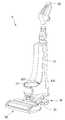
도 1은 본 발명의 제1실시 예에 따른 진공 청소기의 사시도이다.1 is a perspective view of a vacuum cleaner according to a first embodiment of the present invention.
도 1에는 일 예로 업라이트 타입의 진공 청소기에 집진 장치가 장착되는 것이 도시되나, 본 발명의 집진 장치는 캐니스터 타입의 진공 청소기에도 적용될 수 있음을 밝혀둔다.In FIG. 1, for example, a vacuum cleaner of the upright type is shown mounted with a dust collecting device, but the dust collecting device of the present invention can be applied to a vacuum cleaner of a canister type.
도 1을 참조하면, 본 발명의 제1실시 예에 따른 진공 청소기(1)는, 흡입력을 발생시키는 흡입모터를 구비하는 청소기 본체(10)와, 상기 청소기 본체(10)와 연통되며, 먼지를 포함한 공기를 흡입하기 위한 흡입 노즐(20)을 포함할 수 있다.Referring to FIG. 1, a
또한, 상기 진공 청소기(1)는, 상기 흡입 노즐(20)에 대한 청소기 본체(10)의 위치가 가변되도록 하기 위한 서포터(supporter: 30)와, 상기 서포터(30)와 회전 가능하게 연결되는 바퀴 어셈블리(40)를 더 포함할 수 있다.The
상기 서포터(30)의 내부에는 도시되지는 않았으나, 공기가 유동하기 위한 공기 유로가 구비될 수 있다. 따라서, 상기 흡입 노즐(20)을 통하여 흡입된 공기는 상기 서포터(30)를 지나 상기 청소기 본체(10)로 유동할 수 있다.Although not shown in the figure, the
상기 진공 청소기(1)는, 상기 청소기 본체(10)에 분리 가능하게 장착되는 집진 장치(100)를 더 포함할 수 있다.The
상기 집진 장치(100)는, 상기 청소기 본체(10)로 흡입된 공기에서 먼지를 분리시키고, 분리된 먼지가 저장되도록 한다.The
이하에서는 상기 집진 장치(100)에 대해서 상세하게 설명하기로 한다.Hereinafter, the
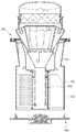
도 2는 본 발명의 제1실시 예에 따른 집진 장치의 사시도이고, 도 3은 도 2의 집진 장치의 단면도이며, 도 4는 본 발명의 제1실시 예에 따른 제2먼지 분리부의 일부 사시도이며, 도 5는 본 발명의 제1실시 예에 따른 집진 장치의 분해 사시도이고, 도 6은 본 발명의 제1실시 예에 따른 필터부를 보여주는 도면이다.FIG. 2 is a perspective view of a dust collecting apparatus according to a first embodiment of the present invention, FIG. 3 is a sectional view of the dust collecting apparatus of FIG. 2, and FIG. 4 is a partial perspective view of a second dust separating unit according to the first embodiment of the present invention FIG. 5 is an exploded perspective view of the dust collecting apparatus according to the first embodiment of the present invention, and FIG. 6 is a view showing a filter unit according to the first embodiment of the present invention.
도 5에는 제2먼지분리부와, 필터 기구 및 배기 커버가 생략된 집진 장치의 분해 사시도가 도시된다.Fig. 5 shows an exploded perspective view of a second dust separator and a dust collecting apparatus in which a filter mechanism and an exhaust cover are omitted.
도 2 내지 도 6을 참조하면, 상기 집진 장치(100)는 집진 바디(110)를 포함할 수 있다. 상기 집진 바디(110)는 제1흡입구(111)를 구비하는 제1먼지 분리부(112)와, 상기 제1먼지 분리부(112)에 의해서 분리된 먼지를 저장하는 제1먼지 저장부(113)를 포함할 수 있다.Referring to FIGS. 2 to 6, the
상기 제1먼지 저장부(113)는 상기 제1먼지 분리부(112)와 일체로 형성되거나, 결합부재에 의해서 상기 제1먼지 분리부(112)에 결합될 수 있다.The first
상기 제1먼지 분리부(112)는 일 예로 원뿔대 형상으로 형성될 수 있고, 상기 제1먼지 저장부(113)는 원통 형상으로 형성될 수 있다. 이 때, 상기 제1먼지 분리부(112)의 직경은 하측으로 갈수록 줄어들 수 있다.The
또는, 상기 제1먼지 분리부(112)가 원통 형상으로 형성되는 것도 가능하다. 본 발명에서 상기 제1먼지 분리부(112)와 상기 제1먼지 저장부(113)의 형상에는 제한이 없음을 밝혀둔다. 다만, 상기 제1먼지 분리부(112)의 하측부 직경은 상기 제1먼지 저장부(113)의 상측부 직경 보다 작을 수 있다.Alternatively, the
상기 제1먼지 분리부(112)의 하측부와 상기 제1먼지 저장부(113)의 상측부의 직경 차이에 의해서 상기 제1먼지 분리부(112)와 상기 제1먼지 저장부(113)는 연결부(114)에 의해서 연결될 수 있다.The first
상기 제1먼지 분리부(112)는 싸이클론 원리에 의해서 공기와 먼지가 분리되도록 할 수 있다.The
상기 제1먼지 분리부(112)로 인입된 공기와 먼지는 상기 제1먼지 분리부(112)의 내주면을 따라 유동하게 되고, 상기 제1먼지 분리부(112)에서 상기 제1먼지 저장부(113)로 진입하게 되면, 상기 제1먼지 저장부(113)의 직경이 상기 제1먼지 분리부(112)의 직경 보다 크기 때문에, 유속이 떨어져 먼지가 상기 제1먼지 저장부(113)에 원활히 집적될 수 있게 된다.The air and dust drawn into the
상기 집진 장치(100)는, 상기 제1먼지 분리부(113)에서 먼지와 분리된 공기를 필터링하기 위한 필터부(120)를 더 포함할 수 있다.The
상기 필터부(120)는, 필터 바디(121)와, 상기 필터 바디(121)에 형성되는 하나 이상의 홀(122)을 포함할 수 있다.The
상기 필터 바디(121)는 후술할 제2먼지 분리부(130)를 지지할 수 있다. 상기 필터 바디(121)의 상측에는 상기 제2먼지 분리부(130)를 지지하기 위한 지지리브(123)가 구비될 수 있다. 상기 지지리브(123)에는 라운드진 지지홈(124)이 구비될 수 있다.The
상기 집진 장치(100)는, 상기 제1먼지 분리부(113)에 의해서 일차적으로 먼지와 분리된 공기를 흡입하고, 흡입된 공기에서 먼지를 재차 분리하기 위한 제2먼지 분리부(130)를 더 포함할 수 있다.The
상기 제2먼지 분리부(130)의 일부는 상기 집진 바디(110) 내측에 위치될 수 있고, 다른 일부는 상기 집진 바디(110) 외측에 위치될 수 있다.A part of the
상기 제2먼지 분리부(130)는 다수의 싸이클론부를 포함할 수 있다. 상기 다수의 싸이클론부는, 다수의 제1싸이클론부(131)와, 상기 다수의 제1싸이클론부(131)가 형성하는 영역 내에 위치하는 하나 이상의 제2싸이클론부(133)를 포함할 수 있다.The
상기 다수의 제1싸이클론부(131)의 싸이클론 유동 축은 상기 하나 이상의 제2싸이클론부(133)의 싸이클론 유동 축과 평행하지 않도록 배치될 수 있다.The cyclone flow axis of the plurality of
일 예로 상기 제2싸이클론부(133)의 싸이클론 유동 축은 수직선과 나란하게 배치될 수 있고, 상기 다수의 제1싸이클론부(131) 각각의 싸이클론 유동 축은 수직선과 경사지게 배치될 수 있다.For example, the cyclone flow axis of the
상기 다수의 제1싸이클론부(131)는 일 예로 링 형태로 배치될 수 있다. 상기 다수의 제1싸이클론부(131)가 링 형태로 배치됨에 따라 상기 다수의 제1싸이클론부(131)가 형성하는 영역 내에 하나 이상의 제2싸이클론부(133)가 위치될 수 있다.The plurality of
본 발명에 의하면, 하나 이상의 제2싸이클론부(133)가 다수의 제1싸이클론부(131) 사이 영역에 위치됨에 따라서, 싸이클론부의 개수를 증가시킬 수 있게 되어, 상기 제2먼지 분리부(130)를 유동하는 공기의 양이 증가될 수 있고, 이에 따라 상기 제2먼지 분리부(130)에서 먼지의 분리 성능이 향상될 수 있다.According to the present invention, as more than one
즉, 공기 유동의 양의 많은 것은 공기 유동이 원활하다는 것을 의미하고, 공기 유동이 원활하면 각 싸이클론부에서 공기와 먼지의 분리 성능이 향상될 수 있다.That is, a large amount of the air flow means that the air flow is smooth, and when the air flow is smooth, separation performance of air and dust in each cyclone portion can be improved.
또한, 본 발명에서 하나 이상의 제2싸이클론부(133)가 다수의 제1싸이클론부(131) 사이 영역에 위치됨에 따라서, 싸이클론부의 개수가 증가되어도 상기 제2먼지 분리부(130)의 크기가 증가하는 것이 방지되고, 컴팩트해질 수 있는 장점이 있다.In addition, according to the present invention, as more than one
상기 각 싸이클론부(131, 133)는 공기가 흡입되는 제2흡입구(132)를 포함할 수 있다.Each of the
상기 필터부(120)를 통과한 공기는 상기 각 싸이클론부(131, 133)의 제2흡입구(132)로 나뉘어 유동할 수 있다. 즉, 상기 다수의 싸이클론부(131, 133)는 병렬로 배치될 수 있다.The air that has passed through the
상기 제1싸이클론부(131)는 상기 필터 바디(121)의 지지부(123)의 지지홈(124)에 안착될 수 있다. 상기 각 싸이클론부(131, 133)의 일부는 상기 필터 바디(121) 내에 수용될 수 있다.The
상기 제2먼지 분리부(130)는, 필터 기구(170)를 지지하기 위한 서포터(136)를 더 포함할 수 있다.The
상기 서포터(136)에는 상기 각 싸이클론부(131, 133)에 삽입되며, 먼지와 분리된 공기의 배출을 가이드하는 공기 가이드(137)가 구비될 수 있다.The
또한, 상기 제2먼지 분리부(130)는, 각 싸이클론부(131, 133)에 공기와 분리된 먼지의 배출을 가이드하는 먼지 배출 가이드(138)를 더 포함할 수 있다. 상기 각 싸이클론부(131, 133)에서 배출된 먼지는 상기 먼지 배출 가이드(138)를 통하여 하방으로 낙하될 수 있다.The
상기 집진 장치(100)는, 상기 제2먼지 분리부(130)에서 배출된 공기를 필터링하는 필터 기구(170)를 더 포함할 수 있다.The
상기 필터 기구(170)는, 필터 프레임(172)과, 상기 필터 프레임(172)에 수용되는 필터(174)를 포함할 수 있다.The
상기 필터 프레임(172)은 상기 제2먼지 분리부(130)에 안착될 수 있다. 일 예로 상기 필터 프레임(172)은 상기 서포터(136)에 안착될 수 있다.The
상기 집진 장치(100)는, 배기 커버(180)를 더 포함할 수 있다. 상기 배기 커버(180)는 상기 제2먼지 분리부(130)의 상측에 안착될 수 있다. 상기 배기 커버(180)는 상기 제2먼지 분리부(130)에 안착된 상태에서 상기 필터 기구(170)를 커버할 수 있다.The
상기 배기 커버(180)는, 공기를 배출시키기 위한 공기 배출구(182)를 포함할 수 있다. 상기 공기 배출구(182)에서 배출된 공기는 상기 청소기 본체(10)로 유입될 수 있다.The
상기 배기 커버(180)에는 상기 제2먼지 분리부(130)에 체결되기 위한 체결부(184)가 구비될 수 있다. 상기 배기 커버(180)는 일 예로 상기 제2먼지 분리부(130)의 서포터(136)에 체결될 수 있다.The
상기 집진 장치(100)는, 상기 제2먼지 분리부(130)에서 분리된 먼지를 저장하는 제2먼지 저장부(150)를 더 포함할 수 있다.The
상기 제2먼지 저장부(150)의 적어도 일부는 상기 제1먼지 저장부(113) 내에 위치될 수 있다.At least a part of the second
상기 제2먼지 저장부(150)는 상기 제2먼지 분리부(130)의 하측에 연결될 수 있다. 일 예로 상기 제2먼지 저장부(150)의 상측에 상기 제2먼지 분리부(130)의 먼지 배출 가이드(138)가 안착될 수 있다.The second
상기 제2먼지 저장부(150)의 일부는 상기 필터부(120) 내에 위치될 수 있다. 일 예로 상기 제2먼지 저장부(150)의 일부는 상기 필터 바디(121) 내에 위치될 수 있다.A part of the second
상기 제2먼지 저장부(150)는, 상기 필터 바디(121) 내에 위치되며, 상기 먼지 배출 가이드(138)와 연결되어 먼지 유입을 가이드하는 먼지 유입 가이드(151)와, 상기 먼지 유입 가이드(151)에서 하방으로 연장되며, 먼지 저장을 위한 공간을 형성하는 저장부 바디(152)를 포함할 수 있다.The second
상기 저장부 바디(152)는 일 예로 원통 형상으로 형성될 수 있으며, 상기 먼지 유입 가이드(151)는 일 예로 원통 또는 원뿔대 형상으로 형성될 수 있다.The
상기 먼지 유입 가이드(151)에는 상기 제2먼지 분리부(130)가 안착되기 위한 안착부(153)가 구비될 수 있다. 또한, 상기 먼지 유입 가이드(151)에는 상기 제2먼지 분리부(130)와 체결되기 위한 체결부(154)가 구비될 수 있다.The
상기 집진 장치(100)는 상기 제1먼지 저장부(113)에 저장된 먼지를 압축하기 압축장치를 더 포함할 수 있다.The
상기 압축장치는, 상기 제1먼지 저장부(113) 내에 회전 가능하게 배치되는 가압부재(200)와, 상기 제1먼지 저장부(113) 내에 위치가 고정된 고정부재(250)를 포함할 수 있다.The compression device may include a
그리고, 상기 가압부재(200)는, 상기 제2먼지 저장부(150)에 회전 가능하게 연결될 수 있다.The pressing
상기 고정부재(250)는 상기 제1먼지 저장부(113)와 일체로 형성되거나, 상기 제1먼지 저장부(113)의 내주면에 위치가 고정되도록 결합될 수 있다.The fixing
상기 가압부재(200)는 상기 제1먼지 저장부(113) 내에서 일 방향 또는 양 방향 회전될 수 있으며, 상기 가압부재(200)의 회전 과정에서 상기 가압부재(200)와 상기 고정부재(250) 사이의 먼지가 압축될 수 있다.The pressing
상기 가압부재(200)는, 중공(211)을 가지는 가압판 지지부(210)와, 상기 가압판 지지부(210)에 지지되는 가압판(220)을 포함할 수 있다.The pressing
상기 가압판(220)은 상기 가압판 지지부(210)와 일체로 형성되거나 상기 가압판 지지부(210)에 결합될 수 있다. 상기 가압판(220)은 상기 가압판 지지부(210)에서 반경 방향으로 연장될 수 있다.The
상기 제2먼지 저장부(150)는 상기 가압판 지지부(210)의 중공(211)에 위치될 수 있다. 이를 위하여, 상기 제2먼지 저장부(150)의 외경은 상기 가압판 지지부(210)의 내경과 동일하거나 작을 수 있다. 도 3에는 일 예로 상기 제2먼지 저장부(150)의 외경이 상기 가압판 지지부(210)의 내경 보다 작은 것이 도시된다.The second
따라서, 상기 가압부재(200)의 회전 과정에서 상기 가압판 지지부(210)가 상기 제2먼지 저장부(150)와 간섭되는 것이 방지될 수 있다.Therefore, it is possible to prevent the
또한, 상기 제2먼지 저장부(150)가 상기 가압판 지지부(210)의 중공(211)에 위치됨에 따라서, 상기 제2먼지 저장부(150)에 먼지를 저장할 수 있을 뿐만 아니라, 상기 제2먼지 저장부(150)에 의한 상기 집진 장치(100)의 체적이나 크기가 커지는 것이 방지될 수 있다.In addition, as the second
상기 가압판(220) 및 상기 고정부재(250) 중 하나 이상에는 상기 가압판(220)이 상기 고정부재(250)를 향하여 회전하는 과정에서 상기 가압판(220)과 상기 고정부재(250) 사이의 공기가 통과하기 위한 하나 이상의 홀(222)을 포함할 수 있다.At least one of the
먼지의 압축 과정에서 상기 제1먼지 저장부(113) 내에 잔류하는 공기가 상기 하나 이상의 홀(222)을 통과할 수 있으므로, 상기 제1먼지 저장부(113)의 공기가 상승함에 따른 먼지의 비산이 최소화되고, 먼지가 제1먼지 분리부(112) 측으로 역류하는 것이 최소화될 수 있다.The air remaining in the first
상기 고정부재(250)는 상기 가압판 지지부(210)와 상기 제1먼지 저장부(113)의 내주면 사이에 위치될 수 있다. 그리고, 상기 고정부재(250)는, 상기 고정부재(250)의 일부와 상기 제1먼지 저장부(113)의 내주면 사이에 공기가 유동할 수 있는 통로(252)를 형성하기 위한 통로 형성부(251)를 포함할 수 있다.The fixing
상기 통로 형성부(251)는 수평선에 대해서 일정 각도 경사지게 배치되며, 직선 또는 라운드 형태일 수 있다. 즉, 상기 통로 형성부(252)(고정부재의 일부)와 상기 제1먼지 저장부(113)의 내주면이 상기 통로(252)를 형성할 수 있다. 또는, 상기 통로 형성부(251)는 상기 고정부재(250)의 일부가 절개된 절개부일 수 있다.The
즉, 상기 통로(252)는, 상기 고정부재(250)에서 상기 가압판 지지부(210)를 바라보는 면과 상기 제1먼지 저장부(113)의 내주면 사이에 위치되어 공기가 통과하도록 할 수 있다.That is, the
상기 통로 형성부(251)에 의해서 상기 고정부재(250)의 전체 높이 중에서 일부 높이에 대해서만 상기 고정부재(250)가 상기 제1먼지 저장부(113)의 내주면과 접촉할 수 있다. 즉, 상기 고정부재(250)에서 상기 통로 형성부(251)가 형성되는 부분의 폭은 상기 통로 형성부(251)가 미형성된 부분의 폭 보다 작게 형성된다.The fixing
상기 통로 형성부(251)는 상기 가압판(220)이 상기 고정부재(250)를 향하여 이동할 때, 상기 가압판(220)과 상기 고정부재(250) 사이의 공기가 상기 고정부재(250)의 외면을 따라 상승하는 것을 최소화시킨다. 즉, 상기 가압판(220)과 상기 고정부재(250) 사이의 공기 및 먼지가 상기 통로 형성부(251)에 의해서 형성된 통로(252)를 통과함에 따라서, 공기 및 먼지가 상기 고정부재(250)의 외면을 따라 상승하는 것이 최소화될 수 있다.The
이 때, 상기 통로 형성부(251)에 의해서 형성되는 통로(252)에 의해서 공기의 상승이 효과적으로 방지되기 위하여, 상기 통로 형성부(251)는 상기 고정부재(250)의 상측부에 형성됨이 바람직하다.At this time, in order to effectively prevent air from rising by the
상기 가압판(220)이 상기 고정부재(250)를 향하여 회전하는 과정에서 상기 제1먼지 저장부(113) 내의 공기가 상승하게 되면, 상기 제1먼지 분리부(112)에서 분리된 먼지가 상기 제1먼지 저장부(113) 측으로 용이하게 인입하기 어려울 수 있다.When the air in the first
따라서, 본 실시 예에서는, 상기 제1먼지 분리부(112)에서 분리된 먼지가 상기 제1먼지 저장부(113) 측으로 용이하게 인입되도록, 상기 필터 바디(121)의 둘레에는 먼지 이동 가이드(129)가 구비된다. 상기 먼지 이동 가이드(129)는 상기 필터 바디(121)에서 하측부에 배치되며, 상기 필터 바디(121)의 외주면 둘레를 따라 나선형으로 형성된다.Therefore, in this embodiment, the dust movement guide 129 (see FIG. 1) is provided around the
그리고, 상기 먼지 이동 가이드(129)는 상기 필터 바디(121)에서 외측으로 갈수록 하향 경사지게 연장될 수 있다. 즉, 상기 먼지 이동 가이드(129)의 단면을 기준으로 상기 먼지 이동 가이드(129)는 상기 필터 바디(121)에서 하향 경사지게 연장된다.The
그리고, 상기 먼지 이동 가이드(129)의 적어도 일부는 상기 제1먼지 저장부(113) 내에 위치될 수 있으며, 상기 제1먼지 분리부(112)와 상기 제1먼지 저장부(113) 각각의 내주면과 이격될 수 있다.At least a part of the
따라서, 본 발명에 의하면, 상기 제1먼지 분리부(112)에서 분리된 먼지는 상기 먼지 이동 가이드(129)를 따라 하방으로 안정적으로 이동하여 상기 제1먼지 저장부(113) 내에 저장될 수 있다.Accordingly, according to the present invention, the dust separated from the
한편, 상기 먼지 이동 가이드(129)는 상기 제1먼지 저장부(113) 내의 공기가 상승하는 경우에, 상승하는 공기 및 먼지의 유동을 제한하기 위한 유동 제한부 역할을 수행할 수 있다.Meanwhile, when the air in the first
또한, 상기 제1먼지 분리부(112)와 상기 제1먼지 저장부(113) 간의 직경 차이에 의해서 형성된 연결부(114)도, 상기 제1먼지 저장부(113) 내의 공기가 상승하는 경우에, 상승하는 공기 및 먼지의 유동을 제한하기 위한 유동 제한부 역할을 수행할 수 있다.The connecting
공기가 제1먼지 저장부(113)에서 상승하는 경우, 일반적으로 공기는 상기 제1먼지 저장부(113)의 내주면을 따라 상승할 수 있다. 상기 연결부(114)는 상기 제1먼지 저장부(113)의 내주면을 따라 상승하는 공기의 유동 저항 역할을 하여, 상승하는 공기의 적어도 일부의 유동 방향을 변화시켜, 상기 제1먼지 저장부(113)로 다시 유동하도록 한다.When air rises in the first
한편, 상기 집진 장치(100)는, 상기 제1먼지 저장부(113)와 상기 제2먼지 저장부(150)를 동시에 개폐하기 위한 커버 조립체(300)를 더 포함할 수 있다.The
상기 커버 조립체(300)는, 상기 제1먼지 저장부(113)를 개폐하는 제1커버(310)를 포함할 수 있다. 상기 제1커버(310)는 상기 집진 바디(110)의 하측에 연결될 수 있다. 이 때, 상기 제1커버(310)는 상기 집진 바디(110)의 하측에 분리 가능하게 연결되거나, 상기 집진 바디(110)의 하측에 힌지에 의해서 회전 가능하게 연결될 수 있다.The
상기 제1커버(310)는, 상기 집진 바디(110)와의 결합을 위한 제1결합리브 (311) 및 제2결합리브(312)를 포함할 수 있다.The
상기 제1결합리브(311) 및 상기 제2결합리브(312) 각각은 상기 제1커버(310)의 상면에서 상방으로 연장될 수 있으며, 원형 링 형태로 형성될 수 있다. 그리고, 상기 제1결합리브(311) 및 상기 제2결합리브(312) 각각은 서로 이격될 수 있다. 상기 집진 바디(110)의 하측은 상기 제1결합리브(311) 및 상기 제2결합리브(312) 사이 간격에 삽입될 수 있다.Each of the first and
따라서, 본 실시 예에 의하면, 상기 집진 바디(110)의 하측이 상기 제1결합리브(311) 및 상기 제2결합리브(312) 사이 간격에 삽입됨에 따라서 별도의 실링부재가 불필요한 장점이 있다.Therefore, according to the present embodiment, since the lower side of the
상기 커버 조립체(300)는, 외부로부터 전달되는 동력을 상기 가압부재(200)로 전달하기 위한 전달기구를 더 포함할 수 있다.The
상기 전달기구는, 상기 제1전달부(330)와 제2전달부(340)를 포함할 수 있다.The transmission mechanism may include the
상기 제1전달부(330)는 상기 제1커버(310)의 일측에 배치되고, 상기 제2전달부(340)는 상기 제1커버(310)의 타측에 배치될 수 있다. 일 예로 상기 제1전달부(330)의 적어도 일부는 상기 제1커버(310)의 하측에 배치되고, 상기 제2전달부(340)의 적어도 일부는 상기 제1커버(310)의 상측에 배치될 수 있다.The
상기 제1전달부(330)는 후술할 구동장치와 연결될 수 있다. 상기 제2전달부(340)는 상기 가압부재(200)와 연결될 수 있다.The
상기 제1커버(310)에는 상기 제1전달부(330)와 상기 제2전달부(340) 중 하나 이상이 관통하기 위한 개구(314)가 구비될 수 있다.The
상기 커버 조립체(300)는 상기 제1전달부(330)를 커버하기 위한 전달부 커버(320)를 더 포함할 수 있다.The
상기 전달부 커버(320)는 상기 제1커버(310)에 체결될 수 있다. 이를 위하여, 상기 제1커버(310)에는 제1체결홀(315)이 형성되고, 상기 전달부 커버(320)에는 제2체결홀(325)이 형성될 수 있다. 이 때, 상기 전달부 커버(320)는 상기 제1커버(310)의 하측에 체결될 수 있다.The
상기 전달부 커버(320)는 상기 제1전달부(330)를 지지하기 위한 지지부(322)를 포함할 수 있다. 상기 지지부(322)는 상기 전달부 커버(320)의 일부가 하방으로 함몰됨에 따라 형성될 수 있다.The
상기 지지부(322)에는 상기 제1전달부(330)를 관통하는 샤프트(326)가 구비될 수 있다. 상기 제1전달부(330)는 상기 샤프트(326)를 중심으로 회전할 수 있다. 상기 샤프트(326)는 상기 제2전달부(340)도 관통할 수 있다.The
상기 전달부 커버(320)는 상기 제1전달부(330)가 외부로 노출되기 위한 노출부(324)를 더 포함할 수 있다. 상기 노출부(324)는 일 예로 상기 제1전달부(322)의 일부가 절개되어 형성되는 절개부일 수 있다.The
상기 커버 조립체(300)는 상기 제2먼지 저장부(150)를 개폐하는 제2커버(350)를 더 포함할 수 있다. 상기 제2커버(350)가 상기 제2먼지 저장부(150)를 닫은 상태에서 상기 제2커버(350)는 상기 가압부재(200)의 가압판 지지부(210) 내에 위치될 수 있다.The
상기 제2커버(350)가 상기 가압판 지지부(210) 내에 위치되면, 상기 가압판 지지부(210)와 상기 제2커버(350)의 간섭이 방지될 뿐만 아니라, 상기 가압판 지지부(210)가 실링 벽 역할을 할 수 있다.When the
상기 제2먼지 저장부(150)의 먼지가 상기 제2먼지 저장부(150) 외부로 누설되는 것을 방지하기 위하여, 실링부재(360)가 상기 제2커버(350) 또는 상기 제2먼지 저장부(150)에 결합될 수 있다. 도 3에는 일 예로 상기 실링부재(360)가 상기 제2먼지 저장부(150)에 결합된 것이 도시된다.The sealing
도 7은 도 3의 A 부분의 확대도이다.7 is an enlarged view of a portion A in Fig.
도 3 및 도 7을 참조하면, 상기 필터부(120)에는 상기 제2먼지 저장부(150)가 관통하기 위한 홀(125)이 형성될 수 있다.3 and 7, the
상기 필터부(120)의 하측에는 상기 가압부재(200)의 가압판 지지부(210)의 상단부가 삽입되기 위한 수용홈(127)이 형성될 수 있다. 상기 가압판 지지부(210)에는 상기 가압판 지지부(210)가 상기 수용홈(127)에 수용된 상태에서 상기 수용홈(127)을 형성하는 벽(128)을 수용하기 위한 수용홈(213)을 구비하는 벽 서포터(214)가 구비될 수 있다.A receiving
따라서, 상기 필터부(120)의 수용홈(127)에 상기 가압판 지지부(210)의 상단부가 삽입되고, 상기 가압판 지지부(210)의 벽 서포터(214)의 수용홈(213)에 상기 필터부(120)에서 연장되는 벽(128)이 삽입됨에 따라, 2중 실링 구조가 형성되어 상기 제1먼지 저장부(113)의 먼지가 상기 가압판 지지부(210)와 상기 제2먼지 저장부(150) 사이로 인입되는 것이 방지될 수 있다.The upper end of the pressing
즉, 본 발명에서, 수용홈(127, 213), 벽(128) 및 벽 서포터(214)를 실링 기구라 이름할 수 있다.That is, in the present invention, the receiving
상기 가압판 지지부(210)와 상기 제2먼지 저장부(150) 사이로 먼지가 인입되는 것이 방지됨에 따라서, 상기 가압판 지지부(210)가 상기 가압판 지지부(210)와 상기 제2먼지 저장부(150) 사이의 먼지에 의해서 원활히 회전되지 못하는 현상이 방지될 수 있다.It is possible to prevent dust from entering between the
상기 가압판 지지부(210)의 내주면과 상기 제2먼지 저장부(150)의 외주면 중 어느 하나에는 결합돌기(212)가 형성될 수 있고, 다른 하나에는 상기 결합돌기(212)가 삽입되기 위한 결합홈(156)이 형성될 수 있다. 상기 결합돌기(212)는 상기 가압판 지지부(210)에 상기 제2먼지 저장부(150)가 삽입되는 과정에서 탄성 변형되고, 상기 결합홈(156)과 정렬되면, 상기 결함홈(156)에 삽입될 수 있다.The
다른 예로서, 상기 가압판 지지부(210) 및 상기 제2먼지 저장부(150)와 별도로 형성된 결합핀이 상기 가압판 지지부(210)의 외측에서 상기 가압판 지지부(210)를 관통하여 상기 제2먼지 저장부(150)에 형성된 결합홈(156)에 삽입되는 것도 가능하다. 또는, 상기 가압판 지지부(210) 및 상기 제2먼지 저장부(150)와 별도로 형성된 결합핀이 상기 제2먼지 저장부(150) 내측에서 상기 제2먼지 저장부(150)를 관통하여 상기 가압판 지지부(210)에 형성된 결합홈(156)에 삽입되는 것도 가능하다.As another example, an engagement pin formed separately from the pressure
이 때, 어느 경우든, 상기 제2먼지 저장부(150)에 상기 가압판 지지부(210)가 연결된 상태에서 상기 가압판 지지부(210)가 회전되기 위하여, 상기 결합홈(156)은 상기 가압판 지지부(210) 또는 상기 제2먼지 저장부(150)의 원주 방향을 따라 링 형상으로 형성될 것이다.In this case, in order to rotate the pressing
본 실시 예에 의하면, 상기 커버 조립체(300)를 상기 집진 바디(110)와 분리시킨 상태에서 상기 가압판 지지부(210)가 상기 제2먼지 저장부(150)에 결합된 상태를 유지하므로, 상기 가압부재(200)가 상기 제1먼지 저장부(113) 내에 위치한 상태가 유지된다. 즉, 상기 커버 조립체(300)가 상기 집진 바디(110)에서 분리된 상태에서 상기 가압부재(200)가 상기 집진 바디(110) 내에서 빠지는 것이 방지될 수 있다.According to the present embodiment, since the
도 8은 도 3의 B부분의 확대도이다.8 is an enlarged view of a portion B in Fig.
도 3, 도 5 및 도 8을 참조하면, 상기 제2먼지 저장부(150)의 하측에는 상기 실링부재(360)가 결합될 수 있다. 상기 실링부재(360)는 상기 제2먼지 저장부(150)와 결합되기 위한 결합부(361)를 포함하고, 상기 제2먼지 저장부(150)의 외주면에는 상기 결합부(361)의 일부가 삽입되기 위한 홈(158)이 형성될 수 있다. 상기 실링부재(360)는 상기 제2먼지 저장부(150)의 둘레를 감쌀 수 있다.3, 5, and 8, the sealing
다른 예로 상기 결합부(361)가 상기 제2먼지 저장부(150)에 억지끼움 형태로 삽입될 수 있다.As another example, the
상기 실링부재(360)는 상기 커버 조립체(300)가 상기 집진 바디(110)와 결합된 상태에서 상기 제2커버(350)의 상측에 안착되는 안착부(362)를 더 포함할 수 있다. 상기 안착부(362)는 상기 제2커버(350)와 면접촉하며, 상기 제2커버(350)의 외측 둘레를 감쌀 수 있다. 다른 측면에서 설명하면, 상기 제2커버(350)의 일부는 상기 실링 부재(360)에 삽입될 수 있다.The sealing
그리고, 상기 실링부재(360)에는 상기 제2먼지 저장부(150) 내의 먼지가 통과하기 위한 관통홀(363)이 형성될 수 있다. 따라서, 상기 제2먼지 저장부(150) 내의 먼지 일부는 상기 제2커버(350) 상에 쌓일 수 있다.The sealing
상기 실링부재(360)는 일 예로 형상이 변형 가능한 재질로 형성될 수 있다. 상기 실링부재(360)는 일 예로 고무 재질로 형성될 수 있다.The sealing
본 실시 예에 의하면, 상기 실링부재(360)가 상기 제2커버(350)와 면접촉되어 상기 제2커버(350)의 둘레를 감싸므로, 상기 제2먼지 저장부(150)에 저장된 먼지가 상기 제2먼지 저장부(150) 외측으로 누설되는 것이 방지될 수 있다.Since the sealing
상기 제1전달부(330)는 상기 제2전달부(340)에 삽입되기 위한 삽입부(332)를 포함하고, 상기 제2전달부(340)는 상기 삽입부(332)가 삽입되는 수용부(343)를 포함할 수 있다.The
상기 삽입부(332)에는 상기 제2전달부(340)의 체결홀(344)을 관통한 체결부재(S1)가 체결되는 체결홈(333)이 형성될 수 있다.The
따라서, 상기 제1전달부(330)가 회전되면, 상기 제2전달부(340)도 함께 회전될 수 있다.Accordingly, when the
상기 제2전달부(340)가 회전력을 상기 가압판 지지부(210)로 전달하기 위하여, 상기 가압판 지지부(210)와 상기 전달부(340) 중 어느 하나는 전달돌기(214)를 포함하고, 다른 하나는 전달돌기(214)가 수용되는 수용홈(342)을 포함할 수 있다.One of the pressing
도 8에는 일 예로 상기 전달돌기(214)가 상기 가압판 지지부(210)에 형성되고, 상기 수용홈(342)이 제2전달부(340)에 형성되는 것이 도시된다. 이 경우, 상기 전달돌기(214)는 일 예로 상기 가압판 지지부(210)의 외주면에서 돌출될 수 있다. 상기 가압판 지지부(210)의 외주면에서 돌출된 상기 전달돌기(214)가 상기 제2전달부(340)의 수용홈(342)에 수용되기 위하여, 상기 제2전달부(340)의 일부는 상기 가압판 지지부(210)에 삽입될 수 있다.In FIG. 8, for example, the
다른 예로서, 상기 전달돌기(214)가 상기 가압판 지지부(210)의 하면에서 하방으로 돌출될 수 있다. 이 경우에는 상기 제2전달부(340)의 일부가 상기 가압판 지지부(210)에 수용되지 않은 상태에서 상기 전달돌기(214)가 상기 제2전달부(340)의 수용홈(342)에 수용되는 것이 가능하다.As another example, the
상기 제2커버(350)는 체결부재(S2)에 의해서 상기 전달부 커버(320)의 샤프트(326)에 체결될 수 있다. 따라서, 상기 제1전달부(330) 및 상기 제2전달부(340)가 회전되더라도 상기 제2커버(350)는 정지된 상태를 유지할 수 있다.The
상기 제1먼지 저장부(113) 내의 먼지 및 공기가 상기 제2전달부(340)와 상기 제1커버(310) 사이를 통하여 외부로 누설되는 것을 방지하기 위하여, 상기 제2전달부(340)와 상기 제1커버(310) 중 하나 이상에는 제1실링부(371)가 구비될 수 있다. 상기 제1실링부(371)는 일 예로 오링일 수 있다.In order to prevent the dust and air in the first
일 예로 도 8에는 제1실링부(371)가 상기 제2전달부(340)에 구비되는 것이 도시된다. 이 경우, 상기 제2전달부(340)에는 상기 제1실링부(371)가 수용되기 위한 제1홈(348)이 구비될 수 있다.For example, in FIG. 8, a
상기 제2커버(350)에서 상기 제2전달부(340)의 마주보는 부분에는 제2실링부(372)가 구비될 수 있다. 상기 제2실링부(372)는 일 예로 오링일 수 있다.A
상기 제2실링부(372)는 상기 제1먼지 저장부(113)의 공기 및 먼지가 상기 제2커버(350)와 상기 제2전달부(340) 사이 틈새를 통과하는 것을 방지할 수 있다.The
또한, 상기 제2실링부(372)는 상기 제2먼지 저장부(150)와 가압판 지지부(210) 사이에 존재할 수 있는 먼지 및 공기가 상기 제2커버(350)와 상기 제2전달부(340) 사이 틈새를 통과하는 것을 방지할 수 있다.The
도 9는 도 1의 진공 청소기에서 집진 장치가 분리된 상태를 보여주는 도면이다.FIG. 9 is a view showing a state in which the dust collecting apparatus is separated from the vacuum cleaner of FIG. 1;
도 5 및 도 9를 참조하면, 상기 청소기 본체(10)는, 상기 가압부재(200)를 구동하기 위한 구동장치(410, 420)를 포함할 수 있다. 상기 구동장치(410, 420)는, 구동 모터(410)와, 상기 구동 모터(410)와 연결되는 구동 기어(420)를 포함할 수 있다.Referring to FIGS. 5 and 9, the
상기 청소기 본체(10)에는 상기 집진 장치(100)가 장착되기 위한 장착부(13)가 구비되며, 상기 구동 기어(420)는 상기 장착부(13)로 노출될 수 있다.The cleaner
상기 구동 기어(420)는 상기 제1전달부(330)로 상기 구동 모터(410)의 동력을 전달할 수 있다. 상기 제1전달부(330)가 상기 구동 기어(420)로부터 상기 구동 모터(410)의 동력을 전달받기 위하여, 상기 제1전달부(330)는 일 예로 기어일 수 있다.The
그리고, 상기 집진 장치(100)가 상기 청소기 본체(10)의 장착부(13)에 장착되면, 상기 제1전달부(330)가 상기 구동 기어(420)와 연결될 수 있다. 반면, 상기 집진 장치(100)가 상기 청소기 본체(10)로부터 분리되면, 상기 제1전달부(330)와 상기 구동 기어(420)의 연결은 해제될 수 있다.When the
도 10은 본 발명의 일 실시 예에 따른 집진 장치 내에서의 공기 및 먼지의 이동 모습을 보여주는 도면이다.10 is a view showing the movement of air and dust in the dust collecting apparatus according to an embodiment of the present invention.
도 1 내지 도 10을 참조하면, 청소기 본체(10)에 구비되는 흡입 모터가 작동하면, 흡입 모터의 흡입력에 의해서 상기 흡입 노즐(20)을 통하여 공기와 먼지가 흡입된다. 상기 흡입 노즐(20)을 통하여 흡입된 공기와 먼지를 상기 서포터(30)를 지난 후에 상기 청소기 본체(10)로 유입된다. 상기 청소기 본체(10)를 유동하는 먼지와 공기는 상기 집진 장치(100)로 유입된다.Referring to FIGS. 1 to 10, when the suction motor provided in the cleaner
즉, 상기 집진 장치(100)의 제1흡입구(111)를 통하여 공기와 먼지가 상기 집진 장치(100)로 유입된다. 상기 제1흡입구(111)를 통과한 공기와 먼지는 상기 제1먼지 분리부(112)로 유입되고, 상기 제1먼지 분리부(112)로 유입된 공기와 먼지는 싸이클론 유동에 의해서 상호 분리된다.That is, air and dust are introduced into the
그리고, 공기에서 일차적으로 분리된 먼지는 하방으로 이동하여 상기 제1먼지 저장부(113)에 저장된다. 반면, 먼지와 분리된 공기는 상기 필터부(120)의 홀(122)을 통과한 후에 상승하고, 상기 제2먼지 분리부(130)의 제2흡입구(132)를 통하여 상기 제2먼지 분리부(130)로 유입된다. 즉, 상기 제1먼지 분리부(112)에서 먼지 분리 과정을 거친 공기는 상기 다수의 제1싸이클론부(131)와, 하나 이상의 제2싸이클론부(133)로 나뉘어 유동하게 된다.In addition, the dust primarily separated from the air moves downward and is stored in the first
상기 제2먼지 분리부(130)로 인입된 공기는 싸이클론 유동 과정에서 먼지와 재차 분리된다. 상기 제2먼지 분리부(130) 내에서 공기와 분리된 먼지(점선 참조)는 상기 제2먼지 분리부(130)에서 배출된 후에 상기 제2먼지 저장부(150)에 저장된다.The air drawn into the
반면, 상기 제2먼지 분리부(130) 내에서 먼지와 분리된 공기는 공기 가이드(137)를 통하여 상기 각 싸이클론부(131, 133)에서 배출된다.On the other hand, the air separated from the dust in the
상기 각 싸이클론부(131, 133)에서 배출된 공기는 상기 필터(174)를 통과한 후에 최종적으로 상기 배기 커버(180)의 공기 배출구(182)를 통하여 상기 집진 장치(100)에서 배출된다. 상기 집진 장치(100)에서 배출된 공기는 상기 청소기 본체(10)로 유입된 후에 상기 청소기 본체(10)에서 외부로 배출될 수 있다.The air discharged from each of the
한편, 상기 흡입 모터가 작동하는 중에는 상기 구동 모터(410)가 작동할 수 있다. 상기 구동 모터(410)가 작동하면, 상기 구동 기어(420)가 일 방향으로 회전할 수 있다. 상기 구동 기어(420)가 일 방향으로 회전하면, 상기 구동 기어(420)의 회전력에 의해서 상기 제1전달부(330)가 타 방향으로 회전할 수 있다.Meanwhile, the
그러면, 상기 제1전달부(330)와 동일한 방향으로 상기 제2전달부(340)가 회전되고, 상기 제2전달부(340)와 동일한 방향으로 상기 가압부재(200)가 회전할 수 있다.The
그리고, 상기 가압부재(200)의 회전에 의해서 상기 가압부재(200)의 가압판(220)과 상기 고정부재(250) 사이의 먼지(제1먼지 저장부의 먼지임)가 압축될 수 있다.The dust between the
따라서, 본 실시 예에 의하면, 상기 제1먼지 저장부 내에 저장된 먼지가 가압부재에 의해서 압축될 수 있으므로, 상기 제1먼지 저장부에 저장된 먼지의 부피가 줄어들게 되어 상기 제1먼지 저장부의 먼지 저장용량이 증가될 수 있고, 먼지가 압축된 상태로 상기 제1먼지 저장부에 저장되므로, 먼지의 배출 과정에서 먼지의 비산 현상이 방지될 수 있다.Therefore, according to the present embodiment, since the dust stored in the first dust storage unit can be compressed by the pressing member, the volume of the dust stored in the first dust storage unit is reduced and the dust storage capacity of the first dust storage unit Can be increased and the dust is stored in the first dust storage portion in a compressed state, so that dust scattering phenomenon can be prevented in the discharge process of the dust.
또한, 상기 가압부재(200)의 회전 과정에서 가압판(220)과 상기 고정부재(250) 사이의 공기는 상기 통로(252)를 통과할 수 있다. 따라서, 상기 가압판(220)이 먼지를 압축하는 과정에서 상기 가압판(220)과 상기 고정부재(250) 사이의 공기 및 먼지가 상기 고정부재(250)의 외면을 따라 상승하는 것이 최소화될 수 있다.In addition, in the rotation process of the
상기 가압부재(200)의 회전 과정에서 상기 가압부재(200)는 회전 방향은 변화될 수 있다. 상기 가압부재(200)의 회전 방향이 바뀌는 방법은 공지의 기술에 의해서 구현될 수 있으므로, 자세한 설명은 생략하기로 한다.The rotational direction of the
도 11은 본 발명의 제1실시 예에 따른 집진 장치에서 커버 조립체가 분리된 상태를 보여주는 도면이다.11 is a view illustrating a state in which the cover assembly is separated in the dust collecting apparatus according to the first embodiment of the present invention.
도 11을 참조하면, 상기 제1먼지 저장부(113) 및 상기 제2먼지 저장부(150)에 저장된 먼지를 비우기 위하여, 상기 커버 조립체(300)를 상기 집진 장치(100)로부터 분리할 수 있다.11, the
그러면, 상기 제1먼지 저장부(113) 및 상기 제2먼지 저장부(150)에 저장된 먼지는 상기 집진 바디(110)의 하방으로 낙하될 수 있다. 상술한 바와 같이 상기 상기 커버 조립체(300)를 상기 집진 장치(100)로부터 분리한 상태에서 상기 가압부재(200)는 상기 제1먼지 저장부(113) 내에 위치한 상태를 유지한다.
Then, the dust stored in the first
도 12는 본 발명의 제2실시 예에 따른 필터부를 보여주는 도면이다.12 is a view illustrating a filter unit according to a second embodiment of the present invention.
본 실시 예는 다른 부분에 있어서는 제1실시 예와 동일하고, 다만, 먼지 이동 가이드에 있어서 차이가 있다. 따라서, 이하에서는 본 실시 예의 특징적인 부분에 대해서만 설명하기로 한다.The present embodiment is the same as the first embodiment in other portions, but differs in the dust movement guide. Therefore, only the characteristic parts of the present embodiment will be described below.
도 12를 참조하면, 본 실시 예에 따른 필터부(120)는, 필터 바디(121)의 둘레에서 연장되는 먼지 이동 가이드(129a)를 포함할 수 있다.Referring to FIG. 12, the
상기 먼지 이동 가이드(129a)는 상기 필터 바디(121)에서 하측부에 배치되며, 상기 필터 바디(121)의 외주면 둘레를 따라 나선형으로 형성될 수 있다.The
그리고, 상기 먼지 이동 가이드(129a)는 상기 필터 바디(121)에서 수직하게 연장될 수 있다. 즉, 상기 먼지 이동 가이드(129a)는 수평 단면이 수평선과 나란하게 연장될 수 있다.The
본 실시 예에 의해서도, 상기 제1먼지 분리부(112)에서 분리된 먼지는 상기 먼지 이동 가이드(129a)를 따라 하방으로 안정적으로 이동하여 상기 제1먼지 저장부(113) 내에 저장될 수 있다.Also in this embodiment, the dust separated from the
또한, 본 실시 예의 먼지 이동 가이드(129a)도 제1실시 예에서 설명한 유동 제한부의 역할을 수행할 수 있다.
In addition, the
도 13은 본 발명의 제3실시 예에 따른 필터부를 보여주는 도면이다.13 is a view illustrating a filter unit according to a third embodiment of the present invention.
본 실시 예는 다른 부분에 있어서는 제1실시 예와 동일하고, 다만, 먼지 이동 가이드에 있어서 차이가 있다. 따라서, 이하에서는 본 실시 예의 특징적인 부분에 대해서만 설명하기로 한다.The present embodiment is the same as the first embodiment in other portions, but differs in the dust movement guide. Therefore, only the characteristic parts of the present embodiment will be described below.
도 13을 참조하면, 본 실시 예에 따른 필터부(520)는, 하나 이상의 홀(522)을 구비하는 필터 바디(521)를 포함할 수 있다.Referring to FIG. 13, the
본 실시 예의 필터 바디(521)의 기본 기능은, 제1실시 예의 필터 바디(121)와 동일하다.The basic function of the
상기 필터부(520)는, 상기 필터 바디(521)의 외주면과 이격된 상태에 상기 필터 바디(521)의 둘레를 감싸는 먼지 이동 가이드(524)를 포함할 수 있다. 따라서, 상기 먼지 이동 가이드(524)와 상기 필터 바디(521)의 외주면은 먼지가 유동하기 위한 먼지 유로(525)를 형성한다.The
따라서, 제1먼지 분리부에서 분리된 먼지를 먼지 이동 가이드(524)에 의해서 형성된 먼지 유로(525)를 따라 유동하다가 하방으로 낙하될 수 있다.Accordingly, the dust separated by the first dust separating unit flows along the
그리고, 상기 먼지 이동 가이드(524)의 하단에는 제1먼지 저장부(113) 내의 먼지 및 공기가 상승하는 것을 제한하기 위한 유동 제한부(526)가 구비될 수 있다. 상기 유동 제한부(526)는 상기 먼지 이동 가이드(524)의 하단에서 상기 필터 바디(521)와 멀어지는 방향으로 연장될 수 있다.The lower end of the
본 실시 예에 의하면, 상기 먼지 이동 가이드(524)가 먼지 유로(525)를 형성함에 따라서, 먼지 유로(525) 상의 먼지가 제1먼지 저장부(113) 내의 공기의 영향을 받지 않고 원활히 하방으로 이동할 수 있는 장점이 있다.
According to the present embodiment, as the
도 14는 본 발명의 제4실시 예에 따른 집진 장치를 보여주는 단면도이고, 도 15는 도 14의 먼지 이동 가이드를 보여주기 위한 집진 바디의 평면도이다.FIG. 14 is a sectional view showing a dust collecting apparatus according to a fourth embodiment of the present invention, and FIG. 15 is a plan view of a dust collecting body for showing the dust moving guide of FIG.
본 실시 예는 다른 부분에 있어서는 제1실시 예와 동일하고, 다만, 먼지 이동 가이드의 위치에 있어서 차이가 있다. 따라서, 이하에서는 본 실시 예의 특징적인 부분에 대해서만 설명하기로 한다.The present embodiment is the same as the first embodiment in other portions, but differs in the position of the dust movement guide. Therefore, only the characteristic parts of the present embodiment will be described below.
도 14 및 도 15를 참조하면, 본 실시 예에 따른 제1먼지 저장부(113)는 먼지 이동 가이드(530)를 포함할 수 있다.Referring to FIGS. 14 and 15, the first
상기 먼지 이동 가이드(530)는 제1먼지 분리부(112)에서 분리된 먼지가 상기 제1먼지 저장부(113)의 하측으로 용이하게 이동하도록 가이드할 수 있다.The
상기 먼지 이동 가이드(530)는 상기 제1먼지 저장부(113)의 내주면과 일체로 형성되거나, 상기 제1먼지 저장부(113)의 내주면에 결합될 수 있다. 상기 먼지 이동 가이드(530)는 상기 제1먼지 저장부(113)의 내주면에서 돌출될 수 있다.The
그리고, 상기 먼지 이동 가이드(530)는 상기 제1먼지 저장부(113)의 내주면에서 원주 방향으로 소정 길이 연장될 수 있다. 그리고, 상기 먼지 이동 가이드(530)는 고정부재(250) 및 가압판(220) 보다 높게 위치될 수 있다. 그리고, 상기 먼지 이동 가이드(530)의 적어도 일부는 상기 고정부재(250)와 상하 방향으로 중첩되도록 배치될 수 있다.The
상기 먼지 이동 가이드(530)는, 상기 제1먼지 저장부(113)로 이동한 먼지를 초기에 가이드하는 제1가이드(532)를 포함할 수 있다. 상기 제1가이드(532)는 상기 제1먼지 저장부(113)의 내주면에서 상하 방향으로 경사지게 연장될 수 있다.The
상기 먼지 이동 가이드(530)는 상기 먼지 이동 가이드(530)를 따라서 유동하는 먼지가 낙하되도록 하기 위한 낙하 단부(534)를 포함할 수 있다. 상기 낙하 단부(534)는 상기 제1가이드(532)와 이격되며, 상기 제1가이드(532) 보다 낮게 위치할 수 있다.The
상기 제1먼지 저장부(113)로 이동한 먼지는 상기 제1가이드(532)에 의해서 상기 먼지 이동 가이드(530)의 상면으로 이동하고, 상기 먼지 이동 가이드(530)의 상면을 따라 유동하는 먼지는 상기 낙하 단부(534)에 의해서 상기 먼지 이동 가이드(530)에서 낙하될 수 있다.The dust moved to the first
상기 먼지 이동 가이드(530)가 상기 제1먼지 저장부(113)의 내주면에 구비됨에 따라서, 상기 먼지 이동 가이드(530)는 상기 제1먼지 저장부(113) 내에서 상승하는 공기의 상승을 제한하는 유동 제한부 역할을 할 수 있다.
As the
도 16은 본 발명의 제5실시 예에 따른 집진 장치를 보여주는 단면도이고, 도 17은 도 16의 먼지 이동 가이드를 보여주기 위한 집진 바디의 평면도이다.FIG. 16 is a sectional view showing a dust collecting apparatus according to a fifth embodiment of the present invention, and FIG. 17 is a plan view of a dust collecting body for showing the dust moving guide of FIG.
본 실시 예는 다른 부분에 있어서는 제4실시 예와 동일하고, 다만, 먼지 분리부와 먼지 저장부의 크기에 있어서 차이가 있다. 따라서, 이하에서는 본 실시 예의 특징적인 부분에 대해서만 설명하기로 한다.The present embodiment is the same as the fourth embodiment in the other portions, but there is a difference in the size of the dust separator and the dust reservoir. Therefore, only the characteristic parts of the present embodiment will be described below.
도 16 및 도 17을 참조하면, 본 실시 예에 따른 제1먼지 분리부(112)의 수직 중심(C1)과 제1먼지 저장부(113)의 수직 중심(C2)은 편심될 수 있다.16 and 17, the vertical center C1 of the first
그리고, 상기 제1먼지 저장부(113)는 먼지 이동 가이드(540)를 포함할 수 있다.The first
상기 먼지 이동 가이드(540)는 제1먼지 분리부(112)에서 분리된 먼지가 상기 제1먼지 저장부(113)의 하측으로 용이하게 이동하도록 가이드할 수 있다.The
상기 먼지 이동 가이드(540)는 상기 제1먼지 저장부(113)의 내주면과 일체로 형성되거나, 상기 제1먼지 저장부(113)의 내주면에 결합될 수 있다. 그리고, 상기 먼지 이동 가이드(540)는 상기 제1먼지 저장부(113)의 내주면에서 원주 방향으로 소정 길이 연장될 수 있다. 그리고, 상기 먼지 이동 가이드(540)는 고정부재(250) 및 가압판(220) 보다 높게 위치될 수 있다.The
상기 먼지 이동 가이드(540)는, 상기 제1먼지 저장부(113)로 이동한 먼지를 초기에 가이드하는 제1가이드(542)를 포함할 수 있다. 상기 제1가이드(542)는 상기 제1먼지 저장부(113)의 내주면에서 상하 방향으로 경사지게 연장될 수 있다.The
상기 먼지 이동 가이드(540)는 상기 먼지 이동 가이드(540)를 따라서 유동하는 먼지가 낙하되도록 하기 위한 낙하 단부(544)를 포함할 수 있다. 상기 낙하 단부(544)는 상기 제1가이드(542)와 이격되며, 상기 제1가이드(542) 보다 낮게 위치할 수 있다.The
상기 제1먼지 저장부(113)로 이동한 먼지는 상기 제1가이드(542)에 의해서 상기 먼지 이동 가이드(540)의 상면으로 이동하고, 상기 먼지 이동 가이드(540)의 상면을 따라 유동하는 먼지는 상기 낙하 단부(544)에 의해서 상기 먼지 이동 가이드(540)에서 낙하될 수 있다.The dust moved to the first
상기 먼지 이동 가이드(540)가 상기 제1먼지 저장부(113)의 내주면에 구비됨에 따라서, 상기 먼지 이동 가이드(540)는 상기 제1먼지 저장부(113) 내에서 상승하는 공기의 상승을 제한하는 유동 제한부 역할을 할 수 있다.
As the
도 18은 본 발명의 제6실시 예에 따른 집진 장치를 보여주는 단면도이다.18 is a sectional view showing a dust collecting apparatus according to a sixth embodiment of the present invention.
본 실시 예는 다른 부분에 있어서는 제1실시 예와 동일하고, 다만, 제2먼지 저장부의 위치에 있어서 차이가 있다. 따라서, 이하에서는 본 실시 예의 특징적인 부분에 대해서만 설명하기로 한다.The present embodiment is the same as the first embodiment in other portions, but differs in the position of the second dust storage portion. Therefore, only the characteristic parts of the present embodiment will be described below.
도 18을 참조하면, 본 실시 예의 집진 장치(100)는 집진 바디(110)를 포함할 수 있다. 상기 집진 바디(110)는, 제1먼지 분리부(112)와, 상기 제1먼지 분리부(112)의 하측에 위치되는 제1먼지 저장부(113)를 포함할 수 있다.Referring to FIG. 18, the
상기 제1먼지 저장부(113)에는 제2먼지 저장부(150a)가 위치될 수 있다. 이 때, 상기 제2먼지 저장부(150a)는 상기 가압판 지지부(210)와 제1먼지 저장부(113)의 내주면 사이에 위치될 수 있다.The second dust storage part (150a) may be located in the first dust storage part (113). At this time, the second
상기 제2먼지 저장부(150a)는 상기 가압판 지지부(210)와 이격될 수 있다. 상기 제2먼지 저장부(150a)는 상기 제1먼지 저장부(113)의 내주면과 이격될 수 있다.The second
본 실시 예에 의하면, 상기 제2먼지 저장부(150a)가 제1실시 예의 고정부재 역할을 수행할 수 있다. 반대로 설명하면, 고정부재가 먼지를 저장하는 제2먼지 저장부 역할을 할 수 있다.According to the present embodiment, the second
이 경우, 상기 제2먼지 저장부(150a)의 외면이 통로 형성부 역할을 한다. 그리고, 상기 제2먼지 저장부(150a)의 외면 전부는 상기 제1먼지 저장부(113)의 내면과 이격될 수 있다.In this case, the outer surface of the second
그리고, 상기 제2먼지 저장부(150a)가 상기 제1먼지 저장부(113)의 내주면과 이격됨에 따라서 상기 제2먼지 저장부(150a)의 외면과 상기 제1먼지 저장부(113)의 내주면 사이에 통로(252a)가 형성될 수 있다.As the second
상기 집진 장치(100)는, 상기 제1먼지 저장부(113)와 제2먼지 저장부(150a)를 동시에 개폐하는 제1커버(310)를 더 포함할 수 있다. 그리고, 상기 제1커버(310)에는 상기 제2먼지 저장부(150a)를 커버하기 위한 커버부(350a)가 구비될 수 있다. 상기 커버부(350a)는 상기 제1커버(310)에서 상방으로 돌출될 수 있으며, 상기 제2먼지 저장부(150a)에 삽입될 수 있다.
The
본 명세서에서는 집진 장치가 제1먼지 분리부, 제2먼지 분리부와, 제1먼지 저장부 및 제2먼지 저장부를 구비하는 경우에 대해서 설명하였으나, 이와 달리, 집진 바디의 형상, 필터부에 구비되는 먼지 이동 가이드, 고정부재에 의해서 형성되는 통로, 제1먼지 저장부에 구비되는 먼지 이동 가이드에 대한 내용은 상기 집진 장치가 하나의 먼지 분리부와 하나의 먼지 저장부를 구비하는 경우에도 동일하게 적용될 수 있음을 밝혀둔다.
In the present specification, the case where the dust collecting apparatus includes the first dust separating unit, the second dust separating unit, the first dust storing unit and the second dust storing unit has been described. Alternatively, the shape of the dust collecting body, The dust transfer guide provided in the first dust storage portion is equally applicable to a case in which the dust collector has one dust separator and one dust reservoir .
이상에서, 본 발명의 실시예를 구성하는 모든 구성 요소들이 하나로 결합하거나 결합하여 동작하는 것으로 설명되었다고 해서, 본 발명이 반드시 이러한 실시예에 한정되는 것은 아니다. 즉, 본 발명의 목적 범위 안에서라면, 그 모든 구성 요소들이 하나 이상으로 선택적으로 결합하여 동작할 수도 있다. 또한, 이상에서 기재된 "포함하다", "구성하다" 또는 "가지다" 등의 용어는, 특별히 반대되는 기재가 없는 한, 해당 구성 요소가 내재할 수 있음을 의미하는 것이므로, 다른 구성 요소를 제외하는 것이 아니라 다른 구성 요소를 더 포함할 수 있는 것으로 해석되어야 한다. 기술적이거나 과학적인 용어를 포함한 모든 용어들은, 다르게 정의되지 않는 한, 본 발명이 속하는 기술 분야에서 통상의 지식을 가진 자에 의해 일반적으로 이해되는 것과 동일한 의미가 있다. 사전에 정의된 용어와 같이 일반적으로 사용되는 용어들은 관련 기술의 문맥상의 의미와 일치하는 것으로 해석되어야 하며, 본 발명에서 명백하게 정의하지 않는 한, 이상적이거나 과도하게 형식적인 의미로 해석되지 않는다.While the present invention has been described in connection with what is presently considered to be the most practical and preferred embodiment, it is to be understood that the invention is not limited to the disclosed embodiments. That is, within the scope of the present invention, all of the components may be selectively coupled to one or more of them. Furthermore, the terms "comprises", "comprising", or "having" described above mean that a component can be implanted unless otherwise specifically stated, But should be construed as including other elements. All terms, including technical and scientific terms, have the same meaning as commonly understood by one of ordinary skill in the art to which this invention belongs, unless otherwise defined. Commonly used terms, such as predefined terms, should be interpreted to be consistent with the contextual meanings of the related art, and are not to be construed as ideal or overly formal, unless expressly defined to the contrary.
이상의 설명은 본 발명의 기술 사상을 예시적으로 설명한 것에 불과한 것으로서, 본 발명이 속하는 기술 분야에서 통상의 지식을 가진 자라면 본 발명의 본질적인 특성에서 벗어나지 않는 범위에서 다양한 수정 및 변형이 가능할 것이다. 따라서, 본 발명에 개시된 실시예들은 본 발명의 기술 사상을 한정하기 위한 것이 아니라 설명하기 위한 것이고, 이러한 실시예에 의하여 본 발명의 기술 사상의 범위가 한정되는 것은 아니다. 본 발명의 보호 범위는 아래의 청구범위에 의하여 해석되어야 하며, 그와 동등한 범위 내에 있는 모든 기술 사상은 본 발명의 권리범위에 포함되는 것으로 해석되어야 할 것이다.The foregoing description is merely illustrative of the technical idea of the present invention, and various changes and modifications may be made by those skilled in the art without departing from the essential characteristics of the present invention. Therefore, the embodiments disclosed in the present invention are intended to illustrate rather than limit the scope of the present invention, and the scope of the technical idea of the present invention is not limited by these embodiments. The scope of protection of the present invention should be construed according to the following claims, and all technical ideas within the scope of equivalents should be construed as falling within the scope of the present invention.
100: 집진 장치110: 집진 바디
112: 제1먼지 분리부113: 제1먼지 저장부
120: 필터부129: 먼지 이동 가이드
130: 제2먼지 분리부150: 제2먼지 저장부
170: 필터 기구180: 배기 커버
200: 가압 부재210: 가압판 지지부
220: 가압판250: 고정부재
251: 통로 형성부252: 통로
300: 커버 조립체310: 제1커버
320: 전달부 커버330: 제1전달부
340: 제2전달부350: 제2커버
360: 실링 부재100: dust collecting device 110: dust collecting body
112: first dust separation unit 113: first dust storage unit
120: Filter part 129: Dust movement guide
130: second dust separation unit 150: second dust storage unit
170: Filter mechanism 180: Exhaust cover
200: pressing member 210: pressing plate support
220: pressure plate 250: fixing member
251: passage forming portion 252: passage
300: cover assembly 310: first cover
320: transmission part cover 330: first transmission part
340: second transmitting portion 350: second cover
360: sealing member
Claims (22)
Translated fromKorean상기 먼지 분리부에서 분리된 먼지가 저장되기 위한 먼지 저장부;
상기 먼지 저장부에 저장된 먼지를 압축하며, 가압판 지지부와, 상기 가압판 지지부에 지지되는 가압판을 구비하는 가압부재;
상기 먼지 저장부의 내주면과 상기 가압판 지지부 사이에 배치되는 고정부재; 및
상기 고정부재의 일부에 의해서 형성되며, 상기 가압판 지지부와 상기 먼지 저장부의 내주면 사이에 위치되어, 상기 가압판과 상기 고정부재 사이의 공기가 통과하기 위한 통로를 포함하고,
상기 가압판에는 상기 가압판과 상기 고정부재 사이의 공기가 통과하기 위한 하나 이상의 홀이 형성되는 집진 장치.A dust separator for separating dust from the sucked air;
A dust storage unit for storing dust separated by the dust separation unit;
A pressing member which compresses the dust stored in the dust storage portion and has a pressing plate supporting portion and a pressing plate supported by the pressing plate supporting portion;
A fixing member disposed between the inner peripheral surface of the dust storage portion and the pressing plate support portion; And
And a passage for passing air between the pressing plate and the fixing member, the passage being formed by a part of the fixing member and positioned between the pressing plate support and the inner circumferential surface of the dust storage portion,
Wherein at least one hole for allowing air to pass between the pressing plate and the fixing member is formed in the pressing plate.
상기 고정부재는 상기 통로를 형성하기 위한 통로 형성부를 포함하고,
상기 통로는 상기 통로 형성부와 상기 먼지 저장부의 내주면 사이에 형성되는 집진 장치.The method according to claim 1,
Wherein the fixing member includes a passage forming portion for forming the passage,
Wherein the passage is formed between the passage forming portion and the inner peripheral surface of the dust storage portion.
상기 고정부재에서 상기 통로 형성부가 형성된 부분의 폭은, 상기 통로 형성부가 미형성된 부분의 폭 보다 작은 것을 특징으로 하는 집진 장치.3. The method of claim 2,
Wherein a width of a portion of the fixing member where the passage forming portion is formed is smaller than a width of a portion where the passage forming portion is not formed.
상기 통로 형성부는 상기 고정부재의 상측부에 형성되는 집진 장치.3. The method of claim 2,
And the passage forming portion is formed on the upper side of the fixing member.
상기 고정부재의 전부는 상기 먼지 저장부의 내주면과 이격되는 집진 장치.3. The method of claim 2,
Wherein all of the fixing member is spaced apart from the inner circumferential surface of the dust storage portion.
상기 다수의 홀이 상기 가압판에 다수 열로 배열되는 집진 장치.The method according to claim 1,
Wherein the plurality of holes are arranged in a plurality of rows on the pressure plate.
상기 먼지 저장부에 저장된 공기의 상승을 제한하기 위한 유동 제한부를 더 포함하는 집진 장치.The method according to claim 1,
And a flow restricting portion for restricting the rise of the air stored in the dust storage portion.
상기 먼지 저장부에서 먼지와 분리된 공기를 필터링하기 위한 필터부를 더 포함하고,
상기 유동 제한부는 상기 필터부에 구비되는 집진 장치.8. The method of claim 7,
Further comprising a filter unit for filtering air separated from dust in the dust storage unit,
Wherein the flow restricting portion is provided in the filter portion.
상기 필터부는, 공기가 통과하기 위한 하나 이상의 홀을 구비하는 필터 바디를 포함하고,
상기 유동 제한부는 상기 필터 바디의 외주면 둘레를 따라 나선형으로 연장되는 집진 장치.9. The method of claim 8,
Wherein the filter portion includes a filter body having at least one hole for air to pass therethrough,
Wherein the flow restricting portion extends spirally along an outer circumferential surface of the filter body.
상기 유동 제한부는 상기 먼지 저장부의 내주면에서 연장되는 집진 장치.8. The method of claim 7,
And the flow restricting portion extends from the inner peripheral surface of the dust storage portion.
상기 먼지 저장부의 직경은 상기 먼지 분리부의 직경 보다 크게 형성되는 집진 장치.11. The method of claim 10,
Wherein the diameter of the dust storage portion is larger than the diameter of the dust separation portion.
상기 먼지 분리부에서 먼지와 분리된 공기를 필터링하기 위한 필터부;
상기 먼지 분리부에서 공기와 분리된 먼지를 저장하며, 상측부의 직경이 상기 먼지 분리부의 하측부 직경 보다 큰 먼지 저장부;
상기 먼지 분리부의 하측부와 상기 먼지 저장부의 상측부를 연결하는 연결부;
상기 먼지 저장부에 저장된 먼지를 압축하며, 가압판 지지부와, 상기 가압판 지지부에 지지되는 가압판을 구비하는 가압부재;
상기 먼지 저장부의 내주면과 상기 가압판 지지부 사이에 배치되는 고정부재; 및
상기 먼지 분리부에서 분리된 먼지가 상기 먼지 저장부로 용이하게 낙하되도록 먼지 이동을 가이드하는 먼지 이동 가이드를 포함하고,
상기 먼지 이동 가이드의 적어도 일부는 상기 먼지 저장부 내에 위치되며 상기 연결부 보다 낮게 위치되는 집진 장치.A dust separator for separating dust from the sucked air;
A filter unit for filtering the air separated from the dust in the dust separating unit;
A dust storage part for storing the dust separated from the air in the dust separation part and having a diameter of the upper part larger than a diameter of the lower part of the dust separation part;
A connecting portion connecting the lower portion of the dust separating portion and the upper portion of the dust storing portion;
A pressing member which compresses the dust stored in the dust storage portion and has a pressing plate supporting portion and a pressing plate supported by the pressing plate supporting portion;
A fixing member disposed between the inner peripheral surface of the dust storage portion and the pressing plate support portion; And
And a dust movement guide for guiding the dust movement so that the dust separated from the dust separation unit can easily fall into the dust storage unit,
Wherein at least a part of the dust movement guide is located in the dust storage portion and is positioned lower than the connection portion.
상기 먼지 이동 가이드는, 상기 필터부의 외주면 둘레를 따라 나선형으로 연장되는 집진 장치.13. The method of claim 12,
Wherein the dust movement guide extends spirally along the periphery of the filter portion.
상기 먼지 이동 가이드는 상기 필터부의 외주면과 함께 먼지 유로를 형성하는 집진 장치.13. The method of claim 12,
And the dust movement guide forms a dust flow path together with the outer circumferential surface of the filter portion.
상기 먼지 분리부에서 먼지와 분리된 공기를 필터링하기 위한 필터부;
상기 먼지 분리부에서 공기와 분리된 먼지가 저장되기 위한 먼지 저장부;
상기 먼지 저장부에 저장된 먼지를 압축하며, 가압판 지지부와, 상기 가압판 지지부에 지지되는 가압판을 구비하는 가압부재;
상기 먼지 저장부의 내주면과 상기 가압판 지지부 사이에 배치되는 고정부재; 및
상기 먼지 저장부에서 돌출되며, 상기 먼지 저장부에 저장된 공기의 상승을 제한하고, 상기 고정부재 보다 높게 위치되는 유동 제한부를 포함하는 집진 장치.A dust separator for separating dust from the sucked air;
A filter unit for filtering the air separated from the dust in the dust separating unit;
A dust storage part for storing the dust separated from the air in the dust separation part;
A pressing member which compresses the dust stored in the dust storage portion and has a pressing plate supporting portion and a pressing plate supported by the pressing plate supporting portion;
A fixing member disposed between the inner peripheral surface of the dust storage portion and the pressing plate support portion; And
And a flow restricting portion protruding from the dust storage portion and restricting a rise of air stored in the dust storage portion and positioned higher than the fixing member.
상기 유동 제한부의 적어도 일부는 상기 고정부재와 상하 방향으로 중첩되도록 배치되는 집진 장치.17. The method of claim 16,
And at least a part of the flow restricting portion is arranged to overlap with the fixing member in a vertical direction.
상기 제1먼지 분리부에서 분리된 먼지가 저장되기 위한 제1먼지 저장부;
상기 제1먼지 저장부에 저장된 먼지를 압축하며, 가압판 지지부와, 상기 가압판 지지부에 지지되는 가압판을 구비하는 가압부재;
상기 제1먼지 저장부의 내주면과 상기 가압판 지지부 사이에 배치되는 고정부재;
상기 제1먼지 분리부에 의해서 먼지 분리 과정을 거친 공기에서 먼지를 재차 분리하기 위한 제2먼지 분리부; 및
상기 고정부재의 일부에 의해서 형성되며, 상기 가압판 지지부와 상기 먼지 저장부의 내주면 사이에 위치되어, 상기 가압판과 상기 고정부재 사이의 공기가 통과하기 위한 통로를 포함하고,
상기 고정부재는, 상기 제2먼지 분리부에서 분리된 먼지를 저장하는 집진 장치.A first dust separator for primarily separating dust from the sucked air;
A first dust storage unit for storing dust separated by the first dust separation unit;
A pressing member which compresses the dust stored in the first dust storage unit and has a pressing plate supporting part and a pressing plate supported by the pressing plate supporting part;
A fixing member disposed between the inner peripheral surface of the first dust storage portion and the pressing plate support portion;
A second dust separator for separating dust from the air having undergone the dust separation process by the first dust separation unit; And
And a passage for passing air between the pressing plate and the fixing member, the passage being formed by a part of the fixing member and positioned between the pressing plate support and the inner circumferential surface of the dust storage portion,
Wherein the fixing member stores dust separated from the second dust separating portion.
상기 청소기 본체에 분리 가능하게 장착되는 집진 장치를 포함하고,
상기 집진 장치는, 흡입된 공기 중에 먼지를 분리하기 위한 먼지 분리부;
상기 먼지 분리부에서 분리된 먼지가 저장되기 위한 먼지 저장부;
상기 먼지 저장부에 저장된 먼지를 압축하며, 가압판 지지부와, 상기 가압판 지지부에 지지되는 가압판을 구비하는 가압부재;
상기 먼지 저장부의 내주면과 상기 가압판 지지부 사이에 배치되는 고정부재; 및
상기 고정부재의 일부에 의해서 형성되며, 상기 가압판 지지부와 상기 먼지 저장부의 내주면 사이에 위치되어, 상기 가압판과 상기 고정부재 사이의 공기가 통과하기 위한 통로를 포함하고,
상기 가압판에는 상기 가압판과 상기 고정부재 사이의 공기가 통과하기 위한 하나 이상의 홀이 형성되는 진공 청소기.A cleaner main body; And
And a dust collecting device detachably mounted on the cleaner main body,
The dust collecting apparatus includes a dust separator for separating dust from the sucked air;
A dust storage unit for storing dust separated by the dust separation unit;
A pressing member which compresses the dust stored in the dust storage portion and has a pressing plate supporting portion and a pressing plate supported by the pressing plate supporting portion;
A fixing member disposed between the inner peripheral surface of the dust storage portion and the pressing plate support portion; And
And a passage for passing air between the pressing plate and the fixing member, the passage being formed by a part of the fixing member and positioned between the pressing plate support and the inner circumferential surface of the dust storage portion,
Wherein at least one hole for allowing air to pass between the pressing plate and the fixing member is formed on the pressing plate.
상기 청소기 본체에 분리 가능하게 장착되는 집진 장치를 포함하고,
상기 집진 장치는, 흡입된 공기 중에 먼지를 분리하기 위한 먼지 분리부;
상기 먼지 분리부에서 먼지와 분리된 공기를 필터링하기 위한 필터부;
상기 먼지 분리부에서 공기와 분리된 먼지가 저장되며, 상측부의 직경이 상기 먼지 분리부의 하측부의 직경 보다 큰 먼지 저장부;
상기 먼지 분리부의 하측부와 상기 먼지 저장부의 상측부를 연결하는 연결부;
상기 먼지 저장부에 저장된 먼지를 압축하며, 가압판 지지부와, 상기 가압판 지지부에 지지되는 가압판을 구비하는 가압부재;
상기 먼지 저장부의 내주면과 상기 가압판 지지부 사이에 배치되는 고정부재; 및
상기 먼지 분리부에서 분리된 먼지가 상기 먼지 저장부로 용이하게 낙하되도록 먼지 이동을 가이드하는 먼지 이동 가이드를 포함하고,
상기 먼지 이동 가이드의 적어도 일부는 상기 먼지 저장부 내에 위치되며 상기 연결부 보다 낮게 위치되는 진공 청소기.A cleaner main body; And
And a dust collecting device detachably mounted on the cleaner main body,
The dust collecting apparatus includes a dust separator for separating dust from the sucked air;
A filter unit for filtering the air separated from the dust in the dust separating unit;
A dust storage part in which dust separated from air is stored in the dust separation part and the diameter of the upper part is larger than the diameter of the lower part of the dust separation part;
A connecting portion connecting the lower portion of the dust separating portion and the upper portion of the dust storing portion;
A pressing member which compresses the dust stored in the dust storage portion and has a pressing plate supporting portion and a pressing plate supported by the pressing plate supporting portion;
A fixing member disposed between the inner peripheral surface of the dust storage portion and the pressing plate support portion; And
And a dust movement guide for guiding the dust movement so that the dust separated from the dust separation unit can easily fall into the dust storage unit,
Wherein at least a part of the dust movement guide is located in the dust storage portion and is positioned lower than the connection portion.
Priority Applications (8)
| Application Number | Priority Date | Filing Date | Title |
|---|---|---|---|
| KR1020150007745AKR101653481B1 (en) | 2015-01-16 | 2015-01-16 | Vacuum cleaner and dust collecting apparatus |
| AU2016207337AAU2016207337B2 (en) | 2015-01-16 | 2016-01-07 | Dust collecting apparatus |
| PCT/KR2016/000119WO2016114523A1 (en) | 2015-01-16 | 2016-01-07 | Dust collecting apparatus |
| US15/000,980US10123673B2 (en) | 2015-01-16 | 2016-01-19 | Dust collecting apparatus |
| US15/981,164US10750914B2 (en) | 2015-01-16 | 2018-05-16 | Dust collecting apparatus |
| US15/981,174US10791894B2 (en) | 2015-01-16 | 2018-05-16 | Dust collecting apparatus |
| US15/981,178US10835093B2 (en) | 2015-01-16 | 2018-05-16 | Dust collecting apparatus |
| US15/981,192US10835094B2 (en) | 2015-01-16 | 2018-05-16 | Dust collecting apparatus |
Applications Claiming Priority (1)
| Application Number | Priority Date | Filing Date | Title |
|---|---|---|---|
| KR1020150007745AKR101653481B1 (en) | 2015-01-16 | 2015-01-16 | Vacuum cleaner and dust collecting apparatus |
Publications (2)
| Publication Number | Publication Date |
|---|---|
| KR20160088549A KR20160088549A (en) | 2016-07-26 |
| KR101653481B1true KR101653481B1 (en) | 2016-09-01 |
Family
ID=56406028
Family Applications (1)
| Application Number | Title | Priority Date | Filing Date |
|---|---|---|---|
| KR1020150007745AActiveKR101653481B1 (en) | 2015-01-16 | 2015-01-16 | Vacuum cleaner and dust collecting apparatus |
Country Status (4)
| Country | Link |
|---|---|
| US (5) | US10123673B2 (en) |
| KR (1) | KR101653481B1 (en) |
| AU (1) | AU2016207337B2 (en) |
| WO (1) | WO2016114523A1 (en) |
Cited By (2)
| Publication number | Priority date | Publication date | Assignee | Title |
|---|---|---|---|---|
| WO2023003123A1 (en)* | 2021-07-23 | 2023-01-26 | 삼성전자주식회사 | Dust collector and cleaner having same |
| US12059122B2 (en) | 2021-07-23 | 2024-08-13 | Samsung Electronics Co., Ltd. | Dust collector and cleaner having the same |
Families Citing this family (30)
| Publication number | Priority date | Publication date | Assignee | Title |
|---|---|---|---|---|
| KR101903238B1 (en)* | 2016-08-25 | 2018-10-01 | 엘지전자 주식회사 | Nozzle for cleaner |
| KR102306705B1 (en)* | 2016-08-25 | 2021-09-30 | 엘지전자 주식회사 | Cleaner |
| US10722832B1 (en)* | 2017-01-27 | 2020-07-28 | James Hardie Technology Limited | Dust removal system |
| EP4613214A2 (en) | 2017-04-18 | 2025-09-10 | Edwards Lifesciences Corporation | Heart valve sealing devices and delivery devices therefor |
| US11224511B2 (en) | 2017-04-18 | 2022-01-18 | Edwards Lifesciences Corporation | Heart valve sealing devices and delivery devices therefor |
| GB2561598B (en)* | 2017-04-20 | 2022-10-05 | Techtronic Floor Care Tech Ltd | Suction cleaner |
| US10966583B2 (en)* | 2019-01-23 | 2021-04-06 | Omachron Intellectual Property Inc. | Surface cleaning apparatus, cyclonic air treatment member and surface cleaning apparatus including the same |
| US11219906B2 (en) | 2019-01-23 | 2022-01-11 | Omachron Intellectual Property Inc. | Surface cleaning apparatus, cyclonic air treatment member and surface cleaning apparatus including the same |
| US10076415B1 (en) | 2018-01-09 | 2018-09-18 | Edwards Lifesciences Corporation | Native valve repair devices and procedures |
| US10105222B1 (en) | 2018-01-09 | 2018-10-23 | Edwards Lifesciences Corporation | Native valve repair devices and procedures |
| US10231837B1 (en) | 2018-01-09 | 2019-03-19 | Edwards Lifesciences Corporation | Native valve repair devices and procedures |
| CN108209722A (en)* | 2018-02-09 | 2018-06-29 | 苏州市春菊电器有限公司 | A kind of two-stage dust and gas separated structure |
| CN114504270B (en) | 2018-04-30 | 2023-12-08 | Lg电子株式会社 | Nozzle for cleaner |
| CN115989982A (en) | 2018-04-30 | 2023-04-21 | Lg电子株式会社 | Suction nozzle of cleaner |
| CN116269039A (en) | 2018-04-30 | 2023-06-23 | Lg电子株式会社 | Cleaner nozzle |
| KR102711296B1 (en) | 2018-04-30 | 2024-09-30 | 엘지전자 주식회사 | Nozzle for cleaner |
| WO2019212177A1 (en) | 2018-04-30 | 2019-11-07 | 엘지전자 주식회사 | Cleaner nozzle |
| KR102625905B1 (en) | 2018-07-30 | 2024-01-18 | 엘지전자 주식회사 | Nozzle for cleaner |
| US10945844B2 (en) | 2018-10-10 | 2021-03-16 | Edwards Lifesciences Corporation | Heart valve sealing devices and delivery devices therefor |
| US11135602B2 (en)* | 2019-01-23 | 2021-10-05 | Omachron Intellectual Property Inc. | Surface cleaning apparatus, cyclonic air treatment member and surface cleaning apparatus including the same |
| US10925451B2 (en)* | 2019-01-23 | 2021-02-23 | Omachron Intellectual Property Inc. | Surface cleaning apparatus, cyclonic air treatment member and surface cleaning apparatus including the same |
| US11213832B2 (en)* | 2019-01-23 | 2022-01-04 | Omachron Intellectual Property Inc. | Surface cleaning apparatus, cyclonic air treatment member and surface cleaning apparatus including the same |
| US10974258B2 (en)* | 2019-01-23 | 2021-04-13 | Omachron Intellectual Property Inc. | Surface cleaning apparatus, cyclonic air treatment member and surface cleaning apparatus including the same |
| US10919051B2 (en)* | 2019-01-23 | 2021-02-16 | Omachron Intellectual Property Inc. | Surface cleaning apparatus, cyclonic air treatment member and surface cleaning apparatus including the same |
| US11129510B2 (en)* | 2019-01-23 | 2021-09-28 | Omachron Intellectual Property Inc. | Surface cleaning apparatus, cyclonic air treatment member and surface cleaning apparatus including the same |
| WO2020186342A1 (en) | 2019-03-15 | 2020-09-24 | Omachron Intellectual Property Inc. | Surface cleaning apparatus |
| WO2020246720A1 (en)* | 2019-06-05 | 2020-12-10 | 엘지전자 주식회사 | Cleaner |
| CN110754996B (en)* | 2019-11-27 | 2025-08-19 | 珠海格力电器股份有限公司 | Dust collector, cyclone separating mechanism and dust collecting structure |
| CN112914417B (en)* | 2019-12-05 | 2022-03-22 | 东芝生活电器株式会社 | Dust collecting device and electric dust collector |
| CN114622996B (en) | 2020-12-10 | 2025-03-04 | 通用电气阿维奥有限责任公司 | Air/oil separator apparatus and method |
Citations (4)
| Publication number | Priority date | Publication date | Assignee | Title |
|---|---|---|---|---|
| KR100398684B1 (en) | 2000-11-27 | 2003-09-19 | 삼성광주전자 주식회사 | Cyclone dust-collecting apparatus for vacuum cleaner |
| KR100718282B1 (en) | 2005-10-19 | 2007-05-16 | 삼성광주전자 주식회사 | Handle Type Cyclone Dust Collector |
| KR100876700B1 (en) | 2007-01-24 | 2008-12-31 | 엘지전자 주식회사 | Vacuum cleaner and its dust collector |
| JP2009056039A (en) | 2007-08-30 | 2009-03-19 | Sharp Corp | Cyclone dust collector, vacuum cleaner |
Family Cites Families (82)
| Publication number | Priority date | Publication date | Assignee | Title |
|---|---|---|---|---|
| US2553175A (en)* | 1949-02-01 | 1951-05-15 | Beaumont Birch Company | Apparatus for collecting ash and dust |
| US3130157A (en) | 1958-12-15 | 1964-04-21 | Denis F Kelsall | Hydro-cyclones |
| US3822533A (en)* | 1972-03-04 | 1974-07-09 | Nederlandse Gasunie Nv | Device for removing impurities from gases |
| US3988133A (en) | 1973-11-19 | 1976-10-26 | Alpha Sheet Metal Works, Inc. | Cyclone apparatus |
| JP3530436B2 (en)* | 1999-01-29 | 2004-05-24 | 三洋電機株式会社 | Vacuum cleaner dust collector and upright type vacuum cleaner |
| KR100444552B1 (en) | 2001-09-13 | 2004-08-16 | 삼성광주전자 주식회사 | Cyclone dust collector for vacuum cleaner |
| JP3749173B2 (en) | 2001-12-28 | 2006-02-22 | 三洋電機株式会社 | Dust collector for vacuum cleaner and electric vacuum cleaner |
| US7318249B2 (en)* | 2004-02-23 | 2008-01-15 | Kun Yi Lin | Vacuum collector having sweeping device |
| US7779506B2 (en)* | 2004-03-11 | 2010-08-24 | Lg Electronics Inc. | Vacuum cleaner |
| US7662198B2 (en)* | 2004-03-15 | 2010-02-16 | Koninklijke Philips Electronics N.V. | Separation assembly for a vaccuum cleaner with multi-stage dirt separation |
| US7354468B2 (en) | 2004-08-26 | 2008-04-08 | Euro-Pro Operating, Llc | Compact cyclonic separation device |
| KR100595916B1 (en)* | 2004-10-14 | 2006-07-05 | 삼성광주전자 주식회사 | Cyclone dust collector |
| US7547336B2 (en)* | 2004-12-13 | 2009-06-16 | Bissell Homecare, Inc. | Vacuum cleaner with multiple cyclonic dirt separators and bottom discharge dirt cup |
| KR100871484B1 (en) | 2004-12-14 | 2008-12-05 | 엘지전자 주식회사 | Dust collection unit for vacuum cleaner |
| KR100645378B1 (en) | 2005-03-29 | 2006-11-14 | 삼성광주전자 주식회사 | Multi dust collecting apparatus |
| GB2426473B (en)* | 2005-05-27 | 2008-11-05 | Dyson Technology Ltd | Cyclonic separating apparatus |
| GB2426726B (en) | 2005-05-27 | 2008-11-05 | Dyson Technology Ltd | Cyclonic separating apparatus |
| US8978197B2 (en)* | 2009-03-13 | 2015-03-17 | Lg Electronics Inc. | Vacuum cleaner |
| US7811349B2 (en) | 2005-07-12 | 2010-10-12 | Bissell Homecare, Inc. | Vacuum cleaner with vortex stabilizer |
| US20070067944A1 (en) | 2005-09-28 | 2007-03-29 | Panasonic Corporation Of North America | Vacuum cleaner with dirt collection vessel having a stepped sidewall |
| US7987551B2 (en)* | 2005-12-10 | 2011-08-02 | Lg Electronics Inc. | Vacuum cleaner |
| US8281455B2 (en)* | 2005-12-10 | 2012-10-09 | Lg Electronics Inc. | Vacuum cleaner |
| US8544143B2 (en)* | 2005-12-10 | 2013-10-01 | Lg Electronics Inc. | Vacuum cleaner with removable dust collector, and methods of operating the same |
| US8012250B2 (en)* | 2005-12-10 | 2011-09-06 | Lg Electronics Inc. | Vacuum cleaner |
| US8404034B2 (en)* | 2005-12-10 | 2013-03-26 | Lg Electronics Inc. | Vacuum cleaner and method of controlling the same |
| US7749295B2 (en)* | 2005-12-10 | 2010-07-06 | Lg Electronics Inc. | Vacuum cleaner with removable dust collector, and methods of operating the same |
| US20070209334A1 (en)* | 2006-03-10 | 2007-09-13 | Gbd Corp. | Vacuum cleaner with a removable screen |
| MX2008014652A (en)* | 2006-05-16 | 2012-07-03 | Rubbermaid Commercial Products | Mop bucket and wringer. |
| JP4852365B2 (en)* | 2006-07-12 | 2012-01-11 | 財団法人 国際石油交流センター | Gas-solid separator |
| GB2440125A (en)* | 2006-07-18 | 2008-01-23 | Dyson Technology Ltd | Cyclonic separating apparatus |
| ATE491383T1 (en)* | 2006-10-31 | 2011-01-15 | Lg Electronics Inc | VACUUM CLEANER |
| CN101626715B (en) | 2006-12-12 | 2012-07-25 | Gbd公司 | Convertible surface cleaning apparatus |
| EP1949967B1 (en)* | 2007-01-24 | 2015-03-25 | LG Electronics Inc. | Dust collector of a vacuum cleaner |
| EP1949842B1 (en)* | 2007-01-24 | 2015-03-04 | LG Electronics Inc. | Vacuum cleaner |
| KR100783143B1 (en)* | 2007-02-05 | 2007-12-07 | 삼성광주전자 주식회사 | Cyclone Dust Collector for Vacuum Cleaner |
| WO2008114968A1 (en)* | 2007-03-16 | 2008-09-25 | Lg Electronics Inc. | Vacuum cleaner and dust separating apparatus thereof |
| KR101309780B1 (en)* | 2007-04-17 | 2013-09-23 | 삼성전자주식회사 | cyclone dust-separating dpparatus of vacuum cleaner |
| KR101309781B1 (en)* | 2007-04-24 | 2013-09-23 | 삼성전자주식회사 | Multi-cyclone dust-separating apparatus of vacuum cleaner |
| US7854782B2 (en)* | 2007-04-30 | 2010-12-21 | Samsung Gwangju Electronics Co., Ltd. | Vacuum cleaner |
| GB2448915B (en) | 2007-05-03 | 2011-07-13 | Dyson Technology Ltd | A collecting chamber for a cleaning appliance |
| GB2453761B (en)* | 2007-10-18 | 2012-04-18 | Dyson Technology Ltd | Cyclonic separating apparatus for a cleaning appliance |
| GB2453949B (en)* | 2007-10-23 | 2012-03-28 | Hoover Ltd | Cyclonic separation apparatus |
| US7691161B2 (en)* | 2008-01-31 | 2010-04-06 | Samsung Gwangju Electronics Co., Ltd. | Cyclone dust-collecting apparatus |
| KR100941429B1 (en)* | 2008-02-19 | 2010-02-11 | 엘지전자 주식회사 | Vacuum cleaner |
| AU2009202180B2 (en) | 2008-06-05 | 2014-10-23 | Bissell Inc. | Cyclonic vacuum cleaner with improved collection chamber |
| KR101524805B1 (en) | 2008-06-10 | 2015-06-03 | 삼성전자주식회사 | Cyclone Dust Collecting Apparatus and Vacuum Cleaner having the same |
| KR100996531B1 (en)* | 2008-07-02 | 2010-11-24 | 엘지전자 주식회사 | Vacuum cleaner |
| CA2738294C (en) | 2009-02-12 | 2014-10-21 | Lg Electronics Inc. | Vacuum cleaner |
| US8528163B2 (en)* | 2009-02-12 | 2013-09-10 | Lg Electronics Inc. | Vacuum cleaner |
| US8151409B2 (en)* | 2009-02-26 | 2012-04-10 | Lg Electronics Inc. | Vacuum cleaner |
| GB2468150B (en) | 2009-02-27 | 2012-10-03 | Dyson Technology Ltd | Cyclonic separating apparatus |
| US8713752B2 (en)* | 2009-03-13 | 2014-05-06 | Lg Electronics Inc. | Vacuum cleaner |
| US8887349B2 (en)* | 2009-04-16 | 2014-11-18 | Lg Electronics Inc. | Vacuum cleaner |
| US8370992B2 (en)* | 2009-11-01 | 2013-02-12 | Lg Electronics Inc. | Vacuum cleaner |
| US8474092B2 (en)* | 2009-11-01 | 2013-07-02 | Lg Electronics Inc. | Vacuum cleaner |
| US20120011679A1 (en)* | 2009-11-03 | 2012-01-19 | Lg Electronics Inc. | Vacuum cleaner |
| AU2009354996B2 (en)* | 2009-11-03 | 2012-12-20 | Lg Electronics Inc. | Vacuum cleaner |
| US9003601B2 (en)* | 2009-11-04 | 2015-04-14 | Lg Electronics Inc. | Vacuum cleaner |
| KR101139564B1 (en)* | 2009-12-14 | 2012-04-27 | 엘지전자 주식회사 | A dust tank for a vacuum cleaner |
| US9107551B2 (en) | 2010-01-18 | 2015-08-18 | Lg Electronics Inc. | Vacuum cleaner |
| US20110203613A1 (en)* | 2010-02-25 | 2011-08-25 | Roberts Owen R | Mop bucket with filtration system |
| US8375508B2 (en)* | 2010-03-12 | 2013-02-19 | G.B.D. Corp. | Torque balancer for a surface cleaning head |
| US8615842B2 (en) | 2010-10-22 | 2013-12-31 | Terry Treacy | Mop bucket and wringer system with ability to reduce liquid movement |
| AU2011265313C1 (en) | 2010-12-29 | 2015-01-22 | Bissell Inc. | Vacuum cleaner with louvered exhaust grill |
| DE112012000251B4 (en)* | 2011-02-18 | 2018-04-12 | Techtronic Floor Care Technology Ltd. | Dust container for vacuum cleaners |
| GB2490694B (en) | 2011-05-11 | 2015-01-14 | Dyson Technology Ltd | A surface treating appliance |
| EP2581018B1 (en) | 2011-10-12 | 2019-06-26 | Black & Decker Inc. | Cyclonic separation apparatus |
| KR20160099730A (en) | 2011-12-22 | 2016-08-22 | 다이슨 테크놀러지 리미티드 | Cyclonic separating apparatus |
| GB2497945B (en) | 2011-12-22 | 2014-11-12 | Dyson Technology Ltd | Vacuum cleaner |
| CN203029138U (en) | 2012-09-29 | 2013-07-03 | 余姚市精诚高新技术有限公司 | Multistage cyclone separator for dust collector |
| US20140196605A1 (en) | 2013-01-16 | 2014-07-17 | Techtronic Floor Care Technology Limited | Dual-stage cyclonic air separator |
| US8679211B1 (en)* | 2013-02-11 | 2014-03-25 | Techtronic Floor Care Technology Limited | Cyclonic separator assembly for a vacuum cleaner |
| US9474429B2 (en)* | 2013-03-15 | 2016-10-25 | Rubbermaid Commercial Products, Llc | Clean water mopping system |
| KR101520547B1 (en)* | 2013-10-18 | 2015-05-14 | 엘지전자 주식회사 | Vacuum cleaner |
| US9936849B2 (en)* | 2014-01-06 | 2018-04-10 | Louis Paul Podraza | Janitorial bucket and wringer apparatus |
| GB2522659B (en) | 2014-01-31 | 2016-04-06 | Dyson Technology Ltd | Separating apparatus in a vacuum cleaner |
| KR101622724B1 (en)* | 2014-09-29 | 2016-05-19 | 엘지전자 주식회사 | Dust collector for a vacuum cleaner |
| KR101622726B1 (en)* | 2014-09-30 | 2016-05-19 | 엘지전자 주식회사 | Dust collector and vacuum cleaner having the same |
| KR102246450B1 (en) | 2014-10-15 | 2021-04-30 | 삼성전자주식회사 | Cleaner |
| KR101641261B1 (en)* | 2014-10-28 | 2016-07-20 | 엘지전자 주식회사 | Vacuum cleaner |
| KR101641262B1 (en)* | 2014-12-01 | 2016-07-20 | 엘지전자 주식회사 | Robot cleaner |
| KR101653459B1 (en)* | 2014-12-01 | 2016-09-01 | 엘지전자 주식회사 | Vacuum clenar and dust collecting apparatus |
- 2015
- 2015-01-16KRKR1020150007745Apatent/KR101653481B1/enactiveActive
- 2016
- 2016-01-07WOPCT/KR2016/000119patent/WO2016114523A1/ennot_activeCeased
- 2016-01-07AUAU2016207337Apatent/AU2016207337B2/enactiveActive
- 2016-01-19USUS15/000,980patent/US10123673B2/enactiveActive
- 2018
- 2018-05-16USUS15/981,164patent/US10750914B2/enactiveActive
- 2018-05-16USUS15/981,178patent/US10835093B2/enactiveActive
- 2018-05-16USUS15/981,192patent/US10835094B2/enactiveActive
- 2018-05-16USUS15/981,174patent/US10791894B2/enactiveActive
Patent Citations (4)
| Publication number | Priority date | Publication date | Assignee | Title |
|---|---|---|---|---|
| KR100398684B1 (en) | 2000-11-27 | 2003-09-19 | 삼성광주전자 주식회사 | Cyclone dust-collecting apparatus for vacuum cleaner |
| KR100718282B1 (en) | 2005-10-19 | 2007-05-16 | 삼성광주전자 주식회사 | Handle Type Cyclone Dust Collector |
| KR100876700B1 (en) | 2007-01-24 | 2008-12-31 | 엘지전자 주식회사 | Vacuum cleaner and its dust collector |
| JP2009056039A (en) | 2007-08-30 | 2009-03-19 | Sharp Corp | Cyclone dust collector, vacuum cleaner |
Cited By (2)
| Publication number | Priority date | Publication date | Assignee | Title |
|---|---|---|---|---|
| WO2023003123A1 (en)* | 2021-07-23 | 2023-01-26 | 삼성전자주식회사 | Dust collector and cleaner having same |
| US12059122B2 (en) | 2021-07-23 | 2024-08-13 | Samsung Electronics Co., Ltd. | Dust collector and cleaner having the same |
Also Published As
| Publication number | Publication date |
|---|---|
| US10791894B2 (en) | 2020-10-06 |
| US10835093B2 (en) | 2020-11-17 |
| AU2016207337A1 (en) | 2017-07-13 |
| KR20160088549A (en) | 2016-07-26 |
| AU2016207337B2 (en) | 2018-11-08 |
| US20180255995A1 (en) | 2018-09-13 |
| WO2016114523A1 (en) | 2016-07-21 |
| US10835094B2 (en) | 2020-11-17 |
| US20160206167A1 (en) | 2016-07-21 |
| US10123673B2 (en) | 2018-11-13 |
| US20180255994A1 (en) | 2018-09-13 |
| US10750914B2 (en) | 2020-08-25 |
| US20180263445A1 (en) | 2018-09-20 |
| US20180255993A1 (en) | 2018-09-13 |
Similar Documents
| Publication | Publication Date | Title |
|---|---|---|
| KR101653481B1 (en) | Vacuum cleaner and dust collecting apparatus | |
| KR101653459B1 (en) | Vacuum clenar and dust collecting apparatus | |
| KR102180680B1 (en) | Cyclone Dust Collecting Apparaus And Cleaner having the same | |
| JP6546994B2 (en) | Dust collector for vacuum cleaner | |
| US9943202B2 (en) | Dust collector and vacuum cleaner having the same | |
| KR100626736B1 (en) | Dust collector of vacuum cleaner | |
| AU2006201236B2 (en) | Cyclone dust separating apparatus | |
| US10898045B2 (en) | Dust collecting apparatus for vacuum cleaner and vacuum cleaner including same | |
| KR101520547B1 (en) | Vacuum cleaner | |
| KR101487622B1 (en) | Vacuum cleaner | |
| EP3653096B1 (en) | Vacuum cleaner | |
| CN108471918B (en) | Cyclone dust collector and vacuum cleaner having the same | |
| KR20070099321A (en) | Dust collection unit of the vacuum cleaner | |
| CN1864619A (en) | Multi cyclone dust-collecting apparatus | |
| KR20090063346A (en) | Dust collector of vacuum cleaner | |
| KR20110001563A (en) | Dust collector and vacuum cleaner of vacuum cleaner | |
| KR20100025634A (en) | Dust collecting apparatus of vacuum cleaner | |
| KR100842966B1 (en) | Dust collector of vacuum cleaner | |
| KR100854147B1 (en) | Dust separator of vacuum cleaner | |
| KR100556444B1 (en) | Dust collector of vacuum cleaner |
Legal Events
| Date | Code | Title | Description |
|---|---|---|---|
| A201 | Request for examination | ||
| PA0109 | Patent application | Patent event code:PA01091R01D Comment text:Patent Application Patent event date:20150116 | |
| PA0201 | Request for examination | ||
| E902 | Notification of reason for refusal | ||
| PE0902 | Notice of grounds for rejection | Comment text:Notification of reason for refusal Patent event date:20151130 Patent event code:PE09021S01D | |
| E701 | Decision to grant or registration of patent right | ||
| PE0701 | Decision of registration | Patent event code:PE07011S01D Comment text:Decision to Grant Registration Patent event date:20160624 | |
| PG1501 | Laying open of application | ||
| GRNT | Written decision to grant | ||
| PR0701 | Registration of establishment | Comment text:Registration of Establishment Patent event date:20160826 Patent event code:PR07011E01D | |
| PR1002 | Payment of registration fee | Payment date:20160826 End annual number:3 Start annual number:1 | |
| PG1601 | Publication of registration | ||
| PR1001 | Payment of annual fee | Payment date:20200714 Start annual number:5 End annual number:5 | |
| PR1001 | Payment of annual fee | Payment date:20240709 Start annual number:9 End annual number:9 |