KR101653103B1 - Catheter manufacturing apparatus - Google Patents
Catheter manufacturing apparatusDownload PDFInfo
- Publication number
- KR101653103B1 KR101653103B1KR1020150053699AKR20150053699AKR101653103B1KR 101653103 B1KR101653103 B1KR 101653103B1KR 1020150053699 AKR1020150053699 AKR 1020150053699AKR 20150053699 AKR20150053699 AKR 20150053699AKR 101653103 B1KR101653103 B1KR 101653103B1
- Authority
- KR
- South Korea
- Prior art keywords
- catheter
- hole
- mold
- support
- guide rod
- Prior art date
- Legal status (The legal status is an assumption and is not a legal conclusion. Google has not performed a legal analysis and makes no representation as to the accuracy of the status listed.)
- Active
Links
Images


Classifications
- B—PERFORMING OPERATIONS; TRANSPORTING
- B29—WORKING OF PLASTICS; WORKING OF SUBSTANCES IN A PLASTIC STATE IN GENERAL
- B29D—PRODUCING PARTICULAR ARTICLES FROM PLASTICS OR FROM SUBSTANCES IN A PLASTIC STATE
- B29D23/00—Producing tubular articles
- B—PERFORMING OPERATIONS; TRANSPORTING
- B29—WORKING OF PLASTICS; WORKING OF SUBSTANCES IN A PLASTIC STATE IN GENERAL
- B29C—SHAPING OR JOINING OF PLASTICS; SHAPING OF MATERIAL IN A PLASTIC STATE, NOT OTHERWISE PROVIDED FOR; AFTER-TREATMENT OF THE SHAPED PRODUCTS, e.g. REPAIRING
- B29C45/00—Injection moulding, i.e. forcing the required volume of moulding material through a nozzle into a closed mould; Apparatus therefor
- B29C45/17—Component parts, details or accessories; Auxiliary operations
- B29C45/26—Moulds
- B29C45/261—Moulds having tubular mould cavities
Landscapes
- Engineering & Computer Science (AREA)
- Mechanical Engineering (AREA)
- Manufacturing & Machinery (AREA)
- Media Introduction/Drainage Providing Device (AREA)
Abstract
Translated fromKoreanDescription
Translated fromKorean본 발명은 카테타 제조장치에 관한 것으로, 보다 상세하게 상부 금형 및 하부 금형과 직선핀과 사선핀을 전단에 형성한 지지대 몸체들이 스케쥴에 설정된 시간 간격 및 설정 궤적으로 위치되고 작업자가 미리 제작된 관체를 직선핀의 선단에 꽂으면 금형이 폐쇄되면서 자동으로 실리콘 액 주입 및 카테타의 이탈이 이루어지게 되므로 최소의 불량률로 최단 시간내에 카테타를 자동으로 제조할 수 있는 카테타 제조장치에 관한 것이다.More particularly, the present invention relates to a catheter manufacturing apparatus, and more particularly, to a catheter manufacturing apparatus, in which a support body having upper and lower dies, a straight fin, and a diagonal fin formed at a front end thereof are positioned at a time interval and a set locus set in the schedule, The injection of the silicone fluid and the disconnection of the catheter are automatically performed while the mold is closed, so that the catheter can be automatically manufactured in the shortest time with the minimum defective rate.
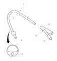
주지된 바와 같이, 카테타는 플렉서블 (Flexible)한 튜브로 정맥이나 요도 및 흉부 등에 삽입하는 관이다.As is well known, a catheter is a tube that is inserted into a vein, a urethra, a chest, etc. by a flexible tube.
이때, 도 1에 도시된 바와 같이, 신체 내부로 삽입되는 카테타의 경우는 수술 중 또는 수술 후에 환자의 환부 혈종이나 이물질, 체액 등 배출 대상 물질을 외부로 배출하기 위한 체액 배출 경로 (6)와 풍선을 부풀리기 위해서 물을 넣는 주입 경로 (8)가 단면에 각각 구성된 관체(4)로 이루어진다.1, in the case of a catheter inserted into the body, a body
또한, 카테타 (2)는 상기 관체(4) 후단에 상기 체액 배출경로(6)와 연통되어 이송된 채액을 외부로 배출하기 위한 배출단 (12)와 물 주입 경로 (8)와 연통되는 물 주입단(14)이 구비된 Y자 분기부(10)가 구성된다.The
이러한 카테타(2)는 상기 Y자 분기부(10)를 제조하기 위해서는 미리 제작된 관체에 두개의 핀을 꼽고서 금형에 넣고 닫은 다음에 실리콘을 주입하고 열로 성형해서 상기 Y자 분기부(10)가 관체(4)에 결합되도록 한다.In order to manufacture the Y-
하지만, 이러한 카테타(2)의 제조 장치는 Y자 성형 후에 핀을 다시 빼는 과정이 제품이 뜨거운 상태에서 수작업으로 이루어지다 보니 생산성이 떨어지며, 불량률이 높다는 문제가 있었다.However, in the apparatus for manufacturing such a
본 발명은 상기한 종래 기술의 사정을 감안하여 이루어진 것으로, 상부 금형 및 하부 금형과 직선핀과 사선핀을 전단에 형성한 지지대 몸체들이 스케쥴에 설정된 시간 간격 및 설정 궤적으로 위치되고 작업자가 미리 제작된 관체를 직선핀의 선단에 꽂으면 금형이 폐쇄되면서 자동으로 실리콘 액 주입 및 카테타의 이탈이 이루어지게 되므로 최소의 불량률로 최단 시간내에 카테타를 자동으로 제조할 수 있는 카테타 제조장치를 제공함에 그 목적이 있다.SUMMARY OF THE INVENTION The present invention has been made in view of the circumstances of the prior art described above, and it is an object of the present invention to provide an apparatus and a method for mounting the upper mold, lower mold, straight pins, When the tubular body is inserted into the tip of the straight pin, the injection of the silicone fluid and the disconnection of the catheter are automatically performed while the mold is closed, so that the catheter can be automatically manufactured in the shortest time with the minimum defect rate. have.
상기한 목적을 달성하기 위해, 본 발명의 바람직한 실시예에 따르면 그 상면에 관체가 들어가는 구멍(72)이 형성되고, 이동수단에 의해 승강되는 상부 금형(70)과; 그 하면에 관체가 들어가는 구멍(24)이 형성된 하부 금형(22)과; 그 전면에 일정간격으로 진입하는 사선핀(42)과 제 1가이드로드(48)가 형성되고, 일정간격으로 직선핀(52)이 관통하는 직선핀 관통공(43)이 형성되며, 이동수단에 의해 승강되는 제 1이동몸체(40)와; 상기 제 1이동몸체(40)의 후단에 밀착되어 구성되며, 그 전면에 일정간격으로 관체로 진입하는 상기 직선핀(52)이 형성되고, 이동수단에 의해 전진 및 후퇴하는 제 2이동몸체(50)와; 상기 제 1이동몸체(40)의 전방에 밀착되게 구성되며, 상기 사선핀(42)이 통과하는 사선핀 관통공(32)과 직선핀 관통공(30)이 일정간격으로 형성되고, 형성된 Y자 분기부(10)의 물 주입단(14)을 이탈시키기 위해 이동수단의 구동으로 전방으로 전진하는 제 2 지지대(26)와; 상기 제 2지지대(26)의 전방에 위치되며, 상기 제 2이동몸체(50)의 후퇴시 형성된 Y자 분기부(10)를 잡아주는 제 1지지대(60)로 구성된 것을 특징으로 하는 카테타 제조장치가 제공된다.In order to achieve the above object, according to a preferred embodiment of the present invention, an upper mold (70) having a hole (72) for receiving a tubular body on an upper surface thereof and being lifted and lowered by a moving means; A
바람직하게, 상기 제 2지지대(26)는 그 몸체 좌우측에 각각 상기 제 1가이드로드(48)가 통과하는 제 1가이드공(28)이 형성된 것을 특징으로 하는 카테타 제조장치가 제공된다.Preferably, the second support table 26 is provided with a
바람직하게, 상기 이동수단은 랙과 피니언인 것을 특징으로 하는 카테타 제조장치가 제공된다.Preferably, the moving means is a rack and a pinion.
바람직하게, 상기 제 1이동몸체(40)는 그 양단에 각각 제 2 가이드공(44)이 형성되고, 다이에 형성된 제 2 가이드로드(46)에 결합되어 승강되는 구조인 것을 특징으로 하는 카테타 제조장치가 제공된다.Preferably, the first moving
바람직하게, 상기 제 1이동몸체(40)의 좌우측 후방에는 제 3가이드로드(49)가 형성되고, 상기 제 2이동몸체(50)는 그 좌우측 몸체에 각각 상기 제 3가이드로드(49)와 관통하여 가이드하는 제 3가이드공(54)이 형성된 것을 특징으로 하는 카테타 제조장치가 제공된다.A
바람직하게, 상기 제 2지지대(26)는 상기 사선핀 관통공(32)이 형성된 부위가 경사면(34)으로 형성된 것을 특징으로 하는 카테타 제조장치가 제공된다.Preferably, the
바람직하게, 상기 제 1지지대(60)는 그 하부에 일정간격으로 상기 직선핀(52)의 후퇴시 Y자 분기부(10)의 배출단(12)이 직선핀(52)으로부터 이탈되게 잡아주는 U자 형상의 직선핀 걸림공(62)이 형성된 것을 특징으로 하는 카테타 제조장치가 제공된다.Preferably, the
본 발명에 따른 카테타 제조장치는 카테타를 구성하는 Y자 분기부를 별도의 금형에서 제조하고 금형으로부터 수동으로 이탈시키고 수동으로 이동시켜서 다시 관체를 결합시키는 종래의 장치와는 다르게, Y자 분기부의 제조와 관체 결합이 원스탑으로 이루어지고 자동으로 제조된 카테타가 금형으로부터 이탈되게 됨으로써 불량률이 감소되고 획기적으로 개선된 수율을 갖는 장점이 있다.The catheter manufacturing apparatus according to the present invention is different from the conventional apparatus in which the Y-shaped branching portion constituting the catheter is manufactured in a separate mold and is manually disengaged from the mold and manually moved to join the tubular body again. The tubular coupling is made with one-stop and the automatically manufactured catheter is detached from the mold, so that the defective rate is reduced and the yield is remarkably improved.
도 1은 종래의 실시예에 따른 카테타의 구성을 도시한 사시도,
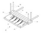
도2는 본 발명의 일실시예에 따른 카테타 제조장치의 각 구성이 모두 결합되어 실리콘을 주입하는 상태를 도시한 도면,
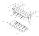
도3은 본 발명의 일실시예에 따른 카테타 제조장치의 각 구성이 결합된 상태에서 상부 금형만 상방으로 이탈된 상태를 도시한 도면,
도4는 도3의 제조장치중 제2지지대 및 제1,2이동몸체가 상방으로 이동된 상태를 도시한 도면,
도5는 도4의 카테타 제조장치중 제1지지대가 결합된 상태를 도시한 도면,
도6은 도5의 카테타 제조장치중 제1지지대가 분리되고 제2이동몸체가 후단으로 후퇴한 상태를 도시한 도면,
도7은 도6의 카테타 제조장치중 제2지지대가 전방으로 전진한 상태를 도시한 도면,
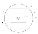
도8은 본 발명의 일실시예에 따른 카테타 제조장치가 복수개 구성된 작업다이를 도시한 평면도이다.1 is a perspective view showing a configuration of a catheter according to a conventional example,
FIG. 2 is a view illustrating a state in which silicon is injected into the catheter manufacturing apparatus according to an embodiment of the present invention,
FIG. 3 is a view illustrating a state in which only the upper mold is separated upward in a state where the respective components of the catheter manufacturing apparatus according to the embodiment of the present invention are combined,
FIG. 4 is a view showing a state in which the second support and the first and second moving bodies of the manufacturing apparatus of FIG. 3 are moved upward;
FIG. 5 is a view showing a state in which a first support of the catheter manufacturing apparatus of FIG. 4 is engaged;
6 is a view showing a state in which a first support is separated from the catheter manufacturing apparatus of FIG. 5 and the second moving body is retracted to the rear end,
FIG. 7 is a view showing a state in which the second support of the catheter manufacturing apparatus of FIG. 6 advances forward; FIG.
FIG. 8 is a plan view showing a working die having a plurality of catheter manufacturing apparatuses according to an embodiment of the present invention. FIG.
이하, 본 발명에 대해 도면을 참조하여 상세하게 설명한다.Hereinafter, the present invention will be described in detail with reference to the drawings.
도2는 본 발명의 일실시예에 따른 카테타 제조장치의 각 구성이 모두 결합되어 실리콘을 주입하는 상태를 도시한 도면, 도3은 본 발명의 일실시예에 따른 카테타 제조장치의 각 구성이 결합된 상태에서 상부 금형만 상방으로 이탈된 상태를 도시한 도면, 도4는 도3의 제조장치중 제2지지대 및 제1,2이동몸체가 상방으로 이동된 상태를 도시한 도면, 도5는 도4의 카테타 제조장치중 제1지지대가 결합된 상태를 도시한 도면, 도6은 도5의 카테타 제조장치중 제1지지대가 분리되고 제2이동몸체가 후단으로 후퇴한 상태를 도시한 도면, 도7은 도6의 카테타 제조장치중 제2지지대가 전방으로 전진한 상태를 도시한 도면, 도8은 본 발명의 일실시예에 따른 카테타 제조장치가 복수개 구성된 작업다이를 도시한 평면도이다.FIG. 2 is a view illustrating a state in which all the configurations of the catheter manufacturing apparatus according to the embodiment of the present invention are combined and injected with silicon. FIG. 3 is a cross-sectional view of the catheter manufacturing apparatus according to the embodiment of the present invention. FIG. 4 is a view showing a state in which the second support member and the first and second movable bodies are moved upward in the manufacturing apparatus of FIG. 3, and FIG. 5 is a view Fig. 6 is a view showing a state in which a first support is separated from a catheter manufacturing apparatus of Fig. 5 and the second moving body is retracted to the rear end, Fig. 6 FIG. 8 is a plan view showing a plurality of catheter manufacturing apparatuses according to an embodiment of the present invention. FIG. 8 is a plan view showing a working die having a plurality of catheter manufacturing apparatuses according to an embodiment of the present invention.
이를 참조하면, 본 발명의 일실시예에 따른 카테타 제조장치(20)는 상부 금형 및 하부 금형과 직선핀과 사선핀을 전단에 형성한 지지대 몸체들이 스케쥴에 설정된 시간 간격 및 설정 궤적으로 위치되고 작업자가 미리 제작된 관체를 직선핀의 선단에 꽂으면 금형이 폐쇄되면서 자동으로 실리콘 액 주입 및 카테타의 이탈이 이루어지게 되므로 최소의 불량률로 최단 시간내에 카테타를 자동으로 제조할 수 있는 장치이다.The
보다 상세하게, 본 발명의 일실시예에 따른 카테타 제조장치(20)는 미리 제작된 관체를 직선핀(52)와 사선핀(42)에 맞도록 끼운 상태에서 이동 수단에 의해 승강되는 상부 금형(70)과 하부 금형(22)이 밀착되게 각각 마주보고 위치되게 구성시킨 후 실리콘 액을 주입하고 열경화 시킨 후 상부 금형(70)을 분리시키고 상기 직선핀(52)과 사선핀(42)을 제거하면 본 발명을 통해 제조하고자 하는 카테타(2)를 제조할 수 있다.In more detail, the catheter manufacturing
또한, 본 발명의 일실시예에 따른 카테타 제조장치(20)는 그 전면에 일정간격으로 진입하는 사선핀(42)과 제 1가이드로드(48)가 형성되고, 일정간격으로 직선핀(52)이 관통하는 직선핀 관통공(43)이 형성되며, 이동수단에 의해 승강되는 제 1이동몸체(40)를 포함하여 구성된다.In the catheter manufacturing
이때, 상기 제 1이동몸체(40)는 그 양단에 각각 제 2 가이드공(44)이 형성되고, 다이(도 8참조, 80)에 형성된 제 2 가이드로드(46)에 결합되어 승강되는 구조이다.At this time, the first
또, 상기 제 1이동몸체(40)의 좌우측 후방에는 제 3가이드로드(49)가 형성되고, 상기 제 2이동몸체(50)는 그 좌우측 몸체에 각각 상기 제 3가이드로드(49)와 관통하여 가이드하는 제 3가이드공(54)이 형성되어져 있다.A
한편, 본 발명의 일실시예에 따른 카테타 제조장치(20)는 상기 제 1이동몸체(40)의 후단에 밀착되어 구성되며, 그 전면에 일정간격으로 상기 구멍(24,72)으로 진입하는 상기 직선핀(52)이 형성되고, 이동수단에 의해 전진 및 후퇴하는 제 2이동몸체(50)와; 상기 제 1이동몸체(40)의 전방에 밀착되게 구성되며,상기 사선핀(42)이 통과하는 사선핀 관통공(32)과 직선핀 관통공(30)이 일정간격으로 형성되고, 형성된 Y자 분기부(10)의 물 주입단(14)을 이탈시키기 위해 이동수단의 구동으로 전방으로 전진하는 제 2 지지대(26)와; 상기 제2지지대(26)의 전방에 위치되며, 상기 제 2이동몸체(50)의 후퇴로 인해 Y자 분기부(10)의 배출단(12)이 직선핀(52)으로부터 이탈되도록 Y자 분기부(10)를 잡아주는 제 1지지대(60)를 포함하여 구성된다.Meanwhile, the catheter manufacturing
또, 상기 제 2지지대(26)는 그 몸체 좌우측에 각각 상기 제 1가이드로드(48)가 통과하는 제 1가이드공(28)이 형성된다.In addition, the
이때, 상기 제 1이동몸체(40)의 승강시 상기 제 2지지대(26) 및 상기 제 2이동몸체(50)는 그 제 1이동몸체(40)의 승강과 일체로 승강될 수 있게 상기 제 1이동몸체(40)에 결합된다. 즉, 상기 제 2 지지대(26)는 상기 제 1가이드로드(48)를 통해 상기 제 1이동몸체(40)에 결합되어져 있으며, 상기 제 2이동몸체(50)는 상기 제 3가이드로드(49)를 통해 상기 제 1이동몸체(40)에 결합되어져 있다.At this time, when the first
따라서, 상기 제 1이동몸체(40)의 승강시 상기 제 2지지대(26) 및 상기 제 2이동몸체(50)는 그 제 1이동몸체(40)와 일체로 승강된다. 한편, 상기 이동수단은 랙과 피니언인 것이 바람직하며, 유압 실린더나 솔레노이드와 같은 이동수단을 본 발명에 적용하는 것도 충분히 가능하다.Therefore, when the first
또, 상기 제 2지지대(26)는 상기 사선핀 관통공(32)이 형성된 부위가 경사면(34)으로 형성되어져 상기 제 2지지대(26)가 전방으로 이동될 때 Y자 분기부(10)의 물 주입단(14)이 보다 원활하게 이탈될 수 있게 된다.The
또한, 상기 제 1지지대(60)는 그 하부에 일정간격으로 상기 직선핀(52)의 후퇴시 Y자 분기부(10)의 배출단(12)이 직선핀(52)으로부터 이탈되게 잡아주는 U자형상의 걸림공(62)이 형성되어져 있다.The
이하, 상기한 구성으로 이루어진 본 발명의 일실시예에 따른 카테타 제조장치(20)의 작동상태를 살펴본다.Hereinafter, an operation state of the
먼저, 도 4에 도시된 바와 같이 상기 제 2지지대(26)와 제 1이동몸체(40) 및 제 2이동몸체(50)가 결합된 상태에서, 작업자는 카테타(2)의 전단을 구성하는 상기 관체(4)를 상기 사선핀(42)과 직선핀(52)에 맞춰서 깊숙이 삽입한다.4, in a state where the second support frame 26, the first moving
삽입 길이는 상기 사선핀(42)과 직선핀(52)이 만나는 지점까지 상기 관체(4)를 삽입한다.The insertion length is such that the
그 상태에서, 도 3에 도시된 바와 같이 상기 제2지지대(26)와 제1이동몸체(40) 및 제2이동몸체(50)은 결합된 상태로 이동수단에 의해 하강한다. 그리고 도2에 도시된 바와 같이 상기 상부 금형(70)이 이동수단의 작동에 의해 하부 금형(22)의 상면에 밀착되게 하강하여 그 하부 금형(22)에 밀착된다.In this state, as shown in Fig. 3, the
그러면, 상부 금형(70)과 하부 금형(22) 사이에는 Y자 분기부 성형을 위한 공간이 생성되며, 그 공간으로 별도의 주입 노즐(미도시)을 통해서 실리콘 액의 주입이 이루어진다.Then, a space is formed between the
실리콘 액의 주입 후 열성형이 완료되면, 스케쥴링된 바와 같이 제어부(미도시)는 공지의 이동수단을 구동시켜 상기 상부 금형(70)을 도 3에 도시된 바와 같이, 상방으로 상승시킨다. 그러면, 상기 직선핀(52)과 사선핀(42)에 형성된 상기 Y자 분기부(10)가 끼워져있고 그 Y자 분기부(10)에 관체(4)가 일체로 형성된 상태의 카테타(2)가 노출된다.When thermoforming is completed after the injection of the silicon liquid, the control unit (not shown) drives the known moving means as shown in FIG. 3 to raise the
그리고, 공지의 이동수단이 구동되어 상기 제 1이동몸체(40)에 상승 구동력이 가해지면, 상기 제 1이동몸체(40)는 도 4에 도시된 바와 같이 상기 제 2가이드로드(46)를 통해 상방으로 가이드되면서 상승한다.When a known moving means is driven to apply a lift driving force to the first moving
이때, 상기 제 2지지대(26)와 제 1이동몸체(40) 및 제 2이동몸체(50)도 상기 제 1이동몸체(40)와 일체로 상승하고, 상기 카테타(2)는 상기 직선핀(52)과 사선핀(42)에 끼워진 상태로 상승한다.At this time, the
그리고, 도 5에 도시된 바와 같이 상기 제 1지지대(60)가 상기 Y자 분기부(10)의 상부에 밀착되도록 한다.As shown in FIG. 5, the
그 상태에서, 도 6에 도시된 바와 같이 상기 제 2이동몸체(50)에 구비된 이동수단(미도시)에 구동력을 가해지면 상기 제 2이동몸체(50)는 후방으로 후퇴되게 된다.In this state, when the driving force is applied to the moving means (not shown) provided on the second moving
그러면, 상기 제 1지지대(60)에 의해 상기 직선핀(52)이 후퇴시 상기 Y자 분기부(10)가 빠지지 않도록 잡아주게 된다.Then, when the linear pin (52) is retracted by the first support (60), the Y-shaped branch portion (10) is held so as not to come off.
그 상태에서, 도 7에 도시된 바와 같이, 상기 제 1 지지대(60)는 제거하고, 상기 제 2 지지대(26)가 전방으로 이동하면 상기 제 2지지대(26)가 Y자 분기부(10)를 밀어내면서 낙하시킨다.7, the
그로인해, Y자 분기부(10)와 관체(4)가 결합된 카테타(2)가 제조된다.Thereby, the
도 8은 본 발명의 일실시예에 따른 카테타 제조장치가 복수개 구성된 작업다이를 도시한 평면도이다.FIG. 8 is a plan view showing a working die having a plurality of catheter manufacturing apparatuses according to an embodiment of the present invention. FIG.
이를 참조하면, 본 발명의 일실시예에 따른 카테타 제조장치(20)는 작업자가 상기 관체(4)를 상기 사선핀(42)과 상기 직선핀(52)에 맞게 꽂아주는 작업은 수작업으로 수행해야만 한다.In the
따라서, 본 발명의 일실시예에 따른 카테타 제조장치(20)는 단일의 작업자가 작업할 수 있는 장치 안착 다이(80)의 상면에 복수개가 형성되어져 있으면서, 상기 장치 안착다이(80)는 중앙에 형성된 회전축(82)이 180도의 회전을 반복함으로써 빠른 시간동안 상기 관체(4)를 상기 사선핀(42)과 상기 직선핀(52)의 전단에 꽂아넣는 작업을 수행할 수 있게 된다.Therefore, in the
한편, 본 발명의 실시예에 따른 카테타 제조장치는 단지 상기한 실시예에 한정되는 것이 아니라 그 기술적 요지를 이탈하지 않는 범위내에서 다양한 변경이 가능하다.Meanwhile, the catheter manufacturing apparatus according to the embodiment of the present invention is not limited to the above-described embodiment, but various modifications are possible within the scope of the present invention.
2:카테타, 4:관체,
10:Y자 분기부, 12:배출단,
14:물주입단, 20:카테타 제조장치,
22:하부금형, 26:제 2지지대,
40:제 1이동몸체, 50:제 2이동몸체,
60:제 1지지대, 70:상부금형.2: catheter, 4: tubular body,
10: Y-minute base, 12: Outlet,
14: Filling of water, 20: Catheter manufacturing device,
22: lower mold, 26: second support,
40: first moving body, 50: second moving body,
60: first support, 70: upper mold.
Claims (7)
Translated fromKorean하면에 관체가 들어가는 구멍(24)이 형성된 하부 금형(22)과;
전면에 일정간격으로 진입하는 사선핀(42)과 제 1가이드로드(48)가 형성되고, 일정간격으로 직선핀(52)이 관통하는 직선핀 관통공(43)이 형성되며, 이동수단에 의해 승강되는 제 1이동몸체(40)와;
상기 제 1이동몸체(40)의 후단에 밀착되어 구성되며, 그 전면에 일정간격으로 관체로 진입하는 상기 직선핀(52)이 형성되고, 이동수단에 의해 전진 및 후퇴하는 제 2이동몸체(50)와;
상기 제 1이동몸체(40)의 전방에 밀착되게 구성되며, 상기 사선핀(42)이 통과하는 사선핀 관통공(32)과 직선핀 관통공(30)이 일정간격으로 형성되고, 형성된 Y자 분기부(10)의 물 주입단(14)을 이탈시키기 위해 이동수단의 구동으로 전방으로 전진하는 제 2 지지대(26)와;
상기 제 2지지대(26)의 전방에 위치되며, 상기 제 2이동몸체(50)의 후퇴시 형성된 Y자 분기부(10)를 잡아주는 제 1지지대(60)로 구성된 것을 특징으로 하는 카테타 제조장치.An upper mold 70 having a hole 72 for receiving a tube body on an upper surface thereof and being lifted and lowered by a moving means;
A lower mold 22 having a hole 24 into which a tubular body is inserted;
A straight pin through hole 43 through which the straight pin 52 passes is formed at a predetermined interval, and the slanted line 42 and the first guide rod 48 are formed by the moving means A first moving body (40) to be lifted;
A second moving body 50 (50) which is formed in close contact with the rear end of the first moving body (40) and in which the straight fin (52) entering the tube at regular intervals is formed and which is moved forward and backward by the moving means )Wow;
And a linear fin through hole 30 through which the slanted line 42 passes and a linear fin through hole 30 are formed at predetermined intervals, A second support (26) which advances forward by driving of the moving means to release the water injection end (14) of the branch portion (10);
And a first support part (60) positioned in front of the second support part (26) and holding a Y - shaped branch part (10) formed at the time of retreating the second movable body (50) .
상기 제 2지지대(26)는 그 몸체 좌우측에 각각 상기 제 1가이드로드(48)가 통과하는 제 1가이드공(28)이 형성된 것을 특징으로 하는 카테타 제조장치.The method according to claim 1,
Wherein the second support base (26) has a first guide hole (28) through which the first guide rod (48) passes, respectively, on the right and left sides of the body.
상기 이동수단은 랙과 피니언인 것을 특징으로 하는 카테타 제조장치.The method according to claim 1,
Wherein the moving means is a rack and a pinion.
상기 제 1이동몸체(40)는 그 양단에 각각 제 2 가이드공(44)이 형성되고, 다이에 형성된 제 2 가이드로드(46)에 결합되어 승강되는 구조인 것을 특징으로 하는 카테타 제조장치.The method according to claim 1,
Wherein the first moving body (40) has a structure in which a second guide hole (44) is formed at both ends thereof, and is coupled to a second guide rod (46) formed on the die and elevated and lowered.
상기 제 1이동몸체(40)의 좌우측 후방에는 제 3가이드로드(49)가 형성되고, 상기 제 2이동몸체(50)는 그 좌우측 몸체에 각각 상기 제 3가이드로드(49)와 관통하여 가이드하는 제 3가이드공(54)이 형성된 것을 특징으로 하는 카테타 제조장치.The method according to claim 1,
A third guide rod 49 is formed on the left and right rear sides of the first movable body 40 and the second movable body 50 guides the left and right bodies through the third guide rod 49, And a third guide hole (54) is formed.
상기 제 2지지대(26)는 상기 사선핀 관통공(32)이 형성된 부위가 경사면(34)으로 형성된 것을 특징으로 하는 카테타 제조장치.The method according to claim 1,
Wherein the second support base (26) is formed with an inclined surface (34) at a portion where the oblique fin through hole (32) is formed.
상기 제 1지지대(60)는 그 하부에 일정간격으로 상기 직선핀(52)의 후퇴시 Y자 분기부(10)의 배출단(12)을 잡아주는 U자 형상의 직선핀 걸림공(62)이 형성된 것을 특징으로 하는 카테타 제조장치.The method according to claim 1,
The first support base 60 has a U-shaped straight fin-receiving hole 62 for holding the discharge end 12 of the Y-shaped branch 10 at a predetermined interval at the lower portion thereof when the linear pin 52 is retracted. Is formed in the catheter body.
Priority Applications (1)
| Application Number | Priority Date | Filing Date | Title |
|---|---|---|---|
| KR1020150053699AKR101653103B1 (en) | 2015-04-16 | 2015-04-16 | Catheter manufacturing apparatus |
Applications Claiming Priority (1)
| Application Number | Priority Date | Filing Date | Title |
|---|---|---|---|
| KR1020150053699AKR101653103B1 (en) | 2015-04-16 | 2015-04-16 | Catheter manufacturing apparatus |
Publications (1)
| Publication Number | Publication Date |
|---|---|
| KR101653103B1true KR101653103B1 (en) | 2016-09-01 |
Family
ID=56942720
Family Applications (1)
| Application Number | Title | Priority Date | Filing Date |
|---|---|---|---|
| KR1020150053699AActiveKR101653103B1 (en) | 2015-04-16 | 2015-04-16 | Catheter manufacturing apparatus |
Country Status (1)
| Country | Link |
|---|---|
| KR (1) | KR101653103B1 (en) |
Cited By (1)
| Publication number | Priority date | Publication date | Assignee | Title |
|---|---|---|---|---|
| KR102078553B1 (en)* | 2019-05-29 | 2020-03-02 | 최수봉 | Bonding system of connector and insulin tube |
Citations (4)
| Publication number | Priority date | Publication date | Assignee | Title |
|---|---|---|---|---|
| JP2005507288A (en)* | 2001-10-31 | 2005-03-17 | オメガ、クリティカル、ケア、リミテッド | Catheter manufacturing method, insert used in the method, and catheter manufactured by the method |
| JP2006263247A (en)* | 2005-03-25 | 2006-10-05 | Sumitomo Bakelite Co Ltd | Medical catheter, metal mold, and manufacturing method for medical catheter |
| KR101268302B1 (en)* | 2011-08-26 | 2013-05-28 | 손정남 | mold core installing method of hose production connecting distributor |
| JP2014525333A (en)* | 2011-09-06 | 2014-09-29 | エー.フォア.エル. エンドバスキュラー リサーチズ エス.アー. | Microcatheter |
- 2015
- 2015-04-16KRKR1020150053699Apatent/KR101653103B1/enactiveActive
Patent Citations (4)
| Publication number | Priority date | Publication date | Assignee | Title |
|---|---|---|---|---|
| JP2005507288A (en)* | 2001-10-31 | 2005-03-17 | オメガ、クリティカル、ケア、リミテッド | Catheter manufacturing method, insert used in the method, and catheter manufactured by the method |
| JP2006263247A (en)* | 2005-03-25 | 2006-10-05 | Sumitomo Bakelite Co Ltd | Medical catheter, metal mold, and manufacturing method for medical catheter |
| KR101268302B1 (en)* | 2011-08-26 | 2013-05-28 | 손정남 | mold core installing method of hose production connecting distributor |
| JP2014525333A (en)* | 2011-09-06 | 2014-09-29 | エー.フォア.エル. エンドバスキュラー リサーチズ エス.アー. | Microcatheter |
Cited By (1)
| Publication number | Priority date | Publication date | Assignee | Title |
|---|---|---|---|---|
| KR102078553B1 (en)* | 2019-05-29 | 2020-03-02 | 최수봉 | Bonding system of connector and insulin tube |
Similar Documents
| Publication | Publication Date | Title |
|---|---|---|
| WO2018232590A1 (en) | Injection molding die for tubular product and molding method thereof | |
| CN215684590U (en) | Novel tea making small tea cake equipment | |
| KR101653103B1 (en) | Catheter manufacturing apparatus | |
| KR20170119106A (en) | Catheter manufacturing apparatus | |
| CN109333939A (en) | A kind of double-slider extracting core mechanism | |
| CN109531916B (en) | Automatic material pulling device in injection molding machine | |
| CN116394467B (en) | A plastic mold processing and forming device | |
| CN112277243A (en) | Forming die for producing connector with insert | |
| JP2017087702A (en) | Apparatus for molding wire protection member with mold portion | |
| CN116198087A (en) | Plastic injection mold capable of self-demolding | |
| CN212498764U (en) | An injection mold for automobile row buttons | |
| CN210969792U (en) | Injection mold with profile modeling ejection mechanism | |
| CN209832437U (en) | Electric vehicle front wall panel mold with straight top and inclined top combined demolding mechanism | |
| CN223369934U (en) | Injection mold for inverted drilling button | |
| CN214687732U (en) | Injection mold with bent nozzle head | |
| JP2009039908A (en) | Injection molding apparatus | |
| CN214982969U (en) | An injection molding device that precisely introduces the mold core | |
| CN115592896B (en) | A mold and a demoulding method of the mold | |
| CN211807515U (en) | Mould convenient for opening mould | |
| CN214872290U (en) | Disposable medical puncture outfit die | |
| CN113080471B (en) | Get juice device fast | |
| CN205326156U (en) | Vertical spacing pulling mechanism of injection mold thimble board | |
| CN215472748U (en) | Product traceless ejection injection mold | |
| CN218050270U (en) | Pump barrel casting mould for pump assembly | |
| CN112936791B (en) | Injection molding mold for infusion set dosing injection parts |
Legal Events
| Date | Code | Title | Description |
|---|---|---|---|
| PA0109 | Patent application | St.27 status event code:A-0-1-A10-A12-nap-PA0109 | |
| PA0201 | Request for examination | St.27 status event code:A-1-2-D10-D11-exm-PA0201 | |
| D13-X000 | Search requested | St.27 status event code:A-1-2-D10-D13-srh-X000 | |
| P11-X000 | Amendment of application requested | St.27 status event code:A-2-2-P10-P11-nap-X000 | |
| P13-X000 | Application amended | St.27 status event code:A-2-2-P10-P13-nap-X000 | |
| R18-X000 | Changes to party contact information recorded | St.27 status event code:A-3-3-R10-R18-oth-X000 | |
| D14-X000 | Search report completed | St.27 status event code:A-1-2-D10-D14-srh-X000 | |
| PE0902 | Notice of grounds for rejection | St.27 status event code:A-1-2-D10-D21-exm-PE0902 | |
| P11-X000 | Amendment of application requested | St.27 status event code:A-2-2-P10-P11-nap-X000 | |
| P13-X000 | Application amended | St.27 status event code:A-2-2-P10-P13-nap-X000 | |
| E701 | Decision to grant or registration of patent right | ||
| PE0701 | Decision of registration | St.27 status event code:A-1-2-D10-D22-exm-PE0701 | |
| GRNT | Written decision to grant | ||
| PR0701 | Registration of establishment | St.27 status event code:A-2-4-F10-F11-exm-PR0701 | |
| PR1002 | Payment of registration fee | St.27 status event code:A-2-2-U10-U11-oth-PR1002 Fee payment year number:1 | |
| PG1601 | Publication of registration | St.27 status event code:A-4-4-Q10-Q13-nap-PG1601 | |
| P22-X000 | Classification modified | St.27 status event code:A-4-4-P10-P22-nap-X000 | |
| PR1001 | Payment of annual fee | St.27 status event code:A-4-4-U10-U11-oth-PR1001 Fee payment year number:4 | |
| PR1001 | Payment of annual fee | St.27 status event code:A-4-4-U10-U11-oth-PR1001 Fee payment year number:5 | |
| PR1001 | Payment of annual fee | St.27 status event code:A-4-4-U10-U11-oth-PR1001 Fee payment year number:6 | |
| PR1001 | Payment of annual fee | St.27 status event code:A-4-4-U10-U11-oth-PR1001 Fee payment year number:7 | |
| PR1001 | Payment of annual fee | St.27 status event code:A-4-4-U10-U11-oth-PR1001 Fee payment year number:8 | |
| PR1001 | Payment of annual fee | St.27 status event code:A-4-4-U10-U11-oth-PR1001 Fee payment year number:9 | |
| PR1001 | Payment of annual fee | St.27 status event code:A-4-4-U10-U11-oth-PR1001 Fee payment year number:10 |