KR101652401B1 - 3D image display apparatus and 3D image display method - Google Patents
3D image display apparatus and 3D image display methodDownload PDFInfo
- Publication number
- KR101652401B1 KR101652401B1KR1020100087668AKR20100087668AKR101652401B1KR 101652401 B1KR101652401 B1KR 101652401B1KR 1020100087668 AKR1020100087668 AKR 1020100087668AKR 20100087668 AKR20100087668 AKR 20100087668AKR 101652401 B1KR101652401 B1KR 101652401B1
- Authority
- KR
- South Korea
- Prior art keywords
- light
- shutter
- image
- pattern
- array
- Prior art date
- Legal status (The legal status is an assumption and is not a legal conclusion. Google has not performed a legal analysis and makes no representation as to the accuracy of the status listed.)
- Active
Links
Images


Classifications
- H—ELECTRICITY
- H04—ELECTRIC COMMUNICATION TECHNIQUE
- H04N—PICTORIAL COMMUNICATION, e.g. TELEVISION
- H04N13/00—Stereoscopic video systems; Multi-view video systems; Details thereof
- H04N13/30—Image reproducers
- H04N13/361—Reproducing mixed stereoscopic images; Reproducing mixed monoscopic and stereoscopic images, e.g. a stereoscopic image overlay window on a monoscopic image background
- H—ELECTRICITY
- H04—ELECTRIC COMMUNICATION TECHNIQUE
- H04N—PICTORIAL COMMUNICATION, e.g. TELEVISION
- H04N13/00—Stereoscopic video systems; Multi-view video systems; Details thereof
- H04N13/30—Image reproducers
- H04N13/302—Image reproducers for viewing without the aid of special glasses, i.e. using autostereoscopic displays
- H04N13/305—Image reproducers for viewing without the aid of special glasses, i.e. using autostereoscopic displays using lenticular lenses, e.g. arrangements of cylindrical lenses
- H—ELECTRICITY
- H04—ELECTRIC COMMUNICATION TECHNIQUE
- H04N—PICTORIAL COMMUNICATION, e.g. TELEVISION
- H04N13/00—Stereoscopic video systems; Multi-view video systems; Details thereof
- H04N13/30—Image reproducers
- H04N13/302—Image reproducers for viewing without the aid of special glasses, i.e. using autostereoscopic displays
- H04N13/31—Image reproducers for viewing without the aid of special glasses, i.e. using autostereoscopic displays using parallax barriers
- H—ELECTRICITY
- H04—ELECTRIC COMMUNICATION TECHNIQUE
- H04N—PICTORIAL COMMUNICATION, e.g. TELEVISION
- H04N13/00—Stereoscopic video systems; Multi-view video systems; Details thereof
- H04N13/30—Image reproducers
- H04N13/302—Image reproducers for viewing without the aid of special glasses, i.e. using autostereoscopic displays
- H04N13/32—Image reproducers for viewing without the aid of special glasses, i.e. using autostereoscopic displays using arrays of controllable light sources; using moving apertures or moving light sources
Landscapes
- Engineering & Computer Science (AREA)
- Multimedia (AREA)
- Signal Processing (AREA)
- Testing, Inspecting, Measuring Of Stereoscopic Televisions And Televisions (AREA)
Abstract
Translated fromKoreanDescription
Translated fromKorean하나의 화면에 2D 영상과 3D 영상을 선택적으로 표시할 수 있는 입체 영상 디스플레이 장치 및 입체 영상 표시 방법에 관한 것이다.To a stereoscopic image display device and a stereoscopic image display method capable of selectively displaying a 2D image and a 3D image on one screen.
3차원 영상은 사람의 두 눈을 통한 스테레오 시각의 원리에 의해 이루어지는데, 두 눈이 약 65mm 정도 떨어져서 존재하기 때문에 나타나는 양안시차(binocular parallax)가 입체감의 가장 중요한 요인이라고 할 수 있다. 3차원 영상 디스플레이에는 안경을 이용한 디스플레이와 무안경 방식의 디스플레이가 있으며, 무안경 방식의 디스플레이는 안경을 사용하지 않고 좌우 영상을 분리하여 3차원 영상을 얻는 것이다. 무안경 방식에는 예를 들어 패럴렉스 배리어 방식(parallax barrier)과 렌티큘러(lenticular) 방식이 있다.The three-dimensional image is made by the principle of stereoscopic vision through the two eyes of a person. Binocular parallax, which occurs because the eyes are separated by about 65mm, is the most important factor of the stereoscopic effect. In the three-dimensional image display, there is a display using glasses and a non-glasses type display. In the non-glasses type display, three-dimensional images are obtained by separating left and right images without using glasses. The non-eyeglass system includes, for example, a parallax barrier system and a lenticular system.
패럴렉스 배리어 방식은 좌우 양안이 각각 보아야 할 화상을 교대로 세로 무늬 모양으로 인쇄 또는 사진으로 인화하여 이것을 극히 가느다란 세로 격자열 즉, 배리어를 이용하여 보는 것이다. 이렇게 함으로써, 좌안에 들어올 세로 무늬 화상과 우안에 들어올 세로 무늬 화상이 배리어에 의해 배분되어 좌안과 우안으로 각각 다른 시점(view point)의 화상이 보임으로써 입체 영상으로 보이는 것이다.The parallax barriers method is to alternately print the images to be viewed in both the right and left eyes in a vertical pattern or print them using photographs, and to view them using an extremely thin vertical grid line, that is, a barrier. By doing so, the vertical pattern image to be entered into the left eye and the vertical pattern image to be entered into the right eye are distributed by the barrier, and the images of the different view points are seen by the left eye and the right eye, respectively.
렌티큘러 방식은 렌티큘러 렌즈의 초점면에 좌우안에 대응하는 화상을 배치하고, 상기 렌티큘러 렌즈를 통하여 관찰하면 렌즈의 지향 특성에 따라 좌안과 우안에 화상이 분리되어 입체 형상이 형성된다.In the lenticular method, images corresponding to left and right focal planes of a lenticular lens are arranged, and when viewed through the lenticular lens, an image is separated from the left eye and the right eye according to the directivity characteristic of the lens, and a three-dimensional shape is formed.
패럴렉스 배리어 방식이나 렌티큘러 방식은 베리어나 렌즈의 주기, 초점 거리, 방향 등이 고정되어 있어 입체 영상을 감상할 수 있는 영역이 고정되어 있다. 예를 들어, 렌티큘러 렌즈 또는 베리어의 배열 방향에 따라 영상을 볼 수 있는 방향이 정해져 있으므로 가로 보기 또는 세로 보기 중 한 가지 모드에서만 영상을 시청할 수 있다. 그런데, 입체 영상 장치의 발달로 영상의 시청 방향의 선택이나 2D나 3D의 선택 등 다양한 선택성을 가지는 것이 요구될 수 있다.In the parallax barrier system and the lenticular system, the period, the focal distance, and the direction of the barrier or the lens are fixed, and an area where the stereoscopic image can be viewed is fixed. For example, since the direction in which the image can be viewed is determined according to the arrangement direction of the lenticular lens or the barrier, the image can be viewed only in one of the horizontal view mode and the portrait view mode. However, development of a stereoscopic image device may require a variety of selectivity such as selection of the viewing direction of the image or selection of 2D or 3D.
한 화면에서 선택적으로 2D 영상과 3D 영상을 표시하는 입체 영상 디스플레이 장치를 제공한다.A stereoscopic image display device for displaying a 2D image and a 3D image selectively on one screen is provided.
광의 출광 방향을 조절하여 입체 영상을 표시하는 방법을 제공한다.A method for displaying a stereoscopic image by adjusting an outgoing direction of light is provided.
본 발명의 실시예에 따른 입체 영상 디스플레이 장치는, 3D 영상 영역과 2D 영상 영역을 생성하는 입력부; 상기 입력부에서 입력된 3D 영상 영역에 대응되는 마스크 패턴을 형성하는 마스크 패턴 형성부; 상기 마스크 패턴을 이용하여 제1눈을 위한 제1 셔터 패턴과 제2눈을 위한 제2 셔터 패턴을 형성하는 셔터 패턴 형성부; 복수 개의 셀과, 상기 복수 개의 셀 별로 광의 출광 방향을 조절할 수 있도록 된 출광 유닛을 가지는 백라이트 유닛; 상기 제1 셔터 패턴과 제2 셔터 패턴에 따라 상기 출광 유닛에서 광의 출광 방향을 조절하는 제어부; 및 상기 백라이트 유닛으로부터 출사된 광을 이용하여 영상을 형성하는 디스플레이 패널;을 포함할 수 있다.A stereoscopic image display apparatus according to an embodiment of the present invention includes an input unit for generating a 3D image region and a 2D image region; A mask pattern forming unit for forming a mask pattern corresponding to the 3D image region input from the input unit; A shutter pattern forming unit for forming a first shutter pattern for the first eye and a second shutter pattern for the second eye using the mask pattern; A backlight unit having a plurality of cells and an outgoing unit capable of adjusting an outgoing direction of light for each of the plurality of cells; A control unit for adjusting an outgoing direction of light in the light emission unit according to the first shutter pattern and the second shutter pattern; And a display panel that forms an image using light emitted from the backlight unit.
본 발명의 일 측면에 따르면, 상기 입력부는 3D 영상 영역의 좌표를 생성하는 좌표 생성부를 포함할 수 있다.According to an aspect of the present invention, the input unit may include a coordinate generator for generating coordinates of a 3D image area.
본 발명의 다른 측면에 따르면, 상기 출광 유닛은, 곡면에 2차원 어레이 형태로 배열되고, 곡면 형상을 가지는 복수 개의 반사부; 및 상기 반사부에 대응되게 마련되는 광원;을 포함할 수 있다.According to another aspect of the present invention, the outgoing unit includes: a plurality of reflective parts arranged in a two-dimensional array on a curved surface and having a curved shape; And a light source provided corresponding to the reflective portion.
본 발명의 다른 측면에 따르면, 상기 반사부는 상기 광원으로부터의 광을 콜리메이팅 광으로 반사시킬 수 있다.According to another aspect of the present invention, the reflector may reflect the light from the light source as collimating light.
본 발명의 다른 측면에 따르면, 상기 광원은 각각 독립적으로 제어될 수 있다.According to another aspect of the present invention, the light sources may be independently controlled.
본 발명의 다른 측면에 따르면, 상기 출광 유닛은, 광원; 상기 광원으로부터의 광을 가이드하는 도광판; 및 상기 도광판 위에 상기 셀 단위로 구획되고, 전기적 신호에 따라 굴절면의 기울기를 조절할 수 있는 프리즘 어레이;를 포함할 수 있다.According to another aspect of the present invention, the outgoing unit includes: a light source; A light guide plate for guiding light from the light source; And a prism array partitioned by the cell unit on the light guide plate and capable of adjusting the tilt of the refracting surface according to an electrical signal.
본 발명의 다른 측면에 따르면, 상기 도광판은 웨지형으로 형성될 수 있다.According to another aspect of the present invention, the light guide plate may be formed in a wedge shape.
본 발명의 다른 측면에 따르면, 상기 프리즘 어레이는 전기 습윤 소자를 포함할 수 있다.According to another aspect of the invention, the prism array may comprise an electrowetting element.
본 발명의 다른 측면에 따르면, 상기 프리즘 어레이는 2차원 어레이 구조를 가질 수 있다.According to another aspect of the present invention, the prism array may have a two-dimensional array structure.
본 발명의 다른 측면에 따르면, 상기 출광 유닛은, 광을 선택적으로 on-off 스위칭하는 광 어레이; 및 상기 광 어레이로부터 나온 광의 진행 방향을 한정하는 방향 조절부;를 포함할 수 있다.According to another aspect of the present invention, the outgoing unit includes: an optical array for selectively on-off switching light; And a direction adjusting unit that defines a traveling direction of light emitted from the optical array.
본 발명의 다른 측면에 따르면, 상기 출광 유닛은, 광원; 상기 광원으로부터의 광을 가이드하는 도광판; 상기 도광판 위에 셀 별로 구비된 것으로 각각 독립적으로 개폐되는 복수 개의 셔터를 가지는 셔터 어레이; 및 상기 셔터 어레이 위에 구비된 렌즈 어레이;를 포함할 수 있다.According to another aspect of the present invention, the outgoing unit includes: a light source; A light guide plate for guiding light from the light source; A shutter array having a plurality of shutters that are independently provided on a cell-by-cell basis on the light guide plate; And a lens array provided on the shutter array.
본 발명의 다른 측면에 따르면, 상기 셔터 어레이는 액정 셔터, 전기 습윤 셔터, 또는 FTIR(Frustrated Total Internal Reflection) 셔터를 포함할 수 있다.According to another aspect of the present invention, the shutter array may include a liquid crystal shutter, an electrowetting shutter, or a frustrated total internal reflection (FTIR) shutter.
본 발명의 다른 측면에 따르면, 상기 셔터 어레이는 2차원 구조로 배열될 수 있다.According to another aspect of the present invention, the shutter array may be arranged in a two-dimensional structure.
본 발명의 다른 측면에 따르면, 상기 셀의 이웃하는 셔터의 투과도를 조절하여 광의 출광 각도가 조절될 수 있다.According to another aspect of the present invention, an outgoing angle of light can be adjusted by controlling the transmittance of the neighboring shutter of the cell.
본 발명의 다른 측면에 따르면, 상기 셔터의 투과도는 편광에 의한 투과량 조절, 셔터의 단위 면적 당 투과가 일어나는 면적, 단위 시간 당 투과가 일어나는 시간 중 적어도 하나를 변화시켜 조절될 수 있다.According to another aspect of the present invention, the transmittance of the shutter can be adjusted by changing at least one of a transmittance adjustment by polarized light, an area where transmission per unit area of the shutter occurs, and a transmission time per unit time.
본 발명의 다른 측면에 따르면, 상기 출광 유닛은, 상기 셀 단위로 구비되고, 각각 독립적으로 on-off 조절되는 복수 개의 광원을 가지는 광원 어레이; 및 상기 각 셀에 대응되게 구비되어 상기 복수 개의 광원에서 출사된 광의 진행 방향을 한정하는 핀홀 어레이;를 포함할 수 있다.According to another aspect of the present invention, the light-emitting unit includes: a light source array having a plurality of light sources provided on a cell-by-cell basis and independently controlled on-off; And a pinhole array provided corresponding to each cell to define a traveling direction of light emitted from the plurality of light sources.
본 발명의 다른 측면에 따르면, 상기 제1 셔터 패턴은 2D 영상을 위한 패턴과 좌안 영상을 위한 패턴을 포함하고, 제2 셔터 패턴은 2D 영상을 위한 패턴과 우안 영상을 위한 패턴을 포함할 수 있다.According to another aspect of the present invention, the first shutter pattern includes a pattern for a 2D image and a pattern for a left eye image, and the second shutter pattern may include a pattern for a 2D image and a pattern for a right eye image .
본 발명의 일 실시예에 따른 입체 영상 표시 방법은, 2D 영상 영역과 3D 영상 영역을 입력하는 단계; 상기 3D 영상 영역에 대응되는 마스크 패턴을 형성하는 단계; 상기 마스크 패턴을 이용하여 제1눈을 위한 제1 셔터 패턴과 제2눈을 위한 제2 셔터 패턴을 형성하는 단계; 복수 개의 셀과, 상기 셀 별로 광의 출광 방향을 조절할 수 있도록 된 출광 유닛을 포함하는 백라이트 유닛의 상기 각 셀에서의 출광 방향을 상기 제1 셔터 패턴과 제2 셔터 패턴에 따라 조절하여 광을 출력하는 단계;를 포함할 수 있다.According to an embodiment of the present invention, there is provided a stereoscopic image display method comprising: inputting a 2D image area and a 3D image area; Forming a mask pattern corresponding to the 3D image area; Forming a first shutter pattern for the first eye and a second shutter pattern for the second eye using the mask pattern; The light output direction of each of the cells of the backlight unit including a plurality of cells and an outgoing unit capable of adjusting an outgoing direction of light for each cell is adjusted according to the first shutter pattern and the second shutter pattern to output light Step.
본 발명의 실시예에 따른 입체 영상 디스플레이 장치 및 방법은 한 화면에서 2D 영상과 3D 영상을 동시에 표시할 수 있어 예를 들어 윈도우 형태의 여러 화면에서 각각에 적합한 2D 영상과 3D 영상을 효과적으로 표시할 수 있다.The apparatus and method for displaying a stereoscopic image according to an exemplary embodiment of the present invention can simultaneously display a 2D image and a 3D image on one screen and can display a 2D image and a 3D image suitable for each screen on a window- have.
도 1은 본 발명의 일 실시예에 따른 입체 영상 디스플레이 장치의 개략적인 도면이다.
도 2는 도 1에 도시된 입체 영상 디스플레이 장치의 구성 블록도이다.
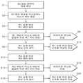
도 3은 본 발명의 일 실시예에 따른 입체 영상 표시 방법을 나타낸 블록도이다.
도 4a 및 도 4b는 본 발명의 일 실시예에 따른 입체 영상 표시 방법을 설명하기 위한 도면이다.
도 5와 도 6은 본 발명의 실시예에 따른 입체 영상 디스플레이 장치에 채용되는 백라이트 유닛의 동작 설명을 위한 도면이다.
도 7 내지 도 10은 본 발명의 실시예에 따른 입체 영상 디스플레이 장치에 채용되는 백라이트 유닛의 여러 가지 예들을 도시한 것이다.
도 11a 및 도 11b는 도 7에 도시된 백라이트 유닛을 이용하여 2D 영상과 3D 영상을 표시하는 예를 도시한 것이다.
도 12a 및 도 12b는 도 9에 도시된 백라이트 유닛을 이용하여 2D 영상과 3D 영상을 표시하는 에를 도시한 것이다.
도 13a 및 도 13b는 도 9에 도시된 백라이트 유닛에서 출광 각도를 조절하는 방법을 설명하기 위한 도면이다.
도 14는 도13a와 도 13b에 도시된 백라이트 유닛에서 출광되는 광의 출광 각도에 따른 광속을 도시한 것이다.
도 15는 서로 다른 출광 각도를 가지고 출광되는 광을 합성하여 광의 출광 각도를 조절하는 방법을 설명하기 위한 도면이다.1 is a schematic view of a stereoscopic image display apparatus according to an embodiment of the present invention.
2 is a block diagram of the stereoscopic image display apparatus shown in FIG.
3 is a block diagram illustrating a stereoscopic image display method according to an embodiment of the present invention.
4A and 4B are views for explaining a stereoscopic image display method according to an embodiment of the present invention.
5 and 6 are views for explaining the operation of the backlight unit employed in the stereoscopic image display apparatus according to the embodiment of the present invention.
7 to 10 illustrate various examples of the backlight unit employed in the stereoscopic image display apparatus according to the embodiment of the present invention.
11A and 11B illustrate an example of displaying a 2D image and a 3D image using the backlight unit shown in FIG.
12A and 12B are views showing a 2D image and a 3D image using the backlight unit shown in FIG.
13A and 13B are views for explaining a method of adjusting an outgoing angle in the backlight unit shown in FIG.
14 shows a light flux according to an outgoing angle of light emitted from the backlight unit shown in Figs. 13A and 13B.
FIG. 15 is a view for explaining a method of adjusting the outgoing angle of light by synthesizing the outgoing light with different outgoing angles.
이하, 본 발명의 실시예들에 따른 입체 영상 디스플레이 장치 및 입체 영상 표시 방법에 대해 첨부된 도면을 참조하여 상세히 설명한다. 도면에서 동일한 참조부호는 동일한 구성요소를 지칭하며, 각 구성요소의 크기나 두께는 설명의 편의를 위하여 과장되어 있을 수 있다.Hereinafter, a stereoscopic image display apparatus and a stereoscopic image display method according to embodiments of the present invention will be described in detail with reference to the accompanying drawings. In the drawings, the same reference numerals denote the same elements, and the sizes and thicknesses of the respective elements may be exaggerated for convenience of explanation.
본 발명의 실시예에 따른 입체 영상 디스플레이 장치(1)는 도 1을 참조하면, 하나의 화면에 2D 영상 영역(3)(5)과 3D 영상 영역(7)을 포함할 수 있다. 예를 들어, 컴퓨터 모니터에서 윈도우의 형태로 복수 개의 영역이 표시될 때, 복수 개의 영역 중 일부는 3D 영상 콘텐츠를 포함하고, 나머지는 2D 영상 콘텐츠를 포함할 수 있다. 3D 영상 콘텐츠는 예를 들어 영화를 포함하고, 2D 영상 콘텐츠는 문서를 포함할 수 있다. 여기서, 복수 개의 영역을 모두 2D 영상으로 표시하거나 3D 영상으로 표시하는 경우 해당 콘텐츠에 적합하지 않은 모드로 표시되어 사용에 불편함을 초래할 수 있다. 예를 들어, 스크린의 복수 개의 영역이 모두 3D로 표시될 때, 문자 또는 기호와 같은 2D 영상 콘텐츠의 가독성이 저하될 수 있다. 이와 반대로, 스크린의 복수 개의 영역이 모두 2D로 표시될 때, 3D 영상 콘텐츠의 깊이감이 표시되기 어렵다. 이런 경우, 본 발명의 실시예에 따른 입체 영상 디스플레이 장치는 하나의 화면에서 2D 영상 영역에서는 2D 영상을, 3D 영상 영역에서는 3D 영상을 표시할 수 있다.Referring to FIG. 1, a stereoscopic
도 2는 본 발명의 일 실시예에 따른 입체 영상 디스플레이 장치를 개략적으로 도시한 것으로, 3D 영상 영역과 2D 영상 영역을 생성하는 입력부(10)와, 상기 입력부(10)로부터 입력된 3D 영상 영역에 대응되는 마스크 패턴을 형성하는 마스크 패턴 형성부(12)와, 상기 마스크 패턴을 이용하여 제1 셔터 패턴과 제2 셔터 패턴을 형성하는 셔터 패턴 형성부(14)를 포함할 수 있다.FIG. 2 schematically shows a stereoscopic image display apparatus according to an embodiment of the present invention. The stereoscopic image display apparatus includes an
상기 입력부(10)는 예를 들어 3D 영상 영역의 좌표를 생성하는 좌표 생성부를 포함할 수 있다. 도 3을 참조하면, 상기 입력부(10)는 3D 영상 영역의 좌표를 생성하고(S1), 상기 마스크 패턴 형성부(12)는 상기 입력부(10)로부터 입력된 3D 영상 영역을 마스킹하는 마스크 패턴을 형성할 수 있다(S2). 마스크 패턴은 3D영상이 표현될 영역과 2D영상이 표현될 영역을 구분할 수 있다.The
상기 셔터 패턴 형성부(14)는 상기 마스크 패턴을 이용하여 3D영상영역에 제1눈, 예를 들어 좌안을 위한 제1 패턴을 형성할 수 있다(S3). 그리고, 상기 제1 패턴과 마스크 패턴을 결합하여 좌안을 위한 제1 셔터패턴을 만들고(S4), 이를 백라이트 유닛(Backlight Unit)에 전송할 수 있다. 이와 동시 또는 순차적으로 좌안에 들어갈 영상을 준비하여(S8) 패널(Panel)에 전송할 수 있다(S10). 제1눈을 위한 제1셔터 패턴을 형성한 것과 같은 방법으로, 제2눈을 위한 제2셔터 패턴을 형성할 수 있다. 셔터 패턴 형성부(14)가 제2눈, 예를 들어 우안을 위한 제2 패턴을 형성할 수 있다(S12). 그리고, 제2 패턴과 상기 마스크 패턴을 결합하여 우안을 위한 제2셔터 패턴을 형성할 수 있다. 이와 같은 프로세스들은 마스크 패턴을 형성하는 마스크 패턴 형성부(12)와 셔터 패턴을 형성하고, 마스크 패턴과 결합하는 셔터 패턴 형성부(14), 백라이트 유닛과 패널을 제어하는 제어부(16)에서 이루어질 수 있다. 도 3에 도시된 각 단계의 블록들은 H/W 또는 S/W로 구성 될 수 있다.The shutter pattern forming unit 14 may form a first pattern for the first eye, for example, the left eye, in the 3D image area using the mask pattern (S3). Then, the first pattern and the mask pattern are combined to create a first shutter pattern for the left eye (S4), and the first shutter pattern can be transmitted to the backlight unit. An image to be simultaneously or sequentially entered into the left eye can be prepared (S8) and transmitted to the panel (S10). The second shutter pattern for the second eye can be formed in the same manner as the first shutter pattern for the first eye is formed. The shutter pattern forming portion 14 can form a second pattern for the second eye, for example, the right eye (S12). A second shutter pattern for the right eye can be formed by combining the second pattern and the mask pattern. Such processes include a mask
도 4a와 도 4b는 좌안과 우안을 위한 패턴을 형성하는 과정을 보여준다. 상기 입력부(10)는 도 4a에 도시된 바와 같이 화면(30)에서 3D 영상 영역(33)의 좌표(X0,Y0)(X1,Y1)를 생성할 수 있다. 좌표를 생성하는 방법은 여러 가지가 있겠지만,예를 들어, 사각형의 3D 영상 영역의 대각선 방향으로 마주보는 두 점의 좌표를 생성할 수 있다. 그 다음, 상기 마스크 패턴 형성부(12)는 상기 3D 영상 영역(33)에 대응되는 마스크 패턴(35)을 형성할 수 있다. 그리고, 셔터 패턴 형성부(14)는 좌안으로 빛을 보내기 위한 제1패턴(40)을 형성할 수 있다. 상기 제1패턴(40)과 상기 마스크 패턴(35)을 결합하여 좌안용 제1셔터 패턴(50)을 형성할 수 있다. 상기 좌안용 셔터 패턴(50)은 3D 영상 영역의 좌안용 패턴(56)과 2D 영상 영역의 패턴(59)을 포함할 수 있다. 도 4b는 우안용 셔터패턴(52)을 형성하는 과정을 도시한 것으로, 예를 들어, 좌안용 제1 셔터 패턴을 형성시 만들었던 마스크 패턴(35)을 그대로 사용할 수 있다. 셔터 패턴 형성부(14)는 우안으로 빛을 보내기 위한 제2 패턴(42)을 상기 마스크 패턴(35)과 결합하여 우안용 제2 셔터 패턴(52)를 형성할 수 있다.4A and 4B show a process of forming a pattern for the left eye and the right eye. The
제어부(16)는 상기 제1셔터 패턴을 백라이트 유닛(17)에 전송하고(S6), 제1눈을 위한 영상 신호를 준비하여(S8), 제1눈을 위한 영상 신호를 디스플레이 패널(19)에 전송할 수 있다(S10). 상기 제어부(16)는 제2셔터 패턴을 백라이트 유닛(17)에 전송하고(S16), 제2눈을 위한 영상 신호를 준비하여(S18) 제2눈을 위한 영상 신호를 디스플레이 패널(19)에 전송할 수 있다(S20).The
상기 백라이트 유닛(17)은 광의 출광 방향을 조절하여 좌안 영상과 우안 영상의 시역을 분리함으로써 3D 영상을 표시할 수 있다. 도 5는 본 발명의 실시예에 따른 디스플레이 장치에 채용될 수 있는 백라이트 유닛(70)을 개략적으로 도시한 것이다. 상기 백라이트 유닛(70)은 복수 개의 셀(Z11...Zmn)을 포함하고, 상기 각 셀은 광의 출광 방향을 조절하는 출광 유닛(75)을 포함할 수 있다. 예를 들어 상기 셀은 2차원 구조로 배열될 수 있다. 디스플레이 패널(80)은 상기 백라이트 유닛(70)에서 조사된 광을 이용하여 영상을 표시할 수 있다. 상기 디스플레이 패널(80)은 복수 개의 화소를 포함하고, 각 화소별로 광의 투과율을 제어하여 영상을 형성할 수 있다. 상기 디스플레이 패널(80)은 예를 들어 LCD 패널일 수 있다.The
도 6을 참조하면, 상기 출광 유닛(75)은 각 셀별로 광의 출광 방향을 선택적으로 조절하여, 광을 좌안(LE)으로 보내거나 우안으로 보내거나 또는 좌안과 우안에 같이 보내는 것을 선택적으로 할 수 있다. 광을 좌안(LE)과 우안(RE)으로 분리하여 보내는 경우 3D 영상이 표시되고, 좌안과 우안에 같이 보내는 경우 2D 영상이 표시될 수 있다. 이와 같이 본 실시예에 따른 디스플레이 장치는 2D/3D전환이 가능하다. 또한, 상기 출광 유닛(75)은 출광 방향을 디스플레이 장치의 좌우 방향 뿐만 아니라 상하 방향 또는 대각선 방향으로 조절할 수 있다. 그럼으로써, 입체 영상을 표시할 때 표시 방향의 전환이 가능하다. 예를 들어, 디스플레이 장치를 가로로 놓고 시청할 수 있는 랜드스캐입(landscape) 타입과 세로로 놓고 볼 수 있는 포트레이트(portrait) 타입의 전환이 가능하다.Referring to FIG. 6, the
상기 백라이트 유닛(70)에서 출광 방향을 조절하여 시역을 분리하고, 시간 순차적으로 좌안 영상과 우안 영상을 표시하므로 해상도 저하 없이 3D 영상을 표시할 수 있다.The
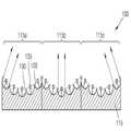
도 7은 백라이트 유닛(100)의 일 예를 도시한 것이다. 상기 백라이트 유닛(100)은 복수 개의 셀을 포함하고, 각 셀별로 광의 출광 방향을 조절하는 출광 유닛(115)을 포함할 수 있다. 상기 복수 개의 셀은 예를 들어 제1셀(115a), 제2셀(115b), 제3셀(115b)을 포함할 수 있다. 하지만, 여기에 한정되는 것은 아니며, 상기 복수 개의 셀은 2차원 구조로 배열될 수 있으며, 그 개수나 사이즈는 디스플레이의 사이즈, 화소수, 해상도 등에 따라 변경될 수 있다.Fig. 7 shows an example of the
상기 출광 유닛(115)은 반사부(120)와 상기 반사부(120)에 대응되게 배치된 광원(125)을 포함할 수 있다. 상기 반사부(120)는 곡면 형상을 가지며, 상기 광원(125)에서 나온 광을 반사시키는 재질로 형성될 수 있다. 상기 광원(125)은 예를 들어 LED(Light Emitting Diode) 또는 OLED(Organic Light Emitting Diode)를 포함할 수 있다. 상기 반사부(120)는 각 셀 내에서 3차원 구조로 배열될 수 있으며, 예를 들어 곡면에 배열된 형태를 가질 수 있다. 이렇게 배열됨으로써 각 반사부(120)의 정방향이 서로 다르게 되어 각 반사부에서 반사되는 광의 방향이 다르게 된다. 상기 반사부(120)가 점대칭 구조로 배열될 수 있으며, 각 셀에서 광원(125)의 on-off를 조절하여 광의 출광 방향을 조절할 수 있다. 예를 들어, 제1셀(115a)에서는 첫 번째 광원을 on하고, 제2셀(115b)에서는 세 번째 광원을 on하고, 제3셀(115c)에서는 다섯 번째 광원을 on함으로써, 각 셀에서의 출광 방향을 조절할 수 있다. 각 셀에서의 광의 출광 방향은 on되는 광원의 위치에 따라 결정되며, 디스플레이 장치의 제어부(도 2의 16 참조)가 각 셀에서의 광원과 출광 방향의 대응 관계에 대한 데이터를 포함할 수 있다. 광의 출광 방향은 상기 반사부(120)의 배열 구조에 따라 디스플레이 장치의 좌우 방향, 상하 방향, 대각선 방향 등과 같이 다양한 방향으로 제어할 수 있다.The
상기 반사부(120)는 예를 들어 광원(125)의 위치를 일 초점으로 하고, 이 광원(125)에서 출사되고 상기 반사부(120)에서 반사된 광이 평행광이 되도록 된 포물경으로 구성될 수 있다. 상기 광원(125)은 각각에 대응되는 반사부(120)에 설치될 수 있으며, 단면에서 봤을 때 상기 광원(125)을 이은 가상의 선(130)이 곡선이 될 수 있다. 이와 같이 각 광원(125)의 위치와 반사부의 위치에 의한 조합을 이용하여 광의 출광 방향을 조절할 수 있고, 광을 좌안 방향과 우안 방향으로 분리하여 보냄으로써 3차원 영상을 표시할 수 있다. 그리고, 시간 순차적으로 좌안 영상과 우안 영상을 표시함으로써 해상도의 저하 없이 3차원 영상을 표시할 수 있다. 즉, 제1프레임에서는 백라이트 유닛의 각 셀별로 on되는 광원의 위치를 조절하여 광이 좌안을 비추도록 하고, 디스플레이 패널에서는 좌안용 영상을 형성한다. 그리고, 제2프레임에서는 광이 우안만을 비추도록 백라이트 유닛의 각 셀별로 광원의 on 위치를 변경한다. 이때, 디스플레이 패널에서는 우안용 영상을 형성한다.The
한편, 각 셀에서 동일한 위치, 예를 들어 각 셀의 중심에 있는 광원을 on하여 광이 디스플레이의 정면으로 향하도록 함으로써 2차원 영상을 표시할 수 있다. 또는, 각 셀에 있는 모든 광원을 on함으로써도 2차원 영상을 표시할 수 있다. 이와 같이 각 셀마다 광의 출광 방향을 조절함으로써 용이하게 2차원 영상과 3차원 영상을 선택적으로 표시할 수 있다.On the other hand, a two-dimensional image can be displayed by turning on a light source at the same position in each cell, for example, the center of each cell, and directing the light toward the front of the display. Alternatively, two-dimensional images can be displayed by turning on all the light sources in each cell. As described above, the two-dimensional image and the three-dimensional image can be selectively displayed easily by adjusting the outgoing direction of light for each cell.
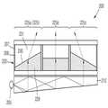
도 8은 다른 예에 따른 백라이트 유닛(200)을 도시한 것이다. 상기 백라이트 유닛(200)은 광원(205)과, 상기 광원(205)으로부터 출사된 광을 가이드하는 도광판(210)과, 상기 도광판(210) 위에 광의 출광 방향을 조절하는 프리즘 어레이(220)를 포함할 수 있다. 상기 광원(205)은 CCFL(Cold Cathod Fluorescent Lamp), LED, 또는 OLED 등을 포함할 수 있다. 상기 도광판(210)은 상기 광원(205)에서 나온 광을 상기 프리즘 어레이(220)쪽으로 향하도록 가이드한다. 또한, 상기 도광판(210)은 광을 콜리메이팅시켜 점광원이나 선광원을 면광원으로 만들어줄 수 있다. 상기 도광판(210)은 광을 콜리메이팅시키기 위해 웨지형으로 형성될 수 있다. 또는, 도면에 도시되지는 않았지만, 도광판의 상부면 또는 하부면에 프리즘 출광 패턴을 구비하여 광을 콜리메이팅시킬 수 있다. 이러한 프리즘 출광 패턴은 이미 널리 알려져 있다.8 shows a
상기 프리즘 어레이(220)는 상기 도광판(210) 위에 셀(225) 단위로 구획되고, 전기적 신호에 따라 굴절면(230)의 기울기를 조절함으로써 광의 출광 방향을 조절할 수 있다. 상기 셀(225)은 예를 들어 제1셀(225a), 제2셀(225b), 제3셀(225c)을 포함할 수 있다. 상기 제1셀(225a), 제2셀(225b), 및 제3셀(225c)에서의 굴절면(230)의 기울기를 조절하여 광이 진행하는 방향을 제어함으로써 광이 좌안과 우안으로 분리되어 들어가도록 할 수 있다. 그럼으로써, 3D 영상을 표시할 수 있다. 상기 프리즘 어레이(220)는 예를 들어 전기 습윤 소자(electric wetting device)를 포함할 수 있다. 상기 프리즘 어레이(220)는 전극(207)에 의해 셀별로 구획되고, 전극(207) 사이에는 물과 같은 분극성 액체(229)와, 기름과 같은 무극성 액체(231)가 구비될 수 있다. 상기 분극성 액체(229)와 무극성 액체(231) 사이의 경계면이 굴절면(230)이 된다. 상기 전극(207)의 내벽에는 유전체층(208)이 구비되고, 상기 유전체층(208)은 소수성(hydrophobic) 표면을 가진다. 상기 유전체층(208)은 소수성 박막을 유전체층의 상면에 코팅하거나 소수성 유전체층을 이용함으로써 형성될 수 있다. 전압이 인가되지 않은 경우 분극성 액체(229)는 상기 유전체층(208)과 높은 접촉각을 가지고 기울어지게 된다. 상기 전극(207)에 전압이 인가되면 상기 유전체층(208)과 분극성 액체(229)의 접촉각이 낮아지고, 그럼으로써 상기 굴절면(230)의 기울기가 변한다. 상기 굴절면(230)의 기울기가 변하면 광의 출광 방향이 변한다. 이와 같이, 상기 전극(207)에 전압을 on하거나 off하거나, 전압의 크기를 조절하여 광의 출광 방향을 제어할 수 있다. 여기서는, 상기 프리즘 어레이(220)가 전기 습윤의 원리를 이용하여 출광 방향을 조절하는 예를 설명하였지만, 이것에 한정되는 것은 아니다. 예를 들어, 편광된 광을 이용하여 영상을 형성하는 경우, 액정을 이용하여 출광 방향을 조절하는 것도 가능하다. 이 경우, 전극에 인가되는 전압에 의해 형성된 전기장의 크기에 따라 액정 분자 배열이 변함으로써 액정의 굴절력이 변하는 성질을 이용할 수 있다.The
도 8에 도시된 백라이트 유닛(200)에서는 상기 프리즘 어레이(220)에 인가되는 전압의 크기, 방향에 따라 광의 출광 방향을 조절할 수 있다. 예를 들어, 제1시점(t1)에서는 좌안으로 광을 보내고, 제2시점(t2)에서는 우안으로 광을 보내 3차원 영상을 구현할 수 있다. 이와 같이 시간 순차적으로 좌안 영상과 우안 영상을 표시하므로 해상도 저하 없이 3차원 영상을 표시할 수 있다. 한편, 각 셀별로 광이 정면을 향하도록 조절하여 2차원 영상을 표시하는 것도 가능하다. 그럼으로써, 2차원 영상과 3차원 영상의 전환이 가능하다.In the
다음, 도 9는 또 다른 실시예에 따른 백라이트 유닛(300)을 도시한 것이다. 상기 백라이트 유닛(300)은 복수 개의 셀을 포함하고, 상기 셀 별로 광의 출광 방향을 조절하는 출광 유닛(325)을 포함한다. 상기 출광 유닛(325)은 광을 선택적으로 on-off 스위칭하는 광 어레이와, 상기 광 어레이로부터 나온 광의 진행 방향을 한정하는 방향 조절부를 포함할 수 있다. 광 어레이는 광원(305), 상기 광원(305)으로부터 출사된 광을 가이드하는 도광판(310), 및 상기 도광판(310)의 상부에 구비된 셔터 어레이(327)를 포함할 수 있다. 상기 셔터 어레이(327) 상부에는 렌즈어레이(330)가 구비될 수 있다. 상기 렌즈 어레이(330)가 상기 셔터 어레이(327)를 통과한 광의 방향을 한정하는 방향 조절부로 작용할 수 있다.Next, FIG. 9 shows a
상기 광원(305)은 CCFL(Cold Cathod Fluorescent Lamp), LED, 또는 OLED 등을 포함할 수 있다. 하지만, 여기에 한정되는 것은 아니다. 상기 도광판(310)은 산란형 출광 패턴을 가질 수 있다.The
상기 셔터 어레이(327)는 셀 별로 복수 개의 셔터를 포함하며, 2차원 구조로 배열될 수 있다. 예를 들어, 상기 셔터 어레이(327)는 제1 내지 제5 셔터(327a)(327b)(327c)(327d)(327e)를 포함할 수 있다. 상기 제1 내지 제5 셔터(327a)(327b)(327c)(327d)(327e)는 액정 셔터, 전기 습윤 셔터(electric wetting shutter), 또는 FTIR(Frustrated Total Internal Reflection Shutter; 이하, FTIR 셔터라고 함)를 포함할 수 있다. FTIR 셔터는 광을 리사이클하여 사용함으로써 소비 전력을 감소시킬 수 있다.The
상기 렌즈 어레는(330)는 각 셀별로 렌즈가 구비되고, 상기 렌즈 어레이(330)의 초점 면에 셔터 어레이(327)가 구비될 수 있다. 예를 들어, 상기 셀이 2차원 구조를 가지는 경우, 상기 렌즈 어레이(330)도 2차원 배열 구조를 가질 수 있다. 상기 렌즈 어레이(330)와 셔터 어레이(327) 사이에 초점 거리로 간격을 두기 위해 스페이스층(329)이 더 구비될 수 있다. 상기 스페이스층(329)은 상기 렌즈 어레이(330)와 같은 굴절률을 가지는 재질로 형성되거나, 일체형으로 형성될 수 있다. 상기 셔터 어레이(327)와 도광판(310) 사이에 도광판(310)에서 나온 광을 균일하게 퍼지게 하기 위한 확산판(312), 광 진행 경로를 보정하기 위한 프리즘 시트(314), 밝기 향상 필름(316)이 더 구비될 수 있다.The
광원(305)에서 출사된 광이 도광판(310)을 통해 백라이트 유닛(300)의 전면에 퍼지게 되어 상기 광원(305)이 면광원으로 전환된다. 상기 도광판(310)에서 위쪽으로 나온 광은 상기 셔터 어레이(327)의 개폐 동작에 따라 광의 on-off가 제어되며, 개방된 셔터의 위치와 렌즈 어레이(330)의 협동에 의해 광의 진행 방향이 달라진다. 예를 들어, 상기 제1셀(325a)에서 제1 셔터(327a)가 개방되고, 나머지 셔터들이 폐쇄될 때, 광이 도면상 우측 상부로 향할 수 있다. 제2셀(325b)에서 제3셔터(327c)가 개방되고 나머지 셔터들이 폐쇄될 때, 광이 도면상 정면으로 향할 수 있다. 제3셀(325c)에서 제5셔터(327e)가 개방되고, 나머지 셔터들이 폐쇄될 때 광이 도면상 좌측 상부로 향할 수 있다. 이와 같이 각 셀마다 광의 출광 방향을 조절함으로써 좌안과 우안의 시역을 분리하여 3D 영상을 표시할 수 있다. 개방되는 셔터의 위치와, 이에 대응되는 셔터의 위치의 조합을 이용하여 광의 출광 방향을 다양하게 조절할 수 있다. 셔터 어레이가 2차원 구조를 가지는 경우 광의 출광 방향은 상하 좌우 자유롭게 조절할 수 있다. 따라서, 디스플레이의 표시 방향을 자유롭게 전환할 수 있고, 그럼으로써 포트레이트 표시 방식과 랜드스케이프 표시 방식 모두가 구현될 수 있다.The light emitted from the
한편, 상기 셔터 어레이(327)의 셔터 개방 위치를 조절하여 2차원 영상을 표시할 수 있다. 예를 들어, 상기 셔터 어레이(327)의 모든 셔터를 개방하거나, 각 셀 별로 동일한 위치에 있는 하나 이상의 셔터를 개방함으로써 2차원 영상을 표시할 수 있다. 이와 같이 셔터 어레이의 개방 위치를 조절하여 2차원 영상과 3차원 영상의 전환을 용이하게 할 수 있다. 또한, 시간 순차적으로 좌안 영상과 우안 영상을 표시하여 해상도의 저하 없이 3차원 영상을 표시할 수 있다.On the other hand, a two-dimensional image can be displayed by adjusting the shutter opening position of the
도 10은 또 다른 실시예에 따른 백라이트 유닛(400)을 도시한 것이다. 상기 백라이트 유닛(400)은 복수 개의 셀(430)로 구획되고, 각 셀별로 광을 출광 방향을 조절하는 출광 유닛(420)을 포함한다. 상기 출광 유닛(420)은 복수 개의 광원이 배열된 광원 어레이(415)와, 상기 광원 어레이(415) 상부에 구비된 핀홀(425)을 포함한다. 상기 광원 어레이는 LED 또는 OLED를 포함할 수 있다. 상기 핀홀(425)은 각 셀(430)에 하나씩 구비될 수 있다. 도 10에서는 상기 광원 어레이(415)가 각 광원의 on-off를 스위칭할 수 있는 광 어레이로 구비된다. 도 9와 비교할 때, 광원(305), 도광판(310), 셔터 어레이(327)가 도 6에서는 광원 어레이(415)에 의해 대체되고, 광원 어레이(415)가 광 어레이 기능을 수행하는 것이다. 상기 광원 어레이(415)는 2차원 구조를 가질 수 있다. 예를 들어, 상기 광원 어레이(415)는 제1 내지 제5 광원(415a)(415b)(415c)(415d)(415e)을 포함할 수 있다. 상기 광원 어레이(415)의 광원 중 on 되는 광원과, 그에 대응되는 핀홀(425)의 협동에 의해 광의 진행 방향이 한정될 수 있다.Fig. 10 shows a
예를 들어, 상기 복수 개의 셀은 제1셀(430a), 제2셀(430b), 제3셀(430c)을 포함할 수 있다. 제1셀(430a)에서 제1광원(415a)이 on되고, 나머지 광원이 off일 때, 제1광원(415a)으로부터의 광이 핀홀(425)을 통해 도면 상 우측 상부로 진행할 수 있다. 제2셀(430b)에서 제3광원(415c)이 on되고, 나머지 광원이 off일 때, 제3광원(415c)으로부터의 광이 핀홀(425)을 통해 상부로 진행할 수 있다. 제3셀(430c)에서 제5광원(415e)이 on이고 나머지 광원이 off일 때, 광이 핀홀(425)을 통해 도면 상 좌측 상부로 진행할 수 있다. 도면에서는 각 셀마다 광의 출광 방향을 독립적으로 조절할 수 있는 것을 보여주기 위해 서로 다른 방향으로 가는 광을 보여준 것이며, 예를 들어 광을 우안으로 보내거나 좌안으로 보내는 경우 각 셀에서의 on되는 광원의 위치와 핀홀(425)의 조합에 따른 출광 방향에 따라 좌안 또는 우안으로 광을 분리하여 보낼 수 있다. 즉, 핀홀과 불이 켜진 광원의 상대적인 위치를 이용하여 광을 원하는 방향으로 보낼 수 있다. 그럼으로써, 3D 영상을 표시할 수 있다. 각 셀의 광원 어레이에서 두 개 이상의 광을 동시에 on하는 것도 가능하다. 한편, 상기 광원 어레이(415)에서 각 셀마다 동일한 위치에 있는 하나 이상의 광원을 on함으로써 2차원 영상을 표시할 수 있다. 이와 같이 상기 백라이트 유닛(400)은 광원 어레이에서 on되는 광원의 위치를 조절함으로써 간단하게 2차원 영상과 3차원 영상이 전환이 가능하다. 또한, 3차원 영상의 구현시, 좌안 영상과 우안 영상 각각에 대해 디스플레이 패널의 전체 영역을 사용하므로 해상도의 저하없이 3차원 영상의 구현이 가능하다.For example, the plurality of cells may include a
한편, 본 발명의 실시예에 따른 디스플레이는 리프레쉬 레이트를 증가시켜 뷰(2 view) 이상의 영상을 표시할 수 있다. 한 주기의 화면을 한 프레임이라고 하고, 한 프레임에 포함되는 각 시점(view)의 화면에 대응되는 스캐닝 속도를 리프레쉬 레이트라고 한다. 예를 들어, 한 프레임의 주파수가 60Hz이고, 한 프레임이 4 뷰를 구현하기 위해서는, 240Hz 이상의 리프레쉬 레이트가 필요하다. 이와 같이 리프레쉬 레이트를 조절하고, 이 리스레쉬 레이트에 대응되는 속도를 가지고 출광 유닛이 각 뷰에 대응되는 방향으로 출광 방향을 조절하여 광을 보냄으로써 4 뷰의 3차원 영상을 표시할 수 있다. 여기서는 4뷰를 예로 들어 설명한 것이고, 그 이상의 다시점 3차원 영상을 표시하는 것도 가능하다.Meanwhile, the display according to the embodiment of the present invention can display an image of a view (2 view) or more by increasing the refresh rate. A screen of one cycle is referred to as one frame, and a scanning rate corresponding to a screen of each view included in one frame is referred to as a refresh rate. For example, in order for a frame to have a frequency of 60 Hz and a frame to implement 4 views, a refresh rate of 240 Hz or more is required. By thus adjusting the refresh rate, the outgoing light unit adjusts the outgoing direction in a direction corresponding to each view with a speed corresponding to the resereal rate, and transmits light, thereby displaying a three-dimensional image of four views. In this example, four views are exemplified, and it is also possible to display a multi-view three-dimensional image.
상술한 바와 같이 백라이트 유닛의 출광 유닛에서 광의 출광 방향을 조절하여 선택적으로 3D 영상을 표시하거나, 2D 영상을 표시할 수 있다. 각 셀의 출광 유닛 조절하여 2D 영상과 3D 영상을 서로 다른 시간에 선택적으로 표시하는 것도 가능한 한편, 2D 영상과 3D 영상을 하나의 화면에서 동시에 표시하는 것도 가능하다.As described above, it is possible to selectively display a 3D image or a 2D image by adjusting the outgoing direction of light in the light output unit of the backlight unit. It is possible to selectively display the 2D image and the 3D image at different times by adjusting the light emission unit of each cell, and simultaneously display the 2D image and the 3D image on one screen.
도 2를 참조하여 설명한 셔터 패턴 형성부(14)에서 하나의 화면에서 2D 영상 영역과 3D 영상 영역에 대응되는 셔터 패턴을 형성하고, 이 셔터 패턴에 따라 제어부(16)에서 백라이트 유닛(17)의 각 셀의 출광 유닛을 제어할 수 있다.A shutter pattern corresponding to the 2D image area and the 3D image area is formed on one screen in the shutter pattern forming part 14 described with reference to FIG. 2, and the
예를 들어, 도 11a 및 도 11b는 도 7에 도시된 백라이트 유닛(100)을 이용하여 2D 영상과 3D 영상을 표시하는 것을 보여준다. 예를 들어, 도 11a는 제1셔터 패턴을, 도 11b는 제2셔터 패턴을 보여준다. 도 11a를 참조하면, 제1셔터 패턴의 2D 영상 영역에 대해서는 각 셀의 출광 유닛(115)에서 모든 광원이 on되고, 3D 영상 영역에 대해서는 각 셀의 출광 유닛(115)에서 좌안으로 광이 출광되도록 예를 들어 각 셀의 네 번째 광원이 on되고 나머지 광원은 off 될 수 있다. 도 11b를 참조하면, 제2셔터 패턴의 2D 영상에 대해서는 각 셀의 출광 유닛(115)에서 모든 광원이 on되고, 3D 영상 영역에 대해서는 각 셀의 출광 유닛(115)에서 우안으로 광이 출광되도록 예를 들어 각 셀의 두 번째 광원이 on되고 나머지 광원은 off 될 수 있다. 하지만, 이것은 일 예일 뿐이며 여기에 한정되는 것은 아니다. 예를 들어, 우안으로 광이 출광되도록 3D 영상 영역의 모든 셀에서 두 번째 광원이 on되지 않고, 3D 영상 영역의 위치마다 각 셀에서 on 되는 광원의 위치가 달라질 수 있다.For example, FIGS. 11A and 11B show 2D images and 3D images using the
도 12a 및 도 12b는 도 9에 도시된 백라이트 유닛(300)을 이용하여 2D 영상과 3D 영상을 표시하는 것을 보여준다. 예를 들어, 도 12a는 제1셔터 패턴을, 도 12b는 제2셔터 패턴을 보여준다. 도 12a를 참조하면, 제1셔터 패턴의 2D 영상 영역에 대해서는 각 셀의 출광 유닛(325)에서 모든 셔터가 on되고, 3D 영상 영역에 대해서는 각 셀의 출광 유닛(325)에서 좌안으로 광이 출광되도록 예를 들어 각 셀의 제2 셔터(327b)가 on되고 나머지 셔터는 off 될 수 있다. 여기서, 셔터가 on 되는 것은 셔터가 개방되는 것이고, 셔터가 off 되는 것은 셔터가 폐쇄되는 것을 나타낸다. 도 12b를 참조하면, 제2셔터 패턴의 2D 영상에 대해서는 각 셀의 출광 유닛(325)에서 모든 셔터가 on되고, 3D 영상 영역에 대해서는 각 셀의 출광 유닛(325)에서 우안으로 광이 출광되도록 예를 들어 각 셀의 제4 셔터(327d)가 on되고 나머지 광원은 off 될 수 있다.12A and 12B show the 2D image and the 3D image displayed using the
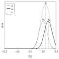
한편, 도 13a 및 도 13b는 도 9에 도시된 백라이트 유닛(300)의 출광 유닛의 각 셀에서 on되는 셔터의 위치에 따라 광의 출광 각도가 달라짐을 보여준 것이다. 예를 들어, 도 13a에 도시된 바와 같이 제1셔터(327a)가 on 될 때, 제1셔터(327a)R를 통과한 제1광(LA)의 제1 출광 각도를 θA라고 하고, 도 13b에 도시된 바와 같이 제2셔터(327b)가 on 될 때, 제2셔터(327b)에서 나온 제2광(LB)의 제2 출광 각도를 θB라고 한다. 도 14는 출광 각도에 따른 광속을 도시한 것이다. 이와 같이, 출광 유닛의 on/off 신호에 따라 광의 출광 각도가 θA,θB와 같이불연속적으로 조절될 수 있다. 출광 각도 간격을 좀더 좁힘으로써 화면 크기나 시청 거리의 선택의 폭을 넓힐 수 있다. 출광 각도 간격을 좁히는 방법으로는 각 셀에서 셔터의 개수와 피치 간격 등을 조절하는 방법이 있을 수 있다. 하지만, 동일한 개수의 셔터를 가지고 출광 각도 간격을 조절하는 방법도 있다. 예를 들어, 상기 제1광(LA)의 제1출광 각도 θA와 제2광(LB)의 제2 출광 각도 θB사이에 있는 제3 출광 각도(θC;θA<θC<θB)를 얻기 위해, 출광 유닛의 각 셔터의 투과도를 조절할 수 있다. 도 15는 제1 출광 각도(θA)를 가지는 제1광(LA)과 제2 출광 각도(θB)를 가지는 제2광(LB)의 합성에 의해 제3 출광 각도(θC)를 가지는 광이 출광됨을 보여준다. 제3출광 각도(θC)는다음과 같이 제1광(LA)을 출광하는 제1셔터(327a)와 제2광(LB)를 출광하는 제2셔터(327b)의 투과도를 조절하여 얻을 수 있다.13A and 13B show that the outgoing angle of light varies depending on the position of the shutter turned on in each cell of the light-exiting unit of the
θC= (αθA + βθB)/2 ......... (식 1)?C = (??A +??B ) / 2 (1)
여기서, α는 상기 제1셔터(327a)의 투과도를, β는 제2셔터(327b)의 투과도에 의해 결정되는 함수를 각각 나타낸다. 셔터의 투과도는 편광에 의한 투과량 조절, 셔터의 단위 면적 당 투과가 일어나는 면적, 단위 시간 당 투과가 일어나는 시간 중 적어도 하나를 조절하여 조절할 수 있다. 이와 같이 제어할 수 있는 출광 각도의 간격을 좁힘으로써 화면의 크기나 시청 거리 등의 선택의 폭을 넓힐 수 있다.Here,? Represents the transmittance of the
상술한 바와 같이 본 발명의 실시예에 따른 입체 영상 디스플레이 장치 및 방법은 한 화면에서 2D 영상과 3D 영상을 동시에 표시할 수 있어 예를 들어 윈도우 형태의 여러 화면에서 각각에 적합한 2D 영상과 3D 영상을 효과적으로 표시할 수 있다.As described above, the stereoscopic image display apparatus and method according to the embodiment of the present invention can simultaneously display a 2D image and a 3D image on one screen. For example, a 2D image and a 3D image It can be displayed effectively.
본 발명의 실시예에 따른 입체 영상 디스플레이 장치 및 방법은 이해를 돕기 위하여 도면에 도시된 실시예를 참고로 설명되었으나, 이는 예시적인 것에 불과하며, 당해 분야에서 통상적 지식을 가진 자라면 이로부터 다양한 변형 및 균등한 타 실시예가 가능하다는 점을 이해할 것이다. 따라서, 본 발명의 진정한 기술적 보호 범위는 첨부된 특허청구범위에 의해 정해져야 할 것이다.The stereoscopic image display apparatus and method according to the embodiment of the present invention have been described with reference to the embodiments shown in the drawings in order to facilitate understanding. However, those skilled in the art will appreciate that various modifications And other equivalent embodiments are possible. Accordingly, the true scope of the present invention should be determined by the appended claims.
1...디스플레이 장치, 3,5...2D 영상 영역
7...3D 영상 영역, 10...입력부
12...마스크 패턴 형성부, 14...셔터 패턴 형성부
16...제어부, 17,70,100,200,300,400...백라이트 유닛
19,80...디스플레이 패널, 75,115,225,325,420...출광 유닛,
120...반사부, 125,205,305...광원,
220...프리즘 어레이, 327...셔터 어레이
425...핀홀1 ... display device, 3,5 ... 2D image area
7 ... 3D image area, 10 ... input part
12: mask pattern forming portion, 14: shutter pattern forming portion
16 ... control unit, 17,70,100,200,300,400 ... backlight unit
19,80 ... display panel, 75,115,225,325,420 ... exiting unit,
120 ... reflection part, 125,205,305 ... light source,
220 ... prism array, 327 ... shutter array
425 ... pinhole
Claims (23)
Translated fromKorean상기 입력부에서 입력된 3D 영상 영역에 대응되는 마스크 패턴을 형성하는 마스크 패턴 형성부;
상기 마스크 패턴을 이용하여 제1눈을 위한 제1 셔터 패턴과 제2눈을 위한 제2 셔터 패턴을 형성하는 셔터 패턴 형성부;
복수 개의 셀과, 상기 복수 개의 셀 별로 광의 진행 방향을 조절할 수 있도록 된 출광 유닛을 가지는 백라이트 유닛;
상기 제1 셔터 패턴과 제2 셔터 패턴에 따라 상기 출광 유닛에서 광의 진행 방향을 조절하여 상기 3D 영상 영역으로부터 3D 영상이 표시되고, 상기 2D 영상 영역으로부터 2D 영상이 표시되도록 하는 제어부; 및
상기 백라이트 유닛으로부터 출사된 광을 이용하여 영상을 형성하는 디스플레이 패널;을 포함하는 입체 영상 디스플레이 장치.An input unit for generating a 3D image region and a 2D image region;
A mask pattern forming unit for forming a mask pattern corresponding to the 3D image region input from the input unit;
A shutter pattern forming unit for forming a first shutter pattern for the first eye and a second shutter pattern for the second eye using the mask pattern;
A backlight unit having a plurality of cells and an outgoing unit capable of adjusting the traveling direction of light for each of the plurality of cells;
A control unit for controlling a progressing direction of light in the light output unit according to the first shutter pattern and the second shutter pattern to display a 3D image from the 3D image area and displaying a 2D image from the 2D image area; And
And a display panel for forming an image using light emitted from the backlight unit.
상기 입력부는 3D 영상 영역의 좌표를 생성하는 좌표 생성부를 포함하는 입체 영상 디스플레이 장치.The method according to claim 1,
Wherein the input unit includes a coordinate generator for generating coordinates of a 3D image area.
곡면에 2차원 어레이 형태로 배열되고, 곡면 형상을 가지는 복수 개의 반사부; 및
상기 반사부에 대응되게 마련되는 광원;을 포함하는 입체 영상 디스플레이 장치.The image forming apparatus according to claim 1 or 2,
A plurality of reflection parts arranged in a two-dimensional array on the curved surface and having a curved shape; And
And a light source provided corresponding to the reflective portion.
상기 반사부는 상기 광원으로부터의 광을 콜리메이팅 광으로 반사시키는 입체 영상 디스플레이 장치.The method of claim 3,
And the reflector reflects the light from the light source as collimating light.
상기 광원은 각각 독립적으로 제어되는 입체 영상 디스플레이 장치.The method of claim 3,
Wherein the light sources are independently controlled.
광원;
상기 광원으로부터의 광을 가이드하는 도광판; 및
상기 도광판 위에 상기 셀 단위로 구획되고, 전기적 신호에 따라 굴절면의 기울기를 조절할 수 있는 프리즘 어레이;를 포함하는 입체 영상 디스플레이 장치.The image forming apparatus according to claim 1 or 2,
Light source;
A light guide plate for guiding light from the light source; And
And a prism array partitioned by the cell unit on the light guide plate and capable of adjusting a tilt of a refracting surface according to an electrical signal.
상기 도광판은 웨지형으로 형성된 입체 영상 디스플레이 장치.The method according to claim 6,
Wherein the light guide plate is formed in a wedge shape.
상기 프리즘 어레이는 전기 습윤 소자를 포함하는 입체 영상 디스플레이 장치.The method according to claim 6,
Wherein the prism array includes an electrowetting element.
상기 프리즘 어레이는 2차원 어레이 구조를 가지는 입체 영상 디스플레이 장치.The method according to claim 6,
Wherein the prism array has a two-dimensional array structure.
광을 선택적으로 on-off 스위칭하는 광 어레이; 및
상기 광 어레이로부터 나온 광의 진행 방향을 한정하는 방향 조절부;를 포함하는 입체 영상 디스플레이 장치.The image forming apparatus according to claim 1 or 2,
An optical array for selectively on-off switching the light; And
And a direction adjusting unit that defines a traveling direction of light emitted from the optical array.
광원;
상기 광원으로부터의 광을 가이드하는 도광판;
상기 도광판 위에 셀 별로 구비된 것으로 각각 독립적으로 개폐되는 복수 개의 셔터를 가지는 셔터 어레이; 및
상기 셔터 어레이 위에 구비된 렌즈 어레이;를 포함하는 입체 영상 디스플레이 장치.The image forming apparatus according to claim 1 or 2,
Light source;
A light guide plate for guiding light from the light source;
A shutter array having a plurality of shutters independently provided on a cell-by-cell basis on the light guide plate; And
And a lens array provided on the shutter array.
상기 셔터 어레이는 액정 셔터, 전기 습윤 셔터, 또는 FTIR(Frustrated Total Internal Reflection) 셔터를 포함하는 입체 영상 디스플레이 장치.12. The method of claim 11,
Wherein the shutter array includes a liquid crystal shutter, an electrowetting shutter, or a frustrated total internal reflection (FTIR) shutter.
상기 셔터 어레이는 2차원 구조로 배열되는 입체 영상 디스플레이 장치.12. The method of claim 11,
Wherein the shutter array is arranged in a two-dimensional structure.
상기 셀의 이웃하는 셔터의 투과도를 조절하여 광의 출광 각도가 조절되는 입체 영상 디스플레이 장치.12. The method of claim 11,
Wherein an outgoing light angle of the light is adjusted by adjusting a transmittance of an adjacent shutter of the cell.
상기 셔터의 투과도는 편광에 의한 투과량 조절, 셔터의 단위 면적 당 투과가 일어나는 면적, 단위 시간 당 투과가 일어나는 시간 중 적어도 하나를 변화시켜 조절되는 입체 영상 디스플레이 장치.15. The method of claim 14,
Wherein the transmittance of the shutter is adjusted by changing at least one of a transmittance control by polarized light, an area where transmission per unit area of the shutter occurs, and a time of transmission per unit time.
상기 셀 단위로 구비되고, 각각 독립적으로 on-off 조절되는 복수 개의 광원을 가지는 광원 어레이; 및
상기 각 셀에 대응되게 구비되어 상기 복수 개의 광원에서 출사된 광의 진행 방향을 한정하는 핀홀 어레이;를 포함하는 입체 영상 디스플레이 장치.The image forming apparatus according to claim 1 or 2,
A light source array having a plurality of light sources provided on a cell-by-cell basis, the light sources being independently controlled on-off; And
And a pinhole array corresponding to each of the cells to define a traveling direction of light emitted from the plurality of light sources.
상기 제1 셔터 패턴은 2D 영상을 위한 패턴과 좌안 영상을 위한 패턴을 포함하고, 제2 셔터 패턴은 2D 영상을 위한 패턴과 우안 영상을 위한 패턴을 포함하는 입체 영상 디스플레이 장치.3. The method according to claim 1 or 2,
Wherein the first shutter pattern includes a pattern for a 2D image and a pattern for a left eye image, and the second shutter pattern includes a pattern for a 2D image and a pattern for a right eye image.
상기 3D 영상 영역에 대응되는 마스크 패턴을 형성하는 단계;
상기 마스크 패턴을 이용하여 제1눈을 위한 제1 셔터 패턴과 제2눈을 위한 제2 셔터 패턴을 형성하는 단계;
복수 개의 셀과, 상기 셀 별로 광의 진행 방향을 조절할 수 있도록 된 출광 유닛을 포함하는 백라이트 유닛의 상기 각 셀에서의 출광 방향을 상기 제1 셔터 패턴과 제2 셔터 패턴에 따라 조절하여 광을 출력하는 단계;
상기 제1 셔터 패턴과 제2 셔터 패턴에 따라 상기 출광 유닛에서 광의 진행 방향을 조절하여 상기 3D 영상 영역으로부터 3D 영상을 표시하고, 상기 2D 영상 영역으로부터 2D 영상을 표시하는 단계;를 포함하는 입체 영상 표시 방법.Inputting a 2D image area and a 3D image area;
Forming a mask pattern corresponding to the 3D image area;
Forming a first shutter pattern for the first eye and a second shutter pattern for the second eye using the mask pattern;
The light output direction of each of the cells of the backlight unit including a plurality of cells and an outgoing unit capable of adjusting the traveling direction of each cell is adjusted according to the first shutter pattern and the second shutter pattern to output light step;
And displaying a 3D image from the 3D image area by adjusting the traveling direction of light in the light output unit according to the first shutter pattern and the second shutter pattern and displaying a 2D image from the 2D image area, Display method.
상기 제1 셔터 패턴은 2D 영상용 패턴과 좌안용 패턴을 포함하고, 제2 셔터 패턴은 2D 영상용 패턴과 우안용 패턴을 포함하는 입체 영상 표시 방법.19. The method of claim 18,
Wherein the first shutter pattern includes a 2D image pattern and the left eye pattern, and the second shutter pattern includes a 2D image pattern and a right eye pattern.
광원;
상기 광원으로부터의 광을 가이드하는 도광판;
상기 도광판 위에 셀 별로 구비된 것으로 각각 독립적으로 개폐되는 복수 개의 셔터를 가지는 셔터 어레이; 및
상기 셔터 어레이 위에 구비된 렌즈 어레이;를 포함하는 입체 영상 표시 방법.The image forming apparatus according to claim 18 or 19,
Light source;
A light guide plate for guiding light from the light source;
A shutter array having a plurality of shutters independently provided on a cell-by-cell basis on the light guide plate; And
And a lens array disposed on the shutter array.
상기 셔터 어레이는 액정 셔터, 전기 습윤 셔터, 또는 FTIR(Frustrated Total Internal Reflection) 셔터를 포함하는 입체 영상 표시 방법.21. The method of claim 20,
Wherein the shutter array includes a liquid crystal shutter, an electrowetting shutter, or a frustrated total internal reflection (FTIR) shutter.
상기 셀의 이웃하는 셔터의 투과도를 조절하여 광의 출광 각도를 조하는 입체 영상 표시 방법.21. The method of claim 20,
And adjusting an output angle of light by adjusting a transmittance of an adjacent shutter of the cell.
상기 셔터의 투과도는 편광에 의한 투과량 조절, 셔터의 단위 면적 당 투과가 일어나는 면적, 단위 시간 당 투과가 일어나는 시간 중 적어도 하나를 변화시켜 조절되는 입체 영상 표시 방법.23. The method of claim 22,
Wherein the transmittance of the shutter is adjusted by varying at least one of a transmittance adjustment by polarized light, an area where transmission per unit area of the shutter occurs, and a transmission time per unit time.
Priority Applications (2)
| Application Number | Priority Date | Filing Date | Title |
|---|---|---|---|
| KR1020100087668AKR101652401B1 (en) | 2010-09-07 | 2010-09-07 | 3D image display apparatus and 3D image display method |
| US13/215,163US9049441B2 (en) | 2010-09-07 | 2011-08-22 | 3D image display apparatus and method |
Applications Claiming Priority (1)
| Application Number | Priority Date | Filing Date | Title |
|---|---|---|---|
| KR1020100087668AKR101652401B1 (en) | 2010-09-07 | 2010-09-07 | 3D image display apparatus and 3D image display method |
Publications (2)
| Publication Number | Publication Date |
|---|---|
| KR20120025342A KR20120025342A (en) | 2012-03-15 |
| KR101652401B1true KR101652401B1 (en) | 2016-08-31 |
Family
ID=45770365
Family Applications (1)
| Application Number | Title | Priority Date | Filing Date |
|---|---|---|---|
| KR1020100087668AActiveKR101652401B1 (en) | 2010-09-07 | 2010-09-07 | 3D image display apparatus and 3D image display method |
Country Status (2)
| Country | Link |
|---|---|
| US (1) | US9049441B2 (en) |
| KR (1) | KR101652401B1 (en) |
Families Citing this family (14)
| Publication number | Priority date | Publication date | Assignee | Title |
|---|---|---|---|---|
| US9094660B2 (en)* | 2010-11-11 | 2015-07-28 | Georgia Tech Research Corporation | Hierarchical hole-filling for depth-based view synthesis in FTV and 3D video |
| JP5306494B2 (en)* | 2012-01-31 | 2013-10-02 | 株式会社東芝 | Electronic device and display control method |
| MX2014012615A (en)* | 2012-04-24 | 2015-01-15 | Koninkl Philips Nv | Auto-stereoscopic display device and driving method. |
| US9800862B2 (en)* | 2012-06-12 | 2017-10-24 | The Board Of Trustees Of The University Of Illinois | System and methods for visualizing information |
| CN103676164A (en)* | 2012-09-19 | 2014-03-26 | 瀚宇彩晶股份有限公司 | Local stereoscopic image display system, local stereoscopic image display method and adjustment method thereof |
| KR101944508B1 (en)* | 2012-11-20 | 2019-02-01 | 삼성디스플레이 주식회사 | Display device, apparatus for signal control device of the same and signal control method |
| US20150228226A1 (en)* | 2014-02-13 | 2015-08-13 | Nvidia Corporation | Power-efficient steerable displays |
| KR102208960B1 (en) | 2014-04-09 | 2021-01-28 | 삼성전자주식회사 | Holographic display |
| KR20160089600A (en)* | 2015-01-19 | 2016-07-28 | 삼성디스플레이 주식회사 | Display device |
| CN104698647B (en)* | 2015-04-07 | 2017-08-08 | 合肥京东方显示光源有限公司 | liquid crystal display device and its control method |
| US10186188B2 (en)* | 2015-09-23 | 2019-01-22 | Motorola Solutions, Inc. | Multi-angle simultaneous view light-emitting diode display |
| US10999573B2 (en)* | 2018-04-25 | 2021-05-04 | Raxium, Inc. | Partial light field display architecture |
| US20210165242A1 (en)* | 2018-06-26 | 2021-06-03 | Kyocera Corporation | Information display device and information display system |
| CN117116217A (en)* | 2022-12-26 | 2023-11-24 | 深圳Tcl新技术有限公司 | Display method, display device and storage medium |
Citations (2)
| Publication number | Priority date | Publication date | Assignee | Title |
|---|---|---|---|---|
| US20040056948A1 (en)* | 2002-09-23 | 2004-03-25 | Gibson Robert John | Multi-play theatre |
| US20090315981A1 (en)* | 2008-06-24 | 2009-12-24 | Samsung Electronics Co., Ltd. | Image processing method and apparatus |
Family Cites Families (28)
| Publication number | Priority date | Publication date | Assignee | Title |
|---|---|---|---|---|
| DE69432283T2 (en)* | 1993-12-01 | 2004-01-22 | Sharp K.K. | Display for three-dimensional images |
| GB2294350A (en) | 1994-10-21 | 1996-04-24 | Sharp Kk | Light source and display |
| US5761314A (en)* | 1994-01-27 | 1998-06-02 | Sony Corporation | Audio reproducing apparatus and headphone |
| JP3687099B2 (en)* | 1994-02-14 | 2005-08-24 | ソニー株式会社 | Video signal and audio signal playback device |
| US6252707B1 (en)* | 1996-01-22 | 2001-06-26 | 3Ality, Inc. | Systems for three-dimensional viewing and projection |
| US5973831A (en)* | 1996-01-22 | 1999-10-26 | Kleinberger; Paul | Systems for three-dimensional viewing using light polarizing layers |
| US6023277A (en)* | 1996-07-03 | 2000-02-08 | Canon Kabushiki Kaisha | Display control apparatus and method |
| JP2001281459A (en) | 2000-03-31 | 2001-10-10 | Fujitsu Ltd | Backlight device |
| US7084841B2 (en) | 2000-04-07 | 2006-08-01 | Tibor Balogh | Method and apparatus for the presentation of three-dimensional images |
| JP3647376B2 (en)* | 2001-01-31 | 2005-05-11 | キヤノン株式会社 | Viewpoint position detection apparatus, viewpoint position detection method, and stereoscopic image display system |
| JP2002286968A (en)* | 2001-03-28 | 2002-10-03 | Seiko Instruments Inc | Optical functional module |
| KR100970721B1 (en)* | 2003-07-29 | 2010-07-16 | 삼성전자주식회사 | High resolution three dimensional image display |
| DE10339076B4 (en)* | 2003-08-26 | 2007-10-31 | Seereal Technologies Gmbh | Autostereoscopic multi-user display |
| CN101930118B (en)* | 2003-10-08 | 2013-05-29 | 伊英克公司 | Electro-wetting displays |
| GB0403932D0 (en) | 2004-02-21 | 2004-03-24 | Koninkl Philips Electronics Nv | Improving image quality in a 3D image display device |
| WO2006015562A1 (en)* | 2004-08-10 | 2006-02-16 | Seereal Technologies Gmbh | Sweet-spot image separation device for autostereoscopic multi-user displays |
| KR101189080B1 (en)* | 2005-01-24 | 2012-11-09 | 삼성디스플레이 주식회사 | Reflecting plate and liquid crystal display device having the same |
| KR100813977B1 (en) | 2005-07-08 | 2008-03-14 | 삼성전자주식회사 | High resolution 2D-3D switchable autostereoscopic display apparatus |
| KR101159336B1 (en) | 2005-08-01 | 2012-06-22 | 엘지디스플레이 주식회사 | Liquid crystal display device for display from dual image and 3-dimension image |
| JP4600218B2 (en) | 2005-08-29 | 2010-12-15 | カシオ計算機株式会社 | Surface light source and liquid crystal display device |
| KR100728113B1 (en) | 2005-10-20 | 2007-06-13 | 삼성에스디아이 주식회사 | Stereoscopic Display and Driving Method |
| US7518619B2 (en)* | 2005-11-07 | 2009-04-14 | General Electric Company | Method and apparatus for integrating three-dimensional and two-dimensional monitors with medical diagnostic imaging workstations |
| DE102006018689A1 (en)* | 2006-04-13 | 2007-10-25 | Seereal Technologies S.A. | Method for rendering and generating computer-generated video holograms in real time |
| KR101309313B1 (en) | 2006-06-30 | 2013-09-13 | 엘지디스플레이 주식회사 | 3-dimension display device using devided screen |
| KR101315467B1 (en) | 2006-11-29 | 2013-10-04 | 삼성전자주식회사 | Backlight unit and display apparatus comprising the same |
| US7884823B2 (en)* | 2007-06-12 | 2011-02-08 | Microsoft Corporation | Three dimensional rendering of display information using viewer eye coordinates |
| US7753544B2 (en) | 2007-06-29 | 2010-07-13 | Sumitomo Chemical Company, Limited | Light control plate, surface light source device and transmissive image display device |
| DE102009003069A1 (en)* | 2009-05-13 | 2010-11-25 | Seereal Technologies S.A. | 3D display with controllable visibility tracker |
- 2010
- 2010-09-07KRKR1020100087668Apatent/KR101652401B1/enactiveActive
- 2011
- 2011-08-22USUS13/215,163patent/US9049441B2/enactiveActive
Patent Citations (2)
| Publication number | Priority date | Publication date | Assignee | Title |
|---|---|---|---|---|
| US20040056948A1 (en)* | 2002-09-23 | 2004-03-25 | Gibson Robert John | Multi-play theatre |
| US20090315981A1 (en)* | 2008-06-24 | 2009-12-24 | Samsung Electronics Co., Ltd. | Image processing method and apparatus |
Also Published As
| Publication number | Publication date |
|---|---|
| KR20120025342A (en) | 2012-03-15 |
| US9049441B2 (en) | 2015-06-02 |
| US20120056879A1 (en) | 2012-03-08 |
Similar Documents
| Publication | Publication Date | Title |
|---|---|---|
| KR101652401B1 (en) | 3D image display apparatus and 3D image display method | |
| KR20110109565A (en) | Backlight unit, 3D display and 3D image forming method having the same | |
| CN112363268B (en) | Directional backlight | |
| KR101800704B1 (en) | 3D image display apparatus | |
| JP3930021B2 (en) | Display device and electronic apparatus equipped with display device | |
| JP4404311B2 (en) | Multi-view directional display | |
| KR101660411B1 (en) | Super multi-view 3D display apparatus | |
| CN106662773A (en) | Directional privacy display | |
| KR20120111401A (en) | 3d image display apparatus | |
| JP5767293B2 (en) | Display device including line light source and driving method thereof | |
| KR20120069432A (en) | 3d image display apparatus and driving method thereof | |
| CN106576161A (en) | Variable barrier pitch correction | |
| JP2010237416A (en) | 3D display device | |
| EP3274761B1 (en) | Display device with directional control of the output, and a backlight for such a display device and a light direction method | |
| KR102070800B1 (en) | Stereoscopic display apparatus, and display method thereof | |
| KR20070120840A (en) | Image display device for displaying an enlarged image and image display method using the same | |
| JP2007179059A (en) | Portable device | |
| JP2011253028A (en) | Image display device and electronic apparatus using the same | |
| KR101606119B1 (en) | Method for displaying stereo-scopic image and stereo-scopic image display device for performing the same | |
| KR102598709B1 (en) | Backlight unit using micro optical switch, and display apparatus having the same | |
| KR20170044906A (en) | Back light apparatus and three dimentional image display apparatus comprising the same | |
| CN108732772A (en) | A kind of display equipment and its driving method | |
| KR20170128193A (en) | Backlight unit, 3D display having the same and method of making 3D image | |
| KR20170005507A (en) | Backlight unit, 3D display having the same and method of making 3D image | |
| KR102293367B1 (en) | Display device for displying 2-dimension and 3-dimension images |
Legal Events
| Date | Code | Title | Description |
|---|---|---|---|
| PA0109 | Patent application | St.27 status event code:A-0-1-A10-A12-nap-PA0109 | |
| PG1501 | Laying open of application | St.27 status event code:A-1-1-Q10-Q12-nap-PG1501 | |
| R18-X000 | Changes to party contact information recorded | St.27 status event code:A-3-3-R10-R18-oth-X000 | |
| A201 | Request for examination | ||
| PA0201 | Request for examination | St.27 status event code:A-1-2-D10-D11-exm-PA0201 | |
| E902 | Notification of reason for refusal | ||
| PE0902 | Notice of grounds for rejection | St.27 status event code:A-1-2-D10-D21-exm-PE0902 | |
| P11-X000 | Amendment of application requested | St.27 status event code:A-2-2-P10-P11-nap-X000 | |
| P13-X000 | Application amended | St.27 status event code:A-2-2-P10-P13-nap-X000 | |
| P22-X000 | Classification modified | St.27 status event code:A-2-2-P10-P22-nap-X000 | |
| E701 | Decision to grant or registration of patent right | ||
| PE0701 | Decision of registration | St.27 status event code:A-1-2-D10-D22-exm-PE0701 | |
| GRNT | Written decision to grant | ||
| PR0701 | Registration of establishment | St.27 status event code:A-2-4-F10-F11-exm-PR0701 | |
| PR1002 | Payment of registration fee | St.27 status event code:A-2-2-U10-U11-oth-PR1002 Fee payment year number:1 | |
| PG1601 | Publication of registration | St.27 status event code:A-4-4-Q10-Q13-nap-PG1601 | |
| P22-X000 | Classification modified | St.27 status event code:A-4-4-P10-P22-nap-X000 | |
| P22-X000 | Classification modified | St.27 status event code:A-4-4-P10-P22-nap-X000 | |
| PR1001 | Payment of annual fee | St.27 status event code:A-4-4-U10-U11-oth-PR1001 Fee payment year number:4 | |
| PR1001 | Payment of annual fee | St.27 status event code:A-4-4-U10-U11-oth-PR1001 Fee payment year number:5 | |
| PR1001 | Payment of annual fee | St.27 status event code:A-4-4-U10-U11-oth-PR1001 Fee payment year number:6 | |
| PR1001 | Payment of annual fee | St.27 status event code:A-4-4-U10-U11-oth-PR1001 Fee payment year number:7 | |
| PR1001 | Payment of annual fee | St.27 status event code:A-4-4-U10-U11-oth-PR1001 Fee payment year number:8 | |
| PR1001 | Payment of annual fee | St.27 status event code:A-4-4-U10-U11-oth-PR1001 Fee payment year number:9 | |
| PR1001 | Payment of annual fee | St.27 status event code:A-4-4-U10-U11-oth-PR1001 Fee payment year number:10 |