KR101652301B1 - Vibrator - Google Patents
VibratorDownload PDFInfo
- Publication number
- KR101652301B1 KR101652301B1KR1020140124275AKR20140124275AKR101652301B1KR 101652301 B1KR101652301 B1KR 101652301B1KR 1020140124275 AKR1020140124275 AKR 1020140124275AKR 20140124275 AKR20140124275 AKR 20140124275AKR 101652301 B1KR101652301 B1KR 101652301B1
- Authority
- KR
- South Korea
- Prior art keywords
- vibration
- weight
- housing
- present
- piezoelectric element
- Prior art date
- Legal status (The legal status is an assumption and is not a legal conclusion. Google has not performed a legal analysis and makes no representation as to the accuracy of the status listed.)
- Expired - Fee Related
Links
Images


Classifications
- H—ELECTRICITY
- H02—GENERATION; CONVERSION OR DISTRIBUTION OF ELECTRIC POWER
- H02N—ELECTRIC MACHINES NOT OTHERWISE PROVIDED FOR
- H02N2/00—Electric machines in general using piezoelectric effect, electrostriction or magnetostriction
- H02N2/02—Electric machines in general using piezoelectric effect, electrostriction or magnetostriction producing linear motion, e.g. actuators; Linear positioners ; Linear motors
- H02N2/04—Constructional details
- H02N2/043—Mechanical transmission means, e.g. for stroke amplification
- B—PERFORMING OPERATIONS; TRANSPORTING
- B06—GENERATING OR TRANSMITTING MECHANICAL VIBRATIONS IN GENERAL
- B06B—METHODS OR APPARATUS FOR GENERATING OR TRANSMITTING MECHANICAL VIBRATIONS OF INFRASONIC, SONIC, OR ULTRASONIC FREQUENCY, e.g. FOR PERFORMING MECHANICAL WORK IN GENERAL
- B06B1/00—Methods or apparatus for generating mechanical vibrations of infrasonic, sonic, or ultrasonic frequency
- B06B1/02—Methods or apparatus for generating mechanical vibrations of infrasonic, sonic, or ultrasonic frequency making use of electrical energy
- B06B1/06—Methods or apparatus for generating mechanical vibrations of infrasonic, sonic, or ultrasonic frequency making use of electrical energy operating with piezoelectric effect or with electrostriction
- B06B1/0644—Methods or apparatus for generating mechanical vibrations of infrasonic, sonic, or ultrasonic frequency making use of electrical energy operating with piezoelectric effect or with electrostriction using a single piezoelectric element
- B06B1/0648—Methods or apparatus for generating mechanical vibrations of infrasonic, sonic, or ultrasonic frequency making use of electrical energy operating with piezoelectric effect or with electrostriction using a single piezoelectric element of rectangular shape
- H—ELECTRICITY
- H02—GENERATION; CONVERSION OR DISTRIBUTION OF ELECTRIC POWER
- H02K—DYNAMO-ELECTRIC MACHINES
- H02K21/00—Synchronous motors having permanent magnets; Synchronous generators having permanent magnets
- H02K21/38—Synchronous motors having permanent magnets; Synchronous generators having permanent magnets with rotating flux distributors, and armatures and magnets both stationary
- H02K21/44—Synchronous motors having permanent magnets; Synchronous generators having permanent magnets with rotating flux distributors, and armatures and magnets both stationary with armature windings wound upon the magnets
- H—ELECTRICITY
- H02—GENERATION; CONVERSION OR DISTRIBUTION OF ELECTRIC POWER
- H02K—DYNAMO-ELECTRIC MACHINES
- H02K37/00—Motors with rotor rotating step by step and without interrupter or commutator driven by the rotor, e.g. stepping motors
- H02K37/10—Motors with rotor rotating step by step and without interrupter or commutator driven by the rotor, e.g. stepping motors of permanent magnet type
- H02K37/20—Motors with rotor rotating step by step and without interrupter or commutator driven by the rotor, e.g. stepping motors of permanent magnet type with rotating flux distributors, the armatures and magnets both being stationary
- H—ELECTRICITY
- H02—GENERATION; CONVERSION OR DISTRIBUTION OF ELECTRIC POWER
- H02N—ELECTRIC MACHINES NOT OTHERWISE PROVIDED FOR
- H02N2/00—Electric machines in general using piezoelectric effect, electrostriction or magnetostriction
- H—ELECTRICITY
- H02—GENERATION; CONVERSION OR DISTRIBUTION OF ELECTRIC POWER
- H02N—ELECTRIC MACHINES NOT OTHERWISE PROVIDED FOR
- H02N2/00—Electric machines in general using piezoelectric effect, electrostriction or magnetostriction
- H02N2/02—Electric machines in general using piezoelectric effect, electrostriction or magnetostriction producing linear motion, e.g. actuators; Linear positioners ; Linear motors
- H02N2/04—Constructional details
- H—ELECTRICITY
- H03—ELECTRONIC CIRCUITRY
- H03H—IMPEDANCE NETWORKS, e.g. RESONANT CIRCUITS; RESONATORS
- H03H3/00—Apparatus or processes specially adapted for the manufacture of impedance networks, resonating circuits, resonators
- H03H3/007—Apparatus or processes specially adapted for the manufacture of impedance networks, resonating circuits, resonators for the manufacture of electromechanical resonators or networks
- H03H3/02—Apparatus or processes specially adapted for the manufacture of impedance networks, resonating circuits, resonators for the manufacture of electromechanical resonators or networks for the manufacture of piezoelectric or electrostrictive resonators or networks
- H03H3/04—Apparatus or processes specially adapted for the manufacture of impedance networks, resonating circuits, resonators for the manufacture of electromechanical resonators or networks for the manufacture of piezoelectric or electrostrictive resonators or networks for obtaining desired frequency or temperature coefficient
- H03H2003/0414—Resonance frequency
Landscapes
- Engineering & Computer Science (AREA)
- Mechanical Engineering (AREA)
- Power Engineering (AREA)
- Apparatuses For Generation Of Mechanical Vibrations (AREA)
Abstract
Translated fromKoreanDescription
Translated fromKorean본 발명은 진동 발생 장치에 관한 것이다.
The present invention relates to a vibration generating apparatus.
진동 발생장치는 휴대전화 등의 휴대용 전자기기에 탑재되어 여러 가지 용도로 활용되고 있다.The vibration generating device is mounted on a portable electronic device such as a cellular phone and is used for various purposes.
한편, 휴대용 전자기기에 다양한 기능이 부가되는 추세에 따라 휴대용 전자기기에는 다양한 전자부품들이 실장된다.On the other hand, various electronic components are mounted on a portable electronic device in accordance with the trend that various functions are added to the portable electronic device.
따라서, 휴대용 전자기기에 탑재되는 진동 발생장치의 소형화가 요구되고 있다.Accordingly, there is a demand for miniaturization of a vibration generating device mounted on a portable electronic device.
그러나, 진동 발생장치의 크기를 감소시키는 경우 공진 주파수에 변화가 생긴다는 문제가 있으며, 진동 발생치의 제작이 완료되면 공진 주파수 조정이 어렵다는 문제가 있었다.However, when the size of the vibration generator is reduced, there is a problem in that the resonance frequency changes, and there is a problem that it is difficult to adjust the resonance frequency once the production of the vibration generation value is completed.
따라서, 진동 발생장치의 크기를 감소시키되 공진 주파수를 유지할 수 있고, 제품의 제작 후에도 공진 주파수를 조정할 수 있는 진동 발생장치에 관한 연구가 시급한 실정이다.
Therefore, it is urgently required to study a vibration generator capable of reducing the size of the vibration generator, but maintaining the resonance frequency, and adjusting the resonance frequency even after manufacture of the product.
본 발명의 일 실시예에 따른 목적은 진동 발생장치 제작 후에도 공진 주파수 조정이 가능한 진동 발생장치를 제공하는 것이다.An object of an embodiment of the present invention is to provide a vibration generator capable of adjusting a resonance frequency even after manufacturing the vibration generator.
또한, 본 발명의 또 다른 목적은 공진 주파수를 유지하면서 크기가 감소된 진동 발생장치를 제공하는 것이다.
It is still another object of the present invention to provide a vibration generator whose size is reduced while maintaining a resonance frequency.
본 발명의 일 실시예에 따른 진동 발생장치는 일측이 개방되어 주파수 조정홀이 형성된 하우징; 상기 하우징에 일단이 고정된 고정단 및 상기 고정단에서 연장 형성되어 진동가능하게 구비되는 자유단을 포함하는 진동부재; 상기 진동부재에 구비되는 중량체; 및 상기 진동부재의 일면에 결합되는 압전소자;를 포함한다.
A vibration generating apparatus according to an embodiment of the present invention includes: a housing having one side opened and a frequency adjusting hole formed; An oscillating member including a fixed end whose one end is fixed to the housing and a free end which is extended from the fixed end and is freely oscillatable; A weight provided on the vibration member; And a piezoelectric element coupled to one surface of the vibration member.
여기서, 주파수 조정홀은 중량체와 대향하도록 진동부재의 일단쪽으로 치우치게 구비될 수 있다.
Here, the frequency adjustment hole may be inclined toward one end of the vibration member so as to face the weight member.
따라서, 진동 발생장치의 제작 후에도 주파수 조정홀을 통해 추가 중량 부재를 중량체에 결합시킬 수 있다.
Therefore, even after fabrication of the vibration generating device, the additional weight member can be bonded to the weight body through the frequency adjustment hole.
본 발명의 일 실시예에 따르면 진동 발생장치의 제작 후에도 공진 주파수를 조정할 수 있다.According to an embodiment of the present invention, the resonance frequency can be adjusted even after the vibration generator is manufactured.
또한, 공진 주파수를 유지하면서 진동 발생장치의 크기를 감소시킬 수 있다.
In addition, it is possible to reduce the size of the vibration generator while maintaining the resonance frequency.
도 1은 본 발명의 일 실시예에 따른 진동 발생 장치의 분해 사시도이다.
도 2는 본 발명의 일 실시예에 따른 진동 발생장치의 결합 단면도이다.
도 3a는 본 발명의 일 실시예에 따른 진동부재의 사시도이고, 도 3b는 본 발명의 일 실시예에 따른 진동부재의 저면 사시도이다.
도 4는 도 3a의 A-A'에 따른 단면도이다.
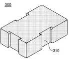
도 5는 본 발명의 일 실시예에 따른 중량체의 사시도이다.
도 6은 본 발명의 일 실시예에 따른 중량체와 진동부재가 결합한 모습을 도시한 평면도이다.
도 7은 본 발명의 다른 실시예에 따른 진동 발생장치의 분해 사시도이다.
도 8은 본 발명의 다른 실시예에 따른 진동 부재의 사시도이다.1 is an exploded perspective view of a vibration generator according to an embodiment of the present invention.
2 is an assembled cross-sectional view of a vibration generator according to an embodiment of the present invention.
FIG. 3A is a perspective view of a vibration member according to an embodiment of the present invention, and FIG. 3B is a bottom perspective view of a vibration member according to an embodiment of the present invention.
4 is a cross-sectional view taken along line A-A 'in Fig.
5 is a perspective view of a weight according to an embodiment of the present invention.
6 is a plan view showing a state where a weight body and an oscillating member are combined according to an embodiment of the present invention.
7 is an exploded perspective view of a vibration generator according to another embodiment of the present invention.
8 is a perspective view of a vibration member according to another embodiment of the present invention.
본 발명의 상세한 설명에 앞서, 이하에서 설명되는 본 명세서 및 청구범위에 사용된 용어나 단어는 통상적이거나 사전적인 의미로 한정해서 해석되어서는 아니 되며, 발명자는 그 자신의 발명을 가장 최선의 방법으로 설명하기 위해 용어의 개념으로 적절하게 정의할 수 있다는 원칙에 입각하여 본 발명의 기술적 사상에 부합하는 의미와 개념으로 해석되어야만 한다. 따라서 본 명세서에 기재된 실시예와 도면에 도시된 구성은 본 발명의 가장 바람직한 실시예에 불과할 뿐, 본 발명의 기술적 사상을 모두 대변하는 것은 아니므로, 본 출원시점에 있어서 이들을 대체할 수 있는 다양한 균등물과 변형 예들이 있을 수 있음을 이해하여야 한다.
Prior to the detailed description of the present invention, the terms or words used in the present specification and claims should not be construed as limited to ordinary or dictionary meanings, and the inventor may designate his own invention in the best way It should be construed in accordance with the technical idea of the present invention based on the principle that it can be appropriately defined as a concept of a term to describe it. Therefore, the embodiments described in the present specification and the configurations shown in the drawings are merely the most preferred embodiments of the present invention, and are not intended to represent all of the technical ideas of the present invention. Therefore, various equivalents It should be understood that water and variations may be present.
이하, 첨부된 도면을 참조하여 본 발명의 바람직한 실시예들을 상세히 설명한다. 이때, 첨부된 도면에서 동일한 구성 요소는 가능한 동일한 부호로 나타내고 있음을 유의해야 한다. 또한, 본 발명의 요지를 흐리게 할 수 있는 공지 기능 및 구성에 대한 상세한 설명은 생략할 것이다. 마찬가지의 이유로 첨부 도면에 있어서 일부 구성요소는 과장되거나 생략되거나 또는 개략적으로 도시되었으며, 각 구성요소의 크기는 실제 크기를 전적으로 반영하는 것이 아니다.
Hereinafter, preferred embodiments of the present invention will be described in detail with reference to the accompanying drawings. Note that, in the drawings, the same components are denoted by the same reference symbols as possible. Further, the detailed description of known functions and configurations that may obscure the gist of the present invention will be omitted. For the same reason, some of the elements in the accompanying drawings are exaggerated, omitted, or schematically shown, and the size of each element does not entirely reflect the actual size.
도 1은 본 발명의 일 실시예에 따른 진동 발생장치(10)의 분해사시도이고, 도 2는 본 발명의 일 실시예에 따른 진동 발생장치(10)의 결합 단면도이다.
FIG. 1 is an exploded perspective view of a vibration generating
도 1 및 도 2를 참조하면, 본 발명의 일 실시예에 따른 진동 발생장치(10)는 하우징(100), 진동부재(200), 중량체(300) 및 압전소자(400)를 포함한다.
1 and 2, a
하우징(100)은 진동 발생장치(10)의 외관을 형성하는 부재로서, 상부 케이스(110)와 상기 상부 케이스(110)에 결합되어 내부공간을 형성하는 하부 케이스(120)를 포함하며,상기 내부공간에는 후술할 진동부재(200), 중량체(300) 및 압전소자(400)가 구비된다.The
이때, 상부 케이스(110)와 하부 케이스(120)는 용접, 접착제를 이용한 본딩, 후크 결합 등의 다양한 방법으로 결합될 수 있다.
At this time, the
하부 케이스(120)에는 진동부재(200)가 진동할 수 있는 공간을 확보해주는 지지부재(121)가 구비될 수 있으며, 지지부재(121)는 하부 케이스(120)의 일측에서 상기 내부공간으로 돌출 구비될 수 있다.The
지지부재(121)는 하부 케이스(120)의 일측을 절곡하여 제작되거나, 하부 케이스(120)의 제작 시 동시에 제작될 수 있다.The
물론, 지지부재(121)는 하부 케이스(120)를 절곡하여 형성될 수 있을 뿐만 아니라, 하부 케이스(120)에 별도의 서포트 부재(미도시)를 결합시켜 구비될 수 있으며, 결합 방법으로는 용접, 접착제를 이용한 본딩 등 다양한 방법이 사용될 수 있다.Of course, the
지지부재(121)에는 진동부재(200)의 일단이 고정될 수 있으며, 진동부재(200)는 지지부재(121)에 일단이 고정된 상태에서 진동하게 된다. 즉, 상기 진동부재(200)는 기본적으로 캔틸레버(Cantilever, 외팔보)방식으로 구비되어, 자유단부가 진동할 수 있다.One end of the
하부 케이스(120)에서 돌출 구비되는 지지부재(121)에 의해 진동부재(200)와 하부 케이스(120) 사이에는 진동부재(200)가 진동할 수 있는 공간, 다시 말해 에어 갭(G)이 구비된다.
A space in which the
상부 케이스(110)에는 진동 발생장치(10)의 제조 후 상기 진동 발생장치(10)의 공진 주파수를 조정할 수 있도록 주파수 조정홀(111)이 구비된다.The
주파수 조정홀(111)은 상부 케이스(110)의 중량체(300)와 대향하는 일측이 개방되어 구비될 수 있으며, 진동부재(200)의 고정단 쪽으로 치우치게 구비될 수 있다.The
따라서, 제작자는 진동 발생장치(10)를 제작한 후에도 상기 주파수 조정홀(111)을 통해 중량체(300)에 추가 중량 부재(20)를 결합시킬 수 있다.Therefore, the manufacturer can attach the
즉, 진동 발생장치(10)의 공진 주파수는 중량체(300)의 질량에 의해서 가변되므로, 제작자는 추가 중량 부재(20)의 질량을 조절하여 원하는 공진 주파수를 설정할 수 있다.That is, since the resonance frequency of the
결과적으로 본 발명의 일 실시예에 따른 진동 발생장치(10)는 하우징(100)의 일측에 주파수 조정홀(111)을 구비하여 진동 발생장치(10) 제작 후에도 중량체(300)의 전체 질량을 조정하여 진동 발생장치(10)의 공진 주파수를 조정할 수 있다.
As a result, the
한편, 하우징(100)에는 진동부재(200)와의 충돌을 방지하고 진동부재(200)의 변위를 조절하는 스토퍼(130)가 구비될 수 있으며, 이때 스토퍼(130)는 진동 발생장치(10)의 구동 시 진동부재(200)와 접촉할 수 있다.
The
즉, 진동 발생장치(10)가 구동하는 경우 진동부재(200)는 하우징(100) 내부에서 진동하게 되므로, 하우징(100)의 내면과 충돌할 수 있으며, 진동 부재(200)가 하우징(100)에 충돌하는 경우, 진동부재(200)가 파손될 우려가 있다.That is, when the
따라서, 하우징(100)에 스토퍼(130)를 구비함으로써, 진동부재(200)와 하우징(100)의 충돌을 방지할 수 있으며, 이에 더하여, 진동부재(200)가 하측으로 진동가능한 변위를 조절할 수 있다.
Therefore, by providing the
도 3a는 본 발명의 일 실시예에 따른 진동부재(200)의 사시도이고, 도 3b는 본 발명의 일 실시예에 따른 진동부재(200)의 저면 사시도이고, 도 4는 도 3a의 A-A'에 따른 단면도이다.
3A is a perspective view of a
도 3 및 도 4를 참조하면, 진동부재(200)는 하우징(100)의 내부공간에 일단이 고정되고 타단이 진동가능하도록 구비된다.3 and 4, the
즉, 진동 부재(200)는 하우징(100)에 일단이 고정되고 타단은 자유단인 제1 부재(210), 상기 제1 부재(210)의 타단에서 제1 부재(210)의 상면 방향으로 연장구비되는 제2 부재(220) 및 상기 제2 부재(220)의 단부에서 상기 제1 부재(210)의 일단 쪽으로 연장 구비도는 제3 부재(230)를 구비하며, 제1 내지 제3부재(210, 220, 230)에는 진동부재(200)간의 충돌을 방지하기 위한 적어도 하나의 댐퍼(240)가 구비될 수 있다.
That is, the vibrating
여기서 방향에 대한 용어를 정의하면, 부재의 상면이라 함은 상기 부재의 상기 상부 케이스(110)와 대향하는 일면을 의미하며, 부재의 하면이라 함은 상기 부재의 상기 하부 케이스(120)와 대향하는 일면을 의미한다.
Here, the term 'upper surface' refers to one surface of the member facing the
제1 부재(210)는 지지부재(121)에 일단이 고정될 수 있다. 즉, 제1 부재(210)의 일단은 지지부재(121)에 고정된 고정단(216)이고, 타단은 자유단(217)일 수 있다(도 2참조).The
이때, 제1 부재(210)는 지지부재(121)에 용접 또는 접착제를 이용한 본딩, 스크루 결합 등의 방법으로 고정될 수 있다.At this time, the
제1 부재(210)와 하부 케이스(120) 사이에는 에어갭(G)이 구비될 수 있다.
An air gap G may be provided between the
한편, 제1 부재(210)에는 전기적 신호에 의해 진동부재(200)를 가진 시키는 압전소자(400)가 적어도 하나 구비될 수 있다.The
여기서 상기 압전소자(400)는 폴리머 재질 또는 티탄산 지르콘산연(타이타늄산 지르콘산 연) [PZT, lead zirconate titanate] 재질일 수 있다.Here, the
다만, 반드시 이에 한정되는 것은 아니며, 진동부재(200)를 가진시킬 수 있는 다양한 재질의 압전소자가 사용될 수 있다.
However, the present invention is not limited thereto, and a piezoelectric element having various materials capable of vibrating the vibrating
또한, 제1 부재(210)의 일면에는 압전소자(400)가 안착되어 결합할 수 있는 결합홈(211)이 구비될 수 있으며, 결합홈(211)은 압전소자(400)의 외형에 대응되게 제1 부재(210)의 일면에서 인입되어 구비될 수 있다.The
즉, 압전소자(400)는 결합홈(211)에 안착되어 결합함으로써, 보다 견고하게 제1 부재(210)와 결합할 수 있다.
In other words, the
제2 부재(220)는 제1 부재(210)의 타단에서 제1 부재(210)의 상면 방향으로 복수회 절곡되어 연장 구비될 수 있으며, 이때 제1 부재(210)와 제2 부재(220)가 연결되는 부분에는 곡률(R)이 형성될 수 있다.The
여기서, 식 1 및 식 2를 참조하여 본 발명의 일 실시예에 따른 진동 발생장치(10)가 공진 주파수를 유지하면서, 크기를 감소시키는 원리를 간략히 설명한다.
Here, the principle of reducing the size while maintaining the resonance frequency of the


상기 식 1 및 식 2에서, 'K'는 비례상수를 의미하고, 'L'은 진동부재의 길이를 의미하고, 'm'은 진동 부재의 질량을 의미하며, 'ω'는 공진 주파수를 의미한다.
In Equation 1 and Equation 2, 'K' denotes a proportional constant, 'L' denotes a length of the vibration member, 'm' denotes a mass of the vibration member, and 'ω' denotes a resonance frequency do.
식 1 및 식 2를 참조하면, 공진 주파수는 진동부재의 길이가 짧아질수록 증가하고, 진동부재의 길이가 길어질수록 감소한다.Referring to Equations 1 and 2, the resonance frequency increases as the length of the vibration member becomes shorter, and decreases as the length of the vibration member becomes longer.
따라서, 진동 발생장치의 소형화를 위해, 진동부재의 길이를 감소시키면 공진 주파수가 증가해 진동 발생장치로서 기능을 하기 어려워진다.Therefore, in order to reduce the size of the vibration generator, if the length of the vibration member is reduced, the resonance frequency increases, making it difficult to function as the vibration generator.
다만, 본 발명의 일 실시예에 따른 진동 발생장치(10)는, 진동부재(200)를 절곡시켜 구비함으로써 진동부재(200)의 전체 길이는 유지하면서도 진동 발생장치(10)의 전체적인 크기를 감소시킬 수 있다.
However, the
한편, 제2 부재(220)는 제1 부재(210)의 타단에서 수직으로 연장 구비되어 적어도 4회가 절곡될 수 있으며, 이하에서는 제2 부재(220)가 4회 절곡된 구성을 예로 들어 설명한다.The
제2 부재(220)는 제1 부재(210)의 상면 방향으로 연장구비되는 제1 절곡부(221), 상기 제1 절곡부(221)의 단부에서 상기 제1 부재(210)의 일단 쪽으로 연장 구비되는 제2 절곡부(222), 상기 제2 절곡부(222)의 단부에서 상기 제2 절곡부(222)의 상면 방향으로 연장구비되는 제3 절곡부(223), 상기 제3 절곡부(223)의 단부에서 상기 제1 부재(210)의 타단쪽으로 연장구비되는 제4 절곡부(224) 및 상기 제4 절곡부(224)의 단부에서 상기 제4 절곡부(224)의 상면 방향으로 연장구비되는 제5 절곡부(225)로 구비된다.
The
이때, 상기 제1 내지 제5 절곡부(221, 222, 223, 224, 225)의 연결부분에는 곡률(R)이 형성될 수 있으며, 제2 절곡부(222)와 제4 절곡부(224)는 나란하게 구비될 수 있다.At this time, a curvature R may be formed at a connecting portion of the first to
또한, 제2 절곡부(222)는 상기 제2 절곡부(222)와 대향하는 제1 부재(210)와 나란하게 구비될 수 있으며, 제4 절곡부(224)는 상기 제4 절곡부(224)와 대향하는 제3부재(230)와 나란하게 구비될 수 있다.The
또한, 상기 제1 내지 제5 절곡부(221, 222, 223, 224, 225)에는 진동 발생장치(10)의 구동 시 충돌을 방지하기 위한 댐퍼(240)가 구비될 수 있다.
The
제3 부재(230)는 제2 부재(220)의 단부에서 제1 부재(210)의 일단쪽으로 연장되어 구비될 수 있으며, 제2 부재(220)와 제3 부재(230)가 연결되는 부분에는 곡륙(R)이 형성될 수 있다.The
또한, 제3 부재(230)는 제2 부재(200)의 단부에서 수직으로 연장되어 구비될 수 있다.In addition, the
나아가, 제 3부재(230)에는 절국 구비되어 중량체(300)가 결합하는 중량체 결합부(231)가 구비될 수 있다.Further, the
또한, 중량체 결합부(231)의 외측면에는 돌출 절곡되어 중량체(300)를 지지하는 결합돌기(232)가 구비될 수 있다.In addition, the outer surface of the
후술하겠지만, 중량체(300)의 상기 결합돌기(232)와 대면하는 외측면에는 결합돌기(232)가 삽입될 수 있는 삽입홈(310)이 구비될 수 있으며, 상기 결합돌기(232)는 삽입홈(310)에 삽입되어 결합할 수 있다.As will be described later, the outer surface of the
또한, 중량체 결합부(231)와 중량체(400)는 용접 또는 접착제를 이용한 본딩에 의해 결합될 수 있으며, 결합돌기(232)와 삽입홈(310)의 기계적 결합으로만 결합시키는 것도 가능하다.The
또한, 지지부재(121)의 상측에는 제3 부재(230)의 일부분이 겹치도록 배치될 수 있다.
In addition, a part of the
진동부재(200)에는 탄성 변형이 용이하도록 진동부재(200)의 강도를 저감시키기위한 적어도 하나의 탄성변형 보조홀(250)이 구비될 수 있다.The
즉, 상기 탄성변형 보조홀(250)은 상기 진동부재(200)의 강도를 저감시킴으로써 진동 발생장치(10)의 구동 시 진동부재(200)의 탄성변형을 용이하게 할 수 있다.
That is, the elastic
한편, 진동부재(200)의 형상은 변경가능하며, 이하에서는 진동부재(200)의 변형예에 대해 설명한다.
On the other hand, the shape of the
도 7은 본 발명의 다른 실시예에 따른 진동발생장치(10)의 분해 사시도이고, 도 8은 본 발명의 다른 실시예에 따른 진동부재의 사시도이다.
FIG. 7 is an exploded perspective view of a
도 7 및 도 8에 도시된 진동부재(200)는 제3 부재의 구성을 제외하고 다른 구성은 도 3 및 도 4에 개시된 진동부재와 실질적으로 동일하다.The
따라서, 동일한 구성에 대한 상세한 설명은 생략하고 상기한 설명에 갈음 하기로 한다.
Therefore, detailed description of the same configuration will be omitted and the above description will be omitted.
본 발명의 다른 실시예에서 진동부재(230)는 하우징(100)에 일단이 고정되고 타단은 자유단인 제1 부재(210), 상기 제1 부재(210)의 타단에서 상기 제1 부재(210)의 상면 방향으로 연장 구비되는 제2 부재(220) 및 상기 제2 부재(220)의 단부에서 상기 제1 부재(210)의 일단 쪽으로 연장 구비되는 제3 부재(230)를 구비한다.
In another embodiment of the present invention, the
여기서 제3 부재(230)의 테두리에는 제1 부재(210)가 구비된 방향으로 연장 절곡된 결합돌기(232)가 구비된다.Here, the
결합돌기(232)는 제3 부재의 저면에 안착되어 결합하는 중량체(300)의 중량체 삽입홈(310)에 삽입된 상태로 중량체(300)를 지지할 수 있다.
The engaging
또한, 제3 부재(230)의 제2 부재(220)와 연결된 일측에는 탄성 변형 보조슬릿(250)이 구비될 수 있다.In addition, the elastic deformation
탄성 보조슬릿(250')은 진동부재(200)의 강도를 저감시킴으로써, 진동 발생장치(10)의 구동시 진동부재(200)의 탄성 변형을 용이하게 할 수 있다.
The elastic auxiliary slit 250 'can facilitate the elastic deformation of the
도 5는 본 발명의 일 실시예에 따른 중량체의 사시도이고, 도 6은 본 발명의 일 실시예에 따른 중량체와 진동부재가 결합한 모습을 도시한 평면도이다.
FIG. 5 is a perspective view of a weight according to an embodiment of the present invention, and FIG. 6 is a plan view showing a combination of a weight and an oscillating member according to an embodiment of the present invention.
도 5 및 도 6을 참조하면, 중량체(300)는 진동부재(200)의 진동 시 연동되어 진동하여 진동부재(300)의 진동량을 증대시키는 역할을 하며 진동부재(200)의 일측에 구비된다.Referring to FIGS. 5 and 6, the
여기서, 중량체(300)는 진동부재(200)의 다양한 위치에 구비될 수 있으나, 이하에서는 중량체(300)가 진동부재(200)의 제3 부재(230)에 구비된 구성을 예로 들어 설명한다.Here, the
중량체(300)는 제3 부재(230)의 중량체 결합부(231)에 결합되며, 용접, 접착제를 이용한 본딩 또는 기계적 결합으로 결합될 수 있다.The
중량체(300)의 외측면에는 전술한 바와 같이 삽입홈(310)이 구비될 수 있으며, 삽입홈(310)에는 제3 부재(230)에 구비되는 결합돌기(232)가 삽입된다.The outer surface of the
따라서 중량체(300)는 제3 부재에 보다 안정적으로 고정될 수 있다.Therefore, the
또한, 중량체(300)에는 하우징(100)과의 충돌을 방지하기 위한 댐퍼가 구비될 수 있다.
In addition, the
한편, 진동 발생장치(10)에서 중량체(300)는 진동 발생장치(10)의 공진 주파수를 결정하는 중요한 요소에 해당한다.On the other hand, in the
따라서, 본 발명의 실시예에 따른 진동 발생장치(10)에서는 진동 발생장치(10)의 제작 후 추가 중량부재(20)를 중량체(300)에 결합시킴으로써 진동 발생장치(10)의 공진 주파수를 조정할 수 있는 효과가 있다.
Therefore, in the
다시, 도 2를 참조하면, 압전소자(400)는 전기적 신호에 의해 휨변형을 일으켜 진동부재(200)를 가진시키는 역할을 수행하는 것으로 제1 부재(210)의 하우징(100)과 대면하는 일면 또는 반대면인 타면에 구비된다.Referring to FIG. 2, the
다만, 상기 압전소자(400)가 구비되는 위치 및 개수는 다양하게 변경가능하다. 즉, 압전소자는 제1 부재 내지 제3 부재 중 적어도 하나에 구비될 수도 있다.However, the position and the number of the
이때, 압전소자(400)의 상측에는 중량체(300)의 적어도 일부가 위치할 수 있으며, 압전소자(400)의 중심은 제1 부재(210)의 자유단(217)쪽으로 치우치게 구비될 수 있다.At this time, at least a part of the
압전소자(400)는 폴리머 재질 또는 티탄산 지르콘산 연(타이타늄산 지르콘산 연) [PZT, lead zirconate titanate] 재질 일 수 있으며, 이에 한정되는 것은 아니고, 상기 진동부재(200)에 진동을 발생시킬 수 있는 다양한 재질의 압전소자가 사용될 수 있다.
The
한편, 제1 부재(210)에는 압전소자(400)가 안착되어 결합하는 결합홈(211)이 구비될 수 있으며, 상기 결합홈(211)은 압전소자(400)의 외형에 대응되게 제1 부재(210)의 일측에서 인입되어 구비될 수 있다.
The
상기에서는 본 발명에 따른 실시예를 기준으로 본 발명의 구성과 특징을 설명하였으나 본 발명은 이에 한정되지 않으며, 본 발명의 사상과 범위 내에서 다양하게 변경 또는 변형할 수 있음은 본 발명의 속하는 기술분야의 통상의 기술자들에게 명백한 것이며, 따라서 이와 같은 변경 또는 변형은 첨부된 특허청구범위에 속함을 밝혀둔다.
While the present invention has been described with reference to exemplary embodiments, it is to be understood that the invention is not limited to the disclosed exemplary embodiments, but, on the contrary, It will be apparent to those of ordinary skill in the art that such changes or modifications are within the scope of the appended claims.
100:하우징110: 상부 케이스
111: 주파수 조정홀120: 하부케이스
130: 스토퍼200: 진동부재
210: 제1 부재220: 제2 부재
230: 제3 부재300: 중량체
400: 압전소자100: housing 110: upper case
111: Frequency adjusting hole 120: Lower case
130: stopper 200: vibration member
210: first member 220: second member
230: third member 300: weight member
400: piezoelectric element
Claims (10)
Translated fromKorean상기 하우징에 일단이 고정된 고정단 및 상기 고정단에서 연장 형성되어 진동가능하게 구비되는 자유단을 포함하는 제1 부재, 상기 제1 부재의 자유단에서 상기 제1 부재의 상면 방향으로 연장 구비되는 제2 부재 및 상기 제2 부재의 단부에서 상기 제1 부재의 일단 쪽으로 연장 구비되는 제3 부재를 포함하며, 상기 제1 부재 내지 제3 부재에는 충돌을 방지하기 위해 적어도 하나 이상의 댐퍼가 마련되는 진동부재;
상기 진동부재에 구비되는 중량체; 및
상기 진동부재의 일면에 결합되는 압전소자;
를 포함하며,
상기 주파수 조정홀은 상기 중량체와 대향하는 상기 하우징의 일측이 상기 진동부재의 고정단쪽으로 치우치게 개방되어 구비되고,
상기 진동부재에는 상기 진동 부재의 강도를 조절할 수 있도록 적어도 하나의 탄성변형 보조홀이 구비되는 진동 발생장치.
A housing including a stopper which is opened at one side to form a frequency adjusting hole and prevents a collision between the oscillating member and the housing;
A first member including a fixed end whose one end is fixed to the housing and a free end which is extended from the fixed end and is freely oscillatable, and a second member extending from the free end of the first member in the direction of the top surface of the first member And a third member extending from the end of the second member to the one end of the first member, wherein the first member to the third member are provided with at least one damper for preventing collision, absence;
A weight provided on the vibration member; And
A piezoelectric element coupled to one surface of the vibration member;
/ RTI >
Wherein the frequency adjusting hole is provided so that one side of the housing facing the weight body is biased open toward the fixed end of the oscillating member,
Wherein the vibration member is provided with at least one elastic deformation supporting hole so as to adjust the strength of the vibration member.
상기 제2 부재는 적어도 4회가 절곡되어 구비되는 진동 발생장치.
The method according to claim 1,
And the second member is bent at least four times.
상기 제2 부재는 제1 부재의 상면 방향으로 수직하게 연장구비되고, 상기 제3 부재는 상기 제2 부재의 단부에서 수직으로 연장구비되는 진동 발생장치.
The method according to claim 1,
Wherein the second member extends perpendicularly to the top surface direction of the first member and the third member extends vertically at the end of the second member.
상기 제3 부재에는 절곡 구비되어 상기 중량체가 결합하는 중량체 결합부가 구비되는 진동 발생장치.
The method according to claim 1,
And the third member is provided with a weight coupling portion that is bent to be coupled with the weight.
상기 진동부재의 일면에는 상기 압전소자가 안착되어 결합할 수 있도록 함입되어 형성된 결합홈이 구비되는 진동 발생장치.
The method according to claim 1,
And a coupling groove formed on one surface of the vibration member so as to allow the piezoelectric element to be seated and coupled therewith.
Priority Applications (2)
| Application Number | Priority Date | Filing Date | Title |
|---|---|---|---|
| KR1020140124275AKR101652301B1 (en) | 2014-09-18 | 2014-09-18 | Vibrator |
| US14/643,315US20160082476A1 (en) | 2014-09-18 | 2015-03-10 | Vibration generating device |
Applications Claiming Priority (1)
| Application Number | Priority Date | Filing Date | Title |
|---|---|---|---|
| KR1020140124275AKR101652301B1 (en) | 2014-09-18 | 2014-09-18 | Vibrator |
Publications (2)
| Publication Number | Publication Date |
|---|---|
| KR20160033430A KR20160033430A (en) | 2016-03-28 |
| KR101652301B1true KR101652301B1 (en) | 2016-08-30 |
Family
ID=55524866
Family Applications (1)
| Application Number | Title | Priority Date | Filing Date |
|---|---|---|---|
| KR1020140124275AExpired - Fee RelatedKR101652301B1 (en) | 2014-09-18 | 2014-09-18 | Vibrator |
Country Status (2)
| Country | Link |
|---|---|
| US (1) | US20160082476A1 (en) |
| KR (1) | KR101652301B1 (en) |
Citations (1)
| Publication number | Priority date | Publication date | Assignee | Title |
|---|---|---|---|---|
| KR100215989B1 (en)* | 1994-11-07 | 1999-08-16 | 모리시타 요이찌 | Piezoelectric actuator and pyroelectric infrared sensor using it |
Family Cites Families (12)
| Publication number | Priority date | Publication date | Assignee | Title |
|---|---|---|---|---|
| US6960870B2 (en)* | 1997-07-29 | 2005-11-01 | Seiko Epson Corporation | Piezo-electric resonator and manufacturing method thereof |
| JPH11145764A (en)* | 1997-11-11 | 1999-05-28 | Murata Mfg Co Ltd | Piezoelectric resonance part and its frequency control method |
| JP3972790B2 (en)* | 2001-11-27 | 2007-09-05 | 松下電器産業株式会社 | Thin film micromechanical resonator and thin film micromechanical resonator gyro |
| US7859172B2 (en)* | 2007-06-19 | 2010-12-28 | Epson Toyocom Corporation | Piezoelectric resonator, manufacturing method thereof and lid for piezoelectric resonator |
| JP4851549B2 (en)* | 2009-02-10 | 2012-01-11 | 日本電波工業株式会社 | Piezoelectric device |
| WO2013051400A1 (en)* | 2011-10-03 | 2013-04-11 | 株式会社村田製作所 | Ultrasonic-wave generation device |
| KR101316782B1 (en)* | 2011-10-06 | 2013-10-11 | 주식회사 하이소닉 | Vibrator mounted piezoelectric element |
| KR101512286B1 (en)* | 2013-01-29 | 2015-04-15 | 한국과학기술연구원 | Energy harvester |
| US9431926B2 (en)* | 2013-05-23 | 2016-08-30 | Mplus Co., Ltd. | Vibration generating apparatus and electronic apparatus including the same |
| KR101662126B1 (en)* | 2014-05-02 | 2016-10-05 | 주식회사 엠플러스 | Vibrator |
| KR101685962B1 (en)* | 2014-05-14 | 2016-12-13 | 주식회사 엠플러스 | Vibrator |
| KR101640443B1 (en)* | 2014-09-18 | 2016-07-18 | 주식회사 엠플러스 | Vibrator |
- 2014
- 2014-09-18KRKR1020140124275Apatent/KR101652301B1/ennot_activeExpired - Fee Related
- 2015
- 2015-03-10USUS14/643,315patent/US20160082476A1/ennot_activeAbandoned
Patent Citations (1)
| Publication number | Priority date | Publication date | Assignee | Title |
|---|---|---|---|---|
| KR100215989B1 (en)* | 1994-11-07 | 1999-08-16 | 모리시타 요이찌 | Piezoelectric actuator and pyroelectric infrared sensor using it |
Also Published As
| Publication number | Publication date |
|---|---|
| KR20160033430A (en) | 2016-03-28 |
| US20160082476A1 (en) | 2016-03-24 |
Similar Documents
| Publication | Publication Date | Title |
|---|---|---|
| KR101685962B1 (en) | Vibrator | |
| JP5409925B2 (en) | Piezoelectric vibration device and portable terminal using the same | |
| JP6052475B2 (en) | Fluid control device | |
| TWI571134B (en) | Apparatus for generating sound | |
| US20170257706A1 (en) | Sound generating unit and electronic device | |
| US10834508B2 (en) | Reinforced actuators for distributed mode loudspeakers | |
| JP6247556B2 (en) | Piezoelectric vibration unit and piezoelectric speaker | |
| KR101652301B1 (en) | Vibrator | |
| KR101544834B1 (en) | piezo-electric vibrator | |
| JP6323562B2 (en) | Drive apparatus and drive method for piezoelectric vibration device | |
| CN104094612B (en) | Acoustic generator, acoustic generating device and electronic equipment | |
| KR101660824B1 (en) | Vibrator | |
| KR101698424B1 (en) | Vibrator | |
| KR101660809B1 (en) | Vibrator | |
| JP6020465B2 (en) | Oscillator | |
| KR101640443B1 (en) | Vibrator | |
| KR20160069858A (en) | Vibrator and electronic device including the same | |
| JP2019220911A (en) | Ultrasonic sensor | |
| JP6153408B2 (en) | Excitation device | |
| KR20180017542A (en) | Piezo Actuator | |
| KR20150114685A (en) | Piezo Actuator | |
| KR101568773B1 (en) | piezo-electric vibrator | |
| KR20140139216A (en) | Piezoelectric vibration module and vibrator including thereof |
Legal Events
| Date | Code | Title | Description |
|---|---|---|---|
| A201 | Request for examination | ||
| PA0109 | Patent application | St.27 status event code:A-0-1-A10-A12-nap-PA0109 | |
| PA0201 | Request for examination | St.27 status event code:A-1-2-D10-D11-exm-PA0201 | |
| D13-X000 | Search requested | St.27 status event code:A-1-2-D10-D13-srh-X000 | |
| D14-X000 | Search report completed | St.27 status event code:A-1-2-D10-D14-srh-X000 | |
| PN2301 | Change of applicant | St.27 status event code:A-3-3-R10-R11-asn-PN2301 | |
| R19-X000 | Request for party data change rejected | St.27 status event code:A-3-3-R10-R19-oth-X000 | |
| N231 | Notification of change of applicant | ||
| PN2301 | Change of applicant | St.27 status event code:A-3-3-R10-R13-asn-PN2301 St.27 status event code:A-3-3-R10-R11-asn-PN2301 | |
| E902 | Notification of reason for refusal | ||
| PE0902 | Notice of grounds for rejection | St.27 status event code:A-1-2-D10-D21-exm-PE0902 | |
| PG1501 | Laying open of application | St.27 status event code:A-1-1-Q10-Q12-nap-PG1501 | |
| P22-X000 | Classification modified | St.27 status event code:A-2-2-P10-P22-nap-X000 | |
| E13-X000 | Pre-grant limitation requested | St.27 status event code:A-2-3-E10-E13-lim-X000 | |
| P11-X000 | Amendment of application requested | St.27 status event code:A-2-2-P10-P11-nap-X000 | |
| P13-X000 | Application amended | St.27 status event code:A-2-2-P10-P13-nap-X000 | |
| E701 | Decision to grant or registration of patent right | ||
| PE0701 | Decision of registration | St.27 status event code:A-1-2-D10-D22-exm-PE0701 | |
| GRNT | Written decision to grant | ||
| PR0701 | Registration of establishment | St.27 status event code:A-2-4-F10-F11-exm-PR0701 | |
| PR1002 | Payment of registration fee | St.27 status event code:A-2-2-U10-U11-oth-PR1002 Fee payment year number:1 | |
| PG1601 | Publication of registration | St.27 status event code:A-4-4-Q10-Q13-nap-PG1601 | |
| PC1903 | Unpaid annual fee | St.27 status event code:A-4-4-U10-U13-oth-PC1903 Not in force date:20190825 Payment event data comment text:Termination Category : DEFAULT_OF_REGISTRATION_FEE | |
| PC1903 | Unpaid annual fee | St.27 status event code:N-4-6-H10-H13-oth-PC1903 Ip right cessation event data comment text:Termination Category : DEFAULT_OF_REGISTRATION_FEE Not in force date:20190825 | |
| R18-X000 | Changes to party contact information recorded | St.27 status event code:A-5-5-R10-R18-oth-X000 |