KR101651806B1 - Inductive power supply system with multiple coil primary - Google Patents
Inductive power supply system with multiple coil primaryDownload PDFInfo
- Publication number
- KR101651806B1 KR101651806B1KR1020167002667AKR20167002667AKR101651806B1KR 101651806 B1KR101651806 B1KR 101651806B1KR 1020167002667 AKR1020167002667 AKR 1020167002667AKR 20167002667 AKR20167002667 AKR 20167002667AKR 101651806 B1KR101651806 B1KR 101651806B1
- Authority
- KR
- South Korea
- Prior art keywords
- power
- segments
- parallel
- coil
- remote device
- Prior art date
- Legal status (The legal status is an assumption and is not a legal conclusion. Google has not performed a legal analysis and makes no representation as to the accuracy of the status listed.)
- Active
Links
Images


Classifications
- H—ELECTRICITY
- H04—ELECTRIC COMMUNICATION TECHNIQUE
- H04B—TRANSMISSION
- H04B5/00—Near-field transmission systems, e.g. inductive or capacitive transmission systems
- H04B5/70—Near-field transmission systems, e.g. inductive or capacitive transmission systems specially adapted for specific purposes
- H04B5/79—Near-field transmission systems, e.g. inductive or capacitive transmission systems specially adapted for specific purposes for data transfer in combination with power transfer
- H—ELECTRICITY
- H02—GENERATION; CONVERSION OR DISTRIBUTION OF ELECTRIC POWER
- H02J—CIRCUIT ARRANGEMENTS OR SYSTEMS FOR SUPPLYING OR DISTRIBUTING ELECTRIC POWER; SYSTEMS FOR STORING ELECTRIC ENERGY
- H02J50/00—Circuit arrangements or systems for wireless supply or distribution of electric power
- H02J50/40—Circuit arrangements or systems for wireless supply or distribution of electric power using two or more transmitting or receiving devices
- H02J17/00—
- H—ELECTRICITY
- H01—ELECTRIC ELEMENTS
- H01F—MAGNETS; INDUCTANCES; TRANSFORMERS; SELECTION OF MATERIALS FOR THEIR MAGNETIC PROPERTIES
- H01F27/00—Details of transformers or inductances, in general
- H01F27/28—Coils; Windings; Conductive connections
- H01F27/2871—Pancake coils
- H—ELECTRICITY
- H01—ELECTRIC ELEMENTS
- H01F—MAGNETS; INDUCTANCES; TRANSFORMERS; SELECTION OF MATERIALS FOR THEIR MAGNETIC PROPERTIES
- H01F38/00—Adaptations of transformers or inductances for specific applications or functions
- H01F38/14—Inductive couplings
- H02J5/005—
- H—ELECTRICITY
- H02—GENERATION; CONVERSION OR DISTRIBUTION OF ELECTRIC POWER
- H02J—CIRCUIT ARRANGEMENTS OR SYSTEMS FOR SUPPLYING OR DISTRIBUTING ELECTRIC POWER; SYSTEMS FOR STORING ELECTRIC ENERGY
- H02J50/00—Circuit arrangements or systems for wireless supply or distribution of electric power
- H02J50/005—Mechanical details of housing or structure aiming to accommodate the power transfer means, e.g. mechanical integration of coils, antennas or transducers into emitting or receiving devices
- H—ELECTRICITY
- H02—GENERATION; CONVERSION OR DISTRIBUTION OF ELECTRIC POWER
- H02J—CIRCUIT ARRANGEMENTS OR SYSTEMS FOR SUPPLYING OR DISTRIBUTING ELECTRIC POWER; SYSTEMS FOR STORING ELECTRIC ENERGY
- H02J50/00—Circuit arrangements or systems for wireless supply or distribution of electric power
- H02J50/10—Circuit arrangements or systems for wireless supply or distribution of electric power using inductive coupling
- H02J50/12—Circuit arrangements or systems for wireless supply or distribution of electric power using inductive coupling of the resonant type
- H—ELECTRICITY
- H02—GENERATION; CONVERSION OR DISTRIBUTION OF ELECTRIC POWER
- H02J—CIRCUIT ARRANGEMENTS OR SYSTEMS FOR SUPPLYING OR DISTRIBUTING ELECTRIC POWER; SYSTEMS FOR STORING ELECTRIC ENERGY
- H02J50/00—Circuit arrangements or systems for wireless supply or distribution of electric power
- H02J50/70—Circuit arrangements or systems for wireless supply or distribution of electric power involving the reduction of electric, magnetic or electromagnetic leakage fields
- H02J7/025—
- H04B5/0037—
- H—ELECTRICITY
- H04—ELECTRIC COMMUNICATION TECHNIQUE
- H04B—TRANSMISSION
- H04B5/00—Near-field transmission systems, e.g. inductive or capacitive transmission systems
- H04B5/20—Near-field transmission systems, e.g. inductive or capacitive transmission systems characterised by the transmission technique; characterised by the transmission medium
- H04B5/24—Inductive coupling
- H04B5/26—Inductive coupling using coils
- H04B5/266—One coil at each side, e.g. with primary and secondary coils
- H—ELECTRICITY
- H04—ELECTRIC COMMUNICATION TECHNIQUE
- H04B—TRANSMISSION
- H04B5/00—Near-field transmission systems, e.g. inductive or capacitive transmission systems
- H04B5/70—Near-field transmission systems, e.g. inductive or capacitive transmission systems specially adapted for specific purposes
- H04B5/77—Near-field transmission systems, e.g. inductive or capacitive transmission systems specially adapted for specific purposes for interrogation
Landscapes
- Engineering & Computer Science (AREA)
- Computer Networks & Wireless Communication (AREA)
- Power Engineering (AREA)
- Signal Processing (AREA)
- Physics & Mathematics (AREA)
- Electromagnetism (AREA)
- Charge And Discharge Circuits For Batteries Or The Like (AREA)
- Secondary Cells (AREA)
- Near-Field Transmission Systems (AREA)
Abstract
Translated fromKoreanDescription
Translated fromKorean본 출원은 2008년 3월 13일자로 출원된 미국 가출원 제61/036,459호의 우선권을 주장한다.This application claims priority to U.S. Provisional Application No. 61 / 036,459, filed March 13, 2008.
본 발명은 유도 결합에 관한 것이고, 더 구체적으로는 복수 범위의 유도 전력을 제공하는 시스템 및 방법에 관한 것이다.The present invention relates to inductive coupling, and more particularly, to a system and method for providing multiple ranges of inductive power.
전자기 유도 원리를 이용하여 무선 전력을 제공하기 위한 시스템은 수년 동안 이용할 수 있었다. 종래의 시스템들은 기존 유도 기술의 현실적인 한계로 인해 제한된 성공을 거두어왔다. 예를 들어, 종래의 유도 시스템들은 타당하게 효율적인 동작을 제공하기 위해, 전형적으로 유도 전력 공급장치 내의 전자 장치와 원격 장치 내의 전자 장치 간의 고도의 조화된 튜닝뿐만 아니라, 1차 코일과 2차 코일 간의 밀접하고 정밀한 정렬을 필요로 한다. 이러한 문제들은 상이한 원격 장치들이 매우 상이한 양의 전력을 필요로 할 수 있다는 사실로 인해 복잡해진다. 예를 들어, 셀폰은 랩탑 또는 주방 가전과는 다른 전력 요건을 가질 가능성이 많다.Systems for providing wireless power using electromagnetic induction principles have been available for many years. Conventional systems have achieved limited success due to the practical limitations of existing induction techniques. For example, in order to provide reasonably efficient operation, conventional induction systems typically require a high degree of coordinated tuning between the electronics in the inductive power supply and the electronics in the remote device, as well as between the primary and secondary coils It requires close and precise alignment. These problems are complicated by the fact that different remote devices may require a very different amount of power. For example, cell phones are likely to have different power requirements than laptops or kitchen appliances.
유도 전력 공급장치가 원격 장치들 간의 몇몇 차이들을 조정하고 책임지게 하는 일부 진전이 있었다. Kuennen 등의 미국 특허 제6,825,620호는 다양한 부하들의 동작 매개변수들에 대응하도록 동작을 조정하는 능력을 갖는 유도 전력 공급 시스템을 개시한다. Kuennen 등의 미국 특허 제6,825,620호는 발명의 명칭이 "Inductively Coupled Ballast Circuit"이고 2004년 11월 30일에 발행되었으며, 여기에 참조에 의해 포함된다. 미국 특허 출원 제11/965,085호는 원격 장치와 그것의 동작 매개변수들을 식별하는 능력을 갖는 유도 전력 공급 시스템을 개시한다. Baarman 등의 미국 특허 출원 제11/965,085호는 발명의 명칭이 "Inductive Power Supply with Device Identification"이고 2007년 12월 27일자로 출원되었으며, 여기에 참조에 의해 포함된다. 이들이 기존 시스템들에 비해 향상을 나타내긴 하지만, 일부 응용들에서는 훨씬 더한 유연성에 대한 바람이 있다. 일부 응용들에서는, 복수 범위의 전력을 제공할 수 있는 단일의 유도 전력 공급장치에 대한 바람이 존재한다.There has been some progress in the inductive power supply to coordinate and account for some of the differences between the remote devices. U. S. Patent No. 6,825, 620 to Kuennen et al. Discloses an inductive power supply system having the ability to adjust operation to correspond to operating parameters of various loads. U. S. Patent No. 6,825, 620 to Kuennen et al. Is entitled " Inductively Coupled Ballast Circuit ", issued November 30, 2004, which is incorporated herein by reference. U.S. Patent Application No. 11 / 965,085 discloses an inductive power supply system having the ability to identify remote devices and their operating parameters. U.S. Patent Application No. 11 / 965,085 to Baarman et al., Entitled Inductive Power Supply with Device Identification, filed December 27, 2007, which is incorporated herein by reference. While these represent improvements over existing systems, there is a desire for greater flexibility in some applications. In some applications, there is a desire for a single inductive power supply that can provide multiple ranges of power.
본 발명은 원격 장치의 전력 등급을 식별하고 그 전력 등급의 함수로서 유도 전력을 제공하는 유도 전력 공급 시스템 및 관련 방법을 제공한다. 전력 등급의 함수로서 전력을 제공하기 위해, 유도 전력 공급장치는 복수의 코일을 갖는 1차 코일 어셈블리를 포함한다. 각각의 코일은 상이한 전력 등급에 관련된 범위의 유도 전력을 생성하기 위해 선택적으로 급전될 수 있다. 유도 전력 공급 시스템은 물리적 전기 접촉없이 원격 장치들에 복수 범위의 전력을 제공한다.The present invention provides an inductive power supply system and associated method for identifying a power rating of a remote device and providing inductive power as a function of the power rating. To provide power as a function of power rating, the inductive power supply includes a primary coil assembly having a plurality of coils. Each coil may be selectively powered to produce an inductive power in the range associated with the different power classes. An inductive power supply system provides multiple ranges of power to remote devices without physical electrical contact.
일 실시예에서, 본 발명은 제어기, 코일 선택기 회로 및 코일 어셈블리를 갖는 유도 전력 공급장치를 포함한다. 본 실시예에서, 코일 어셈블리는 저전력 코일, 중간 전력 코일 및 고전력 코일을 포함한다. 각각의 원격 장치는 저전력 등급, 중간 전력 등급 또는 고전력 등급 장치로 분류된다. 제어기 및 코일 선택기 회로는 선택된 코일에 급전(energizing)하도록 동작한다. 일반적으로, 저전력 코일은 저전력 등급 장치들에 전력을 제공하기 위해 급전되고, 중간 전력 코일은 중간 등급 장치들에 전력을 제공하기 위해 급전되고, 고전력 코일은 고전력 등급 장치들에 전력을 제공하기 위해 급전된다. 일부 응용들에서는, 중간 전력 등급 및 고전력 등급 장치들에서도, 저전력 코일이 인증, 식별 또는 통신을 위해 이용될 수 있다. 유도 전력 공급장치는 선택된 코일에 의해 제공되는 전력을 튜닝하기 위한 기법들을 구현할 수 있다. 예를 들어, 각각의 코일은 적응적일 수 있으며, 그것의 공진 주파수가 조정되게 할 수 있다. 또한, 유도 전력 공급장치의 동작 주파수 또는 다른 동작 특성들은 달라질 수 있다.In one embodiment, the invention includes an inductive power supply having a controller, a coil selector circuit, and a coil assembly. In this embodiment, the coil assembly includes a low power coil, an intermediate power coil, and a high power coil. Each remote device is classified as a low power class, medium power class or high power class device. The controller and coil selector circuit operates to energize the selected coil. Generally, a low power coil is fed to provide power to low power class devices, an intermediate power coil is fed to provide power to intermediate grade devices, a high power coil is fed to provide power to high power class devices, do. In some applications, even intermediate power and high power class devices, a low power coil can be used for authentication, identification or communication. The inductive power supply may implement techniques for tuning the power provided by the selected coil. For example, each coil may be adaptive and its resonant frequency may be adjusted. In addition, the operating frequency or other operating characteristics of the inductive power supply may vary.
동작 시에, 원격 장치는 원격 장치 전력 등급과 같은 전력 수요 정보(power demand information)를 유도 전력 공급장치와 통신할 수 있다. 일 실시예에서, 저전력 코일은 구동 시에 시변 자기장을 생성한다. 2차 회로가 구동된 저전력 코일에 근접하게 이동되면, 2차 회로는 저전력 코일과의 상호 인덕턴스를 형성한다. 저전력 코일의 자기장이 2차 코일을 통과하여 지나가면서 2차 코일에 급전한다. 이것은 세컨더리(secondary)에 전력을 제공하여, 전력 등급 신호가 송신 및 인증되어, 적합한 코일을 선택함으로써 적합한 범위의 전력에서 전력 제어 시퀀스가 시작될 수 있게 해 준다.In operation, the remote device may communicate power demand information, such as a remote device power rating, with the inductive power supply. In one embodiment, the low-power coil produces a time-varying magnetic field upon actuation. When the secondary circuit is moved close to the driven low-power coil, the secondary circuit forms a mutual inductance with the low-power coil. The magnetic field of the low-power coil passes through the secondary coil and feeds the secondary coil. This provides power to the secondary to enable the power rating signal to be transmitted and authenticated, allowing the power control sequence to begin at a suitable range of power by selecting the appropriate coil.
복수의 코일을 갖는 코일 어셈블리를 갖는 유도 전력 공급장치의 한가지 이점은 단일의 핫스폿이 원격 장치에 저전력, 중간 전력 및 고전력을 전달할 수 있다는 것이다. 이것은 저전력 장치에 전력을 공급하는 유도 전력 공급장치, 중간 전력 장치에 전력을 공급하기 위한 별개의 유도 전력 공급장치, 및 고전력 장치에 전력을 공급하기 위한 별개의 유도 전력 공급장치를 가질 필요성을 감소시킨다. 또한, 고전력 장치들이 저전력 소비 기간 동안에는 저전력 코일을 이용할 수 있으므로, 에너지가 절약될 수 있다. 추가로, 공간적 자유를 얻기 위해, 저전력 장치가 고전력 코일로부터 전력을 얻을 수 있다.One advantage of an inductive power supply having a coil assembly with a plurality of coils is that a single hotspot can deliver low power, medium power and high power to the remote device. This reduces the need to have an inductive power supply that powers the low power device, a separate inductive power supply to power the intermediate power device, and a separate inductive power supply to power the high power device . In addition, energy can be saved since high power devices can use low power coils during periods of low power consumption. Additionally, in order to obtain spatial freedom, a low power device can obtain power from a high power coil.
여기에 개시된 것과 그 이외의 본 발명의 목적, 이점 및 특징들은 현재의 실시예의 상세한 설명 및 도면들을 참조하면 쉽게 이해하고 알게 될 것이다.BRIEF DESCRIPTION OF THE DRAWINGS The objects, advantages and features of the invention disclosed herein and others will be readily understood and understood with reference to the detailed description and drawings of the present embodiment.
도 1은 본 발명의 실시예에 따른 유도 전력 공급 시스템의 블록도이다.
도 2는 일 실시예의 1차 회로의 블록도이다.
도 3은 일 실시예의 2차 회로의 블록도이다.
도 4는 일 실시예의 탱크 회로의 개략도이다.
도 5는 일 실시예의 유도 전력 공급 시스템의 개략도이다.
도 6은 일 실시예의 탱크 회로의 개략도이다.
도 7은 일 실시예의 유도 전력 공급 시스템의 개략도이다.
도 8은 일 실시예의 스위칭 회로 및 탱크 회로의 회로도이다.
도 9는 원격 장치에 전력을 공급하기 위한 방법의 일반적인 단계들을 도시하는 흐름도이다.
도 10은 일 실시예의 1차 회로의 기능적 블록도이다.
도 11은 일 실시예의 2차 회로의 기능적 블록도이다.
도 12는 일 실시예의 1차 회로의 기능적 블록도이다.
도 13은 일 실시예의 2차 회로의 기능적 블록도이다.
도 14는 일 실시예의 유도 전력 공급 시스템의 개략도이다.1 is a block diagram of an inductive power supply system according to an embodiment of the present invention.
2 is a block diagram of the primary circuit of one embodiment.
3 is a block diagram of a secondary circuit of one embodiment.
4 is a schematic diagram of the tank circuit of one embodiment.
5 is a schematic diagram of an inductive power supply system of one embodiment.
6 is a schematic diagram of the tank circuit of one embodiment.
7 is a schematic diagram of an inductive power supply system of one embodiment.
8 is a circuit diagram of the switching circuit and the tank circuit of one embodiment.
9 is a flow chart illustrating general steps of a method for powering a remote device.
10 is a functional block diagram of a primary circuit of an embodiment.
11 is a functional block diagram of a secondary circuit of an embodiment.
12 is a functional block diagram of the primary circuit of one embodiment.
13 is a functional block diagram of a secondary circuit of an embodiment.
14 is a schematic diagram of an inductive power supply system of one embodiment.
Ⅰ. 개요Ⅰ. summary
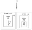
도 1에 도시되고 100으로 지정된 본 발명의 유도 전력 공급 시스템의 실시예에서, 유도 전력 공급 시스템은 유도 전력 공급장치(102) 및 원격 장치(104)를 포함한다. 유도 전력 공급 장치는 복수 범위의 전력을 발생시킬 수 있는 1차 코일 어셈블리(101)를 갖는 1차 회로(103)를 포함한다. 원격 장치(104)는 부하(106)를 갖는 2차 회로(105)를 포함한다. 원격 장치의 2차 회로(105)는 전력 등급을 포함할 수 있는 전력 수요 정보를 포함한다. 적합한 전력 범위에서의 전력 전송을 용이하게 하기 위해, 전력 수요 정보가 유도 전력 공급장치(102)에 송신될 수 있다. 전력 수요 정보에 응답하여, 1차 회로(103)는 원격 장치(104)에 전력을 전송할, 1차 코일 어셈블리(101)의 적합한 코일을 선택한다. 일 실시예에서, 코일은 적어도 부분적으로 원격 장치의 전력 등급의 함수로서 선택된다. 단일의 유도 전력 공급장치로 상이한 범위의 전력들을 선택하는 능력은, 매우 상이한 전력 수요들을 갖는 장치들로의 전력 전송을 허용한다.In an embodiment of the inductive power supply system of the present invention shown in FIG. 1 and designated at 100, the inductive power supply system includes an
본 발명은 3개의 전력 등급에 각각 대응하는 3개의 상이한 범위의 전력을 제공하는 3개의 코일을 구비하는 코일 어셈블리(101)의 맥락에서 설명된다. 그러나, 일부 실시예들에서, 코일 어셈블리는 더 많거나 더 적은 코일을 포함할 수 있으며, 그에 의해 제공될 수 있는 상이한 전력 범위들의 수, 그리고 그에 따라 전력 등급들의 수를 각각 증가시키거나 감소시킬 수 있다. 즉, 개시되는 실시예들에서는, 전력 범위들의 개수와 전력 등급들의 개수 간에 일대일 맵핑이 존재한다. 그러나, 반드시 그럴 필요는 없다. 코일보다 더 많은 전력 등급이 존재하는 시나리오들에서는, 복수의 전력 등급이 동일한 코일에 맵핑될 수 있다. 그리고, 전력 등급보다 더 많은 코일이 존재하는 경우에는 그 반대이다. 일부 실시예들에서, 상이한 코일들에 의해 제공되는 전력 범위들 또는 전력 등급들 간에 소정의 중첩이 존재할 수 있다.The present invention is described in the context of a
일부 응용들에서, 장치들은 상이한 시간들에서 상이한 전력량들을 요구할 수 있다. 이것의 예가 전력을 전송하는 방법 동안 설명된다. 유도 전력 공급장치(102)의 1차 회로(103)는 주기적으로 저전력 코일을 이용하여 전력을 송신한다. 그 전력을 수신하는 원격 장치(104)는 유도 전력 공급장치(102)에 전력 수요 정보를 송신하기 위해 그것을 이용한다. 유도 전력 공급장치는 전력 전송을 위해 코일 어셈블리(101)의 적합한 코일을 선택하기 위해 전력 수요 정보를 사용하는데, 그 적합한 코일은 초기화 절차 동안 사용된 것과 다른 코일일 수 있다.In some applications, devices may require different amounts of power at different times. An example of this is illustrated during the method of transmitting power. The
Ⅱ. 유도 전력 공급 시스템Ⅱ. Inductive power supply system
본 발명에 따른 유도 전력 공급 시스템의 일 실시예가 도 5에 도시되어 있고, 개괄적으로 500으로 지정되어 있다. 유도 전력 공급 시스템(500)은 유도 전력 공급장치(503) 및 원격 장치(504)를 도시하고 있다. 일반적으로 도시되어 있지만, 원격 장치(504)는 유도 전력 공급장치가 원격 장치의 전력 등급과 같은 전력 수요 정보를 검출하는 것을 허용하는 것을 포함하는 통신을 할 수 있는 본질적으로 어떠한 유형의 장치라도 될 수 있다.One embodiment of an inductive power supply system in accordance with the present invention is shown in FIG. 5 and is generally designated as 500. The inductive
유도 전력 공급장치(503)는 원격 장치(504)가 그 위에 놓일 표면(506)을 갖는 전용 하우징과 같은 하우징(501) 내에 포함될 수 있다. 하우징(501) 및 표면(506)의 크기, 형상 및 구성은 달라질 수 있다. 또한, 코일 어셈블리(502)의 1차 코일들(512, 514, 516)의 위치도 표면(506)에 대하여, 그리고 서로에 대하여 달라질 수 있다. 도 5의 실시예에서, 코일들(512, 514, 516)은 표면(506) 아래에서 평면의 동심 구조(planar, concentric configuration)로 배열된다.The
도 7에 도시된 실시예와 같은 대안적인 실시예들에서, 코일들(712, 714, 716)은 수직 정렬로 배열될 수 있으며, 원격 장치(704)가 그 위에 놓일 표면(706)을 갖는 컨테이너의 형상을 갖는 하우징(701)의 측벽(702) 내에 내포될 수 있다. 도 5 및 도 7은 단지 하우징, 표면 및 코일이 어떻게 배열될 수 있는지에 관한 예시이다. 많은 다른 구성들이 가능하다.7, the
원격 장치의 2차 코일과 활성인 1차 코일 간의 유사성은 효율적인 전력 전송을 촉진한다. 예를 들어, 2차 코일(509) 및 저전력 코일(512)은 크기, 형상, 권수, 길이 및 게이지에서 유사하다. 이러한 유사성은 보다 더 양호한 정렬이 가능하게 하고, 이는 효율적인 전력 전송을 용이하게 한다. 마찬가지로, 중간 전력 등급 및 고전력 등급 장치는 각각 중간 전력 코일 및 고전력 코일과 유사한 특징들을 갖는 세컨더리를 가질 수 있으며, 이는 그 코일들에 급전할 때 더 양호한 전력 전송을 용이하게 한다.The similarity between the secondary and active primary coils of the remote device facilitates efficient power transfer. For example, the
도 7의 실시예에서도 마찬가지로, 원격 장치 또는 2차 코일의 크기는 원격 장치를 정렬하는 것을 도울 수 있다. 모든 경우에 그런 것은 아니지만, 저전력 등급 장치는 물리적으로 더 작은 경향이 있는 반면, 고전력 등급 장치는 비교적 물리적으로 더 큰 경향이 있다. 이것은 도 7의 실시예에서와 같이 코일들이 수직하게 배열되는 경우에서, 작은 장치는 저전력 코일(712)과 더 잘 정렬되는 경향을 갖는 반면, 큰 장치는 고전력 코일(716)과 더 잘 정렬되는 경향을 갖는다는 것을 의미한다.Likewise in the embodiment of FIG. 7, the size of the remote device or secondary coil may help align the remote device. While not all cases, low power class devices tend to be physically smaller, while high power class devices tend to be relatively physically larger. This is due to the fact that in the case where the coils are arranged vertically, as in the embodiment of Figure 7, the smaller device has a tendency to be better aligned with the
원격 장치와 활성인 프라이머리의 정렬은 자기적 위치지정(magnetic positioning)에 의해 더 용이해질 수 있다. 일부 응용들에서, 유도 전력 공급 시스템(500)은 유도 전력 공급장치 내의 자석(510)과 원격 장치 내의 자석(508)을 포함하여, 자기적 위치지정을 제공할 수 있다. 유도 전력 공급 시스템(500)은 2008년 2월 22일자로 출원되었고 발명의 명칭이 "Magnetic Positioning for Inductive Coupling"이며 여기에 참조에 의해 포함되는 미국 특허 가출원 제61/030,586호로부터의 특징들 중 본질적으로 임의의 것을 포함할 수 있다. 자석은 저전력 등급 원격 장치, 중간 전력 등급 원격 장치 및 고전력 등급 원격 장치의 임의의 조합과 함께 이용될 수 있다. 자기적 위치지정은 원격 장치들 중 일부 또는 전부에서 사용되거나, 어떠한 원격 장치에서도 사용되지 않을 수 있다. 자석들은 선택사항이며, 유도 전력 공급장치 또는 원격 장치 내에 제공될 필요가 없다.Alignment of the active primary with the remote device may be facilitated by magnetic positioning. In some applications, the inductive
일부 응용들에서, 아마도 도 14에서 가장 잘 볼 수 있는 바와 같이, 유도 전력 공급장치에 의해 복수의 장치가 동시에 전력을 공급받을 수 있다. 한가지 간단한 시나리오는 복수의 저전력 등급 장치에 전력을 공급하기 위해 고전력 코일이 사용되는 경우이다. 고전력 코일은 더 넓은 면적을 덮는 더 넓은 유도장을 나타내므로, 장치가 그 내부에 배치될 더 많은 공간이 존재한다. 즉, 전력 효율이 고전력 코일로부터의 충전 동안 저전력 장치가 받을 수 있는 전력량을 실질적으로 제한하지 않으므로, 저전력 장치는 공간적인 자유를 얻는다.In some applications, as is best seen in Figure 14, a plurality of devices can be powered simultaneously by an inductive power supply. One simple scenario is when a high power coil is used to power a plurality of low power class devices. The high power coil exhibits a wider induction field covering a wider area, so there is more room for the device to be placed therein. That is, the low-power device obtains spatial freedom since the power efficiency does not substantially limit the amount of power that the low-power device can receive during charging from the high-power coil.
또한, 보다 더 엄격하지 않은 부하 및 장치들은 공간적 자유에서의 혜택을 얻기 위해 원격 장치의 전력 등급보다 더 높은 전력 등급을 갖는 코일을 이용할 수 있다는 점에도 주목해야 한다. 장치들은 고전력 코일을 이용하되, 장치 분류 및 다른 기준에 기초하는 더 낮은 전력에서 전력을 공급받는다. 설명된 실시예들에서, 그러한 혜택들은 저전력 원격 장치들과 함께 중간 전력 코일(514) 또는 고전력 코일(516)을 이용하여 얻어질 수 있다. 엄격하지 않은 부하의 일례는 리모콘이다. 전형적으로, 엄격하지 않은 부하는 그 성능을 실질적으로 손상시키지 않고서, 상이한 레이트에서, 또는 상이한 전력량으로 충전될 수 있다.It should also be noted that less rigid loads and devices may use coils having a higher power rating than the power rating of the remote device to benefit from the spatial freedom. Devices use high power coils, but are powered at lower power based on device classifications and other criteria. In the described embodiments, such benefits may be obtained using an
몇몇 상황에서 고전력 코일이 저전력 장치와 함께 사용될 수 있는 것과 마찬가지로, 몇몇 상황에서는 저전력 코일이 고전력 장치와 함께 사용될 수 있다. 일부 고전력 장치들은 더 적은 전력을 소비하는 대기 옵션을 가질 수 있다. 일 실시예에서, 고전력이 공급되던 장치가 예를 들어 자신이 대기 모드에 들어가고 있으므로 더 적은 전력을 필요로 한다는 것을 나타내면, 그 전력을 제공하기 위해 저전력 코일이 이용될 수 있다. 본질적으로, 장치가 일반적인 전력 등급을 가질 수 있긴 하지만, 더 많거나 더 적은 전력을 제공하는 것이 유리한 상황들이 있을 수 있고, 그러한 상황들은 복수의 코일을 갖는 코일 어셈블리를 이용하여 수용될 수 있다. 이것 또한 에너지를 절약할 수 있다.Just as high-power coils can be used with low-power devices in some situations, in some situations low-power coils can be used with high-power devices. Some high power devices may have standby options that consume less power. In one embodiment, a low power coil may be used to provide that power, if the device to which the high power was supplied indicates, for example, that it is in standby mode and therefore requires less power. In essence, although a device may have a general power rating, there may be situations where it is advantageous to provide more or less power, and such situations may be accommodated using a coil assembly having a plurality of coils. This can also save energy.
Ⅲ. 유도 전력 공급장치Ⅲ. Inductive power supply
본 발명은 복수의 코일을 갖는 1차 코일 어셈블리(101)를 갖는 1차 회로(103)를 포함하는, 본질적으로 임의의 유도 전력 공급장치와 함께 사용되기에 적합하다. 따라서, 유도 전력 공급장치(102) 내의 유도 1차 코일 어셈블리(101)에 무관한 회로는 상세하게 기술되지 않을 것이다. 1차 회로(103)는 원하는 주파수 또는 주파수들에서 교류 전류를 공급할 수 있는, 본질적으로 임의의 회로를 포함할 수 있다. 예를 들어, 전력 공급 회로(103)는 2004년 11월 30일자로 발행되고 발명의 명칭이 "Inductively Coupled Ballast Circuit"인 Kuennen 등의 미국 특허 제6,825,620호에 개시된 유도 전력 공급 시스템의 공진 탐색 회로; 2007년 5월 1일자로 발행되고 발명의 명칭이 "Adaptive Inductive Power Supply"인 Baarman의 미국 특허 제7,212,414호의 적응적 유도 전력 공급장치; 2003년 10월 20일자로 출원되고 발명의 명칭이 "Adaptive Inductive Power Supply with Communication"인 Baarman의 미국 특허 출원 제10/689,148호의 통신기능을 갖는 유도 전력 공급장치; 2007년 9월 14일자로 출원되고 발명의 명칭이 "System and Method for Charging a Battery"인 Baarman의 미국 특허 출원 제11/855,710호의 LI-ION 배터리를 무선 충전하기 위한 유도 전력 공급장치; 2007년 12월 27일자로 출원되고 발명의 명칭이 "Inductive Power Supply with Device Identification"인 Baarman 등의 미국 특허 출원 제11/965,085호의 장치 식별을 갖는 유도 전력 공급장치; 또는 2008년 1월 7일자로 출원되고 발명의 명칭이 "Inductive Power Supply with Duty Cycle Control"인 Baarman의 미국 특허 출원 제61/019,411호의 듀티 사이클 제어를 갖는 유도 전력 공급장치를 포함할 수 있으며, 이들 모두 그 전체가 참조에 의해 여기에 포함된다.The present invention is suitable for use with essentially any inductive power supply, including a
유도성 전력 공급장치(102)의 1차 회로의 일 실시예가 도 2에 도시되고, 일반적으로 200으로 지정되어 있다. 예시된 실시예의 1차 회로(200)는 일반적으로 1차 제어기(202), 드라이버 회로(204), 스위칭 회로(206), 탱크 회로(208), 무선 수신기(212) 및 전류 센서 회로(210)를 포함한다.One embodiment of the primary circuit of the
1차 제어기(202)는 드라이버 회로(204), 스위칭 회로(206) 및 탱크 회로(208)를 제어한다. 1차 제어기(202)는 원격 장치(104)로부터 수신된 전력 수요 정보와 같은 정보를 처리할 수 있다. 1차 제어기(202)는 내부 메모리를 포함할 수 있거나, 외부 메모리에 액세스할 수 있거나, 또는 그들의 조합일 수 있다. 전력 수요 정보는 1차 코일 어셈블리(222)의 어느 코일이 급전되어야 하는지를 결정하기 위해 이용될 수 있다. 일 실시예에서, 원격 장치에 의해 제공되는 전력 수요 정보는 장치가 저전력 등급인지 중간 전력 등급인지 고전력 등급인지를 식별한다. 대안적인 실시예에서, 원격 장치에 의해 제공되는 전력 수요 정보는 원격 장치가 수신하기를 원하는 전력의 양(또는 전력 조정)을 식별하고, 제어기(202)는 어느 코일을 급전할지를 결정하기 위해 그 정보를 처리한다. 전력 조정이 전력 등급 임계치를 넘으면, 다른 코일이 급전될 수 있다. 또 다른 대안적인 실시예에서, 전력 수요 정보는 원격 장치를 식별하고, 1차 제어기는 어느 코일을 급전할지를 결정하기 위해 룩업 테이블을 이용한다.The
일 실시예에서, 전력 수요 정보는 특정 코일 선택들에 대하여 최소 전력 레벨, 최대 전력 레벨 또는 둘다에 관한 정보를 포함한다. 어느 코일을 급전할지를 결정하기 위해 이용되는 임계치들은 전력 수요 정보의 함수로서 달라질 수 있다. 예를 들어, 어떤 원격 장치에 대해서는 저전력 코일 임계 최소 및 최대가 어떤 값일 수 있지만, 다른 원격 장치에 대해서는 저전력 코일 임계 최소 및 최대가 다른 값들일 수 있다. 하나의 원격 장치에 대해서는 소정량의 전력을 송신하기 위해 저전력 코일을 사용하는 것이 적합하고, 다른 원격 장치에 대해서는 그 동일량의 전력을 송신하기 위하여 중간 전력 코일을 이용하는 것이 적합한 상황들이 있을 수 있다. 원격 장치에 저장된 전력 수요 정보는 다른 것들 중에서도 능력들 및 설계 예상에 기초할 수 있다.In one embodiment, the power demand information includes information regarding a minimum power level, a maximum power level, or both, for particular coil selections. The thresholds used to determine which coil to power on may vary as a function of the power demand information. For example, the low power coil threshold minimum and maximum may be any value for any remote device, but for other remote devices the low power coil threshold minimum and maximum values may be different. There may be situations where it is appropriate to use a low power coil to transmit a predetermined amount of power for one remote device and to use an intermediate power coil to transmit the same amount of power for another remote device. The power demand information stored at the remote device may be based on capabilities and design expectations among others.
1차 제어기(202)는 추가의 특징들을 갖고 프로그래밍될 수 있다. 예를 들어, 일 실시예에서, 1차 제어기(202)는 앞에서 참조에 의해 포함된 미국 특허 출원 제11/965,085호에 기재된 발명의 원리들을 이용하여 원격 장치들을 식별하도록 프로그래밍된다. 예를 들어, 원격 장치 ID가 전력 수요 정보를 포함할 수 있다. 대안적으로, 전력 수요 정보는 유도 전력 공급장치(102) 상의 룩업 테이블에 대한 키로서 원격 장치 ID를 이용하여 액세스될 수 있다.The
본질적으로 임의의 유형의 드라이버(204) 및 스위칭 회로(206)가 이용될 수 있다. 현재 실시예에서의 스위칭 회로(206)는 DC를 AC로 변환하는 인버터를 형성하는 스위치들의 쌍으로서 구현된다. Essentially any type of
도 2의 탱크 회로(208)는 코일 선택기 회로(220) 및 복수의 코일을 갖는 1차 코일 어셈블리(222)를 포함한다. 코일 선택기 회로(220)는 코일 어셈블리(222)의 복수의 코일 중 하나 이상을 급전할 수 있다. 도 4는 복수의 별개의 코일들 간에서 선택하는 것을 도시하고, 도 6은 단일 코일의 복수의 탭 간에서 선택하는 것을 도시하고, 도 15는 단일 코일의 복수의 세그먼트 간에서 선택하는 것을 도시한다. 도시된 실시예들은 단순히 예이며, 다양한 서로 다른 복수의 코일 구성 옵션들을 제공하기 위해 별개의 코일들, 복수의 탭 및 복수의 세그먼트의 임의의 조합이 이용될 수 있다. 일 실시예에서, 제어기(202)는 어느 코일을 급전할지에 관해 코일 선택기 회로(220)에 지시한다. 설명되는 실시예에서, 1차 코일 어셈블리(222)는 저전력 코일, 중간 전력 코일 및 고전력 코일의 3개의 코일을 포함한다. 대안적인 실시예들에서, 1차 코일 어셈블리(222)는 더 많거나 더 적은 코일을 포함한다. 일부 응용들에서, 1차 코일 어셈블리(222)의 코일들은 리츠 와이어(Litz wire)로 이루어질 수 있다. 다른 실시예들에서, 코일들은 구리, LITZ, PLITZ, FLITZ, 도전성 잉크 또는 코일 속성을 갖는 임의의 다른 재료들의 임의의 조합일 수 있다. 코일들 각각의 특성은 응용마다, 그리고 코일마다 달라질 수 있다. 예를 들어, 각 코일의 권수, 크기, 길이, 게이지, 형상 및 구성이 달라질 수 있다. 일 실시예에서, 저전력 코일은 약 10 스트랜드(strand)의 LITZ 와이어를 갖고, 중간 전력 코일은 약 50 스트랜드의 LITZ 와이어를 갖고, 고전력 코일은 약 138 스트랜드의 LITZ 와이어를 갖는다. 일 실시예에서, 저전력 코일, 중간 전력 코일 및 고전력 코일 간의 유일한 차이는 각각의 코일의 게이지이다. 코일들과 관련하여 설명되었지만, 대안적으로 1차 코일 어셈블리(222)는 전자기장을 이용하여 복수 범위의 전력을 선택적으로 발생시킬 수 있는, 본질적으로 임의의 구조일 수 있다. 일 실시예에서, 1차 코일 어셈블리(222)는 2007년 9월 28일자로 출원되고 발명의 명칭이 "Printed Circuit Board Coil"인 Baarman 등의 미국 특허 출원 제60/975,953호의 발명의 원리들을 포함하는 인쇄 회로판 코일과 같은 복수의 인쇄 회로판 코일로서 구현될 수 있으며, 상기 출원은 여기에 그 전체가 참조에 의해 포함된다.The tank circuit 208 of FIG. 2 includes a
도 8의 회로도는 예시적인 스위칭 회로(802) 및 탱크 회로(804)를 도시하고 있다. 스위칭 회로는 2개의 전계 효과 트랜지스터 스위치(810, 812)를 포함한다. 그러나, 본질적으로 임의의 유형의 스위치들이 이용될 수 있다. 스위치들(810, 812)은 DC 전력을 AC 전력으로 변환한다. AC 전력은 3개의 스위치드 LC 회로에 병렬로 공급된다. 현재의 실시예에서, 각각의 LC 회로는 각 코일에 대해 시작 공진을 설정하는 가변 커패시터(814, 816, 818)를 포함한다. 대안적인 실시예에서, 가변 커패시터들(814, 816, 818)은 제거되거나, 불변 커패시터들로 교체될 수 있다. 가변 커패시터들(814, 816, 818)은 동작 동안 제어기(202)에 의해 제어되거나 제조 시에 수동으로 제어될 수 있다. 도시된 실시예에서, 1차 코일 어셈블리는 저전력 코일(832), 중간 전력 코일(834) 및 고전력 코일(836)을 포함한다. 그러나, 앞에서 논의된 바와 같이, 상이한 구성 및 상이한 개수의 코일들이 구현될 수 있다. 스위치들(820, 822, 824, 826, 828, 830)은 어느 코일(832, 834, 836)이 전력을 수신할지, 따라서 어느 코일 또는 코일들이 급전될지를 제어한다. 현재의 실시예에서, 제어기(302)는 한번에 한쌍의 스위치(820-822, 824-826, 828-830)를 활성화한다. 즉, 코일들은 상호 배타적인 방식으로 활성화된다. 그러나, 대안적인 실시예에서, 응용에 따라 복수의 코일이 동시에 활성화될 수 있다. 또한, 다른 대안적인 실시예에서, 매트릭스 선택을 위해 각각의 코일 사이에 추가의 스위치들이 배치될 수 있다. 다른 대안적인 실시예에서는, 회로 내의 스위치들의 수를 감소시키기 위해, 스위치들(822, 826, 830)이 제거 또는 단락된다.The circuit diagram of FIG. 8 shows an
현재의 실시예에서, 무선 IR 수신기(212) 및 전류 센서 회로(210)는 둘다 원격 장치들과의 통신을 위해 사용된다. 전류 센서(210)는 원격 장치로부터의 반사된 임피던스를 감지하기 위해 사용될 수 있는데, 이것은 실질적으로 유도 결합을 통한 통신을 허용한다. 무선 IR 수신기는 2차 회로(300) 내의 무선 IR 송신기(320)와 통신하기 위해 이용될 수 있다. 대안적인 실시예에서, 피크 검출기가 이미 배치되어 있는 통신 시스템을 대체하거나, 그와 함께 사용될 수 있다. 무선 IR 수신기(212) 및 전류 센서 회로(210) 중 하나 또는 둘다는 하나 이상의 원격 장치와의 통신을 위해 다른 통신 시스템으로 교체될 수 있다. 예를 들어, WIFI, 적외선, 블루투스, 셀룰러 또는 RFID 통신 시스템 중 임의의 것이 1차 회로(200) 내에 구현될 수 있다. 일 실시예에서, 전류 센서 회로는 저전력 등급을 갖는 원격 장치에 관한 전력 수요 정보를 수신하고, 무선 IR 수신기는 고전력 등급을 갖는 장치에 관한 전력 수요 정보를 수신한다. 많은 양의 전력이 전송되고 있는 경우에 전류 센서 회로를 이용하여 통신하는 것은 비효율적일 수 있다. 고전력 전송 동안 다른 통신 시스템을 이용함으로써 손실이 감소될 수 있다.In the current embodiment, both the
동작 시에, 1차 제어기(202), 드라이버 회로(204) 및 스위칭 회로(206)는 선택된 전력 범위 및 주파수에서 전자기 유도 전력의 소스를 생성하기 위해, 탱크 회로(208)에 교류 전류를 인가한다.In operation, the
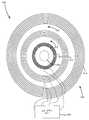
탱크 회로(208)의 일 실시예가 도 4에 도시되어 있으며, 개괄적으로 400으로 지정되어 있다. 탱크 회로(208)는 코일 선택기 회로(420) 및 1차 코일 어셈블리(408)를 포함한다. 1차 코일 어셈블리(408)는 선택적인 위치지정(positioning) 자석(420), 저전력 코일(410), 중간 전력 코일(412) 및 고전력 코일(414)을 포함한다. 현재의 실시예에서, 코일들 중 일부는 코일 선택기 회로로의 전기 접속을 공유한다. 구체적으로, 저전력 코일(410)은 중간 전력 코일(412)과 리드를 공유한다. 중간 전력 코일(412)은 고전력 코일(414)과 다른 리드를 공유한다.One embodiment of the tank circuit 208 is shown in FIG. 4 and is generally designated as 400. The tank circuit 208 includes a
물리적 특성들은 코일이 급전될 때 전송되는 전력을 만들어낸다. 그러한 특성들의 예는 기하구조, 길이, 게이지 및 권수를 포함한다. 코일들(414, 412, 410)의 물리적 특성 중 본질적으로 임의의 것이 달라질 수 있다. 도시된 실시예에서, 저전력 코일(512)은 중간 전력 코일(514)에 비해 상대적으로 짧은 길이 및 게이지를 갖고, 중간 전력 코일은 고전력 코일(514)보다 짧은 길이 및 게이지를 갖는다. 또한, 도 4에 도시된 코일들은 일반적으로 원형이다. 그러나, 코일들은 몇몇 예를 들자면 타원, 직사각형, 정사각형과 같은 다른 형상들을 이용하여 구현될 수 있다. 일 실시예에서, 다차원 코일들이 구현된다.Physical properties produce the transmitted power when the coil is fed. Examples of such properties include geometry, length, gauge, and number of turns. Essentially any of the physical characteristics of the
다른 인자들도 코일이 급전될 때 전송되는 전력을 만들어낼 수 있다. 예를 들어, 한가지 인자는 코일들(410, 412, 414) 간의 간격이다. 도 4에 도시된 실시예에서는, 혼신 또는 기타 간섭을 잠재적으로 감소시킬 수 있는 갭들(416, 418)이 코일들(410, 412, 414) 간에 존재한다. 현재의 실시예에서, 이러한 갭들(416, 418)은 공기로 채워지고, 코일들(410, 412, 414) 간에 소정의 격리를 제공하는 역할을 한다. 대안적인 실시예에서, 갭들(416, 418)은 추가의 격리를 제공하기 위해 차폐 재료로 채워질 수 있다. 다른 대안적인 실시예에서, 갭들(416, 418)은 코일들(410, 412, 414)에 의해 생성되는 자기장을 지향시키기 위해 페라이트(ferrite)로 채워질 수 있다. 도 6에 도시된 실시예에서, 코일들(610, 612, 614) 간의 간격은 제한된다. 코일들 간에는 갭이 없고, 이는 코일들이 그들의 크기를 유지하면서 더 컴팩트해질 수 있게 해 준다. 도 6의 실시예에서, 코일들은 코일 선택기 회로(620)로의 일부 리드들(leads)을 공유한다. 대안적인 실시예에서, 각각의 코일(610, 612, 614)은 코일 선택기 회로(620)로의 2개의 별개의 리드를 포함할 수 있다.Other factors can also produce the transmitted power when the coil is fed. For example, one factor is the spacing between
Ⅳ. 원격 장치IV. Remote device
2차 회로의 일 실시예가 도 3에 도시되어 있고, 개괄적으로 300으로 지정되어 있다. 도 3에 도시된 실시예에서, 2차 회로(300)는 일반적으로, 세컨더리(302), 정류기(304)(또는 AC 전력을 DC로 변환하기 위한 다른 컴포넌트들), 2차 제어기(316), 메모리(322), 무선 IR 송신기(320), 신호 저항기(318), 및 부하(306)를 포함한다. 다른 회로가 포함될 수 있다. 예를 들어, 대안적인 일 실시예에서, 수신되는 전력을 스케일링하기 위해 저전압 전력 공급장치가 포함될 수 있다. 다른 대안적인 실시예에서, 수신되는 전력을 필터링하거나 다르게 조절하기 위해 컨디셔닝 회로가 포함될 수 있다.One embodiment of the secondary circuit is shown in FIG. 3 and is generally designated as 300. 3, the secondary circuit 300 generally includes a secondary 302, a rectifier 304 (or other components for converting AC power to DC), a
도시된 실시예의 2차 코일(302)은 가변 전자기장이 존재하는 상태에서 전기를 발생시키기에 적합한 와이어의 코일이다. 아마도 도 5에 가장 잘 나타나 있는 바와 같이, 2차 코일(509)은 크기 및 형상면에서 1차 코일들(512, 514, 516) 중 하나에 대응할 수 있다. 예를 들어, 2개의 코일이 실질적으로 동일한 직경을 가질 수 있다. 일부 응용들에서, 2차 코일(509)은 리츠 와이어의 코일일 수 있다. 1차 코일들과 마찬가지로, 2차 코일(509)의 특성들은 응용마다 달라질 수 있다. 예를 들어, 2차 코일(509)의 권수, 크기, 형상, 구성 또는 다른 특성들이 달라질 수 있다. 또한, 길이, 게이지 및 와이어의 유형과 같은 와이어의 특성들이 달라질 수 있다. 와이어의 코일과 관련하여 설명되었지만, 대안적으로 2차 코일(509)은 의도된 전자기장에 응답하여 충분한 전기 전력을 발생시킬 수 있는, 본질적으로 임의의 구조일 수 있다.The
일부 대안적인 실시예에서, 원격 장치는 복수의 2차 코일을 가질 수 있다. 예를 들어, 원격 장치는 저전력 응용들을 위한 별개의 저전력 코일, 및 중간 전력 및 고전력 응용을 위한 별개의 중간 전력 및 고전력 코일들을 가질 수 있다. 다른 대안적인 실시예에서, 원격 장치는 원격 장치에 배향 및 공간적 자유를 주기 위해 복수의 2차 코일을 갖는다. In some alternative embodiments, the remote device may have a plurality of secondary coils. For example, the remote device may have separate low power coils for low power applications and separate intermediate power and high power coils for medium power and high power applications. In another alternative embodiment, the remote device has a plurality of secondary coils to provide orientation and spatial freedom to the remote device.
일 실시예에서, 리플 전압을 감소시키기 위해, 상이한 위상들의 전력을 수신하는 복수의 2차 코일들이 이용될 수 있다. 이것은 2007년 9월 9일에 출원되고 발명의 명칭이 "Multiphase Inductive Power Supply System"인 Baarman 등의 미국 특허 출원 제60/976,137호에 언급되며, 이 출원은 여기에 참조에 의해 포함된다. 그러한 실시예에서는, 복수의 코일을 각각 갖는 복수의 코일 어셈블리가 상이한 위상들에서 전력을 송신할 것으로 희망될 수 있다.In one embodiment, to reduce ripple voltage, a plurality of secondary coils may be used that receive power of different phases. This is referred to in U.S. Patent Application No. 60 / 976,137, filed September 9, 2007, entitled " Multiphase Inductive Power Supply System ", Baarman et al., Which is incorporated herein by reference. In such an embodiment, it may be desired that a plurality of coil assemblies, each having a plurality of coils, transmit power in different phases.
동작 시에, 정류기(304)는 2차 코일(302)에서 생성된 AC 전력을 DC 전력으로 변환한다. 일부 응용들에서, 정류기는 제거될 수 있다. 예를 들어, 부하(306)가 AC 전력을 수용하는 경우이다.In operation, the
2차 제어기(316)는 유도 전력 공급장치에 전력 수요 정보를 통신하기 위해 통신 시스템을 동작시킬 수 있는, 본질적으로 임의의 유형의 마이크로컨트롤러일 수 있다. 일부 실시예들에서, 2차 제어기(316)는 메모리를 포함한다. 도시된 실시예에서, 2차 회로는 외부 메모리(322)를 포함한다. 메모리는 일반적으로 전력 수요 정보를 포함하고, 원격 장치에 관한 추가의 정보를 포함할 수 있다. 전력 수요 정보는 원격 장치가 얼마나 많은 전력을 원하는지를 분류하는 전력 등급을 포함할 수 있다.The
일 실시예에서, 저전력 등급, 중간 전력 등급, 및 고전력 등급의 3가지 전력 등급이 있다. 저전력 등급은 0 내지 5 와트의 전력을 원하는 장치들로서 정의된다. 중간 전력 등급은 5 내지 110 와트의 전력을 원하는 장치들로서 정의된다. 고전력 등급은 110와트보다 많은 전력을 원하는 장치들로서 정의된다. 이러한 전력 등급 체계 하에서 저전력 등급 장치로 분류되는 장치들의 예는, 셀폰, MP3 플레이어 및 PDA(Personal Digital Assistant)를 포함한다. 중간 전력 등급을 갖는 장치들의 예는 랩탑 컴퓨터 및 기타 중간 전력 응용들을 포함한다. 고전력 장치들의 예는 블렌더 또는 프라이팬과 같은 주방 가전들을 포함한다. 대안적인 실시예에서, 상이한 전력 등급 체계를 이용하여 전력 등급들의 정의가 달라질 수 있다.In one embodiment, there are three power ratings: low power, medium power, and high power. A low power rating is defined as the desired devices with a power of 0 to 5 watts. The intermediate power rating is defined as the desired devices with a power of 5 to 110 watts. High power ratings are defined as devices that require more than 110 watts of power. Examples of devices classified as low power class devices under this power rating scheme include cell phones, MP3 players and PDAs (Personal Digital Assistants). Examples of devices having intermediate power ratings include laptop computers and other intermediate power applications. Examples of high power devices include kitchen appliances such as blenders or frying pans. In an alternative embodiment, the definition of the power ratings may be varied using different power rating schemes.
일 실시예에서, 신호 저항기(318)는 정보를 1차 제어기(202)에 보내기 위해 이용될 수 있다. 2차 회로(103)로부터 1차 회로(105)로의 통신을 제공하기 위해 신호 저항기(318)를 사용하는 것은 앞에서 참조에 의해 포함된 미국 특허 출원 제11/855,710호에서 논의되었다. 신호 저항기(318)는 분로(shunt)될 때, 과전류 또는 과전압 상태를 나타내는 통신 신호를 보낸다. 저항기가 분로될 때, 1차 회로(103) 상의 전류 또는 피크 검출기는 과전압/과전류 조건을 감지하고 그에 따라 동작할 수 있다. 본 발명의 신호 저항기(318)는 1차 제어기(202)에 추가의 데이터를 통신하기 위해 체계적으로(systematically) 분로될 수 있다. 예를 들어, 데이터 스트림이 전력 수요 정보를 표현할 수 있고, 또는 원격 장치에 관한 다른 정보를 제공할 수 있다. 대안적으로, 신호 저항기(318)는 다른 통신 시스템으로 완전히 교체될 수 있다. 예를 들어, 무선 송신기(320)는 1차 회로(200)의 무선 수신기(212)와 무선으로 통신하기 위해, 신호 저항기(318)와 함께 또는 신호 저항기(318)를 대신하여 이용될 수 있다. 대안적인 실시예에서, 무선 IR 송신기(320) 및 신호 저항기(318) 중 하나 또는 둘다는 유도 전력 공급장치와 통신하기 위한 다른 통신 시스템으로 교체될 수 있다. 예를 들어, WIFI, 적외선, 블루투스, 셀룰러 또는 RFID 통신 시스템 중 임의의 것이 원격 장치(104)에서 구현될 수 있다.In one embodiment, the
무선 송신기 또는 송수신기의 사용은 앞에서 참조에 의해 포함된 Baarman의 미국 특허 출원 공개 제2004/130915A1호에서 이전에 논의되었다. 구체적으로, 원격 장치와 유도 전력 공급장치 간에서 데이터를 무선으로 통신하기 위한 방법으로서 WIFI, 적외선, 블루투스, 셀룰러 또는 RFID를 사용하는 것이 이전에 논의되었다. 또한, 인덕션 코일 및 전력선 통신 프로토콜을 이용하는 통신이 논의되었다. 원격 장치로부터 유도 전력 공급장치로 원하는 데이터를 전송하기 위해, 데이터를 송신하는 이러한 방법들 중 임의의 것이 본 발명에서 구현될 수 있다.The use of a wireless transmitter or transceiver has been previously discussed in Baarman, U.S. Patent Application Publication No. 2004 / 130915A1, which is incorporated by reference above. Specifically, the use of WIFI, infrared, Bluetooth, cellular or RFID as a method for wirelessly communicating data between a remote device and an inductive power supply has been previously discussed. In addition, communications using induction coils and power line communication protocols have been discussed. Any of these methods of transmitting data may be implemented in the present invention to transmit the desired data from the remote device to the inductive power supply.
원격 장치 부하(306)는 본질적으로 임의의 적합한 부하일 수 있다. 일부 실시예들에서, 부하(306)는 재충전가능한 배터리일 수 있고, 2차 회로는 추가의 충전 회로를 포함할 수 있다. 다른 실시예들에서, 부하(306)는 원격 장치의 기능에 관련될 수 있다.The
Ⅴ. 방법Ⅴ. Way
인증 및 전력 전송 제어를 위한 방법이 도 9의 흐름도에 도시되어 있고, 개괄적으로 900으로 지정되어 있다. 방법은 핑(ping) 메시지를 주기적으로 송신하는 단계(902), 응답으로 수신된 임의의 메시지를 인증하는 단계(904), 인증(authentic) 메시지에 응답하여, CIDC(control identification class) 및 PPC(primary power class)를 결정하고, 결정된 CIDC 및 PPC에 기초하여 전력 전송을 시작하는 단계(906)를 포함한다. 액티브 전력 전송 모드(908) 동안, 원격 장치로부터의 제어 피드백 패킷들(912)을 이용하여 피드백 루프에서 장치의 존재 및 제어 포인트의 상태가 계속하여 체크된다(910).A method for authentication and power transfer control is shown in the flow chart of FIG. 9 and is generally designated 900. The method includes periodically sending a
일 실시예에서, 유도 전력 공급장치는 수가지 모드들 중 하나, 즉 핑 또는 액티브 전력 전송에 있다. 핑 모드는 자격있는 장치가 존재하는지 여부를 능동적으로 결정한다. 전력 전송은 장치 식별 등급이 인식되고 유효성이 검증되는 경우에만 발생한다.In one embodiment, the inductive power supply is in one of several modes, i.e., ping or active power transmission. Ping mode actively determines whether a qualified device exists. Power transmission occurs only when the device identification class is recognized and validated.
유도 전력 공급 시스템 내의 하드웨어의 특성들을 이용하여 안전 핑 주파수가 결정될 수 있다. 프라이머리는 지정된 핑 주파수에서 저전력(또는 다른) 코일에 급전함으로써 세컨더리와의 통신을 시도하고, 응답을 기다린다. 세컨더리가 충전 영역 내에 존재하면, 그 세컨더리는 핑 동작 동안에 보내진 에너지에 의해 충분히 전력을 공급받아서, 자기 자신을 초기화하고 전력 수요 정보를 포함할 수 있는 식별 메시지를 유도 전력 공급장치에 보낸다.The safety pin frequency can be determined using the characteristics of the hardware in the inductive power supply system. The primary tries to communicate with the secondary by feeding the low power (or other) coil at the designated ping frequency and waits for a response. If the secondary exists in the charging zone, the secondary is fully powered by the energy sent during the ping operation, initializing itself and sending an identification message to the inductive power supply that may contain power demand information.
프라이머리가 핑 동작 동안에 충전 필드 내의 장치를 검출하는 데에 실패한 경우, 다음의 검출 시도까지 코일 전력이 제거된다. 핑 동작 동안에 장치가 검출되는 경우, 프라이머리는 전력 전송을 시작하려는 시도로, 확립된 초기 동작 주파수로 복귀한다. 전송 동안 세컨더리에 전달되는 전력은 세컨더리로부터 수신된 통신에 기초하여 제어될 수 있다.If the primary fails to detect the device in the charge field during the ping operation, the coil power is removed until the next detection attempt. If a device is detected during a ping operation, the primary returns to the established initial operating frequency in an attempt to start power transmission. The power delivered to the secondary during transmission can be controlled based on the communication received from the secondary.
제어 식별 등급들은 유도 전력 공급장치가 원격 장치를 충전 또는 전력공급하기 위해 사용할 상이한 제어 방법들을 식별할 수 있다. 제어 식별 등급들의 예들은 충전 세트 포인트 제어, 충전 오류 제어, 전력 공급 세트 포인트 제어, 전력 공급 오류 제어, 및 전력 공급 지시 제어를 포함한다.The control identification classes may identify different control methods that the inductive power supply will use to charge or power the remote device. Examples of control identification classes include charge set point control, charge error control, power supply set point control, power supply error control, and power supply indication control.
1차 전력 등급은 유도 전력 공급장치의 특정 코일의 전력 범위를 결정한다. 1차 전력 등급은 또한 코일 기하구조 및 매개변수 사양에 영향을 줄 수 있다. 대안적인 실시예에서, 1차 전력 등급은 유도 전력 공급장치에 의해 제공되는 전체 전력 범위에 관한 정보를 포함한다. 원격 장치는 유도 전력 공급장치에 송신된 전력 수요 정보 내에 원격 장치 전력 등급을 포함할 수 있다. 원격 장치 전력 등급 및 1차 전력 등급은 동일한 하나일 수 있고, 또는 서로 다를 수 있다.The primary power rating determines the power range of a particular coil of the inductive power supply. The primary power rating may also affect the coil geometry and parameter specifications. In an alternative embodiment, the primary power rating includes information regarding the total power range provided by the inductive power supply. The remote device may include the remote device power rating in the power demand information sent to the inductive power supply. The remote device power rating and the primary power rating may be the same or may be different.
일 실시예에서, 전력 등급은 원격 장치로부터 유도 전력 공급장치로 통신되는 정보의 일부분이다. 일 실시예에서, 원격 장치가 요구할 것으로 예상될 수 있는 전력의 최대 양에 관한 정보가 1차 회로에 제공될 수 있다. 예를 들어, 셀폰은 3.5W 최대 전력 레벨 아래에 들 수 있다. 그것의 전력 등급 바이트는 0000 0111b일 것이다.In one embodiment, the power rating is part of the information communicated from the remote device to the inductive power supply. In one embodiment, information regarding the maximum amount of power that a remote device may be expected to require may be provided to the primary circuit. For example, a cell phone may be below a 3.5W maximum power level. Its power rating byte will be 0000 0111b.
이하의 표는 전력 등급 바이트가 어떻게 구성될 수 있는지를 설명한다. 전력 등급은 본질적으로 임의의 방식으로 인코딩될 수 있으며, 이 표는 단순히 하나의 가능한 실시예를 나타내는 것이다.The following table describes how power class bytes can be configured. The power ratings can be encoded in essentially any manner, and this table simply represents one possible embodiment.

도 10은 본 발명의 일 실시예에 따라 전력을 제공하기 위한 기능적 블록도를 도시하고 있다. 도 11은 본 발명의 일 실시예에 따라 전력을 수신하기 위한 기능적 블록도를 도시하고 있다. 도 12는 본 발명의 다른 실시예에 따라 전력을 제공하기 위한 기능적 블록도를 도시하고 있다. 도 13은 본 발명의 다른 실시예에 따라 전력을 수신하기 위한 기능적 블록도를 도시하고 있다.10 illustrates a functional block diagram for providing power in accordance with one embodiment of the present invention. Figure 11 illustrates a functional block diagram for receiving power in accordance with one embodiment of the present invention. Figure 12 shows a functional block diagram for providing power in accordance with another embodiment of the present invention. Figure 13 shows a functional block diagram for receiving power in accordance with another embodiment of the present invention.
도 10 및 도 11의 기능적 블록도는 원격 장치 내의 부하를 유도 충전하는 것에 관한 것이다. 도 12 및 도 13의 기능적 블록도는 원격 장치 내의 재충전가능한 배터리를 유도 충전하는 것에 관한 것이다.The functional block diagrams of Figures 10 and 11 relate to inductive charging of a load in a remote device. The functional block diagram of Figures 12 and 13 relates to inductive charging of a rechargeable battery in a remote device.
도 10 및 도 12에서, 코일들 각각은 위에서 설명된 것과 같은 복수의 코일들을 갖는 1차 코일 어셈블리를 나타낼 수 있다. 대안적으로, 코일들 각각은 1차 코일 어셈블리의 한 코일을 나타낼 수 있다.In Figures 10 and 12, each of the coils may represent a primary coil assembly having a plurality of coils as described above. Alternatively, each of the coils may represent one coil of the primary coil assembly.
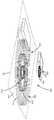
위에서, 복수 코일 유도 전력 공급장치들의 몇몇 실시예가 기술되었다. 구체적으로, 멀티탭 구성으로 구성된 복수의 코일을 이용하는 복수의 코일 유도 전력 공급장치들, 및 별개의 코일 구성을 이용하는 복수 코일 유도 전력 공급장치들의 예들이 제공되었다. 가변 인덕턴스를 제공하는 다른 구성들도 제공될 수 있다. 예를 들어, 도 15에 도시된 리츠 와이어 코일과 같이 세그먼트화된 프라이머리는 가변 양의 인덕턴스를 제공하기 위해 다양한 구성으로 접속되고 급전될 수 있는 복수의 스트랜드를 제공할 수 있다. 세그먼트화된 프라이머리의 다양한 구성들은 유도 전력 공급장치가 동일한 프라이머리를 이용하여 고전력 레벨로부터 저전력 레벨까지 2차 전력 및 커플링 요건에 더 잘 매칭할 수 있게 해 준다. 현재의 실시예에서, 탭 및 세그먼트 구성의 조합은 광범위한 인덕턴스 값 및 와이어 게이지를 제공한다. 일부 실시예들에서, 세그먼트들 중 일부가 분리되어, 더 넓은 범위를 허용할 수 있다.Several embodiments of the multiple coil inductive power supplies have been described above. Specifically, there have been provided examples of a plurality of coil inductive power supplies using a plurality of coils configured in a multi-tap configuration, and a plurality of coil inductive power supplies using a separate coil configuration. Other configurations that provide variable inductance may also be provided. For example, a segmented primary, such as the Litz wire coil shown in FIG. 15, can provide a plurality of strands that can be connected and fed in various configurations to provide a variable amount of inductance. The various configurations of the segmented primary enable the inductive power supply to better match the secondary power and coupling requirements from the high power level to the low power level using the same primary. In the current embodiment, a combination of taps and segment configurations provides a wide range of inductance values and wire gauges. In some embodiments, some of the segments may be separate, allowing for a wider range.
스트랜드들이 어떻게 접속되는지에 따라, 상이한 구성들이 생성될 수 있다. 이하의 표는 다양한 코일 선택 회로 세그먼트 옵션들의 다수의 예를 기술한다.Depending on how the strands are connected, different configurations can be created. The following table describes a number of examples of various coil select circuit segment options.

도 15는 4개의 섹션으로 세그먼트화된 리츠 와이어의 단면도를 도시한다. 도시된 실시예에서, 각 섹션은 개별적으로 급전될 수 있다. 대안적인 실시예에서, 섹션들은 다르게 분할될 수 있고, 또는 각각의 스트랜드가 따로 급전될 수 있다. 또한, 현재의 실시예에서, 코일 선택기 회로가 각각의 탭에서 따로 각각의 세그먼트에 접속되어, 세그먼트들은 코일 선택기 회로가 다양한 세그먼트들을 함께 어떻게 접속하는지에 따라 병렬 또는 직렬로 배열될 수 있게 된다.Figure 15 shows a cross-sectional view of a Litz wire segmented into four sections. In the illustrated embodiment, each section can be individually powered. In an alternative embodiment, the sections can be divided differently, or each strand can be fed separately. Also, in the current embodiment, a coil selector circuit is connected to each segment separately in each tap so that the segments can be arranged in parallel or in series, depending on how the coil selector circuit connects the various segments together.
도 15는 다양한 게이지의 3개의 코일(610, 612, 614)을 도시하고 있다. 대안적인 실시예에서, 각각의 코일은 동일한 게이지를 가질 수 있고, 게이지는 어느 세그먼트 또는 개별 스트랜드를 급전할 것인지를 선택하는 코일 선택기 회로에 의해 제어될 수 있다.Figure 15 shows three
다른 유도 전력 공급장치 실시예들과 관련하여 위에서 기술된 바와 같이, 코일 선택기 회로는 제어기(202) 내의 메모리에 상주하는 프로그램에 따라 제어될 수 있다. 코일 선택기 회로는 원격 장치로부터 제공되는 전력 수요 정보에 기초하여 조정하기 위해, 동작 동안 세그먼트화된 프라이머리의 구성을 변경할 수 있다. 와이어의 게이지 및 다른 특성들을 동적으로 변경하는 능력은 2차 전력과 커플링 요건들을 더 잘 매칭시키는 데에 유용하다.As described above with respect to other inductive power supply embodiments, the coil selector circuit can be controlled in accordance with a program resident in the memory in the
위의 설명은 본 발명의 현재 실시예에 관한 것이다. 본 발명의 취지 및 더 넓은 양태들을 벗어나지 않고서 다양한 변경 및 변화가 이루어질 수 있다.The foregoing description is of a current embodiment of the invention. Various changes and modifications can be made without departing from the spirit and broader aspects of the present invention.
배타적 소유권 또는 특권이 청구되는 본 발명의 실시예들은 다음과 같이 정의된다.Embodiments of the present invention in which exclusive rights or privileges are claimed are defined as follows.
Claims (40)
Translated fromKorean복수의 세그먼트들를 포함하는 단일 코일 - 상기 세그먼트들 각각은 서로 분리된 하나 이상의 스트랜드(strand)를 포함하며, 상기 단일 코일은 상기 원격 장치에 무선으로 전력을 전송하기 위해 급전가능함(energizable) -;
복수의 스위치들; 및
상기 복수의 세그먼트들의 병렬 구조, 병렬 및 직렬 구조, 또는 직렬 구조를 형성하기 위해서 상기 복수의 세그먼트들을 설정하는 상기 스위치들을 선택가능하게 설정하는 제어기
를 포함하는 유도 전력 공급장치.An inductive power supply for providing wireless power to a remote device,
A single coil comprising a plurality of segments, each of said segments comprising one or more strands separated from each other, said single coil being energizable to transmit power wirelessly to said remote device;
A plurality of switches; And
A controller for selectively configuring the switches to set the plurality of segments to form a parallel structure, a parallel and a series structure, or a series structure of the plurality of segments,
/ RTI >
상기 제어기는 상기 원격 장치에 의해 요구되는 전력 및 상기 원격 장치에 의한 상기 단일 코일에 대한 커플링 요구를 수용하기 위해 상기 복수의 세그먼트들을 설정하는 상기 스위치들을 선택가능하게 설정하도록 프로그램되는 유도 전력 공급장치.The method according to claim 1,
Wherein the controller is programmed to selectively set the switches to set the plurality of segments to accommodate the power required by the remote device and the coupling request for the single coil by the remote device. .
상기 제어기는 상기 원격 장치로부터 수신된 전력 요구 정보의 함수로서 상기 복수의 세그먼트들을 설정하는 상기 스위치들을 선택가능하게 설정하도록 프로그램되는 유도 전력 공급장치.The method according to claim 1,
Wherein the controller is programmed to selectively set the switches to set the plurality of segments as a function of power request information received from the remote device.
상기 제어기는, 상기 복수의 세그먼트들의 상기 병렬 구조, 상기 병렬 및 직렬 구조와, 상기 직렬 구조 간에 상기 복수의 세그먼트들을 설정하는 상기 스위치들을 선택가능하게 설정하도록 프로그램되는 유도 전력 공급장치.The method according to claim 1,
Wherein the controller is programmed to selectively set the switches to set the plurality of segments between the parallel structure of the plurality of segments, the parallel and serial structure, and the serial structure.
상기 제어기는, 상기 복수의 세그먼트들의 상기 병렬 구조, 상기 병렬 및 직렬 구조와, 상기 직렬 구조 각각에 상이한 수의 실제 턴(turn)들을 제공하도록 상기 복수의 세그먼트들을 설정하는 상기 스위치들을 선택가능하게 설정하도록 프로그램되는 유도 전력 공급장치.The method according to claim 1,
Wherein the controller is operable to selectively configure the switches to set the plurality of segments to provide a different number of actual turns for each of the parallel structures, the parallel and series structures of the plurality of segments, Lt; / RTI >
상기 제어기는 상기 복수의 세그먼트들의 상기 병렬 구조, 상기 병렬 및 직렬 구조와, 상기 직렬 구조 각각에 상이한 실제 게이지 값(gauge value)을 제공하도록 상기 복수의 세그먼트들을 설정하는 상기 스위치들을 선택가능하게 설정하도록 프로그램되는 유도 전력 공급장치.The method according to claim 1,
Wherein the controller is configured to selectably configure the switches to set the plurality of segments to provide a different actual gauge value for each of the parallel structures, the parallel and series structures of the plurality of segments, and each of the series structures Programmed inductive power supply.
상기 복수의 세그먼트들은 복수의 릿츠(litz) 와이어 프라이머리 세그먼트들인 유도 전력 공급장치.The method according to claim 1,
Wherein the plurality of segments are a plurality of litz wire primary segments.
상기 복수의 세그먼트들의 상기 병렬 구조, 상기 병렬 및 직렬 구조와, 상기 직렬 구조 각각은 상이한 양의 인덕턴스를 갖는 유도 전력 공급장치.The method according to claim 1,
Wherein the parallel structure, the parallel and series structure of the plurality of segments, and each of the series structures have different amounts of inductance.
복수의 세그먼트들를 포함하는 단일 코일을 제공하는 단계 - 상기 세그먼트들 각각은 서로 분리된 하나 이상의 스트랜드(strand)를 포함하며, 상기 단일 코일은 상기 원격 장치에 무선으로 전력을 전송하기 위해 급전가능함(energizable) -;
복수의 스위치들을 제공하는 단계; 및
상기 복수의 세그먼트들의 병렬 구조, 병렬 및 직렬 구조, 또는 직렬 구조를 형성하기 위해서 상기 복수의 세그먼트들을 설정하는 상기 스위치들을 선택가능하도록 설정하는 단계
를 포함하는 유도 전력 공급장치를 동작시키는 방법.CLAIMS What is claimed is: 1. A method of operating an inductive power supply for providing wireless power to a remote device,
Providing a single coil comprising a plurality of segments, each of the segments comprising one or more strands separated from each other, the single coil being energizable ) -;
Providing a plurality of switches; And
Setting the switches that set the plurality of segments to be selectable to form a parallel structure, a parallel and a series structure, or a series structure of the plurality of segments
≪ / RTI >
상기 원격 장치에 의해 요구되는 전력 및 상기 원격 장치에 의한 상기 단일 코일에 대한 커플링 요구를 수용하기 위해 상기 복수의 세그먼트들을 설정하는 상기 스위치들을 선택가능하도록 설정하는 단계를 포함하는 유도 전력 공급장치를 동작시키는 방법.11. The method of claim 10,
Setting the switches to set the plurality of segments to be selectable to accommodate the power required by the remote device and the coupling request for the single coil by the remote device How to operate.
상기 원격 장치로부터 수신된 전력 요구 정보의 함수로서 상기 복수의 세그먼트들을 설정하는 상기 스위치들을 선택가능하도록 설정하는 단계를 포함하는 유도 전력 공급장치를 동작시키는 방법.11. The method of claim 10,
And setting the switches that set the plurality of segments as a function of the power request information received from the remote device to be selectable.
상기 복수의 세그먼트들의 상기 병렬 구조, 상기 병렬 및 직렬 구조와, 상기 직렬 구조 각각에 상이한 수의 실제 턴들을 제공하도록 상기 복수의 세그먼트들을 설정하는 상기 스위치들을 선택가능하도록 설정하는 단계를 포함하는 유도 전력 공급장치를 동작시키는 방법.11. The method of claim 10,
Selecting the switches to set the plurality of segments to provide a different number of actual turns in each of the parallel structures, the parallel and series structures of the plurality of segments, and each of the series structures; A method for operating a feeding device.
상기 복수의 세그먼트들의 상기 병렬 구조, 상기 병렬 및 직렬 구조와, 상기 직렬 구조 각각에 상이한 실제 게이지 값을 제공하도록 상기 복수의 세그먼트들을 설정하는 상기 스위치들을 선택가능하도록 설정하는 단계를 포함하는 유도 전력 공급장치를 동작시키는 방법.11. The method of claim 10,
Selecting the switches to set the plurality of segments to provide different actual gauge values for each of the parallel structures, the parallel and series structures of the plurality of segments, and each of the series structures; A method for operating a device.
상기 복수의 세그먼트들은 단일 릿츠(litz) 와이어 코일을 형성하는 유도 전력 공급장치를 동작시키는 방법.11. The method of claim 10,
Wherein the plurality of segments form a single RITZ wire coil.
상기 복수의 세그먼트들의 상기 병렬 구조, 상기 병렬 및 직렬 구조와, 상기 직렬 구조 각각은 상이한 양의 인덕턴스를 갖는 유도 전력 공급장치를 동작시키는 방법.11. The method of claim 10,
Wherein the parallel structure, the parallel and series structures of the plurality of segments, and each of the series structures have different amounts of inductance.
세그먼트화된 프라이머리 수단 - 상기 세그먼트화된 프라이머리 수단은 복수의 세그먼트들을 포함하며, 상기 세그먼트들 각각은 서로 분리된 하나 이상의 스트랜드를 포함하고, 상기 세그먼트화된 프라이머리 수단은 원격 장치에 무선으로 전력을 전송하기 위해 급전가능함 -;
복수의 스위치들; 및
복수의 상이한 직렬 및 병렬 전기 구조들 간에 상기 세그먼트화된 프라이머리 수단을 구성하기 위해 상기 복수의 스위치들을 선택가능하도록 설정하는 제어기
를 포함하는 유도 전력 공급장치.An inductive power supply for providing wireless power to a remote device,
Segmented primary means, said segmented primary means comprising a plurality of segments, each of said segments comprising one or more strands separated from one another, said segmented primary means comprising means for wirelessly Power can be fed to transmit power;
A plurality of switches; And
A controller for setting the plurality of switches to be selectable for configuring the segmented primary means between a plurality of different series and parallel electrical structures,
/ RTI >
상기 제어기는 상기 원격 장치에 의해 요구되는 전력 및 상기 원격 장치에 의한 상기 세그먼트화된 프라이머리 수단에 대한 커플링 요구를 수용하기 위해 상기 복수의 세그먼트들을 설정하는 상기 스위치들을 선택가능하게 설정하도록 프로그램되는 유도 전력 공급장치.20. The method of claim 19,
The controller is programmed to selectively set the switches that set the plurality of segments to accommodate the power required by the remote device and the coupling request for the segmented primary means by the remote device Inductive power supply.
상기 제어기는 상기 원격 장치로부터 수신된 전력 요구 정보의 함수로서 상기 세그먼트화된 프라이머리 수단을 선택가능하게 설정하도록 프로그램되는 유도 전력 공급장치.20. The method of claim 19,
Wherein the controller is programmed to selectively set the segmented primary means as a function of power demand information received from the remote device.
상기 제어기는 병렬 전기 구조, 병렬 및 직렬 전기 구조, 및 직렬 전기 구조 간에 상기 세그먼트화된 프라이머리 수단을 선택가능하게 설정하도록 프로그램되는 유도 전력 공급장치.20. The method of claim 19,
Wherein the controller is programmed to selectively set the segmented primary means between a parallel electrical structure, a parallel and a series electrical structure, and a series electrical structure.
상기 제어기는 상기 복수의 상이한 전기 구조들의 각각에 상이한 수의 실제 턴들을 제공하도록 상기 세그먼트화된 프라이머리 수단을 선택가능하게 설정하도록 프로그램되는 유도 전력 공급장치.20. The method of claim 19,
Wherein the controller is programmed to selectively set the segmented primary means to provide a different number of actual turns for each of the plurality of different electrical structures.
상기 제어기는 상기 복수의 상이한 전기 구조들의 각각에 상이한 실제 게이지 값을 제공하도록 상기 세그먼트화된 프라이머리 수단을 선택가능하게 설정하도록 프로그램되는 유도 전력 공급장치.20. The method of claim 19,
Wherein the controller is programmed to selectively set the segmented primary means to provide different actual gauge values for each of the plurality of different electrical structures.
상기 세그먼트화된 프라이머리 수단은 세그먼트화된 릿츠(litz) 와이어 프라이머리 수단인 유도 전력 공급장치.20. The method of claim 19,
Wherein the segmented primary means is a segmented litz wire primary means.
상기 복수의 상이한 직렬 및 병렬 전기 구조들 각각은 상이한 양의 인덕턴스를 갖는 유도 전력 공급장치.20. The method of claim 19,
Wherein each of the plurality of different series and parallel electrical structures has a different amount of inductance.
Applications Claiming Priority (3)
| Application Number | Priority Date | Filing Date | Title |
|---|---|---|---|
| US3645908P | 2008-03-13 | 2008-03-13 | |
| US61/036,459 | 2008-03-13 | ||
| PCT/US2009/036922WO2009114671A1 (en) | 2008-03-13 | 2009-03-12 | Inductive power supply system with multiple coil primary |
Related Parent Applications (1)
| Application Number | Title | Priority Date | Filing Date |
|---|---|---|---|
| KR1020107020297ADivisionKR101593250B1 (en) | 2008-03-13 | 2009-03-12 | Inductive power supply system with multiple coil primary |
Related Child Applications (1)
| Application Number | Title | Priority Date | Filing Date |
|---|---|---|---|
| KR1020167011811ADivisionKR101763547B1 (en) | 2008-03-13 | 2009-03-12 | Method of inductive power transfer to remote device and inductive power supply for transferring power to remote device |
Publications (2)
| Publication Number | Publication Date |
|---|---|
| KR20160017134A KR20160017134A (en) | 2016-02-15 |
| KR101651806B1true KR101651806B1 (en) | 2016-08-26 |
Family
ID=40561826
Family Applications (3)
| Application Number | Title | Priority Date | Filing Date |
|---|---|---|---|
| KR1020107020297AActiveKR101593250B1 (en) | 2008-03-13 | 2009-03-12 | Inductive power supply system with multiple coil primary |
| KR1020167011811AActiveKR101763547B1 (en) | 2008-03-13 | 2009-03-12 | Method of inductive power transfer to remote device and inductive power supply for transferring power to remote device |
| KR1020167002667AActiveKR101651806B1 (en) | 2008-03-13 | 2009-03-12 | Inductive power supply system with multiple coil primary |
Family Applications Before (2)
| Application Number | Title | Priority Date | Filing Date |
|---|---|---|---|
| KR1020107020297AActiveKR101593250B1 (en) | 2008-03-13 | 2009-03-12 | Inductive power supply system with multiple coil primary |
| KR1020167011811AActiveKR101763547B1 (en) | 2008-03-13 | 2009-03-12 | Method of inductive power transfer to remote device and inductive power supply for transferring power to remote device |
Country Status (10)
| Country | Link |
|---|---|
| US (3) | US8338990B2 (en) |
| EP (1) | EP2266179A1 (en) |
| JP (2) | JP5612489B2 (en) |
| KR (3) | KR101593250B1 (en) |
| CN (2) | CN103944196B (en) |
| AU (1) | AU2009223084A1 (en) |
| CA (1) | CA2715984A1 (en) |
| RU (1) | RU2010141703A (en) |
| TW (2) | TWI488400B (en) |
| WO (1) | WO2009114671A1 (en) |
Families Citing this family (377)
| Publication number | Priority date | Publication date | Assignee | Title |
|---|---|---|---|---|
| US7825543B2 (en) | 2005-07-12 | 2010-11-02 | Massachusetts Institute Of Technology | Wireless energy transfer |
| CN101860089B (en) | 2005-07-12 | 2013-02-06 | 麻省理工学院 | wireless non-radiative energy transfer |
| KR100819604B1 (en)* | 2005-07-27 | 2008-04-03 | 엘에스전선 주식회사 | Wireless Charger Decreased in Variation of Charging Efficiency |
| US11201500B2 (en) | 2006-01-31 | 2021-12-14 | Mojo Mobility, Inc. | Efficiencies and flexibilities in inductive (wireless) charging |
| US8115448B2 (en) | 2007-06-01 | 2012-02-14 | Michael Sasha John | Systems and methods for wireless power |
| US9421388B2 (en) | 2007-06-01 | 2016-08-23 | Witricity Corporation | Power generation for implantable devices |
| GB0716679D0 (en) | 2007-08-28 | 2007-10-03 | Fells J | Inductive power supply |
| US8884468B2 (en) | 2007-12-21 | 2014-11-11 | Access Business Group International Llc | Circuitry for inductive power transfer |
| US8855554B2 (en)* | 2008-03-05 | 2014-10-07 | Qualcomm Incorporated | Packaging and details of a wireless power device |
| CN102084442B (en) | 2008-03-17 | 2013-12-04 | 鲍尔马特技术有限公司 | Inductive transmission system |
| US20110050164A1 (en) | 2008-05-07 | 2011-03-03 | Afshin Partovi | System and methods for inductive charging, and improvements and uses thereof |
| CN102099958B (en) | 2008-05-14 | 2013-12-25 | 麻省理工学院 | Wireless power transfer including interference enhancement |
| US11979201B2 (en) | 2008-07-02 | 2024-05-07 | Powermat Technologies Ltd. | System and method for coded communication signals regulating inductive power transmissions |
| US7893564B2 (en)* | 2008-08-05 | 2011-02-22 | Broadcom Corporation | Phased array wireless resonant power delivery system |
| US8922066B2 (en) | 2008-09-27 | 2014-12-30 | Witricity Corporation | Wireless energy transfer with multi resonator arrays for vehicle applications |
| US8686598B2 (en) | 2008-09-27 | 2014-04-01 | Witricity Corporation | Wireless energy transfer for supplying power and heat to a device |
| US9515494B2 (en) | 2008-09-27 | 2016-12-06 | Witricity Corporation | Wireless power system including impedance matching network |
| US8324759B2 (en) | 2008-09-27 | 2012-12-04 | Witricity Corporation | Wireless energy transfer using magnetic materials to shape field and reduce loss |
| US8461720B2 (en) | 2008-09-27 | 2013-06-11 | Witricity Corporation | Wireless energy transfer using conducting surfaces to shape fields and reduce loss |
| US8400017B2 (en) | 2008-09-27 | 2013-03-19 | Witricity Corporation | Wireless energy transfer for computer peripheral applications |
| US8643326B2 (en) | 2008-09-27 | 2014-02-04 | Witricity Corporation | Tunable wireless energy transfer systems |
| US9105959B2 (en) | 2008-09-27 | 2015-08-11 | Witricity Corporation | Resonator enclosure |
| US9601261B2 (en) | 2008-09-27 | 2017-03-21 | Witricity Corporation | Wireless energy transfer using repeater resonators |
| US9544683B2 (en) | 2008-09-27 | 2017-01-10 | Witricity Corporation | Wirelessly powered audio devices |
| US8461722B2 (en) | 2008-09-27 | 2013-06-11 | Witricity Corporation | Wireless energy transfer using conducting surfaces to shape field and improve K |
| US8552592B2 (en) | 2008-09-27 | 2013-10-08 | Witricity Corporation | Wireless energy transfer with feedback control for lighting applications |
| US8901779B2 (en) | 2008-09-27 | 2014-12-02 | Witricity Corporation | Wireless energy transfer with resonator arrays for medical applications |
| US9744858B2 (en) | 2008-09-27 | 2017-08-29 | Witricity Corporation | System for wireless energy distribution in a vehicle |
| US9601266B2 (en) | 2008-09-27 | 2017-03-21 | Witricity Corporation | Multiple connected resonators with a single electronic circuit |
| US8963488B2 (en) | 2008-09-27 | 2015-02-24 | Witricity Corporation | Position insensitive wireless charging |
| US8487480B1 (en) | 2008-09-27 | 2013-07-16 | Witricity Corporation | Wireless energy transfer resonator kit |
| US9184595B2 (en) | 2008-09-27 | 2015-11-10 | Witricity Corporation | Wireless energy transfer in lossy environments |
| US8476788B2 (en) | 2008-09-27 | 2013-07-02 | Witricity Corporation | Wireless energy transfer with high-Q resonators using field shaping to improve K |
| US9601270B2 (en) | 2008-09-27 | 2017-03-21 | Witricity Corporation | Low AC resistance conductor designs |
| US9396867B2 (en) | 2008-09-27 | 2016-07-19 | Witricity Corporation | Integrated resonator-shield structures |
| US8957549B2 (en) | 2008-09-27 | 2015-02-17 | Witricity Corporation | Tunable wireless energy transfer for in-vehicle applications |
| US9065423B2 (en) | 2008-09-27 | 2015-06-23 | Witricity Corporation | Wireless energy distribution system |
| US8723366B2 (en) | 2008-09-27 | 2014-05-13 | Witricity Corporation | Wireless energy transfer resonator enclosures |
| US8907531B2 (en) | 2008-09-27 | 2014-12-09 | Witricity Corporation | Wireless energy transfer with variable size resonators for medical applications |
| US8497601B2 (en) | 2008-09-27 | 2013-07-30 | Witricity Corporation | Wireless energy transfer converters |
| US8629578B2 (en) | 2008-09-27 | 2014-01-14 | Witricity Corporation | Wireless energy transfer systems |
| US8410636B2 (en) | 2008-09-27 | 2013-04-02 | Witricity Corporation | Low AC resistance conductor designs |
| US20120091794A1 (en)* | 2008-09-27 | 2012-04-19 | Campanella Andrew J | Wirelessly powered laptop and desktop environment |
| US9106203B2 (en) | 2008-09-27 | 2015-08-11 | Witricity Corporation | Secure wireless energy transfer in medical applications |
| US8928276B2 (en) | 2008-09-27 | 2015-01-06 | Witricity Corporation | Integrated repeaters for cell phone applications |
| US8466583B2 (en) | 2008-09-27 | 2013-06-18 | Witricity Corporation | Tunable wireless energy transfer for outdoor lighting applications |
| US8569914B2 (en) | 2008-09-27 | 2013-10-29 | Witricity Corporation | Wireless energy transfer using object positioning for improved k |
| US8947186B2 (en) | 2008-09-27 | 2015-02-03 | Witricity Corporation | Wireless energy transfer resonator thermal management |
| US9318922B2 (en) | 2008-09-27 | 2016-04-19 | Witricity Corporation | Mechanically removable wireless power vehicle seat assembly |
| US8304935B2 (en) | 2008-09-27 | 2012-11-06 | Witricity Corporation | Wireless energy transfer using field shaping to reduce loss |
| US8598743B2 (en) | 2008-09-27 | 2013-12-03 | Witricity Corporation | Resonator arrays for wireless energy transfer |
| US8901778B2 (en) | 2008-09-27 | 2014-12-02 | Witricity Corporation | Wireless energy transfer with variable size resonators for implanted medical devices |
| US8471410B2 (en) | 2008-09-27 | 2013-06-25 | Witricity Corporation | Wireless energy transfer over distance using field shaping to improve the coupling factor |
| EP3179640A1 (en) | 2008-09-27 | 2017-06-14 | WiTricity Corporation | Wireless energy transfer systems |
| US9160203B2 (en) | 2008-09-27 | 2015-10-13 | Witricity Corporation | Wireless powered television |
| US8692410B2 (en) | 2008-09-27 | 2014-04-08 | Witricity Corporation | Wireless energy transfer with frequency hopping |
| US9246336B2 (en) | 2008-09-27 | 2016-01-26 | Witricity Corporation | Resonator optimizations for wireless energy transfer |
| US8912687B2 (en) | 2008-09-27 | 2014-12-16 | Witricity Corporation | Secure wireless energy transfer for vehicle applications |
| US8692412B2 (en) | 2008-09-27 | 2014-04-08 | Witricity Corporation | Temperature compensation in a wireless transfer system |
| US9093853B2 (en) | 2008-09-27 | 2015-07-28 | Witricity Corporation | Flexible resonator attachment |
| US8933594B2 (en) | 2008-09-27 | 2015-01-13 | Witricity Corporation | Wireless energy transfer for vehicles |
| US8772973B2 (en) | 2008-09-27 | 2014-07-08 | Witricity Corporation | Integrated resonator-shield structures |
| US9577436B2 (en) | 2008-09-27 | 2017-02-21 | Witricity Corporation | Wireless energy transfer for implantable devices |
| US8669676B2 (en) | 2008-09-27 | 2014-03-11 | Witricity Corporation | Wireless energy transfer across variable distances using field shaping with magnetic materials to improve the coupling factor |
| US9035499B2 (en) | 2008-09-27 | 2015-05-19 | Witricity Corporation | Wireless energy transfer for photovoltaic panels |
| US8937408B2 (en) | 2008-09-27 | 2015-01-20 | Witricity Corporation | Wireless energy transfer for medical applications |
| US8587155B2 (en) | 2008-09-27 | 2013-11-19 | Witricity Corporation | Wireless energy transfer using repeater resonators |
| US8441154B2 (en) | 2008-09-27 | 2013-05-14 | Witricity Corporation | Multi-resonator wireless energy transfer for exterior lighting |
| US8587153B2 (en) | 2008-09-27 | 2013-11-19 | Witricity Corporation | Wireless energy transfer using high Q resonators for lighting applications |
| US8482158B2 (en) | 2008-09-27 | 2013-07-09 | Witricity Corporation | Wireless energy transfer using variable size resonators and system monitoring |
| US8946938B2 (en) | 2008-09-27 | 2015-02-03 | Witricity Corporation | Safety systems for wireless energy transfer in vehicle applications |
| US8461721B2 (en)* | 2008-09-27 | 2013-06-11 | Witricity Corporation | Wireless energy transfer using object positioning for low loss |
| US8362651B2 (en) | 2008-10-01 | 2013-01-29 | Massachusetts Institute Of Technology | Efficient near-field wireless energy transfer using adiabatic system variations |
| EP2345552B1 (en)* | 2008-10-09 | 2019-11-20 | Toyota Jidosha Kabushiki Kaisha | Electrical powered vehicle |
| JP5287863B2 (en)* | 2008-10-09 | 2013-09-11 | トヨタ自動車株式会社 | Non-contact power receiving apparatus and vehicle equipped with the same |
| US9178376B2 (en) | 2008-12-12 | 2015-11-03 | Hanrim Postech Co., Ltd. | Non-contact charging station with power transmission planar spiral core, non-contact power-receiving apparatus, and method for controlling the same |
| US8427330B2 (en)* | 2009-02-06 | 2013-04-23 | Broadcom Corporation | Efficiency indicator for increasing efficiency of wireless power transfer |
| US8427100B2 (en)* | 2009-02-06 | 2013-04-23 | Broadcom Corporation | Increasing efficiency of wireless power transfer |
| US20100201310A1 (en)* | 2009-02-06 | 2010-08-12 | Broadcom Corporation | Wireless power transfer system |
| US11476566B2 (en) | 2009-03-09 | 2022-10-18 | Nucurrent, Inc. | Multi-layer-multi-turn structure for high efficiency wireless communication |
| JP5173901B2 (en)* | 2009-03-13 | 2013-04-03 | 三菱電機株式会社 | Contactless power supply / reception device |
| JP5365276B2 (en)* | 2009-03-17 | 2013-12-11 | ソニー株式会社 | Power transmission system and power output device |
| US8686684B2 (en)* | 2009-03-27 | 2014-04-01 | Microsoft Corporation | Magnetic inductive charging with low far fields |
| AU2010234396A1 (en)* | 2009-04-08 | 2011-10-27 | Access Business Group International Llc | Selectable coil array |
| US20120098330A1 (en)* | 2009-07-02 | 2012-04-26 | Toyota Jidosha Kabushiki Kaisha | Coil unit, noncontact power receiving apparatus, noncontact power transmitting apparatus, noncontact power feeding system, and vehicle |
| US8482160B2 (en)* | 2009-09-16 | 2013-07-09 | L & P Property Management Company | Inductively coupled power module and circuit |
| CA2715706C (en)* | 2009-09-24 | 2017-07-11 | Byrne Electrical Specialists, Inc. | Worksurface power transfer |
| CN102714430A (en)* | 2009-11-19 | 2012-10-03 | 捷通国际有限公司 | Multiple use wireless power systems |
| US8772975B2 (en)* | 2009-12-07 | 2014-07-08 | Qualcomm Incorporated | Apparatus and method for implementing a differential drive amplifier and a coil arrangement |
| JP5077340B2 (en)* | 2009-12-25 | 2012-11-21 | トヨタ自動車株式会社 | Non-contact power receiving apparatus and manufacturing method thereof |
| EP2535906B1 (en)* | 2010-02-05 | 2017-11-01 | Hitachi Metals, Ltd. | Magnetic circuit for a non-contact charging device, power supply device, power receiving device, and non-contact charging device |
| JP2011223739A (en) | 2010-04-09 | 2011-11-04 | Sony Corp | Power supply device, power reception device, and wireless power supply system |
| JP5527407B2 (en)* | 2010-04-30 | 2014-06-18 | 富士通株式会社 | Wireless power receiving apparatus and power receiving method |
| CN101847001A (en)* | 2010-05-25 | 2010-09-29 | 李元熙 | Power-getting management system of apparatus based on RFID (Radio Frequency Identification Devices) and CAN (Controller Area Network) bus technology as well as method |
| US8841881B2 (en) | 2010-06-02 | 2014-09-23 | Bryan Marc Failing | Energy transfer with vehicles |
| KR101795827B1 (en)* | 2010-06-04 | 2017-11-08 | 액세스 비지니스 그룹 인터내셔날 엘엘씨 | Wirelessly powered dielectric barrier discharge lamp, and base station for a wirelessly powered fluid treatment system |
| JP2011259534A (en)* | 2010-06-05 | 2011-12-22 | Sanyo Electric Co Ltd | Battery-integrated apparatus and charging stand |
| WO2011156768A2 (en) | 2010-06-11 | 2011-12-15 | Mojo Mobility, Inc. | System for wireless power transfer that supports interoperability, and multi-pole magnets for use therewith |
| JP5664015B2 (en)* | 2010-08-23 | 2015-02-04 | Tdk株式会社 | Coil device and non-contact power transmission device |
| JP2012049434A (en)* | 2010-08-30 | 2012-03-08 | Sony Corp | Electronic component, feeder device, power receiver, and wireless feeder system |
| US9602168B2 (en) | 2010-08-31 | 2017-03-21 | Witricity Corporation | Communication in wireless energy transfer systems |
| JP5400734B2 (en)* | 2010-09-10 | 2014-01-29 | 東光株式会社 | Non-contact power transmission device |
| NZ588159A (en)* | 2010-09-23 | 2014-01-31 | Powerbyproxi Ltd | A contactless power transfer system |
| DE102010043154A1 (en)* | 2010-10-29 | 2012-05-03 | Fraunhofer-Gesellschaft zur Förderung der angewandten Forschung e.V. | Portable electronic device, external base device, method for coupling the portable electronic device to an external base device and use of the external base device for coupling the portable electronic device |
| US20120104999A1 (en)* | 2010-11-02 | 2012-05-03 | Triune Ip Llc | Multiple Coil System |
| KR101228556B1 (en)* | 2010-11-04 | 2013-02-07 | 주식회사 한림포스텍 | Method for controlling to select one in plurality of coils in wirelesee power transmission device, wireless power transmission device thereof and wireless power transmission system thereof |
| CN103443883B (en)* | 2011-01-14 | 2016-10-12 | 香港城市大学 | Apparatus and method for wireless power transfer |
| US11342777B2 (en) | 2011-01-18 | 2022-05-24 | Mojo Mobility, Inc. | Powering and/or charging with more than one protocol |
| JP5635423B2 (en)* | 2011-01-25 | 2014-12-03 | パナソニック株式会社 | Non-contact power feeder |
| US20130293191A1 (en) | 2011-01-26 | 2013-11-07 | Panasonic Corporation | Non-contact charging module and non-contact charging instrument |
| JP4835794B1 (en)* | 2011-01-26 | 2011-12-14 | パナソニック株式会社 | Receiving side non-contact charging module and receiving side non-contact charging device |
| JP5003835B1 (en)* | 2011-02-24 | 2012-08-15 | パナソニック株式会社 | Non-contact charging module and non-contact charging device using the same |
| JP5003834B1 (en)* | 2011-06-14 | 2012-08-15 | パナソニック株式会社 | Transmission-side non-contact charging module and transmission-side non-contact charging device using the same |
| JP4900525B1 (en)* | 2011-03-09 | 2012-03-21 | パナソニック株式会社 | Non-contact charging module, transmitting-side non-contact charging device and receiving-side non-contact charging device provided with the same |
| JP4835795B1 (en)* | 2011-01-26 | 2011-12-14 | パナソニック株式会社 | Receiving side non-contact charging module and receiving side non-contact charging device |
| CN203366972U (en) | 2011-01-26 | 2013-12-25 | 松下电器产业株式会社 | Contactless charging module and receiving-side and transmission-side contactless charger using same |
| WO2012100439A1 (en)* | 2011-01-30 | 2012-08-02 | 海尔集团公司 | Wireless power supply system and load identification and control method thereof |
| US10630113B2 (en)* | 2011-02-01 | 2020-04-21 | Fu Da Tong Technology Co., Ltd | Power supply device of induction type power supply system and RF magnetic card identification method of the same |
| US10615645B2 (en)* | 2011-02-01 | 2020-04-07 | Fu Da Tong Technology Co., Ltd | Power supply device of induction type power supply system and NFC device identification method of the same |
| KR101243587B1 (en)* | 2011-02-17 | 2013-03-20 | 주식회사 팬택 | Non-contract charging device, non-contact charghing system and non-contact charging method |
| JP2012186472A (en)* | 2011-02-19 | 2012-09-27 | Lequio Power Technology Corp | Power supply device and power reception/supply device |
| WO2013125072A1 (en)* | 2012-02-20 | 2013-08-29 | レキオ・パワー・テクノロジー株式会社 | Power supply device, power reception device, and power supply/reception device |
| WO2012129273A1 (en)* | 2011-03-22 | 2012-09-27 | Access Business Group International Llc | System and method for improved control in wireless power supply systems |
| US10685780B2 (en)* | 2011-03-29 | 2020-06-16 | Sony Corporation | Electric power feed apparatus, electric power feed system, and electronic apparatus |
| US9496081B2 (en)* | 2011-04-08 | 2016-11-15 | Access Business Group International Llc | Counter wound inductive power supply |
| EP2712051B1 (en)* | 2011-05-13 | 2017-11-01 | Samsung Electronics Co., Ltd. | Transmitter and receiver in a wireless power transmitting system, and method for the transmitter and receiver to wirelessly transmit/receivetransceive power |
| US8980174B2 (en)* | 2011-05-13 | 2015-03-17 | Bactriblue, Ltd. | Methods and apparatus for reducing count of infectious agents in intravenous access system |
| JP2012244763A (en)* | 2011-05-19 | 2012-12-10 | Sony Corp | Power supply device, power supply system and electronic device |
| WO2012160173A1 (en)* | 2011-05-25 | 2012-11-29 | Micro-Beam Sa | System comprising a secondary device with a piezoelectric actuator wirelessly supplied and controlled by a primary device |
| JP6067211B2 (en)* | 2011-05-27 | 2017-01-25 | 日産自動車株式会社 | Non-contact power feeding device |
| KR101163956B1 (en) | 2011-06-08 | 2012-07-06 | 엘지이노텍 주식회사 | Resonant coil, apparatus for transmitting and receiveing a wireless power using the same |
| JP5342073B2 (en) | 2011-06-14 | 2013-11-13 | パナソニック株式会社 | Communication device |
| DE102011107620A1 (en)* | 2011-06-30 | 2013-01-17 | Paul Vahle Gmbh & Co. Kg | Flat coil for contactless inductive energy transfer |
| US9948145B2 (en) | 2011-07-08 | 2018-04-17 | Witricity Corporation | Wireless power transfer for a seat-vest-helmet system |
| KR101213090B1 (en)* | 2011-07-14 | 2012-12-18 | 유한회사 한림포스텍 | Core assembly for wireless power transmission apparatus and wireless power transmission apparatus having the same |
| CN108110907B (en) | 2011-08-04 | 2022-08-02 | 韦特里西提公司 | Tunable wireless power supply architecture |
| JP5152543B1 (en)* | 2011-08-29 | 2013-02-27 | 有限会社 加納 | Weak power charger |
| JP4900528B1 (en) | 2011-09-08 | 2012-03-21 | パナソニック株式会社 | Non-contact charging module and non-contact charging device using the same |
| EP2754222B1 (en) | 2011-09-09 | 2015-11-18 | Witricity Corporation | Foreign object detection in wireless energy transfer systems |
| US20130062966A1 (en) | 2011-09-12 | 2013-03-14 | Witricity Corporation | Reconfigurable control architectures and algorithms for electric vehicle wireless energy transfer systems |
| JP5845407B2 (en)* | 2011-09-22 | 2016-01-20 | パナソニックIpマネジメント株式会社 | Receiving side non-contact charging module and receiving side non-contact charging device |
| CN103918047B (en)* | 2011-10-07 | 2017-10-10 | 鲍尔拜普罗克西有限公司 | Transmitters for inductive power transfer systems |
| US9318257B2 (en) | 2011-10-18 | 2016-04-19 | Witricity Corporation | Wireless energy transfer for packaging |
| KR101209979B1 (en)* | 2011-10-24 | 2012-12-07 | 엘지이노텍 주식회사 | Apparatus for shielding and apparatus for transmissing wireless power |
| US10204734B2 (en) | 2011-11-02 | 2019-02-12 | Panasonic Corporation | Electronic device including non-contact charging module and near field communication antenna |
| US9607757B2 (en) | 2011-11-02 | 2017-03-28 | Panasonic Corporation | Non-contact wireless communication coil, transmission coil, and portable wireless terminal |
| CA2853824A1 (en) | 2011-11-04 | 2013-05-10 | Witricity Corporation | Wireless energy transfer modeling tool |
| KR101356623B1 (en)* | 2011-11-10 | 2014-02-03 | 주식회사 스파콘 | Power transmission coil and wireless power transmission apparatus |
| EP2595274A1 (en)* | 2011-11-18 | 2013-05-22 | Research In Motion Limited | Method and system for inductively charging an electronic device |
| US20130127406A1 (en)* | 2011-11-18 | 2013-05-23 | Research In Motion Limited | Method and system for inductively charging an electronic device |
| CN103138357A (en)* | 2011-11-25 | 2013-06-05 | 宏碁股份有限公司 | Wireless charging device, electronic device, wireless charging system and charging method |
| TW201325007A (en)* | 2011-12-12 | 2013-06-16 | Nutex Comm Corp | Mobile power bank |
| KR102109989B1 (en)* | 2011-12-22 | 2020-05-13 | 지이 하이브리드 테크놀로지스, 엘엘씨 | Device and method for wirelessly transmitting power |
| TWI565248B (en) | 2012-01-08 | 2017-01-01 | 通路實業集團國際公司 | Interference mitigation for multiple inductive systems |
| JP2015508987A (en) | 2012-01-26 | 2015-03-23 | ワイトリシティ コーポレーションWitricity Corporation | Wireless energy transmission with reduced field |
| US20150236513A1 (en)* | 2012-02-16 | 2015-08-20 | Auckland Uniservices Limited | Multiple coil flux pad |
| JP2013169122A (en) | 2012-02-17 | 2013-08-29 | Panasonic Corp | Non-contact charge module and portable terminal having the same |
| JP5903624B2 (en)* | 2012-03-09 | 2016-04-13 | パナソニックIpマネジメント株式会社 | Non-contact power transmission device driving method and non-contact power transmission device |
| WO2013141718A1 (en)* | 2012-03-20 | 2013-09-26 | Auckland Uniservices Limited | Winding arrangements in wireless power transfer systems |
| JP5885570B2 (en)* | 2012-04-13 | 2016-03-15 | キヤノン株式会社 | Wireless power transmission system, wireless power transmission device, wireless power transmission method, wireless power transmission device control method, and program. |
| CN102709686A (en)* | 2012-05-14 | 2012-10-03 | 中兴通讯股份有限公司 | Antenna module and mobile terminal device |
| KR101976176B1 (en)* | 2012-05-17 | 2019-05-08 | 엘지전자 주식회사 | Mobile terminal |
| KR20130134759A (en)* | 2012-05-31 | 2013-12-10 | 엘에스전선 주식회사 | Flexible circuit board for dual-mode antenna, dual-mode antenna and user device |
| US9343922B2 (en) | 2012-06-27 | 2016-05-17 | Witricity Corporation | Wireless energy transfer for rechargeable batteries |
| JP6112383B2 (en) | 2012-06-28 | 2017-04-12 | パナソニックIpマネジメント株式会社 | Mobile device |
| JP6008237B2 (en) | 2012-06-28 | 2016-10-19 | パナソニックIpマネジメント株式会社 | Mobile device |
| WO2014006627A1 (en)* | 2012-07-05 | 2014-01-09 | Powermat Technologies Ltd. | System and method for providing inductive power at multiple power levels |
| KR101338690B1 (en)* | 2012-07-06 | 2013-12-09 | 홍익대학교 산학협력단 | Method and apparatus for adaptive impedance matching of wireless power transfer |
| KR102074475B1 (en) | 2012-07-10 | 2020-02-06 | 지이 하이브리드 테크놀로지스, 엘엘씨 | Apparatus and method for detecting foreign object in wireless power transmitting system |
| US9870859B2 (en) | 2012-07-15 | 2018-01-16 | Access Business Group International Llc | Variable mode wireless power supply systems |
| US9287607B2 (en) | 2012-07-31 | 2016-03-15 | Witricity Corporation | Resonator fine tuning |
| US10658869B2 (en)* | 2012-08-03 | 2020-05-19 | Mediatek Inc. | Multi-mode, multi-standard wireless power transmitter coil assembly |
| US9595378B2 (en) | 2012-09-19 | 2017-03-14 | Witricity Corporation | Resonator enclosure |
| EP2909912B1 (en) | 2012-10-19 | 2022-08-10 | WiTricity Corporation | Foreign object detection in wireless energy transfer systems |
| US9376026B2 (en)* | 2012-10-19 | 2016-06-28 | Qualcomm Incorporated | System and method for inductance compensation in wireless power transfer |
| US9842684B2 (en) | 2012-11-16 | 2017-12-12 | Witricity Corporation | Systems and methods for wireless power system with improved performance and/or ease of use |
| TWI453432B (en)* | 2012-11-28 | 2014-09-21 | Simplo Technology Co Ltd | Insulating detection circuit and method thereof |
| US9306419B2 (en)* | 2012-12-27 | 2016-04-05 | Cellco Partnership | Dual mode wireless charging source and sink |
| US9419465B2 (en)* | 2013-01-07 | 2016-08-16 | Nxp B.V. | Wireless charger |
| JP2014143813A (en)* | 2013-01-23 | 2014-08-07 | Panasonic Corp | Non-contact charger |
| KR102042685B1 (en)* | 2013-03-14 | 2019-11-11 | 삼성전자주식회사 | Wireless power transmission apparatus and wireless power reception apparatus |
| US9307591B2 (en) | 2013-03-15 | 2016-04-05 | Cooper Industries Holdings (Ireland) | Systems, methods, and devices for providing a luminaire inductively coupled to a power transmission line |
| JP2014204452A (en)* | 2013-04-01 | 2014-10-27 | 日東電工株式会社 | Power reception apparatus |
| CN104124763B (en)* | 2013-04-27 | 2019-02-01 | 海尔集团技术研发中心 | Tunable wireless power transmission launching technique, apparatus and system |
| CN104124765B (en)* | 2013-04-28 | 2018-02-16 | 海尔集团技术研发中心 | The power regulating method and system of radio energy transmission system |
| US9676285B2 (en) | 2013-05-01 | 2017-06-13 | Qualcomm Incorporated | Vehicle charging pad having reduced thickness |
| JP2014220944A (en)* | 2013-05-09 | 2014-11-20 | キヤノン株式会社 | Power feeding apparatus, electronic apparatus, and program |
| CN104143861A (en)* | 2013-05-09 | 2014-11-12 | 泰科电子(上海)有限公司 | Contactless power supply circuit |
| US9431169B2 (en)* | 2013-06-07 | 2016-08-30 | Qualcomm Incorporated | Primary power supply tuning network for two coil device and method of operation |
| US9509375B2 (en)* | 2013-08-01 | 2016-11-29 | SK Hynix Inc. | Wireless transceiver circuit with reduced area |
| US9857821B2 (en) | 2013-08-14 | 2018-01-02 | Witricity Corporation | Wireless power transfer frequency adjustment |
| TWI549146B (en)* | 2013-08-22 | 2016-09-11 | 台灣東電化股份有限公司 | Multilayer stack structure of induction coils module |
| CN104426245B (en)* | 2013-08-29 | 2017-03-15 | 海尔集团技术研发中心 | Wireless power method, electric supply installation and electric power system |
| KR102108546B1 (en) | 2013-09-16 | 2020-05-11 | 삼성전자주식회사 | Resonator device with improved isoalation for stable wireless power transfer |
| CN103472488B (en)* | 2013-09-18 | 2016-02-10 | 安徽惠洲地质安全研究院股份有限公司 | For the PCB coil plate of transient electromagnetic exploration |
| CN103472491B (en)* | 2013-09-18 | 2016-04-13 | 安徽惠洲地质安全研究院股份有限公司 | Transient electromagnetic low-mutual-inductancfoldable foldable type coil |
| CA2865739C (en) | 2013-09-30 | 2018-12-04 | Norman R. Byrne | Wireless power for portable articles |
| CA2865457C (en) | 2013-09-30 | 2019-01-22 | Norman R. Byrne | Articles with electrical charging surfaces |
| KR102062212B1 (en) | 2013-10-04 | 2020-01-03 | 삼성전자주식회사 | Antenna device for electronic device |
| KR102118407B1 (en) | 2013-11-19 | 2020-06-03 | 삼성전자주식회사 | Method for distributing of wireless charging power for multiple wireless power receiver |
| US10164472B2 (en) | 2013-12-03 | 2018-12-25 | Massachusetts Institute Of Technology | Method and apparatus for wirelessly charging portable electronic devices |
| US9780573B2 (en) | 2014-02-03 | 2017-10-03 | Witricity Corporation | Wirelessly charged battery system |
| TWI497863B (en)* | 2014-02-11 | 2015-08-21 | To avoid wireless charging of mobile devices wrong way of charging | |
| US9952266B2 (en) | 2014-02-14 | 2018-04-24 | Witricity Corporation | Object detection for wireless energy transfer systems |
| CN103887896B (en)* | 2014-02-27 | 2016-04-06 | 杭州电子科技大学 | The Wireless charging coil method for designing that a kind of charging device can be placed arbitrarily |
| KR101762778B1 (en) | 2014-03-04 | 2017-07-28 | 엘지이노텍 주식회사 | Wireless communication and charge substrate and wireless communication and charge device |
| US9716861B1 (en) | 2014-03-07 | 2017-07-25 | Steelcase Inc. | Method and system for facilitating collaboration sessions |
| US10664772B1 (en) | 2014-03-07 | 2020-05-26 | Steelcase Inc. | Method and system for facilitating collaboration sessions |
| KR20150107281A (en)* | 2014-03-13 | 2015-09-23 | 엘지이노텍 주식회사 | Wireless apparatus and method for transmitting power |
| US10044232B2 (en) | 2014-04-04 | 2018-08-07 | Apple Inc. | Inductive power transfer using acoustic or haptic devices |
| KR102199192B1 (en)* | 2014-06-24 | 2021-01-06 | 에스케이플래닛 주식회사 | Wireless charging equipment, terminal, wireless charging system comprising the same, control method thereof and computer readable medium having computer program recorded therefor |
| US9842687B2 (en) | 2014-04-17 | 2017-12-12 | Witricity Corporation | Wireless power transfer systems with shaped magnetic components |
| US9892849B2 (en) | 2014-04-17 | 2018-02-13 | Witricity Corporation | Wireless power transfer systems with shield openings |
| US10447079B2 (en)* | 2014-04-18 | 2019-10-15 | Apple Inc. | Multi-coil induction |
| DE102014207885A1 (en)* | 2014-04-28 | 2015-10-29 | Continental Automotive Gmbh | Foreign object detection device and power inductive charging device |
| US9837860B2 (en) | 2014-05-05 | 2017-12-05 | Witricity Corporation | Wireless power transmission systems for elevators |
| JP2017518018A (en) | 2014-05-07 | 2017-06-29 | ワイトリシティ コーポレーションWitricity Corporation | Foreign object detection in wireless energy transmission systems |
| US10135303B2 (en)* | 2014-05-19 | 2018-11-20 | Apple Inc. | Operating a wireless power transfer system at multiple frequencies |
| US9380682B2 (en) | 2014-06-05 | 2016-06-28 | Steelcase Inc. | Environment optimization for space based on presence and activities |
| US9766079B1 (en) | 2014-10-03 | 2017-09-19 | Steelcase Inc. | Method and system for locating resources and communicating within an enterprise |
| US9955318B1 (en) | 2014-06-05 | 2018-04-24 | Steelcase Inc. | Space guidance and management system and method |
| US10614694B1 (en) | 2014-06-06 | 2020-04-07 | Steelcase Inc. | Powered furniture assembly |
| US10433646B1 (en) | 2014-06-06 | 2019-10-08 | Steelcaase Inc. | Microclimate control systems and methods |
| US11744376B2 (en) | 2014-06-06 | 2023-09-05 | Steelcase Inc. | Microclimate control systems and methods |
| US9954375B2 (en) | 2014-06-20 | 2018-04-24 | Witricity Corporation | Wireless power transfer systems for surfaces |
| US10574091B2 (en) | 2014-07-08 | 2020-02-25 | Witricity Corporation | Enclosures for high power wireless power transfer systems |
| CN107258046B (en) | 2014-07-08 | 2020-07-17 | 无线电力公司 | Resonator equalization in wireless power transfer systems |
| US9852843B2 (en) | 2014-07-14 | 2017-12-26 | Qualcomm Incorporated | Method and apparatus for adjustable coupling for improved wireless high Q resonant power transfer |
| US9537337B2 (en) | 2014-07-23 | 2017-01-03 | Visteon Global Technologies, Inc. | Selecting a configuration of coils in response to a multi-coil wireless charging system initiating charging |
| KR101994739B1 (en)* | 2014-09-01 | 2019-07-01 | 삼성전기주식회사 | Wireless power transmitting apparatus and wireless power transmitting methid |
| KR102056404B1 (en)* | 2014-09-11 | 2019-12-16 | 주식회사 위츠 | Wireless power transmitting device and Controlling method thereof |
| KR102210318B1 (en)* | 2014-09-26 | 2021-02-01 | 애플 인크. | Transmitter for inductive power transfer system |
| EP3203602B1 (en)* | 2014-09-30 | 2019-06-19 | FUJI Corporation | Non-contact power feeding device |
| KR20160038315A (en)* | 2014-09-30 | 2016-04-07 | 엘지이노텍 주식회사 | Wireless apparatus for transmitting power |
| TWI532290B (en)* | 2014-10-03 | 2016-05-01 | 致伸科技股份有限公司 | Wireless charging transferring device |
| US9852388B1 (en) | 2014-10-03 | 2017-12-26 | Steelcase, Inc. | Method and system for locating resources and communicating within an enterprise |
| CN104348263A (en)* | 2014-10-30 | 2015-02-11 | 青岛众海汇智能源科技有限责任公司 | Radio energy transmission method and device |
| DE102014118040B4 (en)* | 2014-12-05 | 2017-08-24 | Fraunhofer-Gesellschaft zur Förderung der angewandten Forschung e.V. | Control circuit for a base station for transmitting energy to a receiver by means of an electrical resonant circuit, evaluation device, method and computer program |
| KR20160082124A (en)* | 2014-12-31 | 2016-07-08 | 삼성전기주식회사 | Coil structure for power transmiting, and apparatus for wireless power transmiting using the same |
| US9843217B2 (en) | 2015-01-05 | 2017-12-12 | Witricity Corporation | Wireless energy transfer for wearables |
| US10132650B2 (en)* | 2015-01-22 | 2018-11-20 | Integrated Device Technology, Inc. | Apparatuses and related methods for detecting magnetic flux field characteristics with a wireless power transmitter |
| US10079508B2 (en)* | 2015-01-22 | 2018-09-18 | Integrated Device Technology, Inc. | Apparatuses and related methods for detecting magnetic flux field characteristics with a wireless power receiver |
| DE102015000665A1 (en)* | 2015-01-23 | 2016-07-28 | Witech GmbH | Method of inductive power transmission |
| DE102015202032A1 (en) | 2015-02-05 | 2016-08-11 | Würth Elektronik eiSos Gmbh & Co. KG | Inductor, in particular for magnetically coupled energy transmission, and method for operating such an inductor |
| CN107427797B (en)* | 2015-02-17 | 2021-08-03 | 维他拌管理有限公司 | Interlocking Mixing System |
| US9944190B2 (en)* | 2015-03-07 | 2018-04-17 | Hyundai Motor Company | Interoperable EV wireless charging system based on air gap between primary and secondary coils |
| US10181735B2 (en) | 2015-03-11 | 2019-01-15 | Norman R. Byrne | Portable electrical power unit |
| KR101638352B1 (en)* | 2015-04-24 | 2016-07-13 | 주식회사 지니틱스 | Coil Driver IC having circuit capable of changing output terminal connected to coil into floating state |
| US10733371B1 (en) | 2015-06-02 | 2020-08-04 | Steelcase Inc. | Template based content preparation system for use with a plurality of space types |
| GB2533833B (en) | 2015-06-22 | 2016-12-14 | Univ Bristol | Wireless ultrasound sensor with two induction coils |
| WO2017007163A1 (en)* | 2015-07-06 | 2017-01-12 | 엘지이노텍 주식회사 | Method for operating wireless power transmission device |
| BR112018001067B1 (en)* | 2015-07-21 | 2022-11-08 | Koninklijke Philips N.V. | INDUCTIVE WIRELESS POWER TRANSMITTER, INDUCTIVE WIRELESS POWER RECEIVER AND METHOD OF DETECTING FOREIGN OBJECTS |
| US10498160B2 (en) | 2015-08-03 | 2019-12-03 | Massachusetts Institute Of Technology | Efficiency maximization for device-to-device wireless charging |
| JP2017034946A (en)* | 2015-08-06 | 2017-02-09 | ソニー株式会社 | Moving body device, non-contact power supply system and method for driving the same moving body device |
| US9960628B2 (en) | 2015-08-07 | 2018-05-01 | Nucurrent, Inc. | Single structure multi mode antenna having a single layer structure with coils on opposing sides for wireless power transmission using magnetic field coupling |
| US10063100B2 (en)* | 2015-08-07 | 2018-08-28 | Nucurrent, Inc. | Electrical system incorporating a single structure multimode antenna for wireless power transmission using magnetic field coupling |
| US9948129B2 (en)* | 2015-08-07 | 2018-04-17 | Nucurrent, Inc. | Single structure multi mode antenna for wireless power transmission using magnetic field coupling having an internal switch circuit |
| CN108140464B (en)* | 2015-08-07 | 2020-07-03 | 纽卡润特有限公司 | Single-layer multi-mode antenna for wireless power transmission using magnetic field coupling |
| US9941590B2 (en)* | 2015-08-07 | 2018-04-10 | Nucurrent, Inc. | Single structure multi mode antenna for wireless power transmission using magnetic field coupling having magnetic shielding |
| US10658847B2 (en) | 2015-08-07 | 2020-05-19 | Nucurrent, Inc. | Method of providing a single structure multi mode antenna for wireless power transmission using magnetic field coupling |
| US9960629B2 (en)* | 2015-08-07 | 2018-05-01 | Nucurrent, Inc. | Method of operating a single structure multi mode antenna for wireless power transmission using magnetic field coupling |
| US10636563B2 (en) | 2015-08-07 | 2020-04-28 | Nucurrent, Inc. | Method of fabricating a single structure multi mode antenna for wireless power transmission using magnetic field coupling |
| US9941729B2 (en)* | 2015-08-07 | 2018-04-10 | Nucurrent, Inc. | Single layer multi mode antenna for wireless power transmission using magnetic field coupling |
| US9941743B2 (en)* | 2015-08-07 | 2018-04-10 | Nucurrent, Inc. | Single structure multi mode antenna having a unitary body construction for wireless power transmission using magnetic field coupling |
| US11205848B2 (en) | 2015-08-07 | 2021-12-21 | Nucurrent, Inc. | Method of providing a single structure multi mode antenna having a unitary body construction for wireless power transmission using magnetic field coupling |
| US10985465B2 (en) | 2015-08-19 | 2021-04-20 | Nucurrent, Inc. | Multi-mode wireless antenna configurations |
| FR3040841A1 (en)* | 2015-09-03 | 2017-03-10 | Exelium | DEVICE FOR FASTENING AND WIRELESS RECHARGING A MOBILE PHONE TO A DOMESTIC POWER SOCKET |
| US20170085130A1 (en)* | 2015-09-23 | 2017-03-23 | Qualcomm Incorporated | Multifilament transmitter coupler with current sharing |
| US10790699B2 (en) | 2015-09-24 | 2020-09-29 | Apple Inc. | Configurable wireless transmitter device |
| EP3338340B1 (en) | 2015-09-24 | 2020-06-17 | Apple Inc. | Configurable wireless transmitter device |
| US10164469B1 (en) | 2015-09-28 | 2018-12-25 | Apple Inc. | Adaptive wireless power transfer system |
| US10477741B1 (en) | 2015-09-29 | 2019-11-12 | Apple Inc. | Communication enabled EMF shield enclosures |
| US10651685B1 (en) | 2015-09-30 | 2020-05-12 | Apple Inc. | Selective activation of a wireless transmitter device |
| US10248899B2 (en) | 2015-10-06 | 2019-04-02 | Witricity Corporation | RFID tag and transponder detection in wireless energy transfer systems |
| US9929721B2 (en) | 2015-10-14 | 2018-03-27 | Witricity Corporation | Phase and amplitude detection in wireless energy transfer systems |
| WO2017070227A1 (en) | 2015-10-19 | 2017-04-27 | Witricity Corporation | Foreign object detection in wireless energy transfer systems |
| WO2017070009A1 (en) | 2015-10-22 | 2017-04-27 | Witricity Corporation | Dynamic tuning in wireless energy transfer systems |
| EP3369183A4 (en)* | 2015-10-27 | 2019-06-05 | Cochlear Limited | Inductance coil with varied geometry |
| KR20170053237A (en)* | 2015-11-06 | 2017-05-16 | 엘지이노텍 주식회사 | Multi-Coil Wireless Charging Method and Apparatus and System therefor |
| US10075019B2 (en) | 2015-11-20 | 2018-09-11 | Witricity Corporation | Voltage source isolation in wireless power transfer systems |
| CN106891743B (en) | 2015-12-18 | 2019-11-08 | 比亚迪股份有限公司 | Electric vehicle and its on-board charger and control method of on-board charger |
| CN106911191B (en)* | 2015-12-22 | 2020-05-22 | 比亚迪股份有限公司 | Wireless charging transmitter, wireless charging system and electric vehicle |
| JP6909557B2 (en)* | 2016-01-27 | 2021-07-28 | 日東電工株式会社 | Power supply device and power receiving / receiving device |
| WO2017136491A1 (en) | 2016-02-02 | 2017-08-10 | Witricity Corporation | Controlling wireless power transfer systems |
| KR102513732B1 (en)* | 2016-02-02 | 2023-03-27 | 삼성전자 주식회사 | Electronic apparatus and control method for receiving and transmitting power wirelessly |
| TWI625914B (en)* | 2016-02-05 | 2018-06-01 | 黃成有 | Adjustable wireless charging device |
| CN114123540B (en) | 2016-02-08 | 2024-08-20 | 韦特里西提公司 | Variable capacitance device and high-power wireless energy transmission system |
| MX383881B (en) | 2016-03-11 | 2025-03-14 | Norman R Byrne | Furniture-mounted charging station |
| TWI635686B (en)* | 2016-03-14 | 2018-09-11 | 佳世達科技股份有限公司 | Wireless charge guiding system and guiding device |
| CN109104885B (en)* | 2016-03-22 | 2022-04-26 | Lg 伊诺特有限公司 | Wireless charging system and its equipment |
| EP3226431B1 (en)* | 2016-04-01 | 2019-09-04 | Intel IP Corporation | Apparatus and method for aligning a wireless chargeable device with a wireless charger |
| US10086715B2 (en) | 2016-04-05 | 2018-10-02 | Hyundai America Technical Center, Inc. | EV wireless charging adjustable flux angle charger |
| CN107346906B (en)* | 2016-05-06 | 2020-03-13 | 宏碁股份有限公司 | Wireless system, active pen and mode switching method |
| CN105826066B (en)* | 2016-05-16 | 2019-02-22 | 上海墨百意信息科技有限公司 | A kind of coil and adjustment of inductance method applied to wireless charging system |
| US9921726B1 (en) | 2016-06-03 | 2018-03-20 | Steelcase Inc. | Smart workstation method and system |
| US10988940B2 (en) | 2016-06-03 | 2021-04-27 | Norman R. Byrne | Surface-mounted resonators for wireless power |
| US11129996B2 (en)* | 2016-06-15 | 2021-09-28 | Boston Scientific Neuromodulation Corporation | External charger for an implantable medical device for determining position and optimizing power transmission using resonant frequency as determined from at least one sense coil |
| KR102542759B1 (en)* | 2016-07-05 | 2023-06-15 | 삼성디스플레이 주식회사 | Display apparatus |
| US11376966B2 (en)* | 2016-07-19 | 2022-07-05 | Auckland Uniservices Limited | Electric vehicle detection for roadway wireless power transfer |
| USD876628S1 (en) | 2016-07-20 | 2020-02-25 | Nyxoah S.A. | Medical implant |
| US10734840B2 (en) | 2016-08-26 | 2020-08-04 | Apple Inc. | Shared power converter for a wireless transmitter device |
| US20180062434A1 (en) | 2016-08-26 | 2018-03-01 | Nucurrent, Inc. | Wireless Connector Receiver Module Circuit |
| WO2018048312A1 (en) | 2016-09-06 | 2018-03-15 | Powerbyproxi Limited | An inductive power transmitter |
| USD988519S1 (en) | 2016-09-12 | 2023-06-06 | Nyxoah S.A. | Patch |
| CN110073572A (en)* | 2016-09-16 | 2019-07-30 | Tdk电子股份有限公司 | Wireless power transmitter, Wireless power transmission system and the method for driving Wireless power transmission system |
| US20190260235A1 (en)* | 2016-09-16 | 2019-08-22 | Tdk Electronics Ag | Wireless Power Transmitter, Wireless Power Transmission System and Method for Driving a Wireless Power Transmission System |
| JPWO2018062117A1 (en)* | 2016-09-28 | 2019-09-05 | 日本電産株式会社 | Non-contact power supply coil unit |
| CN110089003A (en)* | 2016-11-02 | 2019-08-02 | Tdk电子股份有限公司 | Wireless power transmitter, wireless power emission system and the method for driving wireless power emission system |
| WO2018082211A1 (en)* | 2016-11-02 | 2018-05-11 | 华为技术有限公司 | Smart wearable device |
| JP6945188B2 (en)* | 2016-11-30 | 2021-10-06 | パナソニックIpマネジメント株式会社 | Wireless power supply unit, power transmission module, power receiving module and wireless power transmission system |
| TWI623168B (en)* | 2016-11-30 | 2018-05-01 | 宏碁股份有限公司 | Electronic device and operation method for electronic device |
| US10432031B2 (en) | 2016-12-09 | 2019-10-01 | Nucurrent, Inc. | Antenna having a substrate configured to facilitate through-metal energy transfer via near field magnetic coupling |
| US10264213B1 (en) | 2016-12-15 | 2019-04-16 | Steelcase Inc. | Content amplification system and method |
| US10594160B2 (en) | 2017-01-11 | 2020-03-17 | Apple Inc. | Noise mitigation in wireless power systems |
| US10797505B2 (en) | 2017-02-07 | 2020-10-06 | Qisda (Suzhou) Co., Ltd. | Wireless charging guide system, wireless charging guide method and wireless charging guide device |
| JP7037276B2 (en)* | 2017-02-08 | 2022-03-16 | キヤノン株式会社 | Power receiving equipment, power transmission equipment, methods, and programs |
| US11502547B2 (en) | 2017-02-13 | 2022-11-15 | Nucurrent, Inc. | Wireless electrical energy transmission system with transmitting antenna having magnetic field shielding panes |
| WO2018155858A1 (en)* | 2017-02-22 | 2018-08-30 | 엘지이노텍 주식회사 | Multi-coil module and wireless power receiver |
| EP3589358B1 (en) | 2017-02-28 | 2025-06-04 | Nyxoah S.A. | Surgical implant system |
| KR20180101822A (en) | 2017-03-06 | 2018-09-14 | 쓰리엠 이노베이티브 프로퍼티즈 컴파니 | Wireless charging system including boost converter and transmission coil structure |
| JP2018158644A (en)* | 2017-03-22 | 2018-10-11 | 豊田合成株式会社 | Console Box |
| JP6855878B2 (en)* | 2017-03-29 | 2021-04-07 | 富士通株式会社 | Power receiver, power transmission system, and power receiver control method |
| KR102268987B1 (en)* | 2017-04-07 | 2021-06-24 | 광동 오포 모바일 텔레커뮤니케이션즈 코포레이션 리미티드 | Wireless charging device, wireless charging method and charging standby equipment |
| KR102421069B1 (en)* | 2017-04-19 | 2022-07-14 | 엘지이노텍 주식회사 | Wireless Power Transmitter for Wireless Charging |
| US11283295B2 (en) | 2017-05-26 | 2022-03-22 | Nucurrent, Inc. | Device orientation independent wireless transmission system |
| CN110999030B (en)* | 2017-06-06 | 2024-01-09 | 通用电气公司 | Wireless charging device, receiver device and related methods |
| WO2019006376A1 (en) | 2017-06-29 | 2019-01-03 | Witricity Corporation | Protection and control of wireless power systems |
| MX387762B (en) | 2017-07-24 | 2025-03-18 | Norman R Byrne | Furniture-mounted electrical charging station |
| CN107508386A (en)* | 2017-07-31 | 2017-12-22 | 惠州硕贝德无线科技股份有限公司 | A kind of onboard wireless charging circuit of low interference |
| CN107257165A (en)* | 2017-07-31 | 2017-10-17 | 青岛众海汇智能源科技有限责任公司 | Wireless electrical appliance system and multi-mode radio method of supplying power to |
| JP6780608B2 (en)* | 2017-08-15 | 2020-11-04 | トヨタ自動車株式会社 | Coil unit |
| KR102506374B1 (en)* | 2017-12-12 | 2023-03-07 | 주식회사 아모센스 | wireless power transmission device |
| CN108053988A (en)* | 2017-12-19 | 2018-05-18 | 深圳市方昕科技有限公司 | A kind of adjustable Wireless charging coil of inductance value |
| US10923273B2 (en)* | 2017-12-21 | 2021-02-16 | Integrated Device Technology, Inc. | Coil design for wireless power transfer |
| GB201721863D0 (en)* | 2017-12-24 | 2018-02-07 | Vivoplex Group Ltd | Monitoring system |
| US10651687B2 (en) | 2018-02-08 | 2020-05-12 | Massachusetts Institute Of Technology | Detuning for a resonant wireless power transfer system including cryptography |
| US11018526B2 (en) | 2018-02-08 | 2021-05-25 | Massachusetts Institute Of Technology | Detuning for a resonant wireless power transfer system including cooperative power sharing |
| US10916971B2 (en) | 2018-03-26 | 2021-02-09 | Mediatek Singapore Pte. Ltd. | Wireless power transfer ecosystem and coils operating on substantially different power levels |
| US10886781B2 (en) | 2018-04-03 | 2021-01-05 | Apple Inc. | Wireless power transmitting circuitry with multiple modes |
| KR102241360B1 (en)* | 2018-07-12 | 2021-04-15 | 연세대학교 산학협력단 | Apparatus for transmitting wireless power and system for transmitting wireless power with the apparatus, and apparatus for receiving wireless power |
| CN208433811U (en)* | 2018-07-16 | 2019-01-25 | 国网冀北电力有限公司电力科学研究院 | A kind of wireless charging system |
| KR102700029B1 (en)* | 2018-07-30 | 2024-08-29 | 삼성전자주식회사 | Electronic device including a plurality of wireless charge coils and operating method thereof |
| CN109038727B (en) | 2018-08-02 | 2020-09-08 | Oppo广东移动通信有限公司 | Charging control method, device, storage medium and wireless charging base |
| KR102093469B1 (en)* | 2018-11-16 | 2020-03-25 | 코마테크 주식회사 | Wireless power transfer device |
| CN111200318A (en)* | 2018-11-19 | 2020-05-26 | 无锡华润矽科微电子有限公司 | Wireless power transmission device |
| US12249847B2 (en) | 2018-12-31 | 2025-03-11 | 3M Innovative Properties Company | Wireless power transfer |
| EP3906617A1 (en)* | 2019-01-02 | 2021-11-10 | GE Hybrid Technologies, LLC | Wireless power transmission using multiple transmitters and receivers |
| US11444485B2 (en) | 2019-02-05 | 2022-09-13 | Mojo Mobility, Inc. | Inductive charging system with charging electronics physically separated from charging coil |
| US11251642B2 (en)* | 2019-03-20 | 2022-02-15 | Geoffrey Herbert Harris | Wireless charging apparatus |
| JP7361483B2 (en)* | 2019-03-29 | 2023-10-16 | ローム株式会社 | Wireless power transmission device, charger |
| CN109861403A (en)* | 2019-04-03 | 2019-06-07 | 杭州如墨科技有限公司 | A kind of adjustable frequency wireless charging transmitting terminal mould group |
| KR102181264B1 (en)* | 2019-05-30 | 2020-11-20 | 주식회사 위트콤 | An electric mobility that can be electrically charged wirelessly using a rfid tag |
| US11227712B2 (en) | 2019-07-19 | 2022-01-18 | Nucurrent, Inc. | Preemptive thermal mitigation for wireless power systems |
| US11271430B2 (en) | 2019-07-19 | 2022-03-08 | Nucurrent, Inc. | Wireless power transfer system with extended wireless charging range |
| KR102238992B1 (en)* | 2019-08-20 | 2021-04-12 | 피알 테크놀로지 인크. | Power transmission apparatus having even magnetic field at multiple points |
| EP4026225A1 (en)* | 2019-09-04 | 2022-07-13 | GE Hybrid Technologies, LLC | Wireless power transmission apparatus with multiple controllers and adjacent coil muting |
| KR102823721B1 (en) | 2019-09-24 | 2025-06-23 | 삼성전자 주식회사 | An electronic device for selectively using coils to support power sharing |
| US11056922B1 (en) | 2020-01-03 | 2021-07-06 | Nucurrent, Inc. | Wireless power transfer system for simultaneous transfer to multiple devices |
| US20210281123A1 (en)* | 2020-03-05 | 2021-09-09 | Powermat Technologies Ltd. | Dynamic resonance for wireless power systems |
| US12118178B1 (en) | 2020-04-08 | 2024-10-15 | Steelcase Inc. | Wayfinding services method and apparatus |
| US11283303B2 (en) | 2020-07-24 | 2022-03-22 | Nucurrent, Inc. | Area-apportioned wireless power antenna for maximized charging volume |
| EP4168269A4 (en)* | 2020-07-25 | 2024-07-17 | Cameron, D. Kevin | ROBOTIC ELECTROMAGNETIC VEHICLE CHARGING SYSTEM |
| US11984739B1 (en) | 2020-07-31 | 2024-05-14 | Steelcase Inc. | Remote power systems, apparatus and methods |
| WO2022045863A1 (en)* | 2020-08-31 | 2022-03-03 | 엘지전자 주식회사 | Wireless power transmission apparatus and wireless power reception apparatus |
| KR102239540B1 (en)* | 2020-09-25 | 2021-04-13 | 한국전기연구원 | Wireless Power Transmitter and Receiver for Free Positioning Charging of Multiple Devices |
| WO2022125570A1 (en)* | 2020-12-10 | 2022-06-16 | University Of Pittsburgh - Of The Commonwealth System Of Higher Education | Miniaturized radio-frequency transceiver in micro medical implant for dual-functional wireless power transfer and data communication |
| US11881716B2 (en) | 2020-12-22 | 2024-01-23 | Nucurrent, Inc. | Ruggedized communication for wireless power systems in multi-device environments |
| US11876386B2 (en) | 2020-12-22 | 2024-01-16 | Nucurrent, Inc. | Detection of foreign objects in large charging volume applications |
| US11695302B2 (en) | 2021-02-01 | 2023-07-04 | Nucurrent, Inc. | Segmented shielding for wide area wireless power transmitter |
| US12438394B2 (en)* | 2021-06-22 | 2025-10-07 | Southern Methodist University | Resonant coupler systems and methods for implants |
| DE102021123869A1 (en) | 2021-09-15 | 2023-03-16 | Deutsches Zentrum für Luft- und Raumfahrt e.V. | Method for producing a fiber composite component and device for monitoring the same |
| US11831174B2 (en) | 2022-03-01 | 2023-11-28 | Nucurrent, Inc. | Cross talk and interference mitigation in dual wireless power transmitter |
| US12003116B2 (en) | 2022-03-01 | 2024-06-04 | Nucurrent, Inc. | Wireless power transfer system for simultaneous transfer to multiple devices with cross talk and interference mitigation |
| US12316135B2 (en) | 2022-08-09 | 2025-05-27 | Samsung Electronics Co., Ltd. | Electronic device for wirelessly transmitting power including a plurality of coils, and method of operating the same |
| CN115473348A (en)* | 2022-10-12 | 2022-12-13 | 昆山联滔电子有限公司 | Wireless charger |
| CN115954192B (en)* | 2022-12-28 | 2024-02-02 | 中国移动通信有限公司研究院 | Inductance, filter, tuning circuit, impedance matching circuit and electronic equipment |
| WO2024237690A1 (en)* | 2023-05-16 | 2024-11-21 | 주식회사 비에이치이브이에스 | Wireless power transmitter compatible with heterogeneous wireless power receivers, and wireless power transmission method using same |
Citations (4)
| Publication number | Priority date | Publication date | Assignee | Title |
|---|---|---|---|---|
| US20050068019A1 (en)* | 2003-09-30 | 2005-03-31 | Sharp Kabushiki Kaisha | Power supply system |
| JP2006517778A (en)* | 2003-02-04 | 2006-07-27 | アクセス ビジネス グループ インターナショナル リミテッド ライアビリティ カンパニー | Adaptive induction power supply with communication means |
| JP2006246633A (en)* | 2005-03-03 | 2006-09-14 | Sony Corp | System, device and method for supplying power, power-receiving device/method, recording medium and program |
| US20070182367A1 (en)* | 2006-01-31 | 2007-08-09 | Afshin Partovi | Inductive power source and charging system |
Family Cites Families (62)
| Publication number | Priority date | Publication date | Assignee | Title |
|---|---|---|---|---|
| WO1995011544A1 (en)* | 1993-10-21 | 1995-04-27 | Auckland Uniservices Limited | A flux concentrator for an inductive power transfer system |
| US6459218B2 (en)* | 1994-07-13 | 2002-10-01 | Auckland Uniservices Limited | Inductively powered lamp unit |
| EP0896758B1 (en)* | 1996-05-03 | 2006-03-29 | Auckland Uniservices Limited | Inductively powered battery charger |
| SG54559A1 (en)* | 1996-09-13 | 1998-11-16 | Hitachi Ltd | Power transmission system ic card and information communication system using ic card |
| US6091206A (en)* | 1996-12-27 | 2000-07-18 | Susan Siao | Electronic ballast system for fluorescent lamps |
| JP4067595B2 (en) | 1997-02-20 | 2008-03-26 | 富士通株式会社 | Non-contact charging device compatible with multiple devices |
| US6515878B1 (en)* | 1997-08-08 | 2003-02-04 | Meins Juergen G. | Method and apparatus for supplying contactless power |
| JPH11188113A (en) | 1997-12-26 | 1999-07-13 | Nec Corp | POWER TRANSMISSION SYSTEM, POWER TRANSMISSION METHOD, AND ELECTRIC STIMULATION DEVICE HAVING THE POWER TRANSMISSION SYSTEM |
| US6825620B2 (en)* | 1999-06-21 | 2004-11-30 | Access Business Group International Llc | Inductively coupled ballast circuit |
| US7612528B2 (en)* | 1999-06-21 | 2009-11-03 | Access Business Group International Llc | Vehicle interface |
| US7518267B2 (en)* | 2003-02-04 | 2009-04-14 | Access Business Group International Llc | Power adapter for a remote device |
| US7212414B2 (en)* | 1999-06-21 | 2007-05-01 | Access Business Group International, Llc | Adaptive inductive power supply |
| US6803744B1 (en)* | 1999-11-01 | 2004-10-12 | Anthony Sabo | Alignment independent and self aligning inductive power transfer system |
| JP3488166B2 (en) | 2000-02-24 | 2004-01-19 | 日本電信電話株式会社 | Contactless IC card system, its reader / writer and contactless IC card |
| US6184651B1 (en)* | 2000-03-20 | 2001-02-06 | Motorola, Inc. | Contactless battery charger with wireless control link |
| JP2002008996A (en)* | 2000-06-23 | 2002-01-11 | Mitsubishi Heavy Ind Ltd | Feed antenna and feed method |
| DE10119283A1 (en)* | 2001-04-20 | 2002-10-24 | Philips Corp Intellectual Pty | System for wireless transmission of electric power, item of clothing, a system of clothing items and method for transmission of signals and/or electric power |
| JP2003011734A (en)* | 2001-04-26 | 2003-01-15 | Denso Corp | Vehicle electrical equipment mounting structure |
| US20030197485A1 (en)* | 2002-04-22 | 2003-10-23 | Michael Miller | Battery adapter |
| KR101009812B1 (en)* | 2002-05-13 | 2011-01-19 | 액세스 비지니스 그룹 인터내셔날 엘엘씨 | Power transmission apparatus and method thereof by non-contact of electric conductor |
| US6906495B2 (en)* | 2002-05-13 | 2005-06-14 | Splashpower Limited | Contact-less power transfer |
| US6844702B2 (en)* | 2002-05-16 | 2005-01-18 | Koninklijke Philips Electronics N.V. | System, method and apparatus for contact-less battery charging with dynamic control |
| EP2479866B1 (en)* | 2002-06-10 | 2018-07-18 | City University of Hong Kong | Planar inductive battery charger |
| US6960968B2 (en)* | 2002-06-26 | 2005-11-01 | Koninklijke Philips Electronics N.V. | Planar resonator for wireless power transfer |
| US6987678B2 (en)* | 2002-10-23 | 2006-01-17 | International Rectifier Corporation | Switching voltage regulator for switch mode power supply with planar transformer |
| DE10393604T5 (en) | 2002-10-28 | 2005-11-03 | Splashpower Ltd. | Improvements in non-contact power transmission |
| US7868723B2 (en)* | 2003-02-26 | 2011-01-11 | Analogic Corporation | Power coupling device |
| JP2004328916A (en)* | 2003-04-25 | 2004-11-18 | Fuji Photo Film Co Ltd | Charging apparatus |
| ES2220208A1 (en)* | 2003-05-06 | 2004-12-01 | Diseño De Sistemas En Silicio, S.A. | Method for the spectral configuration of signals modulated by means of orthogonal frequency division multiplexing (ofdm) for an electrical network |
| JP2005006440A (en)* | 2003-06-12 | 2005-01-06 | Seiko Epson Corp | Contactless charging system and contactless charger |
| JP2005110409A (en)* | 2003-09-30 | 2005-04-21 | Sharp Corp | Power supply system |
| JP2005151796A (en)* | 2003-09-30 | 2005-06-09 | Sony Corp | Switching power supply circuit |
| JP4036813B2 (en)* | 2003-09-30 | 2008-01-23 | シャープ株式会社 | Non-contact power supply system |
| JP2005110421A (en)* | 2003-09-30 | 2005-04-21 | Sharp Corp | Power supply system |
| JP2005110412A (en)* | 2003-09-30 | 2005-04-21 | Sharp Corp | Power supply system |
| KR100564256B1 (en)* | 2004-06-25 | 2006-03-29 | 주식회사 한림포스텍 | Wireless charging pads and battery packs with radio frequency identification technology |
| JP4408250B2 (en)* | 2004-09-07 | 2010-02-03 | 株式会社リコー | Charging system |
| JP4639773B2 (en)* | 2004-11-24 | 2011-02-23 | 富士電機ホールディングス株式会社 | Non-contact power feeding device |
| KR100554889B1 (en)* | 2005-03-21 | 2006-03-03 | 주식회사 한림포스텍 | Contactless charging system |
| KR100819604B1 (en)* | 2005-07-27 | 2008-04-03 | 엘에스전선 주식회사 | Wireless Charger Decreased in Variation of Charging Efficiency |
| US7521890B2 (en)* | 2005-12-27 | 2009-04-21 | Power Science Inc. | System and method for selective transfer of radio frequency power |
| KR100792308B1 (en)* | 2006-01-31 | 2008-01-07 | 엘에스전선 주식회사 | Solid state charging device with coil array, solid state charging system and charging method |
| US8169185B2 (en) | 2006-01-31 | 2012-05-01 | Mojo Mobility, Inc. | System and method for inductive charging of portable devices |
| US7989986B2 (en)* | 2006-03-23 | 2011-08-02 | Access Business Group International Llc | Inductive power supply with device identification |
| US9129741B2 (en)* | 2006-09-14 | 2015-09-08 | Qualcomm Incorporated | Method and apparatus for wireless power transmission |
| US8004235B2 (en)* | 2006-09-29 | 2011-08-23 | Access Business Group International Llc | System and method for inductively charging a battery |
| US7880337B2 (en)* | 2006-10-25 | 2011-02-01 | Laszlo Farkas | High power wireless resonant energy transfer system |
| TW200824215A (en)* | 2006-11-23 | 2008-06-01 | Univ Nat Central | A non-contact type power supply device having load and interval detection |
| JP2008136311A (en)* | 2006-11-29 | 2008-06-12 | Asuka Electron Kk | Composite planar coil |
| CN101802942A (en)* | 2007-01-29 | 2010-08-11 | 普迈公司 | Pinless power coupling |
| JP4847891B2 (en)* | 2007-02-20 | 2011-12-28 | ソニー・エリクソン・モバイルコミュニケーションズ株式会社 | Portable electronic devices |
| JP4930093B2 (en)* | 2007-02-21 | 2012-05-09 | セイコーエプソン株式会社 | Power transmission control device, power reception control device, non-contact power transmission system, power transmission device, power reception device, and electronic equipment |
| EP3975372B1 (en)* | 2007-03-22 | 2024-01-31 | Powermat Technologies Ltd. | Efficiency monitor for inductive power transmission |
| KR20100061845A (en)* | 2007-09-25 | 2010-06-09 | 파우워매트 엘티디. | Adjustable inductive power transmission platform |
| US7973635B2 (en)* | 2007-09-28 | 2011-07-05 | Access Business Group International Llc | Printed circuit board coil |
| JP5346028B2 (en) | 2007-09-28 | 2013-11-20 | アクセス ビジネス グループ インターナショナル リミテッド ライアビリティ カンパニー | Multiphase induction power supply system |
| US8129864B2 (en)* | 2008-01-07 | 2012-03-06 | Access Business Group International Llc | Inductive power supply with duty cycle control |
| JP4645698B2 (en)* | 2008-08-19 | 2011-03-09 | ソニー株式会社 | Wireless communication device and power receiving device |
| JP2012501500A (en)* | 2008-08-26 | 2012-01-19 | クゥアルコム・インコーポレイテッド | Parallel wireless power transfer and near field communication |
| EP2342797A2 (en)* | 2008-09-23 | 2011-07-13 | Powermat Ltd | Combined antenna and inductive power receiver |
| US9240824B2 (en) | 2009-02-13 | 2016-01-19 | Qualcomm Incorporated | Wireless power and wireless communication for electronic devices |
| US9094054B2 (en)* | 2009-11-30 | 2015-07-28 | Broadcom Corporation | IC controlled wireless power operation and applications thereof including control channel communication configuration |
- 2009
- 2009-03-12USUS12/403,045patent/US8338990B2/enactiveActive
- 2009-03-12RURU2010141703/07Apatent/RU2010141703A/ennot_activeApplication Discontinuation
- 2009-03-12CNCN201410173434.1Apatent/CN103944196B/enactiveActive
- 2009-03-12CNCN200980108743.8Apatent/CN101971452B/enactiveActive
- 2009-03-12KRKR1020107020297Apatent/KR101593250B1/enactiveActive
- 2009-03-12WOPCT/US2009/036922patent/WO2009114671A1/enactiveApplication Filing
- 2009-03-12KRKR1020167011811Apatent/KR101763547B1/enactiveActive
- 2009-03-12TWTW098107976Apatent/TWI488400B/enactive
- 2009-03-12TWTW104113195Apatent/TWI563766B/enactive
- 2009-03-12KRKR1020167002667Apatent/KR101651806B1/enactiveActive
- 2009-03-12CACA2715984Apatent/CA2715984A1/ennot_activeAbandoned
- 2009-03-12EPEP09720280Apatent/EP2266179A1/ennot_activeWithdrawn
- 2009-03-12JPJP2010550854Apatent/JP5612489B2/enactiveActive
- 2009-03-12AUAU2009223084Apatent/AU2009223084A1/ennot_activeAbandoned
- 2012
- 2012-11-19USUS13/680,427patent/US8653698B2/enactiveActive
- 2014
- 2014-01-03USUS14/146,969patent/US20140117760A1/ennot_activeAbandoned
- 2014-09-04JPJP2014180384Apatent/JP5932921B2/enactiveActive
Patent Citations (4)
| Publication number | Priority date | Publication date | Assignee | Title |
|---|---|---|---|---|
| JP2006517778A (en)* | 2003-02-04 | 2006-07-27 | アクセス ビジネス グループ インターナショナル リミテッド ライアビリティ カンパニー | Adaptive induction power supply with communication means |
| US20050068019A1 (en)* | 2003-09-30 | 2005-03-31 | Sharp Kabushiki Kaisha | Power supply system |
| JP2006246633A (en)* | 2005-03-03 | 2006-09-14 | Sony Corp | System, device and method for supplying power, power-receiving device/method, recording medium and program |
| US20070182367A1 (en)* | 2006-01-31 | 2007-08-09 | Afshin Partovi | Inductive power source and charging system |
Also Published As
| Publication number | Publication date |
|---|---|
| KR20100130985A (en) | 2010-12-14 |
| US8653698B2 (en) | 2014-02-18 |
| JP5932921B2 (en) | 2016-06-08 |
| KR101593250B1 (en) | 2016-02-18 |
| TWI488400B (en) | 2015-06-11 |
| AU2009223084A1 (en) | 2009-09-17 |
| CN101971452A (en) | 2011-02-09 |
| TW201004087A (en) | 2010-01-16 |
| EP2266179A1 (en) | 2010-12-29 |
| KR20160054046A (en) | 2016-05-13 |
| WO2009114671A1 (en) | 2009-09-17 |
| US20090230777A1 (en) | 2009-09-17 |
| TW201532363A (en) | 2015-08-16 |
| CN103944196A (en) | 2014-07-23 |
| JP2011517926A (en) | 2011-06-16 |
| KR101763547B1 (en) | 2017-07-31 |
| KR20160017134A (en) | 2016-02-15 |
| TWI563766B (en) | 2016-12-21 |
| CN103944196B (en) | 2017-09-22 |
| US20130076154A1 (en) | 2013-03-28 |
| CA2715984A1 (en) | 2009-09-17 |
| RU2010141703A (en) | 2012-04-20 |
| US20140117760A1 (en) | 2014-05-01 |
| US8338990B2 (en) | 2012-12-25 |
| JP5612489B2 (en) | 2014-10-22 |
| JP2015029415A (en) | 2015-02-12 |
| CN101971452B (en) | 2014-06-04 |
Similar Documents
| Publication | Publication Date | Title |
|---|---|---|
| KR101651806B1 (en) | Inductive power supply system with multiple coil primary | |
| US11362544B2 (en) | Hybrid wireless power transmitting system and method therefor | |
| KR101813125B1 (en) | Wireless power transmission system, method for power control of in wireless power transmission system using detecting parameter | |
| KR101850527B1 (en) | Portable Device and Wireless Power Charging system | |
| KR101926009B1 (en) | Method and electronic device for transmitting and receiving wireless power | |
| KR102197580B1 (en) | Apparatus and method for transmitting power wirelessly | |
| JP6001355B2 (en) | Non-contact power feeding device | |
| KR20120127233A (en) | Resonant frequency control method of wireless power transmission and charging system, wireless power transmission and charging system | |
| KR20130098958A (en) | Wireless power transmitter and wireless power receiver and method for controlling each thereof | |
| US20180205268A1 (en) | Method for operating wireless power transmission device | |
| KR20150011446A (en) | Method and apparatus for authentication in wireless power transfer system | |
| CN115152125A (en) | Wireless power feed system with tuning adjustment circuit | |
| US11011938B2 (en) | Magnetic field adjusting three-dimensional flexible resonator for wireless power transmission system | |
| KR20170005589A (en) | Apparatus for transmitting wireless power and system for transmitting wireless power | |
| KR20170024999A (en) | Wireless power transmitting apparatus and method for controlling the same | |
| HK1149856A (en) | Inductive power supply system with multiple coil primary | |
| KR102396721B1 (en) | Hybrid type wireles power receiving device, method of controlling wireless power signal in hybrid type wireles power receiving device, and magnetic resonance type wireless power receiving device related to the same | |
| KR20170006394A (en) | Operating method for wireless power transmitting apparatus | |
| KR20160148239A (en) | Apparatus for receiving wireless power and system for transmitting wireless power |
Legal Events
| Date | Code | Title | Description |
|---|---|---|---|
| A107 | Divisional application of patent | ||
| PA0104 | Divisional application for international application | St.27 status event code:A-0-1-A10-A18-div-PA0104 St.27 status event code:A-0-1-A10-A16-div-PA0104 | |
| A201 | Request for examination | ||
| PA0201 | Request for examination | St.27 status event code:A-1-2-D10-D11-exm-PA0201 | |
| PG1501 | Laying open of application | St.27 status event code:A-1-1-Q10-Q12-nap-PG1501 | |
| E902 | Notification of reason for refusal | ||
| PE0902 | Notice of grounds for rejection | St.27 status event code:A-1-2-D10-D21-exm-PE0902 | |
| A107 | Divisional application of patent | ||
| E13-X000 | Pre-grant limitation requested | St.27 status event code:A-2-3-E10-E13-lim-X000 | |
| P11-X000 | Amendment of application requested | St.27 status event code:A-2-2-P10-P11-nap-X000 | |
| P13-X000 | Application amended | St.27 status event code:A-2-2-P10-P13-nap-X000 | |
| PA0104 | Divisional application for international application | St.27 status event code:A-0-1-A10-A18-div-PA0104 St.27 status event code:A-0-1-A10-A16-div-PA0104 | |
| E701 | Decision to grant or registration of patent right | ||
| PE0701 | Decision of registration | St.27 status event code:A-1-2-D10-D22-exm-PE0701 | |
| GRNT | Written decision to grant | ||
| PR0701 | Registration of establishment | St.27 status event code:A-2-4-F10-F11-exm-PR0701 | |
| PR1002 | Payment of registration fee | St.27 status event code:A-2-2-U10-U12-oth-PR1002 Fee payment year number:1 | |
| PG1601 | Publication of registration | St.27 status event code:A-4-4-Q10-Q13-nap-PG1601 | |
| PN2301 | Change of applicant | St.27 status event code:A-5-5-R10-R11-asn-PN2301 | |
| PN2301 | Change of applicant | St.27 status event code:A-5-5-R10-R14-asn-PN2301 | |
| P22-X000 | Classification modified | St.27 status event code:A-4-4-P10-P22-nap-X000 | |
| FPAY | Annual fee payment | Payment date:20190820 Year of fee payment:4 | |
| PR1001 | Payment of annual fee | St.27 status event code:A-4-4-U10-U11-oth-PR1001 Fee payment year number:4 | |
| PR1001 | Payment of annual fee | St.27 status event code:A-4-4-U10-U11-oth-PR1001 Fee payment year number:5 | |
| P22-X000 | Classification modified | St.27 status event code:A-4-4-P10-P22-nap-X000 | |
| PR1001 | Payment of annual fee | St.27 status event code:A-4-4-U10-U11-oth-PR1001 Fee payment year number:6 | |
| PR1001 | Payment of annual fee | St.27 status event code:A-4-4-U10-U11-oth-PR1001 Fee payment year number:7 | |
| R18-X000 | Changes to party contact information recorded | St.27 status event code:A-5-5-R10-R18-oth-X000 | |
| PR1001 | Payment of annual fee | St.27 status event code:A-4-4-U10-U11-oth-PR1001 Fee payment year number:8 | |
| P22-X000 | Classification modified | St.27 status event code:A-4-4-P10-P22-nap-X000 | |
| PR1001 | Payment of annual fee | St.27 status event code:A-4-4-U10-U11-oth-PR1001 Fee payment year number:9 | |
| PR1001 | Payment of annual fee | St.27 status event code:A-4-4-U10-U11-oth-PR1001 Fee payment year number:10 |