KR101651629B1 - Method for automatically moving object in simulation system and simulation system applying the same - Google Patents
Method for automatically moving object in simulation system and simulation system applying the sameDownload PDFInfo
- Publication number
- KR101651629B1 KR101651629B1KR1020140178446AKR20140178446AKR101651629B1KR 101651629 B1KR101651629 B1KR 101651629B1KR 1020140178446 AKR1020140178446 AKR 1020140178446AKR 20140178446 AKR20140178446 AKR 20140178446AKR 101651629 B1KR101651629 B1KR 101651629B1
- Authority
- KR
- South Korea
- Prior art keywords
- distance
- vector
- predetermined
- moving
- vector distance
- Prior art date
- Legal status (The legal status is an assumption and is not a legal conclusion. Google has not performed a legal analysis and makes no representation as to the accuracy of the status listed.)
- Active
Links
Images


Classifications
- A—HUMAN NECESSITIES
- A61—MEDICAL OR VETERINARY SCIENCE; HYGIENE
- A61C—DENTISTRY; APPARATUS OR METHODS FOR ORAL OR DENTAL HYGIENE
- A61C7/00—Orthodontics, i.e. obtaining or maintaining the desired position of teeth, e.g. by straightening, evening, regulating, separating, or by correcting malocclusions
- A61C7/002—Orthodontic computer assisted systems
- G—PHYSICS
- G06—COMPUTING OR CALCULATING; COUNTING
- G06T—IMAGE DATA PROCESSING OR GENERATION, IN GENERAL
- G06T19/00—Manipulating 3D models or images for computer graphics
- G06T19/20—Editing of 3D images, e.g. changing shapes or colours, aligning objects or positioning parts
- A—HUMAN NECESSITIES
- A61—MEDICAL OR VETERINARY SCIENCE; HYGIENE
- A61C—DENTISTRY; APPARATUS OR METHODS FOR ORAL OR DENTAL HYGIENE
- A61C7/00—Orthodontics, i.e. obtaining or maintaining the desired position of teeth, e.g. by straightening, evening, regulating, separating, or by correcting malocclusions
- A61C7/002—Orthodontic computer assisted systems
- A61C2007/004—Automatic construction of a set of axes for a tooth or a plurality of teeth
Landscapes
- Health & Medical Sciences (AREA)
- Engineering & Computer Science (AREA)
- General Health & Medical Sciences (AREA)
- Oral & Maxillofacial Surgery (AREA)
- Dentistry (AREA)
- Epidemiology (AREA)
- Life Sciences & Earth Sciences (AREA)
- Animal Behavior & Ethology (AREA)
- Public Health (AREA)
- Veterinary Medicine (AREA)
- General Engineering & Computer Science (AREA)
- Architecture (AREA)
- Computer Graphics (AREA)
- Computer Hardware Design (AREA)
- Software Systems (AREA)
- Physics & Mathematics (AREA)
- General Physics & Mathematics (AREA)
- Theoretical Computer Science (AREA)
- Processing Or Creating Images (AREA)
Abstract
Translated fromKoreanDescription
Translated fromKorean본 발명은, 오브젝트가 중첩되거나 이동되는 경우 인접 오브젝트를 자동이동시켜, 사용자의 편의성을 높인, 시뮬레이션 시스템에서의 오브젝트 자동 이동 방법 및 이를 적용한 시뮬레이션 시스템에 관한 것이다.
The present invention relates to a method for automatically moving an object in a simulation system by automatically moving an adjacent object when the object is overlapped or moved, thereby improving user's convenience, and a simulation system using the method.
컴퓨터 보조 엔지니어링(CAE: Computer aided engineering)이 많은 작업들에서 엔지니어들을 지원하기 위해 사용되어 왔다. 예를 들면, 구조 또는 제품 디자인 절차에서, CAE 분석, 특히 유한 요소 분석(FEA: finite element analysis)이 종종 다양한 로딩(loading) 조건(예를 들면, 정적이거나 동적인) 하에서 응답들(예를 들면, 스트레스, 변위 등)을 평가하기 위해 이용되어 왔다.Computer aided engineering (CAE) has been used to support engineers in many tasks. For example, in a structure or product design procedure, CAE analysis, and in particular finite element analysis (FEA), is often performed under various loading conditions (e.g., static or dynamic) , Stress, displacement, etc.).
최근에 이러한 컴퓨터 보조 엔지니어링 기술을 위한 다양한 모의 실험 장치들이 개발되었고, 이러한 모의 실험 장치들을 과학 기술의 연구 분야를 넘어서, 영화 촬영에서의 CG 작업이나, 의료업에 있어서의 가상 실험 등에 이용되어 왔다.Recently, a variety of simulators have been developed for such computer-assisted engineering techniques, and these simulators have been used for CG work in cinematography and virtual experiments in the medical industry, beyond research in science and technology.
이러한 모의 실험에 있어서, 다수개의 객체가 존재하는 상태에서, 사용자가 특정 목적에 따라 하나의 객체를 이동시키면, 이와 관련있는 객체도 다 수동으로 이동시켜야 하므로, 모의 실험에서의 수고로움이 있었다.
In this simulation, if a user moves an object according to a specific purpose in a state where a plurality of objects exist, the related objects must also be moved manually, which is laborious in the simulation.
본 발명은 상술한 문제점을 해결하기 위하여 안출된 것으로서, 객체가 이동하는 경우, 인접 객체가 특정 조건에 맞게 자동으로 이동됨으로써, 사용자 편의성을 높인 시뮬레이션 시스템에서의 오브젝트 자동 이동 방법 및 이를 적용한 시뮬레이션 시스템에 관한 것이다.
Disclosure of Invention Technical Problem [8] Accordingly, the present invention has been made to solve the above-mentioned problems, and it is an object of the present invention to provide a method of automatically moving an object in a simulation system in which an adjacent object is automatically moved according to a specific condition, .
상술한 과제를 해결하기 위하여 안출된 본 발명의 일실시예인 시뮬레이션 시스템에서의 오브젝트 자동 이동 방법은, 복수의 오브젝트 중 제 1 오브젝트를 제 1 방향으로 이동시키는 단계; 상기 제 1 오브젝트의 이동에 따라 상기 제 1 오브젝트와 상기 제 1 오브젝트의 인접 오브젝트인 상기 제 2 오브젝트의 벡터 거리를 측정하는 단계; 및 상기 벡터 거리가 기설정 벡터 거리 범위내에 있도록 상기 제 2 오브젝트를 기설정 패스를 따라 제 1 방향으로 소정거리 자동으로 벡터이동시키는 단계를 포함할 수 있다.According to an aspect of the present invention, there is provided a method for automatically moving an object in a simulation system, the method comprising: moving a first object among a plurality of objects in a first direction; Measuring a vector distance between the first object and the second object that is a neighbor object of the first object according to the movement of the first object; And automatically vectoring the second object a predetermined distance in a first direction along a predetermined path such that the vector distance is within a predetermined vector distance range.
여기서, 상기 벡터 거리가 기설정 범위내에 있도록 상기 제 2 오브젝트를 기설정 패스를 따라 소정거리 자동 이동시키는 단계는, 상기 벡터 거리가 마이너스값이면, 상기 제 1 오브젝트와 상기 제 2 오브젝트가 중첩되어 있다고 판단하여, 상기 제 1 오브젝트와 상기 제 2 오브젝트가 기설정 범위에 있도록 하기 위하여 상기 제 2 오브젝트를 상기 제 1 오브젝트의 이동 방향에 따라 분리 벡터이동시키는 단계를 포함할 수 있다.Here, the step of automatically moving the second object by a predetermined distance along the predetermined path so that the vector distance is within the predetermined range is a step in which the first object and the second object are overlapped if the vector distance is a negative value And separating the second object according to the moving direction of the first object to make the first object and the second object fall within a predetermined range.
여기서, 상기 벡터 거리가 기설정 범위내에 있도록 상기 제 2 오브젝트를 기설정 패스를 따라 소정거리 자동 이동시키는 단계는, 상기 벡터 거리가 플러스값이면, 상기 제 1 오브젝트와 상기 제 2 오브젝트가 이격되어 있다고 판단하여, 상기 제 1 오브젝트와 상기 제 2 오브젝트가 기설정 벡터 거리 범위에 있도록 하기 위하여 상기 제 2 오브젝트를 상기 제 1 오브젝트의 이동 방향에 따라 인접 벡터이동시키는 단계를 포함할 수 있다.The step of automatically moving the second object by a predetermined distance along the predetermined path so that the vector distance is within the predetermined range is a step in which the first object and the second object are spaced apart if the vector distance is a positive value And moving the second object along the moving direction of the first object so that the first object and the second object are within the predetermined vector distance range.
여기서, 상기 시뮬레이션 시스템에서의 오브젝트 자동 이동 방법은, 상기 제 2 오브젝트의 자동이동에 따라 제 2 오브젝트의 인접 오브젝트인 제 3 오브젝트를 제 2 오브젝트와 상기 기설정 벡터 거리 범위에 있도록 제 3 오브젝트를 자동 이동시키는 단계를 더 포함할 수 있다.The automatic object moving method in the simulation system may further include a step of automatically moving a third object that is a neighbor object of the second object to a second object and a predetermined vector distance range in accordance with automatic movement of the second object, And a step of moving the mobile terminal.
여기서, 상기 벡터 거리가 기설정 벡터 거리 범위내에 있도록 상기 제 2 오브젝트를 기설정 패스를 따라 제 1 방향으로 소정거리 자동으로 벡터이동시키는 단계는, 상기 제 2 오브젝트에서 제 1 제어점 및 제 2 제어점을 결정하는 단계; 및 상기 제 1 제어점 및 상기 제 2 제어점이 상기 기설정 패스에 매칭되도록 하면서 상기 제 2 오브젝트를 벡터이동시키는 단계를 더 포함할 수 있다.Here, the step of automatically vector-moving the second object by a predetermined distance in the first direction along the preset path so that the vector distance is within the predetermined vector distance range may include: moving the first control point and the second control point from the second object Determining; And vectorizing the second object while allowing the first control point and the second control point to match the preset path.
여기서, 상기 벡터 거리가 기설정 벡터 거리 범위내에 있도록 상기 제 2 오브젝트를 기설정 패스를 따라 제 1 방향으로 소정거리 자동 벡터 이동시키는 단계는, 상기 제 2 오브젝트를 상기 기설정 벡터 거리보다 작은 기준 거리를 반복이동시키는 단계를 포함할 수 있다.The step of automatically vector-shifting the second object by a predetermined distance in the first direction along the predetermined path so that the vector distance is within the predetermined vector distance range may include: comparing the second object with a reference distance And repeating the step of moving.
여기서, 복수의 오브젝트 중 제 1 오브젝트를 제 1 방향으로 이동시키는 단계는, 상기 제 1 오브젝트를 제 1 위치에서 제 2 위치로 이동시키는 단계를 포함하고, 상기 벡터 거리가 기설정 벡터 거리 범위내에 있도록 상기 제 2 오브젝트를 기설정 패스를 따라 제 1 방향으로 소정거리 자동 벡터 이동시키는 단계는, 상기 제 1 오브젝트와 상기 제 2 오브젝트 각각의 중심점을 제어점으로 결정하는 단계; 상기 제어점들 사이의 벡터 방향을 결정하는 단계; 및 상기 벡터 방향으로 기준거리 만큼 상기 제 2 오브젝트를 직선 이동시키는 단계를 포함할 수 있다.Wherein moving the first one of the plurality of objects in a first direction includes moving the first object from a first position to a second position so that the vector distance is within a predetermined vector distance range The step of automatically vector-shifting the second object by a predetermined distance in a first direction along a predetermined path may include: determining a center point of each of the first object and the second object as control points; Determining a vector direction between the control points; And linearly moving the second object by a reference distance in the vector direction.
여기서, 상기 벡터 거리가 기설정 벡터 거리 범위내에 있도록 상기 제 2 오브젝트를 기설정 패스를 따라 제 1 방향으로 소정거리 자동 벡터 이동시키는 단계는, 상기 제 2 오브젝트를 기설정 패스를 따라 제 1 방향으로 소정거리 아치 이동시키는 단계를 포함할 수 있다.The step of automatically vector-shifting the second object by a predetermined distance in the first direction along the predetermined path so that the vector distance is within the predetermined vector distance range may include moving the second object along a predetermined path in a first direction And moving the arch to a predetermined distance.
여기서, 상기 복수의 오브젝트는 3D 오브젝트일 수 있다.Here, the plurality of objects may be 3D objects.
여기서, 상기 시뮬레이션 시스템에서의 오브젝트 자동 이동 방법은, 상기 복수의 3D 오브젝트과 평면방정식을 가진 기준면이 교차하는 교차점을 추출하는 단계; 상기 교차점을 이용하여 상기 3D 오브젝트를 2D 오브젝트로 전환하는 단계; 및 상기 2D 프로젝트의 중심점을 이용하여 결정된 2D 패스를 상기 기설정 패스로 설정하는 단계를 포함할 수 있다.Here, the method for automatically moving an object in the simulation system may include: extracting an intersection where a plurality of 3D objects intersect with a reference plane having a plane equation; Converting the 3D object into a 2D object using the intersection; And setting the 2D path determined using the center point of the 2D project to the preset path.
여기서, 상기 제 1 오브젝트의 이동에 따라 상기 제 1 오브젝트와 상기 제 1 오브젝트의 인접 오브젝트인 상기 제 2 오브젝트의 벡터 거리를 측정하는 단계는, 상기 기설정 패스를 기준으로 상기 제 1 오브젝트의 포인트와 상기 제 2 오브젝트의 포인트간의 최단거리를 계산하여, 상기 벡터 거리를 획득하는 단계를 포함할 수 있다.The step of measuring the vector distance between the first object and the second object, which is a neighbor object between the first object and the first object according to the movement of the first object, And calculating the shortest distance between the points of the second object to obtain the vector distance.
여기서, 상기 제 1 오브젝트의 이동에 따라 상기 제 1 오브젝트와 상기 제 1 오브젝트의 인접 오브젝트인 상기 제 2 오브젝트의 벡터 거리를 측정하는 단계는, 상기 기설정 패스를 기준으로 상기 제 1 오브젝트의 포인트와 상기 제 2 오브젝트의 면과의 최단거리를 계산하여, 상기 벡터 거리를 획득하는 단계를 포함할 수 있다.The step of measuring the vector distance between the first object and the second object, which is a neighbor object between the first object and the first object according to the movement of the first object, And calculating the shortest distance from the surface of the second object to obtain the vector distance.
여기서, 상기 시뮬레이션 시스템에서의 오브젝트 자동 이동 방법은, 상기 제 1 오브젝트 및 상기 제 2 오브젝트의 포인트의 수를 기초로 하여 레벨링하는 단계; 및 사용자 입력 신호에 의해 결정된 레벨에 따라 상기 제 1 오브젝트의 포인트와 상기 제 2 오브젝트의 포인트간의 거리를 계산하여, 상기 최단 거리를 계산하는 단계를 더 포함할 수 있다.Here, the method for automatically moving an object in the simulation system may include: leveling based on the number of points of the first object and the second object; And calculating a distance between the point of the first object and the point of the second object according to a level determined by the user input signal to calculate the shortest distance.
본 발명의 다른 실시예인, 시뮬레이션 시스템은, 복수의 오브젝트를 표시하기 위한 디스플레이부; 오브젝트간의 벡터 거리를 측정하는 오브젝트 거리 측정 프로그램이 저장된 메모리; 제 1 오브젝트에 대하여 이동신호를 생성하기 위한 사용자 입력부; 및 상기 사용자 입력부를 통해 입력된 이동 신호에 기초하여 복수의 오브젝트 중 제 1 오브젝트를 제 1 방향으로 이동시키면, 상기 메모리에 저장된 오브젝트 거리 측정 프로그램을 구동하여 상기 제 1 오브젝트의 이동에 따라 상기 제 1 오브젝트와 상기 제 1 오브젝트의 인접 오브젝트인 상기 제 2 오브젝트의 벡터 거리를 측정하고, 상기 벡터 거리가 기설정 벡터 거리 범위내에 있도록 상기 제 2 오브젝트를 기설정 패스를 따라 제 1 방향으로 소정거리 자동으로 벡터이동시키고 이를 상기 디스플레이부에 표시하는 제어부를 포함할 수 있다.
According to another embodiment of the present invention, a simulation system includes: a display unit for displaying a plurality of objects; A memory for storing an object distance measurement program for measuring a vector distance between objects; A user input for generating a movement signal for the first object; And an object distance measuring program stored in the memory, wherein when the first object among the plurality of objects is moved in the first direction based on the movement signal input through the user input unit, And the second object is automatically moved a predetermined distance in the first direction along the preset path so that the vector distance is within the predetermined vector distance range And a controller for moving the vector and displaying the vector on the display unit.
상술한 구성을 가지는 본 발명의 일실시예에 따르면, 오브젝트를 하나 이동하게 되면, 사용자의 의사를 고려하여, 인접한 오브젝트가 자동으로 정렬되기 때문에 사용자 편의성을 높일 수 있게 된다.
According to an embodiment of the present invention having the above-described configuration, when one object is moved, the neighboring objects are automatically aligned in consideration of the intention of the user, thereby enhancing user convenience.
도 1은 본 발명의 일실시예인 시뮬레이션 시스템에서의 오브젝트 자동 이동 방법의 제 1 실시예를 설명하기 위한 개념도.
도 2는 본 발명의 일실시예인 시뮬레이션 시스템에서의 오브젝트 자동 이동 방법의 제 2 실시예를 설명하기 위한 개념도.
도 3은 본 발명의 일실시예인 시뮬레이션 시스템에서의 오브젝트 자동 이동 방법의 동작을 설명하기 위한 순서도.
도 4는 본 발명의 일실시예인 시뮬레이션 시스템에서의 오브젝트 자동 이동 방법에 있어서 벡터 거리를 측정하는 방법에 관한 개념도.
도 5는 본 발명의 일실시예인 시뮬레이션 시스템에서의 오브젝트 자동 이동 방법에 있어서 벡터 이동을 하는 방법을 설명하기 위한 개념도.
도 6은 본 발명의 다른 실시예인 시뮬레이션 시스템의 전자적인 구성을 설명하기 위한 블록 구성도.1 is a conceptual diagram for explaining a first embodiment of a method for automatically moving an object in a simulation system, which is an embodiment of the present invention;
FIG. 2 is a conceptual diagram for explaining a second embodiment of a method for automatically moving an object in a simulation system, which is an embodiment of the present invention. FIG.
3 is a flowchart for explaining an operation of an object automatic moving method in a simulation system which is an embodiment of the present invention;
4 is a conceptual diagram illustrating a method for measuring a vector distance in an object moving method in a simulation system, which is an embodiment of the present invention.
5 is a conceptual diagram for explaining a method of moving a vector in a method of automatically moving an object in a simulation system, which is an embodiment of the present invention.
6 is a block diagram illustrating an electronic configuration of a simulation system according to another embodiment of the present invention.
이하에서는 첨부된 도면들을 참조하여 본 발명을 한정하지 않는 실시 예를 통해 본 발명을 보다 상세히 설명하며, 일부 도면에서 동일한 요소에 대해서는 동일한 부호를 부여한다.DETAILED DESCRIPTION OF THE PREFERRED EMBODIMENTS Hereinafter, embodiments of the present invention will be described in detail with reference to the accompanying drawings, in which like reference numerals refer to like elements throughout.
본 명세서에서는, 발명의 설명을 명확하게 하기 위하여, 치과 교정 치료에 있어서, 치아 이동 방법을 중심으로 설명하나, 본 발명은 이에 한정되지 않고, 다양한 분야에서 이용될 수 있음이 이해되어야 할 것이다.In the present specification, in order to clarify the invention, the dental orthodontic treatment will be described mainly with reference to a tooth movement method, but it should be understood that the present invention is not limited thereto and can be used in various fields.
이하에서, 벡터 거리라 함은, 오브젝트간에 충돌이 발행하는지, 또는 이격되었는지를 알기 위하여 방향성을 가진 거리, 벡터값을 갖는 거리라는 의미로 정의한다.Hereinafter, the vector distance is defined as a distance having a directional distance and a vector value in order to know whether a collision occurs between objects or whether or not they are spaced apart.
또한, 벡터 이동이란, 기설정 패스를 기준으로 정방향 또는 역방향을 향해 이동하는 것을 의미한다.The vector movement means moving toward the forward direction or the backward direction based on the preset path.
또한, 분리 벡터 이동이란, 기설정 패스를 기준으로 역방향, 즉 오브젝트간의 간격을 벌리는 것, 또는 충돌된 상태의 오브젝트를 분리시키는 이동을 말한다.Separated vector movement refers to a movement in the opposite direction based on the preset path, that is, a gap between objects, or a movement to separate objects in a collided state.
또한 인접 벡터 이동이란, , 기설정 패스를 기준으로 역방향, 즉 오브젝트간의 간격을 좁히는 이동을 의미한다.
In addition, the adjacent vector movement refers to a movement in the reverse direction based on the preset path, that is, the movement to narrow the distance between the objects.
도 1은 본 발명의 일실시예인 시뮬레이션 시스템에서의 오브젝트 자동 이동 방법의 제 1 실시예를 설명하기 위한 개념도이다. 도 1에서는 제 1 오브젝트가 이동됨에 따라, 제 1 오브젝트와 제 2 오브젝트가 중첩되었을 때의 제 2 오브젝트의 이동을 설명하기 위한 도면이다.1 is a conceptual diagram for explaining a first embodiment of a method for automatically moving an object in a simulation system, which is an embodiment of the present invention. 1 is a view for explaining movement of a second object when a first object and a second object are overlapped with each other as the first object is moved.
CT 촬영등을 통해 획득되는 수진자의 치아 이미지로부터 치아의 각각을 오브젝트화하면, 도 1의 (a)와 같은 이미지가 표시되게 된다. 여기서, 전치인 제 1 오브젝트(A)를 기설정 패스(P)를 따라 위치이동시키게 되면(A'로 이동), 제 1 오브젝트(A')와 제 1 오브젝트(A')와 인접하는 제 2 오브젝트(B)가 충돌(중첩)되게 된다. 이와 같은 일은 실제로 일어날 수 없으므로, 치아 교정시에는 실체로 제 2 오브젝트(B)에 해당하는 치아가 이동되어야 한다. 이 때, 도 1의 (b)에서와 같이, 제 2 오브젝트(B)는 기설정 패스(P)를 따라 소정거리 이동하게 되어서(B'로 이동), 상기 충돌을 피할 수 있게 된다.When each of the teeth is objectified from the teeth image of the examinee obtained through CT photographing or the like, an image as shown in Fig. 1 (a) is displayed. Here, when the first object A as the transposed position is moved along the preset path P (moves to A '), the first object A' and the second object A ' The object B is collided (overlapped). Since such a thing can not actually occur, the tooth corresponding to the second object B must be moved to the substance at the time of orthodontic correction. At this time, as shown in FIG. 1B, the second object B moves a predetermined distance along the preset path P (moves to B '), thereby avoiding the collision.
여기서 기설정 패스(P)는, 메모리에 기저장되어 있는 표준 악궁 데이터를 근거로 하여 생성될 수 있고, 또는 수진자의 치아 이미지에서의 악궁이미지를 통해 생성될 수도 있으며, 상기 각 오브젝트의 중심점(제어점)을 연결하여 생성할 수도 있다.Here, the preset path P may be generated on the basis of standard archery data stored in the memory, or may be generated through an arch image in the teeth image of the examinee, and the center point ).
이하 도 2에서는 치아간에 이격이 되었을 때의 처리 방법에 대하여 설명하도록 한다.
In Fig. 2, a description will be given of a treatment method when teeth are separated from each other.
도 2는 본 발명의 일실시예인 시뮬레이션 시스템에서의 오브젝트 자동 이동 방법의 제 2 실시예를 설명하기 위한 개념도이다. 도 2의 (a)에서는 도 1의 (a)와 달리, 제 1 오브젝트(A)는 제 2 오브젝트(B)와 이격되는 방향으로 이동하게 된다(A'로 이동). 이러면, 제 2 오브젝트(B)는 제 1 오브젝트(A')와 기설정 거리(기설정 벡터거리내)로 벡터 인접 이동하게 된다(B'로의 이동). 이에 따라, 각 오브젝트들은 소정 간격을 가지고 나란하게 정렬이 되게 된다. 이 때, 각 오브젝트의 무게 중심점은 제어점으로 역할을 하며, 이 제어점이 기설정 패스(P)를 따라 이동하게 된다. 이 이동하는 방식에 대해서는, 후술하도록 한다.2 is a conceptual diagram for explaining a second embodiment of a method for automatically moving an object in a simulation system, which is an embodiment of the present invention. In FIG. 2A, unlike FIG. 1A, the first object A moves in a direction away from the second object B (moves to A '). In this case, the second object B is moved in the vector adjacent to the first object A 'and the preset distance (within the predetermined vector distance) (movement to B'). Accordingly, the respective objects are aligned in parallel with a predetermined interval. At this time, the center of gravity of each object serves as a control point, and this control point moves along the predetermined path P. The manner in which this movement will be described later.
이하에서는, 상술한 방법이 이루어지는 구체적인 방법에 대하여 도 3을 통해 보다 상세하게 설명하도록 한다.
Hereinafter, a specific method in which the above-described method is performed will be described in more detail with reference to FIG.
도 3은 본 발명의 일실시예인 시뮬레이션 시스템에서의 오브젝트 자동 이동 방법의 동작을 설명하기 위한 순서도이다. 우선, 복수의 오브젝트를 획득한다(S1). 여기서는, 수진자의 CT 촬영등을 통해 획득된 악궁 이미지로 부터 각각의 치아를 객체화한다. 이에 따라 복수의 치아 오브젝트가 생성되게 된다. 그 다음 사용자 입력부를 통해 사용자는 상기 복수의 오브젝트 중 하나인 제 1 오브젝트를 제 1 방향으로 이동시킨다(S3). 즉, 제 1 오브젝트의 이동이란, 상기 제 1 오브젝트를 제 1위치에서 제 2 위치로 이동하는 것을 의미한다. 또한 각 오브젝트는 제어점을 가질 수 있다. 제어점은 무게 중심점인 경우(즉 제어점이 하나인 경우)가 있고, 제어점이 오브젝트의 면에 2개 있는 경우(즉, 제 1 제어점 및 제 2 제어점)이 있는 경우가 있다. 또한, 이러한 제어점은 오브젝트가 이동할 때 기설정 패스와 매칭되는 부분으로서 이용될 수도 있고, 오브젝트의 이동 방향을 정하는데 이용될 수 있다. 이에 대해서는 후술한다. 한편, 여기서 제 1 방향은 기설정 패스에 따라 정방향(시계 방향) 또는 역방향(역시계 방향)을 의미한다. 그 다음, 상기 제 1 오브젝트의 이동에 따라 상기 제 1 오브젝트와 상기 제 1 오브젝트의 인접 오브젝트인 상기 제 2 오브젝트의 벡터 거리를 측정(계산)하게 된다(S5). 여기서의 벡터거리는 양의 값을 갖는 거리(즉, 제 1 오브젝트와 제 2 오브젝트가 이격되어 있는 경우), 또는 음의 값을 갖는 거리(즉, 제 1 오브젝트와 제 2 오브젝트가 중첩되어 있는 경우)로 나뉠 수 있다. 그 다음 상기 벡터 거리가 기설정 범위(즉, 잘 정렬되어 있는 거리)인지를 확인한다. 만약 벡터거리가 기설정 범위가 아니라면, 이에 대하여 상기 제 2 오브젝트를 기설정 패스를 따라 제 1 방향으로 소정거리 자동으로 벡터이동시키게 된다(S9). 여기서, 상기 기설정 패스는, 상기 복수의 오브젝트의 중심점을 연결하여 설정될 수도 있고, 기저장된 표준 데이터의 악궁라인이 상기 기설정 패스일 수도 있다.3 is a flowchart for explaining the operation of the automatic object moving method in the simulation system which is one embodiment of the present invention. First, a plurality of objects are obtained (S1). Here, each tooth is objectized from the image of the arch obtained through CT photographing of the examinee. Thus, a plurality of tooth objects are generated. Then, the user moves the first object, which is one of the plurality of objects, in the first direction through the user input unit (S3). That is, the movement of the first object means moving the first object from the first position to the second position. Also, each object may have a control point. There are cases where the control point is a center of gravity point (that is, there is one control point), and there are two control points on the object plane (i.e., the first control point and the second control point). Further, such a control point may be used as a portion that matches the preset path when the object moves, and may be used to determine the moving direction of the object. This will be described later. Here, the first direction means forward direction (clockwise direction) or reverse direction (counterclockwise direction) according to the preset path. Next, the vector distance between the first object and the second object, which is a neighbor object of the first object, is measured (calculated) according to the movement of the first object (S5). Here, the vector distance is a distance having a positive value (i.e., when the first object and the second object are spaced apart) or a distance having a negative value (i.e., when the first object and the second object are overlapped) ≪ / RTI > Then, it is confirmed whether the vector distance is a predetermined range (i.e., a distance that is well aligned). If the vector distance is not within the predetermined range, the second object is automatically vector-shifted a predetermined distance along the preset path in the first direction (S9). Here, the preset path may be established by connecting the center points of the plurality of objects, or the archa line of the stored standard data may be the predetermined path.
한편, 벡터 이동에 대하여서는 도 5에서 좀더 상세하게 설명하도록 한다.On the other hand, vector shifting will be described in more detail in FIG.
상기 벡터 거리가 마이너스값이면, 상기 제 1 오브젝트와 상기 제 2 오브젝트가 중첩되어 있다고 판단하여, 상기 제 1 오브젝트와 상기 제 2 오브젝트가 기설정 범위에 있도록 하기 위하여 상기 제 2 오브젝트를 상기 제 1 오브젝트의 이동 방향에 따라 분리 벡터이동시키게 되며, 상기 벡터 거리가 플러스값이면, 상기 제 1 오브젝트와 상기 제 2 오브젝트가 이격되어 있다고 판단하여, 상기 제 1 오브젝트와 상기 제 2 오브젝트가 기설정 벡터 거리 범위에 있도록 하기 위하여 상기 제 2 오브젝트를 상기 제 1 오브젝트의 이동 방향에 따라 인접 벡터이동시키게 된다(S9). 여기서, 제 2 오브젝트의 자동 벡터 이동은, 제 1 오브젝트의 제어점(중심점과, 제 2 오브젝트이 중심점(제어점)간의 벡터 방향을 결정한 후, 상기 벡터 방향으로 기설정된 기준거리(상기 기설정 벡터거리 보다 작은) 만큼 직선으로 이동시켜 상기 제 2 오브젝트를 이동시키게 할 수 있다. 한편, 아치 이동도 가능하다. 즉, 상기 제 2 오브젝트를 기설정 패스를 따라 제 1 오브젝트의 이동 방향인 제 1 방향으로 소정거리 아치 이동시킬 수도 있다. 또한, 제 2 오브젝트가 2개의 제어점이 있는 경우, 이 두 개의 제어점이 모두 기설정 패스에 매칭되도록 하면서 제 2오브젝트를 이동시킬 수 있다. 이와 같은 경우, 2개의 제어점이 기설정 패스에 매치되므로, 자연스럽게 제 2 오브젝트가 기설정 패스에서 이동 및 회전이 이루어저 예상 지점에 정치되게 된다.And determines that the first object and the second object overlap with each other if the vector distance is a negative value and determines that the first object and the second object overlap each other if the vector distance is a minus value, If the vector distance is a positive value, it is determined that the first object and the second object are spaced apart from each other, and if the first object and the second object are separated from each other by a predetermined vector distance range The adjacent object is moved in accordance with the moving direction of the first object in step S9. Here, the automatic vector movement of the second object is performed by determining the vector direction between the control point (the center point of the first object and the center point (control point) of the second object) In other words, the second object is moved along a preset path in a first direction, which is the moving direction of the first object, at a predetermined distance It is possible to move the second object such that both of the two control points are matched to the preset path in the case where the second object has two control points. The second object naturally moves and rotates in the preset path to be set at the low expected position.
그 다음 제 1 오브젝트와 제 2 오브젝트의 벡터거리를 다시 계산한다(S5). 이러한 동작을 반복하여, 벡터거리가 기설정벡터 거리내에 있도록 하게 한다.Next, the vector distance between the first object and the second object is calculated again (S5). This operation is repeated so that the vector distance is within the predetermined vector distance.
그 다음, 제 2 오브젝트의 이동에 따라, 제 2 오브젝트에 인접해 있는 또 다른 오브젝트인 제 3 오브젝트도 상술한 단계에 따라 벡터 이동하게 된다. 즉, 상기 제 2 오브젝트의 자동이동에 따라 제 2 오브젝트의 인접 오브젝트인 제 3 오브젝트를 제 2 오브젝트와 상기 기설정 벡터 거리 범위에 있도록 제 3 오브젝트를 자동이동시키게 된다. 이러한 작업을 모든 오브젝트에 행하게 됨으로써, 제 1 오브젝트 이동에 따라 모든 오브젝트가 기설정 패스 위에 자동 정렬하게 된다.Then, in accordance with the movement of the second object, the third object, which is another object adjacent to the second object, is also vector-moved according to the above-described steps. That is, according to the automatic movement of the second object, the third object, which is a neighbor object of the second object, is automatically moved to the second object and the predetermined vector distance range. By performing this task on all objects, all objects are automatically aligned on the default path as the first object moves.
여기서의 각 오브젝트의 이동거리는 상기 기설정 백터 거리 보다 작은 기준거리에 따라 이동하게 된다. 이에 대해서는 도 5에서 보다 상세하게 설명하도록 한다.Here, the moving distance of each object moves in accordance with a reference distance smaller than the preset vector distance. This will be described in more detail in FIG.
한편, 본 발명에서 상기 오브젝트들은 3D 오브젝트이다. 따라서, 연산량이 많기 때문에 이에 대한 대책이 필요하다. 이에 따라, 본 발명에서는, 3D 오브젝트인 상기 복수의 오브젝트를 평면방정식을 이용하여 2D 오브젝트로 변환한다. 즉, 상기 복수의 3D 오브젝트과 평면방정식을 가진 기준면이 교차하는 교차점을 추출한 다음, 상기 교차점을 이용하여 상기 3D 오브젝트를 2D 오브젝트로 전환하는 단계하고, 상기 2D 프로젝트의 중심점을 이용하여 결정된 2D 패스를 상기 기설정 패스로 설정하여, 기설정 패스를 간단하게 설정할 수 있다. 또한, 상기 제 2 오브젝트의 자동 이동 과정도, 2D 오브젝트로 변환한 후 진행할 수 있다. 이 경우, 2D 오브젝트를 이용하여 모든 자동 정렬 과정을 마친 후, 다시 상기 평면 방정식을 이용하여 3D 오브젝트로 환원시킬 수 있다. 이상과 같은 과정을 통해 3D 환경하에서, 이동 및 위치 변경은 2D로 이루어지기 때문에, 작업 속도를 향상시킬 수 있게 된다.In the present invention, the objects are 3D objects. Therefore, countermeasures are needed because of the large amount of computation. Accordingly, in the present invention, the plurality of objects, which are 3D objects, are converted into 2D objects by using a plane equation. That is, the method may further include extracting an intersection where the plurality of 3D objects intersect with a reference plane having a plane equation, and converting the 3D object into a 2D object using the intersection, By setting the default path, you can easily set the default path. Also, the automatic movement process of the second object can be performed after converting into the 2D object. In this case, after all the automatic alignment process is completed using the 2D object, the plane object can be reduced to the 3D object using the plane equation. Since the movement and the position change are performed in 2D in the 3D environment through the above process, the work speed can be improved.
이하에서는, 상기 제 1 오브젝트와 상기 제 1 오브젝트의 인접 오브젝트인 상기 제 2 오브젝트의 벡터 거리를 측정하는 방법에 대해서 도 4를 참조하여 설명하도록 한다.
Hereinafter, a method of measuring the vector distance between the first object and the second object, which is an adjacent object between the first object and the first object, will be described with reference to FIG.
도 4는 본 발명의 일실시예인 시뮬레이션 시스템에서의 오브젝트 자동 이동 방법에 있어서 벡터 거리를 측정하는 방법에 관한 개념도이다. 도 4의 (a) 및 (b)에서 A는 제 1 오브젝트를, B는 제 2 오브젝트를 의미한다. 제 1 오브젝트와 제 2 오브젝트는 다수의 점으로 이루어진 2차원 또는 3차원 오브젝트이다. 이들간의 거리를 측정하는 방법은, A에서 B로의 방향을 양의 방향으로 하고, A의 점에서 B의 점간의 거리를 측정하는 방식이 있다. 이 방식에 따르면 A의 모든 점(P1~P7)과 B의 모든 점(p1~p7)간의 거리를 측정하고, 이들 거리 중 가장 짧은 거리(d)를 벡터거리로 정의한다. 도 4의 (b)에서는 점과 면의 거리를 측정하는 방식이다. 제 1 오브젝트인 A에서의 모든 점(P1~P7)과, 제 2 오브젝트의 B에서 3개의 점으로 이루어지는 다수의 면(S1,S2)과의 거리를 측정하고, 이들 중 최단 거리를 벡터 거리로 정의한다.4 is a conceptual diagram of a method for measuring a vector distance in an object moving method in a simulation system, which is an embodiment of the present invention. 4A and 4B, A denotes a first object and B denotes a second object. The first object and the second object are two-dimensional or three-dimensional objects made up of a plurality of points. A method of measuring the distance between them is a method of measuring the distance between points A and B, with the direction from A to B being the positive direction. According to this method, the distances between all the points (P1 to P7) of A and all the points (p1 to p7) of B are measured, and the shortest distance (d) among these distances is defined as the vector distance. In Fig. 4 (b), the distance between the point and the surface is measured. The distances between all the points P1 to P7 on the first object A and the plurality of surfaces S1 and S2 consisting of three points on the second object B are measured and the shortest distance therebetween is calculated as a vector distance define.
한편 도시하지 않았으나, 제 1 오브젝트인 A에서의 면과 제 2 오브젝트인 B에서의 점과의 거리를 측정하고 이들 중 최단 거리를 벡터 거리로 정의할 수 있다. 이는 도 4의(b)과는 반대인 경우라 할 것이다.Although not shown, the distance between the plane at the first object A and the point at the second object B can be measured, and the shortest distance among them can be defined as the vector distance. This will be the case opposite to that of FIG. 4 (b).
도 4에서는 제 1 오브젝트와 제 2 오브젝트가 이격되어 있는 상태에서는 벡터 거리는 양의 값을 갖게 된다. 만약 제 1 오브젝트와 제2 오브젝트가 중첩되어 있다면, 상기 벡터 거리는 음의 값을 갖게 됨이 이해되어야 할 것이다.In FIG. 4, the vector distance has a positive value when the first object and the second object are spaced apart from each other. It should be understood that if the first object and the second object are overlapped, the vector distance will have a negative value.
한편, 연산속도를 높이기 위하여 상기 제 1 오브젝트 및 상기 제 2 오브젝트의 포인트 수를 레벨링 할 수 있다. 예를 들면, 제 1 오브젝트의 포인트 수를 100으로 정한 것을 레벨 1, 1000개 인 것을 레벨 2, 10000개 인것을 레벨 3, 100000개 인 것을 레벨 4로 할 수 있다.Meanwhile, the number of points of the first object and the second object may be leveled to increase the operation speed. For example, it is possible to set
만약 사용자가 레벨 1을 선택한 후, 상기 제 2 오브젝트의 자동이동을 행하는 경우, 연산속도는 매우 높지만, 정확성은 떨어지게 된다.If the user performs automatic movement of the second object after selecting
반대로, 사용자가 레벨 4를 선택한후, 상기 제 2 오브젝트의 자동이동을 행하는 경우, 연산속도는 매우 느리지만, 정확성은 가장 우수하게 된다.On the other hand, when the user selects the
이하에서는, 제 2 오브젝트의 이동 방식에 대하여 도 5를 참조하여 설명하도록 한다.
Hereinafter, a method of moving the second object will be described with reference to FIG.
도 5는 본 발명의 일실시예인 시뮬레이션 시스템에서의 오브젝트 자동 이동 방법에 있어서 벡터 이동을 하는 방법을 설명하기 위한 개념도이다. 도 5에 도시된 예는, 제 1 오브젝트가 이격방향으로 이동한 경우, 즉 제 1 오브젝트와 제 2 오브 젝트가 상호 멀어지는 방향으로 제 1 오브젝트가 이동한 경우이다. 이 경우, 제 2 오브젝트는 도 3에서 설명한 바와 같이 소정 거리 이동을 반복하게 된다. 즉, 여기서 소정 거리는 상기 벡터 이동 거리보다 작아야 한다. 특히 이 소정 거리는 본 발명에서의 자동 정렬의 정확도와 매우 관련이 높다. 반복되는 소정거리가 작을 수록 자동 정렬의 정밀도가 높아지는 반면, 연산 부담은 더 크게 된다. 도 5에서는 제 2 오브젝트가 B', B", B"' 로 이동 하는 모습을 보이고 있다. 이와 같이, 작은 거리로 여러번 반복 이동하여 제 2 오브젝트가 자동으로 정렬되게 된다.
5 is a conceptual diagram for explaining a method of moving a vector in an object moving method in a simulation system according to an embodiment of the present invention. The example shown in Fig. 5 is a case where the first object is moved in the direction in which the first object is moved in the separating direction, that is, the direction in which the first object and the second object are moved away from each other. In this case, the second object is repeatedly moved by a predetermined distance as described with reference to Fig. That is, the predetermined distance must be smaller than the vector moving distance. In particular, this predetermined distance is highly related to the accuracy of the automatic alignment in the present invention. The smaller the repeated predetermined distance, the higher the accuracy of the automatic alignment, while the greater the calculation burden. In FIG. 5, the second object is moved to B ', B''andB'''. In this manner, the second object is automatically aligned by repeatedly moving at a small distance.
이하에서는 상술한 동작을 하는 본 발명의 일실시예인 시뮬레이션 시스템에 대하여 도 6을 참조하여 상세하게 설명하도록 한다.Hereinafter, a simulation system according to an embodiment of the present invention will be described in detail with reference to FIG.
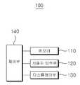
도 6은 본 발명의 다른 실시예인 시뮬레이션 시스템의 전자적인 구성을 설명하기 위한 블록 구성도이다. 도 6에 도시된 바와 같이, 본 발명의 일실시예인 시뮬레이션 시스템(100)은, 메모리(110), 사용자 입력부(120), 디스플레이부(130) 및 제어부(140)를 포함하여 구성될 수 있다.6 is a block diagram illustrating an electronic configuration of a simulation system according to another embodiment of the present invention. 6, the
메모리(110)는 오브젝트간의 벡터 거리를 측정하는 오브젝트 거리 측정 프로그램이 저장되는 구성요소이다. 이러한 메모리(110)는 플래시 메모리 타입(flash memory type), 하드디스크 타입(hard disk type), 멀티미디어 카드 마이크로 타입(multimedia card micro type), 카드 타입의 메모리(예를 들어 SD 또는 XD 메모리 등), 램(Random Access Memory, RAM), SRAM(Static Random Access Memory), 롬(Read-Only Memory, ROM), EEPROM(Electrically Erasable Programmable Read-Only Memory), PROM(Programmable Read-Only Memory), 자기 메모리, 자기 디스크, 광디스크 중 적어도 하나의 타입의 저장매체를 포함할 수 있다.The
사용자 입력부(120)는, 상기 제 1 오브젝트에 대한 이동신호를 생성하기 위한 구성요소이다. 이러한 사용자 입력부(120)로는 키버튼, 마우스, 키보드, 터치스크린등이 이용될 수 있다.The
디스플레이부(130)는, 본 발명에 따른 시뮬레이션 시스템의 제어부 처리되는 정보를 표시(출력)한다. 즉, 오브젝트인 치아를 표시하고 이와 관련된 다양한 GUI 및 UI 정보를 표시하기 위한 구성요소이다.The
디스플레이부(130)는 액정 디스플레이(liquid crystal display, LCD), 박막 트랜지스터 액정 디스플레이(thin film transistor-liquid crystal display, TFT LCD), 유기 발광 다이오드(organic light-emitting diode, OLED), 플렉시블 디스플레이(flexible display), 3차원 디스플레이(3D display) 중에서 적어도 하나를 포함할 수 있다.The
제어부(140)는 사용자 입력부(120)를 통해 입력된 이동 신호에 기초하여 복수의 오브젝트 중 제 1 오브젝트를 제 1 방향으로 이동시키면, 상기 메모리(110)에 저장된 오브젝트 거리 측정 프로그램을 구동하여 상기 제 1 오브젝트의 이동에 따라 상기 제 1 오브젝트와 상기 제 1 오브젝트의 인접 오브젝트인 상기 제 2 오브젝트의 벡터 거리를 측정하고, 상기 벡터 거리가 기설정 벡터 거리 범위내에 있도록 상기 제 2 오브젝트를 기설정 패스를 따라 제 1 방향으로 소정거리 자동으로 벡터이동시키고 이를 상기 디스플레이부(130)에 표시하는 기능을 한다. 이 제어부의 동작에 대해서는 도 3 내지 도 5에서 상세히 설명하였으므로, 이에 대한 설명은 설명의 간략화를 위하여 생략한다.The
또한, 본 발명의 일실시예에 의하면, 전술한 방법은, 프로그램이 기록된 매체에 프로세서가 읽을 수 있는 코드로서 구현하는 것이 가능하다. 즉, 상술한 치아 교정 시뮬레이션 장치에서의 치아돌출 각도 자동 조절 방법이 저장된 컴퓨터로 판독 가능한 기록 매체에 저장될 수 있다. 프로세서가 읽을 수 있는 매체의 예로는, ROM, RAM, CD-ROM, 자기 테이프, 플로피 디스크, 광 데이터 저장장치 등이 있으며, 캐리어 웨이브(예를 들어, 인터넷을 통한 전송)의 형태로 구현되는 것도 포함한다.Further, according to an embodiment of the present invention, the above-described method can be implemented as a code that can be read by a processor on a medium on which the program is recorded. That is, the method of automatically adjusting the tooth protrusion angle in the above-described orthodontic appliance can be stored in a computer-readable recording medium. Examples of the medium that can be read by the processor include ROM, RAM, CD-ROM, magnetic tape, floppy disk, optical data storage, etc., and may be implemented in the form of a carrier wave (e.g., transmission over the Internet) .
상술한 구성을 가지는 본 발명의 일실시예에 따르면, 오브젝트를 하나 이동하게 되면, 사용자의 의사를 고려하여, 인접한 오브젝트가 자동으로 정렬되기 때문에 사용자 편의성을 높일 수 있게 된다.According to an embodiment of the present invention having the above-described configuration, when one object is moved, the neighboring objects are automatically aligned in consideration of the intention of the user, thereby enhancing user convenience.
상기와 같이 설명된 시뮬레이션 시스템에서의 오브젝트 자동 이동 방법 및 이를 적용한 시뮬레이션 시스템은 상기 설명된 실시 예들의 구성과 방법이 한정되게 적용될 수 있는 것이 아니라, 상기 실시 예들의 다양한 변형이 이루어질 수 있도록 각 실시 예들의 전부 또는 일부가 선택적으로 조합되어 구성될 수도 있다.
The method and apparatus for automatically moving an object in the simulation system described above and the simulation system using the same are not limited to the configuration and method of the embodiments described above, All or a part of the above-described elements may be selectively combined.
100 : 시뮬레이션 시스템
110 : 메모리
120 : 사용자 입력부
130 : 디스플레이부
140 : 제어부100: Simulation system
110: Memory
120: user input section
130:
140:
Claims (15)
Translated fromKorean상기 제 1 오브젝트의 이동에 따라 상기 제 1 오브젝트와 상기 제 1 오브젝트의 인접 오브젝트인 제 2 오브젝트의 벡터 거리를 측정하는 단계; 및
상기 벡터 거리가 기설정 벡터 거리 범위내에 있도록 상기 제 2 오브젝트를 기설정 패스를 따라 제 1 방향으로 소정거리 자동으로 벡터이동시키는 단계를 포함하는, 시뮬레이션 시스템에서의 오브젝트 자동 이동 방법.
Moving a first one of the plurality of objects in a first direction;
Measuring a vector distance between the first object and a second object that is a neighbor object of the first object according to the movement of the first object; And
And automatically vectoring the second object a predetermined distance in a first direction along a predetermined path so that the vector distance is within a predetermined vector distance range.
상기 벡터 거리가 기설정 범위내에 있도록 상기 제 2 오브젝트를 기설정 패스를 따라 소정거리 자동 이동시키는 단계는,
상기 벡터 거리가 마이너스값이면, 상기 제 1 오브젝트와 상기 제 2 오브젝트가 중첩되어 있다고 판단하여, 상기 제 1 오브젝트와 상기 제 2 오브젝트가 기설정 범위에 있도록 하기 위하여 상기 제 2 오브젝트를 상기 제 1 오브젝트의 이동 방향에 따라 분리 벡터이동시키는 단계를 포함하는, 시뮬레이션 시스템에서의 오브젝트 자동 이동 방법.
The method according to claim 1,
The step of automatically moving the second object a predetermined distance along the predetermined path so that the vector distance is within the predetermined range,
And determines that the first object and the second object overlap with each other if the vector distance is a negative value and determines that the first object and the second object overlap each other if the vector distance is a minus value, And moving the separation vector according to a moving direction of the object.
상기 벡터 거리가 기설정 범위내에 있도록 상기 제 2 오브젝트를 기설정 패스를 따라 소정거리 자동 이동시키는 단계는,
상기 벡터 거리가 플러스값이면, 상기 제 1 오브젝트와 상기 제 2 오브젝트가 이격되어 있다고 판단하여, 상기 제 1 오브젝트와 상기 제 2 오브젝트가 기설정 벡터 거리 범위에 있도록 하기 위하여 상기 제 2 오브젝트를 상기 제 1 오브젝트의 이동 방향에 따라 인접 벡터이동시키는 단계를 포함하는, 시뮬레이션 시스템에서의 오브젝트 자동 이동 방법.
The method according to claim 1,
The step of automatically moving the second object a predetermined distance along the predetermined path so that the vector distance is within the predetermined range,
The first object and the second object are determined to be spaced apart from each other if the vector distance is a positive value, 1. A method for automatically moving an object in a simulation system, comprising moving an adjacent vector according to a moving direction of the object.
상기 제 2 오브젝트의 자동이동에 따라 제 2 오브젝트의 인접 오브젝트인 제 3 오브젝트를 제 2 오브젝트와 상기 기설정 벡터 거리 범위에 있도록 제 3 오브젝트를 자동이동시키는 단계를 더 포함하는, 시뮬레이션 시스템에서의 오브젝트 자동 이동 방법.
The method according to claim 1,
Further comprising automatically moving a third object such that a third object, which is a neighbor object of the second object, is within a predetermined vector distance range with the second object in accordance with the automatic movement of the second object, Automatic moving method.
상기 벡터 거리가 기설정 벡터 거리 범위내에 있도록 상기 제 2 오브젝트를 기설정 패스를 따라 제 1 방향으로 소정거리 자동으로 벡터이동시키는 단계는,
상기 제 2 오브젝트에서 제 1 제어점 및 제 2 제어점을 결정하는 단계; 및
상기 제 1 제어점 및 상기 제 2 제어점이 상기 기설정 패스에 매칭되도록 하면서 상기 제 2 오브젝트를 벡터이동시키는 단계를 포함하는, 시뮬레이션 시스템에서의 오브젝트 자동 이동 방법.
The method according to claim 1,
The step of automatically vector-aligning the second object by a predetermined distance in the first direction along the predetermined path so that the vector distance is within the predetermined vector distance range,
Determining a first control point and a second control point in the second object; And
And vector moving the second object while allowing the first control point and the second control point to match the preset path.
상기 벡터 거리가 기설정 벡터 거리 범위내에 있도록 상기 제 2 오브젝트를 기설정 패스를 따라 제 1 방향으로 소정거리 자동 벡터 이동시키는 단계는,
상기 제 2 오브젝트를 상기 기설정 벡터 거리보다 작은 기준 거리를 반복이동시키는 단계를 더 포함하는, 시뮬레이션 시스템에서의 오브젝트 자동 이동 방법.
The method according to claim 1,
The step of moving the second object by a predetermined distance in a first direction along the preset path such that the vector distance is within the predetermined vector distance range,
Further comprising the step of repeatedly moving the second object to a reference distance smaller than the predetermined vector distance.
복수의 오브젝트 중 제 1 오브젝트를 제 1 방향으로 이동시키는 단계는,
상기 제 1 오브젝트를 제 1 위치에서 제 2 위치로 이동시키는 단계를 포함하고,
상기 벡터 거리가 기설정 벡터 거리 범위내에 있도록 상기 제 2 오브젝트를 기설정 패스를 따라 제 1 방향으로 소정거리 자동 벡터 이동시키는 단계는,
상기 제 1 오브젝트와 상기 제 2 오브젝트 각각의 중심점을 제어점으로 결정하는 단계;
상기 제어점들 사이의 벡터 방향을 결정하는 단계; 및
상기 벡터 방향으로 상기 기설정 벡터 거리보다 작은 기준 거리 만큼 상기 제 2 오브젝트를 직선 이동시키는 단계를 포함하는, 시뮬레이션 시스템에서의 오브젝트 자동 이동 방법.
The method according to claim 1,
Wherein moving the first one of the plurality of objects in the first direction comprises:
Moving the first object from a first position to a second position,
The step of moving the second object by a predetermined distance in a first direction along the preset path such that the vector distance is within the predetermined vector distance range,
Determining a center point of each of the first object and the second object as control points;
Determining a vector direction between the control points; And
And linearly moving the second object by a reference distance smaller than the predetermined vector distance in the vector direction.
상기 벡터 거리가 기설정 벡터 거리 범위내에 있도록 상기 제 2 오브젝트를 기설정 패스를 따라 제 1 방향으로 소정거리 자동 벡터 이동시키는 단계는,
상기 제 2 오브젝트를 기설정 패스를 따라 제 1 방향으로 소정거리 아치 이동시키는 단계를 포함하는, 시뮬레이션 시스템에서의 오브젝트 자동 이동 방법.
The method according to claim 1,
The step of moving the second object by a predetermined distance in a first direction along the preset path such that the vector distance is within the predetermined vector distance range,
And moving the second object by a predetermined distance in a first direction along a predetermined path in a first direction.
상기 복수의 오브젝트는 3D 오브젝트인, 시뮬레이션 시스템에서의 오브젝트 자동 이동 방법.
The method according to claim 1,
Wherein the plurality of objects are 3D objects.
복수의 상기 3D 오브젝트과 평면방정식을 가진 기준면이 교차하는 교차점을 추출하는 단계;
상기 교차점을 이용하여 상기 3D 오브젝트를 2D 오브젝트로 전환하는 단계; 및
상기 2D 오브젝트의 중심점을 이용하여 결정된 2D 패스를 상기 기설정 패스로 설정하는 단계를 포함하는, 시뮬레이션 시스템에서의 오브젝트 자동 이동 방법.
10. The method of claim 9,
Extracting an intersection where a plurality of the 3D objects and a reference plane having a plane equation intersect with each other;
Converting the 3D object into a 2D object using the intersection; And
And setting the 2D path determined using the center point of the 2D object as the default path.
상기 제 1 오브젝트의 이동에 따라 상기 제 1 오브젝트와 상기 제 1 오브젝트의 인접 오브젝트인 상기 제 2 오브젝트의 벡터 거리를 측정하는 단계는,
상기 기설정 패스를 기준으로 상기 제 1 오브젝트의 포인트와 상기 제 2 오브젝트의 포인트간의 최단거리를 계산하여, 상기 벡터 거리를 획득하는 단계를 포함하는, 시뮬레이션 시스템에서의 오브젝트 자동 이동 방법.
The method according to claim 1,
Wherein the step of measuring the vector distance of the second object, which is a neighbor object of the first object and the first object, according to the movement of the first object,
Calculating a shortest distance between a point of the first object and a point of the second object based on the preset path to obtain the vector distance.
상기 제 1 오브젝트의 이동에 따라 상기 제 1 오브젝트와 상기 제 1 오브젝트의 인접 오브젝트인 상기 제 2 오브젝트의 벡터 거리를 측정하는 단계는,
상기 기설정 패스를 기준으로 상기 제 1 오브젝트의 포인트와 상기 제 2 오브젝트의 면과의 최단거리를 계산하여, 상기 벡터 거리를 획득하는 단계를 포함하는, 시뮬레이션 시스템에서의 오브젝트 자동 이동 방법.
The method according to claim 1,
Wherein the step of measuring the vector distance of the second object, which is a neighbor object of the first object and the first object, according to the movement of the first object,
Calculating a shortest distance between a point of the first object and a face of the second object based on the preset path to obtain the vector distance.
상기 제 1 오브젝트 및 상기 제 2 오브젝트의 포인트의 수를 기초로 하여 레벨링하는 단계;
사용자 입력 신호에 의해 결정된 레벨에 따라 상기 제 1 오브젝트의 포인트와 상기 제 2 오브젝트의 포인트간의 거리를 계산하여, 상기 최단 거리를 계산하는 단계를 더 포함하는, 시뮬레이션 시스템에서의 오브젝트 자동 이동 방법.
12. The method of claim 11,
Leveling based on the number of points of the first object and the second object;
Further comprising calculating a distance between a point of the first object and a point of the second object according to a level determined by the user input signal to calculate the shortest distance.
오브젝트간의 벡터 거리를 측정하는 오브젝트 거리 측정 프로그램이 저장된 메모리;
제 1 오브젝트에 대하여 이동신호를 생성하기 위한 사용자 입력부; 및
상기 사용자 입력부를 통해 입력된 이동 신호에 기초하여 복수의 오브젝트 중 제 1 오브젝트를 제 1 방향으로 이동시키면, 상기 메모리에 저장된 오브젝트 거리 측정 프로그램을 구동하여 상기 제 1 오브젝트의 이동에 따라 상기 제 1 오브젝트와 상기 제 1 오브젝트의 인접 오브젝트인 제 2 오브젝트의 벡터 거리를 측정하고, 상기 벡터 거리가 기설정 벡터 거리 범위내에 있도록 상기 제 2 오브젝트를 기설정 패스를 따라 제 1 방향으로 소정거리 자동으로 벡터이동시키고 이를 상기 디스플레이부에 표시하는 제어부를 포함하는, 시뮬레이션 시스템.
A display unit for displaying a plurality of objects;
A memory for storing an object distance measurement program for measuring a vector distance between objects;
A user input for generating a movement signal for the first object; And
Wherein when the first object among the plurality of objects is moved in the first direction based on the movement signal input through the user input unit, the object distance measurement program stored in the memory is driven to move the first object And a vector distance of a second object that is a neighbor object of the first object is measured and the second object is automatically vector-shifted by a predetermined distance in the first direction along the predetermined path so that the vector distance is within the predetermined vector distance range And displaying it on the display unit.
Priority Applications (4)
| Application Number | Priority Date | Filing Date | Title |
|---|---|---|---|
| KR1020140178446AKR101651629B1 (en) | 2014-12-11 | 2014-12-11 | Method for automatically moving object in simulation system and simulation system applying the same |
| US15/535,048US10478269B2 (en) | 2014-12-11 | 2015-07-07 | Method for automatically moving object in simulation system and simulation system using the same |
| PCT/KR2015/007012WO2016093455A1 (en) | 2014-12-11 | 2015-07-07 | Automatic object movement method in simulation system, and simulation system using same |
| CN201580067792.7ACN107106259B (en) | 2014-12-11 | 2015-07-07 | Object automatic moving method in simulation system and simulation system using the same |
Applications Claiming Priority (1)
| Application Number | Priority Date | Filing Date | Title |
|---|---|---|---|
| KR1020140178446AKR101651629B1 (en) | 2014-12-11 | 2014-12-11 | Method for automatically moving object in simulation system and simulation system applying the same |
Publications (2)
| Publication Number | Publication Date |
|---|---|
| KR20160071127A KR20160071127A (en) | 2016-06-21 |
| KR101651629B1true KR101651629B1 (en) | 2016-09-05 |
Family
ID=56107610
Family Applications (1)
| Application Number | Title | Priority Date | Filing Date |
|---|---|---|---|
| KR1020140178446AActiveKR101651629B1 (en) | 2014-12-11 | 2014-12-11 | Method for automatically moving object in simulation system and simulation system applying the same |
Country Status (4)
| Country | Link |
|---|---|
| US (1) | US10478269B2 (en) |
| KR (1) | KR101651629B1 (en) |
| CN (1) | CN107106259B (en) |
| WO (1) | WO2016093455A1 (en) |
Families Citing this family (52)
| Publication number | Priority date | Publication date | Assignee | Title |
|---|---|---|---|---|
| US10772506B2 (en) | 2014-07-07 | 2020-09-15 | Align Technology, Inc. | Apparatus for dental confocal imaging |
| US9675430B2 (en) | 2014-08-15 | 2017-06-13 | Align Technology, Inc. | Confocal imaging apparatus with curved focal surface |
| US10449016B2 (en) | 2014-09-19 | 2019-10-22 | Align Technology, Inc. | Arch adjustment appliance |
| US9610141B2 (en) | 2014-09-19 | 2017-04-04 | Align Technology, Inc. | Arch expanding appliance |
| US9744001B2 (en) | 2014-11-13 | 2017-08-29 | Align Technology, Inc. | Dental appliance with cavity for an unerupted or erupting tooth |
| US10504386B2 (en) | 2015-01-27 | 2019-12-10 | Align Technology, Inc. | Training method and system for oral-cavity-imaging-and-modeling equipment |
| US10248883B2 (en) | 2015-08-20 | 2019-04-02 | Align Technology, Inc. | Photograph-based assessment of dental treatments and procedures |
| US11931222B2 (en) | 2015-11-12 | 2024-03-19 | Align Technology, Inc. | Dental attachment formation structures |
| US11554000B2 (en) | 2015-11-12 | 2023-01-17 | Align Technology, Inc. | Dental attachment formation structure |
| US11103330B2 (en) | 2015-12-09 | 2021-08-31 | Align Technology, Inc. | Dental attachment placement structure |
| US11596502B2 (en) | 2015-12-09 | 2023-03-07 | Align Technology, Inc. | Dental attachment placement structure |
| US10383705B2 (en) | 2016-06-17 | 2019-08-20 | Align Technology, Inc. | Orthodontic appliance performance monitor |
| WO2017218947A1 (en) | 2016-06-17 | 2017-12-21 | Align Technology, Inc. | Intraoral appliances with sensing |
| US10507087B2 (en) | 2016-07-27 | 2019-12-17 | Align Technology, Inc. | Methods and apparatuses for forming a three-dimensional volumetric model of a subject's teeth |
| CA3030676A1 (en) | 2016-07-27 | 2018-02-01 | Align Technology, Inc. | Intraoral scanner with dental diagnostics capabilities |
| US11058524B2 (en)* | 2016-09-26 | 2021-07-13 | James R. Glidewell Dental Ceramics, Inc. | Dental restoration design tools |
| CN117257492A (en) | 2016-11-04 | 2023-12-22 | 阿莱恩技术有限公司 | Method and apparatus for dental imaging |
| AU2017366755B2 (en) | 2016-12-02 | 2022-07-28 | Align Technology, Inc. | Methods and apparatuses for customizing rapid palatal expanders using digital models |
| EP3547952B1 (en) | 2016-12-02 | 2020-11-04 | Align Technology, Inc. | Palatal expander |
| WO2018102770A1 (en) | 2016-12-02 | 2018-06-07 | Align Technology, Inc. | Force control, stop mechanism, regulating structure of removable arch adjustment appliance |
| US10548700B2 (en) | 2016-12-16 | 2020-02-04 | Align Technology, Inc. | Dental appliance etch template |
| CN108268673B (en)* | 2016-12-30 | 2022-08-16 | 无锡时代天使医疗器械科技有限公司 | Method for digitally simulating orthodontic effect of orthodontic device |
| US10456043B2 (en) | 2017-01-12 | 2019-10-29 | Align Technology, Inc. | Compact confocal dental scanning apparatus |
| US10779718B2 (en) | 2017-02-13 | 2020-09-22 | Align Technology, Inc. | Cheek retractor and mobile device holder |
| WO2018183358A1 (en)* | 2017-03-27 | 2018-10-04 | Align Technology, Inc. | Apparatuses and methods assisting in dental therapies |
| US10613515B2 (en) | 2017-03-31 | 2020-04-07 | Align Technology, Inc. | Orthodontic appliances including at least partially un-erupted teeth and method of forming them |
| US11045283B2 (en) | 2017-06-09 | 2021-06-29 | Align Technology, Inc. | Palatal expander with skeletal anchorage devices |
| CN116942335A (en) | 2017-06-16 | 2023-10-27 | 阿莱恩技术有限公司 | Automatic detection of tooth type and eruption status |
| US10639134B2 (en) | 2017-06-26 | 2020-05-05 | Align Technology, Inc. | Biosensor performance indicator for intraoral appliances |
| US10885521B2 (en) | 2017-07-17 | 2021-01-05 | Align Technology, Inc. | Method and apparatuses for interactive ordering of dental aligners |
| CN111107806B (en) | 2017-07-21 | 2022-04-19 | 阿莱恩技术有限公司 | Jaw profile anchoring |
| CN110996842B (en) | 2017-07-27 | 2022-10-14 | 阿莱恩技术有限公司 | Tooth Staining, Transparency and Glazing |
| EP4278957A3 (en) | 2017-07-27 | 2024-01-24 | Align Technology, Inc. | System and methods for processing an orthodontic aligner by means of an optical coherence tomography |
| US12274597B2 (en) | 2017-08-11 | 2025-04-15 | Align Technology, Inc. | Dental attachment template tray systems |
| US11116605B2 (en) | 2017-08-15 | 2021-09-14 | Align Technology, Inc. | Buccal corridor assessment and computation |
| US11123156B2 (en) | 2017-08-17 | 2021-09-21 | Align Technology, Inc. | Dental appliance compliance monitoring |
| US12171575B2 (en) | 2017-10-04 | 2024-12-24 | Align Technology, Inc. | Intraoral systems and methods for sampling soft-tissue |
| US10813720B2 (en) | 2017-10-05 | 2020-10-27 | Align Technology, Inc. | Interproximal reduction templates |
| CN111565668B (en) | 2017-10-27 | 2022-06-07 | 阿莱恩技术有限公司 | Substitute occlusion adjusting structure |
| CN111295153B (en) | 2017-10-31 | 2023-06-16 | 阿莱恩技术有限公司 | Dental appliance with selective bite loading and controlled tip staggering |
| CN119235481A (en) | 2017-11-01 | 2025-01-03 | 阿莱恩技术有限公司 | Automatic treatment planning |
| US11534974B2 (en) | 2017-11-17 | 2022-12-27 | Align Technology, Inc. | Customized fabrication of orthodontic retainers based on patient anatomy |
| US11219506B2 (en) | 2017-11-30 | 2022-01-11 | Align Technology, Inc. | Sensors for monitoring oral appliances |
| US11432908B2 (en) | 2017-12-15 | 2022-09-06 | Align Technology, Inc. | Closed loop adaptive orthodontic treatment methods and apparatuses |
| US10980613B2 (en) | 2017-12-29 | 2021-04-20 | Align Technology, Inc. | Augmented reality enhancements for dental practitioners |
| US10813727B2 (en) | 2018-01-26 | 2020-10-27 | Align Technology, Inc. | Diagnostic intraoral tracking |
| US11937991B2 (en) | 2018-03-27 | 2024-03-26 | Align Technology, Inc. | Dental attachment placement structure |
| EP3773320B1 (en) | 2018-04-11 | 2024-05-15 | Align Technology, Inc. | Releasable palatal expanders |
| KR102097070B1 (en)* | 2018-07-16 | 2020-04-03 | 김정일 | Method for automatic generating orthodontic data |
| GB2585699A (en)* | 2019-07-12 | 2021-01-20 | Tooth Fairy Healthcare Ltd | Remote dentist consultation methods and systems |
| CN111281579B (en)* | 2020-02-27 | 2021-05-07 | 上海正雅齿科科技股份有限公司 | Linkage tooth arrangement method and device, electronic equipment and computer storage medium |
| US20230380935A1 (en)* | 2020-10-28 | 2023-11-30 | Medit Corp. | Data processing method and data processing device |
Citations (3)
| Publication number | Priority date | Publication date | Assignee | Title |
|---|---|---|---|---|
| KR101138354B1 (en) | 2011-06-16 | 2012-04-26 | 김태원 | System providing align teeth data |
| JP2012096427A (en) | 2010-11-01 | 2012-05-24 | Keyence Corp | Apparatus, method and program for generating setting data for three dimensional molding apparatus, and recording medium readable by computer |
| KR101218388B1 (en) | 2011-11-25 | 2013-01-03 | 김태원 | Device providing align teeth data |
Family Cites Families (16)
| Publication number | Priority date | Publication date | Assignee | Title |
|---|---|---|---|---|
| JPH03105568A (en) | 1989-09-20 | 1991-05-02 | Hitachi Ltd | 2-dimensional/3-dimensional unified cad system |
| US5431562A (en)* | 1990-01-19 | 1995-07-11 | Ormco Corporation | Method and apparatus for designing and forming a custom orthodontic appliance and for the straightening of teeth therewith |
| US5602891A (en)* | 1995-11-13 | 1997-02-11 | Beth Israel | Imaging apparatus and method with compensation for object motion |
| US5975893A (en)* | 1997-06-20 | 1999-11-02 | Align Technology, Inc. | Method and system for incrementally moving teeth |
| US6744914B1 (en)* | 2000-04-28 | 2004-06-01 | Orametrix, Inc. | Method and system for generating a three-dimensional object |
| US6648640B2 (en)* | 1999-11-30 | 2003-11-18 | Ora Metrix, Inc. | Interactive orthodontic care system based on intra-oral scanning of teeth |
| KR20090115884A (en) | 2001-10-31 | 2009-11-09 | 이마그노시스 가부시키가이샤 | Medical simulation device |
| US8251699B2 (en)* | 2002-12-31 | 2012-08-28 | Brian C. Reising | Orthodontic bracket and method of attaching orthodontic brackets to teeth |
| KR100583183B1 (en)* | 2004-02-19 | 2006-05-25 | 차경석 | How to provide orthodontic data |
| EP2079394B1 (en)* | 2006-10-27 | 2016-05-18 | Nobel Biocare Services AG | Method and apparatus for obtaining data for a dental component and a physical dental model |
| JP4806338B2 (en) | 2006-12-05 | 2011-11-02 | 富士通株式会社 | CAD apparatus and CAD program |
| GB0706048D0 (en)* | 2007-03-28 | 2007-05-09 | Unilever Plc | A method and apparatus for generating a model of an object |
| CN101604456A (en)* | 2009-07-03 | 2009-12-16 | 西安市恒惠科技有限公司 | Tooth shifter in the area of computer aided orthodontic |
| KR101413222B1 (en) | 2011-10-25 | 2014-06-30 | (주)쓰리디아이티 | An image matching data creation method for orthodontics and remote mock treatment method and providing the information for orthodontics device using the same |
| EP2874562B1 (en)* | 2012-07-18 | 2019-12-18 | Bruno Spindler | Abutment screw |
| CN103932807B (en)* | 2013-01-18 | 2016-10-05 | 无锡时代天使医疗器械科技有限公司 | Obtain tooth target and rescue the method for state, dental appliance manufacture method and dental appliance |
- 2014
- 2014-12-11KRKR1020140178446Apatent/KR101651629B1/enactiveActive
- 2015
- 2015-07-07USUS15/535,048patent/US10478269B2/enactiveActive
- 2015-07-07CNCN201580067792.7Apatent/CN107106259B/ennot_activeExpired - Fee Related
- 2015-07-07WOPCT/KR2015/007012patent/WO2016093455A1/enactiveApplication Filing
Patent Citations (3)
| Publication number | Priority date | Publication date | Assignee | Title |
|---|---|---|---|---|
| JP2012096427A (en) | 2010-11-01 | 2012-05-24 | Keyence Corp | Apparatus, method and program for generating setting data for three dimensional molding apparatus, and recording medium readable by computer |
| KR101138354B1 (en) | 2011-06-16 | 2012-04-26 | 김태원 | System providing align teeth data |
| KR101218388B1 (en) | 2011-11-25 | 2013-01-03 | 김태원 | Device providing align teeth data |
Also Published As
| Publication number | Publication date |
|---|---|
| CN107106259B (en) | 2020-05-29 |
| WO2016093455A1 (en) | 2016-06-16 |
| US10478269B2 (en) | 2019-11-19 |
| KR20160071127A (en) | 2016-06-21 |
| US20170348071A1 (en) | 2017-12-07 |
| CN107106259A (en) | 2017-08-29 |
Similar Documents
| Publication | Publication Date | Title |
|---|---|---|
| KR101651629B1 (en) | Method for automatically moving object in simulation system and simulation system applying the same | |
| JP6760957B2 (en) | 3D modeling method and equipment | |
| JP6210823B2 (en) | Slope stability calculation device, calculation method, and program | |
| US10249052B2 (en) | Stereo correspondence model fitting | |
| EP2974690A1 (en) | Program for design of dental prostheses, device for design of dental prostheses, and method for design of dental prostheses | |
| CN105184855B (en) | Characteristic face construction method based on three-dimensional point cloud and device | |
| JP2016530581A5 (en) | ||
| WO2020117613A1 (en) | Gpu calculation of signed distance fields | |
| CN104908038A (en) | Robot simulation system which simulates takeout process of workpieces | |
| Yamanaka et al. | Modeling the steering time difference between narrowing and widening tunnels | |
| US20160171761A1 (en) | Computing device and method for patching point clouds of object | |
| US20150030253A1 (en) | Electronic device and method for measuring point cloud of an object | |
| CN111951348B (en) | Method and device for determining frame selection area and electronic equipment | |
| JP2021088028A (en) | Display device and display program | |
| JP2015184061A (en) | Extracting device, method, and program | |
| KR102377626B1 (en) | System of processing X-ray image and method of using the same | |
| CN103424070A (en) | Curved face coordinate system set-up system and method | |
| CN108762527A (en) | A kind of recognition positioning method and device | |
| JP2012256270A5 (en) | ||
| CN108646932B (en) | Vibration detection method and device for electronic equipment and electronic equipment | |
| US9761046B2 (en) | Computing device and simulation method for processing an object | |
| CN103217147B (en) | Measuring equipment and measuring method | |
| CN109885369A (en) | Image interlock method and device | |
| CN106406702B (en) | A kind of image display method and device | |
| JP2017142547A (en) | Three-dimensional model generation device, three-dimensional model generation method, and program |
Legal Events
| Date | Code | Title | Description |
|---|---|---|---|
| A201 | Request for examination | ||
| PA0109 | Patent application | Patent event code:PA01091R01D Comment text:Patent Application Patent event date:20141211 | |
| PA0201 | Request for examination | ||
| E902 | Notification of reason for refusal | ||
| PE0902 | Notice of grounds for rejection | Comment text:Notification of reason for refusal Patent event date:20160322 Patent event code:PE09021S01D | |
| E701 | Decision to grant or registration of patent right | ||
| PE0701 | Decision of registration | Patent event code:PE07011S01D Comment text:Decision to Grant Registration Patent event date:20160530 | |
| PG1501 | Laying open of application | ||
| GRNT | Written decision to grant | ||
| PR0701 | Registration of establishment | Comment text:Registration of Establishment Patent event date:20160822 Patent event code:PR07011E01D | |
| PR1002 | Payment of registration fee | Payment date:20160823 End annual number:3 Start annual number:1 | |
| PG1601 | Publication of registration | ||
| FPAY | Annual fee payment | Payment date:20190814 Year of fee payment:4 | |
| PR1001 | Payment of annual fee | Payment date:20190814 Start annual number:4 End annual number:4 | |
| PR1001 | Payment of annual fee | Payment date:20210818 Start annual number:6 End annual number:6 | |
| PR1001 | Payment of annual fee | Payment date:20220804 Start annual number:7 End annual number:7 | |
| PR1001 | Payment of annual fee | Payment date:20230822 Start annual number:8 End annual number:8 | |
| PR1001 | Payment of annual fee | Payment date:20240821 Start annual number:9 End annual number:9 |