KR101651033B1 - Terminal and operating method thereof - Google Patents
Terminal and operating method thereofDownload PDFInfo
- Publication number
- KR101651033B1 KR101651033B1KR1020150002968AKR20150002968AKR101651033B1KR 101651033 B1KR101651033 B1KR 101651033B1KR 1020150002968 AKR1020150002968 AKR 1020150002968AKR 20150002968 AKR20150002968 AKR 20150002968AKR 101651033 B1KR101651033 B1KR 101651033B1
- Authority
- KR
- South Korea
- Prior art keywords
- terminal
- state
- case
- cover state
- cover
- Prior art date
- Legal status (The legal status is an assumption and is not a legal conclusion. Google has not performed a legal analysis and makes no representation as to the accuracy of the status listed.)
- Expired - Fee Related
Links
Images


Classifications
- H—ELECTRICITY
- H04—ELECTRIC COMMUNICATION TECHNIQUE
- H04M—TELEPHONIC COMMUNICATION
- H04M1/00—Substation equipment, e.g. for use by subscribers
- H04M1/72—Mobile telephones; Cordless telephones, i.e. devices for establishing wireless links to base stations without route selection
- H04M1/724—User interfaces specially adapted for cordless or mobile telephones
- H04M1/72448—User interfaces specially adapted for cordless or mobile telephones with means for adapting the functionality of the device according to specific conditions
- H04M1/7246—User interfaces specially adapted for cordless or mobile telephones with means for adapting the functionality of the device according to specific conditions by connection of exchangeable housing parts
- H—ELECTRICITY
- H04—ELECTRIC COMMUNICATION TECHNIQUE
- H04M—TELEPHONIC COMMUNICATION
- H04M1/00—Substation equipment, e.g. for use by subscribers
- H04M1/02—Constructional features of telephone sets
- H04M1/0202—Portable telephone sets, e.g. cordless phones, mobile phones or bar type handsets
- H04M1/0206—Portable telephones comprising a plurality of mechanically joined movable body parts, e.g. hinged housings
- H04M1/0241—Portable telephones comprising a plurality of mechanically joined movable body parts, e.g. hinged housings using relative motion of the body parts to change the operational status of the telephone set, e.g. switching on/off, answering incoming call
- H04M1/0245—Portable telephones comprising a plurality of mechanically joined movable body parts, e.g. hinged housings using relative motion of the body parts to change the operational status of the telephone set, e.g. switching on/off, answering incoming call using open/close detection
- H—ELECTRICITY
- H04—ELECTRIC COMMUNICATION TECHNIQUE
- H04B—TRANSMISSION
- H04B1/00—Details of transmission systems, not covered by a single one of groups H04B3/00 - H04B13/00; Details of transmission systems not characterised by the medium used for transmission
- H04B1/38—Transceivers, i.e. devices in which transmitter and receiver form a structural unit and in which at least one part is used for functions of transmitting and receiving
- H04B1/3827—Portable transceivers
- H04B1/3888—Arrangements for carrying or protecting transceivers
- H—ELECTRICITY
- H04—ELECTRIC COMMUNICATION TECHNIQUE
- H04M—TELEPHONIC COMMUNICATION
- H04M1/00—Substation equipment, e.g. for use by subscribers
- H04M1/72—Mobile telephones; Cordless telephones, i.e. devices for establishing wireless links to base stations without route selection
- H04M1/724—User interfaces specially adapted for cordless or mobile telephones
- H04M1/72403—User interfaces specially adapted for cordless or mobile telephones with means for local support of applications that increase the functionality
- H04M1/72409—User interfaces specially adapted for cordless or mobile telephones with means for local support of applications that increase the functionality by interfacing with external accessories
- H04M1/724092—Interfacing with an external cover providing additional functionalities
- H—ELECTRICITY
- H04—ELECTRIC COMMUNICATION TECHNIQUE
- H04M—TELEPHONIC COMMUNICATION
- H04M1/00—Substation equipment, e.g. for use by subscribers
- H04M1/72—Mobile telephones; Cordless telephones, i.e. devices for establishing wireless links to base stations without route selection
- H04M1/724—User interfaces specially adapted for cordless or mobile telephones
- H04M1/72448—User interfaces specially adapted for cordless or mobile telephones with means for adapting the functionality of the device according to specific conditions
- H04M1/72563—
- H—ELECTRICITY
- H04—ELECTRIC COMMUNICATION TECHNIQUE
- H04M—TELEPHONIC COMMUNICATION
- H04M1/00—Substation equipment, e.g. for use by subscribers
- H04M1/02—Constructional features of telephone sets
- H04M1/0202—Portable telephone sets, e.g. cordless phones, mobile phones or bar type handsets
- H04M1/0206—Portable telephones comprising a plurality of mechanically joined movable body parts, e.g. hinged housings
- H04M1/0208—Portable telephones comprising a plurality of mechanically joined movable body parts, e.g. hinged housings characterized by the relative motions of the body parts
- H04M1/0214—Foldable telephones, i.e. with body parts pivoting to an open position around an axis parallel to the plane they define in closed position
- H—ELECTRICITY
- H04—ELECTRIC COMMUNICATION TECHNIQUE
- H04M—TELEPHONIC COMMUNICATION
- H04M2250/00—Details of telephonic subscriber devices
- H04M2250/12—Details of telephonic subscriber devices including a sensor for measuring a physical value, e.g. temperature or motion
Landscapes
- Engineering & Computer Science (AREA)
- Signal Processing (AREA)
- Computer Networks & Wireless Communication (AREA)
- Human Computer Interaction (AREA)
- Telephone Function (AREA)
- User Interface Of Digital Computer (AREA)
Abstract
Translated fromKoreanDescription
Translated fromKorean본 발명은 단말기 및 그 동작 방법에 관한 것으로, 단말기에 결합된 단말기 케이스의 케이스 상태에 대응하는 동작을 수행하는 단말기에 관한 것이다.The present invention relates to a terminal and an operation method thereof, and more particularly, to a terminal that performs an operation corresponding to a case state of a terminal case coupled to a terminal.
단말기는 이동 가능 여부에 따라 단말기(mobile/portable terminal) 및 고정 단말기(stationary terminal)으로 나뉠 수 있다. 다시 단말기는 사용자의 직접 휴대 가능 여부에 따라 휴대(형) 단말기(handheld terminal) 및 거치형 단말기(vehicle mount terminal)로 나뉠 수 있다.A terminal can be divided into a mobile / portable terminal and a stationary terminal depending on whether the terminal is movable or not. Again, the terminal can be divided into a handheld terminal and a vehicle mount terminal according to whether the user can carry it directly.
이와 같은 단말기(terminal)는 기능이 다양화됨에 따라 예를 들어, 사진이나 동영상의 촬영, 음악이나 동영상 파일의 재생, 게임, 방송의 수신 등의 복합적인 기능들을 갖춘 멀티미디어 기기(Multimedia player) 형태로 구현되고 있다. 그리고 단말기가 멀티미디어 기기 형태로 구현되고 있음에 따라, 단말기에는 이전보다 큰 디스플레이가 구비되고 있는 실정이다. 그리고 단말기의 디스플레이는 두께가 얇고 고해상도이면서, 터치 패널을 포함하기 때문에 단말기의 가격에서 차지하는 비중이 큰 고가의 부품에 해당한다.Such a terminal has various functions, for example, in the form of a multimedia device having multiple functions such as photographing and photographing of a moving picture, reproduction of a music or video file, reception of a game and broadcasting, etc. . Also, since the terminal is implemented in the form of a multimedia device, a terminal has a larger display than before. Since the display of the terminal is thin and high-resolution and includes the touch panel, it corresponds to an expensive component having a large portion of the price of the terminal.
한편, 단말기의 디스플레이가 커짐에 따라, 단말기의 추락, 단말기에 대한 충격 등에 의해 단말기의 디스플레이가 파손되는 일이 잦아지고 있다.On the other hand, as the display of the terminal becomes larger, the display of the terminal often becomes damaged due to a fall of the terminal, an impact on the terminal, and the like.
따라서 사용자들은 이러한 단말기의 디스플레이 파손 위험으로부터 단말기를 보호하기 위하여 다양한 형태의 단말기 케이스를 단말기에 결합하여 사용하고 있다. 특히, 단말기의 디스플레이를 보호하기 위해 단말기의 전면을 단말기 케이스의 케이스 전면이 덮는 형태의 단말기 케이스가 많이 사용되고 있다.Therefore, in order to protect the terminal from the risk of display damage of the terminal, various types of terminal cases are combined with the terminal. Particularly, in order to protect the display of the terminal, a terminal case in which the front surface of the terminal covers the entire surface of the terminal case is often used.
하지만, 케이스 전면이 단말기의 전면을 덮는 형태의 단말기 케이스를 사용하는 경우, 사용자는 단말기를 사용하기 위해 단말기 케이스의 케이스 전면을 젖혀야만 하는 불편함이 있다.However, when using a terminal case in which the front surface of the case covers the front surface of the terminal, the user has to incline the case surface of the terminal case in order to use the terminal.
이에 따라 최근에는 단말기 케이스 사용으로 인한 단말기 사용의 불편함을 해소하기 위해, 단말기는 단말기 케이스와 결합된 단말기가 단말기 케이스의 케이스 전면이 젖혀지는 것을 인식하는 경우에 단말기의 디스플레이가 켜지는 동작을 지원하기도 한다. 또한, 단말기 케이스의 케이스 전면에 단말기의 디스플레이 일부 영역을 확인할 수 있는 창을 구비해서, 단말기의 디스플레이 일부 화면을 사용자가 확인할 수 있도록 하기도 한다.Accordingly, in order to solve the inconvenience of using the terminal due to the use of the terminal case, the terminal supports an operation of turning on the display of the terminal when the terminal combined with the terminal case recognizes that the case surface of the terminal case is being bent It is also said. In addition, a window for confirming a part of the display area of the terminal is provided on the case front surface of the terminal case so that the user can confirm the display partial screen of the terminal.
하지만, 이러한 기능들은 단말기의 일부 동작만을 지원할 뿐이어서, 단말기가 수행할 수 있는 다양한 동작을 제공할 수 없는 불편함이 있다. 또한, 단말기 케이스와 결합된 단말기를 사용하는 사용자가 원하는 동작을 하기 위해, 사용자는 여전히 단말기 케이스의 케이스 전면을 젖힌 후, 몇 번의 입력 단계를 거쳐야 하는 한계가 있다.However, these functions only support some operations of the terminal, and thus inconvenience that various operations that the terminal can perform can not be provided. In addition, in order to perform a desired operation by a user using a terminal combined with the terminal case, the user still has to input a number of input steps after tilting the case front of the terminal case.
따라서, 단말기 케이스와 결합된 단말기를 사용하는 사용자가 원하는 다양한 동작을 단말기 케이스의 상태에 따라 제공할 수 있는 단말기가 필요하다.Accordingly, there is a need for a terminal that can provide various operations desired by a user using a terminal combined with the terminal case according to the state of the terminal case.
본 발명은 단말기와 결합된 단말기 케이스의 상태를 인식하고, 인식된 커버 상태에 대응하는 다양한 동작을 수행하는 단말기를 제공하는데 목적이 있다.It is an object of the present invention to provide a terminal that recognizes the state of the terminal case coupled with the terminal and performs various operations corresponding to the recognized state of the cover.
본 발명의 일 실시 예에 따른 단말기의 동작 방법에 있어서, 단말기의 동작 상태, 상기 단말기 케이스의 상태 중 하나 이상을 포함하는 단말기 상태를 판단하는 단계; 상기 단말기 케이스의 상태 변화를 인식하는 단계; 및 상기 판단된 단말기 상태 및 상기 인식된 단말기 케이스의 상태 변화에 대응하는 동작을 수행하는 단계를 포함하고, 상기 단말기 케이스의 상태는 상기 단말기의 전면을 덮는, 상기 단말기 케이스의 케이스 전면부의 상기 단말기에 대응하는 위치를 포함한다.The method of operating a terminal according to an embodiment of the present invention includes: determining a terminal status including at least one of an operation state of the terminal and a state of the terminal case; Recognizing a change in the state of the terminal case; And performing an operation corresponding to the determined terminal state and a change in the state of the recognized terminal case, wherein the state of the terminal case covers a front surface of the terminal, And corresponding positions.
본 발명의 일 실시 예에 따른 단말기는 디스플레이부; 상기 단말기의 전면을 덮는, 상기 단말기 케이스의 케이스 전면부의 상기 단말기에 대응하는 위치를 센싱하는 센싱부; 및 상기 센싱부의 센싱 결과를 기초로 상기 단말기 케이스의 상태를 판단하고, 상기 단말기의 동작 상태를 판단하고, 상기 판단된 단말기 케이스의 상태를 기초로 상기 단말기 케이스의 상태 변화를 인식하고, 상기 판단된 단말기 상태 및 상기 인식된 단말기 케이스의 상태 변화에 대응하는 동작을 수행하는 제어부를 포함한다.A terminal according to an embodiment of the present invention includes a display unit; A sensing unit for sensing a position of the case front surface of the terminal case, which covers the front surface of the terminal, corresponding to the terminal; Determining a state of the terminal case based on the sensing result of the sensing unit, determining an operation state of the terminal, recognizing a state change of the terminal case based on the determined state of the terminal case, And a controller for performing an operation corresponding to a terminal status and a change in status of the recognized terminal case.
본 발명의 실시 예에 따른 단말기 및 그 동작 방법에 따르면, 단말기는 단말기와 결합된 단말기 케이스의 케이스 상태에 따라 다양한 동작을 수행할 수 있어서, 단말기 케이스를 단말기에 결합하여 사용하는 사용자가 보다 편리하게 단말기를 사용하도록 할 수 있다.According to the terminal and the method of operating the terminal according to the embodiment of the present invention, the terminal can perform various operations according to the case state of the terminal case coupled to the terminal, The terminal can be used.
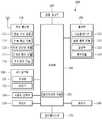
도 1은 본 발명의 일 실시 예와 관련된 단말기의 블록 구성도(block diagram)이다.
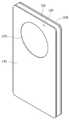
도 2는 본 발명의 일 실시 예에 따른 단말기 케이스를 나타내는 예시도이다.
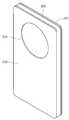
도 3은 본 발명의 일 실시 예에 따른 자성체가 장착된 단말기 케이스를 나타내는 예시도이다.
도 4는 본 발명의 다른 실시 예에 따른 자성체가 장착된 단말기 케이스를 나타내는 예시도이다.
도 5는 본 발명의 일 실시 예에 따른 단말기의 자기 센서를 나타내는 예시도이다.
도 6은 본 발명의 일 실시 예에 따른 복수의 자기 센서를 포함하는 단말기의 단면을 나타내는 단면도이다.
도 7은 본 발명의 일 실시 예에 따른 단말기의 전면 센서를 나타내는 예시도이다.
도 8은 본 발명의 일 실시 예에 따른 단말기의 전면센서의 센싱을 나타내는 예시도이다.
도 9는 본 발명의 일 실시 예에 따른 단말기 케이스와 결합된 단말기를 나타내는 예시도이다.
도 10은 본 발명의 일 실시 예에 따른 단말기의 후면센서의 센싱을 나타내는 예시도이다.
도 11은 본 발명의 일 실시 예에 따른 단말기의 동작 방법을 나타내는 흐름도이다.
도 12는 본 발명의 일 실시 예에 따른 단말기 케이스의 제1 커버 상태를 나타내는 예시도이다.
도 13은 본 발명의 일 실시 예에 따른 단말기 케이스의 제2 커버 상태를 나타내는 예시도이다.
도 14는 본 발명의 일 실시 예에 따른 단말기 케이스의 제3 커버 상태를 나타내는 예시도이다.
도 15는 본 발명의 제1 실시 예에 따른 단말기 동작을 나타내는 흐름도이다.
도 16은 본 발명의 일 실시 예에 따른 제1 커버 상태에서의 단말기 화면 표시를 나타내는 예시도이다.
도 17은 본 발명의 일 실시 예에 따른 전화 수신 화면에 대응하는 제1 동작을 나타내는 예시도이다.
도 18은 본 발명의 일 실시 예에 따른 전화 종료 화면에 대응하는 제1 화면을 나타내는 예시도이다.
도 19는 본 발명의 일 실시 예에 따른 전화 종료 화면에 대응하는 제2 화면을 나타내는 예시도이다.
도 20은 본 발명의 일 실시 예에 따른 전화 수신 화면에 대응하는 제2 동작을 나타내는 예시도이다.
도 21은 본 발명의 일 실시 예에 따른 단말기의 제3 동작에 따른 제2 윈도우 표시에 대한 예시도이다.
도 22는 본 발명의 일 실시 예에 따른 제2 윈도우에 대한 편집 동작을 나타내는 예시도이다.
도 23은 본 발명의 일 실시 예에 따른 제2 윈도우에 따른 이벤트 실행 동작을 나타내는 예시도이다.
도 24는 본 발명의 일 실시 예에 따른 제2 윈도우에 대한 이벤트 추가 동작을 나타내는 예시도이다.
도 25는 본 발명의 제2 실시 예에 따른 단말기 동작을 나타내는 흐름도이다.
도 26은 본 발명의 일 실시 예에 따른 제3 윈도우 표시에 대한 예시도이다.
도 27은 본 발명의 일 실시 예에 따른 제3 윈도우에 따른 이벤트 실행 동작을 나타내는 예시도이다.
도 28은 본 발명의 다른 실시 예에 따른 제3 윈도우에 따른 이벤트 실행 동작을 나타내는 예시도이다.
도 29는 본 발명의 제3 실시 예에 따른 단말기 동작을 나타내는 흐름도이다.
도 30은 본 발명의 일 실시 예에 따른 측정 거리, 제1 기준 거리 및 제2 기준 거리를 나타내는 예시도이다.
도 31 내지 도 32는 본 발명의 일 실시 예에 따른 전화 수신 화면에 대응하는 단말기의 동작을 나타내는 예시도이다.
도 33 내지 도 34는 본 발명의 일 실시 예에 따른 시계 화면에 대응하는 단말기의 동작을 나타내는 예시도이다.
도 35 내지 도 37은 본 발명의 일 실시 예에 따른 날씨 화면에 대응하는 단말기의 동작을 나타내는 예시도이다.
도 38 내지 도 39는 본 발명의 일 실시 예에 따른 단말기의 글자 크기 변경에 대한 예시도이다.1 is a block diagram of a terminal according to an embodiment of the present invention.
2 is an exemplary view illustrating a terminal case according to an embodiment of the present invention.
FIG. 3 is an exemplary view showing a terminal case equipped with a magnetic body according to an embodiment of the present invention. FIG.
4 is an exemplary view showing a terminal case with a magnetic body according to another embodiment of the present invention.
5 is a diagram illustrating an example of a magnetic sensor of a terminal according to an embodiment of the present invention.
6 is a cross-sectional view illustrating a terminal including a plurality of magnetic sensors according to an embodiment of the present invention.
7 is an exemplary view illustrating a front sensor of a terminal according to an embodiment of the present invention.
8 is a diagram illustrating sensing of a front sensor of a terminal according to an exemplary embodiment of the present invention.
9 is an exemplary view illustrating a terminal combined with a terminal case according to an embodiment of the present invention.
10 is an exemplary diagram illustrating sensing of a rear sensor of a terminal according to an embodiment of the present invention.
11 is a flowchart illustrating an operation method of a terminal according to an embodiment of the present invention.
12 is an exemplary view showing a first cover state of a terminal case according to an embodiment of the present invention.
13 is an exemplary view illustrating a second cover state of the terminal case according to an embodiment of the present invention.
14 is an exemplary view showing a third cover state of the terminal case according to an embodiment of the present invention.
15 is a flowchart illustrating a terminal operation according to the first embodiment of the present invention.
16 is an exemplary view showing a terminal screen display in a first cover state according to an embodiment of the present invention.
17 is an exemplary diagram showing a first operation corresponding to a telephone receiving screen according to an embodiment of the present invention.
18 is an exemplary view showing a first screen corresponding to a call termination screen according to an embodiment of the present invention.
19 is a diagram illustrating an example of a second screen corresponding to a call termination screen according to an embodiment of the present invention.
20 is an exemplary diagram showing a second operation corresponding to a telephone reception screen according to an embodiment of the present invention.
FIG. 21 is a diagram illustrating an example of a second window display according to a third operation of a terminal according to an embodiment of the present invention. FIG.
22 is an exemplary diagram illustrating an editing operation for a second window according to an embodiment of the present invention.
23 is an exemplary diagram illustrating an event execution operation according to a second window according to an embodiment of the present invention.
24 is an exemplary diagram illustrating an event adding operation for a second window according to an embodiment of the present invention.
25 is a flowchart illustrating a terminal operation according to a second embodiment of the present invention.
26 is an exemplary view of a third window display according to an embodiment of the present invention.
27 is an exemplary diagram illustrating an event execution operation according to a third window according to an embodiment of the present invention.
28 is an exemplary diagram illustrating an event execution operation according to a third window according to another embodiment of the present invention.
29 is a flowchart illustrating a terminal operation according to a third embodiment of the present invention.
30 is an exemplary view showing a measurement distance, a first reference distance, and a second reference distance according to an embodiment of the present invention.
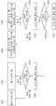
31 to 32 are exemplary diagrams illustrating operations of a terminal corresponding to a telephone receiving screen according to an embodiment of the present invention.
33 to 34 are diagrams illustrating an operation of a terminal corresponding to a clock screen according to an embodiment of the present invention.
35 to 37 are views illustrating exemplary operations of a terminal corresponding to a weather screen according to an embodiment of the present invention.
38 to 39 are exemplary diagrams for changing a font size of a terminal according to an embodiment of the present invention.
이하, 첨부된 도면을 참조하여 본 명세서에 개시된 실시 예를 상세히 설명하되, 도면 부호에 관계없이 동일하거나 유사한 구성요소는 동일한 참조 번호를 부여하고 이에 대한 중복되는 설명은 생략하기로 한다. 이하의 설명에서 사용되는 구성요소에 대한 접미사 "모듈" 및 "부"는 명세서 작성의 용이함만이 고려되어 부여되거나 혼용되는 것으로서, 그 자체로 서로 구별되는 의미 또는 역할을 갖는 것은 아니다. 또한, 본 명세서에 개시된 실시 예를 설명함에 있어서 관련된 공지 기술에 대한 구체적인 설명이 본 명세서에 개시된 실시 예의 요지를 흐릴 수 있다고 판단되는 경우 그 상세한 설명을 생략한다. 또한, 첨부된 도면은 본 명세서에 개시된 실시 예를 쉽게 이해할 수 있도록 하기 위한 것일 뿐, 첨부된 도면에 의해 본 명세서에 개시된 기술적 사상이 제한되지 않으며, 본 발명의 사상 및 기술 범위에 포함되는 모든 변경, 균등물 내지 대체물을 포함하는 것으로 이해되어야 한다.Hereinafter, embodiments of the present invention will be described in detail with reference to the accompanying drawings, wherein like reference numerals are used to designate identical or similar elements, and redundant description thereof will be omitted. The suffix "module" and " part "for the components used in the following description are given or mixed in consideration of ease of specification, and do not have their own meaning or role. In the following description of the embodiments of the present invention, a detailed description of related arts will be omitted when it is determined that the gist of the embodiments disclosed herein may be blurred. It is to be understood that both the foregoing general description and the following detailed description are exemplary and explanatory and are intended to provide further explanation of the invention as claimed. , ≪ / RTI > equivalents, and alternatives.
제1, 제2 등과 같이 서수를 포함하는 용어는 다양한 구성요소들을 설명하는데 사용될 수 있지만, 상기 구성요소들은 상기 용어들에 의해 한정되지는 않는다. 상기 용어들은 하나의 구성요소를 다른 구성요소로부터 구별하는 목적으로만 사용된다.Terms including ordinals, such as first, second, etc., may be used to describe various elements, but the elements are not limited to these terms. The terms are used only for the purpose of distinguishing one component from another.
어떤 구성요소가 다른 구성요소에 "연결되어" 있다거나 "접속되어" 있다고 언급된 때에는, 그 다른 구성요소에 직접적으로 연결되어 있거나 또는 접속되어 있을 수도 있지만, 중간에 다른 구성요소가 존재할 수도 있다고 이해되어야 할 것이다. 반면에, 어떤 구성요소가 다른 구성요소에 "직접 연결되어" 있다거나 "직접 접속되어" 있다고 언급된 때에는, 중간에 다른 구성요소가 존재하지 않는 것으로 이해되어야 할 것이다.It is to be understood that when an element is referred to as being "connected" or "connected" to another element, it may be directly connected or connected to the other element, . On the other hand, when an element is referred to as being "directly connected" or "directly connected" to another element, it should be understood that there are no other elements in between.
단수의 표현은 문맥상 명백하게 다르게 뜻하지 않는 한, 복수의 표현을 포함한다.The singular expressions include plural expressions unless the context clearly dictates otherwise.
본 출원에서, "포함한다" 또는 "가지다" 등의 용어는 명세서상에 기재된 특징, 숫자, 단계, 동작, 구성요소, 부품 또는 이들을 조합한 것이 존재함을 지정하려는 것이지, 하나 또는 그 이상의 다른 특징들이나 숫자, 단계, 동작, 구성요소, 부품 또는 이들을 조합한 것들의 존재 또는 부가 가능성을 미리 배제하지 않는 것으로 이해되어야 한다.In the present application, the terms "comprises", "having", and the like are used to specify that a feature, a number, a step, an operation, an element, a component, But do not preclude the presence or addition of one or more other features, integers, steps, operations, elements, components, or combinations thereof.
본 명세서에서 설명되는 단말기에는 휴대폰, 스마트 폰(smart phone), 노트북 컴퓨터(laptop computer), 디지털방송용 단말기, PDA(personal digital assistants), PMP(portable multimedia player), 네비게이션, 슬레이트 PC(slate PC), 태블릿 PC(tablet PC), 울트라북(ultrabook), 웨어러블 디바이스(wearable device, 예를 들어, 워치형 단말기 (smartwatch), 글래스형 단말기 (smart glass), HMD(head mounted display)) 등이 포함될 수 있다.The terminal described in this specification may be a mobile phone, a smart phone, a laptop computer, a digital broadcasting terminal, a personal digital assistant (PDA), a portable multimedia player (PMP), a navigation device, a slate PC, A tablet PC, an ultrabook, a wearable device (e.g., a smartwatch, a smart glass, a head mounted display (HMD), etc.) .
그러나, 본 명세서에 기재된 실시 예에 따른 구성은 단말기에만 적용 가능한 경우를 제외하면, 디지털 TV, 데스크탑 컴퓨터, 디지털 사이니지 등과 같은 고정 단말기에도 적용될 수도 있음을 본 기술분야의 당업자라면 쉽게 알 수 있을 것이다.However, it will be readily apparent to those skilled in the art that the configuration according to the embodiments described herein may be applied to fixed terminals such as a digital TV, a desktop computer, a digital signage, and the like, .
다음은 도 1을 참고하여 본 발명의 일 실시예에 따른 단말기의 구조를 설명한다.Hereinafter, a structure of a terminal according to an embodiment of the present invention will be described with reference to FIG.
도 1은 본 발명의 일 실시 예와 관련된 단말기의 블록 구성도(block diagram)이다.1 is a block diagram of a terminal according to an embodiment of the present invention.
상기 단말기(100)는 무선 통신부(110), A/V(Audio/Video) 입력부(120), 사용자 입력부(130), 센싱부(140), 출력부(150), 메모리(160), 인터페이스부(170), 제어부(180) 및 전원 공급부(190) 등을 포함할 수 있다. 도 1에 도시된 구성요소들이 필수적인 것은 아니어서, 그보다 많은 구성요소들을 갖거나 그보다 적은 구성요소들을 갖는 단말기가 구현될 수도 있다.The terminal 100 includes a
이하, 상기 구성요소들에 대해 차례로 살펴본다.Hereinafter, the components will be described in order.
무선 통신부(110)는, 단말기(100)와 무선 통신 시스템 사이, 단말기(100)와 다른 단말기(100) 사이, 단말기(100)와 다른 디바이스 사이 또는 단말기(100)와 외부서버 사이의 무선 통신을 가능하게 하는 하나 이상의 모듈을 포함할 수 있다. 또한, 상기 무선 통신부(110)는, 단말기(100)를 하나 이상의 네트워크에 연결하는 하나 이상의 모듈을 포함할 수 있다.The
이러한 무선 통신부(110)는, 방송 수신 모듈(111), 이동통신 모듈(112), 무선 인터넷 모듈(113), 근거리 통신 모듈(114), 위치정보 모듈(115) 중 적어도 하나를 포함할 수 있다.The
방송 수신 모듈(111)은 방송 채널을 통하여 외부의 방송 관리 서버로부터 방송 신호 및/또는 방송 관련된 정보를 수신한다.The
상기 방송 채널은 위성 채널, 지상파 채널을 포함할 수 있다. 상기 방송 관리 서버는, 방송 신호 및/또는 방송 관련 정보를 생성하여 송신하는 서버 또는 기 생성된 방송 신호 및/또는 방송 관련 정보를 제공받아 단말기에 송신하는 서버를 의미할 수 있다. 상기 방송 신호는, TV 방송 신호, 라디오 방송 신호, 데이터 방송 신호를 포함할 뿐만 아니라, TV 방송 신호 또는 라디오 방송 신호에 데이터 방송 신호가 결합한 형태의 방송 신호도 포함할 수 있다.The broadcast channel may include a satellite channel and a terrestrial channel. The broadcast management server may refer to a server for generating and transmitting broadcast signals and / or broadcast related information, or a server for receiving broadcast signals and / or broadcast related information generated by the broadcast management server and transmitting the generated broadcast signals and / or broadcast related information. The broadcast signal may include a TV broadcast signal, a radio broadcast signal, a data broadcast signal, and a broadcast signal in which a data broadcast signal is combined with a TV broadcast signal or a radio broadcast signal.
상기 방송 관련 정보는, 방송 채널, 방송 프로그램 또는 방송 서비스 제공자에 관련한 정보를 의미할 수 있다. 상기 방송 관련 정보는, 이동통신망을 통하여도 제공될 수 있다. 이러한 경우에는 상기 이동통신 모듈(112)에 의해 수신될 수 있다.The broadcast-related information may refer to a broadcast channel, a broadcast program, or information related to a broadcast service provider. The broadcast-related information may also be provided through a mobile communication network. In this case, it may be received by the mobile communication module 112.
상기 방송 관련 정보는 다양한 형태로 존재할 수 있다. 예를 들어, DMB(Digital Multimedia Broadcasting)의 EPG(Electronic Program Guide) 또는 DVB-H(Digital Video Broadcast-Handheld)의 ESG(Electronic Service Guide) 등의 형태로 존재할 수 있다.The broadcast-related information may exist in various forms. For example, an EPG (Electronic Program Guide) of DMB (Digital Multimedia Broadcasting) or an ESG (Electronic Service Guide) of Digital Video Broadcast-Handheld (DVB-H).
상기 방송 수신 모듈(111)은, 예를 들어, DMB-T(Digital Multimedia Broadcasting-Terrestrial), DMB-S(Digital Multimedia Broadcasting-Satellite), MediaFLO(Media Forward Link Only), DVB-H(Digital Video Broadcast-Handheld), ISDB-T(Integrated Services Digital Broadcast-Terrestrial) 등의 디지털 방송 시스템을 이용하여 디지털 방송 신호를 수신할 수 있다. 물론, 상기 방송 수신 모듈(111)은, 상술한 디지털 방송 시스템뿐만 아니라 다른 방송 시스템에 적합하도록 구성될 수도 있다.For example, the
방송 수신 모듈(111)을 통해 수신된 방송 신호 및/또는 방송 관련 정보는 메모리(160)에 저장될 수 있다.The broadcast signal and / or broadcast related information received through the
이동통신 모듈(112)은, 이동 통신망 상에서 기지국, 외부의 단말, 서버 중 적어도 하나와 무선 신호를 송수신한다. 상기 무선 신호는, 음성 호 신호, 화상 통화 호 신호 또는 문자/멀티미디어 메시지 송수신에 따른 다양한 형태의 데이터를 포함할 수 있다.The mobile communication module 112 transmits and receives radio signals to at least one of a base station, an external terminal, and a server on a mobile communication network. The wireless signal may include various types of data depending on a voice call signal, a video call signal or a text / multimedia message transmission / reception.
무선 인터넷 모듈(113)은 무선 인터넷 접속을 위한 모듈을 말하는 것으로, 단말기(100)에 내장되거나 외장될 수 있다. 무선 인터넷 기술로는 WLAN(Wireless LAN)(Wi-Fi), Wibro(Wireless broadband), Wimax(World Interoperability for Microwave Access), HSDPA(High Speed Downlink Packet Access) 등이 이용될 수 있다.The
근거리 통신 모듈(114)은 근거리 통신을 위한 모듈을 말한다. 근거리 통신(short range communication) 기술로 블루투스(Bluetooth), RFID(Radio Frequency Identification), 적외선 통신(IrDA, infrared Data Association), UWB(Ultra Wideband), ZigBee, NFC(Near Field Communication) 등이 이용될 수 있다.The short-
위치정보 모듈(115)은 단말기의 위치(또는 현재 위치)를 획득하기 위한 모듈로서, 그의 대표적인 예로는 GPS(Global Positioning System) 모듈 또는 WiFi(Wireless Fidelity) 모듈이 있다. 예를 들어, 단말기는 GPS모듈을 활용하면, GPS 위성에서 보내는 신호를 이용하여 단말기의 위치를 획득할 수 있다. 다른 예로서, 단말기는 Wi-Fi모듈을 활용하면, Wi-Fi모듈과 무선신호를 송신 또는 수신하는 무선 AP(Wireless Access Point)의 정보에 기반하여, 단말기의 위치를 획득할 수 있다. 필요에 따라서, 위치정보모듈(115)은 치환 또는 부가적으로 단말기의 위치에 관한 데이터를 얻기 위해 무선 통신부(110)의 다른 모듈 중 어느 기능을 수행할 수 있다. 위치정보모듈(115)은 단말기의 위치(또는 현재 위치)를 획득하기 위해 이용되는 모듈로, 단말기의 위치를 직접적으로 계산하거나 획득하는 모듈로 한정되지는 않는다.The
도 1을 참조하면, A/V(Audio/Video) 입력부(120)는 오디오 신호 또는 비디오 신호 입력을 위한 것으로, 이에는 카메라(121)와 마이크(122) 등이 포함될 수 있다. 카메라(121)는 화상 통화모드 또는 촬영 모드에서 이미지 센서에 의해 얻어지는 정지영상 또는 동영상 등의 화상 프레임을 처리한다. 처리된 화상 프레임은 디스플레이부(151)에 표시될 수 있다.Referring to FIG. 1, an A / V (Audio / Video)
카메라(121)에서 처리된 화상 프레임은 메모리(160)에 저장되거나 무선 통신부(110)를 통하여 외부로 전송될 수 있다. 카메라(121)는 사용 환경에 따라 2개 이상이 구비될 수도 있다.The image frame processed by the
마이크(122)는 통화모드 또는 녹음모드, 음성인식 모드 등에서 마이크로폰(Microphone)에 의해 외부의 음향 신호를 입력받아 전기적인 음성 데이터로 처리한다. 처리된 음성 데이터는 통화모드인 경우 이동통신 모듈(112)을 통하여 이동통신 기지국으로 송신 가능한 형태로 변환되어 출력될 수 있다. 마이크(122)에는 외부의 음향 신호를 입력받는 과정에서 발생되는 잡음(noise)을 제거하기 위한 다양한 잡음 제거 알고리즘이 구현될 수 있다.The
입력부(120)는, 영상 신호 입력을 위한 카메라(121) 또는 영상 입력부, 오디오 신호 입력을 위한 마이크로폰(microphone, 122), 또는 오디오 입력부, 사용자로부터 정보를 입력받기 위한 사용자 입력부(123, 예를 들어, 터치키(touch key), 푸시키(mechanical key) 등)를 포함할 수 있다. 입력부(120)에서 수집한 음성 데이터나 이미지 데이터는 분석되어 사용자의 제어명령으로 처리될 수 있다.The
사용자 입력부(130)는 상술한 사용자 입력부(123)와 동일한 구성일 수 있다.The
센싱부(140)는 단말기 내 정보, 단말기를 둘러싼 주변 환경 정보 및 사용자 정보 중 적어도 하나를 센싱하기 위한 하나 이상의 센서를 포함할 수 있다. 예를 들어, 센싱부(140)는 근접센서(141, proximity sensor), 조도 센서(142, illumination sensor), 터치 센서(touch sensor), 가속도 센서(acceleration sensor), 자기 센서(magnetic sensor), 중력 센서(G-sensor), 자이로스코프 센서(gyroscope sensor), 모션 센서(motion sensor), RGB 센서, 적외선 센서(IR 센서: infrared sensor), 지문인식 센서(finger scan sensor), 초음파 센서(ultrasonic sensor), 광 센서(optical sensor, 예를 들어, 카메라(121 참조)), 마이크로폰(microphone, 122 참조), 배터리 게이지(battery gauge), 환경 센서(예를 들어, 기압계, 습도계, 온도계, 방사능 감지 센서, 열 감지 센서, 가스 감지 센서 등), 화학 센서(예를 들어, 전자 코, 헬스케어 센서, 생체 인식 센서 등) 중 적어도 하나를 포함할 수 있다. 한편, 본 명세서에 개시된 단말기는, 이러한 센서들 중 적어도 둘 이상의 센서에서 센싱되는 정보들을 조합하여 활용할 수 있다.The
또한, 센싱부(140)는 단말기(100)에 결합된 단말기 케이스(200)의 상태를 센싱할 수 있다. 예를 들면 센싱부(140)에 포함된 자기 센서(145)를 통해 단말기 케이스(200)의 상태를 센싱할 수 있다. 다른 예를 들면 센싱부(140)에 포함된 전면 센서(146) 또는 후면 센서(147)를 통해 단말기 케이스(200)의 상태를 센싱할 수 있다. 여기서 단말기 케이스(200)의 상태는 단말기(100)와 결합된 단말기 케이스(200)의 케이스 전면부(210)의 위치를 의미할 수 있다. 센싱부(140)의 단말기 케이스(200)의 상태 센싱에 대해서는 후술하기로 한다.The
출력부(150)는 시각, 청각 또는 촉각 등과 관련된 출력을 발생시키기 위한 것으로, 디스플레이부(151), 음향 출력 모듈(152), 알람부(153), 햅틱모듈(154) 중 적어도 하나를 포함할 수 있다. 디스플레이부(151)는 터치 센서와 상호 레이어 구조를 이루거나 일체형으로 형성됨으로써, 터치 스크린을 구현할 수 있다. 이러한 터치 스크린은, 단말기(100)와 사용자 사이의 입력 인터페이스를 제공하는 사용자 입력부(123)로써 기능함과 동시에, 단말기(100)와 사용자 사이의 출력 인터페이스를 제공할 수 있다.The
디스플레이부(151)는 단말기(100)에서 처리되는 정보를 표시(출력)한다. 예를 들어, 단말기가 통화모드인 경우 통화와 관련된 UI(User Interface) 또는 GUI(Graphic User Interface)를 표시한다. 단말기(100)가 화상통화 모드 또는 촬영 모드인 경우에는 촬영 또는/및 수신된 영상 또는 UI, GUI를 표시한다.The
디스플레이부(151)는 액정 디스플레이(liquid crystal display, LCD), 박막 트랜지스터 액정 디스플레이(thin film transistor-liquid crystal display, TFT LCD), 유기 발광 다이오드(organic light-emitting diode, OLED), 플렉시블 디스플레이(flexible display), 3차원 디스플레이(3D display) 중에서 적어도 하나를 포함할 수 있다.The
이들 중 일부 디스플레이는 그를 통해 외부를 볼 수 있도록 투명형 또는 광투과형으로 구성될 수 있다. 이는 투명 디스플레이라 호칭될 수 있는데, 상기 투명 디스플레이의 대표적인 예로는 TOLED(Transparant OLED) 등이 있다. 디스플레이부(151)의 후방 구조 또한 광 투과형 구조로 구성될 수 있다. 이러한 구조에 의하여, 사용자는 단말기 바디의 디스플레이부(151)가 차지하는 영역을 통해 단말기 바디의 후방에 위치한 사물을 볼 수 있다.Some of these displays may be transparent or light transmissive so that they can be seen through. This can be referred to as a transparent display, and a typical example of the transparent display is TOLED (Transparent OLED) and the like. The rear structure of the
단말기(100)의 구현 형태에 따라 디스플레이부(151)가 2개 이상 존재할 수 있다. 예를 들어, 단말기(100)에는 복수의 디스플레이부들이 하나의 면에 이격되거나 일체로 배치될 수 있고, 또한 서로 다른 면에 각각 배치될 수도 있다.There may be two or
디스플레이부(151)와 터치 동작을 감지하는 센서(이하, '터치 센서'라 함)(144)가 상호 레이어 구조를 이루는 경우(이하, '터치 스크린'이라 함)에, 디스플레이부(151)는 출력 장치 이외에 입력 장치로도 사용될 수 있다. 터치 센서(144)는, 예를 들어, 터치 필름, 터치 시트, 터치 패드 등의 형태를 가질 수 있다.(Hereinafter, referred to as a 'touch screen') in which a
터치 센서(144)는 디스플레이부(151)의 특정 부위에 가해진 압력 또는 디스플레이부(151)의 특정 부위에 발생하는 정전 용량 등의 변화를 전기적인 입력신호로 변환하도록 구성될 수 있다. 터치 센서(144)는 터치 되는 위치 및 면적뿐만 아니라, 터치 시의 압력 및 정전용량까지도 검출할 수 있도록 구성될 수 있다.The touch sensor 144 may be configured to convert a change in a pressure applied to a specific portion of the
터치 센서(144)에 대한 터치 입력이 있는 경우, 그에 대응하는 신호(들)는 터치 제어기로 보내진다. 터치 제어기는 그 신호(들)를 처리한 다음 대응하는 데이터를 제어부(180)로 전송한다. 이로써, 제어부(180)는 디스플레이부(151)의 어느 영역이 터치 되었는지 여부 등을 알 수 있게 된다.If there is a touch input to the touch sensor 144, the corresponding signal (s) is sent to the touch controller. The touch controller processes the signal (s) and transmits the corresponding data to the
또한, 제어부(180)는 터치 시의 면적, 압력 및 정전용량을 기초로 사용자의 터치 입력의 종류를 판단할 수 있다. 이에 따라, 제어부(180)는 사용자의 손가락 터치, 손톱 터치, 손가락 마디 터치, 복수의 손가락을 이용한 멀티 터치를 구분할 수 있다.In addition, the
도 1을 참조하면, 상기 터치스크린에 의해 감싸지는 단말기의 내부 영역 또는 상기 터치 스크린의 근처에 근접 센서(141)가 배치될 수 있다. 상기 근접 센서(141)는 소정의 검출면에 접근하는 물체, 혹은 근방에 존재하는 물체의 유무를 전자계의 힘 또는 적외선을 이용하여 기계적 접촉이 없이 검출하는 센서를 말한다. 근접 센서(141)는 접촉식 센서보다는 그 수명이 길며 그 활용도 또한 높다.Referring to FIG. 1, a proximity sensor 141 may be disposed in an inner region of a terminal or a proximity of the touch screen, which is surrounded by the touch screen. The proximity sensor 141 refers to a sensor that detects the presence of an object approaching a predetermined detection surface or an object existing in the vicinity of the detection surface without mechanical contact using an electromagnetic force or an infrared ray. The proximity sensor 141 has a longer life span than the contact-type sensor, and its utilization is also high.
상기 근접 센서(141)의 예로는 투과형 광전 센서, 직접 반사형 광전 센서, 미러 반사형 광전 센서, 고주파 발진형 근접 센서, 정전용량형 근접 센서, 자기형 근접 센서, 적외선 근접 센서 등이 있다. 상기 터치스크린이 정전식인 경우에는 상기 포인터의 근접에 따른 전계의 변화로 상기 포인터의 근접을 검출하도록 구성된다. 이 경우 상기 터치 스크린(터치 센서)(144)은 근접 센서로 분류될 수도 있다.Examples of the proximity sensor 141 include a transmission type photoelectric sensor, a direct reflection type photoelectric sensor, a mirror reflection type photoelectric sensor, a high frequency oscillation type proximity sensor, a capacitive proximity sensor, a magnetic proximity sensor, and an infrared proximity sensor. And to detect the proximity of the pointer by the change of the electric field along the proximity of the pointer when the touch screen is electrostatic. In this case, the touch screen (touch sensor) 144 may be classified as a proximity sensor.
한편 근접 센서(141)는 단말기(100)의 전면 방향을 센싱하는 전면 센서(146)와 단말기(100)의 후면 방향을 센싱하는 후면 센서(147)를 포함할 수 있다.The proximity sensor 141 may include a
이하에서는 설명의 편의를 위해, 상기 터치스크린 상에 포인터가 접촉되지 않으면서 근접되어 상기 포인터가 상기 터치스크린 상에 위치함이 인식되도록 하는 행위를 "근접 터치(proximity touch)"라고 칭하고, 상기 터치스크린 상에 포인터가 실제로 접촉되는 행위를 "접촉 터치(contact touch)"라고 칭한다. 상기 터치스크린 상에서 포인터로 근접 터치가 되는 위치라 함은, 상기 포인터가 근접 터치될 때 상기 포인터가 상기 터치스크린에 대해 수직으로 대응되는 위치를 의미한다.Hereinafter, for convenience of explanation, the act of recognizing that the pointer is positioned on the touch screen while the pointer is not in contact with the touch screen is referred to as "proximity touch" The act of actually touching the pointer on the screen is called "contact touch. &Quot; The position where the pointer is proximately touched on the touch screen means a position where the pointer is vertically corresponding to the touch screen when the pointer is touched.
상기 근접센서는, 근접 터치와, 근접 터치 패턴(예를 들어, 근접 터치 거리, 근접 터치 방향, 근접 터치 속도, 근접 터치 시간, 근접 터치 위치, 근접 터치 이동 상태 등)을 감지한다. 상기 감지된 근접 터치 동작 및 근접 터치 패턴에 상응하는 정보는 터치 스크린상에 출력될 수 있다.The proximity sensor detects a proximity touch and a proximity touch pattern (e.g., a proximity touch distance, a proximity touch direction, a proximity touch speed, a proximity touch time, a proximity touch position, a proximity touch movement state, and the like). Information corresponding to the detected proximity touch operation and the proximity touch pattern may be output on the touch screen.
음향 출력 모듈(152)은 호신호 수신, 통화모드 또는 녹음 모드, 음성인식 모드, 방송수신 모드 등에서 무선 통신부(110)로부터 수신되거나 메모리(160)에 저장된 오디오 데이터를 출력할 수 있다. 음향 출력 모듈(152)은 단말기(100)에서 수행되는 기능(예를 들어, 호신호 수신음, 메시지 수신음 등)과 관련된 음향 신호를 출력하기도 한다. 이러한 음향 출력 모듈(152)에는 리시버(Receiver), 스피커(speaker), 버저(Buzzer) 등이 포함될 수 있다.The
알람부(153)는 단말기(100)의 이벤트 발생을 알리기 위한 신호를 출력한다. 단말기에서 발생 되는 이벤트의 예로는 호 신호 수신, 메시지 수신, 키 신호 입력, 터치 입력 등이 있다. 알람부(153)는 비디오 신호나 오디오 신호 이외에 다른 형태, 예를 들어 진동으로 이벤트 발생을 알리기 위한 신호를 출력할 수도 있다. 상기 비디오 신호나 오디오 신호는 디스플레이부(151)나 음성 출력 모듈(152)을 통해서도 출력될 수 있어서, 그들(151,152)은 알람부(153)의 일부로 분류될 수도 있다.The
햅틱 모듈(haptic module)(154)은 사용자가 느낄 수 있는 다양한 촉각 효과를 발생시킨다. 햅틱 모듈(154)이 발생시키는 촉각 효과의 대표적인 예로는 진동이 있다. 햅택 모듈(154)이 발생하는 진동의 세기와 패턴 등은 제어가능하다. 예를 들어, 서로 다른 진동을 합성하여 출력하거나 순차적으로 출력할 수도 있다.The
햅틱 모듈(154)은, 진동 외에도, 접촉 피부면에 대해 수직 운동하는 핀 배열, 분사구나 흡입구를 통한 공기의 분사력이나 흡입력, 피부 표면에 대한 스침, 전극(eletrode)의 접촉, 정전기력 등의 자극에 의한 효과와, 흡열이나 발열 가능한 소자를 이용한 냉온감 재현에 의한 효과 등 다양한 촉각 효과를 발생시킬 수 있다.In addition to the vibration, the
햅틱 모듈(154)은 직접적인 접촉을 통해 촉각 효과의 전달할 수 있을 뿐만 아니라, 사용자가 손가락이나 팔 등의 근 감각을 통해 촉각 효과를 느낄 수 있도록 구현할 수도 있다. 햅틱 모듈(154)은 단말기(100)의 구성 태양에 따라 2개 이상이 구비될 수 있다.The
또한, 햅틱 모듈(154)은 진동을 발생시킬 수 있는 진동 소자를 포함할 수 있다. 예를 들면, 햅틱 모듈(154)에는 하나 이상의 진동 모터가 포함될 수 있으며, 진동 모터는 바 타임, 코인 타입 등 다양한 형태일 수 있다.In addition, the
그리고 햅틱 모듈(154)은 단말기(100)의 형태에 따라 다양한 위치에 구비될 수 있다. 예를 들면, 와치 타입의 단말기(300)인 경우, 와치 타입의 단말기(300)의 본체(301), 밴드(302) 중 하나 이상에 햅틱 모듈(154)이 포함될 수 있다.The
또한, 메모리(160)는 단말기(100)의 다양한 기능을 지원하는 데이터를 저장한다. 메모리(160)는 단말기(100)에서 구동되는 다수의 응용 프로그램(application program 또는 애플리케이션(application)), 단말기(100)의 동작을 위한 데이터들, 명령어들을 저장할 수 있다. 이러한 응용 프로그램 중 적어도 일부는, 무선 통신을 통해 외부 서버로부터 다운로드 될 수 있다. 또한 이러한 응용 프로그램 중 적어도 일부는, 단말기(100)의 기본적인 기능(예를 들어, 전화 착신, 발신 기능, 메시지 수신, 발신 기능)을 위하여 출고 당시부터 단말기(100)상에 존재할 수 있다. 한편, 응용 프로그램은, 메모리(160)에 저장되고, 단말기(100) 상에 설치되어, 제어부(180)에 의하여 상기 단말기의 동작(또는 기능)을 수행하도록 구동될 수 있다.In addition, the
메모리(160)는 플래시 메모리 타입(flash memory type), 하드디스크 타입(hard disk type), 멀티미디어 카드 마이크로 타입(multimedia card micro type), 카드 타입의 메모리(예를 들어 SD 또는 XD 메모리 등), 램(Random Access Memory, RAM), SRAM(Static Random Access Memory), 롬(Read-Only Memory, ROM), EEPROM(Electrically Erasable Programmable Read-Only Memory), PROM(Programmable Read-Only Memory), 자기 메모리, 자기 디스크, 광디스크 중 적어도 하나의 타입의 저장매체를 포함할 수 있다. 단말기(100)는 인터넷(internet)상에서 상기 메모리(160)의 저장 기능을 수행하는 웹 스토리지(web storage)와 관련되어 동작할 수도 있다.The
인터페이스부(170)는 단말기(100)에 연결되는 모든 홈 디바이스와의 통로 역할을 한다. 인터페이스부(170)는 외부 기기로부터 데이터를 전송받거나, 전원을 공급받아 단말기(100) 내부의 각 구성 요소에 전달하거나, 단말기(100) 내부의 데이터가 외부 기기로 전송되도록 한다. 예를 들어, 유/무선 헤드셋 포트, 외부 충전기 포트, 유/무선 데이터 포트, 메모리 카드(memory card) 포트, 식별 모듈이 구비된 장치를 연결하는 포트, 오디오 I/O(Input/Output) 포트, 비디오 I/O(Input/Output) 포트, 이어폰 포트 등이 인터페이스부(170)에 포함될 수 있다.The
식별 모듈은 단말기(100)의 사용 권한을 인증하기 위한 각종 정보를 저장한 칩으로서, 사용자 인증 모듈(User Identify Module, UIM), 가입자 인증 모듈(Subscriber Identity Module, SIM), 범용 사용자 인증 모듈(Universal Subscriber Identity Module, USIM) 등을 포함할 수 있다. 식별 모듈이 구비된 장치(이하 '식별 장치')는, 스마트 카드(smart card) 형식으로 제작될 수 있다. 따라서 식별 장치는 포트를 통하여 단말기(100)와 연결될 수 있다.The identification module is a chip for storing various information for authenticating the usage right of the terminal 100 and includes a user identification module (UIM), a subscriber identity module (SIM), a universal user authentication module A Subscriber Identity Module (USIM), and the like. Devices with identification modules (hereinafter referred to as "identification devices") can be manufactured in a smart card format. Accordingly, the identification device can be connected to the terminal 100 through the port.
상기 인터페이스부(170)는 단말기(100)가 외부 크래들(cradle)과 연결될 때 상기 크래들로부터의 전원이 상기 단말기(100)에 공급되는 통로가 되거나, 사용자에 의해 상기 크래들에서 입력되는 각종 명령 신호가 상기 단말기로 전달되는 통로가 될 수 있다. 상기 크래들로부터 입력되는 각종 명령 신호 또는 상기 전원은 상기 단말기가 상기 크래들에 정확히 장착되었음을 인지하기 위한 신호로 동작될 수도 있다.When the terminal 100 is connected to an external cradle, the
제어부(controller, 180)는 통상적으로 단말기의 전반적인 동작을 제어한다. 예를 들어 음성 통화, 데이터 통신, 화상 통화 등을 위한 관련된 제어 및 처리를 수행한다. 제어부(180)는 멀티 미디어 재생을 위한 멀티미디어 모듈(181)을 구비할 수도 있다. 멀티미디어 모듈(181)은 제어부(180) 내에 구현될 수도 있고, 제어부(180)와 별도로 구현될 수도 있다.The
상기 제어부(180)는 상기 터치스크린 상에서 행해지는 필기 입력 또는 그림 그리기 입력을 각각 문자 및 이미지로 인식할 수 있는 패턴 인식 처리를 행할 수 있다.The
또한, 제어부(180)는 센싱부(140)로부터 단말기 케이스(200)에 대한 센싱값을 전달받아, 단말기 케이스(200)의 상태를 인식할 수 있다.The
전원 공급부(190)는 제어부(180)의 제어에 의해 외부의 전원, 내부의 전원을 인가받아 각 구성요소들의 동작에 필요한 전원을 공급한다.The
여기에 설명되는 다양한 실시예는 예를 들어, 소프트웨어, 하드웨어 또는 이들의 조합된 것을 이용하여 컴퓨터 또는 이와 유사한 장치로 읽을 수 있는 기록매체 내에서 구현될 수 있다.The various embodiments described herein may be embodied in a recording medium readable by a computer or similar device using, for example, software, hardware, or a combination thereof.
하드웨어적인 구현에 의하면, 여기에 설명되는 실시예는 ASICs (application specific integrated circuits), DSPs (digital signal processors), DSPDs (digital signal processing devices), PLDs (programmable logic devices), FPGAs (field programmable gate arrays, 프로세서(processors), 제어기(controllers), 마이크로 컨트롤러(micro-controllers), 마이크로 프로세서(microprocessors), 기타 기능 수행을 위한 전기적인 유닛 중 적어도 하나를 이용하여 구현될 수 있다. 일부의 경우에 그러한 실시예들이 제어부(180)에 의해 구현될 수 있다.According to a hardware implementation, the embodiments described herein may be implemented as application specific integrated circuits (ASICs), digital signal processors (DSPs), digital signal processing devices (DSPDs), programmable logic devices (PLDs), field programmable gate arrays May be implemented using at least one of processors, controllers, micro-controllers, microprocessors, and other electronic units for performing other functions. In some cases, May be implemented by the
소프트웨어적인 구현에 의하면, 절차나 기능과 같은 실시예들은 적어도 하나의 기능 또는 작동을 수행하게 하는 별개의 소프트웨어 모듈과 함께 구현될 수 있다. 소프트웨어 코드는 적절한 프로그램 언어로 쓰여진 소프트웨어 어플리케이션에 의해 구현될 수 있다. 소프트웨어 코드는 메모리(160)에 저장되고, 제어부(180)에 의해 실행될 수 있다.According to a software implementation, embodiments such as procedures or functions may be implemented with separate software modules that perform at least one function or operation. The software code may be implemented by a software application written in a suitable programming language. The software codes are stored in the
상술한 단말기(100)는 휴대형 단말기일 수도 있고, 거치형 단말기일 수도 있다. 따라서 단말기(100)는 사용자가 직접 휴대하는 형태일 수 있으며, 일정 영역에 거치된 형태일 수도 있다.The terminal 100 may be a portable terminal or a stationary terminal. Accordingly, the terminal 100 may be carried by the user directly, or may be mounted in a predetermined area.
한편, 단말기는 사용자가 주로 손에 쥐고 사용하는 차원을 넘어서, 신체에 착용할 수 있는 웨어러블 디바이스(wearable device)로 확장될 수 있다. 이러한 웨어러블 디바이스에는 스마트 워치(smart watch), 스마트 글래스(smart glass), HMD(head mounted display) 등이 있다.On the other hand, the terminal can be extended to a wearable device which can be worn on the body beyond the dimension that the user holds mainly in the hand. These wearable devices include smart watch, smart glass, and head mounted display (HMD).
상술한 단말기(100)에 결합 가능한 단말기 케이스(200)에 대해 이하 상세히설명한다.The
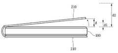
도 2는 본 발명의 일 실시 예에 따른 단말기 케이스를 나타내는 예시도이다.2 is an exemplary view illustrating a terminal case according to an embodiment of the present invention.
도 2를 참조하면, 단말기 케이스(200)는 케이스 전면부(210), 케이스 후면부(220)을 포함할 수 있다. 또한 단말기 케이스(200)는 케이스 전면부(210)와 케이스 후면부(220)를 연결하는 연결부(미도시)를 포함할 수 있고, 단말기 케이스(200)와 단말기(100)의 체결을 위한 체결부(미도시)를 포함할 수 있다.Referring to FIG. 2, the
이들 각각의 구성을 좀 더 상세히 설명하면, 체결부(미도시)는 단말기(100)의 측면과 후면을 커버 가능하도록 형성되며, 단말기(100)의 착탈이 가능하도록 전방은 개구된 형상을 갖는다. 따라서 체결부(미도시)의 내부에는 단말기(100)가 수용 가능한 공간이 형성된다.The fastening portion (not shown) is formed to cover the side and rear surfaces of the terminal 100, and has a front opening shape so that the terminal 100 can be attached and detached. Therefore, a space accommodating the terminal 100 is formed inside the fastening portion (not shown).
단말기 케이스(200)에는 단말기(100)의 일면에 구비되는 카메라 또는 기타 조작 버튼이 노출되도록 하기 위한 개구부가 형성될 수 있다. 예를 들면 단말기 케이스(200)에는 단말기의 전면, 측면, 후면 중 하나 이상에 구비되는 카메라 또는 기타 조작 버튼이 노출되도록 하기 위한 하나 이상의 개구부가 형성될 수 있다.An opening for exposing a camera or other operation buttons provided on one surface of the terminal 100 may be formed in the
케이스 전면부(210)는 단말기(100)의 전면에 대응되는 형상을 갖는 판상의 부재로 이루어진다. 케이스 전면부(210)는 개구부가 구비될 수 있다. 케이스 전면부(210)의 개구부는 케이스 전면부(210)의 일부가 절개되어 형성된다. 절개되어 형성된 개구부는 빈 공간으로 남아 있을 수 있으며 실시예에 따라서는 개구부에는 투명 필름이 부착될 수 있다. 투명 필름은 터치가 가능한 필름이 사용될 수 있다. 또한 투명 필름은 개구부를 통해 보이는 디스플레이부의 전원이 턴 오프 되어있는 경우 거울 역할을 하는 특수 필름이 사용될 수 있다. 예를 들면, 사용자는 전면 개구부(270)를 통해 단말기(100)의 디스플레이부(151)에 표시되는 화상 또는 영상을 볼 수도 있으며, 디스플레이부(151)에 터치 입력할 수도 있다.The case
또한, 케이스 전면부(210)에는 단말기(100)의 센서에 대응하는 개구부가 더 포함될 수 있다. 이에 대해서는 후술한다.In addition, an opening corresponding to the sensor of the terminal 100 may be further included in the case
케이스 후면부(220)는 단말기(100)의 후면에 대응되는 형상을 갖는 판상의 부재로 이루어진다. 케이스 후면부(220)는 개구부가 구비될 수 있다. 케이스 후면부(220)의 개구부는 케이스 후면부(220)의 일부가 절개되어 형성된다. 절개되어 형성된 개구부는 빈 공간으로 남아 있을 수 있으며, 실시예에 따라서는 개구부에는 투명 필름이 부착될 수 있다. 투명 필름은 터치가 가능한 필름이 사용될 수 있다. 예를 들어 케이스 후면부(220)는 단말기(100)의 카메라(121)에 대응하는 제1 후면 개구부(220a)를 포함할 수 있다. 또한, 케이스 후면부(220)는 단말기(100)의 후면에 구비된 조작 버튼에 대응하는 제2 후면 개구부(220b)를 포함할 수 있다.The case
연결부(미도시)는 케이스 전면부(210)와 케이스 후면부(220)를 연결할 수 있고, 유연한(flexible) 소재로 이루어질 수 있다.The connection part (not shown) may connect the case
한편, 케이스 전면부(210)에 자성체가 장착될 수 있다. 이에 대해 도 3을 참조하여 설명한다.On the other hand, a magnetic body may be mounted on the case
도 3은 본 발명의 일 실시 예에 따른 자성체가 장착된 단말기 케이스(200)를 나타내는 예시도이다.3 is an exemplary view illustrating a
도 3을 참조하면, 케이스 전면부(210)는 자성체인 전면 자성체(231)을 포함할 수 있다. 케이스 전면부(210)에 전면 자성체(231)가 포함된 경우, 케이스 전면부(210)가 열리고 닫힘에 따라 자기장의 변화가 일어나게 된다. 단말기 케이스(200)와 결합된 단말기(100)는 이러한 자기장의 변화를 센싱부(140)를 통해 감지할 수 있다. 이에 대해서는 후술한다.Referring to FIG. 3, the case
또한, 케이스 후면부(220)에도 자성체가 장착될 수 있다. 이에 대해 도 4를 참조하여 설명한다.Further, a magnetic substance may be mounted on the case
도 4는 본 발명의 다른 실시 예에 따른 자성체가 장착된 단말기 케이스를 나타내는 예시도이다.4 is an exemplary view showing a terminal case with a magnetic body according to another embodiment of the present invention.
도 4를 참조하면, 케이스 전면부(210) 및 케이스 후면부(220) 각각은 자성체인 전면 자성체(231), 후면 자성체(233)을 각각 포함할 수 있다. 케이스 전면부(210)에 전면 자성체(231)가 포함된 경우, 케이스 전면부(210)가 열리고 닫힘에 따라 자기장의 변화가 일어나게 된다. 케이스 후면부(220)에 후면 자성체(233)가 포함된 경우, 케이스 전면부(210)가 열리고 닫힘에 따라 단말기 케이스(200)와 결합된 단말기(100)는 이러한 자기장의 변화를 센싱부(140)를 통해 감지할 수 있다. 구체적으로 센싱부(140)는 단말기(100)의 전면 또는 후면 방향의 자기장의 변화를 감지할 수 있다. 예를 들면, 센싱부(140)는 케이스 전면부(210)가 단말기(100)의 전면에 위치하는 경우의 전면 자성체(231), 후면 자성체(233) 각각에 대한 자기장을 감지할 수 있다. 또한, 센싱부(140)는 케이스 전면부(210)가 단말기(100)의 후면에 위치하는 경우의 전면 자성체(231), 후면 자성체(233) 각각에 대한 자기장을 감지할 수 있다. 또한, 센싱부(140)는 케이스 전면부(210)가 단말기(100)의 전면 또는 후면에 위치하지 않는 경우의 전면 자성체(231), 후면 자성체(233) 각각에 대한 자기장을 감지할 수도 있다. 이에 대해서는 후술한다.Referring to FIG. 4, the
한편, 전면 자성체(231)는 케이스 전면부(210)가 단말기(100)의 후면에 위치하는 경우, 후면 자성체(233)와 자기적으로 결합될 수도 있다.The front
이하, 도 5 내지 도 6을 참조하여, 상술한 단말기 케이스(200)에 포함된 자성체를 감지하는 센싱부(140)에 대해 구체적으로 설명한다.Hereinafter, the
도 5는 본 발명의 일 실시 예에 따른 단말기의 자기 센서를 나타내는 예시도이다.5 is a diagram illustrating an example of a magnetic sensor of a terminal according to an embodiment of the present invention.
도 5를 참조하면, 단말기(100)는 자기장을 감지하는 자기 센서(145)를 포함할 수 있다. 자기 센서(145)는 센싱부(140)에 포함될 수 있다. 자기 센서(145)는 하나 이상의 자성체에 대응하는 자기장 크기, 자기장 방향을 감지할 수 있다. 예를 들면, 자기 센서(145)는 케이스 전면부(210)의 움직임에 따른, 전면 자성체(231)에 의한 자기장 변화를 감지할 수 있다. 또한, 자기 센서(145)는 케이스 전면부(210)에 포함된 전면 자성체(231) 및 케이스 후면부(220)에 포함된 후면 자성체(233) 각각의 자기장 변화를 감지할 수도 있다. 한편, 자기 센서(145)는 전면 자성체(231), 후면 자성체(233) 각각에 대응하는 위치에 구비될 수 있다.Referring to FIG. 5, the terminal 100 may include a
한편, 자기 센서(145)는 복수의 자기 센서를 포함할 수 있다. 이에 대해 도 6을 참조하여 설명한다.On the other hand, the
도 6은 본 발명의 일 실시 예에 따른 복수의 자기 센서를 포함하는 단말기의 단면을 나타내는 단면도이다.6 is a cross-sectional view illustrating a terminal including a plurality of magnetic sensors according to an embodiment of the present invention.
도 6을 참조하면, 단말기(100)는 복수의 자기 센서인 전면 자기 센서(146) 및 후면 자기 센서(147)을 포함하는 자기 센서(145)를 포함할 수 있다. 전면 자기 센서(146)는 단말기(100)의 전면 방향에 대한 자기장을 감지할 수 있다. 후면 자기 센서(147)은 단말기(100)의 후면 방향에 대한 자기장을 감지할 수 있다. 이에 따라 자기 센서(145)는 단말기(100)의 전면, 후면 중 하나 이상의 방향에 대한 자기장을 각각 감지할 수 있다.Referring to FIG. 6, the terminal 100 may include a
한편, 단말기(100)는 근접 센서(141)를 통해 단말기 케이스(200)의 상태를 인식할 수 있다. 구체적으로 단말기(100)는 단말기(100)의 일면에 구비된 근접 센서를 통해 단말기 케이스(200)를 센싱할 수 있다. 이에 대해 도 7 내지 도 9를 참조하여 설명한다.Meanwhile, the terminal 100 can recognize the state of the
도 7은 본 발명의 일 실시 예에 따른 단말기의 전면 센서를 나타내는 예시도이다.7 is an exemplary view illustrating a front sensor of a terminal according to an embodiment of the present invention.
도 7을 참조하면, 단말기(100)는 단말기의 전면에 전면센서(148)를 구비할 수 있다. 전면센서(148)은 단말기(100)의 전면 방향에 대해 센싱할 수 있다. 이에 따라 전면센서(148)은 단말기 케이스(200)의 케이스 전면부(210)을 센싱할 수 있다. 예를 들면, 전면센서(148)는 케이스 전면부(210)가 단말기(100)의 전면을 덮고 있는 상태, 케이스 전면부(210)가 단말기(100)의 전면을 덮고 있지 않은 상태 각각을 센싱할 수 있다.Referring to FIG. 7, the terminal 100 may include a
도 8을 참조하여, 전면센서(148)의 케이스 전면부(210) 센싱을 설명한다.Referring to Fig. 8, the case
도 8은 본 발명의 일 실시 예에 따른 단말기의 전면센서의 센싱을 나타내는 예시도이다.8 is a diagram illustrating sensing of a front sensor of a terminal according to an exemplary embodiment of the present invention.
도 8을 참조하면, 단말기(100)의 전면센서(148)는 케이스 전면부(210)가 단말기(100)를 덮고 있는 상태일 때, 전면센서(148)에 대응하는 케이스 전면부(210)를 센싱할 수 있다. 또한, 전면센서(148)는 전면센서(148)에 대응하는 케이스 전면부(210)와의 거리를 센싱할 수도 있다.8, the
한편, 단말기(100)는 단말기(100)의 후면에 후면센서(149)를 구비할 수도 있다. 이에 대해 도 9를 참조하여 설명한다.Meanwhile, the terminal 100 may include a
도 9는 본 발명의 일 실시 예에 따른 단말기 케이스와 결합된 단말기를 나타내는 예시도이다.9 is an exemplary view illustrating a terminal combined with a terminal case according to an embodiment of the present invention.
도 9를 참조하면, 단말기 케이스(200)와 결합된 단말기(100)의 후면에 구비된 후면센서(149), 카메라(121), 조작 버튼(124) 각각이 케이스 후면부(220)에 포함된 하나 이상의 개구부를 통해 노출될 수 있다. 예를 들면, 케이스 후면부(220)는 카메라(121)에 대응하는 제1 후면 개구부(220a), 조작 버튼(124)에 대응하는 제2 후면 개구부(220b), 후면센서(149)에 대응하는 제3 후면 개구부(220c)를 구비될 수 있다.9, the
후면센서(149)는 단말기(100)의 후면 방향에 대해 센싱할 수 있다. 이에 따라, 후면센서(149)는 케이스 전면부(210)가 단말기(100)의 후면에 대해 젖혀진 경우, 케이스 전면부(210)를 센싱할 수 있다. 이에 대해 도 10을 참조하여 설명한다.The
도 10은 본 발명의 일 실시 예에 따른 단말기의 후면센서의 센싱을 나타내는 예시도이다.10 is an exemplary diagram illustrating sensing of a rear sensor of a terminal according to an embodiment of the present invention.
도 10을 참조하면, 단말기(100)의 후면센서(149)는 케이스 전면부(210)가 단말기의 후면으로 젖혀진 경우, 케이스 전면부(210)를 센싱할 수 있다. 이에 따라 후면센서(149)는 후면센서(149)에 대응하는 케이스 전면부(210)와의 거리를 센싱할 수 있다.10, the
이하, 상술한 단말기(100) 및 단말기 케이스(200)에 대한 설명을 기초로 본 발명의 단말기(100)의 동작 방법을 설명한다.Hereinafter, an operation method of the
도 11은 본 발명의 일 실시 예에 따른 단말기의 동작 방법을 나타내는 흐름도이다.11 is a flowchart illustrating an operation method of a terminal according to an embodiment of the present invention.
도 11을 참조하면, 단말기(100)의 제어부(180)는 단말기의 상태를 판단한다(S110).Referring to FIG. 11, the
여기서 단말기의 상태는 단말기(100)의 동작 상태, 단말기(100)와 결합된 단말기 케이스(200)의 상태 중 하나 이상을 의미할 수 있다. 이에 따라, 제어부(180)는 단말기(100)의 동작 상태, 단말기(100)와 결합된 단말기 케이스(200)의 상태 각각을 판단할 수 있다.Here, the state of the terminal may refer to at least one of an operation state of the terminal 100 and a state of the
일 실시 예로, 제어부(180)는 디스플레이부(151)의 켜짐 여부를 판단할 수 있다. 구체적으로 제어부(180)는 단말기(100)의 디스플레이부(151)가 켜짐 여부, 디스플레이부(151)에 표시되는 화면, 디스플레이부(151)에 표시 중인 화면에 대응하는 동작 등을 판단할 수 있다.In one embodiment, the
다른 실시 예로, 제어부(180)는 단말기(100)와 결합된 단말기 케이스(200)의 상태를 판단할 수 있다. 여기서 단말기 케이스(200)의 상태는 단말기(100)와 결합된 단말기 케이스(200)의 케이스 전면부(210)의 위치를 의미할 수 있다. 단말기 케이스의 상태에 대해 도 12 내지 도 14를 참조하여 상세히 설명한다.In another embodiment, the
도 12는 본 발명의 일 실시 예에 따른 단말기 케이스의 제1 커버 상태를 나타내는 예시도이다.12 is an exemplary view showing a first cover state of a terminal case according to an embodiment of the present invention.
도 12를 참조하면, 단말기(100)와 결합된 단말기 케이스(200)의 케이스 전면부(210)는 단말기(100)의 전면을 덮을 수 있다. 이와 같이 단말기(100)와 결합된 단말기 케이스(200)의 케이스 전면부(210)가 단말기(100)의 전면을 덮고 있는 상태를 이하 "제1 커버 상태"라 한다.Referring to FIG. 12, the case
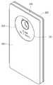
도 13은 본 발명의 일 실시 예에 따른 단말기 케이스의 제2 커버 상태를 나타내는 예시도이다.13 is an exemplary view illustrating a second cover state of the terminal case according to an embodiment of the present invention.
도 13을 참조하면, 단말기(100)와 결합된 단말기 케이스(200)의 케이스 전면부(210)는 단말기(100)의 너비 방향에 위치할 수 있다. 이는 단말기(100)와 결합된 단말기 케이스(200)의 케이스 전면부(210)가 펼쳐진 상태일 수 있다. 이와 같이 단말기(100)와 결합된 단말기 케이스(200)의 케이스 전면부(210)가 단말기(100)의 너비 방향에 위치하는 상태를 이하 "제2 커버 상태"라 한다.13, the case
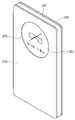
도 14는 본 발명의 일 실시 예에 따른 단말기 케이스의 제3 커버 상태를 나타내는 예시도이다.14 is an exemplary view showing a third cover state of the terminal case according to an embodiment of the present invention.
도 14를 참조하면, 단말기(100)와 결합된 단말기 케이스(200)의 케이스 전면부(210)는 단말기(100)의 후면에 위치할 수 있다. 이는 단말기(100)와 결합된 단말기 케이스(200)의 케이스 전면부(210)가 단말기(100)의 후면 방향으로 젖혀진 상태일 수 있다. 이와 같이 단말기(100)와 결합된 단말기 케이스(200)의 케이스 전면부(210)가 단말기의 후면을 덮는 상태를 이하 "제3 커버 상태"라 한다.Referring to FIG. 14, the case
다시 도 11을 참조한다.Referring again to FIG.
단말기(100)의 제어부(180)는 단말기(100)와 결합된 단말기 케이스(200)의 커버 상태 변화를 인식한다(S130).The
제어부(180)는 센싱부(140)를 통해 단말기 케이스(200)의 커버 상태 변화를 인식할 수 있다. 구체적으로, 제어부(180)는 센싱부(140)에 포함된 자기 센서(145), 근접 센서(141) 중 하나 이상으로부터 단말기 케이스(200)에 대한 센싱값을 획득하고, 획득된 센싱값을 기초로 단말기 케이스(200)의 커버 상태 변화를 인식할 수 있다.The
일 실시 예로, 자기 센서(145)에 포함된 전면 자기 센서(148), 후면 자기 센서(149) 중 하나 이상은 단말기 케이스(200)에 포함된 전면 자성체(231), 후면 자성체(233) 중 하나 이상을 센싱할 수 있다. 제어부(180)는 자기 센서(145)에 포함된 전면 자기 센서(148), 후면 자기 센서(149) 중 하나 이상이 센싱한 센싱값인 자기장의 크기, 자기장 방향 중 하나 이상을 기초로 단말기 케이스(200)의 커버 상태 변화를 인식할 수 있다.One or more of the front
다른 실시 예로, 근접 센서(141)에 포함된 전면센서(148), 후면센서(149) 중 하나 이상은 단말기 케이스(200)의 케이스 전면부(210)에 대응하는 거리를 센싱할 수 있다. 제어부(180)는 근접 센서(141)에 포함된 전면센서(148), 후면센서(149) 중 하나 이상이 센싱한 센싱값인 케이스 전면부(210)에 대응하는 거리를 기초로 단말기 케이스(200)의 커버 상태 변화를 인식할 수 있다.In another embodiment, at least one of the
단말기(100)의 제어부(180)는 판단된 단말기의 상태 및 인식된 단말기 케이스의 상태 변화에 대응하는 동작을 수행한다(S150).The
제어부(180)는 단계 S110에서 판단된 단말기의 상태 및 단계 S130에서 인식된 단말기 케이스의 상태 변화를 기초로 판단된 단말기의 상태 및 인식된 단말기 케이스의 상태 변화에 대응하는 동작을 수행할 수 있다.The
예를 들면, 제어부(180)는 제1 커버 상태에서 제2 커버 상태 또는 제3 커버 상태로 단말기 커버 상태 변화를 인식한 경우, 제1 커버 상태에서 디스플레이부(151)에 표시 중인 화면에 대응하는 동작과 관련된 동작을 수행할 수 있다.For example, when the
다른 예로, 제어부(180)는 제3 커버 상태에서 제2 커버 상태 또는 제3 커버 상태에서 제1 커버 상태로 단말기 커버 상태 변화를 인식한 경우, 제3 커버 상태에서 디스플레이부(151)에 표시 중인 화면에 대응하는 동작과 관련된 동작을 수행할 수 있다.As another example, when the
또 다른 예로, 제어부(180)는 제2 커버 상태에서 제3 커버 상태로 단말기 커버 상태 변화를 인식한 경우, 제2 커버 상태에서 디스플레이부(151)에 표시 중인 화면에 대응하는 동작과 관련된 동작을 수행할 수 있다.As another example, when the
이에 대해 도 15 내지 도 24를 참조하여 상세히 설명한다.This will be described in detail with reference to FIG. 15 to FIG.
도 15는 본 발명의 제1 실시 예에 따른 단말기 동작을 나타내는 흐름도이다.15 is a flowchart illustrating a terminal operation according to the first embodiment of the present invention.
도 15를 참조하면, 단말기(100)의 제어부(180)는 단말기(100)와 결합된 단말기 케이스(200)의 케이스 전면부(210)가 단말기(100)의 전면을 덮고 있는 제1 커버 상태를 인식한다(S211).15, the
제어부(180)는 센싱부(140)를 통해 단말기(100)와 결합된 단말기 케이스(200)의 상태를 인식할 수 있다. 구체적으로 제어부(180)는 자기 센서(145), 근접센서(141) 중 하나 이상을 통해 케이스 전면부(210)의 위치를 인식할 수 있다. 이에 따라 제어부(180)는 단말기(100)와 결합된 단말기 케이스(200)가 제1 커버 상태인지 인식할 수 있다. 이에 대해 상술한 바 있어 자세한 설명은 생략한다.The
또한, 제어부(180)는 제1 커버 상태에서 단말기의 동작 상태를 판단할 수도 있다. 제어부(180)의 단말기의 상태 판단에 대해서는 상술한 바 있어 자세한 설명은 생략한다.Also, the
제어부(180)는 제1 커버 상태에서 디스플레이부(151) 상태를 판단하고(S213), 디스플레이부(151)가 온(On) 상태이면 커버 상태 변화를 감지한다(S231).The
제어부(180)는 제1 커버 상태에서 디스플레이부(151)를 온(On) 할 수 있고, 디스플레이부(151)에 단말기(100)의 동작과 관련된 화면을 표시할 수 있다. 사용자는 제1 커버 상태에서 디스플레이부(151)에 표시되는 화면을 케이스 전면부(210)에 구비된 전면 개구부(270)를 통해 볼 수 있다. 이에 대해 도 16을 참조하여 설명한다.The
도 16은 본 발명의 일 실시 예에 따른 제1 커버 상태에서의 단말기 화면 표시를 나타내는 예시도이다.16 is an exemplary view showing a terminal screen display in a first cover state according to an embodiment of the present invention.
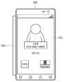
도 16을 참조하면, 제어부(180)는 제1 커버 상태에서 단말기에 수신된 전화와 관련된 전화 수신 화면을 디스플레이부(151)에 표시할 수 있다. 제어부(180)는 디스플레이부(151)의 전체 화면에서 케이스 전면부(210)에 구비된 전면 개구부(270)에 대응하는 위치에만 전화 수신 화면을 표시할 수 있다.Referring to FIG. 16, the
이와 같이, 제어부(180)는 제1 커버 상태에서 디스플레이부(151)를 온 할 수 있으며, 단말기(100)의 동작과 관련된 화면을 디스플레이부(151)에 표시할 수 있다. 상술한 제1 커버 상태에서 전화 수신에 대한 화면 표시에 대한 설명은 설명을 위한 예시로, 제1 커버 상태에서의 단말기 화면 표시는 이에 한정되지 않는다. 따라서, 사용자 또는 설계자의 선택에 따라 다양한 단말기 동작과 관련된 화면이 제1 커버 상태에서 디스플레이부(151)에 표시될 수 있다. 예를 들면, 제어부(180)는 제1 커버 상태에서 동영상 재생, 음악 재생, 메시지 수신, 현재 시간 표시, 날씨 표시 중 하나 이상에 대한 동작과 관련된 화면을 디스플레이부(151)에 표시할 수 있다.In this way, the
한편, 제어부(180)는 제1 커버 상태에서 디스플레이부(151)가 온 상태이면, 단말기(100)와 결합된 단말기 케이스(200)의 상태가 제1 커버 상태에서 다른 커버 상태로 변화되는 것을 인식할 수 있다. 구체적으로 제어부(180)는 제1 커버 상태에서의 센싱부(140)의 센싱값이 변화하면, 단말기(100)와 결합된 단말기 케이스(200)의 상태가 제1 커버 상태에서 다른 커버 상태로 변화되는 것으로 인식할 수 있다. 이에 따라 제어부(180)는 단말기(100)와 결합된 단말기 케이스(200)가 제1 커버 상태에서 다른 커버 상태로 커버 상태가 변화하는 것을 감지할 수 있다.When the
제어부(180)는 감지된 커버 상태가 제2 커버 상태이면(S233), 제1 커버 상태에서 디스플레이부(151)에 표시되던 화면에 대응하는 제1 동작을 수행한다(S251).If the detected cover state is the second cover state (S233), the
제어부(180)는 센싱부(140)의 센싱값을 기초로 변화된 커버 상태를 판단할 수 있다. 이에 대해서는 상술한 바 있으므로 자세한 설명은 생략한다.The
제어부(180)는 센싱부(140)의 센싱값을 기초로 단말기(100)와 결합된 단말기 케이스(200)의 상태가 제1 커버 상태에서 제2 커버 상태로 변화된 것으로 판단하면, 기 설정된 제1 동작을 수행할 수 있다. 기 설정된 제1 동작은 사용자 또는 설계자의 설정에 따라 다양한 동작이 설정될 수 있다.When the
제어부(180)는 제1 커버 상태에서 디스플레이부(151)에 표시되던 화면에 대응하는 단말기의 동작 중 간단한 조작이 필요한 제1 동작을 수행할 수 있다. 여기서 간단한 조작은 기준 횟수 이하의 사용자 입력이 필요한 조작을 의미할 수 있다.The
일 실시 예를 도 17을 참조하여 설명한다.One embodiment will be described with reference to Fig.
도 17은 본 발명의 일 실시 예에 따른 전화 수신 화면에 대응하는 제1 동작을 나타내는 예시도이다.17 is an exemplary diagram showing a first operation corresponding to a telephone receiving screen according to an embodiment of the present invention.
도 17을 참조하면, 제어부(180)는 제1 커버 상태에서 디스플레이부(151)에 표시되던 전화 수신 화면에 대응하는 제1 동작으로 전화 수신 여부에 대한 사용자 입력 화면을 표시할 수 있다. 이에 따라 제어부(180)는 전화 수신 또는 전화 거부에 대한 사용자 입력을 획득할 수 있다.Referring to FIG. 17, the
다른 실시 예로, 제어부(180)는 제1 커버 상태에서 디스플레이부(151)에 표시되던 화면이 시계 표시 화면이면, 이에 대응하는 제1 동작으로 사용자의 일정을 디스플레이부(151)에 표시할 수 있다.In another embodiment, if the screen displayed on the
또 다른 실시 예로, 제어부(180)는 제1 커버 상태에서 디스플레이부(151)에 표시되던 화면이 날씨 표시 화면이면, 이에 대응하는 제1 동작으로 일정 시간 간격 별 날씨를 디스플레이부(151)에 표시할 수 있다.In another embodiment, when the screen displayed on the
또 다른 실시 예로, 제어부(180)는 제1 커버 상태에서 디스플레이부(151)에 표시되던 화면이 메시지 표시 화면이면, 이에 대응하는 제1 동작으로 메시지에 포함된 링크 주소에 접속하는 동작을 수행할 수 있다.In another embodiment, when the screen displayed on the
또 다른 실시 예로, 제어부(180)는 제1 커버 상태에서 디스플레이부(151)에 표시되던 화면이 음악 재생 화면이면, 이에 대응하는 제1 동작으로 재생 중인 곡과 관련된 컨텐트를 검색하는 접속하는 동작을 수행할 수 있다.In another embodiment, if the screen displayed on the
또 다른 실시 예로, 제어부(180)는 제1 커버 상태에서 디스플레이부(151)에 표시되던 화면이 사진 촬영 화면이면, 이에 대응하는 제1 동작으로 촬영 중인 사진 또는 촬영된 사진을 편집하기 위한 메뉴를 디스플레이부(151)에 표시하는 동작을 수행할 수 있다.In another embodiment, if the screen displayed on the
또한, 제어부(180)는 제1 커버 상태에서 디스플레이부(151)에 표시되던 화면에 대응하는 단말기의 동작 중 기준 횟수 이하의 사용자 입력이 필요한 메뉴를 표시하는 제1 화면을 표시할 수도 있다.In addition, the
일 실시 예를 도 18을 참조하여 설명한다.One embodiment will be described with reference to Fig.
도 18은 본 발명의 일 실시 예에 따른 전화 종료 화면에 대응하는 제1 화면을 나타내는 예시도이다.18 is an exemplary view showing a first screen corresponding to a call termination screen according to an embodiment of the present invention.
도 18을 참조하면, 제어부(180)는 제1 커버 상태에서 디스플레이부(151)에 표시되던 전화 종료 화면에 대응하는 제1 화면으로, 종료된 전화와 관련된 동작을 수행하기 위한 하나 이상의 메뉴를 디스플레이부(151)에 표시할 수 있다. 예를 들면, 제어부(180)는 제1 화면에 제1 윈도우(310)를 표시할 수 있다. 제1 윈도우(310)는 기준 횟수 이하의 사용자 입력이 필요한 메뉴인 연락처(311), 전화(312), 검색(313)에 대한 메뉴를 포함할 수 있다. 이에 따라 제어부(180)는 제1 윈도우(310)에 표시된 메뉴 중 하나를 선택하는 사용자 입력을 획득하면, 획득된 사용자 입력에 대응하는 메뉴를 실행할 수 있다. 그리고 제어부(180)는 실행된 메뉴에 따라 종료된 전화와 관련된 동작을 수행할 수 있다.Referring to FIG. 18, the
상술한 제1 동작에 대한 설명은 설명을 위한 예시로 이에 한정되지 않으며, 제1 동작은 사용자 또는 설계자의 선택에 따라 다양하게 설정될 수 있다.The description of the first operation is not intended to be limiting, and the first operation may be variously set according to the choice of the user or the designer.
다시 도 15를 참조한다.Referring back to FIG.
제어부(180)는 감지된 커버 상태가 제3 커버 상태이면(S233), 제1 커버 상태에서 디스플레이부(151)에 표시되던 화면에 대응하는 제2 동작을 수행한다(S252).If the detected cover state is the third cover state (S233), the
제어부(180)는 센싱부(140)의 센싱값을 기초로 변화된 커버 상태를 판단할 수 있다. 이에 대해서는 상술한 바 있으므로 자세한 설명은 생략한다.The
제어부(180)는 센싱부(140)의 센싱값을 기초로 단말기(100)와 결합된 단말기 케이스(200)의 상태가 제1 커버 상태에서 제3 커버 상태로 변화된 것으로 판단하면, 기 설정된 제2 동작을 수행할 수 있다. 기 설정된 제2 동작은 사용자 또는 설계자의 설정에 따라 다양한 동작이 설정될 수 있다.When the
일 실시 예로, 제어부(180)는 제1 커버 상태에서 디스플레이부(151)에 표시되던 화면에 대응하는 단말기의 동작 중 복잡한 조작이 필요한 제2 동작을 수행할 수 있다. 여기서 복잡한 조작은 기준 횟수 초과의 사용자 입력이 필요한 조작을 의미할 수 있다.In one embodiment, the
일 실시 예를 도 19를 참조하여 설명한다.One embodiment will be described with reference to Fig.
도 19는 본 발명의 일 실시 예에 따른 전화 종료 화면에 대응하는 제2 화면을 나타내는 예시도이다.19 is a diagram illustrating an example of a second screen corresponding to a call termination screen according to an embodiment of the present invention.
도 19를 참조하면, 제어부(180)는 제1 커버 상태에서 디스플레이부(151)에 표시되던 전화 종료 화면에 대응하는 제2 화면으로, 종료된 전화와 관련된 동작을 수행하기 위한 하나 이상의 메뉴를 디스플레이부(151)에 표시할 수 있다. 예를 들면, 제어부(180)는 제2 화면으로 디스플레이부(151)에 복수의 메뉴인 연락처(311), 전화(312), 메시지(314), 검색(313), 이메일(315)에 대한 메뉴를 표시할 수 있다. 이에 따라 제어부(180)는 디스플레이부(151)에 표시된 메뉴 중 하나를 선택하는 사용자 입력을 획득하면, 획득된 사용자 입력에 대응하는 메뉴를 실행할 수 있다. 그리고 제어부(180)는 실행된 메뉴에 따라 종료된 전화와 관련된 동작을 수행할 수 있다.Referring to FIG. 19, the
한편, 제어부(180)는 제2 동작으로 제1 커버 상태에서 디스플레이부(151)에 표시되던 화면과 관련된 동작을 수행할 수도 있다.Meanwhile, the
일 실시 예로 도 20을 참조하여 설명한다.One embodiment will be described with reference to Fig.
도 20은 본 발명의 일 실시 예에 따른 전화 수신 화면에 대응하는 제2 동작을 나타내는 예시도이다.20 is an exemplary diagram showing a second operation corresponding to a telephone reception screen according to an embodiment of the present invention.
도 20을 참조하면, 제어부(180)는 제1 커버 상태에서 디스플레이부(151)에 표시되던 전화 수신 화면에 대응하는 제2 동작으로 수신된 전화를 수신할 수 있다. 이에 따라 제어부(180)는 별도의 사용자 입력 획득 없이, 수신된 전화에 대응하는 상대방과의 통화모드로 동작할 수 있다.Referring to FIG. 20, the
다른 실시 예로, 제어부(180)는 제1 커버 상태에서 디스플레이부(151)에 표시되던 화면이 시계 표시 화면이면, 이에 대응하는 제2 동작으로 시계 애플리케이션을 실행할 수 있다.In another embodiment, if the screen displayed on the
또 다른 실시 예로, 제어부(180)는 제1 커버 상태에서 디스플레이부(151)에 표시되던 화면이 날씨 표시 화면이면, 이에 대응하는 제2 동작으로 날씨 애플리케이션을 실행할 수 있다.In another embodiment, if the screen displayed on the
또 다른 실시 예로, 제어부(180)는 제1 커버 상태에서 디스플레이부(151)에 표시되던 화면이 메시지 표시 화면이면, 이에 대응하는 제2 동작으로 메시지 애플리케이션을 실행할 수 있다.In another embodiment, if the screen displayed on the
상술한 제2 동작에 대한 설명은 설명을 위한 예시로 이에 한정되지 않으며, 제2 동작은 사용자 또는 설계자의 선택에 따라 다양하게 설정될 수 있다.The description of the second operation is not limited thereto, and the second operation may be variously set according to the selection of the user or the designer.
제어부(180)는 제1 커버 상태에서 디스플레이부(151) 상태를 판단하고(S213), 디스플레이부(151)가 오프(Off) 상태이면 커버 상태 변화를 감지한다(S232).The
제어부(180)는 제1 커버 상태에서 디스플레이부(151)가 오프 상태이면, 센싱부(140)의 센싱값을 기초로 단말기(100)와 결합된 단말기 케이스(200)의 상태가 제1 커버 상태에서 다른 커버 상태로 변화되는지 인식할 수 있다. 구체적으로 제어부(180)는 제1 커버 상태에서의 센싱부(140)의 센싱값이 변화하면, 단말기(100)와 결합된 단말기 케이스(200)의 상태가 제1 커버 상태에서 다른 커버 상태로 변화되는 것으로 인식할 수 있다. 이에 따라 제어부(180)는 단말기(100)와 결합된 단말기 케이스(200)가 제1 커버 상태에서 다른 커버 상태로 커버 상태가 변화하는 것을 감지할 수 있다.The
제어부(180)는 감지된 커버 상태가 제2 커버 상태이면(S234), 기 설정된 제3 동작을 수행한다(S253).If the detected cover state is the second cover state (S234), the
제어부(180)는 센싱부(140)의 센싱값을 기초로 단말기(100)와 결합된 단말기 케이스(200)의 상태가 제1 커버 상태에서 제2 커버 상태로 변화된 것으로 판단하면, 기 설정된 제3 동작을 수행할 수 있다. 기 설정된 제3 동작은 사용자 또는 설계자의 설정에 따라 다양한 동작이 설정될 수 있다.If the
일 실시 예로, 제3 동작은 현재 시각과 관련된 이벤트를 표시하는 동작일 수 있다. 이에 따라 제어부(180)는 기 설정된 제3 동작으로 현재 시각과 관련된 하나 이상의 이벤트를 표시하는 이벤트 윈도우인 제2 윈도우(350)를 디스플레이부(151)에 표시할 수 있다. 여기서 현재 시각과 관련된 이벤트는 사용자의 일정, 알람, 해야 할 일, 부재중 수신된 전화, 부재중 수신된 메시지 중 하나 이상에 대한 이벤트일 수 있다. 여기서 이벤트는 기 설정된 이벤트일 수 있다. 이에 따라 제어부(180)는 특정 상대방, 특정 애플리케이션에 대한 이벤트를 이벤트 윈도우인 제2 윈도우(350)에 표시할 수도 있다.In one embodiment, the third action may be an action indicating an event associated with the current time. Accordingly, the
이에 대해 도 21을 참조하여 설명한다.This will be described with reference to FIG.
도 21은 본 발명의 일 실시 예에 따른 단말기의 제3 동작에 따른 제2 윈도우 표시에 대한 예시도이다.FIG. 21 is a diagram illustrating an example of a second window display according to a third operation of a terminal according to an embodiment of the present invention. FIG.
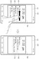
도 21을 참조하면, 제어부(180)는 제2 커버 상태에서 현재 시각과 관련된 하나 이상의 이벤트를 표시하는 제2 윈도우(350)를 디스플레이부(151)에 표시할 수 있다. 예를 들면, 제어부(180)는 제2 윈도우(350)에 현재 시각인 오후 2시 32분과 관련된 하나 이상의 이벤트로 오후 3시에 있을 컨퍼런스에 대한 일정과 관련된 제1 이벤트(351), 수신하지 못한 제이슨 킴으로부터의 부재중 전화와 관련된 제2 이벤트(352), 해야 할 일인 폴에게 파티 초대 메일 보내기와 관련된 제3 이벤트(353)를 표시할 수 있다.Referring to FIG. 21, the
한편, 제어부(180)는 디스플레이부(151)에 표시된 제2 윈도우(350)에 대한 사용자 입력을 획득하면, 획득된 사용자 입력에 대응하는 동작을 수행할 수도 있다.On the other hand, the
이에 대해 도 22 내지 도 24를 참조하여 설명한다.This will be described with reference to FIGS. 22 to 24. FIG.
도 22는 본 발명의 일 실시 예에 따른 제2 윈도우에 대한 편집 동작을 나타내는 예시도이다.22 is an exemplary diagram illustrating an editing operation for a second window according to an embodiment of the present invention.
도 22를 참조하면, 제어부(180)는 디스플레이부(151)에 표시된 제2 윈도우(350)에 포함된 복수의 이벤트인 제1 이벤트 내지 제3 이벤트(351, 352, 353) 중 제1 이벤트(351)에 대응하는 영역을 왼쪽 방향으로 스와이프하는 사용자 입력을 획득할 수 있다. 이에 따라 제어부(180)는 표시된 제2 윈도우(350)에서 제1 이벤트(351)를 삭제할 수 있다. 그래서 제어부(180)는 표시된 제2 윈도우(350)에 제2 이벤트(352), 제3 이벤트(353)를 표시할 수 있다.Referring to FIG. 22, the
도 23은 본 발명의 일 실시 예에 따른 제2 윈도우에 따른 이벤트 실행 동작을 나타내는 예시도이다.23 is an exemplary diagram illustrating an event execution operation according to a second window according to an embodiment of the present invention.
도 23을 참조하면, 제어부(180)는 디스플레이부(151)에 표시된 제2 윈도우(350)에 포함된 복수의 이벤트인 제1 이벤트 내지 제3 이벤트(351, 352, 353) 중 제2 이벤트(352)에 대응하는 영역을 오른쪽 방향으로 스와이프하는 사용자 입력을 획득할 수 있다. 이에 따라 제어부(180)는 제2 이벤트에 대응하는 동작을 수행할 수 있다. 그래서 제어부(180)는 제2 이벤트인 부재중 전화에 대응하는 상대방에게 전화를 발신할 수 있다.Referring to FIG. 23, the
도 24는 본 발명의 일 실시 예에 따른 제2 윈도우에 대한 이벤트 추가 동작을 나타내는 예시도이다.24 is an exemplary diagram illustrating an event adding operation for a second window according to an embodiment of the present invention.
도 24를 참조하면, 제어부(180)는 디스플레이부(151)에 제2 윈도우(350) 및 이벤트 추가 아이콘(359)를 표시할 수 있다. 제어부(180)는 이벤트 추가 아이콘(359)에 대한 사용자 입력을 획득하면, 제2 윈도우(350)에 표시될 이벤트를 추가하는 사용자 입력을 획득할 수 있다. 그리고 제어부(180)는 추가된 이벤트를 제2 윈도우(350)에 표시할 수 있다.Referring to FIG. 24, the
상술한 설명 이외에도 제어부(180)는 제2 윈도우(350)에 대한 사용자 입력을 기초로 제2 윈도우(350)에 포함된 복수의 이벤트의 표시 순서를 편집할 수 있다. 또한, 제어부(180)는 사용자 설정에 따라 제2 윈도우(350)에 표시되는 복수의 이벤트에 대한 글자 크기, 폰트, 색상 등을 변경할 수도 있다.The
상술한 제3 동작에 대한 설명은 설명을 위한 예시로 이에 한정되지 않는다. 따라서 사용자 또는 설계자의 선택에 따라 다양한 동작이 설정될 수 있다.The description of the third operation described above is for illustrative purposes only, and is not limited thereto. Therefore, various operations can be set according to the selection of the user or the designer.
다시 도 15를 참조한다.Referring back to FIG.
제어부(180)는 감지된 커버 상태가 제3 커버 상태이면(S234), 기 설정된 제4 동작을 수행한다(S253).If the detected cover state is the third cover state (S234), the
제어부(180)는 센싱부(140)의 센싱값을 기초로 단말기(100)와 결합된 단말기 케이스(200)의 상태가 제1 커버 상태에서 제3 커버 상태로 변화된 것으로 판단하면, 기 설정된 제4 동작을 수행할 수 있다. 기 설정된 제4 동작은 사용자 또는 설계자의 설정에 따라 다양한 동작이 설정될 수 있다.If the
일 실시 예로, 제4 동작은 단말기(100)의 기본 화면을 표시하는 동작일 수 있다. 이에 따라 제어부(180)는 기 설정된 제4 동작으로, 단말기의 기본 화면을 디스플레이부(151)에 표시하는 동작을 수행할 수 있다. 여기서 단말기의 기본 화면은 홈(Home) 화면일 수 있다.In one embodiment, the fourth operation may be an operation of displaying the basic screen of the terminal 100. [ Accordingly, the
다른 실시 예로, 제4 동작은 단말기(100)가 이전에 수행하던 동작에 따른 화면을 표시하는 동작일 수 있다. 여기서 단말기(100)가 이전에 수행하던 동작은 단말기의 상태가 제1 커버 상태 이전의 제2 커버 상태 또는 제3 커버 상태에서 수행하던 동작일 수 있다. 이에 따라 제어부(180)는 기 설정된 제4 동작으로, 단말기(100)가 이전에 수행하던 동작에 따른 화면을 디스플레이부(151)에 표시하는 동작을 수행할 수 있다. 예를 들어, 제어부(180)가 단계 S211의 제1 커버 상태 이전의 제3 커버 상태에서 웹 페이지를 디스플레이부(151)에 표시하고 있었던 경우, 기 설정된 제4 동작으로 웹 페이지를 디스플레이부(151)에 표시하는 동작을 수행할 수 있다.In another embodiment, the fourth operation may be an operation of displaying a screen according to an operation previously performed by the
상술한 제4 동작에 대한 설명은 설명을 위한 예시로 이에 한정되지 않는다. 따라서 사용자 또는 설계자의 선택에 따라 다양한 동작이 설정될 수 있다.The description of the fourth operation described above is for illustrative purposes only, and is not limited thereto. Therefore, various operations can be set according to the selection of the user or the designer.
한편, 본 발명에 따른 단말기(100)는 단말기(100)와 결합된 단말기 케이스(200)의 상태가 제2 커버 상태 또는 제3 커버 상태에서 다른 커버 상태로 변화되면, 기 설정된 제5 동작을 수행할 수 있다. 이에 대해 도 25 내지 도 27을 참조하여 설명한다.Meanwhile, the terminal 100 according to the present invention performs a predetermined fifth operation when the state of the
도 25는 본 발명의 제2 실시 예에 따른 단말기 동작을 나타내는 흐름도이다.25 is a flowchart illustrating a terminal operation according to a second embodiment of the present invention.
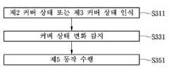
도 25를 참조하면, 단말기(100)의 제어부(180)는 단말기와 결합된 단말기 케이스(200)의 상태를 제2 커버 상태 또는 제3 커버 상태로 인식한다(S311).Referring to FIG. 25, the
제어부(180)는 센싱부(140)의 센싱값을 기초로 단말기(100)와 결합된 단말기 케이스(200)의 상태를 인식할 수 있다. 구체적으로 제어부(180)는 자기 센서(145), 근접센서(141) 중 하나 이상의 센싱값을 기초로 케이스 전면부(210)의 위치를 인식할 수 있다. 이에 따라 제어부(180)는 단말기(100)와 결합된 단말기 케이스(200)가 제2 커버 상태 또는 제3 커버 상태인지 인식할 수 있다. 이에 대해 상술한 바 있어 자세한 설명은 생략한다.The
제어부(180)는 제2 커버 상태 또는 제3 커버 상태에서 단말기 케이스(200)의 상태 변화를 감지한다(S331).The
제어부(180)는 센싱부(140)의 센싱값을 기초로 단말기(100)와 결합된 단말기 케이스(200)의 상태가 제2 커버 상태 또는 제3 커버 상태에서 다른 커버 상태로 변화되는지 인식할 수 있다. 예를 들면 제어부(180)는 센싱부(140)의 센싱값을 기초로 단말기 케이스(200)의 상태가 제3 커버 상태에서 제2 커버 상태, 제3 커버 상태에서 제1 커버 상태, 제2 커버 상태에서 제1 커버 상태 및 제2 커버 상태에서 제3 커버 상태 중 하나의 상태로 변화되는지 인식할 수 있다. 이에 따라 제어부(180)는 단말기(100)와 결합된 단말기 케이스(200)가 제2 커버 상태 또는 제3 커버 상태에서 다른 커버 상태로 커버 상태가 변화하는 것을 감지할 수 있다.The
제어부(180)는 커버 상태 변화를 감지하면, 기 설정된 제5 동작을 수행한다(S351).When the
제어부(180)는 센싱부(140)의 센싱값을 기초로 단말기(100)와 결합된 단말기 케이스(200)의 상태가 제2 커버 상태 또는 제3 커버 상태에서 다른 커버 상태로 변화된 것으로 판단하면, 기 설정된 제5 동작을 수행할 수 있다. 기 설정된 제5 동작은 사용자 또는 설계자의 설정에 따라 다양한 동작이 설정될 수 있다.If the
일 실시 예로, 제5 동작은 단말기(100)의 사용 내역, 미확인 이벤트 중 하나 이상을 포함하는 요약 정보에 대한 요약 정보 윈도우인 제3 윈도우(370)를 표시하는 동작일 수 있다. 여기서 단말기(100)의 사용 내역은 단말기(100)의 커버 상태가 제1 커버 상태에서 제2 커버 상태 또는 제3 커버 상태로 변화된 후, 단말기(100)의 동작 내역을 포함할 수 있다. 이에 대해 도 26을 참조하여 설명한다.In one embodiment, the fifth operation may be an operation to display a
도 26은 본 발명의 일 실시 예에 따른 제3 윈도우 표시에 대한 예시도이다.26 is an exemplary view of a third window display according to an embodiment of the present invention.
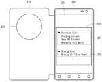
도 26을 참조하면, 제어부(180)는 단말기(100)의 사용 내역(371), 미확인 이벤트(372)를 포함하는 요약 정보에 대한 제3 윈도우(370)을 디스플레이부(151)에 표시할 수 있다. 구체적으로 제어부(180)는 제3 윈도우(370)의 일부 영역에 단말기(100)의 커버 상태가 제1 커버 상태에서 제2 커버 상태 또는 제1 커버 상태에서 제3 커버 상태로 변화된 후의 단말기(100)의 사용 내역(371)으로 <메일 확인>, <캘린더 열기>, <메리에게 메시지 보내기>를 표시할 수 있다. 또한, 제어부(180)는 제3 윈도우(370)의 다른 일부 영역에 미확인 이벤트(372)인 <한나로부터 부재중 전화>를 표시할 수 있다.26, the
한편, 제어부(180)는 디스플레이부(151)에 표시된 제3 윈도우(370)에 대한 사용자 입력을 획득하면, 획득된 사용자 입력에 대응하는 동작을 수행할 수도 있다.Meanwhile, when the
이에 대해 도 27을 참조하여 설명한다.This will be described with reference to FIG.
도 27은 본 발명의 일 실시 예에 따른 제3 윈도우에 따른 이벤트 실행 동작을 나타내는 예시도이다.27 is an exemplary diagram illustrating an event execution operation according to a third window according to an embodiment of the present invention.
도 27을 참조하면, 제어부(180)는 디스플레이부(151)에 표시된 제3 윈도우(370)에 포함된 사용 내역(371), 미확인 이벤트(372) 중 하나에 대응하는 영역을 터치하는 사용자 입력을 획득할 수 있다. 예를 들면, 제어부(180)는 제3 윈도우(370)에 포함된 사용 내역(371), 미확인 이벤트(372) 중 사용 내역(371)에 포함된 하나의 이벤트인 <한나로부터 부재중 전화>에 대응하는 영역을 터치하는 사용자 입력을 획득할 수 있다. 이에 따라 제어부(180)는 터치 입력에 대응하는 이벤트로, 한나에게 전화를 발신할 수 있다.27, the
도 28은 본 발명의 다른 실시 예에 따른 제3 윈도우에 따른 이벤트 실행 동작을 나타내는 예시도이다.28 is an exemplary diagram illustrating an event execution operation according to a third window according to another embodiment of the present invention.
도 28을 참조하면, 제어부(180)는 디스플레이부(151)에 표시된 제3 윈도우(370)에 포함된 사용 내역(371), 미확인 이벤트(372) 중 하나에 대응하는 영역을 터치하는 사용자 입력을 획득할 수 있다. 예를 들면, 제어부(180)는 제3 윈도우(370)에 포함된 사용 내역(371), 미확인 이벤트(372) 중 미확인 이벤트(372)인 <캘린더 열기>에 대응하는 영역을 터치하는 사용자 입력을 획득할 수 있다. 이에 따라 제어부(180)는 터치 입력에 대응하는 이벤트로, 캘린더 창(375)를 디스플레이부(151)에 표시할 수 있다.28, the
상술한 제5 동작에 대한 설명은 설명을 위한 예시로 이에 한정되지 않는다. 따라서 사용자 또는 설계자의 선택에 따라 다양한 동작이 설정될 수 있다.The description of the fifth operation described above is for illustrative purposes only, and is not limited thereto. Therefore, various operations can be set according to the selection of the user or the designer.
한편, 본 발명에 따른 단말기(100)는 단말기(100)의 전면과 단말기(100)와 결합된 단말기 케이스(200)의 케이스 전면부(210) 간의 거리를 측정할 수 있다. 제어부(180)는 측정된 거리인 측정 거리(d)가 제1 기준 거리(d1)와 제2 기준 거리(d2) 사이에서 머무른 시간인 유지시간(td)을 측정할 수 있다. 그리고 제어부(180)는 측정된 유지시간(td)에 대응하는 동작을 수행할 수 있다.Meanwhile, the terminal 100 according to the present invention can measure the distance between the front surface of the terminal 100 and the case
이에 대해 도 29 내지 도 39를 참조하여 설명한다.This will be described with reference to Figs. 29 to 39. Fig.
도 29는 본 발명의 제3 실시 예에 따른 단말기 동작을 나타내는 흐름도이다.29 is a flowchart illustrating a terminal operation according to a third embodiment of the present invention.
도 29를 참조하면, 단말기(100)의 제어부(180)는 단말기(100)와 결합된 단말기 케이스(200)의 케이스 전면부(210)와 단말기(100)의 전면 간의 거리(d)를 측정한다(S410).29, the
제어부(180)는 센싱부(140)의 센싱값을 기초로 케이스 전면부(210)와 단말기(100)의 전면 간의 거리(d)를 측정할 수 있다. 구체적으로 제어부(180)는 센싱부(140)에 포함된 자기 센서(145), 근접센서(141) 중 하나 이상의 센싱값을 기초로 측정 거리(d)를 측정할 수 있다.The
일 실시 예로, 자기 센서(145)는 케이스 전면부(210)에 포함된 전면 자성체(231)에 대응하는 자기장의 크기, 자기장 방향 중 하나 이상을 감지할 수 있다. 제어부(180)는 감지된 전면 자성체(231)에 대응하는 자기장의 크기, 자기장 방향 중 하나 이상을 기준값과 비교하고, 비교 결과를 기초로 케이스 전면부(210)와 단말기(100)의 전면 간의 거리(d)를 측정할 수 있다.In one embodiment, the
다른 실시 예로, 근접센서(141)에 포함된 전면센서(148)는 단말기(100)의 전면 방향에 대해 센싱할 수 있다. 전면센서(148)는 케이스 전면부(210)까지의 거리를 센싱할 수 있다. 제어부(180)는 전면센서(148)의 센싱값을 기초로 케이스 전면부(210)와 단말기(100)의 전면 간의 거리(d)를 측정할 수 있다.In another embodiment, the
제어부(180)는 측정된 케이스 전면부(210)와 단말기(100)의 전면 간의 측정 거리(d)가 제1 기준 거리(d1) 이상이고, 제2 기준 거리(d2) 이하인지 판단한다(S430).The
이에 대해 도 30을 참조하여 설명한다.This will be described with reference to FIG.
도 30은 본 발명의 일 실시 예에 따른 측정 거리, 제1 기준 거리 및 제2 기준 거리를 나타내는 예시도이다.30 is an exemplary view showing a measurement distance, a first reference distance, and a second reference distance according to an embodiment of the present invention.
도 30을 참조하면, 제어부(180)는 측정 거리(d)가 기 설정된 제1 기준 거리(d1) 이상이고, 제2 기준 거리(d2) 이하인지 판단할 수 있다. 여기서 제1 기준 거리(d1)은 제2 기준 거리(d2)보다 짧은 거리이다. 구체적으로 제어부(180)는 측정된 측정 거리(d)에 대한 거리 값이 제1 기준 거리(d1)에 대한거리 값보다 큰 지 판단할 수 있다. 그리고 제어부(180)는 측정된 측정 거리(d)에 대한 거리 값이 제2 기준 거리(d2)에 대한거리 값보다 작은 지 판단할 수 있다. 이에 따라 제어부(180)는 판단 결과를 기초로 측정 거리(d)가 기 설정된 제1 기준 거리(d1) 이상이고, 제2 기준 거리(d2) 이하인지 판단할 수 있다.Referring to FIG. 30, the
상술한 제1 기준 거리(d1), 제2 기준 거리(d2)는 사용자 또는 설계자의 선택에 따라 설정될 수 있다.The first reference distance d1 and the second reference distance d2 may be set according to the user or designer's selection.
다시 도 29를 참조한다.See FIG. 29 again.
제어부(180)는 측정 거리(d)가 제1 기준 거리(d1) 이상이고, 제2 기준 거리(d2) 이하인 시간인 유지시간(td)를 측정한다(S450).The
여기서 유지시간(td)는측정 거리(d)가 제1 기준 거리(d1)과 제2 기준 거리(d2) 사이에서 유지되는 시간을 의미할 수 있다. 일 실시 예로, 제어부(180)는 측정 거리(d)가 제1 기준 거리(d1) 이상인 시점(t1)부터 제2 기준 거리(d2) 미만인 시점(t2)까지의 유지시간(td)을 측정할 수 있다. 다른 실시 예로, 제어부(180)는 측정 거리(d)가 제1 기준 거리(d1) 이상인 시점(t1)부터 제2 기준 거리(d2) 초과인 시점(t3)까지의 유지시간(td)을 측정할 수 있다.Here, the holding time td is Can mean the time at which the measurement distance d is maintained between the first reference distance d1 and the second reference distance d2 . An exemplary example, the
제어부(180)는 제1 커버 상태에서 디스플레이부(151)에 표시되는 화면에 대응하는 단말기(100)의 동작을 판단한다(S470).The
제어부(180)는 단말기(100)와 결합된 단말기 케이스(200)의 상태가 제1 커버 상태일 때, 디스플레이부(151)에 표시되는 화면에 대응하는 단말기(100)의 동작을 판단할 수 있다.The
구체적으로, 제어부(180)는 제1 커버 상태에서 디스플레이부(151)를 온(On) 할 수 있으며, 단말기(100)의 동작과 관련된 화면을 디스플레이부(151)에 표시할 수 있다. 예를 들면, 제어부(180)는 제1 커버 상태에서 동영상 재생, 음악 재생, 메시지 수신, 현재 시간 표시, 날씨 표시 중 하나 이상에 대한 동작과 관련된 화면을 디스플레이부(151)에 표시할 수 있다. 제1 커버 상태에서 디스플레이부(151)에 표시되는 화면에 대응하는 동작에 대해서는 상술한 바 있어, 자세한 설명은 생략한다.Specifically, the
이에 따라 제어부(180)는 제1 커버 상태에서 디스플레이부(151)에 표시되는 화면에 대응하는 동작을 판단할 수 있다. 예를 들면 제어부(180)는 제1 커버 상태에서 디스플레이부(151)에 메시지 수신과 관련된 화면을 표시하면, 단말기(100)의 동작이 메시지와 관련된 동작 중인 것으로 판단할 수 있다. 다른 예를 들면, 제어부(180)는 제1 커버 상태에서 디스플레이부(151)에 날씨 표시와 관련된 화면을 표시하면, 단말기(100)의 동작이 날씨와 관련된 동작 중인 것으로 판단할 수 있다. 이와 ??아, 제어부(180)는 제1 커버 상태에서 디스플레이부(151)에 표시되는 화면에 대응하는 동작을 판단할 수 있다.Accordingly, the
제어부(180)는 판단된 단말기(100)의 동작 및 측정된 유지시간(td)에 대응하는 동작을 수행한다(S490).The
제어부(180)는 단계 S470에서 판단된 단말기(100)의 동작 및 측정된 유지시간(td)에 대응하는 동작을 수행할 수 있고, 판단된 단말기(100)의 동작 및 측정된 유지시간(td)에 대응하는 동작은 기 설정된 동작일 수 있다.The
이에 대해 도 31 내지 도 39를 참조하여 설명한다.This will be described with reference to FIG. 31 to FIG.
도 31 내지 도 32는 본 발명의 일 실시 예에 따른 전화 수신 화면에 대응하는 단말기의 동작을 나타내는 예시도이다.31 to 32 are exemplary diagrams illustrating operations of a terminal corresponding to a telephone receiving screen according to an embodiment of the present invention.
제어부(180)는 판단된 단말기(100)의 동작이 전화 수신 동작이면, 전화 수신과 관련된 동작을 판단된 단말기(100)의 동작 및 측정된 유지시간(td)에 대응하는 동작으로 수행할 수 있다. 일 실시 예로, 도 31에 도시된 바와 같이, 제어부(180)는 판단된 단말기(100)의 동작이 전화 수신 동작이고, 측정된 유지시간(td)이 제1 시간이면, 1분 간 무음벨 상태로 동작할 수 있다. 이에 따라 제어부(180)는 디스플레이부(151)에 무음벨 표시 및 무음 동작 시간인 1분을 표시할 수 있다. 다른 실시 예로, 도 32에 도시된 바와 같이, 제어부(180)는 판단된 단말기(100)의 동작이 전화 수신 동작이고, 측정된 유지시간(td)이 제5 시간이면, 5분 간 무음벨 상태로 동작할 수 있다. 이에 따라 제어부(180)는 디스플레이부(151)에 무음벨 표시 및 무음 동작 시간인 5분을 표시할 수 있다.If the determined operation of the terminal 100 is a telephone receiving operation, the
도 33 내지 도 34는 본 발명의 일 실시 예에 따른 시계 화면에 대응하는 단말기의 동작을 나타내는 예시도이다.33 to 34 are diagrams illustrating an operation of a terminal corresponding to a clock screen according to an embodiment of the present invention.
제어부(180)는 제1 커버 상태에서 디스플레이부(151)에 현재 시간을 나타내는 시계 화면을 표시할 수 있고, 표시된 시계 화면에 대응하는 단말기(100)의 동작으로 시간과 관련된 동작을 판단된 단말기(100)의 동작 및 측정된 유지시간(td)에 대응하는 동작으로 수행할 수 있다. 일 실시 예로, 도 33에 도시된 바와 같이, 제어부(180)는 판단된 단말기(100)의 동작이 시계 표시 동작이고, 측정된 유지시간(td)이 제3 시간이면, 30분 후 알람하도록 알람을 설정할 수 있다. 이에 따라 제어부(180)는 디스플레이부(151)에 30분 후 알람 표시를 표시할 수 있고, 설정된 30분 후 알람 동작할 수 있다. 다른 실시 예로, 도 34에 도시된 바와 같이, 제어부(180)는 판단된 단말기(100)의 동작이 시계 표시 동작이고, 측정된 유지시간(td)이 제7 시간이면, 2시간 후 알람하도록 알람을 설정할 수 있다. 이에 따라 제어부(180)는 디스플레이부(151)에 2시간 후 알람 표시를 표시할 수 있고, 설정된 2시간 후 알람 동작할 수 있다.The
도 35 내지 도 37은 본 발명의 일 실시 예에 따른 날씨 화면에 대응하는 단말기의 동작을 나타내는 예시도이다.35 to 37 are views illustrating exemplary operations of a terminal corresponding to a weather screen according to an embodiment of the present invention.
도 35를 참조하면, 제어부(180)는 제1 커버 상태에서 디스플레이부(151)에 현재 날씨를 나타내는 날씨 화면을 표시할 수 있고, 표시된 날씨 화면에 대응하는 단말기(100)의 동작으로 날씨와 관련된 동작을 판단된 단말기(100)의 동작 및 측정된 유지시간(td)에 대응하는 동작으로 수행할 수 있다. 일 실시 예로, 도 36에 도시된 바와 같이, 제어부(180)는 판단된 단말기(100)의 동작이 날씨 표시 동작이고, 측정된 유지시간(td)이 제2 시간이면, 내일 날씨를 디스플레이부(151)에 표시할 수 있다. 다른 실시 예로, 도 37에 도시된 바와 같이, 제어부(180)는 판단된 단말기(100)의 동작이 날씨 표시 동작이고, 측정된 유지시간(td)이 제6 시간이면, 3일 후의 날씨를 디스플레이부(151)에 표시할 수 있다.Referring to FIG. 35, the
이와 같이, 본 발명에 따른 단말기(100)는 판단된 단말기(100)의 동작 및 측정된 유지시간(td)에 대응하는 다양한 동작을 수행할 수 있다. 따라서 상술한 단말기(100)의 단말기(100)의 동작 및 측정된 유지시간(td)에 대응하는 동작 수행에 대한 설명은 설명을 위한 예시로 이에 한정되지 않는다. 그래서 단말기(100)의 동작 및 측정된 유지시간(td)에 대응하는 동작은 사용자 또는 설계자의 선택에 따라 다양하게 설정될 수 있다.Thus, the terminal 100 according to the present invention can perform various operations corresponding to the determined operation of the terminal 100 and the measured hold time td . Therefore, the description of the operation of the
한편, 다른 실시 예로, 제어부(180)는 판단된 단말기(100)의 동작 및 측정된 유지시간(td)에 대응하는 동작으로 디스플레이부(151)에 표시되는 화면의 화면 크기, 글자 크기 중 하나 이상을 변경하는 동작을 수행할 수도 있다. 이에 대해 도 38 내지 도 39를 참조하여 설명한다.In another embodiment, the
도 38 내지 도 39는 본 발명의 일 실시 예에 따른 단말기의 글자 크기 변경에 대한 예시도이다.38 to 39 are exemplary diagrams for changing a font size of a terminal according to an embodiment of the present invention.
도 38을 참조하면, 제어부(180)는 제1 커버 상태에서 디스플레이부(151)에 현재 시간을 나타내는 시계 화면을 표시할 수 있다. 이에 따라 제어부(180)는 제1 커버 상태에서 디스플레이부(151)에 현재 시간, 날짜 및 요일을 표시할 수 있다. 그리고 제어부(180)는 현재 시간, 날짜 및 요일을 케이스 전면부(210)에 구비된 전면 개구부(270)에 대응하는 디스플레이부(151)의 일부 영역에만 표시할 수도 있다.Referring to FIG. 38, the
한편, 제어부(180)는 판단된 단말기(100)의 동작 및 측정된 유지시간(td)에 대응하는 동작으로 디스플레이부(151)에 표시된 글자 크기를 변경하는 동작을 수행할 수 있다. 이에 따라 도 39를 참조하면, 제어부(180)는 측정된 유지시간(td)에 대응하여, 디스플레이부(151)에 표시된 현재 시간, 날짜 및 요일에 대한 글자 크기를 확대할 수 있다.Meanwhile, the
이와 같이, 본 발명에 따른 단말기(100)는 판단된 단말기(100)의 동작 및 측정된 유지시간(td)에 대응하는 동작으로 디스플레이부(151)에 표시되는 화면의 화면 크기, 글자 크기 중 하나 이상을 변경하는 동작을 수행할 수 있다.As described above, the terminal 100 according to the present invention determines the screen size and the font size of the screen displayed on the
전술한 본 발명은, 프로그램이 기록된 매체에 컴퓨터가 읽을 수 있는 코드로서 구현하는 것이 가능하다. 컴퓨터가 읽을 수 있는 매체는, 컴퓨터 시스템에 의하여 읽혀질 수 있는 데이터가 저장되는 모든 종류의 기록장치를 포함한다. 컴퓨터가 읽을 수 있는 매체의 예로는, HDD(Hard Disk Drive), SSD(Solid State Disk), SDD(Silicon Disk Drive), ROM, RAM, CD-ROM, 자기 테이프, 플로피 디스크, 광 데이터 저장 장치 등이 있으며, 또한 캐리어 웨이브(예를 들어, 인터넷을 통한 전송)의 형태로 구현되는 것도 포함한다. 또한, 상기 컴퓨터는 단말기의 제어부(180)를 포함할 수도 있다. 따라서, 상기의 상세한 설명은 모든 면에서 제한적으로 해석되어서는 아니되고 예시적인 것으로 고려되어야 한다. 본 발명의 범위는 첨부된 청구항의 합리적 해석에 의해 결정되어야 하고, 본 발명의 등가적 범위 내에서의 모든 변경은 본 발명의 범위에 포함된다.The present invention described above can be embodied as computer-readable codes on a medium on which a program is recorded. The computer readable medium includes all kinds of recording devices in which data that can be read by a computer system is stored. Examples of the computer readable medium include a hard disk drive (HDD), a solid state disk (SSD), a silicon disk drive (SDD), a ROM, a RAM, a CD-ROM, a magnetic tape, a floppy disk, , And may also be implemented in the form of a carrier wave (e.g., transmission over the Internet). Also, the computer may include a
Claims (20)
Translated fromKorean디스플레이부;
상기 단말기의 전면을 덮는, 상기 단말기 케이스의 케이스 전면부의 상기 단말기에 대응하는 위치를 센싱하는 센싱부; 및
상기 센싱부의 센싱 결과를 기초로 상기 단말기 케이스의 상태를 판단하고, 상기 단말기의 동작 상태를 판단하고, 상기 판단된 단말기 케이스의 상태를 기초로 상기 단말기 케이스의 상태 변화를 인식하고, 상기 판단된 단말기 상태 및 상기 인식된 단말기 케이스의 상태 변화에 대응하는 동작을 수행하는 제어부를 포함하고,
상기 단말기 케이스의 상태는,
상기 단말기 케이스의 전면부가 상기 단말기의 전면을 덮는 위치인 제1 커버 상태, 상기 단말기 케이스의 전면부가 상기 단말기의 너비 방향에 대응하는 위치인 제2 커버 상태 및 상기 단말기 케이스의 전면부가 상기 단말기의 후면을 덮는 위치인 제3 커버 상태를 포함하고,
상기 단말기 케이스의 상태 변화는,
상기 제1 커버 상태에서 상기 제2 커버 상태로, 상기 제1 커버 상태에서 상기 제3 커버 상태로 및 상기 제2 커버 상태 또는 상기 제3 커버 상태에서 다른 커버 상태로 변화를 포함하고,
상기 제어부는,
상기 인식된 각각의 단말기 케이스의 상태 변화에 따라 각각 다른 동작을 수행하고,
상기 디스플레이부가 온(On) 상태이면, 상기 디스플레이부에 표시된 화면에 대응하는 단말기의 동작을 판단하고,
상기 센싱부의 센싱 결과를 기초로 상기 제1 커버 상태에서 상기 제2 커버 상태로 변화하는 상기 단말기 케이스의 상태 변화를 인식하고,
상기 판단된 디스플레이부에 표시된 화면에 대응하는 단말기의 동작에 대응하는 복수의 동작 중 기준 횟수 이하의 사용자 입력이 필요한 동작을 수행하는
단말기.A terminal coupled to a terminal case,
A display unit;
A sensing unit for sensing a position of the case front surface of the terminal case, which covers the front surface of the terminal, corresponding to the terminal; And
Determines a state of the terminal case based on the sensing result of the sensing unit, determines an operation state of the terminal, recognizes a state change of the terminal case based on the determined state of the terminal case, And a controller for performing an operation corresponding to a state and a change in state of the recognized terminal case,
The state of the terminal case may be,
A second cover state in which a front surface of the terminal case covers a front surface of the terminal, a second cover state in which a front surface of the terminal case corresponds to a width direction of the terminal, And a third cover state,
The state change of the terminal case
The change from the first cover state to the second cover state, from the first cover state to the third cover state, and from the second cover state or the third cover state to another cover state,
Wherein,
Performing different operations according to the state change of each of the recognized terminal cases,
When the display unit is on, determining an operation of the terminal corresponding to the screen displayed on the display unit,
Recognizes a state change of the terminal case that changes from the first cover state to the second cover state based on the sensing result of the sensing unit,
And performs an operation requiring user input of less than or equal to the reference number of the plurality of operations corresponding to the operation of the terminal corresponding to the screen displayed on the display unit
terminal.
디스플레이부;
상기 단말기의 전면을 덮는, 상기 단말기 케이스의 케이스 전면부의 상기 단말기에 대응하는 위치를 센싱하는 센싱부; 및
상기 센싱부의 센싱 결과를 기초로 상기 단말기 케이스의 상태를 판단하고, 상기 단말기의 동작 상태를 판단하고, 상기 판단된 단말기 케이스의 상태를 기초로 상기 단말기 케이스의 상태 변화를 인식하고, 상기 판단된 단말기 상태 및 상기 인식된 단말기 케이스의 상태 변화에 대응하는 동작을 수행하는 제어부를 포함하고,
상기 단말기 케이스의 상태는,
상기 단말기 케이스의 전면부가 상기 단말기의 전면을 덮는 위치인 제1 커버 상태, 상기 단말기 케이스의 전면부가 상기 단말기의 너비 방향에 대응하는 위치인 제2 커버 상태 및 상기 단말기 케이스의 전면부가 상기 단말기의 후면을 덮는 위치인 제3 커버 상태를 포함하고,
상기 단말기 케이스의 상태 변화는,
상기 제1 커버 상태에서 상기 제2 커버 상태로, 상기 제1 커버 상태에서 상기 제3 커버 상태로 및 상기 제2 커버 상태 또는 상기 제3 커버 상태에서 다른 커버 상태로 변화를 포함하고,
상기 제어부는,
상기 인식된 각각의 단말기 케이스의 상태 변화에 따라 각각 다른 동작을 수행하고,
상기 디스플레이부가 온(On) 상태이면, 상기 디스플레이부에 표시된 화면에 대응하는 단말기의 동작을 판단하고,
상기 센싱부의 센싱 결과를 기초로 상기 제1 커버 상태에서 상기 제3 커버 상태로 변화하는 상기 단말기 케이스의 상태 변화를 인식하고,
상기 판단된 디스플레이부에 표시된 화면에 대응하는 단말기의 동작에 대응하는 복수의 동작 중 기준 횟수를 초과하는 사용자 입력이 필요한 동작을 수행하는
단말기.A terminal coupled to a terminal case,
A display unit;
A sensing unit for sensing a position of the case front surface of the terminal case, which covers the front surface of the terminal, corresponding to the terminal; And
Determines a state of the terminal case based on the sensing result of the sensing unit, determines an operation state of the terminal, recognizes a state change of the terminal case based on the determined state of the terminal case, And a controller for performing an operation corresponding to a state and a change in state of the recognized terminal case,
The state of the terminal case may be,
A second cover state in which a front surface of the terminal case covers a front surface of the terminal, a second cover state in which a front surface of the terminal case corresponds to a width direction of the terminal, And a third cover state,
The state change of the terminal case
The change from the first cover state to the second cover state, from the first cover state to the third cover state, and from the second cover state or the third cover state to another cover state,
Wherein,
Performing different operations according to the state change of each of the recognized terminal cases,
When the display unit is on, determining an operation of the terminal corresponding to the screen displayed on the display unit,
Recognizes a state change of the terminal case that changes from the first cover state to the third cover state based on the sensing result of the sensing unit,
Performs an operation requiring a user input exceeding a reference number of a plurality of operations corresponding to the operation of the terminal corresponding to the screen displayed on the display unit
terminal.
디스플레이부;
상기 단말기의 전면을 덮는, 상기 단말기 케이스의 케이스 전면부의 상기 단말기에 대응하는 위치를 센싱하는 센싱부; 및
상기 센싱부의 센싱 결과를 기초로 상기 단말기 케이스의 상태를 판단하고, 상기 단말기의 동작 상태를 판단하고, 상기 판단된 단말기 케이스의 상태를 기초로 상기 단말기 케이스의 상태 변화를 인식하고, 상기 판단된 단말기 상태 및 상기 인식된 단말기 케이스의 상태 변화에 대응하는 동작을 수행하는 제어부를 포함하고,
상기 단말기 케이스의 상태는,
상기 단말기 케이스의 전면부가 상기 단말기의 전면을 덮는 위치인 제1 커버 상태, 상기 단말기 케이스의 전면부가 상기 단말기의 너비 방향에 대응하는 위치인 제2 커버 상태 및 상기 단말기 케이스의 전면부가 상기 단말기의 후면을 덮는 위치인 제3 커버 상태를 포함하고,
상기 단말기 케이스의 상태 변화는,
상기 제1 커버 상태에서 상기 제2 커버 상태로, 상기 제1 커버 상태에서 상기 제3 커버 상태로 및 상기 제2 커버 상태 또는 상기 제3 커버 상태에서 다른 커버 상태로 변화를 포함하고,
상기 제어부는,
상기 인식된 각각의 단말기 케이스의 상태 변화에 따라 각각 다른 동작을 수행하고,
상기 디스플레이부가 오프(Off) 상태이면, 상기 제1 커버 상태 이전의 상기 단말기의 동작을 판단하고,
상기 센싱부의 센싱 결과를 기초로 상기 제1 커버 상태에서 상기 제3 커버 상태로 변화하는 상기 단말기 케이스의 상태 변화를 인식하고,
상기 판단된 상기 제1 커버 상태 이전의 상기 단말기의 동작에 대응하는 동작을 수행하는
단말기.A terminal coupled to a terminal case,
A display unit;
A sensing unit for sensing a position of the case front surface of the terminal case, which covers the front surface of the terminal, corresponding to the terminal; And
Determines a state of the terminal case based on the sensing result of the sensing unit, determines an operation state of the terminal, recognizes a state change of the terminal case based on the determined state of the terminal case, And a controller for performing an operation corresponding to a state and a change in state of the recognized terminal case,
The state of the terminal case may be,
A second cover state in which a front surface of the terminal case covers a front surface of the terminal, a second cover state in which a front surface of the terminal case corresponds to a width direction of the terminal, And a third cover state,
The state change of the terminal case
The change from the first cover state to the second cover state, from the first cover state to the third cover state, and from the second cover state or the third cover state to another cover state,
Wherein,
Performing different operations according to the state change of each of the recognized terminal cases,
And determining an operation of the terminal before the first cover state when the display unit is in an off state,
Recognizes a state change of the terminal case that changes from the first cover state to the third cover state based on the sensing result of the sensing unit,
Performing an operation corresponding to the determined operation of the terminal before the first cover state
terminal.
디스플레이부;
상기 단말기의 전면을 덮는, 상기 단말기 케이스의 케이스 전면부의 상기 단말기에 대응하는 위치를 센싱하는 센싱부; 및
상기 센싱부의 센싱 결과를 기초로 상기 단말기 케이스의 상태를 판단하고, 상기 단말기의 동작 상태를 판단하고, 상기 판단된 단말기 케이스의 상태를 기초로 상기 단말기 케이스의 상태 변화를 인식하고, 상기 판단된 단말기 상태 및 상기 인식된 단말기 케이스의 상태 변화에 대응하는 동작을 수행하는 제어부를 포함하고,
상기 단말기 케이스의 상태는,
상기 단말기 케이스의 전면부가 상기 단말기의 전면을 덮는 위치인 제1 커버 상태, 상기 단말기 케이스의 전면부가 상기 단말기의 너비 방향에 대응하는 위치인 제2 커버 상태 및 상기 단말기 케이스의 전면부가 상기 단말기의 후면을 덮는 위치인 제3 커버 상태를 포함하고,
상기 단말기 케이스의 상태 변화는,
상기 제1 커버 상태에서 상기 제2 커버 상태로, 상기 제1 커버 상태에서 상기 제3 커버 상태로 및 상기 제2 커버 상태 또는 상기 제3 커버 상태에서 다른 커버 상태로 변화를 포함하고,
상기 제어부는,
상기 인식된 각각의 단말기 케이스의 상태 변화에 따라 각각 다른 동작을 수행하고,
상기 디스플레이부가 온(On) 상태이면, 상기 디스플레이에 표시된 화면에 대응하는 단말기의 동작을 판단하고,
상기 센싱부의 센싱 결과를 기초로 상기 케이스 전면부와 상기 단말기의 전면 간의 거리를 측정하고,
상기 측정된 거리가 제1 거리 이상이고, 상기 측정된 거리가 제2 거리 이하에서 유지되는 시간인 유지 시간을 측정하고,
상기 판단된 디스플레이부에 표시된 화면에 대응하는 단말기의 동작 및 상기 유지시간에 대응하는 동작을 수행하는
단말기.A terminal coupled to a terminal case,
A display unit;
A sensing unit for sensing a position of the case front surface of the terminal case, which covers the front surface of the terminal, corresponding to the terminal; And
Determines a state of the terminal case based on the sensing result of the sensing unit, determines an operation state of the terminal, recognizes a state change of the terminal case based on the determined state of the terminal case, And a controller for performing an operation corresponding to a state and a change in state of the recognized terminal case,
The state of the terminal case may be,
A second cover state in which a front surface of the terminal case covers a front surface of the terminal, a second cover state in which a front surface of the terminal case corresponds to a width direction of the terminal, And a third cover state,
The state change of the terminal case
The change from the first cover state to the second cover state, from the first cover state to the third cover state, and from the second cover state or the third cover state to another cover state,
Wherein,
Performing different operations according to the state change of each of the recognized terminal cases,
Determining whether an operation of the terminal corresponding to the screen displayed on the display is performed if the display unit is on,
Measuring a distance between the case front surface and the front surface of the terminal based on the sensing result of the sensing unit,
Measuring a holding time which is a time at which the measured distance is equal to or greater than a first distance and the measured distance is maintained at a second distance or less,
And performs an operation corresponding to the operation of the terminal corresponding to the screen displayed on the display unit and the operation corresponding to the maintenance time
terminal.
상기 센싱부는
거리를 센싱하는 근접 센서를 포함하고,
상기 근접센서는
상기 단말기와 상기 케이스 전면부 간의 거리를 센싱하고,
상기 제어부는
상기 센싱된 거리를 기초로 상기 단말기 케이스의 상태를 판단하는
단말기.The method according to any one of claims 13, 14, 16 and 18,
The sensing unit
A proximity sensor for sensing the distance,
The proximity sensor
Sensing a distance between the terminal and the case front surface,
The control unit
And determines the state of the terminal case based on the sensed distance
terminal.
상기 센싱부는
자성체에 대응하는 자기장의 크기, 자기장의 방향을 센싱하는 자기 센서를 포함하고,
상기 자기 센서는
상기 케이스 전면부에 포함된 자성체에 대응하는 자기장의 크기, 자기장의 방향 중 하나 이상을 센싱하고,
상기 제어부는
상기 센싱된 자기장의 크기, 자기장의 방향 중 하나 이상을 기초로 상기 단말기 케이스의 상태를 판단하는
단말기.
The method according to any one of claims 13, 14, 16 and 18,
The sensing unit
And a magnetic sensor for sensing the magnitude of the magnetic field corresponding to the magnetic body and the direction of the magnetic field,
The magnetic sensor
Sensing at least one of a magnitude of a magnetic field and a direction of a magnetic field corresponding to the magnetic body included in the case front surface portion,
The control unit
The state of the terminal case is determined based on at least one of the magnitude of the sensed magnetic field and the direction of the magnetic field
terminal.
Priority Applications (2)
| Application Number | Priority Date | Filing Date | Title |
|---|---|---|---|
| KR1020150002968AKR101651033B1 (en) | 2015-01-08 | 2015-01-08 | Terminal and operating method thereof |
| US14/793,602US9973620B2 (en) | 2015-01-08 | 2015-07-07 | Terminal and operating method thereof |
Applications Claiming Priority (1)
| Application Number | Priority Date | Filing Date | Title |
|---|---|---|---|
| KR1020150002968AKR101651033B1 (en) | 2015-01-08 | 2015-01-08 | Terminal and operating method thereof |
Publications (2)
| Publication Number | Publication Date |
|---|---|
| KR20160085665A KR20160085665A (en) | 2016-07-18 |
| KR101651033B1true KR101651033B1 (en) | 2016-08-24 |
Family
ID=56368392
Family Applications (1)
| Application Number | Title | Priority Date | Filing Date |
|---|---|---|---|
| KR1020150002968AExpired - Fee RelatedKR101651033B1 (en) | 2015-01-08 | 2015-01-08 | Terminal and operating method thereof |
Country Status (2)
| Country | Link |
|---|---|
| US (1) | US9973620B2 (en) |
| KR (1) | KR101651033B1 (en) |
Families Citing this family (9)
| Publication number | Priority date | Publication date | Assignee | Title |
|---|---|---|---|---|
| US10103768B2 (en)* | 2015-10-15 | 2018-10-16 | Microsoft Technology Licensing, Llc | Mobile device casing |
| KR20190054397A (en)* | 2017-11-13 | 2019-05-22 | 삼성전자주식회사 | Display apparatus and the control method thereof |
| US11201636B2 (en)* | 2019-04-09 | 2021-12-14 | World Richman Manufacturing Corporation | Cradle apparatus for use with a mobile communications device |
| US11360538B2 (en)* | 2020-04-09 | 2022-06-14 | World Richman Manufacturing Corporation | Mechanism for automatically powering off/on a visual display |
| CN114077468A (en)* | 2020-08-18 | 2022-02-22 | 华为技术有限公司 | A screen window redrawing method, electronic device and computer-readable storage medium |
| US11240365B1 (en) | 2020-09-25 | 2022-02-01 | Apple Inc. | Dynamic user interface schemes for an electronic device based on detected accessory devices |
| US11553070B2 (en) | 2020-09-25 | 2023-01-10 | Apple Inc. | Dynamic user interface schemes for an electronic device based on detected accessory devices |
| CN116998143A (en)* | 2020-10-12 | 2023-11-03 | 苹果公司 | Electronic device dynamic user interface scheme based on detected accessory device |
| KR20230012824A (en) | 2021-07-16 | 2023-01-26 | 삼성전자주식회사 | Electronic device |
Citations (1)
| Publication number | Priority date | Publication date | Assignee | Title |
|---|---|---|---|---|
| KR200470477Y1 (en)* | 2013-07-12 | 2013-12-31 | 최병일 | Flip cover for mobile terminals |
Family Cites Families (24)
| Publication number | Priority date | Publication date | Assignee | Title |
|---|---|---|---|---|
| JP3606498B2 (en)* | 1996-04-26 | 2005-01-05 | 三菱電機株式会社 | Portable information terminal device |
| JP3949048B2 (en)* | 2002-11-18 | 2007-07-25 | 京セラ株式会社 | Stackable mobile terminal device |
| EP1855451A4 (en)* | 2005-08-22 | 2009-06-17 | Panasonic Corp | PORTABLE COMMUNICATION TERMINAL |
| US8344836B2 (en)* | 2010-09-17 | 2013-01-01 | Apple Inc. | Protective cover for a tablet computer |
| US8390411B2 (en)* | 2010-09-17 | 2013-03-05 | Apple Inc. | Tablet device |
| US8143982B1 (en)* | 2010-09-17 | 2012-03-27 | Apple Inc. | Foldable accessory device |
| US8289115B2 (en)* | 2010-09-17 | 2012-10-16 | Apple Inc. | Sensor fusion |
| US9729685B2 (en)* | 2011-09-28 | 2017-08-08 | Apple Inc. | Cover for a tablet device |
| US8925722B2 (en)* | 2011-12-22 | 2015-01-06 | Thule Organization Solutions, Inc. | Protective case for an electronic device |
| US9223339B2 (en)* | 2012-05-11 | 2015-12-29 | Samsung Electronics Co., Ltd. | Portable terminal with detachable protection cover |
| US20130328917A1 (en)* | 2012-06-08 | 2013-12-12 | Apple Inc. | Smart cover peek |
| US9489015B2 (en)* | 2012-07-31 | 2016-11-08 | Hewlett-Packard Development Company, L.P. | Cover for a tablet computing device having retaining mechanisms |
| US9326576B2 (en)* | 2012-08-08 | 2016-05-03 | Apple Inc. | Cover for an electronic device |
| KR20140057462A (en)* | 2012-11-02 | 2014-05-13 | 주식회사 뉴빛 | Protective cover for mobile devices |
| KR102059825B1 (en)* | 2013-04-24 | 2019-12-27 | 삼성전자주식회사 | Mobile electronic apparatus having protective cover and method for controlling the mobile electronic apparatus |
| US9307129B2 (en)* | 2013-05-07 | 2016-04-05 | Lg Electronics Inc. | Terminal case, mobile terminal, and mobile terminal assembly including the terminal case and the mobile terminal |
| KR101515288B1 (en)* | 2013-06-05 | 2015-04-24 | 엘지전자 주식회사 | Portable terminal assembly |
| KR102185486B1 (en)* | 2013-07-24 | 2020-12-03 | 삼성전자 주식회사 | Method for controlling operation and electronic device performing the same |
| KR102176662B1 (en)* | 2013-08-29 | 2020-11-09 | 삼성전자주식회사 | An electronic device and operating metod thereof |
| US9485338B2 (en)* | 2013-09-04 | 2016-11-01 | Apple Inc. | Features and manufacturing methods for a case for a portable electronic device |
| US20150133183A1 (en)* | 2013-11-13 | 2015-05-14 | Motorola Mobility Llc | Method, Electronic Device, and Accessory for Carrying Out Functions Based on Reflected Electromagnetic Radiation |
| KR101659032B1 (en)* | 2014-07-25 | 2016-09-23 | 엘지전자 주식회사 | Mobile terminal and control method thereof |
| KR20160046099A (en)* | 2014-10-20 | 2016-04-28 | 삼성전자주식회사 | Displaying of method and apparatus in a electronic device |
| US10231043B2 (en)* | 2015-12-18 | 2019-03-12 | Zagg Amplified, Inc. | Protective cover for portable wireless speaker and protective cover system |
- 2015
- 2015-01-08KRKR1020150002968Apatent/KR101651033B1/ennot_activeExpired - Fee Related
- 2015-07-07USUS14/793,602patent/US9973620B2/enactiveActive
Patent Citations (1)
| Publication number | Priority date | Publication date | Assignee | Title |
|---|---|---|---|---|
| KR200470477Y1 (en)* | 2013-07-12 | 2013-12-31 | 최병일 | Flip cover for mobile terminals |
Also Published As
| Publication number | Publication date |
|---|---|
| KR20160085665A (en) | 2016-07-18 |
| US20160205237A1 (en) | 2016-07-14 |
| US9973620B2 (en) | 2018-05-15 |
Similar Documents
| Publication | Publication Date | Title |
|---|---|---|
| KR101651033B1 (en) | Terminal and operating method thereof | |
| US10719119B2 (en) | Mobile terminal and method for controlling the same | |
| US10001910B2 (en) | Mobile terminal and controlling method thereof for creating shortcut of executing application | |
| US9521244B2 (en) | Mobile terminal displaying application execution icon groups for corresponding predetermined events | |
| KR20120003323A (en) | Information display method using mobile terminal and augmented reality thereof | |
| KR20180001358A (en) | Mobile terminal | |
| US10416778B2 (en) | Mobile terminal and control method therefor | |
| KR20150142933A (en) | Watch type terminal and control method thereof | |
| KR20170027606A (en) | Watch type terminal and method for controlling the same | |
| CN106302982B (en) | Mobile terminal and method for controlling the same | |
| US20220066602A1 (en) | Mobile terminal for displaying notification user interface (ui) and control method thereof | |
| KR20150091607A (en) | Mobile terminal and method for controlling the same | |
| KR20170039471A (en) | Mobile termianl and method for controlling the same | |
| KR20120037638A (en) | Mobile terminal cradle and control method thereof | |
| KR20150084133A (en) | Mobile terminal and method for controlling the same | |
| KR20170024350A (en) | Mobile terminal and method for controlling the same | |
| KR20150111834A (en) | Mobile terminal and method for controlling the same | |
| KR20150135844A (en) | Mobile terminal and method for controlling the same | |
| US10536573B2 (en) | Mobile terminal and method for controlling the same | |
| KR20160071143A (en) | Mobile terminal and method for controlling the same | |
| KR20160011460A (en) | Mobile terminal and method for controlling the same | |
| KR20150139236A (en) | Mobile terminal and method for controlling the same | |
| KR20150061449A (en) | Electronic Device And Method Of Controlling The Same | |
| KR20160059375A (en) | Mobile terminal and the control method thereof | |
| KR20160039953A (en) | Mobile terminal and method for controlling the same |
Legal Events
| Date | Code | Title | Description |
|---|---|---|---|
| A201 | Request for examination | ||
| PA0109 | Patent application | St.27 status event code:A-0-1-A10-A12-nap-PA0109 | |
| PA0201 | Request for examination | St.27 status event code:A-1-2-D10-D11-exm-PA0201 | |
| PN2301 | Change of applicant | St.27 status event code:A-3-3-R10-R13-asn-PN2301 St.27 status event code:A-3-3-R10-R11-asn-PN2301 | |
| R17-X000 | Change to representative recorded | St.27 status event code:A-3-3-R10-R17-oth-X000 | |
| D13-X000 | Search requested | St.27 status event code:A-1-2-D10-D13-srh-X000 | |
| D14-X000 | Search report completed | St.27 status event code:A-1-2-D10-D14-srh-X000 | |
| E902 | Notification of reason for refusal | ||
| PE0902 | Notice of grounds for rejection | St.27 status event code:A-1-2-D10-D21-exm-PE0902 | |
| AMND | Amendment | ||
| E13-X000 | Pre-grant limitation requested | St.27 status event code:A-2-3-E10-E13-lim-X000 | |
| P11-X000 | Amendment of application requested | St.27 status event code:A-2-2-P10-P11-nap-X000 | |
| P13-X000 | Application amended | St.27 status event code:A-2-2-P10-P13-nap-X000 | |
| E601 | Decision to refuse application | ||
| PE0601 | Decision on rejection of patent | St.27 status event code:N-2-6-B10-B15-exm-PE0601 | |
| AMND | Amendment | ||
| E13-X000 | Pre-grant limitation requested | St.27 status event code:A-2-3-E10-E13-lim-X000 | |
| P11-X000 | Amendment of application requested | St.27 status event code:A-2-2-P10-P11-nap-X000 | |
| P13-X000 | Application amended | St.27 status event code:A-2-2-P10-P13-nap-X000 | |
| PX0901 | Re-examination | St.27 status event code:A-2-3-E10-E12-rex-PX0901 | |
| PX0701 | Decision of registration after re-examination | St.27 status event code:A-3-4-F10-F13-rex-PX0701 | |
| X701 | Decision to grant (after re-examination) | ||
| PG1501 | Laying open of application | St.27 status event code:A-1-1-Q10-Q12-nap-PG1501 | |
| GRNT | Written decision to grant | ||
| PR0701 | Registration of establishment | St.27 status event code:A-2-4-F10-F11-exm-PR0701 | |
| PR1002 | Payment of registration fee | St.27 status event code:A-2-2-U10-U11-oth-PR1002 Fee payment year number:1 | |
| PG1601 | Publication of registration | St.27 status event code:A-4-4-Q10-Q13-nap-PG1601 | |
| P22-X000 | Classification modified | St.27 status event code:A-4-4-P10-P22-nap-X000 | |
| PC1903 | Unpaid annual fee | St.27 status event code:A-4-4-U10-U13-oth-PC1903 Not in force date:20190819 Payment event data comment text:Termination Category : DEFAULT_OF_REGISTRATION_FEE | |
| PN2301 | Change of applicant | St.27 status event code:A-5-5-R10-R13-asn-PN2301 St.27 status event code:A-5-5-R10-R11-asn-PN2301 | |
| PC1903 | Unpaid annual fee | St.27 status event code:N-4-6-H10-H13-oth-PC1903 Ip right cessation event data comment text:Termination Category : DEFAULT_OF_REGISTRATION_FEE Not in force date:20190819 | |
| P22-X000 | Classification modified | St.27 status event code:A-4-4-P10-P22-nap-X000 |