KR101650706B1 - Device for wearable display - Google Patents
Device for wearable displayDownload PDFInfo
- Publication number
- KR101650706B1 KR101650706B1KR1020140134857AKR20140134857AKR101650706B1KR 101650706 B1KR101650706 B1KR 101650706B1KR 1020140134857 AKR1020140134857 AKR 1020140134857AKR 20140134857 AKR20140134857 AKR 20140134857AKR 101650706 B1KR101650706 B1KR 101650706B1
- Authority
- KR
- South Korea
- Prior art keywords
- image
- unit
- output
- focus
- time axis
- Prior art date
- Legal status (The legal status is an assumption and is not a legal conclusion. Google has not performed a legal analysis and makes no representation as to the accuracy of the status listed.)
- Expired - Fee Related
Links
Images


Classifications
- G—PHYSICS
- G02—OPTICS
- G02B—OPTICAL ELEMENTS, SYSTEMS OR APPARATUS
- G02B27/00—Optical systems or apparatus not provided for by any of the groups G02B1/00 - G02B26/00, G02B30/00
- G02B27/02—Viewing or reading apparatus
- G—PHYSICS
- G02—OPTICS
- G02B—OPTICAL ELEMENTS, SYSTEMS OR APPARATUS
- G02B27/00—Optical systems or apparatus not provided for by any of the groups G02B1/00 - G02B26/00, G02B30/00
- G02B27/02—Viewing or reading apparatus
- G02B27/022—Viewing apparatus
Landscapes
- Physics & Mathematics (AREA)
- General Physics & Mathematics (AREA)
- Optics & Photonics (AREA)
Abstract
Translated fromKoreanDescription
Translated fromKorean본 발명은 영상촬영장치를 통해 실시간으로 촬영된 영상을 시력장애를 가진 사람의 눈에 디스플레이시키는 장치로써, 더욱 상세하기는 사용자의 얼굴에 착용가능하며, 영상촬영장치를 통해 실시간으로 촬영된 영상을 사시로 인해 사물이 겹쳐 보이는 현상을 가진 사람, 두 눈의 초점거리가 상이함에 따라 어지러움을 호소하는 사람의 시력 특성에 맞추어 시축을 조절하거나 초점을 조절하여 사용자의 눈에 근접하여 디스플레이시키는 웨어러블 디스플레이장치에 관한 것이다.The present invention relates to a device for displaying an image photographed in real time through a video image pickup device on the eyes of a person with visual impairment, more specifically, A wearable display device for adjusting a time axis according to a visual acuity characteristic of a person who complains of dizziness due to a difference in focal distance between two eyes due to strabismus, .
최근에 전자기기의 발전에 따라 전자제품을 몸에 착용하는 웨어러블 장치들이 점차 증가되고 있다. 이러한 웨어러블 장치는 헬스케어 팔찌, 스마트워치, HMD(Head Mounted Display) 등과 같이 몸이 착용가능하다. 따라서 장치의 분실을 방지할 수 있으며, 헬스케어와 같이 여러 서비스와 연계하여 좀 더 일상생활 또는 업무환경에서 넓게 활용될 수 있는 이점을 가지고 있다. 웨어러블 장치는 여러 분야에 활용 가능한 이점이 있지만, 장애와 같은 비주류 분야에서는 시장이 좁게 형성되어 장애를 가진 사람들은 웨어러블 장치 사용에 어려움이 있다.2. Description of the Related Art [0002] With the recent development of electronic devices, wearable devices for wearing electronic products are gradually increasing. Such a wearable device can be worn such as a healthcare bracelet, a smart watch, and a head mounted display (HMD). Therefore, it is possible to prevent loss of the device, and it has an advantage that it can be widely used in everyday life or work environment in connection with various services such as health care. Although the wearable device has an advantage that it can be used in various fields, the market is narrowly formed in a non-mainstream field such as a disorder, and people with a disorder have difficulties in using the wearable device.
HMD(Head Mounted Display)와 같이 얼굴에 착용이 가능한 제품으로는 카메라를 통해 촬영된 영상을 출력하거나 컴퓨터 등을 통해 처리된 영상을 출력하는 제품들이 출시되어 있다. 이에 한국등록특허 10-1419007호(이하 '선행기술'이라 칭함)는 스마트폰용 헤드마운트형 장치에 대해 기재하고 있다. 선행기술은 가동렌즈부는 좌우에 나란히 배치된 두 렌즈와, 이두 렌즈의 좌우 간격을 조절할 수 있고 상기 두 렌즈를 렌즈축 방향으로 이동시킬 수 있게 해주는 가동메커니즘을 포함한다. 암실부는 좌우 분리벽에 의해 분리된 좌우의 두 암실을 제공한다. 그 두 암실의 앞쪽은 개방되어있고, 더 앞쪽에 상기 스마트폰이 장착될 수 있는 슬롯이 제공되도록 폰 지지부가 마련된다. 두 암실의 뒤쪽에는 상기 가동렌즈부가 장착된다. 헤드마운트는 암실부와 결합되고, 사용자가 머리에 착용하도록 구성된다. 스마트폰이 안치된 폰케이스가 암실부 앞쪽의 슬롯에 삽입되어 그 스마트폰의 좌우로 반분된 두 화면영역이 좌우의 두 암실에 각각 노출된 상태에서, 스마트폰의 두 화면영역에 서로 간에 오프셋을 갖는 같은 내용의 2차원 영상이 각각 디스플레이될 때, 두 렌즈를 통해서는 3차원 영상으로 보이게 된다. 따라서 선행문헌은 두 렌즈와 스마트폰 화면까지의 거리 조정이 가능할 뿐만 아니라, 두 렌즈의 간격 조정이 가능하여, 사용자 눈의 조건에 맞게 두 렌즈의 초점거리와 간격을 조정할 수 있으므로, 사용자마다 최적의 입체영상을 감상할 수 있는 점이 큰 장점이다.Products that can be worn on the face, such as an HMD (Head Mounted Display), include products that output images captured through a camera or output processed images through a computer. Korean Patent Registration No. 10-1419007 (hereinafter referred to as " Prior Art ") describes a head-mounted type device for a smartphone. In the prior art, the movable lens portion includes two lenses arranged side by side on the left and right sides, and a movable mechanism capable of adjusting the left and right spacing of the two lenses and moving the two lenses in the axial direction of the lens. The darkroom section provides two left and right darkrooms separated by left and right separation walls. The front side of the two dark rooms is open, and a pawl support is provided so that a slot in which the smart phone can be mounted is provided in the front side. The movable lens part is mounted on the rear side of the two dark rooms. The head mount is coupled to the darkroom portion and configured to be worn by the user on the head. When the smart phone is inserted into the slot in the front of the dark room and two screen areas halved to the left and right of the smart phone are exposed to the two dark rooms on the left and right sides, Dimensional images of the same content having the same contents are displayed, they are seen as three-dimensional images through the two lenses. Therefore, it is possible to adjust the distance between the two lenses and the smartphone screen as well as to adjust the distance between the two lenses, so that the focal length and interval of the two lenses can be adjusted according to the conditions of the user's eyes. It is a big advantage that you can enjoy stereoscopic images.
하지만 선행문헌은 스마트에 저장된 영상이 HMD를 통해 출력되는 것으로 시력 장애(예를 들어 고도근시나 사시)를 가지고 있는 사람은 영상과 안구의 초점을 정확하게 맞추기 때문에 흔들린 영상을 보게 되는 문제점이 있다.However, since the image stored in Smart is output through the HMD, a person having visual impairment (for example, high myopia or strabismus) has a problem of seeing a shaken image because the image and eye focus are precisely aligned.
본원발명은 이와 같은 문제점을 해결하기 위해 창출된 것으로, 본 발명의 목적은 영상촬영부를 통해 실시간으로 촬영된 영상을 출력함에 있어서, 사용자의 시력과 시축에 맞추어 영상을 출력할 수 있는 웨어러블 디바이스장치를 제공함에 있다.It is an object of the present invention to provide a wearable device capable of outputting a video image in accordance with a visual acuity and a time axis of a user in outputting an image photographed in real- .
본 발명의 또 다른 목적은 영상촬영부를 통해 촬영된 영상을 출력함에 있어서, 해상도의 변경 없이 영상의 초점을 조절할 수 있는 웨어러블 디바이스장치를 제공함에 있다.It is still another object of the present invention to provide a wearable device capable of adjusting an image focus without changing a resolution in outputting an image photographed through an image photographing unit.
상기 목적을 달성하기 위한 본 발명의 관점에 따른 웨어러블 디스플레이 장치는 사용자의 눈과 일정거리를 유지하며 영상을 디스플레이하기 위한 디스플레이부, 및 상기 디스플레이부를 상기 사용자의 얼굴에 착용시키기 위한 착용수단을 포함하되, 상기 디스플레이부는 영상촬영부, 상기 영상촬영부를 통해 촬영된 영상을 상기 사용자의 눈과 일정거리에 출력시키는 영상출력부 및 상기 영상촬영부를 통해 촬영된 영상이 상기 영상출력부를 통하여 출력될 때, 상기 출력되는 영상을 상기 영상출력부의 중심을 기준으로 일정 방향으로 가변시키기 위한 조절부를 포함한다,According to an aspect of the present invention, a wearable display device includes a display unit for displaying an image while maintaining a predetermined distance from a user's eye, and a wearer for wearing the display unit on the face of the user, The display unit may include an image capturing unit, an image output unit for outputting an image captured through the image capturing unit at a predetermined distance from the user's eyes, and a display unit for displaying an image captured through the image capturing unit, And an adjusting unit for varying an output image in a predetermined direction with respect to a center of the image output unit,
본 발명에 있어서 상기 출력되는 영상의 초점을 조절하기 위하여 상기 영상출력부를 이동시키기 위한 초점조절부를 포함한다. 또한, 상기 초점조절부는 초점조절지지대의 상부측에 구비되며, 상기 초점조절지지대에서 좌우로 이동함에 따라, 상기 초점조절부에 결합된 상기 영상출력부가 좌우로 이동되어 시축이 조절되는 기능을 포함한다.In the present invention, a focus adjusting unit is provided for moving the image output unit to adjust the focus of the output image. The focus adjustment unit is provided on the upper side of the focus adjustment support and includes a function of moving the image output unit coupled to the focus adjustment unit as the focus adjustment unit is moved from side to side to adjust the time axis .
본 발명에 있어서 상기 조절부는 상기 출력되는 영상을 상기 영상출력부의 중심을 기준으로 평면적으로 좌우 또는 상하 이동시키기 위한 시축조절부를 포함한다.In the present invention, the adjusting unit includes a time axis adjusting unit for moving the output image in a horizontal direction or a vertical direction with respect to the center of the image output unit.
본 발명에 있어서 상기 영상촬영부를 통해 촬영된 영상은 기 설정된 해상도로 촬영되며, 상기 기 설정된 해상도로 촬영된 영상을 상기 기 설정된 해상도보다 저해상도인 특정 사물이나 생물의 인식이 가능한 시야해상도의 영상으로 변환하는 영상변환부를 더 포함한다,In the present invention, the image photographed through the image capturing unit is photographed at a preset resolution, and the image photographed at the preset resolution is converted into a visual image having a resolution lower than the preset resolution, And an image converting unit for converting the image data into an image,
본 발명에 있어서 상기 영상출력부는 상기 변환된 시야해상도의 영상을 출력가능한 영역내에서 기 설정된 일정범위만 출력한다.In the present invention, the video output unit outputs only a predetermined range within a region capable of outputting the converted video having the field of view resolution.
본 발명에 있어서 상기 영상출력부에서 출력되는 영상을 수광하기 위한 수광부; 및 상기 수광된 영상을 아날로그영상으로 변환하여 외부로 출광하기 위한 출광부를 포함하는 아날로그 변환부를 더 포함한다.A light receiving unit for receiving an image output from the image output unit according to the present invention; And an analog converter including an emitter for converting the received image into an analog image and outputting the analog image to the outside.
본 발명은 영상촬영부를 통해 실시간으로 촬영된 영상을 출력함에 있어서, 사용자의 시력과 시축에 맞추어 영상을 출력함으로써, 시력장애를 가진 사람이 흔들림이 없이 정확하게 영상을 볼 수 있는 효과가 있다.According to the present invention, in outputting an image photographed in real time through an image capturing unit, an image is output in accordance with a user's visual acuity and a time axis, so that a person with visual impairment can see the image accurately without shaking.
본 발명의 또 다른 목적은 영상촬영부를 통해 촬영된 영상을 출력함에 있어서, 해상도의 변경 없이 영상의 초점을 조절함으로써 영상의 왜곡을 방지할 수 있는 효과가 있다.Yet another object of the present invention is to prevent image distortion by adjusting the focus of the image without changing the resolution in outputting the image photographed through the image capturing unit.
도 1은 본 발명에 따른 웨어러블 디스플레이장치의 실시예에 대한 단면도이다.
도 2는 본 발명에 따른 웨어러블 디스플레이장치의 구성도이다.
도 3은 본 발명에 따른 시력장애를 가진 사람과 웨어러블 디스플레이장치를 통해 촬영되는 시점을 설명하기 위한 실시예이다.
도 4는 본 발명의 영상촬영부를 통해 출력되는 영상을 설명하기 위한 실시예이다.
도 5는 본 발명에 따른 웨어러블 디스플레이장치의 시축조절을 설명하기 위한 실시예이다.
도 6은 본 발명에 따른 웨어러블 디스플레이장치의 초점조절을 설명하기 위한 실시예이다.1 is a cross-sectional view of an embodiment of a wearable display device according to the present invention.
2 is a configuration diagram of a wearable display device according to the present invention.
FIG. 3 is a view for explaining a point of time when a person having a visual impairment according to the present invention is photographed through a wearable display device.
4 is a view for explaining an image output through the image capturing unit of the present invention.
FIG. 5 is a view for explaining a time axis adjustment of a wearable display device according to the present invention.
FIG. 6 is a view for explaining focus control of a wearable display device according to the present invention.
이하, 본 발명의 바람직한 실시 예에 대하여 첨부된 도면을 참조하여 상세히 설명하기로 한다. 본 발명의 실시 예를 설명함에 있어서 관련된 공지 기술에 대한 구체적인 설명이 본 발명의 요지를 불필요하게 흐릴 수 있다고 판단되는 경우에 그 상세한 설명을 생략하기로 한다.Hereinafter, preferred embodiments of the present invention will be described in detail with reference to the accompanying drawings. DETAILED DESCRIPTION OF THE PREFERRED EMBODIMENTS Hereinafter, exemplary embodiments of the present invention will be described in detail with reference to the accompanying drawings. In the following description, well-known functions or constructions are not described in detail since they would obscure the invention in unnecessary detail.
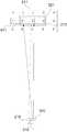
도 1은 본 발명에 따른 웨어러블 디스플레이장치의 실시예이다. 도 1(a)을 살펴보면, 웨어러블 디스플레이 장치는 착용수단(100), 디스플레이부(200)를 포함할 수 있다.1 is an embodiment of a wearable display device according to the present invention. 1 (a), the wearable display device may include a
착용수단(100)은 사용자의 머리에 착용이 가능하도록 구성된 장치이다. 도 1(a)과 같이, 착용수단(100)은 안경의 안경태의 형태로 구성될 수 있다. 따라서 사용자는 착용수단(100)을 사용자의 귀에 착용하여 머리에 고정하도록 한다. 착용수단(100)은 도 1(a)의 형태로 한정하지 않으며 머리에 착용 가능한 모든 형태로 구성될 수 있다. 일 예로, 착용수단(100)은 머리를 감싸는 형태의 밴드로도 구성될 수 있을 것이다.The wearing means 100 is a device configured to be worn on the user's head. As shown in Fig. 1 (a), the wearing means 100 may be configured in the form of an eyeglasses spectacle. Thus, the user wears the wearing means 100 on the user's ear and fixes it on the head. The
디스플레이부(200)는 사용자의 안구에 영상을 디스플레이하도록 구성된 장치이다. 도 1(a)와 같이, 디스플레이부(200)는 영상촬영부(210), 초점조절부(232), 초점조절지지부(234), 아날로그 변환부(240), 영상출력부(250), 제어부(260)를 포함할 수 있다.The
영상촬영부(210)는 카메라, 캠과 같이 영상촬영이 가능한 장치로 구성된다.The
초점조절부(232)는 출력되는 영상의 초점 또는 시축을 조절하기 위하여 영상출력부(250)를 상하 또는 좌우 방향으로 이동시키기 위한 장치이다. 초점조절지지부(234)는 초점조절부(232)를 디스플레이부(200)에 결합하기 위한 장치이다. 초점조절지지부(234)는 초점조절부(232)를 지지함으로써, 초점조절부(232)가 외부로 이탈 또는 이동되는 것을 방지한다. 또한, 초점조절지지부(234)는 영상출력부(250)를 감싸는 형태로 구성되어, 초점조절부(232)를 회전할 경우 영상출력부(250)가 함께 회전되는 것을 방지한다. 아날로그 변환부(240)는 영상출력부(250)를 통해 출력되는 영상을 아날로그영상으로 변환하여 출력하기 위한 장치이다. 영상출력부(250)는 영상촬영부(210)를 통해 촬영된 영상을 출력하기 위한 장치이다. 제어부(260)는 출력되는 영상의 시축을 이동시켜 출력되도록 제어하기 위한 장치이다. 영상의 시축조절 및 초점조절에 관한 내용은 후술한다.The
도 1(b)을 통해 디스플레이부(200)의 구조에 대해 좀 더 자세히 설명하도록 한다. 도 1(b)은 디스플레이부(200)의 일부를 확대한 도면이다. 도 1(b)을 살펴보면 초점조절부(232)가 디스플레이부(200)의 상단에 일정부분 돌출되어 있는 것을 확인할 수 있다. 이와 같이 초점조절부(232)가 일정부분 돌출됨에 따라 사용자는 초점조절부(232)의 측면을 잡고 회전시켜 영상의 초점을 조절한다. 초점조절연결부(233)은 초점조절부(232)의 하단에 채결되어 영상출력부(250)의 일측과 연결된다. 따라서 사용자가 초점조절부(232)를 특정방향으로 회전시키면 영상출력부(250)가 상하 방향으로 이동됨에 따라 영상의 초점이 조절된다. 일 예로 초점조절부(232)를 시계방향으로 회전시키면 영상출력부(250)가 상측방향으로 이동되며, 초점조절부(233)를 반시계방향으로 회전시키면 영상출력부(250)가 하측방향으로 이동된다.The structure of the
또한, 초점조절부(232)를 통해 영상의 시축을 조절하는 것이 가능하다. 도 1(b)와 같이, 초점조절부(232)는 초점조절지지부(234)의 상부측에 구비되며, 초점조절지지부(234)에는 천공홀(235)이 구비되어 있다. 사용자는 초점조절부(232)를 천공홀(235)내에서 좌우방향으로 이동할 수 있다. 영상출력부(250)는 초점연결부(233)를 통해 초점조절부(232)와 연결되어 있으며, 아날로그 변환부(240)는 영상출력부(250)와 고정된다. 따라서 초점조절부(232)를 초점조절지지대(234)에서 좌우로 이동시킴으로써, 사용자는 좌우 이동에 따른 시축이 변경된 영상을 제공받는 것이 가능하다. 도 1(a)을 살펴보면, 초점조절부(232)는 좌우에 각 구비된 것을 살펴볼 수 있다. 여기서 좌우에 각 구비된 초점조절부(232)는 동일하게 구성된다. 시축조절부(231)가 좌우에 각 구비됨에 따라 좌안과 우안에 출력되는 영상의 시축을 따로 조절하는 것이 가능하다. 시축을 조절하는 방법은 초점조절부(232)로 한정하지 않으며, 시축을 조절하기 위한 시축조절부(231)가 따로 구비되어 있다. 시축조절부(231)에 대한 기재는 후술한다.Further, it is possible to adjust the time axis of the image through the
영상출력부(250)의 상부는 초점조절연결부(233)와 연결되며, 하부는 영상을 출력하기 위한 영상패널이 구성된다. 영상패널은 LCD, LED, LCOS와 같이 영상출력이 가능한 장치이다. 도 1과 같이, 영상출력부(250)는 좌우 각 구비되며, 기능 및 구조는 동일하다.The upper part of the
아날로그 변환부(240)는 영상출력부(250)로부터 출력되는 영상을 수광하여, 사용자에게 출광가능한 형태로 구성된다. 따라서 아날로그 변환부(240)는 영상을 수광하기 위해 영상출력부(250)의 하단에 위치한다. 아날로그 변환부(240)는 영상의 수광 및 출광이 가능하도록 프리즘형태로 구성되는 것이 바람직하다. 도 1과 같이, 아날로그 변환부(240)는 좌우 각 구비되며, 기능 및 구조는 동일하다.
제어부(260)는 디스플레이부(260)내에 구성되며 도 1의 구조로 한정하지 않는다.The
도 2는 본 발명에 따른 디스플레이부의 구성도이다. 도 2를 살펴보면 디스플레이부(200)는 영상촬영부(210), 영상변환부(220), 조절부(230), 아날로그변환부(240), 영상출력부(250), 제어부(260)를 포함할 수 있다.2 is a configuration diagram of a display unit according to the present invention. 2, the
영상촬영부(210)는 영상을 촬영하기 위한 장치이다. 한편, 영상촬영부(210)를 통해 촬영된 영상은 기 설정된 해상도로 촬영된다. 예를 들어, 영상촬영부(210)를 통해 촬영되는 영상은 2,560 x 1,920 / 2,048 x 1,536 / 1,600 x 1,200 / 1,280 x 960 / 1,024 x 768 / 640 x 480 등의 해상도로 설정될 수 있다.The
영상변환부(220)는 기 설정된 해상도로 촬영된 영상을 기 설정된 해상도보다 저해상도인 특정 사물이나 생물의 인식이 가능한 시야해상도의 영상으로 변환한다. 예를 들어, 영상촬영부(210)를 통해 촬영된 영상이 1,600 x 1,200의 해상도일 경우, 일반적으로 사람은 1,600 x 1,200과 같이 고해상도를 보기 힘든 시력을 가지게 됨에 따라 1,600 x 1,200의 해상도를 촬영된 영상을 640 x 480과 같이 시야해상도를 낮추게 된다. 시야해상도에 대한 설명은 도 3을 통해 자세히 후술하도록 한다.The
조절부(230)는 영상촬영부(250)를 통해 촬영된 영상이 영상출력부(250)를 통하여 출력될 때, 출력되는 영상을 영상출력부(250)의 중심을 기준으로 일정 방향으로 가변시키기 위한 장치이다. 도 2와 같이, 조절부(230)는 시축조절부(231)와 초점조절부(232)를 포함할 수 있다.The
시축조절부(231)는 출력되는 영상을 영상출력부(250)의 중심을 기준으로 평면적으로 좌우 또는 상하 이동시키기 위한 장치이다. 시축조절부(231)에 따른 시축조절은 도 3내지 도 5를 통해 자세히 후술하도록 한다.The time
초점조절부(232)는 출력되는 영상의 초점 또는 시축을 조절하기 위하여 영상출력부(250)를 상하 또는 좌우 방향으로 이동시키기 위한 장치이다. 영상의 시축에 대한 기재는 앞서 설명한 바와 동일하며, 영상의 초점에 대한 설명은 도 6을 통해 자세히 후술하도록 한다.The
영상출력부(250)는 변환된 시야해상도의 영상을 출력가능한 영역내에서 기 설정된 일정범위만 출력하기 위한 장치이다.The
제어부(260)는 영상의 시축이동정보에 따라 영상출력부(250)를 제어하기 위한 장치이다. 예를 들어, 시축조절부(231)가 영상을 좌로 3 이동하라는 정보를 생성하면 제어부(260)는 영상출력부(250)에 '좌3'이라는 신호를 전송한다. 이를 통해 영상출력부(250)의 중심을 기준으로 좌로 3 이동된 영상이 영상출력부(250)에 출력된다.The
도 3은 본 발명에 따른 시력장애를 가진 사람과 웨어러블 디스플레이장치를 통해 촬영되는 시점을 설명하기 위한 실시예이다.FIG. 3 is a view for explaining a point of time when a person having a visual impairment according to the present invention is photographed through a wearable display device.
도 3을 살펴보면, 영상촬영부(210)를 통해 촬영되는 촬영영상(211)은 총 5 x 3의 영역으로 촬영된다. 촬영영상(211)의 해상도가 2000 x 1,200일 경우, 사용자는 2,000 x 1,200의 해상도로 촬영된 영상을 식별할 수 없는 문제가 발생 된다. 따라서 영상변환부(220)은 촬영영상(211)을 특정 사물이나 생물의 인식이 가능한 시야해상도의 변환영상(212)으로 변환한다. 도 3과 같이, 변환영상(212)은 촬영영상(211)을 중심으로 숫자 '2 3 4', 3 x 1의 변환영상(212)을 가진다. 따라서 변환영역(212)은 1,200 x 400의 해상도를 가지게 된다. 촬영영상(211)과 변환영상(212)의 영역과 해상도는 위의 예시로 한정되지 않으며, 거리, 렌즈 등에 의해 변경 될 수 있다.Referring to FIG. 3, the photographed
도 3을 살펴보면, 좌안(310)의 시점은 숫자 2에 맞춰있으며, 우안(320)의 시점은 숫자 3에 맞춰있다. 따라서 좌안시야(311)는 숫자 '1 2 3', 3 x 1의 영역이 되며, 우안시야(321)는 숫자 '2 3 4', 3 x 1의 영역이 된다. 일반적으로 좌안(310)과 우안(320)의 시점은 동일해야 하며, 도 3과 같이 좌안(310)과 우안(320)의 시점이 동일하지 않을 때는 사시라 일컫는다. 사용자가 정면을 응시하였을 경우 숫자 3에 시점이 맞춰지는 것이 정상이므로 사용자는 좌안(310)에 사시가 있다.Referring to FIG. 3, the viewpoint of the
이하 도 4를 통해 좌안시야(311)와 우안시야(312)가 다를 경우 발생하는 문제점에 대해 설명한다.4, a problem that occurs when the
도 4의 '촬영영상'을 살펴보면, 영상촬영부(210)를 통해 촬영된 촬영영상(211)은 도 3에서 설명한 바와 동일하다.Referring to the 'photographed image' of FIG. 4, the photographed
도 4의 '출력영상'을 살펴보면, 영상출력부(250)를 통해 출력되는 출력영상(262)은 도 3의 변환영상(212)을 출력한 영상이다. 한편, 출력가능영역(261)내에서 기 설정된 일정범위만 출력영상(262)이 출력되는 것을 확인할 수 있다. 따라서 출력영상(262)은 영상출력부(250)가 좌우 또는 상하 이동하게 되면, 시축이동에 따라 출력영상(262)과 미출력영상(263)의 영역은 변경된다. 한편, 출력영상(262)과 미출력영상(263)의 영역범위는 사용자에 의해 임의 설정되는 것이 가능하다.Referring to the 'output image' of FIG. 4, the
도 4의 '정상시력자가 볼 경우'를 살펴보면, 정상시력자는 '2 3 4'의 출력영상(262)을 동일하게 보게 된다.Referring to FIG. 4, the 'normal viewers' view, the normal viewers see the
반면, 도 4의 '비정상시력자가 볼 경우(좌안 외사시)'를 살펴보면, 좌안시야(311)가 '1 2 3'으로 시야가 좌측으로 일부 치우친 것을 확인할 수 있다. 따라서 좌안 외사시를 가진 사용자는 '2 3 4'로 출력되는 영상 중 '2 3'만을 보게 된다. '1'의 영상은 출력되지 않기 때문에, 좌안(310)으로는 '미출력영상 2 3', 우안(320)으로는 '2 3 4'의 영역을 보게 된다. 따라서 양안으로 영상출력부(250)를 봤을 시 복시현상이 나타나게 된다. 여기서 복시현상은 좌안과 우안의 초점이 동일하지 못함에 따라 발생 되는 현상이다. 도 4의 경우는 좌안의 미출력영상과 우안의 2의 초점이 동일하고, 좌안의 2와 우안의 3의 초점이 동일하며, 좌안의 3과 우안의 4의 초점이 동일함에 따라, 영상이 흔들려 보이는 증상이 발생한다.On the other hand, if the 'abnormal vision' (left eye exotropia) of FIG. 4 is examined, it can be confirmed that the
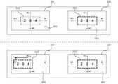
이하 도 5를 통해 복시현상을 해결하기 위한 영상의 시축조절에 대하여 설명한다. 도 5는 본 발명에 따른 웨어러블 디스플레이장치의 시축조절을 설명하기 위한 실시예이다. 먼저 도 5를 살펴보면, 가로축으로 BO(Base Out), BI(Base In)가 형성되며, 세로축으로 BU(Base Up), BD(Base Down)가 형성되어 있는 것을 확인할 수 있다. BO는 시점을 중심으로 외축을 의미하며, BI는 시점을 중심으로 내축을 의미한다. 따라서 시점이 BO에 치우치면 외사시, BI에 치우치면 내사시이다. BU는 시점을 중심으로 상축을 의미하며, BI는 시점을 중심으로 하축을 의미한다. 따라서 시점이 BU에 치우치면 상사시, BD에 치우치면 하사시이다.5, a description will now be made of the adjustment of the time axis of an image for solving the phenomenon of a skipping phenomenon. FIG. 5 is a view for explaining a time axis adjustment of a wearable display device according to the present invention. 5, it can be seen that BO (Base Out) and BI (Base In) are formed along the horizontal axis and BU (Base Up) and BD (Base Down) are formed along the vertical axis. BO is the outer axis around the viewpoint, and BI is the inner axis around the viewpoint. Therefore, if the viewpoint is shifted to the BO, it is exotropic if it is exotropia, bias to BI. BU stands for the phase axis around the viewpoint, and BI stands for the lower axis around the viewpoint. Therefore, if the timing shifts to BU, it will be inferior if shifted to BD.
도 5의 상측도면은 일반적으로 디스플레이되는 출력영상(262)이다. 도 5의 상측도면을 살펴보면, 출력가능영역(261)내에서 '2 3 4'의 출력영상(262)이 BU, BD, BO, BI 중 어느 한곳에 치우치지 않고 디스플레이된 것을 확인할 수 있다.5 is an
도 5의 하측도면은 좌안에 내사시가 있는 경우 디스플레이되는 출력영상(262)이다. 도 6의 하측도면을 살펴보면, 좌측에 출력되는 '2 3 4'의 출력영상(262)이 출력가능영역(261)내에서 BO방향으로 일정부분 이동되어 디스플레이된 것을 확인할 수 있다.5 is an
출력영상(262)의 시축을 이동시키기 위해서는, 먼저 시축조절부(231)는 출력력되는 영상을 영상출력부(250)의 중심을 기준으로 평면적으로 좌우 또는 상하 이동시키기 위한 신호를 생성한다. 제어부(260)는 시축조절부(231)로부터 이동신호를 수신받아, 출력영상(262)이 이동신호에 따라 디스플레이되도록 영상출력부(250)를 제어한다. 일 예로, 출력가능영역(261)내에서 출력된 출력영상(262)이 BO:0, BI:0, BU:0, BD:0에 위치할 경우, BO:0, BI:0, BU:0, BD:0를 중심(영상출력부의 중심)으로 기 설정된 일정범위만 영상이 출력되며, 그 외의 영역은 미출력영상(263)이 된다. 시축조절부(231)에 BO로 3의 이동신호가 생성되었다면 제어부(260)은 출력영상(262)이 BO:3, BI:0, BU:0, BD:-3를 중심으로 출력되도록 영상출력부(250)를 제어한다. 출력영상(262)을 좌안(310)의 시점으로 시축이동함에 따라 사용자는 복시현상없이 출력영상(262)을 볼 수 있다. 여기서 단위는 mm, um 등 사용자에 의해 설정된 단위이다.In order to move the time axis of the
도 6은 본 발명에 따른 웨어러블 디스플레이장치의 초점조절을 설명하기 위한 실시예이다. 도 6의 좌측도면은 아날로그 변환부(240)가 디스플레이부(200)에 포함되었을 경우이며, 우측도면은 아날로그 변환부(240)가 디스플레이부(200)에 미포함되었을 경우이다.FIG. 6 is a view for explaining focus control of a wearable display device according to the present invention. 6 shows a case where the
도 6의 좌측도면을 살펴보면, 아날로그 변환부(240)는 영상출력부(250)로부터 출력되는 영상을 수광하기 위한 수광부(241)와 영상을 외부로 출광하기 위한 출광부(242)를 포함할 수 있다.6, the
수광부(241)는 영상출력부(250)로부터 출력되는 영상을 수광하기 위하여 영상출력부(250)와 평행하게 위치한다. 출광부(242)는 수광부(241)를 통해 수광된 영상이 사용자의 안구에 출광되도록 위치하며, 출광부(242)는 수광부(241)에서 일정각도 기울어져 사선으로 형성된다.The
도 6의 좌측도면을 살펴보면, 초점조절부(232)가 디스플레이부(200)의 상단에 위치하며, 초점조절부(232)와 영상출력부(250)는 초점조절연결부(233)에 의해 연결된 것을 확인할 수 있다. 따라서 영상출력부(250)의 상하이동에 따라 수광부(241)로 출력되는 영상의 거리가 변경됨에 따라 출광부(242)에서 출광되는 영상의 초점이 조절된다. 영상출력부(250)를 통해 출력되는 영상은 디지털영상이다. 출력되는 디지털영상은 아날로그변환부(240)에 수광되어 빛으로 출광됨으로써, 디지털영상은 아날로그영상으로 변환된다. 이를 통해, 사용자는 눈의 피로를 감소시킬 수 있는 효과가 있다. 한편, 아날로그변환부(240)는 디스플레이부(200)에 고정된 구조이기 때문에 영상출력부(250)가 상하 또는 좌우방향으로 이동되더라도 사용자의 안구(300)에서 받아들이는 영상의 해상도는 변경되지 않는다.6, the
도 6의 우측도면은 아날로그 변환부(240)가 미포함되었을 경우의 웨어러블 디스플레이장치의 실시예이다. 도 6의 우측도면을 살펴보면, 초점조절부(232)가 디스플레이부(200)의 외측에 위치한다. 내측면에는 영상의 출력이 가능하도록 영상출력부(250)가 위치한다. 초점조절부(232)와 영상출력부(250)는 초점조절연결부(233)에 의해 연결된 것을 확인할 수 있다. 따라서 초점조절부(232)를 시계방향으로 회전시 영상출력부(250)는 전방으로 이동되며, 반시계방향으로 회전시 후방으로 이동된다. 영상출력부(250)의 전후이동에 따라 영상출력부(250)에서 출력되는 영상이 변경되어 영상의 초점이 조절된다. 도 6의 우측도면은 아날로그변환부(240)가 미포함됨에 따라 영상출력부(250)로부터 출력되는 디지털영상이 사용자의 안구(300)에 근접하여 출력된다. 따라서 영상출력부(250)가 전후방향으로 이동됨으로써, 출력영상이 눈과 일정한 거리에 디스플레이되는 구조이다.6 is an embodiment of a wearable display device when the
초점조절부(232)와 영상출력부(250)가 연결되는 구조는 도 6과 같이 나사선으로 한정하지 않는다. 기어를 사용하는 다양한 구조(랙 기어, 랙 피니언, 베밸 기어 등)로 변경되어 설계될 수 있다.
The structure in which the
이상에서 설명한 본 발명은, 본 발명이 속하는 기술분야에서 통상의 지식을 가진 자에게 있어 본 발명의 기술적 사상을 벗어나지 않는 범위 내에서 여러 가지 치환, 변형 및 변경이 가능하므로 전술한 실시 예 및 첨부된 도면에 의해 한정되는 것이 아니다. 일 예로, 도 1의 웨어러블 디바이스장치의 형태는 변경될 수 있으며, 도 6의 아날로그변환부도 포함되거나 미포함될 수 있는 구조이다.
It will be apparent to those skilled in the art that various modifications and variations can be made in the present invention without departing from the spirit or scope of the invention. The present invention is not limited to the drawings. For example, the form of the wearable device device of Fig. 1 may be changed, and the structure may be included with or without the analog conversion portion of Fig.
100 : 착용수단200 : 디스플레이부
210 : 영상촬영부211 : 촬영영상
212 : 변환영상220 : 영상변환부
230 : 조절부231 : 시축조절부
232 : 초점조절부233 : 초점조절연결부
234 : 초점조절지지부345 : 장공홀
240 : 아날로그변환부241 : 수광부
242 : 출광부250 : 영상출력부
260 : 제어부261 : 출력가능영역
262 : 출력영역263 : 미출력영역
300 : 안구310 : 좌안
320 : 우안100: Wearing means 200:
210: image capturing unit 211: captured image
212: converted image 220: image conversion unit
230: adjusting part 231:
232: Focus adjustment part 233: Focus adjustment connection part
234: Focus adjustment support part 345: Long hole
240: analog conversion section 241:
242: Light exiting section 250:
260: control unit 261:
262: output area 263: no output area
300: eyeball 310: left eye
320: Right eye
Claims (7)
Translated fromKorean상기 디스플레이부는,
영상촬영부;
상기 영상촬영부를 통해 촬영된 영상 중 기 설정된 특정영역을 변환영상으로 변환하는 영상변환부;
상기 변환영상이 출력되는 출력영역 및 상기 출력영역이 제외된 미출력영역을 포함하는 출력가능영역내에서 상기 변환영상을 출력하는 영상출력부;
상기 비정상시력자에게 제공되며, 정상시력자의 시축을 기준으로 출력되는 상기 출력영역을 상기 비정상시력자에 의하여 평면적으로 좌우 또는 상하로 이동시키기 위한 신호를 생성하는 시축조절부, 및 상기 변환영상의 해상도 변경을 위한 초점을 조절시키기 위하여 상기 영상출력부를 이동시키기 위한 초점조절부를 포함하는 조절부; 및
상기 시축조절부에 생성된 신호에 따라 상기 출력영역이 상기 출력가능영역내에서 이동되도록 상기 영상출력부를 제어하는 제어부;를 포함하는 것을 특징으로 하는 웨어러블 디스플레이 장치.A display unit for displaying an image while maintaining a predetermined distance from the eyes of the unaided eye; And wearing means for wearing the display portion on the user's face,
The display unit includes:
Image capturing unit;
An image converting unit for converting a preset specific area of the image photographed through the image photographing unit into a converted image;
An image output unit for outputting the converted image in an outputable area including an output area in which the converted image is output and a non-output area in which the output area is excluded;
A time axis adjusting unit for generating a signal for the abnormal viewer to move the output region based on the time axis of the normal vision player by the abnormal viewer in a horizontal direction or in a vertical direction, A focusing unit for moving the image output unit to adjust a focus for the image; And
And a control unit for controlling the image output unit so that the output area is moved in the output-enabled area according to a signal generated in the time axis adjustment unit.
상기 초점조절부는 초점조절지지대의 상부측에 구비되며, 상기 초점조절지지대에서 좌우로 이동함에 따라, 상기 초점조절부에 결합된 상기 영상출력부가 좌우로 이동되어 시축이 조절되는 기능을 포함하는 것을 특징으로 하는 웨어러블 디스플레이장치.The method according to claim 1,
The focus adjustment unit is provided on the upper side of the focus adjustment support and includes a function of moving the image output unit coupled to the focus adjustment unit as the focus adjustment unit is moved from side to side to adjust the time axis. To the wearable display device.
상기 영상출력부에서 출력되는 영상을 수광하기 위한 수광부; 및 상기 수광된 영상을 아날로그영상으로 변환하여 외부로 출광하기 위한 출광부를 포함하는 아날로그변환부를 더 포함하는 것을 특징으로 하는 웨어러블 디스플레이장치.The method of claim 3,
A light receiving unit for receiving an image output from the image output unit; And an analog conversion unit including an emitting unit for converting the received image into an analog image and outputting the analog image to the outside.
Priority Applications (2)
| Application Number | Priority Date | Filing Date | Title |
|---|---|---|---|
| KR1020140134857AKR101650706B1 (en) | 2014-10-07 | 2014-10-07 | Device for wearable display |
| PCT/KR2014/010769WO2016056699A1 (en) | 2014-10-07 | 2014-11-11 | Wearable display device |
Applications Claiming Priority (1)
| Application Number | Priority Date | Filing Date | Title |
|---|---|---|---|
| KR1020140134857AKR101650706B1 (en) | 2014-10-07 | 2014-10-07 | Device for wearable display |
Publications (2)
| Publication Number | Publication Date |
|---|---|
| KR20160041265A KR20160041265A (en) | 2016-04-18 |
| KR101650706B1true KR101650706B1 (en) | 2016-09-05 |
Family
ID=55653297
Family Applications (1)
| Application Number | Title | Priority Date | Filing Date |
|---|---|---|---|
| KR1020140134857AExpired - Fee RelatedKR101650706B1 (en) | 2014-10-07 | 2014-10-07 | Device for wearable display |
Country Status (2)
| Country | Link |
|---|---|
| KR (1) | KR101650706B1 (en) |
| WO (1) | WO2016056699A1 (en) |
Cited By (1)
| Publication number | Priority date | Publication date | Assignee | Title |
|---|---|---|---|---|
| US12235523B2 (en) | 2020-07-07 | 2025-02-25 | Samsung Electronics Co., Ltd. | Device and method for correcting user's vision and performing calibration |
Families Citing this family (7)
| Publication number | Priority date | Publication date | Assignee | Title |
|---|---|---|---|---|
| KR101968399B1 (en)* | 2017-03-21 | 2019-04-12 | 엔에이치엔 주식회사 | Method and system forcontrolling focusing length to enhance vision |
| KR102009624B1 (en)* | 2019-04-04 | 2019-08-12 | 엔에이치엔 주식회사 | Method and system forcontrolling focusing length to enhance vision |
| KR102120112B1 (en)* | 2020-02-11 | 2020-06-09 | 가천대학교 산학협력단 | System, Method and Computer-readable Medium for Rehabilitation training with Virtual Reality for Patients with Exotropia Based on Artificial Intelligence |
| KR20220128726A (en) | 2021-03-15 | 2022-09-22 | 삼성전자주식회사 | Head-worn display device, operating method in the device, and storage medium |
| KR102633491B1 (en)* | 2021-07-06 | 2024-02-06 | 주식회사 피앤씨솔루션 | Augmented reality glasses device with adjustable virtual image distance |
| KR102823347B1 (en)* | 2022-08-23 | 2025-06-20 | 주식회사 피앤씨솔루션 | Ar glasses apparatus with automatic adjustable virtual image distance |
| CN120113232A (en)* | 2022-11-07 | 2025-06-06 | 三星电子株式会社 | Wearable electronic device including camera and method of operating the same |
Citations (1)
| Publication number | Priority date | Publication date | Assignee | Title |
|---|---|---|---|---|
| US20060250322A1 (en) | 2005-05-09 | 2006-11-09 | Optics 1, Inc. | Dynamic vergence and focus control for head-mounted displays |
Family Cites Families (7)
| Publication number | Priority date | Publication date | Assignee | Title |
|---|---|---|---|---|
| JP2004029768A (en)* | 1993-08-20 | 2004-01-29 | Seiko Epson Corp | Head mounted image display |
| JPH0756517A (en)* | 1993-08-20 | 1995-03-03 | Matsushita Electric Ind Co Ltd | Eyeglass type image display device |
| JP3302130B2 (en)* | 1993-11-02 | 2002-07-15 | オリンパス光学工業株式会社 | Head mounted video display |
| JP5237268B2 (en)* | 2007-11-21 | 2013-07-17 | パナソニック株式会社 | Display device |
| US8665177B2 (en)* | 2010-02-05 | 2014-03-04 | Kopin Corporation | Touch sensor for controlling eyewear |
| WO2011106797A1 (en)* | 2010-02-28 | 2011-09-01 | Osterhout Group, Inc. | Projection triggering through an external marker in an augmented reality eyepiece |
| KR101419007B1 (en) | 2013-01-08 | 2014-07-11 | 주식회사 고글텍 | Head mounted stereoscopy device for a smart phone |
- 2014
- 2014-10-07KRKR1020140134857Apatent/KR101650706B1/ennot_activeExpired - Fee Related
- 2014-11-11WOPCT/KR2014/010769patent/WO2016056699A1/enactiveApplication Filing
Patent Citations (1)
| Publication number | Priority date | Publication date | Assignee | Title |
|---|---|---|---|---|
| US20060250322A1 (en) | 2005-05-09 | 2006-11-09 | Optics 1, Inc. | Dynamic vergence and focus control for head-mounted displays |
Cited By (1)
| Publication number | Priority date | Publication date | Assignee | Title |
|---|---|---|---|---|
| US12235523B2 (en) | 2020-07-07 | 2025-02-25 | Samsung Electronics Co., Ltd. | Device and method for correcting user's vision and performing calibration |
Also Published As
| Publication number | Publication date |
|---|---|
| WO2016056699A1 (en) | 2016-04-14 |
| KR20160041265A (en) | 2016-04-18 |
Similar Documents
| Publication | Publication Date | Title |
|---|---|---|
| KR101650706B1 (en) | Device for wearable display | |
| US10455224B2 (en) | Digital inter-pupillary distance adjustment | |
| US10445573B2 (en) | Gaze detection device | |
| CN204101815U (en) | A kind of virtual glasses repaid based on optics and pattern distortion complementation | |
| JP6658529B2 (en) | Display device, display device driving method, and electronic device | |
| US11126014B2 (en) | Eyewear, eyewear systems and associated methods for enhancing vision | |
| US20200142480A1 (en) | Immersive displays | |
| US20200275071A1 (en) | Electronic visual headset | |
| CN104090371B (en) | A kind of 3D glasses and 3D display systems | |
| CN107636514A (en) | Head-mounted display device and visual aid method using same | |
| US20090059364A1 (en) | Systems and methods for electronic and virtual ocular devices | |
| CN104407437A (en) | Zoom head-worn equipment | |
| US20160363776A1 (en) | Reflective Mobile Phone Cinema Lens | |
| JP7118650B2 (en) | Display device | |
| JP2018513656A (en) | Eyeglass structure for image enhancement | |
| JP2015228543A (en) | Electronic device and display processing method | |
| JP6576639B2 (en) | Electronic glasses and control method of electronic glasses | |
| CN107229122A (en) | Head-mounted display device | |
| JP2017191546A (en) | Medical use head-mounted display, program of medical use head-mounted display, and control method of medical use head-mounted display | |
| EP3200003A1 (en) | Glasses-free 3d display device | |
| CN113454989A (en) | Head-mounted display device | |
| CN105738981A (en) | Lens and camera lens comprising the same and head-worn display | |
| CN105589198A (en) | Head-mounted display | |
| JP2018152748A (en) | Imaging/display device of stereoscopic image and head mount device | |
| TWI676048B (en) | Near-eye display structure |
Legal Events
| Date | Code | Title | Description |
|---|---|---|---|
| A201 | Request for examination | ||
| PA0109 | Patent application | St.27 status event code:A-0-1-A10-A12-nap-PA0109 | |
| PA0201 | Request for examination | St.27 status event code:A-1-2-D10-D11-exm-PA0201 | |
| E902 | Notification of reason for refusal | ||
| PE0902 | Notice of grounds for rejection | St.27 status event code:A-1-2-D10-D21-exm-PE0902 | |
| T11-X000 | Administrative time limit extension requested | St.27 status event code:U-3-3-T10-T11-oth-X000 | |
| E13-X000 | Pre-grant limitation requested | St.27 status event code:A-2-3-E10-E13-lim-X000 | |
| P11-X000 | Amendment of application requested | St.27 status event code:A-2-2-P10-P11-nap-X000 | |
| P13-X000 | Application amended | St.27 status event code:A-2-2-P10-P13-nap-X000 | |
| E90F | Notification of reason for final refusal | ||
| PE0902 | Notice of grounds for rejection | St.27 status event code:A-1-2-D10-D21-exm-PE0902 | |
| PG1501 | Laying open of application | St.27 status event code:A-1-1-Q10-Q12-nap-PG1501 | |
| E13-X000 | Pre-grant limitation requested | St.27 status event code:A-2-3-E10-E13-lim-X000 | |
| P11-X000 | Amendment of application requested | St.27 status event code:A-2-2-P10-P11-nap-X000 | |
| P13-X000 | Application amended | St.27 status event code:A-2-2-P10-P13-nap-X000 | |
| E701 | Decision to grant or registration of patent right | ||
| PE0701 | Decision of registration | St.27 status event code:A-1-2-D10-D22-exm-PE0701 | |
| GRNT | Written decision to grant | ||
| PR0701 | Registration of establishment | St.27 status event code:A-2-4-F10-F11-exm-PR0701 | |
| PR1002 | Payment of registration fee | St.27 status event code:A-2-2-U10-U11-oth-PR1002 Fee payment year number:1 | |
| PG1601 | Publication of registration | St.27 status event code:A-4-4-Q10-Q13-nap-PG1601 | |
| PN2301 | Change of applicant | St.27 status event code:A-5-5-R10-R11-asn-PN2301 | |
| PN2301 | Change of applicant | St.27 status event code:A-5-5-R10-R14-asn-PN2301 | |
| P14-X000 | Amendment of ip right document requested | St.27 status event code:A-5-5-P10-P14-nap-X000 | |
| R18-X000 | Changes to party contact information recorded | St.27 status event code:A-5-5-R10-R18-oth-X000 | |
| FPAY | Annual fee payment | Payment date:20190812 Year of fee payment:4 | |
| PR1001 | Payment of annual fee | St.27 status event code:A-4-4-U10-U11-oth-PR1001 Fee payment year number:4 | |
| P22-X000 | Classification modified | St.27 status event code:A-4-4-P10-P22-nap-X000 | |
| P22-X000 | Classification modified | St.27 status event code:A-4-4-P10-P22-nap-X000 | |
| PC1903 | Unpaid annual fee | St.27 status event code:A-4-4-U10-U13-oth-PC1903 Not in force date:20200819 Payment event data comment text:Termination Category : DEFAULT_OF_REGISTRATION_FEE | |
| PC1903 | Unpaid annual fee | St.27 status event code:N-4-6-H10-H13-oth-PC1903 Ip right cessation event data comment text:Termination Category : DEFAULT_OF_REGISTRATION_FEE Not in force date:20200819 |