KR101649718B1 - An Automatic Clip Applier for a Surgical Operation - Google Patents
An Automatic Clip Applier for a Surgical OperationDownload PDFInfo
- Publication number
- KR101649718B1 KR101649718B1KR1020140149830AKR20140149830AKR101649718B1KR 101649718 B1KR101649718 B1KR 101649718B1KR 1020140149830 AKR1020140149830 AKR 1020140149830AKR 20140149830 AKR20140149830 AKR 20140149830AKR 101649718 B1KR101649718 B1KR 101649718B1
- Authority
- KR
- South Korea
- Prior art keywords
- clip
- guide tube
- unit
- case
- clips
- Prior art date
- Legal status (The legal status is an assumption and is not a legal conclusion. Google has not performed a legal analysis and makes no representation as to the accuracy of the status listed.)
- Expired - Fee Related
Links
Images


Classifications
- A—HUMAN NECESSITIES
- A61—MEDICAL OR VETERINARY SCIENCE; HYGIENE
- A61B—DIAGNOSIS; SURGERY; IDENTIFICATION
- A61B17/00—Surgical instruments, devices or methods
- A61B17/10—Surgical instruments, devices or methods for applying or removing wound clamps, e.g. containing only one clamp or staple; Wound clamp magazines
- A—HUMAN NECESSITIES
- A61—MEDICAL OR VETERINARY SCIENCE; HYGIENE
- A61B—DIAGNOSIS; SURGERY; IDENTIFICATION
- A61B17/00—Surgical instruments, devices or methods
- A61B17/068—Surgical staplers, e.g. containing multiple staples or clamps
- A—HUMAN NECESSITIES
- A61—MEDICAL OR VETERINARY SCIENCE; HYGIENE
- A61B—DIAGNOSIS; SURGERY; IDENTIFICATION
- A61B17/00—Surgical instruments, devices or methods
- A61B17/08—Wound clamps or clips, i.e. not or only partly penetrating the tissue ; Devices for bringing together the edges of a wound
- A61B17/083—Clips, e.g. resilient
- A—HUMAN NECESSITIES
- A61—MEDICAL OR VETERINARY SCIENCE; HYGIENE
- A61B—DIAGNOSIS; SURGERY; IDENTIFICATION
- A61B17/00—Surgical instruments, devices or methods
- A61B17/12—Surgical instruments, devices or methods for ligaturing or otherwise compressing tubular parts of the body, e.g. blood vessels or umbilical cord
- A61B17/122—Clamps or clips, e.g. for the umbilical cord
- A61B17/1222—Packages or dispensers therefor
- A—HUMAN NECESSITIES
- A61—MEDICAL OR VETERINARY SCIENCE; HYGIENE
- A61B—DIAGNOSIS; SURGERY; IDENTIFICATION
- A61B17/00—Surgical instruments, devices or methods
- A61B17/12—Surgical instruments, devices or methods for ligaturing or otherwise compressing tubular parts of the body, e.g. blood vessels or umbilical cord
- A61B17/128—Surgical instruments, devices or methods for ligaturing or otherwise compressing tubular parts of the body, e.g. blood vessels or umbilical cord for applying or removing clamps or clips
- A61B17/1285—Surgical instruments, devices or methods for ligaturing or otherwise compressing tubular parts of the body, e.g. blood vessels or umbilical cord for applying or removing clamps or clips for minimally invasive surgery
Landscapes
- Health & Medical Sciences (AREA)
- Surgery (AREA)
- Life Sciences & Earth Sciences (AREA)
- Heart & Thoracic Surgery (AREA)
- Nuclear Medicine, Radiotherapy & Molecular Imaging (AREA)
- Engineering & Computer Science (AREA)
- Biomedical Technology (AREA)
- Medical Informatics (AREA)
- Molecular Biology (AREA)
- Animal Behavior & Ethology (AREA)
- General Health & Medical Sciences (AREA)
- Public Health (AREA)
- Veterinary Medicine (AREA)
- Vascular Medicine (AREA)
- Reproductive Health (AREA)
- Surgical Instruments (AREA)
Abstract
Translated fromKorean
Description
Translated fromKorean본 발명은 의료용 클립 애플라이어에 관한 것이고, 구체적으로 수술 과정에서 클립의 이탈이 방지될 수 있도록 하는 의료용 오토메틱 클립 애플라이어에 관한 것이다.The present invention relates to a medical clip applier, and more particularly, to a medical automatic clip applier that allows a clip to be prevented from being released during a surgical procedure.
인체 내부의 수술 과정에서 혈관 또는 맹장과 같은 길이 방향으로 연장되는 인체 기관의 파지 또는 절제를 위하여 의료용 클립이 사용될 수 있다. 예를 들어 충수돌기 절제 수술 과정에서 맹장 또는 혈관을 파지하거나, 결찰하거나 또는 지혈하기 위하여 클립이 사용된다. 이와 같은 의료용 클립은 예를 들어 탄성을 가진 금속 또는 폴리머 소재로 만들어질 수 있다. 수술 과정에서 혈관 또는 맹장의 일부와 같은 신체 일부의 결찰을 위하여 다수 개의 클립이 애플라이어에 차례로 배치되어 사용될 수 있다. 그리고 클립의 사용 전 애플라이어는 멸균 또는 살균 과정을 거치게 되거나 장시간 동안 방치된 상태로 될 수 있다. 애플라이어가 이와 같은 상태가 되는 경우 내부에 배치된 클립의 탄성과 같은 물리적 특성이 변할 수 있고 이로 인하여 애플라이어의 끝 부분에 배치된 조 유닛으로 전달되어 사용되는 과정에서 클립이 이탈될 수 있다. 또한 다수 개의 클립이 연속적으로 애플라이어의 공급 튜브에 배치되어 있으므로 뒤쪽에 배치된 클립은 시간의 경과와 함께 물리적 특성이 변할 수 있다. 그러므로 이와 같이 사용 전 클립의 물리적 특성이 그대로 유지되고 안정적으로 수술 과정에서 사용될 수 있도록 하는 클립 애플라이어가 요구된다.Medical clips may be used for gripping or resecting a human organ extending in the longitudinal direction, such as a blood vessel or cecum, during an intra-human surgical procedure. For example, clips are used to grasp, ligature, or bleed the appendix or blood vessels during an appendectomy procedure. Such a medical clip may be made of, for example, a resilient metal or polymer material. A number of clips may be sequentially placed on the apple lyre for ligation of a part of the body, such as a part of the blood vessels or cecum during the surgical procedure. And before using the clip, the Apple lyre may be sterilized or sterilized or left unattended for extended periods of time. If the Apple lyer is in this state, the physical properties, such as the elasticity of the clip placed inside it, can change, which can lead to the jaw unit placed at the end of the Apple lyre and cause the clip to separate during use. Also, since a plurality of clips are successively placed in the supply tube of the Apple Liaer, the clips placed on the rear side may change their physical properties over time. Thus, there is a need for a clip applier that maintains the physical characteristics of the clip before use and can be used stably in the surgical procedure.
미국 특허등록번호 7,316,696은 유연성 힌지 영역에 의하여 끝 부분에서 결합되고 곡면 형상의 마주보는 내부 표면 사이에 혈관을 파지하기 위하여 열린 위치로부터 닫힌 위치로 이동 가능한 제1 및 제2 곡선 다리를 가지는 고분자 소재의 외과 클립에 대하여 개시한다.U.S. Patent No. 7,316,696 discloses a polymeric material having first and second curved legs that are joined at their ends by a flexible hinge region and are movable from an open position to a closed position for gripping blood vessels between opposed inner surfaces of a curved shape A surgical clip is disclosed.
미국 특허등록번호 7,052,504는 구동 기기, 한 쌍의 마주보는 조(jaws) 및 그들 사이에 배치된 연장 어셈블리로 이루어진 외과용 클립 애플라이어에 대하여 개시한다. 상기 선행기술은 연장 어셈블리에 배치된 클립 구동 디바이스가 조에 결합되도록 연장 어셈블리를 통하여 연속적으로 클립을 이동시키기 위하여 구동 기기에 의하여 작동되고, 클립 제어 부품이 연장 어셈블리의 끝 부분에 배치되고, 클립 제어 부품은 제1, 2 및 3 클립 제어 표면을 포함하고, 제1 클립 제어 표면은 클립의 제1 끝 부분에 접촉하여 클립이 제1 끝 부분 주위로 회전하도록 만들고, 제2 및 제3 제어 표명은 조와 결합되도록 클립이 이동되기 전 클립의 끝 부분을 수용하는 자동 공급 외과용 클립 애플라이어에 대하여 개시한다.U.S. Patent No. 7,052,504 discloses a surgical clip applier comprising a drive device, a pair of opposing jaws, and an extension assembly disposed therebetween. The prior art teaches that the clip control component is actuated by the drive to continuously move the clip through the extension assembly so that the clip drive device disposed in the extension assembly is coupled to the jaw and the clip control component is disposed at the end of the extension assembly, The first clip control surface contacting the first end portion of the clip to cause the clip to rotate about the first end portion and the second and third control manifesting surfaces to engage the first, Discloses an automated supply surgeon clip applier that receives an end portion of a clip before the clip is moved to engage.
미국 특허공개번호 US 2014/0052157A1은 핸들 부분; 핸들 부분으로부터 연장하는 몸체; 몸체 내부에 배치된 다수 개의 외과용 클립; 및 몸체의 끝 부분에 인접하도록 설치된 조 유닛으로 이루어진 신체 조직을 위한 외과용 클립의 적용을 위한 장치에 대하여 개시한다.United States Patent Publication No. US 2014 / 0052157A1 discloses a handle portion; A body extending from the handle portion; A plurality of surgical clips disposed within the body; And a coarse unit arranged adjacent to an end of the body, for the application of a surgical clip for body tissues.
상기 선행기술에서 개시된 애플라이어는 클립이 유도 튜브에 배치된 상태에서 멸균 또는 살균을 위하여 고온 상태로 놓이게 되고 이로 인하여 클립의 탄성 또는 물리적 특성이 변할 수 있다는 문제점을 가진다. 또한 상기 선행기술에서 개시된 애플라이어는 미리 정해진 각도로 유지되는 클립이 차례대로 수술 과정에서 공급되도록 하는 것에 의하여 클립의 탄성이 유지되기 어렵게 하면서 이와 동시에 애플라이어의 보관 및 취급이 어렵다는 문제점을 가진다.The Apple lira disclosed in the prior art has a problem that the clip is placed in a high temperature state for sterilization or sterilization in a state where it is disposed in the induction tube and thereby the elasticity or physical characteristics of the clip may be changed. In addition, the appliers disclosed in the prior art have a problem in that it is difficult to maintain the elasticity of the clip by keeping the clip maintained at a predetermined angle in order during the operation, and at the same time, it is difficult to store and handle the apple.
본 발명은 선행기술의 문제점을 해결하기 위한 것으로 아래와 같은 목적을 가진다.The present invention has been made to solve the problems of the prior art and has the following purpose.
본 발명의 목적은 예비적으로 클립을 보관하면서 사용 전 클립을 정해진 위치로 이동되도록 하는 예비 유닛을 가진 의료용 오토메틱 클립 애플라이어를 제공하는 것이다.It is an object of the present invention to provide a medical automatic clip applier having a spare unit for preliminarily storing a clip and moving the clip before use to a predetermined position.
본 발명의 적절한 실시 형태에 따르면, 의료용 오토메틱 클립 애플라이어는 내부에 클립의 수용이 가능한 케이스; 케이스에 수용된 클립의 이동을 위한 이동 유닛; 케이스로부터 이동된 클립이 배치되는 유도 튜브; 및 유도 튜브에 배치된 클립이 차례대로 전달되는 조 유닛을 포함하고, 상기 케이스에 수용된 클립이 이동 유닛에 의하여 유도 튜브로 모두 이동되고, 유도 튜브로부터 조 유닛으로 클립이 차례대로 전달된다.According to a preferred embodiment of the present invention, a medical automatic clip applier comprises a case capable of receiving a clip therein; A moving unit for moving the clip received in the case; A guide tube in which a clip moved from the case is disposed; And the clips arranged in the guide tube are sequentially transmitted. The clips received in the case are all moved to the guide tube by the moving unit, and the clips are sequentially transmitted from the guide tube to the jaw unit.
본 발명의 다른 적절한 실시 형태에 따르면, 이동 유닛은 상기 클립이 차례대로 배치되는 가이드 채널 및 가이드 채널에 결합되어 상기 클립을 이동시키기 위한 푸시 유닛을 포함한다.According to another preferred embodiment of the present invention, the mobile unit comprises a guide channel in which the clips are arranged in order and a pushing unit coupled to the guide channel for moving the clip.
본 발명의 또 다른 적절한 실시 형태에 따르면, 상기 가이드 채널의 폭은 유도 튜브의 폭에 비하여 크다.According to another preferred embodiment of the present invention, the width of the guide channel is larger than the width of the guide tube.
본 발명의 또 다른 적절한 실시 형태에 따르면, 상기 푸시 유닛은 케이스의 덮개에 형성된 이동 가이드를 따라 이동 가능하도록 배치된다.According to another preferred embodiment of the present invention, the push unit is arranged to be movable along a movement guide formed on a cover of the case.
본 발명에 따른 애플라이어는 살균 또는 멸균 과정에서 클립의 물리적 특성이 변화되는 것이 방지되도록 하고 이로 인하여 클립이 조 유닛(jaw unit)으로부터 분리되는 것이 방지되도록 한다. 또한 수술 과정에서 클립이 조 유닛(jaw unit)으로 이동되도록 하는 것에 의하여 클립의 불량이 감소되도록 한다. 추가로 본 발명에 따른 애플라이어는 다양한 크기 또는 규격의 클립에 적용될 수 있도록 하면서 필요한 위생적 처리가 간단하게 이루어질 수 있도록 한다. The appliers according to the present invention prevent the physical properties of the clip from changing during the sterilization or sterilization process, thereby preventing the clip from being separated from the jaw unit. In addition, by allowing the clip to move to the jaw unit during the surgical procedure, the defects of the clip are reduced. In addition, the appliers according to the present invention can be applied to clips of various sizes or sizes, while simplifying the hygienic processing required.
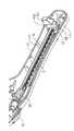
도 1a 및 도 1b는 본 발명에 따른 애플라이어의 외부 구조 및 내부 구조의 실시 예를 각각 도시한 것이다.
도 2a 및 도 2b는 본 발명에 따른 애플라이어에 적용되는 예비 유닛의 실시 예를 도시한 것이다.
도 2c 및 도 2d는 본 발명에 따른 예비 유닛에 적용되는 가이드 유닛의 실시 예를 도시한 것이다.
도 3은 본 발명에 따른 애플라이어에 수용되는 의료용 클립의 실시 예를 도시한 것이다.1A and 1B show an embodiment of an external structure and an internal structure of an Appleer according to the present invention, respectively.
2A and 2B illustrate an embodiment of a spare unit applied to an Appleer according to the present invention.
2C and 2D show an embodiment of a guide unit applied to a spare unit according to the present invention.
Figure 3 illustrates an embodiment of a medical clip accommodated in an apple lie according to the present invention.
아래에서 본 발명은 첨부된 도면에 제시된 실시 예를 참조하여 상세하게 설명이 되지만 실시 예는 본 발명의 명확한 이해를 위한 것으로 본 발명은 이에 제한되지 않는다. 아래의 설명에서 서로 다른 도면에서 동일한 도면 부호를 가지는 구성요소는 유사한 기능을 가지므로 발명의 이해를 위하여 필요하지 않는다면 반복하여 설명이 되지 않으며 공지의 구성요소는 간략하게 설명이 되거나 생략이 되지만 본 발명의 실시 예에서 제외되는 것으로 이해되지 않아야 한다.DETAILED DESCRIPTION OF THE PREFERRED EMBODIMENTS Hereinafter, the present invention will be described in detail with reference to the embodiments shown in the accompanying drawings, but the present invention is not limited thereto. In the following description, components having the same reference numerals in different drawings have similar functions, so that they will not be described repeatedly unless necessary for an understanding of the invention, and the known components will be briefly described or omitted. However, It should not be understood as being excluded from the embodiment of Fig.
도 1a 및 도 1b는 본 발명에 따른 애플라이어(10)의 외부 구조 및 내부 구조의 실시 예를 각각 도시한 것이다.1A and 1B show an embodiment of an external structure and an internal structure of the
도 1a 및 도 1b를 참조하면, 본 발명에 따른 애플라이어(10)는 내부에 클립(C)의 수용이 가능한 케이스(111); 케이스(111)에 수용된 클립(C)의 이동을 위한 이동 유닛; 케이스 (111)로부터 이동된 클립(C)이 배치되는 유도 튜브(121); 및 유도 튜브(121)에 배치된 클립(C)이 차례대로 전달되는 조 유닛(122)을 포함하고, 상기 케이스(111)에 수용된 클립(C)이 이동 유닛에 의하여 유도 튜브(121)로 모두 이동되고 그리고 유도 튜브(121)로부터 조 유닛(122)으로 클립이 차례대로 전달된다.1A and 1B, an apple
본 발명에 따른 애플라이어(10)는 다양한 규격의 의료용 클립(C)에 적용될 수 있고 예를 들어 일정한 각도로 유지되는 두 개의 분지 가지로 이루어진 의료용 클립(C)에 적용될 수 있고 이와 같은 클립의 실시 예가 도 3에서 제시된다. 의료용 클립(C)은 개복 수술 또는 복강경 수술에서 혈관 또는 조직의 결찰(Ligation)에 사용될 수 있고 티타늄과 같은 금속 또는 폴리머로 만들어질 수 있다. 본 발명에 따른 클립(C)은 임의의 소재로 만들어진 다양한 크기를 가진 클립(C)에 적용될 수 있다.The
본 발명에 따른 애플라이어(10)는 예비 유닛(11)이 클립 배치 유닛(12)에 노브 유닛(13)을 이용하여 연결된 것을 특징으로 한다. 예비 유닛(11)은 케이스(111), 케이스(111)에 배치되는 이동 유닛 및 케이스(111)에 형성된 이동 가이드(112)를 포함할 수 있다. 그리고 클립 배치 유닛(12)은 다수 개의 클립(C)이 일렬로 정렬된 유도 튜브(121) 및 유도 튜브(121)의 끝 부분에 형성된 조 유닛(122)으로 이루어질 수 있다. 그리고 노브 유닛(13)은 유도 튜브(121)를 회전 가능하도록 케이스(111)에 연결할 수 있다. 추가로 본 발명에 따른 애플라이어(10)에서 예비 유닛(11) 또는 케이스(111)는 다른 장치로부터 분리 가능하도록 만들어질 수 있다.The
아래에서 이와 같은 구조를 가지는 본 발명에 따른 애플라이어(10)에 대하여 구체적으로 설명된다.Hereinafter, the Appleer 10 according to the present invention having such a structure will be described in detail.
애플라이어(10)은 예를 들어 12 내지 18개의 클립(C)이 예비적으로 배치되는 케이스(111); 케이스(111)로부터 이동된 클립(C)이 차례대로 정렬되는 유도 튜브(121); 유도 튜브(121)로부터 하나씩 전달되는 클립(C)을 고정하여 혈관 또는 조직의 정해진 부위를 결찰시키는 조 유닛(122); 유도 튜브(121)로부터 앞쪽에 배치된 클립(C)을 차례대로 조 유닛(122)으로 이동시키는 트리거(141); 및 유도 튜브(121)를 케이스(111)에 회전 가능하도록 연결시키는 노브 유닛(13)을 포함할 수 있다.The
케이스(111)는 유도 튜브(121)에 배치되어야 할 다수 개의 클립(C)의 수용이 가능하면서 수용된 상기 다수 개의 클립(C)이 동시에 유도 튜브(121)로 이동되도록 하는 구조를 가질 수 있다. 케이스(111)는 다양한 구조를 가질 수 있고 다수 개의 클립(C)의 수용이 가능하면서 이와 동시에 다수 개의 클립(C)이 차례대로 또는 동시에 유도 튜브(121)로 이동될 수 있도록 하는 구조를 가질 수 있다. 제시된 실시 예에서 케이스(111)는 원통 또는 원통 유사 형상을 가지는 것으로 제시되어 있지만 이는 예시적인 것으로 본 발명은 제시된 실시 예에 제한되지 않는다.The
케이스(111)에 손잡이(142)가 형성될 수 있지만 이는 취급의 편의를 위한 것으로 손잡이(142)는 다양한 구조를 가질 수 있다. 필요에 따라 손잡이(142)를 통하여 클립(C)이 차례대로 케이스(111) 내부에 수용되도록 할 수 있다. 케이스(111)의 표면에 이동 가이드(112)가 형성될 수 있다. 그리고 이동 가이드(112)를 따라 푸시 유닛(113)이 이동될 수 있다.A
도 1b에 도시된 것처럼, 케이스(111)의 내부에 균형 유닛(17)이 배치될 수 있고, 균형 유닛(17)에 의하여 가이드 채널(15)이 정해진 위치에 고정될 수 있다. 가이드 채널(15)은 다수 개의 클립(C)이 일렬로 정렬되어 배치될 수 있는 구조를 가질 수 있고 예를 들어 사각형의 단면을 가지면서 직선 형상으로 연장되는 내부가 빈 막대 형상을 가질 수 있다. 그리고 일렬로 정렬된 클립(C)은 푸시 유닛((113)이 가이드 유닛을 따라 이동됨에 따라 유도 튜브(121)로 이동될 수 있다.The
유도 튜브(121)의 한쪽 끝은 가이드 채널(15)의 한쪽 끝과 연결되고, 유도 튜브(121)의 다른 끝에 조 유닛(122)이 배치될 수 있다. 유도 튜브(121)는 속이 빈 원형 또는 다각형의 단면을 가지는 튜브 형상이 될 수 있고 내부에 다수 개의 클립(C)이 일렬로 배치될 수 있는 길이로 연장될 수 있다. 유도 튜브(121)에 배치되는 클립(C)의 개수는 가이드 채널(15)에 수용된 클립(C)의 수와 동일하고 가이드 채널(15)에 수용된 클립(C)이 유도 튜브(12)로 이동될 수 있다. 유도 튜브(121)는 노브 유닛(13)에 의하여 회전 가능하도록 케이스(111)에 연결될 수 있다. 그리고 유도 튜브(121)의 내부에 배치된 클립(C)는 트리거(141)의 작동에 의하여 차례대로 조 유닛(122)으로 전달될 수 있다. 이후 조 유닛(122)에 의하여 클립(C)이 혈관 또는 인체 조직의 결찰 또는 지혈을 위하여 사용될 수 있다. 유도 튜브(12), 노브 유닛(13) 또는 조 유닛(14)은 이 분야에서 공지된 임의의 구조를 가질 수 있고 트리거(141)에 의한 클립(C)의 전달은 예를 들어 압력 또는 기계적 구동 장치에 의하여 다양한 방법으로 이루어질 수 있다.One end of the
아래에서 본 발명에 따른 애플라이어(10)에 적용될 수 있는 예비 유닛(11)에 대하여 설명된다.The following is a description of a
도 2a 및 도 2b는 본 발명에 따른 애플라이어에 적용되는 예비 유닛의 실시 예를 도시한 것이다.2A and 2B illustrate an embodiment of a spare unit applied to an Appleer according to the present invention.
도 2a를 참조하면, 푸시 유닛(113)은 한 쌍이 될 수 있고 고정 부재(23)의 양쪽에 배치될 수 있다. 그리고 고정 부재(23)에 한 쌍의 가압 블록(21a, 21b)이 결합될 수 있다. 고정 부재(23)의 중앙에 체결 홀(232)이 형성될 수 있고 그리고 체결 홀(232)의 아래쪽 및 위쪽에 고정 걸이(231a, 231b)가 형성될 수 있다. 한 쌍의 가압 블록(21a, 21b)은 서로 결합될 수 있는 베이스(214a, 214b), 하나의 베이스(214a)에 길이 방향으로 형성된 이동 홈(212) 및 다른 베이스(214b)에 형성된 접촉 돌기(211)를 포함할 수 있다. 그리고 각각의 베이스(214a, 214b)의 외부에 결합 홈(213a, 213b)이 형성될 수 있다. 한 쌍의 가압 블록(21a, 21b)은 각각의 베이스(214a, 214b)가 서로 접촉되어 체결 홀(232)에 삽입되는 형태로 결합되어 한 쌍의 고정 걸이(231a, 231b)에 의하여 고정될 수 있다. 가압 블록(21a, 21b)이 결합된 상태에서 접촉 돌기(211)가 이동 홈(212)에 위치하게 된다. 가압 블록(21a, 21b)에 형성된 결함 홈(213a, 213b)은 각각 케이스의 내부에 배치된 이동 부재에 결합될 수 있다. 이와 같은 상태에서 푸시 유닛(113)이 수동 또는 자동으로 작동될 수 있고 이에 따라 고정 부재(23) 및 가압 유닛(21a, 21b)은 이동 부재에 결합된 결합 홈(213a, 213b)에 의하여 가이드 채널(15)을 따라 이동될 수 있다. 그리고 접촉 돌기(211)가 클립(C)에 접촉되어 가이드 채널(15)을 따라 클립(C)이 이동될 수 있다.2A, the
가이드 채널(15)의 앞쪽에 회전 부재(22)가 배치될 수 있고 회전 부재(22)에 의하여 가이드 채널(15)이 유도 튜브(121)에 연결될 수 있다. 그리고 푸시 유닛(113)이 유도 튜브(121)의 방향으로 이동됨에 따라 가이드 채널(15)에 수용된 클립(C)이 유도 튜브(121)로 이동될 수 있다. 푸시 유닛(113)의 이동 범위는 가이드 채널(15)에 수용된 모든 클립(C)이 유도 튜브(121)의 내부로 이동되도록 설정될 수 있다.The
삭제delete
다양한 클립 이동 구조가 본 발명에 따른 애플라이어에 적용될 수 있고 본 발명은 제시된 실시 예에 제한되지 않는다.Various clip movement schemes may be applied to the appliers according to the present invention and the present invention is not limited to the embodiments shown.
도 2c 및 도 2d는 본 발명에 따른 예비 유닛에 적용되는 가이드 유닛의 실시 예를 도시한 것이다.2C and 2D show an embodiment of a guide unit applied to a spare unit according to the present invention.
도 2c를 참조하면, 가이드 채널(15)의 내부에 제한 플레이트(24)가 형성되어 가이드 채널(15)의 내부에 배치된 클립(C)이 안정적으로 배치되도록 할 수 있다. 클립(C)이 가이드 채널(15)의 내부에 수용된 상태에서 클립(C)은 조 유닛에 전달되는 상태로 유지된다. 그리고 이와 같은 상태에서 클립(C)은 운반, 저장, 살균 또는 멸균 과정에 처해지게 된다. 이로 인하여 클립(C)의 물리적 상태는 조 유닛에 전달되는 상태로 유지될 수 있고 클립(C)이 조 유닛으로부터 이탈되는 것이 방지될 수 있다. 이를 위하여 가이드 채널(15)의 폭은 조 유닛에서 클립(C)이 고정되는 상태에 따라 결정될 수 있다.Referring to FIG. 2C, a
도 2d를 참조하면, 가이드 채널(15)과 유도 튜브가 연결되는 부분에 폭 조절 영역(26)이 형성될 수 있다. 폭 조절 영역(26)의 끝 부분은 유도 튜브의 폭과 동일 또는 유사하도록 설정될 수 있다. 일반적으로 유도 튜브에서 클립(C)은 양쪽 가지가 접근한 상태로 유지될 수 있다. 그리고 유도 튜브로부터 조 유닛으로 클립(C)이 전달되고 결찰 또는 파지가 되는 과정에서 클립(C)의 양쪽 가지가 이격될 수 있다. 만약 클립(C)이 유도 튜브에 장시간 동안 고정이 되거나 또는 유도 튜브에 배치된 상태에서 멸균 또는 살균을 위하여 고온 상태로 일정 시간 유지되면 클립(C)이 탄성을 잃게 되거나 또는 다른 물리적 특성이 변성될 수 있다. 그리고 클립(C)이 요구되는 형태로 동작되지 않을 수 있다. 본 발명에 따른 애플라이어는 이와 같은 클립의 물리적 특성을 변형을 방지하여 클립(C)이 안정적으로 동작하도록 한다.Referring to FIG. 2D, a
가이드 채널(15)은 이와 같은 클립(C)의 사용 상태에 따라 적절한 폭을 가질 수 있다.The
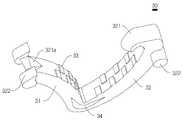
아래에서 본 발명에 따른 애플라이어에 적용될 수 있는 클립(C)의 실시 예를 도시한 것이다.Below is shown an embodiment of a clip (C) that may be applied to an apple according to the present invention.
도 3은 본 발명에 따른 애플라이어에 수용되는 의료용 클립의 실시 예를 도시한 것이다.Figure 3 illustrates an embodiment of a medical clip accommodated in an apple lie according to the present invention.
도 3을 참조하면, 본 발명에 따른 애플라이어에 적용될 수 있는 의료용 클립(30)은 탄성을 가지는 폴리머, 금속 또는 비금속 소재로 만들어질 수 있고 탄성에 의하여 일정한 범위의 분리 각을 형성하는 한 쌍의 분리 가지(31, 32)를 포함할 수 있다. 한 쌍의 분리 가지(31,32)의 각각은 예를 들어 원형 단면 또는 다각형 단면을 가지는 막대 형상이 될 수 있고 한쪽 끝이 서로 연결될 수 있다. 그리고 연결된 한쪽 끝 부분의 측면에 관통 여유 공간(34)이 형성될 수 있다. 여유 공간은 연결 부분을 기준으로 서로 다른 형상을 가질 수 있고 예를 들어 각각의 분리 가지(31, 32)의 연장 길이, 단면적 크기 또는 근접 과정에서 상대적인 이동 거리를 고려하여 적절하게 결정될 수 있다. 예를 들어 제1 분리 가지(31)가 제2 분리 가지(32)에 비하여 연장 길이가 작다면, 관통 여유 공간(34)은 제1 분리 가지(31)의 방향으로 상대적으로 큰 폭과 작은 길이로 연장될 수 있다.Referring to FIG. 3, the
한 쌍의 분리 가지(31, 32)의 양쪽 끝에 각각 고정 홈(321a) 및 걸이 훅(321)이 형성될 수 있다. 결찰 과정에서 한 쌍의 분리 가지(32)의 양쪽 끝은 서로 결합이 되고 이로 인하여 각각의 분리 가지(31)의 안쪽 면이 근접하게 된다. 그리고 수술 과정에서 이와 같은 상태가 유지되어 혈관에 대한 지혈 또는 고정이 이루어질 필요가 있다. 고정 홈(321a)과 걸이 훅(321)은 이와 같이 한 쌍의 분리 가지(31, 32)가 근접되어 고정되는 상태가 유지되도록 한다.Fixing
고정 홈(321a)은 쐐기 형상으로 만들어질 수 있고, 걸이 훅(321)은 갈고리 형상으로 만들어질 수 있다. 구체적으로 고정 홈(32)은 삼각형 형상의 두 개의 면이 아래쪽으로 연장되면서 분리 가지의 바깥쪽으로 가면서 폭이 넓어지는 쐐기 형상이 될 수 있다. 그리고 걸이 훅(321)은 안쪽으로 휘어지면서 날카로운 끝은 형성하는 구조를 가질 수 있다. 필요에 따라 분리 가지(31, 32)의 양쪽 끝에 균형 유닛(322)이 형성될 수 있다. 균형 유닛(322)은 분리 가지(31, 32)의 양쪽 끝이 다른 부분에 비하여 상대적으로 무거워지도록 하고 이로 인하여 고정 홈(321a)과 걸이 훅(321)의 결합이 안정적으로 유지될 수 있도록 한다.The fixing
각각의 분리 가지(31, 32)의 서로 마주보는 안쪽 면에 다수 개의 단차 블록(33)이 형성될 수 있다. 단차 블록(33)은 고정되는 인체 내부의 기관의 표면이 미끄럽고 이로 인하여 클립(30)이 예를 들어 혈관을 따라 이동 또는 미끄러지는 것을 방지되도록 한다. 달리 말하면 결찰의 안정성이 보장되도록 한다.A plurality of step blocks 33 may be formed on the inner surfaces of the
단차 블록(33)은 사각 판형이 될 수 있고 한쪽 변이 안쪽 면의 바깥 변을 공유하도록 형성될 수 있다. 그리고 안쪽 면의 양쪽 변을 따라 서로 엇갈리도록 다수 개가 배치될 수 있다. 각각의 단차 블록(33)의 안쪽으로 연장되는 길이는 특별히 제한되지 않는다. 그리고 단차 블록(33)의 높이는 결찰이 되는 부위의 단면적 또는 소재의 특성에 따라 적절하게 설정될 수 있다. 다양한 단차 블록(33)이 각각의 분리 가지(31, 32)의 안쪽 면에 형성될 수 있다.The
본 발명에 따른 애플라이어는 의료용 클립(30)의 분리 가지(31, 32)가 요구되는 상태로 작동되도록 한다.The applier according to the present invention allows the
본 발명에 따른 애플라이어는 살균 또는 멸균 과정에서 클립의 물리적 특성이 변화되는 것이 방지되도록 하고 이로 인하여 클립이 조 유닛(jaw unit)으로부터 분리되는 것이 방지되도록 한다. 또한 수술 과정에서 클립이 조 유닛(jaw unit)으로 이동되도록 하는 것에 의하여 클립의 불량이 감소되도록 한다. 추가로 본 발명에 따른 애플라이어는 클립에 필요한 위생적 처리가 간단하게 이루어질 수 있도록 한다. The appliers according to the present invention prevent the physical properties of the clip from changing during the sterilization or sterilization process, thereby preventing the clip from being separated from the jaw unit. In addition, by allowing the clip to move to the jaw unit during the surgical procedure, the defects of the clip are reduced. In addition, the applier according to the present invention makes it possible to simplify the sanitary treatment required for the clip.
위에서 본 발명은 제시된 실시 예를 참조하여 상세하게 설명이 되었지만 이 분야에서 통상의 지식을 가진 자는 제시된 실시 예를 참조하여 본 발명의 기술적 사상을 벗어나지 않는 범위에서 다양한 변형 및 수정 발명을 만들 수 있을 것이다. 본 발명은 이와 같은 변형 및 수정 발명에 의하여 제한되지 않으며 다만 아래에 첨부된 청구범위에 의하여 제한된다.While the present invention has been particularly shown and described with reference to exemplary embodiments thereof, it will be understood by those of ordinary skill in the art that various changes in form and details may be made therein without departing from the spirit and scope of the invention . The invention is not limited by these variations and modifications, but is limited only by the claims appended hereto.
10: 클립 애플라이어 11: 예비 유닛
12: 클립 배치 유닛 13: 노브 유닛
15: 가이드 채널 17: 균형 유닛
21a, 21b: 가압 블록 23: 고정 부재
24: 제한 플레이트 26: 폭 조절 영역
30: 클립 31, 32: 분리 가지
33: 단차 블록 34: 관통 여유 공간
111: 케이스 112: 이동 가이드
113: 푸시 유닛 121: 유도 튜브
122: 조 유닛 141: 트리거
142: 손잡이 171: 받침 플레이트
214a, 214b: 베이스 211: 접촉 돌기
212: 이동 홈 213a, 213b: 결합 홈
231a, 231b: 고정 걸이 232: 체결 홀
321a: 고정 홈 321: 걸이 훅10: Clip applier 11: Spare unit
12: clip arrangement unit 13: knob unit
15: Guide channel 17: Balancing unit
21a, 21b: pressing block 23: fixing member
24: limiting plate 26: width adjusting area
30:
33: Step block 34: Through hole clearance
111: Case 112: Moving Guide
113: push unit 121: guide tube
122: coarse unit 141: trigger
142: handle 171:
214a, 214b: base 211: contact projection
212: moving
231a, 231b: fixing hook 232: fastening hole
321a: Fixing groove 321: Hook hook
Claims (4)
Translated fromKorean케이스(111)의 내부에 배치되면서 다수 개의 클립(C)이 일렬로 배치되도록 길이 방향으로 연장되는 구조로 만들어지는 가이드 채널(15);
노브 유닛(13)에 의하여 가이드 채널(15)의 한쪽 끝과 연결되고, 내부에 상기 다수 개의 클립(C)이 일렬로 배치되는 길이로 연장되는 유도 튜브(121);
가이드 채널(15)의 내부에 배치되는 제한 플레이트(24)에 연결되면서 케이스(111)의 덮개에 외부로 돌출되어 케이스(111)의 덮개 외부에 형성된 이동 가이드(112)를 따라 이동하면서 가이드 채널(15) 내의 클립(C)을 유도 튜브(121)로 이동시키는 푸시 유닛(113);
가이드 채널(15)과 유도 튜브(121)를 연결하면서 끝 부분이 유도 튜브(121)의 폭과 동일하도록 형성된 폭 조절 영역(26); 및
케이스(111)에 설치된 트리거(141)의 작동에 의하여 상기 다수 개의 클립(C)이 차례대로 이동되는 조 유닛(122)을 포함하고,
상기 가이드 채널(15)의 내부에 수용된 상태에서 상기 다수 개의 클립(C)은 조 유닛(122)에 전달되는 상태로 유지되어, 각각의 클립(C)이 조 유닛(122)으로부터 이탈이 방지되는 것을 특징으로 하는 의료용 오토메틱 클립 애플라이어.A case 111;
A guide channel (15) arranged inside the case (111) and made to have a structure extending in the longitudinal direction so that a plurality of clips (C) are arranged in a row;
A guide tube (121) connected to one end of the guide channel (15) by a knob unit (13) and extending in a length in which the plurality of clips (C) are arranged in a row;
And is connected to the restriction plate 24 disposed inside the guide channel 15 and protrudes outward from the cover of the case 111 to move along the movement guide 112 formed on the outside of the cover of the case 111, A push unit 113 for moving the clip C in the guide tube 121 to the guide tube 121;
A width adjusting region 26 connecting the guide channel 15 and the guide tube 121 so that an end portion thereof is equal to a width of the guide tube 121; And
And a jaw unit (122) in which the plurality of clips (C) are sequentially moved by operation of a trigger (141) provided on the case (111)
The plurality of clips C are held in a state of being transferred to the jaw unit 122 while being accommodated in the guide channel 15 so that the respective clips C are prevented from being separated from the jaw unit 122 A medical automatic clip applier featuring a.
The medical automatic clip applier according to claim 1, wherein the width of the guide channel (15) is larger than the width of the guide tube (121).
Priority Applications (2)
| Application Number | Priority Date | Filing Date | Title |
|---|---|---|---|
| KR1020140149830AKR101649718B1 (en) | 2014-10-31 | 2014-10-31 | An Automatic Clip Applier for a Surgical Operation |
| PCT/KR2014/010765WO2016068372A1 (en) | 2014-10-31 | 2014-11-10 | Medical automatic clip applier |
Applications Claiming Priority (1)
| Application Number | Priority Date | Filing Date | Title |
|---|---|---|---|
| KR1020140149830AKR101649718B1 (en) | 2014-10-31 | 2014-10-31 | An Automatic Clip Applier for a Surgical Operation |
Publications (2)
| Publication Number | Publication Date |
|---|---|
| KR20160050802A KR20160050802A (en) | 2016-05-11 |
| KR101649718B1true KR101649718B1 (en) | 2016-08-19 |
Family
ID=55857700
Family Applications (1)
| Application Number | Title | Priority Date | Filing Date |
|---|---|---|---|
| KR1020140149830AExpired - Fee RelatedKR101649718B1 (en) | 2014-10-31 | 2014-10-31 | An Automatic Clip Applier for a Surgical Operation |
Country Status (2)
| Country | Link |
|---|---|
| KR (1) | KR101649718B1 (en) |
| WO (1) | WO2016068372A1 (en) |
Cited By (1)
| Publication number | Priority date | Publication date | Assignee | Title |
|---|---|---|---|---|
| KR102315685B1 (en) | 2021-02-09 | 2021-10-21 | (주)유원메디텍 | Automatic Polymer Clip Applier |
Families Citing this family (2)
| Publication number | Priority date | Publication date | Assignee | Title |
|---|---|---|---|---|
| WO2019031620A1 (en)* | 2017-08-08 | 2019-02-14 | 주식회사 엔도비전 | Hemostatic clip providing device |
| CN112704539B (en)* | 2019-10-25 | 2023-02-24 | 苏州英途康医疗科技有限公司 | Clip applier shaft assembly and medical surgical clip applier |
Citations (2)
| Publication number | Priority date | Publication date | Assignee | Title |
|---|---|---|---|---|
| JP2012030090A (en) | 2004-10-08 | 2012-02-16 | Tyco Healthcare Group Lp | Endoscopic surgical clip applier |
| JP2012130714A (en)* | 2003-12-10 | 2012-07-12 | Medtronic Inc | Surgical connection apparatus |
Family Cites Families (4)
| Publication number | Priority date | Publication date | Assignee | Title |
|---|---|---|---|---|
| JPH06237938A (en)* | 1993-02-12 | 1994-08-30 | Olympus Optical Co Ltd | Clip device |
| US6306149B1 (en)* | 2000-02-15 | 2001-10-23 | Microline, Inc. | Medical clip device with cyclical pusher mechanism |
| US7297149B2 (en)* | 2005-04-14 | 2007-11-20 | Ethicon Endo-Surgery, Inc. | Surgical clip applier methods |
| EP2157920B1 (en)* | 2007-03-26 | 2017-09-27 | Covidien LP | Endoscopic surgical clip applier |
- 2014
- 2014-10-31KRKR1020140149830Apatent/KR101649718B1/ennot_activeExpired - Fee Related
- 2014-11-10WOPCT/KR2014/010765patent/WO2016068372A1/enactiveApplication Filing
Patent Citations (2)
| Publication number | Priority date | Publication date | Assignee | Title |
|---|---|---|---|---|
| JP2012130714A (en)* | 2003-12-10 | 2012-07-12 | Medtronic Inc | Surgical connection apparatus |
| JP2012030090A (en) | 2004-10-08 | 2012-02-16 | Tyco Healthcare Group Lp | Endoscopic surgical clip applier |
Cited By (1)
| Publication number | Priority date | Publication date | Assignee | Title |
|---|---|---|---|---|
| KR102315685B1 (en) | 2021-02-09 | 2021-10-21 | (주)유원메디텍 | Automatic Polymer Clip Applier |
Also Published As
| Publication number | Publication date |
|---|---|
| KR20160050802A (en) | 2016-05-11 |
| WO2016068372A1 (en) | 2016-05-06 |
Similar Documents
| Publication | Publication Date | Title |
|---|---|---|
| ES2881527T3 (en) | Spring Release Surgical Staple | |
| JP7066895B2 (en) | Clip applier with stabilizing member | |
| KR102401230B1 (en) | Polymer Ligation Clips | |
| KR101965936B1 (en) | A Jaw Module for Preventing a Clip from Slipping in a Clip Applier and the Clip Applier for the Same | |
| CN110856662A (en) | Surgical clip applier and ligating clip | |
| CN110063767B (en) | Ligating clip with tissue retaining feature | |
| JP2023009051A (en) | Flexible stabilizing member for clip applier | |
| US11291459B2 (en) | Latching wire clip | |
| US20170340331A1 (en) | Surgical clip applier with multiple clip feeding mechanism | |
| US20110066163A1 (en) | Hemostatic Clip and Hemostatic Clip Operation Apparatus Using the Same | |
| US11883034B2 (en) | Clip cartridge | |
| US20060161182A1 (en) | Single fire vascular clip applier with disposable jaw | |
| NO822893L (en) | HEMOSTATIC CLAMP WITH LOCKING TENSION DEVICE. | |
| KR101649718B1 (en) | An Automatic Clip Applier for a Surgical Operation | |
| US9332989B2 (en) | Surgical instrument for removing surgical clips | |
| KR101966939B1 (en) | clip applier having jaw guide | |
| US11395660B2 (en) | Stackable ligation clip | |
| KR20190087707A (en) | An Applier for a Medical Clip | |
| JP5595094B2 (en) | Suture retainer for unligated internal sutures | |
| US20210007751A1 (en) | Clip applier | |
| EP4033956A1 (en) | Clip applier | |
| US11602455B2 (en) | Cannula tool and method | |
| US10478164B2 (en) | Jaw for a surgical tubular shaft instrument | |
| KR101715724B1 (en) | A Ligation Clip for Surgery | |
| JP2023080097A (en) | Clip applier with stabilizing member |
Legal Events
| Date | Code | Title | Description |
|---|---|---|---|
| A201 | Request for examination | ||
| PA0109 | Patent application | St.27 status event code:A-0-1-A10-A12-nap-PA0109 | |
| PA0201 | Request for examination | St.27 status event code:A-1-2-D10-D11-exm-PA0201 | |
| E902 | Notification of reason for refusal | ||
| PE0902 | Notice of grounds for rejection | St.27 status event code:A-1-2-D10-D21-exm-PE0902 | |
| P22-X000 | Classification modified | St.27 status event code:A-2-2-P10-P22-nap-X000 | |
| AMND | Amendment | ||
| E13-X000 | Pre-grant limitation requested | St.27 status event code:A-2-3-E10-E13-lim-X000 | |
| P11-X000 | Amendment of application requested | St.27 status event code:A-2-2-P10-P11-nap-X000 | |
| P13-X000 | Application amended | St.27 status event code:A-2-2-P10-P13-nap-X000 | |
| PG1501 | Laying open of application | St.27 status event code:A-1-1-Q10-Q12-nap-PG1501 | |
| E601 | Decision to refuse application | ||
| PE0601 | Decision on rejection of patent | St.27 status event code:N-2-6-B10-B15-exm-PE0601 | |
| R18-X000 | Changes to party contact information recorded | St.27 status event code:A-3-3-R10-R18-oth-X000 | |
| AMND | Amendment | ||
| E13-X000 | Pre-grant limitation requested | St.27 status event code:A-2-3-E10-E13-lim-X000 | |
| P11-X000 | Amendment of application requested | St.27 status event code:A-2-2-P10-P11-nap-X000 | |
| P13-X000 | Application amended | St.27 status event code:A-2-2-P10-P13-nap-X000 | |
| PX0901 | Re-examination | St.27 status event code:A-2-3-E10-E12-rex-PX0901 | |
| PX0701 | Decision of registration after re-examination | St.27 status event code:A-3-4-F10-F13-rex-PX0701 | |
| X701 | Decision to grant (after re-examination) | ||
| PR0701 | Registration of establishment | St.27 status event code:A-2-4-F10-F11-exm-PR0701 | |
| PR1002 | Payment of registration fee | St.27 status event code:A-2-2-U10-U11-oth-PR1002 Fee payment year number:1 | |
| PG1601 | Publication of registration | St.27 status event code:A-4-4-Q10-Q13-nap-PG1601 | |
| R18-X000 | Changes to party contact information recorded | St.27 status event code:A-5-5-R10-R18-oth-X000 | |
| PC1903 | Unpaid annual fee | St.27 status event code:A-4-4-U10-U13-oth-PC1903 Not in force date:20190813 Payment event data comment text:Termination Category : DEFAULT_OF_REGISTRATION_FEE | |
| PC1903 | Unpaid annual fee | St.27 status event code:N-4-6-H10-H13-oth-PC1903 Ip right cessation event data comment text:Termination Category : DEFAULT_OF_REGISTRATION_FEE Not in force date:20190813 | |
| R18-X000 | Changes to party contact information recorded | St.27 status event code:A-5-5-R10-R18-oth-X000 |