KR101649713B1 - Biopsy device and system - Google Patents
Biopsy device and systemDownload PDFInfo
- Publication number
- KR101649713B1 KR101649713B1KR1020140043035AKR20140043035AKR101649713B1KR 101649713 B1KR101649713 B1KR 101649713B1KR 1020140043035 AKR1020140043035 AKR 1020140043035AKR 20140043035 AKR20140043035 AKR 20140043035AKR 101649713 B1KR101649713 B1KR 101649713B1
- Authority
- KR
- South Korea
- Prior art keywords
- needle
- passage
- cutter
- flexible tube
- tissue
- Prior art date
- Legal status (The legal status is an assumption and is not a legal conclusion. Google has not performed a legal analysis and makes no representation as to the accuracy of the status listed.)
- Active
Links
Images


Classifications
- A—HUMAN NECESSITIES
- A61—MEDICAL OR VETERINARY SCIENCE; HYGIENE
- A61B—DIAGNOSIS; SURGERY; IDENTIFICATION
- A61B10/00—Instruments for taking body samples for diagnostic purposes; Other methods or instruments for diagnosis, e.g. for vaccination diagnosis, sex determination or ovulation-period determination; Throat striking implements
- A61B10/02—Instruments for taking cell samples or for biopsy
- A61B10/0233—Pointed or sharp biopsy instruments
- A61B10/0266—Pointed or sharp biopsy instruments means for severing sample
- A61B10/0275—Pointed or sharp biopsy instruments means for severing sample with sample notch, e.g. on the side of inner stylet
- A—HUMAN NECESSITIES
- A61—MEDICAL OR VETERINARY SCIENCE; HYGIENE
- A61B—DIAGNOSIS; SURGERY; IDENTIFICATION
- A61B10/00—Instruments for taking body samples for diagnostic purposes; Other methods or instruments for diagnosis, e.g. for vaccination diagnosis, sex determination or ovulation-period determination; Throat striking implements
- A61B10/02—Instruments for taking cell samples or for biopsy
- A61B10/0233—Pointed or sharp biopsy instruments
- A61B10/0283—Pointed or sharp biopsy instruments with vacuum aspiration, e.g. caused by retractable plunger or by connected syringe
- A—HUMAN NECESSITIES
- A61—MEDICAL OR VETERINARY SCIENCE; HYGIENE
- A61B—DIAGNOSIS; SURGERY; IDENTIFICATION
- A61B10/00—Instruments for taking body samples for diagnostic purposes; Other methods or instruments for diagnosis, e.g. for vaccination diagnosis, sex determination or ovulation-period determination; Throat striking implements
- A61B10/02—Instruments for taking cell samples or for biopsy
- A61B2010/0208—Biopsy devices with actuators, e.g. with triggered spring mechanisms
- A—HUMAN NECESSITIES
- A61—MEDICAL OR VETERINARY SCIENCE; HYGIENE
- A61B—DIAGNOSIS; SURGERY; IDENTIFICATION
- A61B10/00—Instruments for taking body samples for diagnostic purposes; Other methods or instruments for diagnosis, e.g. for vaccination diagnosis, sex determination or ovulation-period determination; Throat striking implements
- A61B10/02—Instruments for taking cell samples or for biopsy
- A61B2010/0225—Instruments for taking cell samples or for biopsy for taking multiple samples
Landscapes
- Health & Medical Sciences (AREA)
- Life Sciences & Earth Sciences (AREA)
- Medical Informatics (AREA)
- Engineering & Computer Science (AREA)
- Biomedical Technology (AREA)
- Heart & Thoracic Surgery (AREA)
- Pathology (AREA)
- Molecular Biology (AREA)
- Surgery (AREA)
- Animal Behavior & Ethology (AREA)
- General Health & Medical Sciences (AREA)
- Public Health (AREA)
- Veterinary Medicine (AREA)
- Surgical Instruments (AREA)
- Sampling And Sample Adjustment (AREA)
Abstract
Translated fromKorean
Description
Translated fromKorean본 발명은 생체 검사 장치 및 시스템에 관한 것으로, 보다 상세하게는 인체 조직을 절개하여 조직 시료(Tissue sample)를 효율적으로 채취하기 위한 생체 검사 장치 및 시스템에 관한 것이다.BACKGROUND OF THE INVENTION 1. Field of the Invention [0001] The present invention relates to a biological test apparatus and system, and more particularly, to a biological test apparatus and system for efficiently sampling a tissue sample by cutting a human tissue.
생체 검사는 환자의 병변(Lesion) 부위의 생체 세포, 조직 등을 채취한 후 그 시료를 분석하여 진단하는 조직학적 검사(Histopathological examination) 중 하나이다. 생체 검사는 주로 암과 같은 질환이 의심되는 경우에 행해지며, 절제 생체 검사(Excisional biopsy), 절개 생체 검사(Incisional biopsy), 경피 생체 검사(Percutaneous biopsy) 등으로 구분되고 있다.A biopsy is one of the histopathological examinations that analyze the sample after collecting the living cells, tissues, etc. of the lesion site of the patient. Biopsy is performed mainly when a disease such as cancer is suspected. It is divided into excisional biopsy, incisional biopsy, and percutaneous biopsy.
생체 검사 장치 및 방법에 대한 기술은 미국 특허 제5,526,822호 "Method and apparatus for automated biopsy and collection of soft tissue", 미국 특허 제5,775,333호 "Apparatus for automated biopsy and collection of soft tissue", 미국 특허 제6,086,544호 "Control apparatus for an automated surgical biopsy device", 미국 특허 제6,485,436호 "Pressure-assisted biopsy needle apparatus and technique", 미국 특허 제7,419,472호 "Biopsy instrument with internal specimen collection mechanism", 미국 특허 제8,177,728호 "Valve mechanism for tetherless biopsy device", 미국 특허 제8,206,316호 "Tetherless biopsy device with reusable portion" 등 많은 특허 문헌에 개시되어 있다. 위 특허 문헌들 각각의 개시 내용은 본 명세서에 참고로 포함된다.Techniques for biopsy devices and methods are described in U.S. Patent No. 5,526,822 entitled " Method and Apparatus for Automated Biopsy and Collection of Soft Tissue ", U.S. Patent No. 5,775,333 entitled " Apparatus for automated biopsy and collection of soft tissue ", U.S. Patent No. 6,086,544 US-A-6,485,436 "Pressure-assisted biopsy needle apparatus and technique ", U.S. Patent No. 7,419,472" Biopsy instrument with internal specimen collection mechanism ", U.S. Patent No. 8,177,728 "Valve mechanism for tetherless biopsy device ", US Patent No. 8,206,316, "Tetherless biopsy device with reusable portion ", and the like. The disclosures of each of the above patents are incorporated herein by reference.
몇몇 특허 문헌들의 생체 검사 장치는 하우징(Housing), 니들(Needle), 커터(Cutter), 커터 드라이버(Cutter driver)와 진공 체임버(Vacuum chamber)를 포함하고 있다. 니들은 하우징으로부터 연장되어 있으며, 통로(Passageway), 조직 수취 포트(Tissue receiving port) 또는 개구(Opening)를 구비한다. 커터는 니들의 통로 안에 조직의 절단을 위하여 회전 및 병진이동할 수 있도록 배치되어 있고 니들의 통로와 연통되는 통로를 구비한다. 진공 체임버는 커터의 통로에 연결되어 있으며, 절단되어 있는 조직 시료의 채취를 위하여 조직 수취 포트로부터 니들과 커터의 통로들을 따라 조직 시료를 수송하여 커터 밖으로 배출한다. 커터 밖으로 배출되는 조직 시료는 트레이(Tray), 카트리지(Cartage)에 수집된다. 진공 체임버 또는 진공원(Vacuum source)는 공기의 흡인력을 발생하는 진공펌프(Vacuum pump)를 구비하고 있다.Some bio-inspection devices of patent documents include a housing, a needle, a cutter, a cutter driver, and a vacuum chamber. The needle extends from the housing and has a passageway, a tissue receiving port or an opening. The cutter has a passage arranged to be able to rotate and translate for cutting of tissue in the passage of the needle and to communicate with the passage of the needle. The vacuum chamber is connected to the passage of the cutter and transports the tissue sample along the passages of the needle and cutter from the tissue receiving port to extract the cut tissue sample and discharges it out of the cutter. Tissue samples discharged from the cutter are collected in a tray and a cartridge. A vacuum chamber or a vacuum source is equipped with a vacuum pump which generates a suction force of air.
그러나 상기한 바와 같은 종래의 생체 검사 장치는 진공펌프의 구동에 의하여 진공압(Vacuum pressure)을 발생시켜 니들과 커터의 통로들을 따라 조직 시료를 수송할 때 조직 시료의 수송 방향 후단에 낮은 압력이 작용되어 조직 시료의 수송이 원활하지 못한 문제가 있다. 니들 및 커터의 통로들이 조직 시료에 의하여 막히는 경우, 새로운 생체 검사 장치를 사용하여 조직 시료를 다시 채취해야만 한다.However, in the conventional biopsy device, when a tissue sample is transported along the passages of the needle and the cutter by generating a vacuum pressure by driving the vacuum pump, a low pressure acts on the trailing end of the tissue sample in the transport direction And there is a problem that the transportation of the tissue sample is not smooth. If the needle and cutter passageways are clogged by the tissue sample, the tissue sample must be sampled again using a new biopsy device.
한편, 조직 시료의 채취를 원활하게 실시하기 위하여 미국 특허 제7,419,472호는 니들과 커터의 통로들을 따라 병진이동할 수 있도록 배치되어 있는 플렉시블 푸시로드(Flexible push rod)를 구비하고 있다. 푸시로드는 조직 시료의 수송 시 조직 시료의 수송 방향 후단을 밀어 조직 시료의 수송을 보조한다. 그러나 푸시로드의 기구적인 작동을 위한 웜기어(Worm gear), 드라이브 블록(Drive block) 등으로 구성되는 드라이브 메커니즘(Drive mechanism)의 구성이 복잡하고, 조립 공정이 복잡하여 생산비가 높은 문제가 있다.In order to smoothly collect a tissue sample, U.S. Patent No. 7,419,472 has a flexible push rod arranged to be translationally moved along the passages of the needle and the cutter. The push rod assists in transporting the tissue sample by pushing the trailing end of the tissue sample in the transport direction of the tissue sample. However, there is a problem in that the structure of a drive mechanism composed of a worm gear, a drive block, and the like for the mechanical operation of the push rod is complicated and the assembling process is complicated, resulting in a high production cost.
미국 특허 제6,485,436호는 시료 수취 포트와 연통되어 있는 유입 통로(Inflow passageway or channel)에 연결되어 있는 여압원(Pressurization source)을 구비하고 있다. 여압원은 조직 시료의 수송 시 유입 통로를 통하여 생체에 적합한 가스, 액체의 고압 흐름(High pressure flow)을 시료 수취 포트에 배송(Delivering)함으로써 조직 시료의 수송을 보조한다. 그러나 가스, 액체의 고압 흐름을 배송하기 위하여 고가의 여압원이 사용될 뿐만 아니라, 여압원과 유입 통로의 연결을 위한 피팅(Fitting) 등의 부품이 사용되어 생산비가 높은 문제가 있다.U.S. Patent No. 6,485,436 has a pressurization source connected to an inflow passageway or channel in communication with the sample receiving port. The pressurization source assists in transporting the tissue sample by delivering a high pressure flow of the gas and liquid suitable for the living body to the sample receiving port through the inflow channel when the tissue sample is transported. However, in order to deliver the high-pressure flow of gas and liquid, there is a problem in that an expensive pressurizing source is used, and parts such as a fitting for connecting the pressurizing source and the inflow passage are used, resulting in a high production cost.
본 발명은 상기와 같은 종래 생체 검사 장치의 여러 가지 문제점을 해결하기 위한 것이다. 본 발명의 목적은, 조직 시료의 수송을 위하여 조직 시료의 수송 방향 선단 및 후단에 압력차를 발생시킬 수 있는 새로운 생체 검사 장치 및 시스템을 제공하는 것이다.The present invention is intended to solve various problems of the conventional biometric test apparatus. An object of the present invention is to provide a new bio-inspection apparatus and system capable of generating a pressure difference at the front and rear ends of a tissue sample in the transport direction for transporting the tissue sample.
본 발명의 다른 목적은, 진공원의 흡인에 의하여 조직 시료의 수송 방향 선단에 저압이 조성되는 것에 반하여 조직 시료의 수송 방향 후단에 대기압이 조성되어 조직 시료의 수송을 원활하게 실시할 수 있는 생체 검사 장치 및 시스템을 제공하는 것이다.Another object of the present invention is to provide a biosensor capable of smoothly transporting a tissue sample by forming an atmospheric pressure downstream of a transport direction of a tissue sample while a low pressure is formed at the tip of the tissue sample in the transport direction by suction of a vacuum source Apparatus and system.
본 발명의 또 따른 목적은, 플렉시블 튜브와 솔레노이드 액추에이터의 간단한 구성과 저가의 부품에 의하여 조직 시료의 수송 방향 후단을 대기압으로 조성할 수 있으므로, 생산비를 절감할 수 있는 생체 검사 장치 및 시스템을 제공하는 것이다.It is a further object of the present invention to provide a biometric test apparatus and system capable of reducing the production cost since a simple constitution of a flexible tube and a solenoid actuator and an inexpensive component can constitute the rear end of the tissue sample in the transport direction, will be.
본 발명의 또 다른 목적은, 커터의 회전과 병진이동을 위한 전기모터의 구동력이 단일의 기어열에 의하여 전달되는 간단한 구조에 의하여 조립성이 향상되고, 생산비를 절감할 수 있는 생체 검사 장치 및 시스템을 제공하는 것이다.It is still another object of the present invention to provide a biometric test apparatus and system capable of improving assembling performance and reducing a production cost by a simple structure in which a driving force of an electric motor for rotating and translating a cutter is transmitted by a single gear train .
본 발명의 일 측면에 따르면, 조직을 절단하여 조직 시료를 채취하기 위한 생체 검사 장치가 제공된다. 본 발명에 따른 생체 검사 장치는, 팁에 의하여 막혀 있는 근위단부와, 원위단부와, 통로와, 조직의 유입을 위하여 원위단부와 이웃하는 외면에 통로와 연통되도록 형성되어 있는 시료 수취 포트를 구비하는 니들과; 니들의 통로에 회전 및 병진이동할 수 있도록 배치되어 있고, 니들의 통로 안에 배치되어 있는 근위단부와, 니들의 통로 밖에 배치되어 있는 원위단부와, 니들의 통로와 연통되어 있는 통로를 구비하는 커터와; 커터를 회전 및 병진이동시키는 드라이브 메커니즘과; 조직 및 조직 시료의 흡인을 위하여 커터의 통로와 연결되어 있는 진공 라인과; 조직 시료의 흡인 시 조직 시료의 수송 방향 후단과 이웃하는 니들의 통로 안을 대기압으로 조성할 수 있도록 니들의 통로와 니들 밖의 대기를 연결하는 통로가 형성되어 있는 플렉시블 튜브를 갖는 에어 유입 라인과; 플렉시블 튜브의 통로를 여닫을 수 있도록 플렉시블 튜브를 선택적으로 압박 및 해제하는 제1 푸시로드를 가지며, 제1 푸시로드의 선단에 플렉시블 튜브를 선접촉에 의하여 압박할 수 있도록 웨지 팁이 형성되어 있는 솔레노이드 액추에이터를 포함한다.According to an aspect of the present invention, there is provided a biometric inspection apparatus for cutting tissue to collect a tissue sample. The biopsy device according to the present invention includes a sample receiving port formed to communicate with a passage on a proximal end portion closed by a tip, a distal end portion, a passage, and an outer surface adjacent to the distal end portion for inflow of tissue Needles; A cutter having a proximal end disposed in the passageway of the needle, a distal end disposed outside the passageway of the needle, and a passageway communicating with the passageway of the needle, the cutter being disposed for rotation and translational movement in the passageway of the needle; A drive mechanism for rotating and translating the cutter; A vacuum line connected to the passage of the cutter for suction of tissue and tissue samples; An air inflow line having a flexible tube in which a passage connecting a passage of the needle and the atmosphere outside the needle is formed so that the passage of the needle adjacent to the trailing end of the tissue sample in the transport direction of the tissue sample can be formed at atmospheric pressure; A solenoid actuator having a first push rod for selectively pressing and releasing the flexible tube so as to open and close the passage of the flexible tube and having a wedge tip for pressing the flexible tube by a line contact to the tip of the first push rod, .
본 발명에 따른 생체 검사 장치에 있어서, 솔레노이드 액추에이터는 커터가 시료 수취 포트를 닫기 전에 플렉시블 튜브의 압박을 해제하여 니들의 통로를 열어줌으로써, 니들의 통로 안이 대기압으로 조성되게 한다.In the biometric test apparatus according to the present invention, the solenoid actuator releases the compression of the flexible tube before the cutter closes the sample receiving port, thereby opening the passage of the needle, so that the inside of the passage of the needle is formed at atmospheric pressure.
본 발명의 다른 측면에 따른 생체 검사 시스템은, 팁에 의하여 막혀 있는 근위단부와, 원위단부와, 통로와, 조직의 유입을 위하여 원위단부와 이웃하는 외면에 통로와 연통되도록 형성되어 있는 시료 수취 포트를 구비하는 니들과; 니들의 통로에 회전 및 병진이동할 수 있도록 배치되어 있고, 니들의 통로 안에 배치되어 있는 근위단부와, 니들의 통로 밖에 배치되어 있는 원위단부와, 니들의 통로와 연통되어 있는 통로를 구비하는 커터와; 커터를 회전 및 병진이동시키는 드라이브 메커니즘과; 조직 및 조직 시료의 흡인을 위하여 커터의 통로와 진공 라인에 의하여 연결되어 있는 진공원과; 조직 시료의 흡인 시 조직 시료의 수송 방향 후단과 이웃하는 니들의 통로 안을 대기압으로 조성할 수 있도록 니들의 통로와 니들 밖의 대기를 연결하는 통로가 형성되어 있는 플렉시블 튜브를 갖는 에어 유입 라인과; 플렉시블 튜브의 통로를 여닫을 수 있도록 플렉시블 튜브를 선택적으로 압박 및 해제하는 제1 푸시로드를 가지며, 제1 푸시로드의 선단에 플렉시블 튜브를 선접촉에 의하여 압박할 수 있도록 웨지 팁이 형성되어 있는 솔레노이드 액추에이터를 포함한다.A biopsy system according to another aspect of the present invention includes a proximal end closed by a tip, a distal end, a passageway, a sample receiving port formed to communicate with the passageway at an outer surface adjacent to the distal end for infusion of tissue, A needle; A cutter having a proximal end disposed in the passageway of the needle, a distal end disposed outside the passageway of the needle, and a passageway communicating with the passageway of the needle, the cutter being disposed for rotation and translational movement in the passageway of the needle; A drive mechanism for rotating and translating the cutter; A vacuum source connected to the path of the cutter and the vacuum line for suction of tissue and tissue samples; An air inflow line having a flexible tube in which a passage connecting a passage of the needle and the atmosphere outside the needle is formed so that the passage of the needle adjacent to the trailing end of the tissue sample in the transport direction of the tissue sample can be formed at atmospheric pressure; A solenoid actuator having a first push rod for selectively pressing and releasing the flexible tube so as to open and close the passage of the flexible tube and having a wedge tip for pressing the flexible tube by a line contact to the tip of the first push rod, .
본 발명에 따른 생체 검사 장치 및 시스템은, 진공원의 흡인에 의하여 조직 시료의 수송 방향 선단에 저압이 조성되는 것에 반하여 조직 시료의 수송 방향 후단에 대기압이 조성되어 조직 시료의 수송 방향 선단 및 후단에 압력차를 발생시킴으로써, 조직 시료를 원활하게 수송할 수 있는 효과가 있다. 또한, 대기 중에 노출되는 플렉시블 튜브와 플렉시블 튜브의 통로를 여닫을 수 있도록 플렉시블 튜브를 압박 또는 해제하는 솔레노이드 액추에이터의 간단한 구성과 저가의 부품에 의하여 조직 시료의 수송 방향 후단을 대기압으로 조성할 수 있으므로, 생산비를 절감할 수 있는 효과가 있다. 또한, 커터의 회전과 병진이동을 위한 전기모터의 구동력이 단일의 기어열에 의하여 전달되는 간단한 구조에 의하여 조립성이 향상되고, 생산비를 절감할 수 있는 효과가 있다.The biopsy device and the system according to the present invention are characterized in that atmospheric pressure is formed in the downstream of the direction of transport of the tissue sample while the pressure is formed at the tip of the tissue sample in the transport direction by the suction of the vacuum source, By generating a pressure difference, the tissue sample can be smoothly transported. In addition, since the solenoid actuator for pressing or releasing the flexible tube so as to open and close the passage of the flexible tube and the flexible tube exposed in the atmosphere can be constituted by the simple constitution and the inferior part in the transportation direction of the tissue sample by the low- Can be saved. In addition, the simple structure in which the driving force of the electric motor for rotation and translational movement of the cutter is transmitted by a single gear train improves the assemblability and reduces the production cost.
도 1은 본 발명에 따른 생체 검사 장치에서 드라이브 유닛과 프로브 유닛이 결합되어 있는 구성을 나타낸 사시도이다.
도 2는 본 발명에 따른 생체 검사 시스템에서 드라이브 유닛과 프로브 유닛이 분리되어 있는 구성을 나타낸 사시도이다.
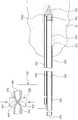
도 3은 본 발명에 따른 생체 검사 시스템에서 프로브 유닛의 구성을 나타낸 사시도이다.
도 4는 본 발명에 따른 생체 검사 시스템에서 니들, 커터, 드라이브 메커니즘, 가이드 튜브와 시료 홀더의 구성을 나타낸 단면도이다.
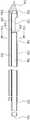
도 5는 본 발명에 따른 생체 검사 시스템에서 니들과 커터의 구성을 나타낸 사시도이다.
도 6는 본 발명에 따른 생체 검사 시스템에서 니들과 커터의 구성을 나타낸 단면도이다.
도 7은 도 6의 Ⅶ-Ⅶ선 확대 단면도이다.
도 8은 본 발명에 따른 생체 검사 시스템에서 니들을 조직에 찔러 넣는 동작을 설명하기 위하여 나타낸 단면도이다.
도 9은 도 8에서 조직이 니들이 통로 안에 흡인되는 동작을 설명하기 위하여 나타낸 단면도이다.
도 10은 도 9에서 조직 시료의 절단 완료 시점 이전에 니들의 통로 안이 대기압으로 조성되는 동작을 설명하기 위하여 나타낸 단면도이다.
도 11은 도 10에서 조직 시료가 커터의 통로로 수송되는 동작을 설명하기 위하여 나타낸 단면도이다.
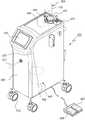
도 12는 본 발명에 따른 생체 검사 시스템에서 컨트롤 유닛의 구성을 나타낸 사시도이다.
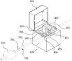
도 13은 본 발명에 따른 생체 검사 시스템에서 솔레노이드 액추에이터의 구성을 나타낸 사시도이다.
도 14는 본 발명에 따른 생체 검사 시스템의 제어를 설명하기 위하여 나타낸 블록도이다.1 is a perspective view illustrating a configuration in which a drive unit and a probe unit are coupled in a biometric test apparatus according to the present invention.
2 is a perspective view illustrating a configuration in which a drive unit and a probe unit are separated from each other in a biometric test system according to the present invention.
3 is a perspective view illustrating a configuration of a probe unit in a biometric inspection system according to the present invention.
4 is a cross-sectional view illustrating the structure of a needle, a cutter, a drive mechanism, a guide tube, and a sample holder in the biometric test system according to the present invention.
5 is a perspective view showing a configuration of a needle and a cutter in the biometric test system according to the present invention.
6 is a cross-sectional view illustrating the structure of a needle and a cutter in a biometric inspection system according to the present invention.
7 is an enlarged cross-sectional view taken along line VII-VII of FIG.
8 is a cross-sectional view illustrating an operation of sticking a needle into a tissue in a biopsy system according to the present invention.
Fig. 9 is a cross-sectional view illustrating the operation in which the tissue is sucked into the passage in Fig. 8; Fig.
FIG. 10 is a cross-sectional view illustrating an operation in which the passage of the needle is formed at atmospheric pressure before the end of cutting of the tissue sample in FIG. 9; FIG.
11 is a cross-sectional view showing the operation of transporting the tissue sample into the path of the cutter in Fig.
12 is a perspective view showing a configuration of a control unit in the biometric inspection system according to the present invention.
13 is a perspective view illustrating the configuration of a solenoid actuator in the biometric test system according to the present invention.
FIG. 14 is a block diagram illustrating control of a biometric inspection system according to the present invention.
본 발명의 그 밖의 목적, 특정한 장점들과 신규한 특징들은 첨부된 도면들과 연관되어지는 이하의 상세한 설명과 바람직한 실시예들로부터 더욱 분명해질 것이다.Other objects, specific advantages and novel features of the present invention will become more apparent from the following detailed description and preferred embodiments with reference to the accompanying drawings.
이하, 본 발명에 따른 생체 검사 장치 및 시스템에 대한 바람직한 실시예들을 첨부된 도면들에 의거하여 상세하게 설명한다.DETAILED DESCRIPTION OF THE PREFERRED EMBODIMENTS Hereinafter, preferred embodiments of a biometric test apparatus and system according to the present invention will be described in detail with reference to the accompanying drawings.
먼저, 도 1과 도 2를 참조하면, 본 발명에 따른 생체 검사 시스템(10)은 생체 검사 장치를 구성하는 드라이브 유닛(Driver unit: 100)과 프로브 유닛(Probe unit: 200)을 구비한다. 드라이브 유닛(100)과 프로브 유닛(200)은 한 벌로 조합되어 조직(20)의 시료를 채취하는데 사용되고, 사용자가 한 손으로 잡고 사용할 수 있도록 구성되어 있다. 조직 시료의 채취 후, 프로브 유닛(200)은 드라이브 유닛(100)과 분리되어 폐기되고, 드라이브 유닛(100)은 새로운 프로브 유닛과 결합되어 재사용된다.Referring first to FIGS. 1 and 2, a
드라이브 유닛(100)은 드라이브 하우징(Drive housing: 110), 전기모터(120), 드라이빙 기어(Driving gear: 130), 애퍼처 버튼(Aperture button: 140)과 커팅 버튼(Cutting button: 142)을 구비한다. 전기모터(120)는 드라이브 하우징(110) 안에 장착되어 있다. 드라이빙 기어(130)는 전기모터(120)의 구동에 의하여 회전할 수 있도록 전기모터(120)의 샤프트(122)에 연결되어 있다. 드라이빙 기어(130)의 하부는 드라이브 하우징(110)의 하면에 돌출되어 있다. 애퍼처 버튼(140)과 커팅 버튼(142) 각각은 드라이브 하우징(110)의 상면 전방에 장착되어 있다. 사용자는 애퍼처 버튼(140)의 조작에 의하여 조직 시료의 채취량을 조절할 수 있다. 사용자는 커팅 버튼(142)의 조작에 의하여 조직의 절단을 실시할 수 있다.The
도 1 내지 도 7을 참조하면, 프로브 유닛(200)은 프로브 하우징(210)과 니들(220)을 구비한다. 프로브 하우징(210)은 드라이브 하우징(110)과 결합 및 분리할 수 있도록 구성되어 있으며, 근위단부(Proximal end: 212)와 원위단부(Distal end: 224)를 갖는다. 니들(220)은 근위단부(222), 원위단부(224), 팁(Tip: 226), 통로(228), 시료 수취 포트(230)와 에어 유입 통로(Air inflow passageway: 232)을 갖는 길이가 긴 중공 튜브(Hollow tube)로 구성되어 있다. 근위단부(222)는 개방되어 있으며, 프로브 하우징(210)의 원위단부(212)에 결합되어 있다. 원위단부(224)는 프로브 하우징(210)의 길이 방향을 따라 연장되어 있고, 팁(226)에 의하여 막혀 있다. 통로(228)는 니들(220)의 내측에 근위단부(222)와 원위단부(224)를 연결하도록 형성되어 있다. 시료 수취 포트(230)는 원위단부(224)와 이웃하는 니들(220)의 상면 외면에 통로(228)와 연통되도록 형성되어 있다. 에어 유입 통로(232)는 니들(220)의 외면 하부에 통로(228)과 구획되도록 니들(220)의 길이 방향을 따라 형성되어 있고, 원위단부(224)에서 통로(228)와 연통되어 있다. 통로(228)와 에어 유입 통로(232)는 팁(226)의 내면에 형성되어 있는 연결 통로(226a)에 의하여 연결되어 있다. 도 6과 도 7에 도시되어 있는 바와 같이, 에어 유입 통로(232)는 길이가 긴 중공 튜브를 니들(220)의 외면 하부에 용접하여 구성되어 있는 것이 도시되어 있다.Referring to FIGS. 1 to 7, the
프로브 유닛(200)의 조직(20)의 절단을 위하여 니들(220)의 통로(228) 안에 회전 및 병진이동할 수 있도록 배치되어 있는 커터(240)를 구비한다. 커터(240)는 근위단부(242), 원위단부(244), 통로(246)와 날끝(Blade edge: 248)을 갖는 길이가 긴 중공 튜브로 구성되어 있다. 근위단부(242)는 개방되어 있으며, 니들(220)의 근위단부(222)를 빠져나와 프로브 하우징(210) 안에 배치되어 있다. 원위단부(244)는 니들(220)의 통로(228) 안에 끼워져 있다. 통로(246)는 커터(240)의 근위단부(242)와 원위단부(244)를 연결하도록 형성되어 있으며, 니들(220)의 통로(228)와 서로 연통되도록 동축으로 배치되어 있다. 날끝(248)은 조직(20)의 절단을 위하여 원위단부(244)에 형성되어 있다.And a
도 2 내지 도 4를 참조하면, 프로브 유닛(200)은 드라이빙 기어(130)와 연동하여 커터(240)를 회전 및 병진이동시키는 드라이브 메커니즘(250)을 구비한다. 드라이브 메커니즘(250)은 리드 스크루(Lead screw: 260), 고정너트(Fixed nut: 270), 커넥팅 튜브(Connecting tube: 280)와 드리븐 기어(Driven gear: 290)로 구성되어 있다. 리드 스크루(260)는 프로브 하우징(210) 안에 회전 및 병진이동할 수 있도록 장착되어 있고, 커터(240)의 근위단부(242)에 결합되어 있다. 리드 스크루(260)는 통로(246)와 연통되는 보어(Bore: 262)를 갖는 중공 튜브로 구성되어 있다. 고정너트(270)는 프로브 하우징(210) 안에 고정되도록 장착되어 있으며, 리드 스크루(260)와 나사 운동할 수 있도록 리드 스크루(260)에 결합되어 있다. 커넥팅 튜브(280)는 프로브 하우징(210) 안에 회전 및 병진이동할 수 있도록 장착되어 있고, 리드 스크루(260)에 결합되어 있다.2 to 4, the
커넥팅 튜브(280)는 리드 스크루(260)의 보어(262)와 연통되는 보어(282)를 갖는 중공 튜브로 구성되어 있다. 슬라이드 튜브(Slide tube: 284)가 프로브 하우징(210)의 근위단부(212)를 향하여 연장되도록 커넥팅 튜브(280)의 보어(282)에 결합되어 있다. 드리븐 기어(290)는 프로브 하우징(210) 안에 제자리에서 회전할 수 있도록 장착되어 있고, 커넥팅 튜브(280)를 회전시킬 수 있도록 커넥팅 튜브(280)의 외면에 장착되어 있다. 드리븐 기어(290)의 외면 상부는 프로브 하우징(210)의 상면에 돌출되어 드라이빙 기어(130)와 맞물린다.The connecting
프로브 유닛(200)은 커넥팅 튜브(280)의 회전 및 병진이동을 안내하는 가이드 튜브(Guide tube: 300)를 구비한다. 가이드 튜브(300)는 근위단부(302), 원위단부(304)와 보어(306)를 가지며, 프로브 하우징(210)에 고정되도록 장착되어 있다. 고정블록(Fixed block: 308)이 가이드 튜브(300)의 외면에 결합되어 있다. 고정블록(308)은 프로브 하우징(310)의 근위단부(312)에 고정되어 있다. 가이드 튜브(300)의 근위단부(302)는 프로브 하우징(210) 밖으로 연장되어 있다. 슬라이드 튜브(284)는 원위단부(304)와 이웃하는 가이드 튜브(300)의 보어(306) 안에 회전 및 병진이동할 수 있도록 끼워져 있다. 가이드 튜브(300)의 보어(306)는 슬라이드 튜브(284)의 보어(286)와 연통되어 있다. 슬라이드 튜브(284)는 가이드 튜브(300)의 보어(306)를 따라 슬라이딩(Sliding)되면서 회전 및 병진이동된다. 리드 스크루(260)의 보어(262), 커넥팅 튜브(280)의 보어(282), 슬라이드 튜브(284)의 보어(286)와 가이드 튜브(300)의 보어(306) 각각은 커터(240)의 통로(246)와 마찬가지로 조직 시료(22)의 수송을 위한 통로로서의 기능을 한다. 몇몇 실시예에 있어서, 커넥팅 튜브(280)는 배제되고, 드리븐 기어(290)는 리드 스크루(260)에 결합될 수 있다. 이 경우, 리드 스크루(260)는 회전 및 병진이동할 수 있도록 가이드 튜브(300)의 보어(306)에 끼워진다. 또한, 슬라이드 튜브(284)는 배제되고, 커넥팅 튜브(280)는 회전 및 병진이동할 수 있도록 가이드 튜브(300)의 보어(306)에 끼워질 수 있다.The
도 1 내지 도 4를 참조하면, 프로브 유닛(200)은 조직 시료(22)의 채취를 위한 시료 홀더(310)를 구비한다. 시료 홀더(310)는 컵(Cup: 320)과 트레이(Tray: 330)로 구성되어 있다. 컵(320)은 프로브 하우징(210)의 근위단부(212)에 분리할 수 있도록 결합되어 있으며, 외부에서 그 안을 관찰할 수 있도록 투명한 플라스틱을 소재로 제작되어 있다. 컵(320)은 개방단부(322)가 형성되어 있는 안쪽 공간(Interior space: 324)과, 안쪽 공간(324)과 연통되도록 외면 하부에 형성되어 있는 에어 유출 포트(Air outflow port: 326)를 갖는다. 트레이(330)는 컵(320)의 안쪽 공간(324)에 여닫을 수 있도록 결합되어 있다. 트레이(330)의 바닥은 조직 시료(22)의 채취 시 발생되는 혈액과 같은 액체를 여과할 수 있는 그릴(Grill: 332)로 형성되어 있다. 조직 시료(22)는 가이드 튜브(300)의 보어(306)를 통과하여 그릴(332) 위에 채집된다.Referring to FIGS. 1 to 4, the
진공 라인(Vacuum line: 340)으로 플렉시블 튜브(Flexible tube: 342)가 에어 유출 포트(326)에 연결되어 있다. 에어 유입 라인(Air inflow line: 350)으로 플렉시블 튜브(352)는 제1 말단(354), 제2 말단(356), 제1 말단(354)과 제2 말단(356)을 연결하도록 형성되어 있는 통로(358)를 갖는다. 제1 말단(354)은 에어 유입 통로(232)에 연결되어 있다. 제2 말단(356)은 공기의 유입을 위하여 대기 중에 노출되어 있다.A
도 8 내지 도 11을 참조하면, 플렉시블 튜브(352)는 제2 말단(356)과 이웃하는 외면에 형성되어 있는 변형 밸브 부분(Deformation valve portion: 360)을 갖는다. 변형 밸브 부분(360)은 외력이 가해지면 납작하게 변형되어 통로(358)를 닫아준다. 외력이 제거되면, 변형되어 있던 변형 밸브 부분(360)이 복원되어 통로(358)를 열어준다. 변형 밸브 부분(360)의 두께는 변형성이 향상되도록 플렉시블 튜브(352)의 다른 부분의 두께보다 얇게 형성되어 있다. 도 1과 도 2에 도시되어 있는 바와 같이, 에어 필터(Air fitter: 370)가 공기의 여과를 위하여 제2 말단(356)에 결합되어 있다. 에어 유입 라인(350)은 에어 유입 통로(232)와 에어 필터(370)를 포함한다.8-11, the
도 12 내지 도 14를 참조하면, 본 발명에 따른 생체 검사 시스템(10)은 드라이브 유닛(100)과 프로브 유닛(200)의 작동을 제어하기 위한 컨트롤 유닛(Control unit: 400)을 구비한다. 컨트롤 유닛(400)은 케이스(410), 컨트롤러(Controller: 420), 터치스크린(Touch screen: 430), 진공원(Vacuum source: 440), 캐니스터(Canister: 450), 진공 풋 스위치(Vacuum foot switch: 460), 에어 풋 스위치(Air foot switch: 462), 솔레노이드 액추에이터(Solenoid actuator: 470)로 구성되어 있다. 케이스(410)는 복수의 캐스터(Caster: 412)에 의하여 이동이 자유롭게 구성되어 있다. 컨트롤러(420)와 진공원(430)은 케이스(410) 안에 장착되어 있다. 컨트롤러(420)는 케이블(422)에 의하여 전기모터(120), 애퍼처 버튼(140), 커팅 버튼(142)과 접속되어 있다. 터치스크린(430)은 사용자가 조작하게 쉽게 케이스(410)의 상면에 장착되어 있다. 진공원(440)은 진공펌프(442), 압력조정기(444), 진공체임버(446)으로 구성되어 있다. 캐니스터(450)는 케이스(410)의 상면에 분리할 수 있도록 결합되어 있다. 진공펌프(442)는 플렉시블 튜브(342)에 의하여 압력조정기(444), 진공체임버(446)과 캐니스터(450)를 거쳐 에어 유출 포트(326)에 연결되어 있다.12 to 14, the
컨트롤러(420)는 애퍼처 버튼(140), 커팅 버튼(142), 터치스크린(430), 진공 풋 스위치(460)와 에어 풋 스위치(462)로부터 입력되는 신호에 따라 전기모터(120), 진공펌프(442)와 솔레노이드 액추에이터(470)의 작동을 제어한다. 터치스크린(430)은 생체 검사 시스템(10)의 작동을 디스플레이하는 액정표시장치(Liquid crystal display)로 구성될 수 있다. 사용자는 진공 풋 스위치(460)의 조작에 의하여 진공펌프(442)의 작동을 제어할 수 있다. 사용자는 에어 풋 스위치(462)의 조작에 의하여 솔레노이드 액추에이터(470)의 작동을 제어할 수 있다.The
솔레노이드 액추에이터(470)는 케이스(410)의 상면에 장착되어 있다. 솔레노이드 액추에이터(470)는 변형 밸브 부분(360)을 여닫을 수 있는 제1 푸시로드(Push rod: 472)를 갖는다. 웨지 팁(Wedge tip: 474)이 변형 밸브 부분(360)을 선접촉(Line contact)으로 눌러주도록 제1 푸시로드(472)의 선단에 형성되어 있다. 솔레노이드 액추에이터(470)는 변형 밸브 부분(360)을 받쳐주도록 제1 푸시로드(472)와 대향되어 있는 제2 푸시로드(476)을 구비한다. 웨지 팁(478)이 제1 푸시로드(472)의 웨지 팁(474)과 한 쌍을 이루어 변형 밸브 부분(360)을 압박할 수 있도록 제2 푸시로드(476)의 상부에 형성되어 있다. 다른 실시예에 있어서, 제2 푸시로드(476)는 변형 밸브 부분(360)을 받쳐주는 서포트 블록(Support block)으로 구성될 수 있다.The
도 13에 명확히 도시되어 있는 바와 같이, 플렉시블 튜브(352)의 고정을 위하여 한 쌍의 훅(Hook: 480, 482)이 제2 푸시로드(476)의 양쪽에 서로 정렬되도록 배치되어 있다. 플렉시블 튜브(352)가 훅(480, 482) 각각에 걸려 고정되면, 변형 밸브 부분(360)이 제2 푸시로드(476) 위에 놓인다. 몇몇 실시예에 있어서, 플렉시블 튜브(352)의 제2 말단(356)은 공기의 흐름을 단속하는 솔레노이드 밸브(Solenoid valve)에 연결될 수 있다. 플렉시블 튜브(352)는 제2 푸시로드(476)을 지나도록 클램프(Clamp)에 의하여 고정시킬 수 있다. 솔레노이드 액추에이터(470)는 힌지(Hinge: 484)를 중심으로 회전되어 제1 푸시로드(472), 제2 푸시로드(476), 훅(480, 482)을 덮어주는 커버(486)를 구비한다.A pair of
지금부터는, 이와 같은 구성을 갖는 본 발명에 따른 생체 검사 장치 및 시스템에 대한 작용을 설명한다.Hereinafter, the operation of the biometric test apparatus and system according to the present invention having such a configuration will be described.
도 4, 도 8, 도 13과 도 14를 참조하면, 커터(240)는 니들(220)의 시료 수취 포트(230)를 닫고 있다. 플렉시블 튜브(350)는 변형 밸브 부분(360)이 제2 푸시로드(476)의 웨지 팁(478) 위에 놓이도록 훅(480, 482) 각각에 걸려 고정되어 있다. 솔레노이드 액추에이터(470)의 작동에 의하여 제1 및 제2 푸시로드(472, 476)가 전진되어 변형 밸브 부분(360)을 눌러주고 있다. 제1 및 제2 푸시로드(472, 476) 각각의 웨지 팁(474, 478)은 변형 밸브 부분(360)을 선접촉에 의하여 압박하여 통로(358)를 닫아준다. 사용자는 시료 수취 포트(230)가 닫혀 있는 상태에서 환자의 병변 부위의 조직(20)에 니들(220)을 찔러 넣어 시료 수취 포트(230)가 도달하게 한다.Referring to FIGS. 4, 8, 13 and 14, the
도 4, 도 9, 도 12와 도 14를 참조하면, 사용자가 애퍼처 버튼(140)을 조작하면, 전기모터(120)가 한쪽 방향, 예를 들면 시계 방향으로 작동된다. 전기모터(120)의 구동력은 드라이빙 기어(130)와 드리븐 기어(290)에 의하여 커넥팅 튜브(280)에 전달되고, 커넥팅 튜브(280), 리드 스크루(260)와 커터(240)가 함께 동일한 속도로 회전된다. 또한, 리드 스크루(260)는 고정너트(270)와의 나사 운동에 의하여 프로브 하우징(210)의 원위단부(214)로부터 근위단부(212)를 향하여 병진이동된다. 커터(240), 커넥팅 튜브(280)와 슬라이드 튜브(284)는 리드 스크루(260)와 함께 병진이동된다. 커터(240)가 후퇴되면서 커터(240)에 의하여 닫혀있던 시료 수취 포트(230)가 열린다.Referring to FIGS. 4, 9, 12 and 14, when the user operates the
도 9에 도시되어 있는 바와 같이, 시료 수취 포트(230)의 개구율(Aperture ratio)에 따라 조직 시료(22)의 채취량이 설정된다. 시료 수치 포트(230)가 개방된 후, 사용자가 진공 풋 스위치(460)를 조작하면, 진공펌프(442)가 작동되어 공기의 흡인력을 발생하게 된다. 공기의 흡인력에 의하여 시료 수취 포트(230) 주위의 조직(20)이 시료 수취 포트(230)를 통하여 통로(228) 안으로 유입된다.As shown in Fig. 9, the amount of the
도 10과 도 11을 참조하면, 사용자가 커팅 버튼(142)을 조작하면, 전기모터(120)가 반시계 방향으로 작동된다. 전기모터(120)의 작동에 의하여 커넥팅 튜브(280), 리드 스크루(260)와 커터(240)가 함께 동일한 속도로 회전됨과 동시에 프로브 하우징(210)의 근위단부(212)로부터 원위단부(214)를 향하여 병진이동된다. 또한, 슬라이드 튜브(284)는 가이드 튜브(300)의 보어(306)를 따라 슬라이딩되면서 회전 및 병진이동된다. 이때, 슬라이드 튜브(284)는 가이드 튜브(300)의 원위단부(304) 밖으로 빠지지 않게 되어 있다. 따라서 커터(240), 리드 스크루(260), 커넥팅 튜브(280)와 슬라이드 튜브(284)가 함께 동일한 속도로 회전 및 병진이동할 수 있다. 커터(240)의 회전 및 병진이동에 의하여 날끝(248)이 통로(228) 안에 유입되어 있는 조직(20)을 절단하여 조직 시료(22)를 채취하게 된다. 조직(20)의 절단이 완료되고, 시료 수취 포트(230)가 커터(240)에 의하여 닫히면, 전기모터(120)는 정지된다.Referring to Figs. 10 and 11, when the user operates the
한편, 커터(240)가 시료 수취 포트(230)를 닫기 전, 즉 조직 시료(22)가 커터(240)에 의하여 완전히 절단되는 절단 완료 시점 전에 사용자가 에어 풋 스위치(462)를 조작하게 되면, 솔레노이드 액추에이터(470)가 작동되어 전진되어 있던 제1 및 제2 푸시로드(472, 476)를 후퇴시키게 된다. 제1 및 제2 푸시로드(472, 476)가 후퇴되면, 제1 및 제2 푸시로드(472, 476)에 의하여 압박되어 있던 변형 밸브 부분(360)이 복원되어 통로(358)를 열어주게 된다. 바람직하기로, 솔레노이드 액추에이터(470)의 작동에 의한 대기압의 조성은 조직 시료(22)의 절단 완료 시점 직전에 실시될 수 있다.On the other hand, when the user operates the
계속해서, 통로(358)가 열리면, 공기가 에어 필터(370)를 거치면서 여과된 후, 통로(358)와 에어 유입 통로(232)를 통하여 팁(226)과 이웃하는 통로(228) 안으로 흘러 대기압을 조정하게 된다. 팁(226) 주위의 통로(228) 안이 대기압으로 조성되면, 조직 시료(22)의 수송 방향 선단(24)과 수송 방향 후단(26) 사이의 압력차가 커지게 된다. 즉, 조직 시료(22)의 수송 방향 선단(24)과 이웃하는 통로(228) 안은 진공펌프(442)의 흡인력에 의하여 진공으로 조성되고, 조직 시료(22)의 수송 방향 후단(26)과 이웃하는 통로(228) 안은 공기의 흐름에 의하여 대기압으로 조성된다. 이와 같이 조직 시료(22)의 수송 방향 선단(24)과 수송 방향 후단(26) 사이의 압력차가 순간적으로 발생되면, 압력차에 의하여 조직 시료(22)의 수송이 원활하게 실시된다. 또한, 커터(240)가 시료 수취 포트(230)를 닫기 이전, 즉 커터(240)의 날끝(248)이 니들(220)의 원위단부(224)와 이웃하는 시료 수취 포트(230)의 내측 단부를 지나치기 전에 통로(228) 안이 대기압으로 조성되어 조직 시료(22)의 절단 및 수송을 보다 원활하게 한다. 몇몇 실시예에 있어서, 대기압의 조성 시점은 커터(240)가 시료 수취 포트(230)의 절반을 닫는 시점부터 완전히 닫는 시점으로 설정할 수 있다.Subsequently, when the
한편, 조직 시료(22)는 진공펌프(442)의 흡인력에 의하여 니들(220)의 원위단부(224)로부터 커터(240)의 근위단부(242)를 향하여 수송된다. 조직 시료(22)는 니들(220)의 통로(228), 커터(240)의 통로(246), 리드 스크루(260)의 보어(262), 커넥팅 튜브(280)의 보어(282), 슬라이드 튜브(284)의 보어(286)와 가이드 튜브(300)의 보어(306) 각각을 통하여 이송되어 트레이(330)에 배출된다. 조직 시료(22)의 채취 시 발생되는 혈액 등의 액체는 그릴(332)에 의하여 여과된 후, 플렉시블 튜브(342)를 통하여 캐니스터(450)에 담겨진다.The
이상에서 설명된 실시예는 본 발명의 바람직한 실시예를 설명한 것에 불과하고, 본 발명의 권리범위는 설명된 실시예에 한정되는 것은 아니며, 본 발명의 기술적 사상과 특허청구범위 내에서 이 분야의 당업자에 의하여 다양한 변경, 변형 또는 치환이 가능할 것이며, 그와 같은 실시예들은 본 발명의 범위에 속하는 것으로 이해되어야 한다.While the present invention has been described in connection with what is presently considered to be practical exemplary embodiments, it is to be understood that the invention is not limited to the disclosed embodiments, but, on the contrary, It will be understood by those skilled in the art that various changes in form and details may be made therein without departing from the spirit and scope of the invention as defined by the appended claims.
20: 조직22: 조직 시료
100: 드라이브 유닛110: 드라이브 하우징
120: 전기모터130: 드라이빙 기어
200: 프로브 유닛210: 프로브 하우징
220: 니들228: 통로
230: 시료 수취 포트232: 에어 유입 통로
240: 커터246: 통로
250: 드라이브 메커니즘260: 리드 스크루
270: 고정너트280: 커넥팅 튜브
290: 드리븐 기어300: 가이드 튜브
310: 시료 홀더320: 컵
330: 트레이340: 진공 라인
342: 플렉시블 튜브350: 에어 유입 라인
352: 플렉시블 튜브360: 변형 밸브 부분
370: 에어 필터380: 컨트롤 유닛
410: 케이스420: 컨트롤러
440: 진공원442: 진공펌프
450: 캐니스터470: 솔레노이드 액추에이터
472: 제1 푸시로드476: 제2 푸시로드
480, 482: 훅486: 커버20: tissue 22: tissue sample
100: drive unit 110: drive housing
120: electric motor 130: driving gear
200: probe unit 210: probe housing
220: Needle 228: Passage
230: sample receiving port 232: air inlet passage
240: cutter 246: passage
250: Drive mechanism 260: Lead screw
270: Fixing nut 280: Connecting tube
290: driven gear 300: guide tube
310: Sample holder 320: Cup
330: Tray 340: Vacuum line
342: Flexible tube 350: Air inflow line
352: Flexible tube 360: Deformation valve part
370: Air filter 380: Control unit
410: Case 420: Controller
440: Vacuum source 442: Vacuum pump
450: Canister 470: Solenoid actuator
472: first push rod 476: second push rod
480, 482: Hook 486: Cover
Claims (14)
Translated fromKorean팁에 의하여 막혀 있는 근위단부와, 원위단부와, 통로와, 상기 조직의 유입을 위하여 상기 원위단부와 이웃하는 외면에 상기 통로와 연통되도록 형성되어 있는 시료 수취 포트를 구비하는 니들과;
상기 니들의 통로에 회전 및 병진이동할 수 있도록 배치되어 있고, 상기 니들의 통로 안에 배치되어 있는 근위단부와, 상기 니들의 통로 밖에 배치되어 있는 원위단부와, 상기 니들의 통로와 연통되어 있는 통로를 구비하는 커터와;
상기 커터를 회전 및 병진이동시키는 드라이브 메커니즘과;
상기 조직 및 상기 조직 시료의 흡인을 위하여 상기 커터의 통로와 연결되어 있는 진공 라인과;
상기 조직 시료의 흡인 시 상기 조직 시료의 수송 방향 후단과 이웃하는 상기 니들의 통로 안을 대기압으로 조성할 수 있도록 상기 니들의 통로와 상기 니들 밖의 대기를 연결하는 통로가 형성되어 있는 플렉시블 튜브를 갖는 에어 유입 라인과;
상기 플렉시블 튜브의 통로를 여닫을 수 있도록 상기 플렉시블 튜브를 선택적으로 압박 및 해제하는 제1 푸시로드를 가지며, 상기 제1 푸시로드의 선단에 상기 플렉시블 튜브를 선접촉에 의하여 압박할 수 있도록 웨지 팁이 형성되어 있는 솔레노이드 액추에이터를 포함하는 생체 검사 장치.A biopsy device for cutting tissue and collecting a tissue sample,
A needle having a proximal end closed by a tip, a distal end, a passage, and a sample receiving port formed to communicate with said passage on an outer surface adjacent to said distal end for introduction of said tissue;
A proximal end disposed in the passageway of the needle, a distal end disposed outside the passageway of the needle, and a passageway communicating with the passageway of the needle ;
A drive mechanism for rotating and translating the cutter;
A vacuum line connected to a passage of the cutter for suctioning the tissue and the tissue sample;
An air inlet having a flexible tube in which a passage connecting the passageway of the needle and the atmosphere outside the needle is formed so as to form atmospheric pressure in the passage of the needle adjacent to the trailing end of the tissue sample in the transport direction of the tissue sample, Line;
And a first push rod for selectively pressing and releasing the flexible tube so as to open and close the passage of the flexible tube. A wedge tip is formed at the tip of the first push rod so as to press the flexible tube by line contact. And a solenoid actuator provided in the body.
상기 에어 유입 라인은 상기 니들의 통로와 구획되도록 상기 니들의 길이 방향을 따라 형성되어 있고, 상기 니들의 원위단부와 이웃하는 상기 니들의 통로와 연통되어 있으며, 상기 플렉시블 튜브가 연결되어 있는 에어 유입 통로와;
상기 플렉시블 튜브의 말단에 공기의 여과를 위하여 결합되어 있는 에어 필터를 더 구비하는 생체 검사 장치.The method according to claim 1,
The air inflow line is formed along the longitudinal direction of the needle so as to be partitioned from the passage of the needle and communicates with the passage of the needle adjacent to the distal end of the needle, Wow;
Further comprising an air filter coupled to the distal end of the flexible tube for air filtration.
상기 니들의 통로와 상기 에어 유입 통로를 연결하도록 상기 팁의 내면에 연결 통로가 형성되어 있는 생체 검사 장치.3. The method of claim 2,
And a connection passage is formed on an inner surface of the tip to connect the passage of the needle and the air inlet passage.
상기 솔레노이드 액추에이터는,
상기 플렉시블 튜브를 지지하도록 상기 제1 푸시로드와 대향되어 있으며, 상기 제1 푸시로드의 웨지 팁과 한 쌍을 이루어 상기 플렉시블 튜브를 압박하는 웨지 팁이 형성되어 있는 제2 푸시로드와;
상기 플렉시블 튜브를 고정할 수 있도록 상기 제2 푸시로드의 양쪽에 서로 정렬되도록 배치되어 있는 한 쌍의 훅을 더 구비하는 생체 검사 장치.The method according to claim 1,
The solenoid actuator includes:
A second push rod opposed to the first push rod to support the flexible tube and having a wedge tip formed in a pair with the wedge tip of the first push rod to press the flexible tube;
And a pair of hooks arranged to be aligned with each other on both sides of the second push rod so as to fix the flexible tube.
상기 제1 푸시로드의 압박에 의하여 변형되어 상기 플렉시블 튜브의 통로의 닫을 수 있도록 상기 플렉시블 튜브의 말단과 이웃하는 외면에 변형 밸브 부분이 형성되어 있는 생체 검사 장치.The method according to any one of claims 1 to 3 and 5,
And a deformed valve portion is formed on an outer surface adjacent to a distal end of the flexible tube so as to be deformed by the compression of the first push rod to close the passage of the flexible tube.
상기 변형 밸브 부분의 두께는 상기 플렉시블 튜브의 두께보다 얇게 형성되어 있는 생체 검사 장치.The method according to claim 6,
And the thickness of the deformed valve portion is formed thinner than the thickness of the flexible tube.
상기 솔레노이드 액추에이터는 상기 커터가 상기 시료 수취 포트를 닫기 전에 상기 플렉시블 튜브의 통로를 열어주도록 구성되어 있는 생체 검사 장치.The method according to any one of claims 1 to 3 and 5,
And the solenoid actuator is configured to open the passage of the flexible tube before the cutter closes the sample receiving port.
상기 드라이브 메커니즘은,
상기 커터의 회전 및 병진이동을 위한 구동력을 제공하는 전기모터와;
상기 전기모터의 구동에 의하여 회전할 수 있도록 상기 전기모터에 연결되어 있는 드라이빙 기어와;
상기 커터와 함께 회전 및 병진이동할 수 있도록 상기 커터의 근위단부에 결합되어 있고, 상기 커터의 통로와 연통되는 보어를 구비하는 리드 스크루와;
상기 리드 스크루와 나사 운동할 수 있도록 결합되어 있고, 상기 리드 스크루의 병진이동을 위하여 고정되어 있는 고정너트와;
상기 리드 스크루와 함께 회전 및 병진이동할 수 있도록 상기 리드 스크루에 결합되어 있으며, 상기 리드 스크루의 보어와 연통되는 보어를 구비하는 커넥팅 튜브와;
상기 커넥팅 튜브의 외면에 상기 드라이빙 기어와 맞물리도록 장착되어 있는 드리븐 기어와;
상기 커넥팅 튜브가 회전 및 병진이동할 수 있도록 끼워지는 보어가 형성되어 있는 가이드 튜브를 포함하는 생체 검사 장치.The method according to claim 1,
The drive mechanism comprises:
An electric motor for providing a driving force for rotating and translating the cutter;
A driving gear connected to the electric motor so as to rotate by driving the electric motor;
A lead screw coupled to a proximal end of the cutter for rotating and translating with the cutter and having a bore communicating with a passage of the cutter;
A fixing nut coupled to the lead screw so as to be able to move in a screwed manner and fixed for translational movement of the lead screw;
A connecting tube coupled to the lead screw so as to rotate and translate together with the lead screw, the connecting tube having a bore communicating with a bore of the lead screw;
A driven gear mounted on an outer surface of the connecting tube so as to be engaged with the driving gear;
And a guide tube in which a bore is formed so that the connecting tube can rotate and translate.
상기 드라이브 메커니즘은,
상기 커넥팅 튜브로부터 연장되도록 상기 커넥팅 튜브에 결합되어 있고 상기 가이드 튜브의 보어에 회전 및 병진이동할 수 있도록 끼워져 있는 슬라이드 튜브를 더 포함하는 생체 검사 장치.10. The method of claim 9,
The drive mechanism comprises:
Further comprising a slide tube coupled to the connecting tube to extend from the connecting tube, the slide tube being rotatably and translationally inserted into the bore of the guide tube.
팁에 의하여 막혀 있는 근위단부와, 원위단부와, 통로와, 상기 조직의 유입을 위하여 상기 원위단부와 이웃하는 외면에 상기 통로와 연통되도록 형성되어 있는 시료 수취 포트를 구비하는 니들과;
상기 니들의 통로에 회전 및 병진이동할 수 있도록 배치되어 있고, 상기 니들의 통로 안에 배치되어 있는 근위단부와, 상기 니들의 통로 밖에 배치되어 있는 원위단부와, 상기 니들의 통로와 연통되어 있는 통로를 구비하는 커터와;
상기 커터를 회전 및 병진이동시키는 드라이브 메커니즘과;
상기 조직 및 상기 조직 시료의 흡인을 위하여 상기 커터의 통로와 진공 라인에 의하여 연결되어 있는 진공원과;
상기 조직 시료의 흡인 시 상기 조직 시료의 수송 방향 후단과 이웃하는 상기 니들의 통로 안을 대기압으로 조성할 수 있도록 상기 니들의 통로와 상기 니들 밖의 대기를 연결하는 통로가 형성되어 있는 플렉시블 튜브를 갖는 에어 유입 라인과;
상기 플렉시블 튜브의 통로를 여닫을 수 있도록 상기 플렉시블 튜브를 선택적으로 압박 및 해제하는 제1 푸시로드를 가지며, 상기 제1 푸시로드의 선단에 상기 플렉시블 튜브를 선접촉에 의하여 압박할 수 있도록 웨지 팁이 형성되어 있는 솔레노이드 액추에이터를 포함하는 생체 검사 시스템.A biopsy system for cutting tissue and collecting a tissue sample,
A needle having a proximal end closed by a tip, a distal end, a passage, and a sample receiving port formed to communicate with said passage on an outer surface adjacent to said distal end for introduction of said tissue;
A proximal end disposed in the passageway of the needle, a distal end disposed outside the passageway of the needle, and a passageway communicating with the passageway of the needle ;
A drive mechanism for rotating and translating the cutter;
A vacuum source connected by a vacuum line to the path of the cutter for suctioning the tissue and the tissue sample;
An air inlet having a flexible tube in which a passage connecting the passageway of the needle and the atmosphere outside the needle is formed so as to form atmospheric pressure in the passage of the needle adjacent to the trailing end of the tissue sample in the transport direction of the tissue sample, Line;
And a first push rod for selectively pressing and releasing the flexible tube so as to open and close the passage of the flexible tube. A wedge tip is formed at the tip of the first push rod so as to press the flexible tube by line contact. A biometric system comprising a solenoid actuator.
상기 제1 푸시로드의 압박에 의하여 변형되어 상기 플렉시블 튜브의 통로를 닫을 수 있도록 상기 플렉시블 튜브의 말단과 이웃하는 외면에 변형 밸브 부분이 형성되어 있는 생체 검사 시스템.12. The method of claim 11,
Wherein a deformable valve portion is formed on an outer surface adjacent to a distal end of the flexible tube so as to be deformed by the compression of the first push rod and to close the passage of the flexible tube.
상기 드라이브 메커니즘은,
상기 커터의 회전 및 병진이동을 위한 구동력을 제공하는 전기모터와;
상기 전기모터의 구동에 의하여 회전할 수 있도록 상기 전기모터에 연결되어 있는 드라이빙 기어와;
상기 커터와 함께 회전 및 병진이동할 수 있도록 상기 커터의 근위단부에 결합되어 있고, 상기 커터의 통로와 연통되는 보어를 구비하는 리드 스크루와;
상기 리드 스크루와 나사 운동할 수 있도록 결합되어 있고, 상기 리드 스크루의 병진이동을 위하여 고정되어 있는 고정너트와;
상기 리드 스크루와 함께 회전 및 병진이동할 수 있도록 상기 리드 스크루에 결합되어 있으며, 상기 리드 스크루의 보어와 연통되는 보어를 구비하는 커넥팅 튜브와;
상기 커넥팅 튜브의 외면에 상기 드라이빙 기어와 맞물리도록 장착되어 있는 드리븐 기어와;
상기 커넥팅 튜브가 회전 및 병진이동할 수 있도록 끼워지는 보어가 형성되어 있는 가이드 튜브를 포함하는 생체 검사 시스템.12. The method of claim 11,
The drive mechanism comprises:
An electric motor for providing a driving force for rotating and translating the cutter;
A driving gear connected to the electric motor so as to rotate by driving the electric motor;
A lead screw coupled to a proximal end of the cutter for rotating and translating with the cutter and having a bore communicating with a passage of the cutter;
A fixing nut coupled to the lead screw so as to be able to move in a screwed manner and fixed for translational movement of the lead screw;
A connecting tube coupled to the lead screw so as to rotate and translate together with the lead screw, the connecting tube having a bore communicating with a bore of the lead screw;
A driven gear mounted on an outer surface of the connecting tube so as to be engaged with the driving gear;
And a guide tube in which a bore is fitted to allow the connecting tube to rotate and translate.
상기 드라이브 메커니즘은,
상기 커넥팅 튜브로부터 연장되도록 상기 커넥팅 튜브에 결합되어 있고 상기 가이드 튜브의 보어에 회전 및 병진이동할 수 있도록 끼워져 있는 슬라이드 튜브를 더 포함하는 생체 검사 시스템.14. The method of claim 13,
The drive mechanism comprises:
Further comprising a slide tube coupled to the connecting tube to extend from the connecting tube, the slide tube being rotatably and translationally inserted into the bore of the guide tube.
Priority Applications (5)
| Application Number | Priority Date | Filing Date | Title |
|---|---|---|---|
| KR1020140043035AKR101649713B1 (en) | 2014-04-10 | 2014-04-10 | Biopsy device and system |
| CN201580019103.5ACN106170256B (en) | 2014-04-10 | 2015-04-10 | Biopsy device and system |
| CN202011281375.1ACN112220501B (en) | 2014-04-10 | 2015-04-10 | Biopsy device and system |
| PCT/KR2015/003621WO2015156639A1 (en) | 2014-04-10 | 2015-04-10 | Biopsy device and system |
| US15/303,450US10792021B2 (en) | 2014-04-10 | 2015-04-10 | Biopsy device and system |
Applications Claiming Priority (1)
| Application Number | Priority Date | Filing Date | Title |
|---|---|---|---|
| KR1020140043035AKR101649713B1 (en) | 2014-04-10 | 2014-04-10 | Biopsy device and system |
Publications (2)
| Publication Number | Publication Date |
|---|---|
| KR20150117501A KR20150117501A (en) | 2015-10-20 |
| KR101649713B1true KR101649713B1 (en) | 2016-08-19 |
Family
ID=54288132
Family Applications (1)
| Application Number | Title | Priority Date | Filing Date |
|---|---|---|---|
| KR1020140043035AActiveKR101649713B1 (en) | 2014-04-10 | 2014-04-10 | Biopsy device and system |
Country Status (4)
| Country | Link |
|---|---|
| US (1) | US10792021B2 (en) |
| KR (1) | KR101649713B1 (en) |
| CN (2) | CN112220501B (en) |
| WO (1) | WO2015156639A1 (en) |
Cited By (1)
| Publication number | Priority date | Publication date | Assignee | Title |
|---|---|---|---|---|
| US12064096B2 (en) | 2020-12-30 | 2024-08-20 | Medical Park Co., Ltd. | Needle guide device for biopsy |
Families Citing this family (15)
| Publication number | Priority date | Publication date | Assignee | Title |
|---|---|---|---|---|
| ITUB20152694A1 (en)* | 2015-07-31 | 2017-01-31 | Pietro Musicco | AUTOMATIC GUN FOR BIOPSY |
| WO2017146343A1 (en)* | 2016-02-25 | 2017-08-31 | 백운 | Needle assembly for biopsy |
| US10342572B2 (en)* | 2016-08-15 | 2019-07-09 | Biosense Webster (Israel) Ltd. | Gear mechanism to drive oscillating shaft |
| TWI611019B (en)* | 2017-02-13 | 2018-01-11 | Scl Biotech Ltd | Tissue fine crushing device and equipment with tissue fine crushing device |
| PL235788B1 (en)* | 2017-11-13 | 2020-10-19 | Gdanski Univ Medyczny | Method and the device for the soft tissue biopsy, preferably the humane tissue |
| EP4278984A3 (en)* | 2018-07-31 | 2024-01-17 | Devicor Medical Products, Inc. | Core needle biopsy device for collecting multiple samples in a single insertion |
| CN109330632B (en)* | 2018-11-09 | 2023-09-29 | 上海导向医疗系统有限公司 | Biopsy rotary cutting device |
| CN109443830A (en)* | 2018-12-26 | 2019-03-08 | 王博 | A kind of detection sampler for tumor of breast |
| KR20200141662A (en) | 2019-06-11 | 2020-12-21 | 백운 | Biopsy system |
| KR102231626B1 (en) | 2019-06-11 | 2021-03-23 | 백운 | Biopsy system |
| KR102279962B1 (en) | 2019-06-11 | 2021-07-20 | 백운 | Biopsy system |
| KR102518523B1 (en)* | 2019-06-18 | 2023-04-06 | 고려대학교 산학협력단 | percutaneous device for removal calcification |
| KR102231633B1 (en) | 2019-06-19 | 2021-03-24 | 운스메디칼 주식회사 | Biopsy system |
| CN111839609B (en)* | 2020-08-24 | 2023-11-24 | 厦门乐呵智慧科技有限公司 | Initiative suction type respiratory tract medical sample collection device |
| KR102757706B1 (en)* | 2023-11-20 | 2025-01-21 | 주식회사 메디칼파크 | Biopsy device |
Citations (1)
| Publication number | Priority date | Publication date | Assignee | Title |
|---|---|---|---|---|
| KR100213463B1 (en)* | 1997-03-31 | 1999-08-02 | 신명철 | Needle for sampling of tissue of living body and method for making of the same and operating device of the same |
Family Cites Families (22)
| Publication number | Priority date | Publication date | Assignee | Title |
|---|---|---|---|---|
| US3833000A (en)* | 1972-06-02 | 1974-09-03 | H Bridgman | Medical aspiration system |
| US5526822A (en) | 1994-03-24 | 1996-06-18 | Biopsys Medical, Inc. | Method and apparatus for automated biopsy and collection of soft tissue |
| US5458112A (en)* | 1994-08-15 | 1995-10-17 | Arrow Precision Products, Inc. | Biliary biopsy device |
| US5769086A (en)* | 1995-12-06 | 1998-06-23 | Biopsys Medical, Inc. | Control system and method for automated biopsy device |
| AU9326498A (en)* | 1997-11-24 | 1999-06-10 | Johnson & Johnson Research Pty. Limited | Biopsy instrument with continuous tissue receiving chamber |
| US6086544A (en) | 1999-03-31 | 2000-07-11 | Ethicon Endo-Surgery, Inc. | Control apparatus for an automated surgical biopsy device |
| US6485436B1 (en) | 2000-08-10 | 2002-11-26 | Csaba Truckai | Pressure-assisted biopsy needle apparatus and technique |
| US8109885B2 (en)* | 2002-03-19 | 2012-02-07 | C. R. Bard, Inc. | Biopsy device for removing tissue specimens using a vacuum |
| US7419472B2 (en) | 2003-09-30 | 2008-09-02 | Ethicon Endo-Surgery, Inc. | Biopsy instrument with internal specimen collection mechanism |
| JP3892438B2 (en) | 2003-12-26 | 2007-03-14 | 株式会社日本メディックス | Heating balloon catheter device and its elastic tube device |
| US7740596B2 (en)* | 2004-09-29 | 2010-06-22 | Ethicon Endo-Surgery, Inc. | Biopsy device with sample storage |
| US7517322B2 (en) | 2005-03-04 | 2009-04-14 | Ethicon Endo-Surgery, Inc. | Biopsy device with variable side aperture |
| EP1932481B1 (en) | 2006-12-13 | 2010-06-30 | Ethicon Endo-Surgery, Inc. | Biopsy system with vacuum control module |
| JP5199348B2 (en)* | 2007-06-19 | 2013-05-15 | アルコン リサーチ, リミテッド | Post-occlusion chamber collapse canceling device for surgical apparatus and method of use thereof |
| US8574167B2 (en)* | 2008-12-16 | 2013-11-05 | Devicor Medical Products, Inc. | Needle for biopsy device |
| US20100152610A1 (en)* | 2008-12-16 | 2010-06-17 | Parihar Shailendra K | Hand Actuated Tetherless Biopsy Device with Pistol Grip |
| US8206316B2 (en)* | 2009-06-12 | 2012-06-26 | Devicor Medical Products, Inc. | Tetherless biopsy device with reusable portion |
| US8491542B2 (en)* | 2011-03-07 | 2013-07-23 | Terumo Cardiovascular Systems Corp. | Light weight tube clamp for medical fluids |
| US9414816B2 (en)* | 2011-06-23 | 2016-08-16 | Devicor Medical Products, Inc. | Introducer for biopsy device |
| WO2013122992A1 (en)* | 2012-02-15 | 2013-08-22 | Devicor Medical Products, Inc. | Biopsy device valve assembly |
| US9669172B2 (en)* | 2012-07-05 | 2017-06-06 | Resmed Limited | Discreet respiratory therapy system |
| KR20140033876A (en)* | 2012-09-11 | 2014-03-19 | 신재숙 | Tissue-separator for endoscope |
- 2014
- 2014-04-10KRKR1020140043035Apatent/KR101649713B1/enactiveActive
- 2015
- 2015-04-10CNCN202011281375.1Apatent/CN112220501B/enactiveActive
- 2015-04-10USUS15/303,450patent/US10792021B2/enactiveActive
- 2015-04-10CNCN201580019103.5Apatent/CN106170256B/enactiveActive
- 2015-04-10WOPCT/KR2015/003621patent/WO2015156639A1/enactiveApplication Filing
Patent Citations (1)
| Publication number | Priority date | Publication date | Assignee | Title |
|---|---|---|---|---|
| KR100213463B1 (en)* | 1997-03-31 | 1999-08-02 | 신명철 | Needle for sampling of tissue of living body and method for making of the same and operating device of the same |
Cited By (1)
| Publication number | Priority date | Publication date | Assignee | Title |
|---|---|---|---|---|
| US12064096B2 (en) | 2020-12-30 | 2024-08-20 | Medical Park Co., Ltd. | Needle guide device for biopsy |
Also Published As
| Publication number | Publication date |
|---|---|
| CN112220501B (en) | 2022-04-22 |
| KR20150117501A (en) | 2015-10-20 |
| CN106170256B (en) | 2021-12-28 |
| WO2015156639A1 (en) | 2015-10-15 |
| US10792021B2 (en) | 2020-10-06 |
| CN112220501A (en) | 2021-01-15 |
| US20170035398A1 (en) | 2017-02-09 |
| CN106170256A (en) | 2016-11-30 |
Similar Documents
| Publication | Publication Date | Title |
|---|---|---|
| KR101649713B1 (en) | Biopsy device and system | |
| EP2382923B1 (en) | Pressure/vaccum actuated biopsy device | |
| US7766845B2 (en) | Disposable lancet and lancing cap combination for increased hygiene | |
| US8277393B2 (en) | Biopsy apparatus | |
| JP4290283B2 (en) | Surgical biopsy device | |
| CN104968282B (en) | device and method for biopsy | |
| CN100508897C (en) | Biopsy device incorporating an adjustable probe sleeve | |
| JP2008529668A (en) | Single motor hand-held biopsy device | |
| US20040049128A1 (en) | Biopsy apparatus | |
| JPH04506010A (en) | Biological sample suction device | |
| US20170181735A1 (en) | Biopsy apparatus including a biopsy device having a sample receiving notch with a tissue anchor | |
| AU2014215465B2 (en) | Vacuum assisted handheld biopsy device | |
| CN109069133A (en) | Bioassay syringe | |
| CN109758188A (en) | A kind of clinical medicine biopsy sampling collection device | |
| CN219289536U (en) | Automatic collection kit for Maimotong biopsy tissue | |
| WO2014091502A1 (en) | Devices and methods for biopsy | |
| KR102231626B1 (en) | Biopsy system | |
| CN114983489A (en) | Sampling device before tumour inspection | |
| US20200405277A1 (en) | Endoscopic ultrasound needle device and method for operating the same | |
| CN221599991U (en) | A tumor sampler for conveniently separating tumors | |
| CN209347092U (en) | A kind of tissue sampling device | |
| CN119112255A (en) | A sampling device and separation method for conveniently separating tumors |
Legal Events
| Date | Code | Title | Description |
|---|---|---|---|
| A201 | Request for examination | ||
| PA0109 | Patent application | St.27 status event code:A-0-1-A10-A12-nap-PA0109 | |
| PA0201 | Request for examination | St.27 status event code:A-1-2-D10-D11-exm-PA0201 | |
| R18-X000 | Changes to party contact information recorded | St.27 status event code:A-3-3-R10-R18-oth-X000 | |
| D13-X000 | Search requested | St.27 status event code:A-1-2-D10-D13-srh-X000 | |
| D14-X000 | Search report completed | St.27 status event code:A-1-2-D10-D14-srh-X000 | |
| N231 | Notification of change of applicant | ||
| PN2301 | Change of applicant | St.27 status event code:A-3-3-R10-R13-asn-PN2301 St.27 status event code:A-3-3-R10-R11-asn-PN2301 | |
| PG1501 | Laying open of application | St.27 status event code:A-1-1-Q10-Q12-nap-PG1501 | |
| E902 | Notification of reason for refusal | ||
| PE0902 | Notice of grounds for rejection | St.27 status event code:A-1-2-D10-D21-exm-PE0902 | |
| E13-X000 | Pre-grant limitation requested | St.27 status event code:A-2-3-E10-E13-lim-X000 | |
| P11-X000 | Amendment of application requested | St.27 status event code:A-2-2-P10-P11-nap-X000 | |
| P13-X000 | Application amended | St.27 status event code:A-2-2-P10-P13-nap-X000 | |
| E701 | Decision to grant or registration of patent right | ||
| PE0701 | Decision of registration | St.27 status event code:A-1-2-D10-D22-exm-PE0701 | |
| PR0701 | Registration of establishment | St.27 status event code:A-2-4-F10-F11-exm-PR0701 | |
| PR1002 | Payment of registration fee | St.27 status event code:A-2-2-U10-U11-oth-PR1002 Fee payment year number:1 | |
| PG1601 | Publication of registration | St.27 status event code:A-4-4-Q10-Q13-nap-PG1601 | |
| R18-X000 | Changes to party contact information recorded | St.27 status event code:A-5-5-R10-R18-oth-X000 | |
| FPAY | Annual fee payment | Payment date:20190807 Year of fee payment:4 | |
| PR1001 | Payment of annual fee | St.27 status event code:A-4-4-U10-U11-oth-PR1001 Fee payment year number:4 | |
| PR1001 | Payment of annual fee | St.27 status event code:A-4-4-U10-U11-oth-PR1001 Fee payment year number:5 | |
| PR1001 | Payment of annual fee | St.27 status event code:A-4-4-U10-U11-oth-PR1001 Fee payment year number:6 | |
| PR1001 | Payment of annual fee | St.27 status event code:A-4-4-U10-U11-oth-PR1001 Fee payment year number:7 | |
| PR1001 | Payment of annual fee | St.27 status event code:A-4-4-U10-U11-oth-PR1001 Fee payment year number:8 | |
| PR1001 | Payment of annual fee | St.27 status event code:A-4-4-U10-U11-oth-PR1001 Fee payment year number:9 | |
| PR1001 | Payment of annual fee | St.27 status event code:A-4-4-U10-U11-oth-PR1001 Fee payment year number:10 |