KR101649603B1 - Apparatus for beauty care using high radio frequency with cross-linked electrodes - Google Patents
Apparatus for beauty care using high radio frequency with cross-linked electrodesDownload PDFInfo
- Publication number
- KR101649603B1 KR101649603B1KR1020140152000AKR20140152000AKR101649603B1KR 101649603 B1KR101649603 B1KR 101649603B1KR 1020140152000 AKR1020140152000 AKR 1020140152000AKR 20140152000 AKR20140152000 AKR 20140152000AKR 101649603 B1KR101649603 B1KR 101649603B1
- Authority
- KR
- South Korea
- Prior art keywords
- electrode
- head
- skin
- positive electrode
- present
- Prior art date
- Legal status (The legal status is an assumption and is not a legal conclusion. Google has not performed a legal analysis and makes no representation as to the accuracy of the status listed.)
- Expired - Fee Related
Links
Images


Classifications
- A—HUMAN NECESSITIES
- A61—MEDICAL OR VETERINARY SCIENCE; HYGIENE
- A61N—ELECTROTHERAPY; MAGNETOTHERAPY; RADIATION THERAPY; ULTRASOUND THERAPY
- A61N1/00—Electrotherapy; Circuits therefor
- A61N1/02—Details
- A61N1/04—Electrodes
- A61N1/06—Electrodes for high-frequency therapy
- A—HUMAN NECESSITIES
- A61—MEDICAL OR VETERINARY SCIENCE; HYGIENE
- A61N—ELECTROTHERAPY; MAGNETOTHERAPY; RADIATION THERAPY; ULTRASOUND THERAPY
- A61N1/00—Electrotherapy; Circuits therefor
- A61N1/02—Details
- A61N1/04—Electrodes
- A61N1/0404—Electrodes for external use
- A—HUMAN NECESSITIES
- A61—MEDICAL OR VETERINARY SCIENCE; HYGIENE
- A61N—ELECTROTHERAPY; MAGNETOTHERAPY; RADIATION THERAPY; ULTRASOUND THERAPY
- A61N1/00—Electrotherapy; Circuits therefor
- A61N1/18—Applying electric currents by contact electrodes
- A61N1/32—Applying electric currents by contact electrodes alternating or intermittent currents
- A61N1/328—Applying electric currents by contact electrodes alternating or intermittent currents for improving the appearance of the skin, e.g. facial toning or wrinkle treatment
- A—HUMAN NECESSITIES
- A61—MEDICAL OR VETERINARY SCIENCE; HYGIENE
- A61N—ELECTROTHERAPY; MAGNETOTHERAPY; RADIATION THERAPY; ULTRASOUND THERAPY
- A61N1/00—Electrotherapy; Circuits therefor
- A61N1/18—Applying electric currents by contact electrodes
- A61N1/32—Applying electric currents by contact electrodes alternating or intermittent currents
- A61N1/36—Applying electric currents by contact electrodes alternating or intermittent currents for stimulation
- A61N1/36014—External stimulators, e.g. with patch electrodes
- A61N1/3603—Control systems
- A—HUMAN NECESSITIES
- A61—MEDICAL OR VETERINARY SCIENCE; HYGIENE
- A61N—ELECTROTHERAPY; MAGNETOTHERAPY; RADIATION THERAPY; ULTRASOUND THERAPY
- A61N1/00—Electrotherapy; Circuits therefor
- A61N1/40—Applying electric fields by inductive or capacitive coupling ; Applying radio-frequency signals
- A61N1/403—Applying electric fields by inductive or capacitive coupling ; Applying radio-frequency signals for thermotherapy, e.g. hyperthermia
Landscapes
- Health & Medical Sciences (AREA)
- Life Sciences & Earth Sciences (AREA)
- Animal Behavior & Ethology (AREA)
- Nuclear Medicine, Radiotherapy & Molecular Imaging (AREA)
- Radiology & Medical Imaging (AREA)
- Biomedical Technology (AREA)
- Engineering & Computer Science (AREA)
- General Health & Medical Sciences (AREA)
- Public Health (AREA)
- Veterinary Medicine (AREA)
- Oral & Maxillofacial Surgery (AREA)
- Plastic & Reconstructive Surgery (AREA)
- Biophysics (AREA)
- Heart & Thoracic Surgery (AREA)
- Electrotherapy Devices (AREA)
Abstract
Translated fromKoreanDescription
Translated fromKorean본 발명은 고주파 전류를 이용하여 피부에 열을 발생시키는 미용장치에 관한 것이다.BACKGROUND OF THE
우리 신체의 최외각을 덮고 있는 기관인 피부는 바깥쪽에서부터 표피, 진피, 및 피하지방층의 세 개의 층으로 구성되어 있다. 콜라겐 섬유와 탄력 섬유와 같은 기질 단백질로 이루어진 진피는 표피 아래에 위치하며, 진피에는 혈관, 신경, 땀샘 등이 있다. 콜라겐 섬유는 피부의 구조와 피부 탄력성 유지에 중요하며 콜라겐의 양이 부족해지거나 손상되면 피부 상태의 이상이 초래되고 늙은 피부처럼 보이게 된다. 탄력섬유는 피부의 탄력을 유지하는 중요 물질로 변성이 오면 피부탄력이 없어지게 된다.The skin, the organ that covers the outermost part of our body, consists of three layers, from the outside to the epidermis, the dermis, and the subcutaneous fat layer. The dermis, composed of matrix proteins such as collagen fibers and elastic fibers, is located beneath the epidermis, and the dermis contains blood vessels, nerves, and sweat glands. Collagen fibers are important in maintaining the structure and elasticity of the skin. When the amount of collagen is insufficient or damaged, it causes abnormalities of the skin and looks like an old skin. The elastic fiber is an important substance that maintains the elasticity of the skin, and when it is denatured, the elasticity of the skin is lost.
피부탄력 감소와 주름 등과 같은 피부노화를 방지하기 위한 다양한 시도가 알려졌다. 그런 시도 중의 하나가 미국특허 US6,702,808호와 같이 고주파 에너지를 이용한 피부 치료방법이다. 그러나, 종래기술에 따른 전극을 이용한 고주파 심부가열은 전극과 피부의 접촉 각도에 따라서 전극과 피부의 접촉이 일정하게 지속되지 않는 경우가 많아 임피던스의 변화가 크므로 안정적인 시술을 하기 어려운 문제가 있었다. 또한, 예기치 않게 전극과 피부의 접촉면적이 매우 작아지면 임피던스가 급격하게 상승하여 표피층의 온도가 급격하게 올라 화상 등의 위험이 발생할 수 있어 문제된다.Various attempts have been made to prevent skin aging such as reduced skin elasticity and wrinkles. One such approach is a method of treating skin using high frequency energy, such as US 6,702,808. However, since the contact between the electrode and the skin is not constantly maintained according to the angle of contact between the electrode and the skin, the high-frequency deep heating using the electrode according to the related art has a problem in that it is difficult to perform stable operation because of a large change in impedance. In addition, if the contact area between the electrode and the skin becomes unexpectedly small, the impedance rises sharply, and the temperature of the skin layer suddenly rises.
본 발명의 발명가는 위와 같은 문제점을 해결하기 위하여 오랫동안 연구 노력한 끝에 본 발명을 완성하게 되었다.The inventor of the present invention has made efforts to solve the above problems for a long time and completed the present invention.
피부에 고주파의 전류를 인가하면 감각 신경 및 운동 신경을 자극하지 않기 때문에 불편감이나 근수축을 동반하지 않고도 조직 내의 특정부위를 가열할 수 있다. 본 발명의 목적은 피부에 균일하고 효율적인 방식으로 고주파 전류를 인가할 수 있는 고주파 미용장치를 제공하는데 있다.Applying a high frequency current to the skin does not stimulate sensory nerves and motor nerves, so it can heat certain areas within the tissue without accompanying discomfort or muscle contraction. It is an object of the present invention to provide a high-frequency cosmetic device capable of applying a high-frequency current to the skin in a uniform and efficient manner.
또한, 본 발명의 또 다른 목적은 피부에 예기치 않은 손상을 주지 않도록 안전한 방식으로 고주파 전류를 인가할 수 있는 고주파 미용장치를 제공하는데 있다.Still another object of the present invention is to provide a high-frequency cosmetic device capable of applying a high-frequency current in a safe manner so as not to cause unexpected damage to the skin.
또한, 본 발명의 또 다른 목적은 피부에 따끔거리는 등 이질감 없이 편안한 방식으로 고주파 전류를 인가할 수 있는 고주파 미용장치를 제공하는데 있다.Another object of the present invention is to provide a high-frequency cosmetic device capable of applying a high-frequency current in a comfortable manner without any unpleasant feeling such as tingling on the skin.
한편, 본 발명의 명시되지 않은 또 다른 목적들은 하기의 상세한 설명 및 그 효과로부터 용이하게 추론할 수 있는 범위 내에서 추가적으로 고려될 것이다.On the other hand, other unspecified purposes of the present invention will be further considered within the scope of the following detailed description and easily deduced from the effects thereof.
위와 같은 목적을 달성하기 위하여, 본 발명에 따른 고주파 미용장치는 심부열 발생을 위해 소정의 면적을 갖는 전극면을 피부에 접촉하여 고주파 전류를 인가하는 전극 쌍으로서, 제 1 양전극, 상기 제 1 양전극과 마주하는 제 2 양전극, 상기 제 1 양전극 및 제 2 양전극 사이의 일측에 형성되는 제 1 음전극, 상기 제 1 양전극 및 제 2 양전극 사이의 타측에 형성되는 제 2 음전극을 포함하는 헤드 전극;In order to accomplish the above object, a high frequency cosmetic device according to the present invention is an electrode pair for applying a high-frequency current by bringing an electrode surface having a predetermined area into contact with skin to generate deep heat, the electrode pair including a first positive electrode, A head electrode including a first negative electrode formed on one side between the first positive electrode and the second positive electrode, and a second negative electrode formed on the other side between the first positive electrode and the second positive electrode;
상기 전극 쌍을 양극과 음극으로 교번하여 수납, 고정하는 헤드 플레이트; 및A head plate for alternately storing and fixing the electrode pairs as an anode and a cathode; And
상기 헤드 전극에 고주파 전류를 제공하는 전장부를 포함하는 본체를 포함한다.And a body including an electric field portion for providing a high-frequency current to the head electrode.
또한, 본 발명의 바람직한 어느 실시예에 따른 고주파 미용장치에 있어서, 상기 헤드 전극은 ABS 수지(Acrylonitrile, Butadiene, Styrene resin)로형성된 전극면과 상기 전극면 아래에서 길게 연장되는 지지대를 포함하고, 상기 전극면은 피부에 접촉하는 부분이 도전성 금속으로 도금되어 있는 것을 특징으로 한다.In the high frequency cosmetic device according to the preferred embodiment of the present invention, the head electrode includes an electrode surface formed of ABS resin (acrylonitrile, butadiene, styrene resin) and a support member extending long below the electrode surface, And the electrode surface is characterized in that a portion contacting the skin is plated with a conductive metal.
또한, 본 발명의 바람직한 어느 실시예에 따른 고주파 미용장치에 있어서, 상기 헤드 플레이트는 4 개의 부채꼴 모양의 전극을 각각 양극과 음극으로 교번하여 방사형으로 수납하는 고정 홈을 포함하는 것을 특징으로 한다.Further, in the high-frequency cosmetic device according to the preferred embodiment of the present invention, the head plate includes a fixing groove for alternately storing four radial electrodes into an anode and a cathode in radial form.
또한, 본 발명의 바람직한 어느 실시예에 따른 고주파 미용장치에 있어서, 상기 전장부는 소비전력이 사전에 설정된 소비전력 상한 이하가 되도록 상기 고주파 미용장치의 출력을 제어하는 것을 특징으로 한다.In the high-frequency cosmetic device according to any one of the preferred embodiments of the present invention, the electric-power unit controls the output of the high-frequency cosmetic device so that the power consumption is equal to or lower than a predetermined power consumption upper limit.
또한, 본 발명의 바람직한 어느 실시예에 따른 고주파 미용장치에 있어서, 상기 전장부는 상기 헤드 전극에 인가되는 고주파 전류를 사전에 설정된 안전 듀티 주기에 따라 온오프 제어하는 것을 특징으로 한다.In the high frequency cosmetic device according to any one of the preferred embodiments of the present invention, the electric field unit controls on / off the high-frequency current applied to the head electrode according to a predetermined safety duty cycle.
또한, 본 발명의 바람직한 어느 실시예에 따른 고주파 미용장치에 있어서, 상기 전장부는 상기 헤드 전극의 온도가 사전에 설정된 안전 온도 이하가 되도록 상기 고주파 미용장치의 출력을 제어하는 것을 특징으로 한다.In the high frequency cosmetic device according to any one of the preferred embodiments of the present invention, the electric field part controls the output of the high frequency cosmetic device so that the temperature of the head electrode is equal to or lower than a preset safe temperature.
또한, 본 발명의 바람직한 어느 실시예에 따른 고주파 미용장치에 있어서, 상기 전장부는 상기 헤드 전극이 피부에 접촉한 후 사전에 설정된 휴지 시간이 경과된 후부터 상기 헤드 전극에 고주파 전류를 출력하는 것을 특징으로 한다.In the high frequency cosmetic device according to any one of the preferred embodiments of the present invention, the electric field part outputs a high-frequency current to the head electrode after a predetermined dwell time has elapsed after the head electrode contacts the skin do.
본 발명에 따르면 피부에 인가되는 고주파 전류로 인해 발생하는 심부열이 콜라겐 작용을 증대하여 눈가 주름, 피부 탄력, 피부 리프팅, 진피 치밀도 등을 개선하므로 피부노화를 완화하고, 혈행을 개선하며 손상 피부 회복에 도움을 주는 효과가 있다.According to the present invention, the deep heat generated due to the high frequency current applied to the skin increases the collagen action to improve the wrinkles in the eyes, the skin elasticity, the skin lifting and the density of the dermis so as to alleviate aging of the skin, It has the effect of helping recovery.
종래에는 고주파 심부가열 시 예기치않은 고온발생으로 인해 피부가 손상되는 문제가 있었다. 그러나 본 발명에 따르면 넓은 접촉면을 갖는 방사형의 전극을 복수 쌍으로 사용하므로 피부와 전극의 임피던스 매칭을 용이하게 할 수 있으므로 일정한 온도로 피부를 가열할 수 있는 효과가 있다.Conventionally, there has been a problem that the skin is damaged due to unexpected high temperature generation when the high frequency deep portion is heated. However, according to the present invention, since a plurality of pairs of radial electrodes having a wide contact surface are used, it is possible to easily match the impedance between the skin and the electrodes, thereby heating the skin at a constant temperature.
또한, 본 발명에 따르면, 과도한 열 발생으로인한 피부손상을 방지하기 위해 적어도 삼중의 안전장치를 사용하므로 안전성을 더욱 개선할 수 있다. 삼중의 안전장치는 우선 안전 소비전류 제한, 온/오프 주기 설정/ 안전 온도 제한을 포함한다.In addition, according to the present invention, at least three safeguards are used to prevent skin damage due to excessive heat generation, thereby further improving safety. Triple safety devices include safety current limit first, on / off period setting / safety temperature limit.
또한, 본 발명에 따르면, 전극과 피부 접촉시 소정의 휴지 시간동안 동작을 딜레이 시켜 엣지 전류(edge current)로 인한 피부 따끔거림을 방지하므로 이질감을 감소시킬 수 있는 효과가 있다.In addition, according to the present invention, it is possible to reduce the sense of heterogeneity by preventing the skin tingling due to the edge current by delaying the operation for a predetermined pause time when the skin contacts the electrode.
한편, 여기에서 명시적으로 언급되지 않은 효과라 하더라도, 본 발명의 기술적 특징에 의해 기대되는 이하의 명세서에서 기재된 효과 및 그 잠정적인 효과는 본 발명의 명세서에 기재된 것과 같이 취급됨을 첨언한다.On the other hand, even if the effects are not explicitly mentioned here, the effect described in the following specification, which is expected by the technical features of the present invention, and its potential effects are treated as described in the specification of the present invention.
도 1은 본 발명의 바람직한 일 실시예에 따른 고주파 미용장치의 외부 구성을 나타내는 도면이다.
도 2는 본 발명의 바람직한 일 실시예에 따른 고주파 미용장치의 개략적인 분해 사시도이다.
도 3은 본 발명을 구성하는 헤드부의 바람직한 실시예를 나타내는 도면이다.
도 4는 본 발명을 구성하는 헤드부의 헤드 전극 배치에 대한 바람직한 실시예를 나타내는 도면이다.
도 5는 본 발명을 구성하는 헤드 전극의 구성에 대한 바람직한 실시예를 나타내는 도면이다.
도 6은 본 발명의 전장부 회로 구성의 바람직한 실시예를 개략적으로 나타내는 도면이다.
도 7은 본 발명의 변압기와 주변 회로 구성의 바람직한 실시예를 나타내는 회로도이다.
※ 첨부된 도면은 본 발명의 기술사상에 대한 이해를 위하여 참조로서 예시된 것임을 밝히며, 그것에 의해 본 발명의 권리범위가 제한되지는 아니한다.1 is a diagram showing an external configuration of a high-frequency cosmetic device according to a preferred embodiment of the present invention.
2 is a schematic exploded perspective view of a high-frequency cosmetic device according to a preferred embodiment of the present invention.
Fig. 3 is a view showing a preferred embodiment of the head part constituting the present invention. Fig.
4 is a view showing a preferred embodiment of the head electrode arrangement of the head portion constituting the present invention.
5 is a view showing a preferred embodiment of the structure of the head electrode constituting the present invention.
Fig. 6 is a diagram schematically showing a preferred embodiment of the overall circuit configuration of the present invention.
7 is a circuit diagram showing a preferred embodiment of a transformer and a peripheral circuit configuration of the present invention.
* The accompanying drawings illustrate examples of the present invention in order to facilitate understanding of the technical idea of the present invention, and thus the scope of the present invention is not limited thereto.
이하, 첨부된 도면을 참조하여 본 발명의 실시를 위한 구체적인 내용을 설명한다. 그리고 본 발명을 설명함에 있어서 관련된 공지기능에 대하여 이 분야의 기술자에게 자명한 사항으로서 본 발명의 요지를 불필요하게 흐릴 수 있다고 판단되는 경우에는 그 상세한 설명을 생략한다.Hereinafter, embodiments of the present invention will be described in detail with reference to the accompanying drawings. In the following description of the present invention, a detailed description of known functions and configurations incorporated herein will be omitted when it may obscure the subject matter of the present invention.
본 발명의 고주파 미용장치는 고주파 전류를 통한 전기 자극을 피부에 전달하여 심부열을 발생시키는 장치이다. 피부 미용의 용도로 사용될 수 있으며, 얼굴에 겔을 도포하고 그 위에 본 발명의 미용장치를 사용함으로써 피부노화 완화, 혈행개선, 손상 피부 회복의 효과를 볼 수 있다.The high frequency cosmetic device of the present invention is an apparatus that generates electric heat of the deep portion by transmitting electrical stimulation through high frequency current to skin. It can be used as a skin cosmetic application. By applying the gel to the face and using the beauty device of the present invention, the skin aging can be alleviated, blood circulation can be improved, and damaged skin can be recovered.
고주파 전류(High Frequency Current, HFC)는 100,000 Hz이상의 교류전류를 의미 한다. 고주파 전류는 진동폭(oscillation impulse)이 매우 짧기 때문에 인체조직을 통과할 때 이온운동이 거의 일어나지 않으며 전기화학적 반응(electrochemical reaction)과 전기분해 현상(electrorolytic reaction)이 없다.High Frequency Current (HFC) means an alternating current of 100,000 Hz or more. Since the oscillation impulse is very short, the high frequency current has almost no ionic motion when passing through human tissue, and there is no electrochemical reaction or electrorolytic reaction.
고주파 전류는 매우 빠른 진동주기를 갖고 있는데, 이로 인해 고주파 전류가 지나가는 경로 상에서 전기 에너지가 열 에너지로 변환되는 특징이 있다. 따라서, 고주파 전류를 신체조직에 인가하면 신체조직 안의 특정부위를 가열할 수 있다. 고주파 전류는 신체에 인가되더라도 불편감을 유발하거나 근수축을 일으키지 않는다. 정상근을 자극시킬 수 있는 맥동기간(pulse duration)은 1 ms정도인 반면에 고주파 전류의 맥동기간은 0.001 ms에 지나지 않아 고주파 전류가 인체조직에 인가되더라도 감각신경 및 운동신경을 자극하지 않기 때문이다.High-frequency currents have a very fast oscillation period, which is the characteristic that electric energy is converted into thermal energy on the path of high-frequency current. Thus, applying a high-frequency current to body tissue can heat certain parts of the body tissue. High-frequency currents do not cause discomfort or cause muscle contractions even when applied to the body. The pulse duration that can stimulate the normal muscles is about 1 ms, whereas the pulse period of the high-frequency current is only 0.001 ms, so that even when the high-frequency current is applied to the human tissue, it does not stimulate the sensory nerve and motor nerve.
이와같은 원리를 이용하여, 고주파 전류를 신체에 인가하여 발생하는 열로 신체조직을 치료하는 것을 심부투열치료(diathermy)라 하는데 'diathermy'는 '통하다(through)'라는 뜻을 가진 'dia'라는 말과 '열(heat)'이라는 뜻을 가진 'therm'이라는 두단어를 합성한 말로, 열을 피부를 통하여 신체조직 속으로 투과시킨다는 뜻이며 흔히 심부투열 또는 심부가열(deep heating)이라 한다.Using this principle, treating the body tissue with the heat generated by applying a high frequency current to the body is called diathermy, while 'diathermy' is called 'dia' which means 'through' And 'therm', which means 'heat', means to penetrate heat through the skin into the body tissues and is often referred to as deep deep heat or deep heating.
주파수가 낮을수록 피부 깊이 침투하며 매질의 수분 함량이 적을수록 침투깊이가 깊은 특징이 있다. 따라서, 300khz와 500khz대의 주파수는 피하지방의 제거를 위해 사용되고, 1Mhz 내지 2Mhz의 주파수가 피부 미용에 사용된다. 본 발명의 고주파 미용장치는 소비전력, 자기장, 열감, 임상평가를 고려하여 1Mhz의 주파수를 사용하지만 반드시 이에 한정되는 것은 아니다.
The lower the frequency, the more penetrating the skin, and the lower the water content of the medium, the more penetrating depth. Therefore, frequencies of 300kHz and 500kHz are used for the removal of subcutaneous fat, and frequencies of 1Mhz to 2Mhz are used in skin cosmetics. The high frequency cosmetic device of the present invention uses a frequency of 1 MHz in consideration of power consumption, magnetic field, heat sensation, clinical evaluation, but is not limited thereto.
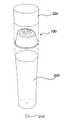
도 1은 본 발명의 바람직한 일 실시예에 따른 고주파 미용장치(1)의 외부 구성을, 도 2는 도 1의 분리 사시도를 나타낸다. 도 1 및 도 2에서 알 수 있듯이, 고주파 미용장치(1)는 헤드부(100) 및 본체(200)로 구성된다.Fig. 1 shows an external configuration of a high-frequency
헤드부(100)는 본체(200)와 나사식 결합을 하거나 혹은 슬라이딩 방식으로 착탈 가능하게 구성될 수 있다. 헤드부(100)는 헤드 전극(110), 헤드 플레이트(120), 및 헤드 커버(130)를 포함한다. 헤드 전극(110)은 피부에 접촉하여 심부열 발생을 위한 고주파 전류를 인가하는 전극이다. 적어도 둘 이상의 전극 쌍(적어도 넷 이상의 전극)을 포함하며, 피부에 접촉되는 부분이 면이 될 수 있도록 넓적한 형상이다. 헤드 플레이트(120)는 헤드 전극(110)을 수납하고 고정한다. 헤드 커버(130)는 헤드부(100)의 외부 형태를 형성한다. 헤드 커버(130)의 상면에는 헤드 전극(110)이 수납된 헤드 플레이트(120)가 비스듬하게 결합될 수 있다.The
본체(200)는 케이스 기능을 하며, 스위치(210)와 커버(220)를 포함한다. 스위치(210)는 본체(200)의 바닥면에 형성될 수 있다. 도시하지 않았지만, 본체(200)의 바닥쪽(헤부(100)의 반대쪽 단부)에는 충전단자가 설치되어 내부의 회로와 전기적으로 연결될 수 있다. 바람직하게는 스위치(210)는 LED 소자가 일체로 결합될 수 있다. 또한, 충전 단자를 보호하기 위해서 고무 재질의 베이스 커버가 본체(200)의 바닥에 결합될 수 있다.The
바람직한 실시예에 있어서 스위치(210)는 한 번 누를 때마다 '파워 약', '파워 강', 및 '전원 오프' 모드로 전환되며 동작할 수 있고, 스위치에 포함된 LED 소자를 통해서 충전 상태를 표시할 수 있다. LED 소자는 충전 중 '적색', 완충 시 '초록색'으로 표시되고, 충전이 필요할 때 '적색 점멸'로 동작할 수 있다. 커버(220)는 헤드부(100)를 덮는 형태로 본체(200)의 일단에 결합되어 헤드부(100)를 보호한다.In a preferred embodiment, the
본체(200)의 내부에는, 도시되어 있지는 않지만, 헤드부(100)에 고주파 전류를 공급하는 전장부가 내장되어 있다. 일 실시예에 있어서 본체(200)는 전면 케이스, 후면 케이스가 결합하여 원통형의 몸체를 형성할 수 있고, 내부에는 전장부를 결합하기 위한 나사홈, 배터리를 고정하는 배터리 홀더가 포함될 수 있다. 다만, 전장부의 회로 구성에 대한 자세한 설명은 도 6 및 도 7과 함께 후술한다.
Inside the
이하, 헤드부(100)의 바람직한 실시예에 대해서 도면을 참고하여 보다 상세하게 설명한다.Hereinafter, a preferred embodiment of the
도 3은 헤드부(100)의 바람직한 실시예를 나타내는 분해 사시도이고, 도 4는 헤드부(100)의 헤드 전극(110) 배치에 대한 바람직한 실시예를 나타내는 평면도이다.Fig. 3 is an exploded perspective view showing a preferred embodiment of the
도 3에서 알 수 있듯이, 헤드부(100)는 고주파전류를 피부에 인가하는 헤드 전극(110), 헤드 전극(110)을 수납, 고정하는 헤드 플레이트(120), 및 헤드 플레이트(120)와 결합하는 헤드 커버(130)를 포함한다.3, the
바람직한 실시예에 있어서, 헤드 전극(110)은 제 1 양전극(111), 제 1 음전극(113), 제 2 양전극(115), 및 제 2 음전극(117)을 포함할 수 있다. 네 개의 전극은 각각 넓적한 형상의 전극면과 전극면 하단에서 길게 연장된 지지대를 포함한다. 지지대는 헤드 플레이트(120)의 관통홀(121)을 통과하며, 전극면의 하면은 헤드 플레이트(120)의 고정 홈(123)에 끼워맞춰 고정된다. 바람직한 실시예에 있어서 두 개의 양전극(111, 115)에 형성된 지지대의 길이가 두 개의 음전극(113, 117)에 형성된 지지대의 길이보다 길게 형성될 수 있다. 길게 형성된 지지대는 본체와 전극을 지지하고, 짧게 형성된 지지대는 전장부와 전극을 지지할 수 있다.In a preferred embodiment, the
헤드 플레이트(120)는 헤드 커버(130)의 상부에 결합되는데, 이때 헤드 플레이트(120)는 헤드 커버(130)의 상면과 소정의 각도를 형성하며 기울어진 모양으로 결합될 수 있다. 이와 같이, 헤드 플레이트(120)가 기울어져 있는 경우 사용자는 보다 편리하게 고주파 미용장치를 사용할 수 있다.The
한편, 도 4에서 알 수 있듯이, 네 개의 전극은 각각 부채꼴 모양일 수 있으며, 헤드 플레이트의 중심을 기점으로 방사형으로 배치될 수 있다. 이때 전극은 양극과 음극이 교번하여 배치된다. 예를 들면, 제 1 양전극(111) 옆에는 음전극인 제 1 음전극(113)이 배치되고, 그 옆에는 양전극인 제 2 양전극(115)이 배치되고, 그 옆에는 다시 음전극인 제 2 음전극(117)이 배치된다. 이와 같이 양극과 음극이 교번하여 배치되면, 보다 넓은 영역의 피부에 심부열을 발생시킬 수 있는 효과가 있다.Meanwhile, as shown in FIG. 4, the four electrodes may be in the shape of a sector, and may be arranged radially from the center of the head plate. At this time, the positive electrode and the negative electrode are arranged alternately. For example, a first
이상의 실시예에서 헤드 전극(110)은 네 개의 전극을 포함하는 것으로 설명하였지만, 본 발명의 고주파 미용장치가 반드시 이에 한정되는 것은 아니고 더 많은 전극을 포함할 수 있다. 또한, 전극면의 모양은 부채꼴 이외에도 삼각형, 마름모와 같이 변형될 수 있다.Although the
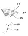
도 5는 본 발명을 구성하는 헤드 전극의 구성에 대한 바람직한 실시예를 나타내는 도면이다.5 is a view showing a preferred embodiment of the structure of the head electrode constituting the present invention.
도 5에서 알 수 있듯이, 일 실시예에 있어서 헤드 전극은 전극면(310), 전극면(310)의 하면 일부영역에서 아래로 돌출되어 형성된 전극 지지부(320), 전극 지지부(320)의 하면 일부 영역에서 아래로 길게 연장되어 형성된 지지대(330), 전극면(310)의 상면에 도금되어 형성된 도금면(340), 및 도금면(340)과 전기적으로 연통된 연결도선(350)을 포함할 수 있다. 헤드 전극은 도금 가능한 ABS 수지(Acrylonitrile, Butadiene, Styrene resin)로 형성될 수 있고, 도금면(340)은 백금일 수 있다. 도금면(340)의 도금 두께는 0.2um일 수 있으나 반드시 이에 한정되는 것은 아니다. 연결도선(350)은 지지대(330) 내부를 관통하여 내려올 수 있다. 다른 실시예에서 헤드 전극의 외부면이 모두 도금될 수 있다. 이 경우에는 연결도선(350)이 별도로 필요하지 않을 수 있다.5, the head electrode includes an
일 실시예에 있어서, 헤드 전극을 헤드 플레이트에 조립할 때, 지지대(330)는 관통홀(도 3의 121)을 통과하고, 전극 지지부(320)는 관통홀(121)에 끼워맞춰지며, 전극면(310)은 고정 홈(도 3의 123)에 끼워맞춰질 수 있다. 조립 후 이를 위에서 내려다 본 평면도는 도 4와 같은데, 이때 헤드 전극에서 외부로 노출되는 것은 피부에 접촉하는 도금면(340)이고, 나머지 구성들은 헤드 플레이트와 헤드 커버 안쪽에 위치한다.In one embodiment, when assembling the head electrode to the head plate, the
도 6은 본 발명의 전장부 회로 구성의 바람직한 실시예를 개략적으로 나타내는 도면이다.Fig. 6 is a diagram schematically showing a preferred embodiment of the overall circuit configuration of the present invention.
도 6에서 알 수 있듯이, 본 발명의 전장부는 배터리(410), 충전제어부(415), 승압부(420), 변압기(430), 헤드(440), 중앙처리부(450), 전압제어부(460), 주파수발생부(470), 스위칭부(480), 전류검출부(490), 온도검출부(495)를 포함한다.6, the electrical part of the present invention includes a
본 발명은 USB 충전단자를 통해서 내장된 배터리(410)를 충전할 수 있다. 충전제어부(415)는 충전용 USB 케이블과 배터리(410) 사이에 연결되어 배터리(410)의 충전을 제어한다. 이와 같은 충전 구조 및 방식 이외에 다양한 변형이 가능하다. 본 발명의 다른 변형예로는 건전지 혹은 충전용 건전지를 사용할 수 있다. 또한 본 발명의 바람직한 변형예에서는 USB 충전단자가 아닌 구조의 충전단자를 가질 수 있다. 본 발명의 또 다른 바람직한 변형예에서는 무접점 충전기술을 사용할 수 있다. 이런 변형예에서는 고주파 미용장치의 바닥 부분에는 코일 코어가 설치될 것이다. 어댑터 측 코일에 전류가 흐를 때 발생하는 유도 자기장이 상기 코일 코어에 전류를 발생시킴으로써 배터리(410)를 충전할 수 있다.The present invention can charge the built-in
바람직한 실시예에서 배터리(410)는 3.5V 전압으로 1.25A 이상의 전류를 공급하므로 공급전력은 대략 4.4W이다. 배터리(410) 전압은 승압부(420)의 직류/직류 컨버터에 의해서 대략 10.6V까지 승압된다. 승압된 전압은 변압기(430)의 1차 코일에 인가된다. 변압기(430)의 2차 코일의 전압은 대략 170 내지 200Vpp까지 증폭되며, 증폭된 고주파 전압은 헤드(440) 측의 전극으로 전달된다.In a preferred embodiment, the
전압제어부(460)는 주파수발생부(470)에 공급되는 전원을 제어하며, 온/오프가 가능한 전압 레귤레이터(voltage regulator)로 구성된다. 전압제어부(460)로부터 전압이 공급되면 주파수발생부(470)는 예를 들어 40kHz 내지 4MHz까지 가변 가능한 오실레이터(osaillator)를 사용하여 고주파를 발생시킨다. 바람직한 실시예에서 주파수발생부(470)는 2MHz의 고주파를 스위칭부(480)에 포함된 트랜지스터의 게이트에 인가할 수 있다. 스위칭부(480)는 예를 들면 스위칭 속도가 빠른 MOSFET을 이용하여 주파수발생부(470)에서 입력된 고주파 신호를 변압기(430)에 전달한다.The
전류검출부(490) 헤드 전극의 출력 전류를 측정하여 중앙처리부(450)에 전달한다. 출력 전류를 검출하기 위해서 저항(registor)에 의한 커플링(coupling)을 이용한다. 온도검출부(495)는 헤드 전극의 온도를 측정하여 중앙처리부(450)에 전달한다. 온도검출부(495)는 서미스터(themister)를 이용하여 온도를 측정한다.The
중앙처리부(450)는 MCU(micro controller unit)을 이용한 제어부이며, 배터리의 충방전제어, 승압부의 출력전압제어, 전압제어부의 듀티비제어, 온도 및 전류 검출 등을 실행한다.The
고주파 미용장치가 피부와 접촉하지 않은 경우 부하의 임피던스가 작지만 피부에 접촉하는 경우에는 임피던스가 커지게 되어 출력전압이 커진다. 피부 접촉부위가 이동할 때마다 임피던스가 변동하며, 결과적으로 출력 전력이 일정하지 않게 된다. 이러한 문제를 해결하기 위해 본 발명의 중앙처리부(450)는 다음과 같은 방식으로 헤드 전극의 출력 전류를 일정하게 제어할 수 있다.When the high-frequency cosmetic device is not in contact with the skin, the impedance of the load is small, but when the skin is in contact with the skin, the impedance becomes large and the output voltage becomes large. The impedance changes every time the skin contact portion moves, and as a result, the output power becomes unstable. In order to solve such a problem, the
우선, 전류검출부(490)에서 입력된 전류값을 기준 전류값과 비교한다. 입력된 전류값이 기준 전류값 보다 크면 승압부(420)의 출력전압을 제어하여 전류량을 감소시킨다. 입력된 전류값이 기준 전류값 보다 작으면 승압부(420)의 출력전압을 제어하여 전류량을 증가시킨다. 이와 같은 방법으로 정전류가 출력될 수 있도록 제어한다. 다른 방법으로, 전류검출부(490)에서 입력된 전류값이 기준 전류 이상인 경우 전압제어부(460)를 제어하여 과전류가 흐르지 않도록한다. 입력된 전류값이 기준 전류 미만으로 저하되면 전압제어부(460)의 출력 전압을 정상 전압으로 복귀하여 과전류에 의한 피부 손상을 방지한다.First, the current value input from the
한편, 본 발명의 고주파 미용장치는 피부에 직접 접촉하여 열을 발생시키기 때문에 화상 방지를 위한 안전제어가 중요하다. 이를 위해 본 발명의 중앙처리부(450)는 다음과 같은 적어도 세가지 이상의 안전제어를 동시에 실행할 수 있다.On the other hand, since the high-frequency cosmetic device of the present invention directly contacts the skin to generate heat, safety control for preventing the burn is important. To this end, the
우선, 중앙처리부(450)는 소비전력의 상한을 설정하고, 소비전력이 사전에 설정된 소비전력 상한 이하가 되도록 고주파 미용장치의 출력을 제어할 수 있다. 소비전력 상한을 설정함에 따라 전극의 온도가 지나치게 올라가는 것을 방지할 수 있으며, 배터리의 사용시간을 연장할 수도 있다. 바람직한 실시예에 있어서 소비전력의 상한은 3A일 수 있다. 중앙처리부(450)는 출력을 제어하기 위해 승압부(420)의 출력전압을 제어하거나 전압제어부(460)를 제어할 수 있다.First, the
중앙처리부(450)는 헤드 전극에 인가되는 고주파 전류를 사전에 설정된 안전 듀티 주기에 따라 온오프 제어한다. 이를 위해 중앙처리부(450)는 스위칭부(480)의 MOSFET의 게이트 전극를 온/오프 제어할 수 있다. 바람직한 실시예에 있어서, 안전 듀티 주기는 7초를 주기로 on 5초, off 2초로 구성될 수 있으나 반드시 이에 한정되는 것은 아니다. 다른 실시예에 있어서 5초를 주기로 on 3초, off 2초로 구성될 수 있다. 이와 같이 소정의 시간 동안 고주파 미용장치의 출력을 오프하면 지나치게 전극의 온도가 상승하는 것을 방지하여 화상을 예방할 수 있다.The
중앙처리부(450)는 헤드 전극의 온도가 사전에 설정된 안전 온도 이하가 되도록 상기 고주파 미용장치의 출력을 제어한다. 이를 위해 중앙처리부(450)는 온도검출부(495)에서 입력된 온도값을 기준 온도와 비교하여, 기준 온도를 초과하지 않도록 승압부(420)와 전압제어부(460)의 전압을 제어할 수 있다.헤드 전극의 온도가 안전 온도를 초과하면 중앙처리부(450)는 고주파 미용장치의 출력을 차단하고, 전극의 온도가 안전 온도 이하로 내려가면 다시 장치를 동작시킬 수 있다.The
한편, 중앙처리부(450)는 헤드 전극이 피부에 접촉한 후 사전에 설정된 휴지 시간이 경과한 후부터 상기 헤드 전극에 고주파 전류를 출력할 수 있다. 바람직한 실시예에 있어서, 휴지 시간은 0.5초 일 수 있다. 이로 인해, 본 발명의 고주파 미용장치는 피부 접촉 시 엣지 전류로 인한 따끔거림을 방지할 수 있다.On the other hand, the
앞서 설명한 전장부의 회로 요소들은 전장부를 구성하는 인쇄회로기판에 실장될 수 있으며 정해진 설계에 따라서 배선된다.The circuit elements of the electrical component described above can be mounted on a printed circuit board constituting the electrical component and wired according to a predetermined design.
도 7은 본 발명의 변압기와 주변 회로 구성의 바람직한 실시예를 나타내는 회로도이다.7 is a circuit diagram showing a preferred embodiment of a transformer and a peripheral circuit configuration of the present invention.
바람직한 실시예에 있어서 본 발명의 변압기(430), 스위칭부(480), 및 전류검출부(490)의 회로도는 도 7과 같이 구성될 수 있다.In the preferred embodiment, the circuit diagram of the
변압기의 1차 코일(T1)에는 승압부에서 승압된 전압(V_UP)이 인가된다. 승압된 전압(V_UP)은 승압부에서 출력된 전압이며, 승압부는 중앙처리부의 PWM 제어신호에 따라서 미리 설정해 놓은 세 단계의 전압(4~6V, 6~8V, 8~10V) 중 어느 하나의 전압을 출력한다. 1차 코일(T1)의 일단에는 RC병렬회로(R1, C1)의 일단이 연결되며, RC병렬회로(R1, C1)의 타단은 다이오드(D1)의 일단에 연결된다. 다이오드(D1)의 타단은 1차 코일(T1)의 타단에 연결된다. RC병렬회로는 제1 저항(R1)과 제1 커패시터(C1)가 병렬로 연결된다.The voltage V_UP boosted by the voltage boosting unit is applied to the primary coil T1 of the transformer. The boosted voltage V_UP is a voltage output from the voltage boosting unit and the voltage boosting unit supplies a voltage of any one of three preset voltages (4 to 6 V, 6 to 8 V, and 8 to 10 V) . One end of the RC parallel circuit R1 and C1 is connected to one end of the primary coil T1 and the other end of the RC parallel circuit R1 and C1 is connected to one end of the diode D1. The other end of the diode D1 is connected to the other end of the primary coil T1. In the RC parallel circuit, the first resistor R1 and the first capacitor C1 are connected in parallel.
변압기의 2차 코일(T2)은 헤드 전극(E1, E2)에 각각 연결되며, 2차 코일(T2)과 헤드 전극(E1, E2)의 사이에는 차단 커패시터(C2, C3)가 각각 연결된다. 차단 커패시터(C2, C3)는 변압기를 통해 인가되는 교류 성분의 전류만을 헤드 전극(E1, E2)에 전달하고, 예상치 못한 직류 성분을 차단하여 사용자의 안전을 도모한다.The secondary coil T2 of the transformer is connected to the head electrodes E1 and E2 respectively and the blocking capacitors C2 and C3 are connected between the secondary coil T2 and the head electrodes E1 and E2. The blocking capacitors C2 and C3 transfer only the AC component of the AC component applied through the transformer to the head electrodes E1 and E2 and block the unexpected direct current component to ensure the safety of the user.
스위칭부(480)는 고속으로 스위칭되며 파워를 만들어주는 역할을 하며, MOSFET이 사용될 수 있다. 스위칭부(480)의 게이트 단자에는 스위칭 신호(SWT_SIG)가 인가되며 이? 스위칭 신호는 1MHz의 신호가 인가될 수 있다.The
전류검출부(490)는 스위칭부(480)에 연결되어전류를 측정한다. 전류검출부(490)는 제2 저항(R2), 제4 저항(R4), 제4 커패시터(C4)가 병렬로 연결되며, 제2 저항(R2)과 제4 저항(R4) 사이에는 제3 저항(R3)이 연결된다. 제3 저항(R3)의 타단에는 전류계측단자(CUR_CON)가 연결된다. 전류계측단자(CUR_CON)는 중앙처리부에 연결되며, 중앙처리부는 측정된 전압값을 이용하여 전류값을 측정한다.The
본 발명의 보호범위가 이상에서 명시적으로 설명한 실시예의 기재와 표현에 제한되는 것은 아니다. 또한, 본 발명이 속하는 기술분야에서 자명한 변경이나 치환으로 말미암아 본 발명의 보호범위가 제한될 수도 없음을 다시 한 번 첨언한다.The scope of protection of the present invention is not limited to the description and the expression of the embodiments explicitly described in the foregoing. It is again to be understood that the scope of protection of the present invention can not be limited by obvious alterations or permutations of the present invention.
Claims (7)
Translated fromKorean상기 전극 쌍을 양극과 음극으로 교번하여 수납, 고정하는 헤드 플레이트; 및
상기 헤드 전극에 고주파 전류를 제공하는 전장부를 포함하는 본체를 포함하고,
상기 전장부는 상기 헤드 전극이 피부에 접촉한 후 사전에 설정된 휴지 시간이 경과된 후부터 상기 헤드 전극에 고주파 전류를 출력하는 것인 고주파 미용장치.An electrode pair for applying a high-frequency current by contacting an electrode surface having a predetermined area for generating deep heat, the electrode pair comprising: a first positive electrode, a second positive electrode facing the first positive electrode, a second positive electrode disposed between the first positive electrode and the second positive electrode A head electrode including a first negative electrode formed on one side of the first positive electrode and a second negative electrode formed on the other side between the first positive electrode and the second positive electrode;
A head plate for alternately storing and fixing the electrode pairs as an anode and a cathode; And
And a body including an electric field portion for providing a high-frequency current to the head electrode,
Wherein the electric field section outputs a high frequency current to the head electrode after a predetermined dwell time has elapsed after the head electrode contacts the skin.
상기 헤드 전극은
ABS 수지(Acrylonitrile, Butadiene, Styrene resin)로형성된 전극면과 상기 전극면 아래에서 길게 연장되는 지지대를 포함하고,
상기 전극면은 피부에 접촉하는 부분이 도전성 금속으로 도금되어 있는 것인, 고주파 미용장치.The method according to claim 1,
The head electrode
An electrode surface formed of ABS resin (acrylonitrile, butadiene, styrene resin), and a support member extending long below the electrode surface,
Wherein the electrode surface is plated with a conductive metal at a portion contacting the skin.
상기 헤드 플레이트는 4 개의 부채꼴 모양의 전극을 각각 양극과 음극으로 교번하여 방사형으로 수납하는 고정 홈을 포함하는 것인, 고주파 미용장치.The method according to claim 1,
Wherein the head plate includes a fixing groove for radially accommodating the four fan-shaped electrodes alternately with the positive electrode and the negative electrode, respectively.
상기 전장부는 소비전력이 사전에 설정된 소비전력 상한 이하가 되도록 상기 고주파 미용장치의 출력을 제어하는 것인, 고주파 미용장치.The method according to claim 1,
Wherein the electric field unit controls the output of the high frequency cosmetic device such that the power consumption is equal to or lower than a predetermined power consumption upper limit.
상기 전장부는 상기 헤드 전극에 인가되는 고주파 전류를 사전에 설정된 안전 듀티 주기에 따라 온오프 제어하는 것인, 고주파 미용장치.The method according to claim 1,
Wherein the electric field unit controls on / off the high-frequency current applied to the head electrode in accordance with a predetermined safety duty cycle.
상기 전장부는 상기 헤드 전극의 온도가 사전에 설정된 안전 온도 이하가 되도록 상기 고주파 미용장치의 출력을 제어하는 것인, 고주파 미용장치.The method according to claim 1,
Wherein the electric field unit controls the output of the high frequency cosmetic device so that the temperature of the head electrode is lower than or equal to a preset safe temperature.
Priority Applications (1)
| Application Number | Priority Date | Filing Date | Title |
|---|---|---|---|
| KR1020140152000AKR101649603B1 (en) | 2014-11-04 | 2014-11-04 | Apparatus for beauty care using high radio frequency with cross-linked electrodes |
Applications Claiming Priority (1)
| Application Number | Priority Date | Filing Date | Title |
|---|---|---|---|
| KR1020140152000AKR101649603B1 (en) | 2014-11-04 | 2014-11-04 | Apparatus for beauty care using high radio frequency with cross-linked electrodes |
Publications (2)
| Publication Number | Publication Date |
|---|---|
| KR20160052144A KR20160052144A (en) | 2016-05-12 |
| KR101649603B1true KR101649603B1 (en) | 2016-08-19 |
Family
ID=56024691
Family Applications (1)
| Application Number | Title | Priority Date | Filing Date |
|---|---|---|---|
| KR1020140152000AExpired - Fee RelatedKR101649603B1 (en) | 2014-11-04 | 2014-11-04 | Apparatus for beauty care using high radio frequency with cross-linked electrodes |
Country Status (1)
| Country | Link |
|---|---|
| KR (1) | KR101649603B1 (en) |
Cited By (4)
| Publication number | Priority date | Publication date | Assignee | Title |
|---|---|---|---|---|
| WO2022220415A1 (en)* | 2021-04-15 | 2022-10-20 | 박원희 | Handpiece including vacuum cap and polarity switching means for rf electrode |
| KR20240157400A (en) | 2023-04-25 | 2024-11-01 | 텐텍 주식회사 | Hybrid skin beauty device |
| KR102744704B1 (en)* | 2023-06-23 | 2024-12-23 | (주)알앤유 | High-Frequency Output Control Device Customized For The User's Skin |
| KR102821178B1 (en)* | 2024-01-10 | 2025-06-17 | 주식회사 아모라이프사이언스 | Beauty treatment equipment |
Families Citing this family (6)
| Publication number | Priority date | Publication date | Assignee | Title |
|---|---|---|---|---|
| KR102023654B1 (en)* | 2018-01-10 | 2019-09-20 | 주식회사 나리안 | Portable high frequency scalp massage stimulator automatic regulating of high frequency level |
| KR102064357B1 (en)* | 2018-02-26 | 2020-01-09 | (주)아모레퍼시픽 | A skin care device |
| CN110639128A (en)* | 2019-10-25 | 2020-01-03 | 上海泓洋医疗科技有限公司 | A radio frequency multifunctional beauty instrument |
| KR102346232B1 (en)* | 2020-11-20 | 2021-12-31 | 박종철 | High radio frequency device and cartridge for high radio frequency device |
| KR102376384B1 (en)* | 2021-09-02 | 2022-03-21 | 윤정민 | RF frequency generator for radio frequency therapeutic apparatus |
| CN114712714A (en)* | 2022-03-08 | 2022-07-08 | 广州市昊志生物科技有限公司 | A radio frequency beauty instrument |
Citations (1)
| Publication number | Priority date | Publication date | Assignee | Title |
|---|---|---|---|---|
| KR101370612B1 (en)* | 2012-05-24 | 2014-03-06 | 주식회사 솔고 바이오메디칼 | Medical apparatus using high-frequency |
Family Cites Families (3)
| Publication number | Priority date | Publication date | Assignee | Title |
|---|---|---|---|---|
| JP3168162B2 (en)* | 1996-08-26 | 2001-05-21 | ヤーマン株式会社 | Complex beauty treatment equipment |
| KR101068761B1 (en)* | 2009-02-06 | 2011-09-28 | 유한철 | Radiofrequency Therapy Electrode Unit |
| KR101300769B1 (en)* | 2011-07-21 | 2013-08-29 | 고영산 | Body heat generator using radio frequency |
- 2014
- 2014-11-04KRKR1020140152000Apatent/KR101649603B1/ennot_activeExpired - Fee Related
Patent Citations (1)
| Publication number | Priority date | Publication date | Assignee | Title |
|---|---|---|---|---|
| KR101370612B1 (en)* | 2012-05-24 | 2014-03-06 | 주식회사 솔고 바이오메디칼 | Medical apparatus using high-frequency |
Cited By (5)
| Publication number | Priority date | Publication date | Assignee | Title |
|---|---|---|---|---|
| WO2022220415A1 (en)* | 2021-04-15 | 2022-10-20 | 박원희 | Handpiece including vacuum cap and polarity switching means for rf electrode |
| KR20240157400A (en) | 2023-04-25 | 2024-11-01 | 텐텍 주식회사 | Hybrid skin beauty device |
| KR102744704B1 (en)* | 2023-06-23 | 2024-12-23 | (주)알앤유 | High-Frequency Output Control Device Customized For The User's Skin |
| KR102821178B1 (en)* | 2024-01-10 | 2025-06-17 | 주식회사 아모라이프사이언스 | Beauty treatment equipment |
| WO2025150632A1 (en)* | 2024-01-10 | 2025-07-17 | 주식회사 아모라이프사이언스 | Beauty treatment device |
Also Published As
| Publication number | Publication date |
|---|---|
| KR20160052144A (en) | 2016-05-12 |
Similar Documents
| Publication | Publication Date | Title |
|---|---|---|
| KR101649603B1 (en) | Apparatus for beauty care using high radio frequency with cross-linked electrodes | |
| KR200467410Y1 (en) | Massage device for face | |
| KR102275479B1 (en) | Iontophoretic device with independent current management | |
| JP2018521804A (en) | Face lift machine | |
| CN109420257A (en) | Beauty appliance | |
| US20220409898A1 (en) | Electric device for skin treatment and control method therefor | |
| KR102023654B1 (en) | Portable high frequency scalp massage stimulator automatic regulating of high frequency level | |
| KR101073001B1 (en) | Portable massaging apparatus for skin care and control method | |
| KR200464559Y1 (en) | Portable ion massager | |
| JP7542202B2 (en) | Beauty Device | |
| KR20190107816A (en) | Apparatus for Managing Skin, Driving Method of Apparatus for Managing Skin, and Computer Readable Recording Medium | |
| KR20200008259A (en) | Skin Care Apparatus having Non-Invasive Method and Driving Method Thereof | |
| KR20230090487A (en) | A High frequency Stimulator attached to the skin | |
| JP2002355320A (en) | Apparatus and method for treatment | |
| KR200439184Y1 (en) | Multifunctional electrolytic water footbath with heater and pulse rod | |
| KR101692931B1 (en) | Skin beauty device for providing massage function of the skin using low frequency galvanic current | |
| CN219149005U (en) | Electronic equipment | |
| US12357528B2 (en) | Multi-functional portable skin care device | |
| KR100649935B1 (en) | High frequency electric hair restorer | |
| KR100853031B1 (en) | Portable Radio Frequency Skin Beauty Apparatus | |
| KR20200027106A (en) | a low frequency massage machine for body shape managemen | |
| CN117258148A (en) | Skin rejuvenation apparatus and method | |
| CN209952058U (en) | Electrical stimulation device | |
| KR20100080647A (en) | Electric low frequency type roller niddle | |
| EP4032585A1 (en) | Skin treatment device using radio frequency |
Legal Events
| Date | Code | Title | Description |
|---|---|---|---|
| A201 | Request for examination | ||
| PA0109 | Patent application | St.27 status event code:A-0-1-A10-A12-nap-PA0109 | |
| PA0201 | Request for examination | St.27 status event code:A-1-2-D10-D11-exm-PA0201 | |
| D13-X000 | Search requested | St.27 status event code:A-1-2-D10-D13-srh-X000 | |
| D14-X000 | Search report completed | St.27 status event code:A-1-2-D10-D14-srh-X000 | |
| E902 | Notification of reason for refusal | ||
| PE0902 | Notice of grounds for rejection | St.27 status event code:A-1-2-D10-D21-exm-PE0902 | |
| E13-X000 | Pre-grant limitation requested | St.27 status event code:A-2-3-E10-E13-lim-X000 | |
| P11-X000 | Amendment of application requested | St.27 status event code:A-2-2-P10-P11-nap-X000 | |
| P13-X000 | Application amended | St.27 status event code:A-2-2-P10-P13-nap-X000 | |
| PG1501 | Laying open of application | St.27 status event code:A-1-1-Q10-Q12-nap-PG1501 | |
| E701 | Decision to grant or registration of patent right | ||
| PE0701 | Decision of registration | St.27 status event code:A-1-2-D10-D22-exm-PE0701 | |
| PR0701 | Registration of establishment | St.27 status event code:A-2-4-F10-F11-exm-PR0701 | |
| PR1002 | Payment of registration fee | St.27 status event code:A-2-2-U10-U11-oth-PR1002 Fee payment year number:1 | |
| PG1601 | Publication of registration | St.27 status event code:A-4-4-Q10-Q13-nap-PG1601 | |
| PN2301 | Change of applicant | St.27 status event code:A-5-5-R10-R13-asn-PN2301 St.27 status event code:A-5-5-R10-R11-asn-PN2301 | |
| P22-X000 | Classification modified | St.27 status event code:A-4-4-P10-P22-nap-X000 | |
| FPAY | Annual fee payment | Payment date:20190808 Year of fee payment:4 | |
| PR1001 | Payment of annual fee | St.27 status event code:A-4-4-U10-U11-oth-PR1001 Fee payment year number:4 | |
| R18-X000 | Changes to party contact information recorded | St.27 status event code:A-5-5-R10-R18-oth-X000 | |
| PR1001 | Payment of annual fee | St.27 status event code:A-4-4-U10-U11-oth-PR1001 Fee payment year number:5 | |
| PR1001 | Payment of annual fee | St.27 status event code:A-4-4-U10-U11-oth-PR1001 Fee payment year number:6 | |
| PR1001 | Payment of annual fee | St.27 status event code:A-4-4-U10-U11-oth-PR1001 Fee payment year number:7 | |
| PR1001 | Payment of annual fee | St.27 status event code:A-4-4-U10-U11-oth-PR1001 Fee payment year number:8 | |
| PC1903 | Unpaid annual fee | St.27 status event code:A-4-4-U10-U13-oth-PC1903 Not in force date:20240813 Payment event data comment text:Termination Category : DEFAULT_OF_REGISTRATION_FEE | |
| PC1903 | Unpaid annual fee | St.27 status event code:N-4-6-H10-H13-oth-PC1903 Ip right cessation event data comment text:Termination Category : DEFAULT_OF_REGISTRATION_FEE Not in force date:20240813 |