KR101648889B1 - Apparatus for controlling battery pack, and energy storage system including the battery pack - Google Patents
Apparatus for controlling battery pack, and energy storage system including the battery packDownload PDFInfo
- Publication number
- KR101648889B1 KR101648889B1KR1020110129906AKR20110129906AKR101648889B1KR 101648889 B1KR101648889 B1KR 101648889B1KR 1020110129906 AKR1020110129906 AKR 1020110129906AKR 20110129906 AKR20110129906 AKR 20110129906AKR 101648889 B1KR101648889 B1KR 101648889B1
- Authority
- KR
- South Korea
- Prior art keywords
- ocv
- soc
- battery
- battery cells
- power
- Prior art date
- Legal status (The legal status is an assumption and is not a legal conclusion. Google has not performed a legal analysis and makes no representation as to the accuracy of the status listed.)
- Active
Links
Images


Classifications
- G—PHYSICS
- G01—MEASURING; TESTING
- G01R—MEASURING ELECTRIC VARIABLES; MEASURING MAGNETIC VARIABLES
- G01R31/00—Arrangements for testing electric properties; Arrangements for locating electric faults; Arrangements for electrical testing characterised by what is being tested not provided for elsewhere
- G01R31/36—Arrangements for testing, measuring or monitoring the electrical condition of accumulators or electric batteries, e.g. capacity or state of charge [SoC]
- G01R31/367—Software therefor, e.g. for battery testing using modelling or look-up tables
- G—PHYSICS
- G01—MEASURING; TESTING
- G01R—MEASURING ELECTRIC VARIABLES; MEASURING MAGNETIC VARIABLES
- G01R31/00—Arrangements for testing electric properties; Arrangements for locating electric faults; Arrangements for electrical testing characterised by what is being tested not provided for elsewhere
- G01R31/36—Arrangements for testing, measuring or monitoring the electrical condition of accumulators or electric batteries, e.g. capacity or state of charge [SoC]
- G01R31/382—Arrangements for monitoring battery or accumulator variables, e.g. SoC
- G01R31/3842—Arrangements for monitoring battery or accumulator variables, e.g. SoC combining voltage and current measurements
- G—PHYSICS
- G01—MEASURING; TESTING
- G01R—MEASURING ELECTRIC VARIABLES; MEASURING MAGNETIC VARIABLES
- G01R31/00—Arrangements for testing electric properties; Arrangements for locating electric faults; Arrangements for electrical testing characterised by what is being tested not provided for elsewhere
- G01R31/36—Arrangements for testing, measuring or monitoring the electrical condition of accumulators or electric batteries, e.g. capacity or state of charge [SoC]
- G01R31/396—Acquisition or processing of data for testing or for monitoring individual cells or groups of cells within a battery
- Y—GENERAL TAGGING OF NEW TECHNOLOGICAL DEVELOPMENTS; GENERAL TAGGING OF CROSS-SECTIONAL TECHNOLOGIES SPANNING OVER SEVERAL SECTIONS OF THE IPC; TECHNICAL SUBJECTS COVERED BY FORMER USPC CROSS-REFERENCE ART COLLECTIONS [XRACs] AND DIGESTS
- Y02—TECHNOLOGIES OR APPLICATIONS FOR MITIGATION OR ADAPTATION AGAINST CLIMATE CHANGE
- Y02E—REDUCTION OF GREENHOUSE GAS [GHG] EMISSIONS, RELATED TO ENERGY GENERATION, TRANSMISSION OR DISTRIBUTION
- Y02E60/00—Enabling technologies; Technologies with a potential or indirect contribution to GHG emissions mitigation
- Y02E60/10—Energy storage using batteries
Landscapes
- Physics & Mathematics (AREA)
- General Physics & Mathematics (AREA)
- Secondary Cells (AREA)
- Charge And Discharge Circuits For Batteries Or The Like (AREA)
Abstract
Translated fromKoreanDescription
Translated fromKorean본 발명은 배터리 팩 제어 장치 및 이를 포함하는 에너지 저장 시스템에 관한 것이다.The present invention relates to a battery pack control apparatus and an energy storage system including the same.
환경 파괴, 자원 고갈 등이 문제되면서, 전력을 저장하고, 저장된 전력을 효율적으로 활용할 수 있는 시스템에 대한 관심이 높아지고 있다. 또한 이와 함께 발전 과정에서 공해를 유발하지 않는 신 재생 에너지에 대한 관심도 높아지고 있다. 전력 저장 시스템은 이러한 신 재생 에너지, 전력을 저장한 배터리, 그리고 기존의 계통 전력을 연계시키는 시스템으로서, 오늘날의 환경 변화에 맞추어 많은 연구 개발이 이루어 지고 있다.Environmental degradation, resource depletion, etc., there is a growing interest in a system capable of storing electric power and efficiently utilizing stored electric power. At the same time, interest in renewable energy that does not cause pollution during the development process is increasing. The power storage system is a system that links these renewable energy, the battery that stores the power, and the existing system power, and many research and development are being carried out in accordance with today's environment change.
이러한 전력 저장 시스템에 있어서, 배터리의 효율적 관리가 중요한 요소 중 하나이다. 배터리는 충전, 방전, SOC(state of charge) 설정 등 다양한 사항에 대하여 관리를 하여야 한다.In such a power storage system, efficient management of the battery is one of the important factors. The battery should be managed for various things such as charging, discharging, SOC (state of charge) setting.
본 발명이 해결하고자 하는 기술적인 과제는 배터리의 상태를 고려하여 보다 정확한 초기 SOC를 추정하는 배터리 팩 제어 장치 및 이를 포함하는 에너지 저장 시스템을 제공하는데 있다.SUMMARY OF THE INVENTION It is an object of the present invention to provide a battery pack control apparatus for estimating a more accurate initial SOC in consideration of a state of a battery and an energy storage system including the same.
본 발명이 이루고자 하는 기술적인 과제를 해결하기 위한 배터리 팩 제어 장치는 복수의 배터리 셀로 구성된 적어도 하나 이상의 배터리 트레이를 포함하는 배터리 팩의 제어 장치로서, 전원이 온 되면, 상기 각 배터리 트레이로부터 복수의 배터리 셀 각각의 OCV(open circuit voltage) 측정값을 수신하고, 상기 측정값에 따라 상기 복수의 배터리 셀의 최종 OCV를 산출하는 OCV 산출부; 및 SOC(state of charge) 테이블로부터 상기 최종 OCV에 해당하는 SOC 값을 추출하고, 상기 추출된 SOC 값을 초기 SOC로 추정하는 SOC 추정부를 포함하는 것이 바람직하다.SUMMARY OF THE INVENTION The present invention is directed to a battery pack control apparatus for controlling a battery pack including at least one battery tray composed of a plurality of battery cells, An OCV calculating unit for receiving an OCV (open circuit voltage) measurement value of each cell and calculating a final OCV of the plurality of battery cells according to the measured value; And an SOC estimator for extracting an SOC value corresponding to the final OCV from a state of charge (SOC) table and estimating the extracted SOC value as an initial SOC.
본 발명에 있어서, 상기 OCV 산출부는 상기 배터리 셀의 OCV 측정 전류를 기준전류 이하로 설정할 수 있다.In the present invention, the OCV calculating unit may set the OCV measuring current of the battery cell to be equal to or less than a reference current.
본 발명에 있어서, 상기 기준전류는 3A일 수 있다.In the present invention, the reference current may be 3A.
본 발명에 있어서, 최소 OCV 및 최대 OCV를 제외한 상기 배터리 셀의 OCV 평균을 연산하는 연산부를 더 포함할 수 있다.In the present invention, the apparatus may further include an operation unit for calculating an OCV average of the battery cells excluding the minimum OCV and the maximum OCV.
본 발명에 있어서, 상기 OCV 산출부는 상기 연산된 OCV 평균에 상기 전체 배터리 셀 개수를 곱하여 최종 OCV를 산출할 수 있다.In the present invention, the OCV calculator may calculate the final OCV by multiplying the calculated OCV average by the total number of battery cells.
본 발명에 있어서, 소정 개수의 배터리 셀을 샘플링하는 샘플링부를 더 포함 수 있다.In the present invention, a sampling unit for sampling a predetermined number of battery cells may be further included.
본 발명에 있어서, 상기 OCV 산출부는 상기 샘플링된 각 배터리 셀의 OCV 평균을 산출하고, 상기 산출된 OCV 평균에 상기 전체 배터리 셀 개수를 곱하여 최종 OCV를 산출할 수 있다.In the present invention, the OCV calculating unit may calculate an OCV average of the sampled battery cells, and calculate the final OCV by multiplying the calculated OCV average by the total number of battery cells.
본 발명에 있어서, 이전 SOC 저장 시간을 저장하는 데이터 저장부; 및 전원이 온 되면, 상기 저장된 이전 SOC 저장 시간과 현재 시간의 차이 및 기준 시간을 비교하는 비교부를 더 포함할 수 있다.In the present invention, the data storage unit stores the previous SOC storage time; And a comparison unit comparing the difference between the stored previous SOC storage time and the current time and the reference time when the power is turned on.
본 발명에 있어서, 상기 기준 시간은 상기 배터리 셀의 자기 방전이 SOC 10%에 해당하는 기간일 수 있다.In the present invention, the reference time may be a period during which the self-discharge of the battery cell corresponds to 10% of the SOC.
본 발명에 있어서, 상기 OCV 산출부는 상기 비교 결과, 이전 SOC 저장 시간과 현재 시간의 차이가 기준 시간 이상인 경우, 상기 수신된 복수의 배터리 셀 각각의 OCV 측정값을 합하여, 상기 복수의 배터리 셀의 최종 OCV를 산출할 수 있다.In the present invention, when the difference between the previous SOC storage time and the current time is equal to or longer than the reference time, the OCV calculation unit may sum up OCV measurement values of the plurality of received battery cells, OCV can be calculated.
본 발명에 있어서, 상기 SOC 추정부는 상기 비교 결과, 이전 SOC 저장 시간과 현재 시간의 차이가 기준 시간 미만인 경우, 이전에 저장된 SOC 값을 초기 SOC로 추정할 수 있다.In the present invention, if the difference between the previous SOC storage time and the current time is less than the reference time as a result of the comparison, the SOC estimator may estimate the previously stored SOC value as the initial SOC.
본 발명이 이루고자 하는 기술적인 과제를 해결하기 위한 배터리 팩 제어 장치를 포함하는 에너지 저장 시스템은 복수의 배터리 셀로 구성된 적어도 하나 이상의 배터리 트레이를 포함하며, 상기 배터리 트레이를, 발전 시스템 및/또는 계통의 전력에 선택적으로 연계하여 부하 및/또는 상기 계통에 전력을 선택적으로 공급하는 에너지 저장 시스템으로서, 전원이 온 되면, 상기 각 배터리 트레이로부터 복수의 배터리 셀 각각의 OCV(open circuit voltage) 측정값을 수신하고 상기 측정값에 따라 상기 복수의 배터리 셀의 최종 OCV를 산출하는 OCV 산출부; 및 SOC(state of charge) 테이블로부터 상기 최종 OCV에 해당하는 SOC 값을 추출하고, 상기 추출된 SOC 값을 초기 SOC로 추정하는 SOC 추정부를 포함하는 것이 바람직하다.According to an aspect of the present invention, there is provided an energy storage system including a battery pack control device. The energy storage system includes at least one battery tray composed of a plurality of battery cells. The battery tray is connected to a power generation system and / And an energy storage system for selectively supplying power to the load and / or the system when the power is turned on, wherein the OCV (open circuit voltage) measurement value of each of the plurality of battery cells is received from each battery tray An OCV calculation unit for calculating a final OCV of the plurality of battery cells according to the measured value; And an SOC estimator for extracting an SOC value corresponding to the final OCV from a state of charge (SOC) table and estimating the extracted SOC value as an initial SOC.
상술한 바와 같이 본 발명에 따르면, 배터리의 상태에 기초하여 초기 SOC를 추정할 수 있기 때문에 보다 정확하게 초기 SOC를 추정할 수 있다.As described above, according to the present invention, since the initial SOC can be estimated based on the state of the battery, the initial SOC can be estimated more accurately.
도 1은 본 발명의 일 실시 예에 따른 전력 저장 시스템을 나타내는 도면이다.
도 2는 도 1 중 배터리 및 시스템 BMS를 나타내는 도면이다.
도 3은 도 2 중 배터리의 상세도 이다.
도 4는 도 2 중 일 실시 예에 따른 시스템 BMS의 상세 도 이다.
도 5는 도 2 중 다른 실시 예에 따른 시스템 BMS의 상세 도 이다.
도 6은 도 2 중 또 다른 실시 예에 따른 시스템 BMS의 상세 도 이다.
도 7은 도 2 중 또 다른 실시 예에 따른 시스템 BMS의 상세 도 이다.
도 8은 도 1에 도시된 시스템 BMS의 제1 제어 방법을 보이는 흐름도 이다.
도 9는 도 1에 도시된 시스템 BMS의 제2 제어 방법을 보이는 흐름도 이다.
도 10은 도 1에 도시된 시스템 BMS의 제3 제어 방법을 보이는 흐름도 이다.
도 11은 도 1에 도시된 시스템 BMS의 제4 제어 방법을 보이는 흐름도 이다.1 is a diagram illustrating a power storage system in accordance with an embodiment of the present invention.
FIG. 2 is a view showing the battery and system BMS in FIG. 1; FIG.
3 is a detailed view of the battery in Fig.
4 is a detailed view of a system BMS according to an embodiment of FIG.
5 is a detailed view of a system BMS according to another embodiment of FIG.
FIG. 6 is a detailed view of a system BMS according to another embodiment of FIG. 2. FIG.
FIG. 7 is a detailed view of a system BMS according to another embodiment of FIG. 2. FIG.
FIG. 8 is a flowchart showing a first control method of the system BMS shown in FIG. 1. FIG.
FIG. 9 is a flowchart showing a second control method of the system BMS shown in FIG. 1. FIG.
10 is a flowchart illustrating a third control method of the system BMS shown in FIG.
11 is a flowchart showing a fourth control method of the system BMS shown in FIG.
본 발명은 다양한 변환을 가할 수 있고 여러 가지 실시 예를 가질 수 있는바, 특정 실시 예들을 도면에 예시하고 상세한 설명에 상세하게 설명하고자 한다. 그러나 이는 본 발명을 특정한 실시 형태에 대해 한정하려는 것이 아니며, 본 발명의 사상 및 기술 범위에 포함되는 모든 변환, 균등물 내지 대체물을 포함하는 것으로 이해되어야 한다. 본 발명을 설명함에 있어서 관련된 공지 기술에 대한 구체적인 설명이 본 발명의 요지를 흐릴 수 있다고 판단되는 경우 그 상세한 설명을 생략한다.BRIEF DESCRIPTION OF THE DRAWINGS The present invention is capable of various modifications and various embodiments, and specific embodiments are illustrated in the drawings and described in detail in the detailed description. It should be understood, however, that the invention is not intended to be limited to the particular embodiments, but includes all modifications, equivalents, and alternatives falling within the spirit and scope of the invention. DETAILED DESCRIPTION OF THE PREFERRED EMBODIMENTS Hereinafter, the present invention will be described in detail with reference to the accompanying drawings.
제1, 제2 등의 용어는 다양한 구성요소들을 설명하는데 사용될 수 있지만, 구성요소들은 용어들에 의해 한정되어서는 안 된다. 용어들은 하나의 구성요소를 다른 구성요소로부터 구별하는 목적으로만 사용된다.The terms first, second, etc. may be used to describe various elements, but the elements should not be limited by terms. Terms are used only for the purpose of distinguishing one component from another.
본 출원에서 사용한 용어는 단지 특정한 실시 예를 설명하기 위해 사용된 것으로, 본 발명을 한정하려는 의도가 아니다. 단수의 표현은 문맥상 명백하게 다르게 뜻하지 않는 한, 복수의 표현을 포함한다. 본 출원에서, "포함하다" 또는 "가지다" 등의 용어는 명세서상에 기재된 특징, 숫자, 단계, 동작, 구성요소, 부품 또는 이들을 조합한 것이 존재함을 지정하려는 것이지, 하나 또는 그 이상의 다른 특징들이나 숫자, 단계, 동작, 구성요소, 부품 또는 이들을 조합한 것들의 존재 또는 부가 가능성을 미리 배제하지 않는 것으로 이해되어야 한다.The terminology used in this application is used only to describe a specific embodiment and is not intended to limit the invention. The singular expressions include plural expressions unless the context clearly dictates otherwise. In the present application, the terms "comprises" or "having" and the like are used to specify that there is a feature, a number, a step, an operation, an element, a component or a combination thereof described in the specification, But do not preclude the presence or addition of one or more other features, integers, steps, operations, elements, components, or combinations thereof.
이하, 본 발명의 실시 예를 첨부도면을 참조하여 상세히 설명하기로 하며, 첨부 도면을 참조하여 설명함에 있어, 동일하거나 대응하는 구성 요소는 동일한 도면번호를 부여하고 이에 대한 중복되는 설명은 생략하기로 한다.DETAILED DESCRIPTION OF THE PREFERRED EMBODIMENT Hereinafter, embodiments of the present invention will be described in detail with reference to the accompanying drawings. Referring to the accompanying drawings, the same or corresponding components are denoted by the same reference numerals, do.
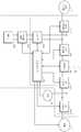
도 1은 본 발명의 일 실시 예에 따른 전력 저장 시스템을 나타내는 도면이다.1 is a diagram illustrating a power storage system in accordance with an embodiment of the present invention.
도 1을 참조하면, 본 실시 예에 따른 전력 저장 시스템(1)은 발전 시스템(2), 계통(3)과 연계하여 부하(4)에 전력을 공급한다.Referring to FIG. 1, the power storage system 1 according to the present embodiment supplies power to the
발전 시스템(2)은 에너지원을 이용하여 전력을 생산하여 전력 저장 시스템(1)에 공급한다. 발전 시스템(2)은 태양광 발전 시스템, 풍력 발전 시스템, 조력 발전 시스템 등 신 재생 에너지를 이용하여 전력을 생산하는 발전 시스템을 모두 포함할 수 있다.The
계통(3)은 발전소, 변전소, 송전선 등을 구비한다. 계통(3)은 전력 저장 시스템(1)으로 전력을 인가하여 부하(4) 및/또는 배터리(300)에 전력이 공급되도록 한다. 또는 계통(3)은 전력 저장 시스템(1)으로부터 전력을 공급받는다.The
부하(4)는 발전 시스템(2)에서 생산된 전력, 배터리(300)에 저장된 전력, 또는 계통(3)으로부터 공급된 전력을 소비하여, 예를 들면 가정, 공장 등일 수 있다.The
전력 저장 시스템(1)은 발전 시스템(2)에서 생성한 전력을 배터리(300)에 저장하고, 생산한 전력을 계통(3)에 공급할 수 있다. 또한 전력 저장 시스템(1)은 배터리(300)에 저장된 전력을 계통(3)에 공급하거나, 계통(3)으로부터 공급된 전력을 배터리(300)에 저장할 수 있다. 또한 전력 저장 시스템(1)은 계통(3)에서 정전이 발생하는 경우에는 UPS(uninterruptible power supply) 동작을 수행한다.The power storage system 1 can store the power generated in the
전력 저장 시스템(1)은 전력 변환을 제어하는 전력 변환 시스템(PCS: power conversion system, 이하 'PCS'라함)(100), 시스템 관리부(BMS: battery management system, 이하 '시스템 BMS'라 함)(200) 및 배터리(300)를 포함한다.The power storage system 1 includes a power conversion system (PCS) 100 for controlling power conversion, a battery management system (BMS) 200 and a
PCS(100)는 발전 시스템(2), 계통, 배터리(300)의 전력을 적절한 전력으로 변환하여 필요한 곳에 공급한다. PCS(100)는 전력 변환부(110), DC 링크부(120), 인버터(130), 컨버터(140), 제1 스위치(150), 제2 스위치(160), 통합 제어기(170)를 포함한다.The PCS 100 converts the power of the
전력 변환부(110)는 발전 시스템(2)과 DC 링크부(120) 사이에 연결된다. 전력 변환부(110)는 발전 시스템(2)에서 생산한 전력을 DC 링크부(120)로 전달하며, 이때 출력 전압을 직류 링크 전압으로 변환한다.The
전력 변환부(110)는 발전 시스템(2)의 종류에 따라서 컨버터, 정류회로 등으로 구성될 수 있다. 발전 시스템(2)이 직류의 전력을 생산하는 경우, 전력 변환부(110)는 직류 전력을 직류 전력으로 변환하기 위한 컨버터일 수 있다. 발전 시스템(2) 교류의 전력을 발생시키는 경우, 전력 변환부(110)는 교류 전력을 직류 전력으로 변환하기 위한 정류회로일 수 있다. 특히, 발전 시스템(2)이 태양광으로 전력을 생산하는 경우, 전력 변환부(110)는 일사량, 온도 등의 변화에 따라서 발전 시스템(2)에서 생산하는 전력을 최대로 얻을 수 있도록 최대 전력 포인트 추적(maximum power point tracking) 제어를 수행하는 MPPT 컨버터를 포함할 수 있다.The
DC 링크부(120)는 전력 변환부(110)와 인버터(130) 사이에 연결된다. DC 링크부(120)는 발전 시스템(2) 또는 계통(3)의 순시 전압 강하, 부하(4)에서의 피크 부하를 발생을 방지하여 직류 링크 전압이 안정적으로 유지되도록 한다.The
인버터(130)는 DC 링크부(120)와 제1 스위치(15) 사이에 연결되는 전력 변환기이다. 인버터(13)는 방전 모드에서 발전 시스템(2) 및/또는 배터리(300)로부터 출력된 직류 링크 전압을 계통(3)의 교류 전압으로 변환하여 출력한다. 또한 인버터(130)는 충전 모드에서 계통(3)의 전력을 배터리(300)에 저장하기 위하여, 계통(3)의 교류 전압을 정류하고 직류 링크 전압으로 변환하여 출력하는 정류 회로를 포함할 수 있다. 즉 인버터(130)는 입력 및 출력의 방향이 변할 수 있는 양방향 인버터일 수 있다.The
인버터(130)는 계통(3)으로 출력되는 교류 전압에서 고조파를 제거하기 위한 필터, 출력되는 교류 전압의 위상과 계통(3)의 교류 전압의 위상을 동기화시키기 위한 위상 동기 루프(PLL) 회로 등을 포함할 수 있다. 그 밖에, 인버터(130)는 전압 변동 범위 제한, 역률 개선, 직류 성분 제거, 과도현상(transient phenomena) 보호 등과 같은 기능을 수행할 수 있다. 인버터(130)는 사용되지 않을 때 전력 소비를 최소화 하기 위하여 동작을 중지시킬 수도 있다.The
컨버터(140)는 DC 링크부(120)와 배터리(300) 사이에 연결되는 전력 변환 장치이다. 컨버터(140)는 방전 모드에서 배터리(300)에 저장된 전력을 인버터(130)에서 요구하는 전압 레벨 즉, 직류 링크 전압으로 DC-DC 변환하여 출력한다. 또한 컨버터(140)는 충전 모드에서 전력 변환부(110)에서 출력되는 전력이나 인버터(130)에서 출력되는 전력을 배터리(300)에서 요구하는 전압 레벨, 즉 충전 전압으로 DC-DC 변환한다. 즉, 컨버터(140)는 입력 및 출력의 방향이 변할 수 있는 양방향 컨버터일 수 있다. 컨버터(140)는 배터리(300)의 충전 도는 방전이 필요 없는 경우에는 동작을 중지시켜 전력 소비를 최소화 할 수도 있다.The
제1 스위치(150) 및 제2 스위치(160)는 인버터(130)와 계통(3) 사이에 직렬로 연결되며, 통합 제어기(170)의 제어에 따라서 온/오프 동작을 수행하여 발전 시스템(2)과 계통(3) 사이의 전류의 흐름을 제어한다. 제1 스위치(15)와 제2 스위치(16)는 발전 시스템(2), 계통(3) 및 배터리(300)의 상태에 따라서 온/오프가 결정될 수 있다. 예를 들어, 부하(4)에서 요구되는 전력량이 큰 경우, 제1 스위치(150) 및 제2 스위치(160)를 모두 온 상태로 하여 발전 시스템(2), 계통(3)의 전력이 모두 사용될 수 있도록 한다. 물론 발전 시스템(2) 및 계통(3)으로부터의 전력만으로는 부하(4)에서 요구하는 전력량을 충족시키지 못하는 경우에 배터리(300)에 저장된 전력이 부하(4)에 공급될 수도 있다. 반면에, 계통(3)에서 정전이 발생한 경우, 제2 스위치(160)를 오프 상태로 하고 제1 스위치(150)를 온 상태로 한다. 이로 인하여 발전 시스템(2) 또는 배터리(300)로부터의 전력을 부하(4)에 공급할 수 있으며, 부하(4)로 공급되는 전력이 계통(3) 측으로 흐르는, 즉 단독운전을 방지하여 계통(3)의 전력선 등에서 작업하는 인부가 감전되는 등의 사고를 방지할 수 있게 한다.The
통합 제어기(170)는 발전 시스템(2), 계통(3), 배터리(300) 및 부하(4)의 상태를 모니터링 하고, 모니터링 결과에 따라서 전력 변환부(110), 인버터(130), 컨버터(140), 제1 스위치(150), 제2 스위치(160) 및 시스템 BMS(200)를 제어한다. 통합 제어기(170)가 모니터링 하는 사항은 계통(3)에 정전이 발생하였는지 여부, 발전 시스템(2)에서 전력이 생산되는지 여부를 포함할 수 있다. 또한 통합 제어기(170)는 발전 시스템(2)의 전력 생산량, 배터리(300)의 충전 상태, 부하(4)의 전력 소비량, 시간 등을 모니터링 할 수 있다.The
시스템 BMS(200)는 배터리(300)에 연결되며, 통합 제어기(170)의 제어에 따라 배터리(300)의 충전 및 방전 동작을 제어한다. 시스템 BMS(200)는 배터리(300)를 보호하기 위하여, 과충전 보호 기능, 과방전 보호 기능, 과전류 보호 기능, 과전압 보호 기능, 과열 보호 기능 등을 수행할 수 있다. 이를 위해, 시스템 BMS(200)는 배터리(300)의 전압, 전류, 온도, 잔여 전력량, 수명, 충전 상태 등을 모니터링 하고, 모니터링 결과를 통합 제어기(170)에 전송할 수 있다. 또한 본 실시 예에 따른 시스템 BMS(200)는 측정된 OCV(open circuit voltage)를 수신하여, 초기 SOC(state of charge)를 추정할 수 있으며, 구체적인 방법에 대해서는 도 2 내지 도 10에서 자세히 설명하도록 한다.The
배터리(300)는 발전 시스템(2)에서 생산된 전력 또는 계통(3)의 전력을 공급 받아 저장하고, 부하(4) 또는 계통(3)에 저장하고 있는 전력을 공급한다.The
배터리(300)는 적어도 하나 이상의 직렬 및/또는 병렬로 연결된 적어도 하나의 배터리 랙(rack)을 포함할 수 있다. 여기서, 배터리 랙은 배터리(300)를 구성하는 하위 구성요소이다. 또한 각각의 배터리 랙은 직렬 및/또는 병렬로 연결된 적어도 하나의 배터리 트레이(tray)를 포함할 수 있다. 여기서 배터리 트레이는 배터리 랙을 구성하는 하위 구성요소이다. 또한 각각의 배터리 트레이는 복수의 배터리 셀을 포함할 수 있다. 이러한 배터리(300)는 다양한 종류의 배터리 셀로 구현될 수 있으며, 예를 들어 니켈-카드뮴 전지(nickel-cadmium battery), 납 축전지, 니켈-수소 전지(NiMH: nickel metal hydride battery), 리튬-이온 전지(lithium ion battery), 리튬 폴리머 전지(lithium polymer battery) 등 일 수 있다.The
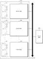
도 2는 도 1 중 배터리 및 시스템 BMS를 나타내는 도면이다. 도 2를 참조하면, 배터리(300)는 적어도 하나 이상의 배터리 트레이들(310, 330, 350) 및 배터리 트레이(310, 330, 350)와 동일한 개수의 트레이 BMS(320, 340, 360)를 포함한다. 도 2에서 배터리(300)는 시스템 BMS(200)와 버스라인으로 연결되어 양자간 데이터 통신을 수행하는데, 이에 국한되지 않고 다양한 방식의 데이터 통신이 가능하다. 예를 들어 시스템 BMS(200)와 트레이 BMS(320, 340, 360) 사이의 통신 방식으로는 CAN 통신이 사용될 수 있다. 그러나 이에 한정되는 것은 아니며 버스라인을 사용하는 다양한 통신이 가능하다. 뿐만 아니라 버스 라인을 사용하지 않는 통신 방식이 사용될 수도 있을 것이다.FIG. 2 is a view showing the battery and system BMS in FIG. 1; FIG. 2, the
하나의 배터리 트레이(310)는 하나 또는 둘 이상의 배터리 셀(311-1 내지 311-n)을 포함할 수 있다. 한편, 배터리(300)가 전력 저장 시스템(1)에 사용되는 경우, 도 2에서 도시한 311-1 내지 311-n은 배터리(300)를 구성하는 배터리 랙 또는 배터리 셀일 수도 있다. 여기서는 311-1 내지 311-n이 복수의 배터리 셀인 경우로 한정하여 설명하도록 한다. 다만, 이를 복수의 배터리 트레이 또는 복수의 배터리 랙으로 확장하여 적용할 수 있음은 당업자에게 자명하도록 할 것이다.One
도 3에는 어느 한 트레이 BMS(320)의 상세도가 개시되어 있다. 도 3을 참조하면, 트레이 BMS(320)는 센싱부(321), 내부 전원 공급부(322), 셀 밸런싱부(323), 보호 회로부(324) 통신부(325) 및 MCU(main control unit)(326)를 포함한다.3 shows a detailed view of one of the
센싱부(321)는 배터리 트레이(310) 전체 전류, 배터리 트레이(310) 전체 전압, 배터리 트레이(310) 온도 및 배터리 셀 주변 온도를 측정하여 MCU(220)에 전달한다. 또한 센싱부(321)는 배터리 트레이(310) 전체 전류, 배터리 트레이(310) 전체 전압, 배터리 트레이(310) 온도 및 배터리 셀 주변 온도에 기초하여 OCV를 측정한다. 배터리 셀(311-1 내지 311-n)이 충전/방전 될 때 화학적 성분에 의하여 허 전압(over voltage)이 발생하는데, 이는 시간이 지나면서 소멸된다. 센싱부(321)는 이와 같이 배터리 셀(311-1 내지 311-n)이 충전/방전 된 후 허 전압 성분이 소멸된 이후에 각 배터리 셀(311-1 내지 311-n)의 OCV를 측정한다. 여기서 허 전압 성분이 완전히 소멸될 수는 없으므로, 시스템 BMS(200)는 배터리 셀(311-1 내지 311-n)의 전류가 3A 이하인 경우에 OCV를 측정하도록 제어한다.The
내부 전원 공급부(322)는 일반적으로 보조 배터리를 이용하여 트레이 BMS(200)에 전원을 공급한다. 셀 밸런싱부(323)는 배터리 각 셀(311-1 내지 311-n)의 충전상태의 균형을 맞춘다. 즉, 충전상태가 비교적 높은 셀은 방전시키고, 충전상태가 비교적 낮은 셀은 충전시킬 수 있다. 보호 회로부(324)는 펌웨어(firmware)를 이용하여 외부의 충격, 과전류, 저전압 등으로부터 배터리(300)를 보호하기 위한 회로 이다. 통신부(325)는 배터리(300)와 시스템 BMS(200) 사이의 데이터 통신을 수행하며, 버스라인 등의 다양한 방식을 이용하여 통신을 수행할 수 있다. 본 실시 예에서 통신부(325)는 특히, 측정한 OCV를 시스템 BMS(200)로 전송한다. MCU(326)는 트레이 BMS(320)를 전체 제어한다.The internal
도 4는 도 2 중 일 실시 예에 따른 시스템 BMS(200)의 상세 도 이다. 도 4를 참조하면, 시스템 BMS(200)는 OCV 산출부(250) 및 SOC 추정부(260)를 포함한다.FIG. 4 is a detailed view of a
시스템 BMS(200)는 적어도 하나 이상의 배터리 트레이(310, 330, 350)에 대한 OCV 측정값을 각 트레이 BMS(320, 340, 360)내의 통신부(325)로부터 수신한다.The
OCV 산출부(250)는 전원이 온 되면, 배터리 트레이들(310, 330, 350) 각각으로부터 OCV를 수신하고, OCV 측정값에 따라 복수의 배터리 셀(311-1 내지 311-n, 331-1 내지 331-n, 351-1 내지 351-n)의 최종 OCV를 산출한다. 여기서 트레이 BMS(320, 340, 360)의 센싱부(321)가 OCV를 측정할 때, 허 전압 성분이 완전히 소멸될 수는 없으므로, OCV 산출부(250)는 배터리 셀(311-1 내지 311-n, 331-1 내지 331-n, 351-1 내지 351-n)의 전류가 3A 이하인 경우에 OCV를 측정하도록 제어하는 제어 신호를 배터리 트레이들(310, 330, 350)에게 전송한다.When the power is turned on, the
SOC 추정부(260)는 SOC 테이블로부터 산출된 최종 OCV에 해당하는 SOC 값을 추출하고, 추출된 SOC 값을 초기 SOC로 추정한다. 예를 들어 시간 경과에 따른 배터리(300) 온도, OCV 별 SOC를 SOC 테이블로 구성할 수 있다.The
도 5는 도 2 중 다른 실시 예에 따른 시스템 BMS(200)의 상세 도 이다. 도 5를 참조하면, 시스템 BMS(200)는 연산부(210), OCV 산출부(250) 및 SOC 추정부(260)를 포함한다.FIG. 5 is a detailed view of a
연산부(210)는 전원이 온 되면, 배터리 트레이들(310, 330, 350) 각각으로부터 OCV를 수신하고, 각 배터리 트레이들(310, 330, 350) 별로 최소 OCV 및 최대 OCV를 제외한 복수의 배터리 셀(311-1 내지 311-n, 331-1 내지 331-n, 351-1 내지 351-n)의 OCV 평균을 연산한다.When the power is turned on, the
OCV 산출부(250)는 연산부(210)로부터 출력되는 OCV 평균에 복수의 배터리 셀(311-1 내지 311-n, 331-1 내지 331-n, 351-1 내지 351-n) 개수를 곱하여 최종 OCV를 산출한다.The
SOC 추정부(260)는 SOC 테이블로부터 산출된 최종 OCV에 해당하는 SOC 값을 추출하고, 추출된 SOC 값을 초기 SOC로 추정한다.The
도 6은 도 2 중 또 다른 실시 예에 따른 시스템 BMS(200)의 상세 도 이다. 도 6을 참조하면, 시스템 BMS(200)는 샘플링부(220), OCV 산출부(250) 및 SOC 추정부(260)를 포함한다.FIG. 6 is a detailed view of a
샘플링부(220)는 전원이 온 되면, 각 배터리 트레이(310, 330, 350)로부터 소정 개수의 배터리 셀을 샘플링하고, 샘플링된 배터리 셀의 OCV를 수신한다.When the power is turned on, the
OCV 산출부(250)는 샘플링된 배터리 셀의 OCV 평균을 산출하고, 산출된 OCV 평균에 복수의 배터리 셀(311-1 내지 311-n, 331-1 내지 331-n, 351-1 내지 351-n) 개수를 곱하여 최종 OCV를 산출한다.The
SOC 추정부(260)는 SOC 테이블로부터 산출된 최종 OCV에 해당하는 SOC 값을 추출하고, 추출된 SOC 값을 초기 SOC로 추정한다.The
도 7은 도 2 중 또 다른 실시 예에 따른 시스템 BMS(200)의 상세 도 이다. 도 7을 참조하면, 시스템 BMS(200)는 데이터 저장부(230), 비교부(240), OCV 산출부(250) 및 SOC 추정부(260)를 포함한다. 데이터 저장부(230)에는 이전의 SOC 저장 시간이 저장되어 있다. 비교부(240)는 전원이 온 되면, 데이터 저장부(230)에 저장된 이전 SOC 저장 시간 및 기준 시간을 비교한다. OCV 산출부(250)는 비교부(240)의 비교 결과, 이전 SOC 저장 시간이 기준 시간 이상인 경우, 복수의 배터리 셀(311-1 내지 311-n, 331-1 내지 331-n, 351-1 내지 351-n) 각각의 OCV를 수신하고 이들을 합하여, 상기 복수의 배터리 셀의 최종 OCV로 산출한다. SOC 추정부(260) SOC 테이블로부터 산출된 최종 OCV에 해당하는 SOC 값을 추출하고, 추출된 SOC 값을 초기 SOC로 추정한다. 그러나 비교부(240)의 비교 결과 이전 SOC 저장 시간이 기준 시간 미만인 경우, SOC 추정부(260)는 데이터 저장부(230)에 저장된 이전 SOC 값을 초기 SOC로 추정한다.FIG. 7 is a detailed view of a
이는 배터리(300)의 초기 SOC 설정을 OCV로만 하면, 정확도가 떨어진다. 따라서 전원 온 시에 OCV로만 초기 SOC를 추정하는 것이 아니라, SOC 값을 주기적으로 데이터 저장부(230)에 저장하여, 전원 온 시에 이전 SOC 저장 시간이 기준 시간 이상이면 OCV를 측정하여 SOC를 추정하고, 기준시간 이하이면 이전에 저장된 SOC 값을 초기 SOC로 추정한다. 여기서 기준시간은 복수의 배터리 셀(311-1 내지 311-n, 331-1 내지 331-n, 351-1 내지 351-n)이 자기 방전에 의해 SOC가 10%로 감소하는데 걸리는 시간으로 예를 들면 3개월 일 수 있다.If the initial SOC setting of the
이하, 도 8 내지 도 11을 참조하여 초기 SOC 추정을 위한 시스템 BMS(200)의 제어 방법을 상세히 설명한다.Hereinafter, a method of controlling the
도 8은 도 1에 도시된 시스템 BMS의 제1 제어 방법을 보이는 흐름도 이다.FIG. 8 is a flowchart showing a first control method of the system BMS shown in FIG. 1. FIG.
도 8을 참조하면, 시스템 BMS(200)는 장치 전원이 온 되었는지 판단하고(801단계), 장치에 전원이 온 된 경우 배터리(300) 전류가 3A 이하인지 판단한다(803단계). 배터리 셀이 충전/방전 될 때 화학적 성분에 의하여 허 전압(over voltage)이 발생하는데, 이는 시간이 지나면서 소멸된다. 이와 같이 배터리 셀이 충전/방전 된 후 허 전압 성분이 소멸된 이후에 각 배터리 셀의 OCV를 측정하는데, 허 전압 성분이 완전히 소멸될 수는 없으므로, 배터리 셀의 전류가 3A 이하인 경우에 OCV를 측정하도록 트레이 BMS(320, 340, 360)를 제어한다.Referring to FIG. 8, the
전류가 3A 이하인 경우, 시스템 BMS(200)는 수신한 각 배터리 셀(311-1 내지 311-n, 331-1 내지 331-n, 351-1 내지 351-n)의 OCV를 모두 합하여 최종 OCV를 산출한다(805단계).When the current is equal to or less than 3A, the
최종 OCV 산출이 완료되면, 시스템 BMS(200)는 SOC 테이블로부터 산출된 최종 OCV에 해당하는 SOC 값을 추출하고, 추출된 SOC 값을 초기 SOC로 추정한다(807단계). 예를 들어 시간 경과에 따른 배터리(300) 온도, OCV 별 SOC를 SOC 테이블로 구성할 수 있다.When the final OCV calculation is completed, the
도 9는 도 1에 도시된 시스템 BMS의 제2 제어 방법을 보이는 흐름도 이다.FIG. 9 is a flowchart showing a second control method of the system BMS shown in FIG. 1. FIG.
도 9를 참조하면, 시스템 BMS(200)는 장치 전원이 온 되었는지 판단하고(901단계), 장치에 전원이 온 된 경우 배터리 트레이들(310, 330, 350) 각각으로부터 OCV를 수신한다(903단계).Referring to FIG. 9, the
다음에 시스템 BMS(200)는 각 배터리 트레이들(310, 330, 350) 별로 최소 OCV 및 최대 OCV를 제외한 복수의 배터리 셀(311-1 내지 311-n, 331-1 내지 331-n, 351-1 내지 351-n)의 OCV 평균을 연산한다(905단계).Next, the
OCV 평균 연산이 완료되면, 시스템 BMS(200)는 OCV 평균에 복수의 배터리 셀(311-1 내지 311-n, 331-1 내지 331-n, 351-1 내지 351-n) 개수를 곱하여 최종 OCV를 산출한다(907단계).When the OCV average operation is completed, the
최종 OCV 산출이 완료되면, 시스템 BMS(200)는 SOC 테이블로부터 산출된 최종 OCV에 해당하는 SOC 값을 추출하고, 추출된 SOC 값을 초기 SOC로 추정한다(909단계).When the final OCV calculation is completed, the
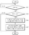
도 10은 도 1에 도시된 시스템 BMS의 제3 제어 방법을 보이는 흐름도 이다.10 is a flowchart illustrating a third control method of the system BMS shown in FIG.
도 10을 참조하면, 시스템 BMS(200)는 장치 전원이 온 되었는지 판단하고(1001단계), 장치에 전원이 온 된 경우 시스템 BMS(200)는 각 배터리 트레이(310, 330, 350)로부터 소정 개수의 배터리 셀을 샘플링한다(1003단계).Referring to FIG. 10, the
다음에 시스템 BMS(200)는 샘플링된 각 배터리 셀의 OCV를 수신하고, 샘플링된 배터리 셀의 평균을 산출한다(1005단계).Next, the
샘플링된 배터리 셀의 평균 산출이 완료되면, 시스템 BMS(200)는 산출된 OCV 평균에 복수의 배터리 셀(311-1 내지 311-n, 331-1 내지 331-n, 351-1 내지 351-n) 개수를 곱하여 최종 OCV를 산출한다(1007단계).When the average calculation of the sampled battery cells is completed, the
최종 OCV 산출이 완료되면, 시스템 BMS(200)는 SOC 테이블로부터 산출된 최종 OCV에 해당하는 SOC 값을 추출하고, 추출된 SOC 값을 초기 SOC로 추정한다(1009단계).When the final OCV calculation is completed, the
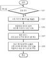
도 11은 도 1에 도시된 시스템 BMS의 제4 제어 방법을 보이는 흐름도 이다.11 is a flowchart showing a fourth control method of the system BMS shown in FIG.
도 11을 참조하면, 시스템 BMS(200)는 장치 전원이 온 되었는지 판단하고(1101단계), 장치에 전원이 온 된 경우 시스템 BMS(200)는 데이터 저장부(230)에 저장된 이전 SOC 저장 시간이 기준 시간 미만인지 판단한다(1103단계). 여기서 기준시간은 복수의 배터리 셀(311-1 내지 311-n, 331-1 내지 331-n, 351-1 내지 351-n)이 자기 방전에 의해 SOC가 10%로 감소하는데 걸리는 시간으로 예를 들면 3개월 일 수 있다.Referring to FIG. 11, the
이전 SOC 저장 시간이 기준 시간 미만인 경우, 시스템 BMS(200)는 데이터 저장부(230)에 저장된 이전 SOC 값을 초기 SOC로 추정한다(1105단계).If the previous SOC storage time is less than the reference time, the
그러나 이전 SOC 저장 시간이 기준 시간 이상인 경우, 시스템 BMS(200)는 수신된 각 배터리 셀의 OCV 측정값을 모두 합하여 최종 OCV를 산출한다(1107단계).However, if the previous SOC storage time is longer than the reference time, the
최종 OCV 산출이 완료되면, 시스템 BMS(200)는 SOC 테이블로부터 산출된 최종 OCV에 해당하는 SOC 값을 추출하고, 추출된 SOC 값을 초기 SOC로 추정한다(1109단계).When the final OCV calculation is completed, the
본 발명에서 설명하는 특정 실행들은 일 실시 예들로서, 어떠한 방법으로도 본 발명의 범위를 한정하는 것은 아니다. 명세서의 간결함을 위하여, 종래 전자적인 구성들, 제어 시스템들, 소프트웨어, 상기 시스템들의 다른 기능적인 측면들의 기재는 생략될 수 있다. 또한, 도면에 도시된 구성 요소들 간의 선들의 연결 또는 연결 부재들은 기능적인 연결 및/또는 물리적 또는 회로적 연결들을 예시적으로 나타낸 것으로서, 실제 장치에서는 대체 가능하거나 추가의 다양한 기능적인 연결, 물리적인 연결, 또는 회로 연결들로서 나타내어질 수 있다. 또한, “필수적인”, “중요하게” 등과 같이 구체적인 언급이 없다면 본 발명의 적용을 위하여 반드시 필요한 구성 요소가 아닐 수 있다.The specific acts described in the present invention are, by way of example, not intended to limit the scope of the invention in any way. For brevity of description, descriptions of conventional electronic configurations, control systems, software, and other functional aspects of such systems may be omitted. Also, the connections or connecting members of the lines between the components shown in the figures are illustrative of functional connections and / or physical or circuit connections, which may be replaced or additionally provided by a variety of functional connections, physical Connection, or circuit connections. Also, unless stated otherwise such as " essential ", " importantly ", etc., it may not be a necessary component for application of the present invention.
본 발명의 명세서(특히 특허청구범위에서)에서 “상기”의 용어 및 이와 유사한 지시 용어의 사용은 단수 및 복수 모두에 해당하는 것일 수 있다. 또한, 본 발명에서 범위(range)를 기재한 경우 상기 범위에 속하는 개별적인 값을 적용한 발명을 포함하는 것으로서(이에 반하는 기재가 없다면), 발명의 상세한 설명에 상기 범위를 구성하는 각 개별적인 값을 기재한 것과 같다. 마지막으로, 본 발명에 따른 방법을 구성하는 단계들에 대하여 명백하게 순서를 기재하거나 반하는 기재가 없다면, 상기 단계들은 적당한 순서로 행해질 수 있다. 반드시 상기 단계들의 기재 순서에 따라 본 발명이 한정되는 것은 아니다. 본 발명에서 모든 예들 또는 예시적인 용어(예들 들어, 등등)의 사용은 단순히 본 발명을 상세히 설명하기 위한 것으로서 특허청구범위에 의해 한정되지 않는 이상 상기 예들 또는 예시적인 용어로 인해 본 발명의 범위가 한정되는 것은 아니다. 또한, 당업자는 다양한 수정, 조합 및 변경이 부가된 특허청구범위 또는 그 균등물의 범주 내에서 설계 조건 및 팩터에 따라 구성될 수 있음을 알 수 있다.The use of the terms " above " and similar indication words in the specification of the present invention (particularly in the claims) may refer to both singular and plural. In addition, in the present invention, when a range is described, it includes the invention to which the individual values belonging to the above range are applied (unless there is contradiction thereto), and each individual value constituting the above range is described in the detailed description of the invention The same. Finally, the steps may be performed in any suitable order, unless explicitly stated or contrary to the description of the steps constituting the method according to the invention. The present invention is not necessarily limited to the order of description of the above steps. The use of all examples or exemplary language (e.g., etc.) in this invention is for the purpose of describing the present invention only in detail and is not to be limited by the scope of the claims, It is not. It will also be appreciated by those skilled in the art that various modifications, combinations, and alterations may be made depending on design criteria and factors within the scope of the appended claims or equivalents thereof.
1: 전력 저장 시스템100: 전력 변환 시스템(PCS)
200: 시스템 BMS210: 연산부
220: 샘플링부230: 데이터 저장부
240: 비교부250: OCV 산출부
260: SOC 추정부300: 배터리
310: 배터리 트레이320: 트레이 BMS1: power storage system 100: power conversion system (PCS)
200: system BMS 210:
220: Sampling unit 230: Data storage unit
240: comparator 250: OCV calculator
260: SOC estimation unit 300: battery
310: Battery tray 320: Tray BMS
Claims (12)
Translated fromKorean전원이 온 되면, 상기 각 배터리 트레이로부터 복수의 배터리 셀 각각의 OCV(open circuit voltage) 측정값을 수신하고, 상기 측정값에 따라 상기 복수의 배터리 셀의 최종 OCV를 산출하는 OCV 산출부;
SOC(state of charge) 테이블로부터 상기 최종 OCV에 해당하는 SOC 값을 추출하고, 상기 추출된 SOC 값을 초기 SOC로 추정하는 SOC 추정부;
주기적으로 SOC값을 저장하고, 상기 SOC값이 저장된 SOC 저장시간을 저장하는 데이터 저장부; 및
전원이 온 되면, 상기 데이터 저장부에 마지막으로 저장된 SOC 저장시간과 현재 시간의 차이를 기준 시간과 비교하는 비교부;를 포함하고,
상기 기준 시간은 상기 복수의 배터리 셀이 자기 방전하여 SOC 값이 변하는 비율을 고려하여 미리 설정된 시간인 것을 특징으로 하며,
상기 OCV 산출부는 상기 비교부의 비교 결과, 마지막 SOC 저장 시간과 현재 시간의 차이가 기준 시간 이상인 경우, 상기 복수의 배터리 셀의 최종 OCV를 산출하는 것을 특징으로 하는 배터리 팩의 제어 장치.A control apparatus for a battery pack including at least one battery tray composed of a plurality of battery cells,
An OCV calculating unit for receiving an OCV (open circuit voltage) measurement value of each of a plurality of battery cells from each of the battery trays and calculating a final OCV of the plurality of battery cells according to the measured value when the power is turned on;
An SOC estimator for extracting an SOC value corresponding to the final OCV from an SOC (state of charge) table and estimating the extracted SOC value as an initial SOC;
A data storage unit for periodically storing the SOC value and storing the SOC storage time at which the SOC value is stored; And
And a comparison unit comparing the difference between the SOC storage time last stored in the data storage unit and the current time with a reference time when the power is turned on,
Wherein the reference time is a predetermined time in consideration of a rate at which the plurality of battery cells are self-discharged to change the SOC value,
Wherein the OCV calculation unit calculates the final OCV of the plurality of battery cells when the difference between the last SOC storage time and the current time is greater than or equal to a reference time as a result of the comparison unit.
상기 OCV 산출부는
상기 배터리 셀의 OCV 측정 전류를 기준전류 이하로 설정하는 것을 특징으로 하는 배터리 팩의 제어 장치.The method according to claim 1,
The OCV calculation unit
Wherein the OCV measuring current of the battery cell is set to be equal to or less than a reference current.
상기 기준전류는 3A인 것을 특징으로 하는 배터리 팩의 제어 장치.3. The method of claim 2,
Wherein the reference current is 3A.
최소 OCV 및 최대 OCV를 제외한 상기 배터리 셀의 OCV 평균을 연산하는 연산부를 더 포함하는 것을 특징으로 하는 배터리 팩의 제어 장치.The method according to claim 1,
Further comprising an operation unit for calculating an OCV average of the battery cells except the minimum OCV and the maximum OCV.
상기 OCV 산출부는
상기 연산된 OCV 평균에 상기 배터리 트레이에 직렬로 연결된 배터리 셀들의 개수를 곱하여 최종 OCV를 산출하는 것을 특징으로 하는 배터리 팩의 제어 장치.5. The method of claim 4,
The OCV calculation unit
And the final OCV is calculated by multiplying the calculated OCV average by the number of battery cells connected in series to the battery tray.
소정 개수의 배터리 셀을 샘플링하는 샘플링부를 더 포함하는 것을 특징으로 하는 배터리 팩의 제어 장치.The method according to claim 1,
Further comprising a sampling unit for sampling a predetermined number of battery cells.
상기 OCV 산출부는
상기 샘플링된 배터리 셀들의 OCV 평균을 산출하고, 상기 OCV 평균에 상기 배터리 트레이에 직렬로 연결된 배터리 셀들의 개수를 곱하여 최종 OCV를 산출하는 것을 특징으로 하는 배터리 팩의 제어 장치.The method according to claim 6,
The OCV calculation unit
Wherein the OCV average of the sampled battery cells is calculated and the final OCV is calculated by multiplying the OCV average by the number of battery cells serially connected to the battery tray.
상기 배터리 셀의 자기 방전이 SOC 10%에 해당하는 기간인 것을 특징으로 하는 배터리 팩의 제어 장치.2. The method of claim 1,
Wherein the self-discharge of the battery cell corresponds to a SOC of 10%.
상기 비교 결과, 마지막 SOC 저장 시간과 현재 시간의 차이가 기준 시간 미만인 경우, 마지막에 저장된 SOC 값을 초기 SOC로 추정하는 것을 특징으로 하는 배터리 팩의 제어 장치.The apparatus of claim 1, wherein the SOC estimator
If the difference between the last SOC storage time and the current time is less than the reference time, estimates the last stored SOC value as the initial SOC.
전원이 온 되면, 상기 각 배터리 트레이로부터 복수의 배터리 셀 각각의 OCV(open circuit voltage) 측정값을 수신하고 상기 측정값에 따라 상기 복수의 배터리 셀의 최종 OCV를 산출하는 OCV 산출부;
SOC(state of charge) 테이블로부터 상기 최종 OCV에 해당하는 SOC 값을 추출하고, 상기 추출된 SOC 값을 초기 SOC로 추정하는 SOC 추정부;
주기적으로 SOC값을 저장하고, 상기 SOC값이 저장된 SOC 저장시간을 저장하는 데이터 저장부; 및
전원이 온 되면, 데이터 저장부에 마지막으로 저장된 SOC 저장시간과 현재 시간의 차이를 기준 시간과 비교하는 비교부;를 포함하고,
상기 기준 시간은 상기 복수의 배터리 셀이 자기 방전하여 SOC 값이 변하는 비율을 고려하여 미리 설정된 시간인 것을 특징으로 하며,
상기 OCV 산출부는 상기 비교부의 비교 결과, 마지막 SOC 저장 시간과 현재 시간의 차이가 기준 시간 이상인 경우, 상기 복수의 배터리 셀의 최종 OCV를 산출하는 것을 특징으로 하는 에너지 저장 시스템.1. An energy storage system comprising at least one battery tray comprised of a plurality of battery cells, said battery tray selectively coupling power to the power generation system and / or system to selectively supply power to the load and / or the system,
An OCV calculating unit for receiving an OCV (open circuit voltage) measurement value of each of a plurality of battery cells from each of the battery trays and calculating a final OCV of the plurality of battery cells according to the measured value, when the power is on;
An SOC estimator for extracting an SOC value corresponding to the final OCV from an SOC (state of charge) table and estimating the extracted SOC value as an initial SOC;
A data storage unit for periodically storing the SOC value and storing the SOC storage time at which the SOC value is stored; And
And a comparison unit comparing the difference between the SOC storage time last stored in the data storage unit and the current time with the reference time when the power is turned on,
Wherein the reference time is a predetermined time in consideration of a rate at which the plurality of battery cells are self-discharged to change the SOC value,
Wherein the OCV calculation unit calculates the final OCV of the plurality of battery cells when the difference between the last SOC storage time and the current time is equal to or greater than a reference time as a result of the comparison unit.
Priority Applications (2)
| Application Number | Priority Date | Filing Date | Title |
|---|---|---|---|
| KR1020110129906AKR101648889B1 (en) | 2011-12-06 | 2011-12-06 | Apparatus for controlling battery pack, and energy storage system including the battery pack |
| US13/554,998US9599675B2 (en) | 2011-12-06 | 2012-07-20 | Apparatus for controlling battery pack, and energy storage system including the apparatus |
Applications Claiming Priority (1)
| Application Number | Priority Date | Filing Date | Title |
|---|---|---|---|
| KR1020110129906AKR101648889B1 (en) | 2011-12-06 | 2011-12-06 | Apparatus for controlling battery pack, and energy storage system including the battery pack |
Publications (2)
| Publication Number | Publication Date |
|---|---|
| KR20130063406A KR20130063406A (en) | 2013-06-14 |
| KR101648889B1true KR101648889B1 (en) | 2016-08-18 |
Family
ID=48524599
Family Applications (1)
| Application Number | Title | Priority Date | Filing Date |
|---|---|---|---|
| KR1020110129906AActiveKR101648889B1 (en) | 2011-12-06 | 2011-12-06 | Apparatus for controlling battery pack, and energy storage system including the battery pack |
Country Status (2)
| Country | Link |
|---|---|
| US (1) | US9599675B2 (en) |
| KR (1) | KR101648889B1 (en) |
Families Citing this family (25)
| Publication number | Priority date | Publication date | Assignee | Title |
|---|---|---|---|---|
| DE102009045526A1 (en)* | 2009-10-09 | 2011-04-14 | SB LiMotive Company Ltd., Suwon | Method for initialization and operation of a battery management system |
| DE102012212654A1 (en)* | 2012-07-19 | 2014-01-23 | Robert Bosch Gmbh | Energy storage for Photovoltaikanalage, energy storage power plant, control device and method for operating an energy storage |
| US9933488B2 (en) | 2012-07-24 | 2018-04-03 | General Electric Company | Open circuit voltage checking for a battery system |
| US20150046105A1 (en)* | 2013-08-09 | 2015-02-12 | Qualcomm Incorporated | Voltage mode fuel gauge |
| CN104737410B (en)* | 2013-09-27 | 2019-03-12 | 松下知识产权经营株式会社 | Diagnostic method of power distribution unit and battery pack |
| CN103515973A (en)* | 2013-10-18 | 2014-01-15 | 国家电网公司 | Energy storage device for improving seasonal load power supply capacity on rural power grid and manufacture method of energy storage device |
| KR101635665B1 (en)* | 2013-10-31 | 2016-07-01 | 주식회사 엘지화학 | Apparatus and method that controls the data of application modules |
| WO2015105923A1 (en)* | 2014-01-07 | 2015-07-16 | Utah State University | Battery control |
| DE102014200096A1 (en)* | 2014-01-08 | 2015-07-09 | Robert Bosch Gmbh | A battery management system for monitoring and controlling the operation of a battery and battery system having such a battery management system |
| CN104122884A (en)* | 2014-07-15 | 2014-10-29 | 虞永义 | Simulation test device of battery management system |
| CN104505550B (en)* | 2014-12-25 | 2017-01-18 | 宁德时代新能源科技股份有限公司 | Passive equalization method and system for lithium iron phosphate battery pack |
| US10293693B2 (en) | 2015-04-21 | 2019-05-21 | Samsung Electronics Co., Ltd. | Battery control method and apparatus, battery module, and battery pack |
| US11594883B2 (en)* | 2018-01-23 | 2023-02-28 | Tdk Corporation | Direct current power supplying system |
| KR102518182B1 (en)* | 2018-02-14 | 2023-04-07 | 현대자동차주식회사 | Apparatus for controlling converter of green car and method thereof |
| CN108615954B (en)* | 2018-04-26 | 2020-09-15 | 常州信息职业技术学院 | Method for improving battery output efficiency of new energy electric vehicle |
| CN110703108A (en)* | 2019-10-14 | 2020-01-17 | 郑州中科新兴产业技术研究院 | Method for determining storage time of battery cell |
| KR102824433B1 (en) | 2019-10-31 | 2025-06-23 | 주식회사 엘지에너지솔루션 | Method for estimating of battery's state of charge and Battery Management System |
| CN110658465A (en)* | 2019-11-01 | 2020-01-07 | 四川长虹电器股份有限公司 | Cadmium-nickel battery management system |
| US11664513B2 (en) | 2019-11-08 | 2023-05-30 | Hyundai Mobis Co., Ltd. | System and method for sensing fuel cell of vehicle |
| KR102390880B1 (en)* | 2019-11-22 | 2022-04-26 | 현대모비스 주식회사 | System and method for sensing fuel cell of vehicle |
| TWI790872B (en)* | 2021-12-23 | 2023-01-21 | 亞福儲能股份有限公司 | Battery management system and battery management method |
| CN114696412B (en)* | 2022-03-23 | 2024-07-23 | 国网北京市电力公司 | Battery energy storage system SOC balance control system, method, device and storage medium |
| KR20230143863A (en)* | 2022-04-06 | 2023-10-13 | 에스케이온 주식회사 | Apparatus and method for determining defect of battery |
| CN120641769A (en)* | 2023-02-21 | 2025-09-12 | 株式会社Lg新能源 | Battery diagnostic device and operating method thereof |
| KR20240162881A (en)* | 2023-05-09 | 2024-11-18 | 주식회사 엘지에너지솔루션 | Battery management apparatus and operating method of the same |
Citations (1)
| Publication number | Priority date | Publication date | Assignee | Title |
|---|---|---|---|---|
| JP2007040991A (en)* | 2005-07-29 | 2007-02-15 | Samsung Sdi Co Ltd | Battery management system and driving method thereof |
Family Cites Families (9)
| Publication number | Priority date | Publication date | Assignee | Title |
|---|---|---|---|---|
| KR100428362B1 (en) | 2001-10-16 | 2004-04-28 | 현대자동차주식회사 | Method of estimating an initial state of charge using an open circuit voltage of battery for vehicles |
| KR20080014207A (en) | 2006-08-10 | 2008-02-14 | 주식회사 엘지화학 | Method for calculating the remaining capacity of the battery pack, a method for determining the open voltage used in the calculation method and apparatus therefor |
| KR100804697B1 (en) | 2006-08-11 | 2008-02-18 | 삼성에스디아이 주식회사 | Battery Management System and Its Driving Method |
| KR100869801B1 (en)* | 2006-09-26 | 2008-11-21 | 삼성에스디아이 주식회사 | Battery management system and its driving method |
| KR101075902B1 (en) | 2007-01-06 | 2011-10-25 | 주식회사 엘지화학 | Battery Pack Case Having Resiliently Flexible Connecting Member |
| JP2008241358A (en)* | 2007-03-26 | 2008-10-09 | Sanyo Electric Co Ltd | Full capacity detection method of battery |
| JP2009017651A (en)* | 2007-07-03 | 2009-01-22 | Lenovo Singapore Pte Ltd | Overvoltage protection system, battery pack and electronic equipment |
| JP4649682B2 (en)* | 2008-09-02 | 2011-03-16 | 株式会社豊田中央研究所 | Secondary battery state estimation device |
| WO2012169062A1 (en)* | 2011-06-10 | 2012-12-13 | 日立ビークルエナジー株式会社 | Battery control device and battery system |
- 2011
- 2011-12-06KRKR1020110129906Apatent/KR101648889B1/enactiveActive
- 2012
- 2012-07-20USUS13/554,998patent/US9599675B2/enactiveActive
Patent Citations (1)
| Publication number | Priority date | Publication date | Assignee | Title |
|---|---|---|---|---|
| JP2007040991A (en)* | 2005-07-29 | 2007-02-15 | Samsung Sdi Co Ltd | Battery management system and driving method thereof |
Also Published As
| Publication number | Publication date |
|---|---|
| US20130144547A1 (en) | 2013-06-06 |
| KR20130063406A (en) | 2013-06-14 |
| US9599675B2 (en) | 2017-03-21 |
Similar Documents
| Publication | Publication Date | Title |
|---|---|---|
| KR101648889B1 (en) | Apparatus for controlling battery pack, and energy storage system including the battery pack | |
| CN103094989B (en) | For managing method and the energy storage system of battery cell | |
| KR101835584B1 (en) | Apparatus for managing battery, and energy storage system | |
| KR101182431B1 (en) | Battery pack, controlling method of the same, and power storage system including the battery pack | |
| US9401616B2 (en) | Battery pack, energy storage system including battery pack, and method of charging battery pack | |
| US9231407B2 (en) | Battery system, method of controlling the same, and energy storage system including the battery system | |
| KR101463115B1 (en) | Battery pack, method of measuring voltage of the battery pack, and energy storage system including the battery pack | |
| KR101678526B1 (en) | Battery system, method for controlling battery system and energy storage system including the same | |
| EP2884575B1 (en) | Battery system and method of connecting battery module to a battery rack | |
| US8716892B2 (en) | Energy storage system and method of controlling the same | |
| US9088164B2 (en) | Battery system, controlling method of the same, and power storage system including the battery pack | |
| EP2325970A2 (en) | Energy management system and grid-connected energy storage system including the energy management system | |
| EP2629388A1 (en) | Power management system | |
| KR20170022417A (en) | Battery system | |
| KR20130024763A (en) | Cell balancing method, cell balancing device and energy storage system including the same | |
| KR101473324B1 (en) | Apparatus for managing battery, method for balancing battery cells, and energy storage system | |
| KR20130066283A (en) | Simulation device of battery system | |
| KR20130062894A (en) | Energy storage system and controlling method the same | |
| KR20130142409A (en) | Battery pack and its control method | |
| KR20170019971A (en) | Battery Pack and Energy Storage System Including Thereof | |
| KR20170019972A (en) | Energy Storage System and Battery Control Method Using Thereof | |
| US20240313275A1 (en) | Battery system |
Legal Events
| Date | Code | Title | Description |
|---|---|---|---|
| PA0109 | Patent application | St.27 status event code:A-0-1-A10-A12-nap-PA0109 | |
| PG1501 | Laying open of application | St.27 status event code:A-1-1-Q10-Q12-nap-PG1501 | |
| R18-X000 | Changes to party contact information recorded | St.27 status event code:A-3-3-R10-R18-oth-X000 | |
| A201 | Request for examination | ||
| PA0201 | Request for examination | St.27 status event code:A-1-2-D10-D11-exm-PA0201 | |
| D13-X000 | Search requested | St.27 status event code:A-1-2-D10-D13-srh-X000 | |
| D14-X000 | Search report completed | St.27 status event code:A-1-2-D10-D14-srh-X000 | |
| E902 | Notification of reason for refusal | ||
| PE0902 | Notice of grounds for rejection | St.27 status event code:A-1-2-D10-D21-exm-PE0902 | |
| E13-X000 | Pre-grant limitation requested | St.27 status event code:A-2-3-E10-E13-lim-X000 | |
| P11-X000 | Amendment of application requested | St.27 status event code:A-2-2-P10-P11-nap-X000 | |
| P13-X000 | Application amended | St.27 status event code:A-2-2-P10-P13-nap-X000 | |
| E701 | Decision to grant or registration of patent right | ||
| PE0701 | Decision of registration | St.27 status event code:A-1-2-D10-D22-exm-PE0701 | |
| GRNT | Written decision to grant | ||
| PR0701 | Registration of establishment | St.27 status event code:A-2-4-F10-F11-exm-PR0701 | |
| PR1002 | Payment of registration fee | St.27 status event code:A-2-2-U10-U11-oth-PR1002 Fee payment year number:1 | |
| PG1601 | Publication of registration | St.27 status event code:A-4-4-Q10-Q13-nap-PG1601 | |
| FPAY | Annual fee payment | Payment date:20190801 Year of fee payment:4 | |
| PR1001 | Payment of annual fee | St.27 status event code:A-4-4-U10-U11-oth-PR1001 Fee payment year number:4 | |
| PR1001 | Payment of annual fee | St.27 status event code:A-4-4-U10-U11-oth-PR1001 Fee payment year number:5 | |
| P22-X000 | Classification modified | St.27 status event code:A-4-4-P10-P22-nap-X000 | |
| R18-X000 | Changes to party contact information recorded | St.27 status event code:A-5-5-R10-R18-oth-X000 | |
| PR1001 | Payment of annual fee | St.27 status event code:A-4-4-U10-U11-oth-PR1001 Fee payment year number:6 | |
| PR1001 | Payment of annual fee | St.27 status event code:A-4-4-U10-U11-oth-PR1001 Fee payment year number:7 | |
| PR1001 | Payment of annual fee | St.27 status event code:A-4-4-U10-U11-oth-PR1001 Fee payment year number:8 | |
| PR1001 | Payment of annual fee | St.27 status event code:A-4-4-U10-U11-oth-PR1001 Fee payment year number:9 | |
| PR1001 | Payment of annual fee | St.27 status event code:A-4-4-U10-U11-oth-PR1001 Fee payment year number:10 |