KR101647314B1 - Conjugated icp and ecr plasma sources for wide ribbon ion beam generation and control - Google Patents
Conjugated icp and ecr plasma sources for wide ribbon ion beam generation and controlDownload PDFInfo
- Publication number
- KR101647314B1 KR101647314B1KR1020117026703AKR20117026703AKR101647314B1KR 101647314 B1KR101647314 B1KR 101647314B1KR 1020117026703 AKR1020117026703 AKR 1020117026703AKR 20117026703 AKR20117026703 AKR 20117026703AKR 101647314 B1KR101647314 B1KR 101647314B1
- Authority
- KR
- South Korea
- Prior art keywords
- cylinder
- plasma
- gas
- source
- diffusion chamber
- Prior art date
- Legal status (The legal status is an assumption and is not a legal conclusion. Google has not performed a legal analysis and makes no representation as to the accuracy of the status listed.)
- Active
Links
Images


Classifications
- H—ELECTRICITY
- H01—ELECTRIC ELEMENTS
- H01J—ELECTRIC DISCHARGE TUBES OR DISCHARGE LAMPS
- H01J37/00—Discharge tubes with provision for introducing objects or material to be exposed to the discharge, e.g. for the purpose of examination or processing thereof
- H01J37/02—Details
- H01J37/04—Arrangements of electrodes and associated parts for generating or controlling the discharge, e.g. electron-optical arrangement or ion-optical arrangement
- H01J37/08—Ion sources; Ion guns
- H—ELECTRICITY
- H01—ELECTRIC ELEMENTS
- H01J—ELECTRIC DISCHARGE TUBES OR DISCHARGE LAMPS
- H01J37/00—Discharge tubes with provision for introducing objects or material to be exposed to the discharge, e.g. for the purpose of examination or processing thereof
- H01J37/30—Electron-beam or ion-beam tubes for localised treatment of objects
- H01J37/317—Electron-beam or ion-beam tubes for localised treatment of objects for changing properties of the objects or for applying thin layers thereon, e.g. for ion implantation
- H01J37/3171—Electron-beam or ion-beam tubes for localised treatment of objects for changing properties of the objects or for applying thin layers thereon, e.g. for ion implantation for ion implantation
- H—ELECTRICITY
- H01—ELECTRIC ELEMENTS
- H01J—ELECTRIC DISCHARGE TUBES OR DISCHARGE LAMPS
- H01J2237/00—Discharge tubes exposing object to beam, e.g. for analysis treatment, etching, imaging
- H01J2237/06—Sources
- H01J2237/061—Construction
- H—ELECTRICITY
- H01—ELECTRIC ELEMENTS
- H01J—ELECTRIC DISCHARGE TUBES OR DISCHARGE LAMPS
- H01J2237/00—Discharge tubes exposing object to beam, e.g. for analysis treatment, etching, imaging
- H01J2237/06—Sources
- H01J2237/065—Source emittance characteristics
- H—ELECTRICITY
- H01—ELECTRIC ELEMENTS
- H01J—ELECTRIC DISCHARGE TUBES OR DISCHARGE LAMPS
- H01J2237/00—Discharge tubes exposing object to beam, e.g. for analysis treatment, etching, imaging
- H01J2237/06—Sources
- H01J2237/08—Ion sources
- H01J2237/0815—Methods of ionisation
- H—ELECTRICITY
- H10—SEMICONDUCTOR DEVICES; ELECTRIC SOLID-STATE DEVICES NOT OTHERWISE PROVIDED FOR
- H10F—INORGANIC SEMICONDUCTOR DEVICES SENSITIVE TO INFRARED RADIATION, LIGHT, ELECTROMAGNETIC RADIATION OF SHORTER WAVELENGTH OR CORPUSCULAR RADIATION
- H10F71/00—Manufacture or treatment of devices covered by this subclass
- H10F71/10—Manufacture or treatment of devices covered by this subclass the devices comprising amorphous semiconductor material
- H10F71/107—Continuous treatment of the devices, e.g. roll-to roll processes or multi-chamber deposition
- H—ELECTRICITY
- H10—SEMICONDUCTOR DEVICES; ELECTRIC SOLID-STATE DEVICES NOT OTHERWISE PROVIDED FOR
- H10F—INORGANIC SEMICONDUCTOR DEVICES SENSITIVE TO INFRARED RADIATION, LIGHT, ELECTROMAGNETIC RADIATION OF SHORTER WAVELENGTH OR CORPUSCULAR RADIATION
- H10F71/00—Manufacture or treatment of devices covered by this subclass
- H10F71/121—The active layers comprising only Group IV materials
- H—ELECTRICITY
- H10—SEMICONDUCTOR DEVICES; ELECTRIC SOLID-STATE DEVICES NOT OTHERWISE PROVIDED FOR
- H10F—INORGANIC SEMICONDUCTOR DEVICES SENSITIVE TO INFRARED RADIATION, LIGHT, ELECTROMAGNETIC RADIATION OF SHORTER WAVELENGTH OR CORPUSCULAR RADIATION
- H10F77/00—Constructional details of devices covered by this subclass
- H10F77/10—Semiconductor bodies
- H10F77/12—Active materials
- H10F77/122—Active materials comprising only Group IV materials
- H10F77/1223—Active materials comprising only Group IV materials characterised by the dopants
- Y—GENERAL TAGGING OF NEW TECHNOLOGICAL DEVELOPMENTS; GENERAL TAGGING OF CROSS-SECTIONAL TECHNOLOGIES SPANNING OVER SEVERAL SECTIONS OF THE IPC; TECHNICAL SUBJECTS COVERED BY FORMER USPC CROSS-REFERENCE ART COLLECTIONS [XRACs] AND DIGESTS
- Y02—TECHNOLOGIES OR APPLICATIONS FOR MITIGATION OR ADAPTATION AGAINST CLIMATE CHANGE
- Y02P—CLIMATE CHANGE MITIGATION TECHNOLOGIES IN THE PRODUCTION OR PROCESSING OF GOODS
- Y02P70/00—Climate change mitigation technologies in the production process for final industrial or consumer products
- Y02P70/50—Manufacturing or production processes characterised by the final manufactured product
Landscapes
- Chemical & Material Sciences (AREA)
- Analytical Chemistry (AREA)
- Electron Sources, Ion Sources (AREA)
- Plasma Technology (AREA)
- Photovoltaic Devices (AREA)
Abstract
Translated fromKoreanDescription
Translated fromKorean본 발명은 넓은 이온 빔 발생 및 조절을 위한 콘쥬게이티드 ICP 및 ECR 플라즈마 소스에 관한 것이다.The present invention relates to a conjugated ICP and ECR plasma source for wide ion beam generation and regulation.
이온 주입기(ion implanters)는 통상적으로 실리콘으로 구성되며 p-타입 혹은 n-타입 도핑에 의해 다른 전도도의 영역들을 갖는 반도체 웨이퍼 내에 생성되는 집적 회로(integrated circuit: IC)의 생산에 널리 사용된다. 이러한 장치에 있어서, 플라즈마 소스가 도펀트 가스를 이온화하기 위해 사용된다. 양이온들의 빔이 상기 소스로부터 추출되고 소정의 에너지로 가속되며, 질량 필터되어 상기 웨이퍼를 향해 이동한다. 상기 이온들이 상기 웨이퍼에 충돌할 때, 이들은 웨이퍼의 특정 깊이까지 침투(상기 이온들의 운동 에너지 및 질량에 따라)하여 상이한 전기 전도도(도펀트 원소의 농도에 따라)의 영역을 상기 웨이퍼 내부에 생성한다. 이러한 영역들의 n- 또는 p-도핑 성질은 상기 웨이퍼 상의 이들의 기하학적 구조에 따라 상기 영역들의 기능성을 결정한다(예를 들면, 트랜지스터 내부의 n-p-n 혹은 p-n-p 정션). 이러한 다수의 도핑 영역들의 상호 연결을 통해, 상기 웨이퍼들은 복합 집적 회로(complex IC)로 변환될 수 있다.BACKGROUND OF THE INVENTION [0002] Ion implanters are widely used in the production of integrated circuits (ICs), typically made of silicon and produced in semiconductor wafers with regions of different conductivity by p-type or n-type doping. In such an apparatus, a plasma source is used to ionize the dopant gas. A beam of positive ions is extracted from the source and accelerated to a predetermined energy, mass filtered and moved toward the wafer. When the ions impinge on the wafer, they penetrate (depending on the kinetic energy and mass of the ions) up to a certain depth in the wafer to create regions of different electrical conductivities (depending on the concentration of the dopant element) within the wafer. The n- or p-doping nature of these regions determines the functionality of the regions in accordance with their geometry on the wafer (e.g., n-p-n or p-n-p junctions within a transistor). Through the interconnections of these multiple doped regions, the wafers can be converted into complex ICs.
대표적인 이온 주입기(50)의 블록도가 도 1에 도시된다. 파워 서플라이(1)는 요구되는 에너지(DC 혹은 RF)를 플라즈마 소스(2)에 전달하여 도핑 가스의 이온화를 가능케 한다. 상기 가스는 질량-플로우 조절 시스템(도시되지 않음)을 통해, 진공 펌핑 시스템에 의해 보장되는 mTorr 범위의 압력 하에서 플라즈마 챔버 내부로 공급된다. 바람직한 도펀트에 따라, 상이한 플로라이드(fluoride) 혹은 하이드라이드(hydride) 도핑 가스들, 예를 들면, BF3, PF3, AsF3, GeF4, B2H6, PH3, AsH3, GeH4 혹은 다른 가스들이 코-캐리어(co-carrier) 가스와 함께 혹은 코-캐리어 가스 없이 도입된다. 상기 플라즈마 챔버는 이온들이 전극들(4)의 조합에 의해 추출되는 개구(aperture, 4)를 갖는다. 상용되는 기술은 상기 플라즈마 챔버 개구가 높은 양(positive)의 포텐셜을 가지며, 제2 전극(억제 전극: suppression electrode)이 음의 포텐셜을 갖고, 마지막으로 제3 전극이 그라운드 포텐셜을 갖는 3극 조합이다. 상기 제2 전극의 역할은 2차 전자들이 상기 플라즈마 챔버로 환류되는 것을 방지하는 것이다. 그러나, 4극, 5극 혹은 Einzel 렌즈들과 같은 기타 추출 전극 조합들 역시 가능하다. 여기된 이온들은 빔(20)을 형성하고, 이는 질량 분석 자석(mass analyzer magnet, 6)을 통과한다. 상기의 추출된 이온 빔은 이온들의 혼합물로 구성된다. 예를 들면, BF3 가스로부터 추출된 빔은 주로 BF3+, BF2+, BF+, B+ 및 F+ 이온들을 포함할 것이다. 그러므로, 질량 분석기를 사용하여 상기 이온 빔으로부터 원하지 않는 성분들을 제거하는 것이 필요하다. 이에 의해, 상기 이온 빔은 원하는 에너지를 가지며 단일 이온 종(BF3의 경우, B+ 이온)으로 구성될 수 있다. 에너지를 원하는 레벨로 감소시키기 위해, 원하는 종들로 구성된 이온들은 감속 스테이지(8)를 통과하며, 감속 스테이지(8)는 일 이상의 전극들을 포함할 수 있다. 상기 감속 스테이지의 결과물은 발산하는 이온 빔이다. 교정 자석(10)이 상기 이온 빔을 확장시키고 이를 평행 리본 이온 빔으로 변환시키는데 사용된다. 각 교정기(10)에 이어서, 상기 리본 빔은 웨이퍼 혹은 대상체를 향해 이동된다. 일부 실시예들에 있어서, 제2 감속 스테이지(12)가 부가될 수 있다. 상기 웨이퍼 혹은 대상체는 웨이퍼 지지체(14)에 부착된다. 웨이퍼 지지체(14)는 수직 모션을 제공하여 상기 웨이퍼가 빔 경로 내에 제공될 수 있으며, 고정된 이온 리본 빔을 통과하며 상하 이동할 수 있다. 또한, 웨이퍼 지지체(14)는 회전 가능하여 이온 주입이 상기 웨이퍼의 표면에 대해 상이한 입사각으로 수행될 수 있다. 상기 웨이퍼가 상기 빔 경로 밖으로 이동되면, 빔 전류가 패러데이(Faraday) 컵(16)에 의해 측정될 수 있다. 상기 빔 전류 값 및 원하는 도오즈량에 근거하여, 상기 웨이퍼의 노출 시간 혹은 스캐닝 속도 및 상기 리본 이온 빔의 통과 횟수가 계산된다.A block diagram of a
상기 플라즈마 소스로부터의 이온 추출 속도는 하기의 식으로 얻어진다.The ion extraction rate from the plasma source is obtained by the following equation.

상기 식에서, A는 추출 개구의 면적, n은 이온 밀도(전자 밀도와 동일한 것으로 추정됨)이며 vB=(kBTe/mi)1/2이며 Bohm 속도를 나타낸다(kB, Te 및 mi는 각각 볼츠만 상수, 전자 온도 및 이온 질량임). 제한된 플라즈마 소스들이 이온 소스들로서 유용한 충분한 플라즈마 밀도를 갖는 것으로 밝혀졌다. 일부 실시예들에 있어서, Bernas 소스들과 같이, 아크(arc) 방전이 플라즈마를 생성한다. 텅스텐 필라멘트들이 높은 아크 플라즈마 밀도를 유지하는데 필요한 전자 플럭스를 발생시키는데 사용된다. 다른 실시예들에 있어서, 아크 방전의 또 다른 형태인 방열 음극(indirectly heated cathode: IHC) 등이 사용되어 필라멘트가 플라즈마에 노출되어 손상되는 것이 방지되며, 따라서 소스의 수명을 연장할 수 있다. 필요한 전자들은 방열 음극으로부터 열이온성 방출에 의해 제공된다. 이러한 준 열적(quasithermal) 플라즈마 소스들은 원하는 이온 밀도를 발생시키는데 효과적인 반면, 이들은 아크 챔버 내부에서 발생하는 고온에 기인하여 전형적으로 원자 이온들만을 생성하는데 사용된다. 해리 에너지가 전형적으로 낮기 때문에, 상기 아크 챔버 내의 열 에너지는 분자 결합들을 깨트리고 공급 가스를 작은 분자들 혹은 원자들로 분화시키는데 충분하다.Where A is the area of the extraction opening, n is the ion density (assumed to be equal to the electron density), vB = (kB Te / mi )1/2 and Bohm velocity (kB , Te And mi are the Boltzmann constant, the electron temperature and the ion mass, respectively). Limited plasma sources have been found to have sufficient plasma density useful as ion sources. In some embodiments, like the Bernas sources, an arc discharge produces a plasma. Tungsten filaments are used to generate the electron flux required to maintain high arc plasma density. In other embodiments, an indirectly heated cathode (IHC), which is another type of arc discharge, is used to prevent the filament from being damaged by exposure to the plasma, thus extending the life of the source. The necessary electrons are provided by thermionic emission from the thermal cathode. While such quasithermal plasma sources are effective in generating the desired ion density, they are typically used to generate only atomic ions due to the high temperatures that occur inside the arc chamber. Because the dissociation energy is typically low, the thermal energy in the arc chamber is sufficient to break the molecular bonds and differentiate the feed gas into small molecules or atoms.
낮은 이온 에너지가 요구되는 얕은 이온주입 장치들에 있어서, 유해한 공간-전하 효과를 극복하고 이온 주입 공정의 생산성을 증가시키기 위해, 분자 내에 고함량의 활성 도펀트를 갖는 C2B10H12, B10H14, 및 B18H22 등과 같은 분자 가스들이 사용될 수 있다. 생성되는 분자 이온들은 보다 높은 에너지로 가속될 수 있으며, 따라서 빔이 유해한 공간전하 효과를 발생시키는 것을 방지할 수 있다. 그러나, 이들의 무거운 질량에 기인하여 얕은 이온주입이 수행된다.In shallow ion implantation devices requiring low ion energy, in order to overcome the harmful space-charge effect and increase the productivity of the ion implantation process, C2 B10 H12 with a high content of active dopant in the molecule, B10 H14 , and B18 H22, and the like can be used. The resulting molecular ions can be accelerated to a higher energy, thus preventing the beam from generating a harmful space charge effect. However, shallow ion implantation is performed due to their heavy mass.
도펀트 원자 이온들보다는 활성 도펀트가 풍부한 분자 이온들을 요구하는 상기의 이온 주입 공정들에 있어서, RF 유도 결합 방전과 같은 저온 플라즈마 소스가 적합하다. 이러한 방전에 있어서, 플라즈마는 안테나를 통해 RF 발생기로부터 파워를 결합함으로써 생성된다. 이러한 소스를 유도 결합 플라즈마(inductively coupled plasma: ICP) 소스라 칭한다. 상기 안테나를 통해 흐르는 높은 RF 전류는 진동 자기장을 발생시킨다. 이는 하기의 맥스웰의 전자역학 제3 법칙에 따라 RF 여기 주파수 및 가스 압력의 함수인 제한된 공간 영역(피부 깊이) 내에 강한 전기장을 생성한다.In the above-described ion implantation processes requiring molecular ions rich in active dopants rather than dopant atomic ions, a low temperature plasma source such as an RF inductive coupling discharge is suitable. In this discharge, the plasma is generated by coupling power from the RF generator through the antenna. Such a source is referred to as an inductively coupled plasma (ICP) source. The high RF current flowing through the antenna generates an oscillating magnetic field. This creates a strong electric field within a limited spatial region (skin depth) which is a function of RF excitation frequency and gas pressure in accordance with Maxwell's Electromechanical third law, below.

상기의 전기장에 의해 가속된 전자들은 가스 분자들을 이온화하고 플라즈마를 생성할 수 있는 충분한 에너지를 획득한다. 생성된 플라즈마는 전자들이 이온 혹은 중성 온도보다 훨씬 높은 온도(보통 2 내지 7eV)를 가지므로 열적 평형 상태가 아니다.The electrons accelerated by the above electric field acquire sufficient energy to ionize the gas molecules and generate a plasma. The resulting plasma is not in thermal equilibrium because the electrons have a much higher temperature than the ion or neutral temperature (usually 2 to 7 eV).
이온 주입 목적의 또 다른 가능한 플라즈마 소스는 전자 사이클로트론 공명(electron cyclotron resonance: ECR) 소스이다. ECR 소스의 작동 원리에 따르면, 전자 사이클로트론 공명을 이용해 플라즈마를 가열한다. 마이크로웨이브가 하기에 정의되는 전자 사이클로트론 공명에 대응하는 주파수에서 볼륨 내부로 주입된다. 상기 볼륨은 저압 가스를 함유할 수 있다. 상기 마이크로웨이브는 상기 가스 내부의 자유 전자들을 가열하고, 이들은 상기 볼륨의 가스 내의 원자들 혹은 분자들과 충돌하여 이온화를 유도한다.Another possible plasma source for ion implantation is an electron cyclotron resonance (ECR) source. According to the operating principle of the ECR source, the plasma is heated using electron cyclotron resonance. The microwave is injected into the volume at a frequency corresponding to the electron cyclotron resonance defined below. The volume may contain a low pressure gas. The microwave heats the free electrons in the gas, which collide with the atoms or molecules in the gas of the volume to induce ionization.
냉각된 플라즈마에서 자기장을 따라 전파되는 파동은 하기의 분산 관계식을 따른다.The wave propagated along the magnetic field in the cooled plasma follows the following dispersion relation.

상기 식에서, N은 굴절율이고, fPE=(nee2/4π2ε0me)1/2 이며 플라즈마 주파수이다(ne, e, ε0 및 me는 각각 전자 밀도, 기본 전하, 진공시 유전 상수 및 전자 질량임). fCE=eB/2πme 이며, 전자 사이클로트론 주파수이다(B는 자기장 유도이다). k 및 k∥는 총 자기장 파수 및 평행 자기장 파수이다. "+"표시는 오른쪽 편광 파동에 대응하며, "-"표시는 왼쪽 편광 파동에 대응한다. ECR 소스와 연관된 것은 오른쪽 편광(right hand polarized: RHP) 파동이며, 이는 컷오프(cutoff)가 없는 자기장 강도에서 임의의 고 플라즈마 밀도를 위해 전파될 수 있기 때문이다. 보다 중요하게는, RHP 파동은 플라즈마가 파워를 전자 부품들에 결합시킴으로써 효율적으로 가열될 수 있는 전자 사이클로트론 주파수에서 공명을 갖는다. 일반적인 마이크로웨이프 주파수(2.45GHz)에서, 공명 조건은 자기장 강도가 B=875Gauss 일 때 충족된다.Where Ne is the refractive index, and fPE = (ne e2 / 4π2 ε0 me )1/2 , where ne , e, εo and me are the electron density, Dielectric constant in vacuum and electronic mass). fCE = eB / 2πme , which is the electron cyclotron frequency (B is the magnetic field induction). k and k∥ is the total magnetic field frequency and the magnetic field parallel to a wave number. The "+" sign corresponds to the right polarized wave and the "-" sign corresponds to the left polarized wave. Associated with the ECR source is a right hand polarized (RHP) wave, because it can propagate for any high plasma density at a magnetic field strength without a cutoff. More importantly, the RHP waves have resonance at the electron cyclotron frequency, which can be efficiently heated by coupling the plasma to the electronic components. At a typical microwave frequency (2.45 GHz), the resonance condition is met when the field strength is B = 875 Gauss.
단순한 디자인(ICP에 있어서 나선형 안테나, ECR에 있어서 링 자석)에 기인하여 실린더 기하형태가 이러한 플라즈마 소스들에 적용되었다. 이러한 기하형태의 단점은 플라즈마가 방사상으로 균일하지 않다는 점이다. 즉, 플라즈마 칼럼이 방전 축 상에서 강한 피크를 갖는 밀도 프로파일을 갖는다. 방사 방향으로의 이러한 비균일한 플라즈마 밀도 프로파일은 넓은 면적의 플라즈마 처리에 있어서 상기의 기하형태의 적용을 제한한다. 따라서, 전형적으로 공정(확산 혹은 팽창) 챔버가 소스와 함께 사용되어 플라즈마 소스에서 발생되는 플라즈마가 상기 공정 챔버 내에서 팽창하며, 피크를 갖는 밀도 프로파일을 완화시킨다. 그러나, 일부 장치들에서, 도 2에 도시된 바와 같이 상기 소스 내의 플라즈마 밀도 프로파일을 여전히 따라가기 때문에 상기 밀도 프로파일은 허용되지 않는다.Due to the simple design (helical antenna in ICP, ring magnet in ECR), the cylinder geometry was applied to these plasma sources. The disadvantage of this geometry is that the plasma is not radially uniform. That is, the plasma column has a density profile with a strong peak on the discharge axis. This non-uniform plasma density profile in the radial direction limits the application of such geometric shapes in large area plasma processing. Thus, typically, a process (diffusion or expansion) chamber is used with the source to cause the plasma generated in the plasma source to expand in the process chamber, alleviating the density profile with the peaks. However, in some devices, the density profile is not allowed because it still follows the plasma density profile in the source, as shown in FIG.
그러므로, ICP 및/또는 ECR 플라즈마 소스들에 의해 생성되는 상대적으로 높은 플라즈마 밀도를 효과적으로 활용하며 넓고 균일한 리본 이온 빔을 생성하는 이온 소스가 이온 주입 관점에서 유리하다.Therefore, an ion source that effectively utilizes the relatively high plasma density generated by ICP and / or ECR plasma sources and produces a broad and uniform ribbon ion beam is advantageous from an ion implantation point of view.
상술한 선행 기술의 문제들을 해결하기 위해 본 출원은 넓고 균일한 리본 이온 빔을 생성하는 이온 소스를 제공한다.SUMMARY OF THE INVENTION To solve the problems of the prior art described above, the present application provides an ion source that produces a broad and uniform ribbon ion beam.
본 출원에서 설명되는 이온 소스는 넓은 리본 이온 빔을 발생시킬 수 있으며, 일 혹은 두 개의 ICP 혹은 ECR 플라즈마 소스를 사용한다. 플라즈마 소스(들)에 부가하여, 상기 이온 소스는 확산 챔버를 포함한다. 상기 확산 챔버는 금속 실린더이며 상기 실린더의 중심축을 따라 배향되는 추출 개구를 갖는다. 이러한 방식으로, 플라즈마 소스의 실린더 형태와 관련된 피크를 갖는 방사상 밀도 프로파일이 유의하지 않게 된다.The ion source described in this application can generate a broad ribbon ion beam and use one or two ICP or ECR plasma sources. In addition to the plasma source (s), the ion source includes a diffusion chamber. The diffusion chamber is a metal cylinder and has an extraction opening oriented along the central axis of the cylinder. In this way, the radial density profile with the peak associated with the cylindrical shape of the plasma source becomes insignificant.
일 실시예에 있어서, 확산 챔버의 대향하는 단부들 상에 배치되는 듀얼 ICP 혹은 ECR 플라즈마 소스들이 상기 확산 챔버 내에서 축 방향을 따라 균일한 플라즈마 밀도를 생성하기 위해 사용되며 결과적으로 균일하게 추출된 리본 이온 빔을 생성할 수 있다.In one embodiment, dual ICP or ECR plasma sources disposed on opposite ends of the diffusion chamber are used to generate a uniform plasma density along the axial direction within the diffusion chamber, resulting in a uniformly extracted ribbon Ion beam can be generated.
추가적인 실시예에 있어서, 상기 확산 챔버를 둘러싸는 멀티커스프(multicusp) 자기장이 추출된 이온 빔의 균일도를 더 향상시키기 위해 사용된다.In a further embodiment, a multicusp magnetic field surrounding the diffusion chamber is used to further improve the uniformity of the extracted ion beam.
또한, 빔 균일도는 가스 유량, 도입되는 RF 또는 마이크로웨이브 파워, 작동 주파수 및 ECR 소스의 경우 각 플라즈마 소스의 축 방향 자기장 프로파일의 형태를 포함하는 일부 독립 인자들의 조절에 의해 컨트롤될 수 있다.The beam uniformity can also be controlled by adjusting some independent factors including the gas flow rate, the RF or microwave power introduced, the operating frequency and the shape of the axial magnetic field profile of each plasma source in the case of an ECR source.
본 발명의 실시예들에 따르면, 일 이상의 플라즈마 소스를 활용하여 높은 밀도의 넓은 균일한 리본 이온 빔을 생성할 수 있다.According to embodiments of the present invention, one or more plasma sources may be utilized to produce a high density, wide uniform ribbon ion beam.
상술한 본 발명의 이점들은 본 명세서에 포함되는 하기의 상세한 설명 및 도면들로부터 보다 완전하게 이해될 수 있을 것이다.
도 1은 대표적인 고-전류 이온 주입기 장치를 나타내는 블록도이다.
도 2는 소스 내부 및 실린더형 대칭 플라즈마 소스의 확산 챔버 내부의 방사상 플라즈마 밀도 프로파일을 나타내는 그래프이다.
도 3은 종래의 ICP 플라즈마 소스의 주요 구성을 나타내는 도면이다.
도 4a는 종래의 ECR 플라즈마 소스의 주요 구성을 나타내는 도면이다.
도 4b는 도 4a에 도시된 ECR 소스의 자기장 프로파일을 나타내는 도면이다.
도 5a는 일 실시예에 따른 듀얼 ICP 플라즈마 소스의 측면도이다.
도 5b는 일 실시예에 따른 듀얼 ECR 플라즈마 소스의 측면도이다.
도 6a는 제1 실시예에 따른 확산 챔버를 나타내는 측면도이다.
도 6b는 하나의 추출 개구를 갖는 도 6a의 확산 챔버의 횡단면도이다.
도 6c는 복수의 추출 개구들을 갖는 도 6a의 확산 챔버의 횡단면도이다.
도 6d는 도 5a 및 도 5b에 도시된 제1 실시예에 따른 이온 소스를 나타내는 단면도이다.
도 7a는 제2 실시예에 따른 확산 챔버의 측면도이다.
도 7b는 추출 개구에 평행하며 지름을 포함하는 평면에서 도 7a의 확산 챔버의 종단면도이다.
도 7c는 지름 및 추출 개구를 포함하는 평면에서 도 7a의 확산 챔버의 종단면도이다.
도 7d는 도 5a 및 도 5b에 도시된 제2 실시예에 따른 이온 소스를 나타내는 단면도이다.
도 8a는 ECR 플라즈마 소스 및 확산 챔버가 콘쥬게이티드된 축 방향 자기장 유도의 분포를 나타내는 그래프이다.
도 8b는 다양한 ECR 플라즈마 + 확산 챔버 구조들의 축 방향 플라즈마 밀도들을 나타내는 그래프이다.
도 9는 실리콘 웨이퍼 상에 실장된 솔라 셀(solar cell)의 도핑에 사용되는 이온 소스의 구성을 나타내는 도면이다.
도 10은 솔라 셀 박(foil)의 도핑에 사용되는 이온 소스 구성을 나타내는 도면이다.The foregoing advantages of the present invention may be more fully understood from the following detailed description and the drawings included in the specification.
Figure 1 is a block diagram illustrating a representative high-current ion implanter apparatus.
Figure 2 is a graph showing radial plasma density profiles within a source chamber and a diffusion chamber of a cylindrical symmetric plasma source.
3 is a diagram showing a main configuration of a conventional ICP plasma source.
4A is a diagram showing a main configuration of a conventional ECR plasma source.
4B is a diagram showing the magnetic field profile of the ECR source shown in FIG. 4A.
5A is a side view of a dual ICP plasma source in accordance with one embodiment.
5B is a side view of a dual ECR plasma source according to one embodiment.
6A is a side view showing a diffusion chamber according to the first embodiment.
Figure 6b is a cross-sectional view of the diffusion chamber of Figure 6a with one extraction opening.
Figure 6C is a cross-sectional view of the diffusion chamber of Figure 6A with a plurality of extraction openings.
6D is a cross-sectional view showing an ion source according to the first embodiment shown in Figs. 5A and 5B.
7A is a side view of the diffusion chamber according to the second embodiment.
Figure 7b is a longitudinal section view of the diffusion chamber of Figure 7a in a plane parallel to the extraction opening and including a diameter.
Figure 7c is a longitudinal section of the diffusion chamber of Figure 7a in a plane including the diameter and the extraction opening.
7D is a cross-sectional view showing an ion source according to the second embodiment shown in Figs. 5A and 5B.
8A is a graph showing the distribution of axial magnetic field induction in which the ECR plasma source and the diffusion chamber are conjugated.
8B is a graph showing the axial plasma densities of various ECR plasma + diffusion chamber structures.
9 is a view showing a configuration of an ion source used for doping a solar cell mounted on a silicon wafer.
10 is a view showing an ion source configuration used for doping a solar cell foil.
도 3은 전형적인 ICP 플라즈마 소스(100)의 주요 구성을 나타내는 종단면도이다. 바람직하게는, 유전 실린더(110)가 저압 가스를 함유하며 안테나(105)로부터의 RF 결합을 플라즈마에 인가하기 위해 사용된다. 적절한 동작을 위해, 실린더 내부의 가스 압력은 바람직하게는 20mTorr보다 작게 유지된다. 유전 실린더(110)는 적절한 유전 물질, 예를 들면, 석영, 파이렉스(pyrex), 알루미나 혹은 사파이어 등을 포함할 수 있다. 나선형 안테나(105)는 상기 유전 실린더 주위를 단단히 감싸며, RF 파워를 플라즈마의 전자 부품에 결합하는데 사용된다. 안테나(105)는 바람직하게는, 냉각이 가능하도록 구리 튜빙(tubing)으로 구성되며, RF 파워 서플라이(120)에 의해 파워가 공급된다. 가변 플라즈마 임피던스에의 RF 매칭은 자동화 L- 또는 PI-타입 매칭 네트워크(125)에 의해 달성될 수 있다. 다른 실시예들에 있어서, 안테나(105)는 상기 유전 실린더의 벽 내부에 내장될 수 있다. 상기 안테나에 의해 전달되는 에너지는 상기 유전 실린더 내부에서 가스를 이온화하는데 사용된다. ICP 소스의 일 단부는 바람직하게는 소정의 작동 가스(101)가 특정 유량으로 챔버 내부로 도입되는 가스 유입구(130)를 포함하는 플랜지(flange, 115)에 의해 종결된다. ICP 소스의 타 단부는 개방되며, 바람직하게는, 유전 실린더(110)의 금속 확산 챔버(도시되지 않음)로의 연결을 위해 탄성 커플링(135)을 포함한다.FIG. 3 is a vertical cross-sectional view showing the main structure of a typical
도 4a는 전형적인 ECR 플라즈마 소스(150)의 주요 구성을 나타내는 종단면도이다. 실린더(155)는 바람직하게는 저압 가스를 포함시키기 위해 사용된다. 적절한 동작을 위해, 비자성 물질로 구성된 실린더(155) 내부의 가스 압력은 바람직하게는 20mTorr 보다 작게 유지된다. 전자-사이클로트론 공명 존을 생성하기 위해, 필요한 자기장은 자석(160)에 의해 공급된다. 상기 자석은 가장 바람직하게는 솔레노이드 혹은 축 대칭인 복수의 솔레노이드들이며, 1kGauss를 넘는 축 방향 자기장을 제공할 수 있다. 이는 ECR 소스를 전형적으로 2.45GHz의 마이크로웨이프 주파수로 작동시킬 수 있다. 그러나, 다른 RF 주파수들도 역시 가능하다. Sm-Co 또는 Nd-Fe-B 영구 자석들의 적층에 의해 보다 높은 자기장 강도가 제공될 수 있다. 따라서, 자석(160)은 본 출원에 전체 개시 내용에서 일 이상의 솔레노이드 혹은 영구 자석의 구성을 나타내는 것으로 이해될 수 있다. ECR 소스의 일 단부는 소정의 작동 가스(151)가 특정 유량으로 챔버 내부로 도입되는 가스 유입구(170)를 포함하는 플랜지(165)에 의해 종결된다. 상기 일 단부는 당해 기술분야에서 널리 공지된 마이크로웨이브 커플러 및 마이크로웨이브(157)가 통과하여 실린더(155) 내부로 도입될 수 있는 유전 윈도우(168)를 포함할 수 있다. 상기 유전 윈도우는 석영, 알루미나 혹은 사파이어 등과 같은 물질로 구성될 수 있다. 이러한 마이크로웨이브는 특정 축 방향 위치에서의 자기장 값에 의해 정의되는 전자 사이클로트론 공명과 동일한 주파수를 갖는다. 상기 ECR 소스의 타 단부는 개방되며, 바람직하게는 실린더(155)를 금속 확산 챔버에 연결하기 위한 탄성 커플링(180)이 구비될 수 있다. 솔레노이드(160)에는 DC 전류 서플라이(도시되지 않음)에 의해 전류가 공급된다. 전류 흐름 방향 혹은 영구 자석들의 배향은 자기장 유도(B)가 실린더(210)의 개방 단부를 향하여 RHP 파동의 전파가 가능하도록 선택된다. 솔레노이드(160)와 결합되어 사용되는 기호 "ⓧ" 및 "⊙"는 각각 전류가 지면으로 들어가는 방향 및 나오는 방향을 가리킨다.4A is a vertical cross-sectional view illustrating the main configuration of a typical
자기장 실린더의 상대적인 축 방향 위치는 정확하게 조정되어 원하는 전자 사이클로트론 공명 존이 도 4b의 빗금 영역에 의해 도시된 소스의 상기 개방 단부에 공간적으로 위치할 수 있다. 마이크로웨이브 전파는 전자 사이클로트론 공명 값보다 높은 자기장 강도 값을 요구하기 때문에, 기하형태는 상기 공명 존의 상류에서, 즉, 상기 유전 윈도우에서 상기 소스의 상기 개방 단부를 향해 보다 강한 자기장 강도를 갖도록 한다. 이것이 실패할 경우, 파동이 상기 공명 존에 도달하기 전에 댐핑(damping)될 수 있다.The relative axial position of the magnetic field cylinder is precisely adjusted so that the desired electron cyclotron resonance zone can be spatially positioned at said open end of the source shown by the hatched area in FIG. 4B. Since the microwave propagation requires a higher field strength value than the electron cyclotron resonance value, the geometry will have a stronger magnetic field strength upstream of the resonance zone, i.e. towards the open end of the source at the dielectric window. If this fails, the wave can be damped before reaching the resonance zone.
상술한 플라즈마 소스들은 전형적으로 실린더(110, 155)의 중심 축을 따라 피크를 갖는 방사상 밀도 프로파일을 갖는 플라즈마를 생성한다. 확산 챔버와 결합되어 사용되는 경우에도, 다소 평탄화될 수는 있으나, 상기 확산 챔버 내에서의 밀도 프로파일 역시 도 2에 도시된 바와 같이 비균일한 방사상 프로파일을 보인다. 따라서, 실린더(110, 155)의 중심 축에 직교하는 축을 따라 배향되는 슬릿을 통한 이온 빔의 추출은 피크를 갖는 리본 이온 빔 프로파일을 초래하며, 이는 중심부에서 높은 전류 밀도를 가지며 빔의 주변부에서 낮은 빔 전류 밀도를 갖는다. 이러한 특징은 비균질한 이온 주입 도오즈(dose) 및 결과적으로 최종 반도체 소자의 품질을 악화시키므로 이온 주입 목적으로 수용될 수 없다.The above-described plasma sources typically produce a plasma having a radial density profile with a peak along the central axis of the
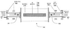
도 5a는 제1 실시예에 따른 이온 소스(300)를 나타내는 도면이다. 도 3에 도시된 것과 같은 2 개의 ICP 플라즈마 소스들(301, 302)이 확산 챔버(210)와 축 방향으로 결합된다. 확산 챔버(210)는 바람직하게는 실린더 형태를 가지며, 바람직하게는 유전 실린더들(301, 302)의 지름보다 큰 지름, 예를 들면 20-50cm의 지름을 갖는다. 상기 ICP 소소들 및 상기 확산 챔버는 중심 축들이 공통 직선 상에 있도록 정렬된다. 즉, 3개의 구성물들이 동축을 갖는다. 추출 개구(230)는 확산 챔버(210) 상에 배치되며, 상기 챔버의 중심 축에 평행하다. 상기 추출 개구의 높이는 바람직하게는 3-5mm 정도로 작을 수 있다. 확산 챔버(210)의 길이는 35cm의 폭을 갖는 리본 이온 빔 추출 슬릿(230)을 수용할 수 있도록 선택될 수 있으며, 이는 300mm 지름의 웨이퍼들의 이온 주입을 가능하게 할 수 있다. 상기 확산 챔버의 길이에 제한 조건은 없으므로, 차세대 450mm 직경 웨이퍼의 이온 주입을 허용하는 50cm의 넓은 추출 개구도 가능하다.5A is a view showing the
도 5b는 제2 실시예에 따른 플라즈마 이온 소스(300)를 나타내는 도면이다. 콘쥬게이티드된 ICP 소스들 대신, 도 4에 도시된 바와 같은 2 개의 ECR 플라즈마 소스들(301, 302)이 확산 챔버(210)와 축방향으로 결합된다.5B is a view showing a
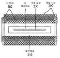
도 6a는 확산 챔버의 측면도이며, 도 6b는 도 5a 및 도 5b에 도시된 실시예들과 함께 사용될 수 있는 확산 챔버의 단면도이다. 도 6b에 도시된 바와 같이, 확산 챔버(210)의 챔버 하우징(240) 바람직하게는 알루미늄 혹은 이와 유사한 자성이 침투가능한 물질들로 설계된다. 특정 실시예들에 있어서, 전기 전도성 라이너(245)가 상기 챔버 하우징의 내부 표면 주변에 배치된다. 이러한 라이너(245)는 바람직하게는 도핑된 실리콘 카바이드(carbide) 혹은 흑연으로 구성되며 두 가지 목적을 갖는다. 첫째로, 플라즈마(260) 및 이로부터 발생하는 이온 빔(270)에 대한 챔버 벽(240)으로부터의 금속들에 의한 스퍼터링 및 오염을 감소시키는 기능을 한다. 두 번째로, 이의 도전성 성질은 플라즈마 포텐셜의 컨트롤을 가능케한다.FIG. 6A is a side view of the diffusion chamber, and FIG. 6B is a cross-sectional view of a diffusion chamber that can be used with the embodiments shown in FIGS. 5A and 5B. As shown in FIG. 6B, the
양이온들의 추출을 가능케 하기 위해, 상기 챔버는 고 전압 DC 파워 서플라이(도시되지 않음)에 의해 양의 포텐셜로 전기적으로 편향된다. 일 실시예에 있어서, 도 6a 및 도 6b에 도시된 바와 같이, 단일 추출 개구가 추출 광학 기구(250)에 의해 빔을 추출하도록 사용될 수 있다. 전형적으로, 추출 광학 기구(250)는 다양한 전기적 포텐셜을 갖는 전극들의 세트를 포함하며, 이는 플라즈마(260)로부터 양이온들을 추출하도록 제공된다. 도 6b는 3극 추출 광학 기구를 도시하고 있으나, 4극 혹은 5극 조합도 가능하다. 일 실시예에 있어서, 상기의 개구는 3mm의 높이, 350mm의 길이를 가질 수 있으며, 다른 사이즈들 및 구조들 역시 가능하다. 제2 실시예에 따르면, 도 6c에 도시된 바와 같이, 복수의 평행 개구들이 사용되어 추가로 포함되는 복수의 빔렛(beamlet, 275)들의 추출을 가능케 하며, 더 길고 높은 전류의 리본 이온 빔(270)을 발생시킬 수 있다.To enable extraction of the cations, the chamber is electrically deflected to a positive potential by a high voltage DC power supply (not shown). In one embodiment, as shown in FIGS. 6A and 6B, a single extraction aperture may be used to extract the beam by the
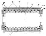
도 6a에 도시된 바와 같이, 플라즈마(260)의 균일도를 향상시키기 위해, 바람직하게는 Sm-Co 또는 Nb-Fe-B와 같은 영구 자석 바들(280)의 열들에 의해 구현되며, 상기 확산 챔버의 길이 방향으로 배향되는 멀티커스프(multicusp) 자성 구조가 사용될 수 있다. 이러한 자석들(280)은 확산 챔버(210)의 챔버 하우징(240)의 외부 표면을 대향하는 극들이 극성에 있어 교대로 배열되도록 장착된다. 즉, 하나의 자석 열은 N극이 챔버 하우징(240)을 대향하며, 상기 열에 각 측부에 인접한 열들의 자석들은 S극이 상기 챔버 하우징을 향하도록 배열된다. 이러한 패턴은 추출 개구(230)에 인접한 영역을 제외하고 상기 챔버 하우징의 둘레 주위에서 반복된다. 가능한 한 많은 자기력선들(285)을 수용하기 위해, 상기 확산 챔버 벽들의 좌측 및 우측 상에서는, 자석들(280)을 연속적으로 그리고 도 6c에 도시된 바와 같이 방사상 패턴을 형성할 수 있는 종방향 열들의 동일한 극성으로 배치시킴으로써 멀티커스프 장이 발생될 수 있다. 플라즈마 내의 자기장 강도(B) 및 자기력선들(285)의 투과 깊이(y)는 하기의 식에 따라, 교대로 배열되는 극성을 갖는 자석들의 둘레방향 분리(d), 자석 표면에서의 자기장 강도(B0) 및 자석들의 폭(Δ)에 의해 조절된다.Is implemented by rows of permanent magnet bars 280, preferably Sm-Co or Nb-Fe-B, to improve the uniformity of the

상기의 변수들의 적절한 조절에 의해, 강한 자기장이 상기 챔버 벽 주위에서 생성될 수 있으며, 한편 벌크 플라즈마는 자기장으로부터 자유롭다. 이러한 방식으로, 전하 입자들(전자들 혹은 이온들)은 자기력선들(285)에 트랩되고, 따라서 챔버 벽(240)으로의 손실이 감소되고 명백히 높은 플라즈마 밀도 및 균일도를 얻을 수 있다. 자기장의 강도는 상기 자석들을 둘러싸며, 요크(yoke) 효과를 일으키는 강철 시트(290)를 부가함으로써 증가될 수 있다. 일 실시예에 있어서, Δ=3/8, d=3/4, 자기장 강도는 1.5 에서 50G인 사각형 단면 형상의 Sm-Co 자석들이 상기 챔버 벽으로부터 수득되었다. 제안된 기하형태에서, 얻어지는 전체 멀티커스프 자기장은 플라즈마(260)를 추출 개구(230) 쪽으로 이동시켰다. 상기 추출 개구 영역에서는 자기장이 없으므로, 상기 전하 입자들은 자유롭게 추출 개구(230)를 향해 이동하며, 따라서 고밀도의 이온 빔이 추출될 수 있다. 도 6b 및 도 6c에 점선으로 도시된 바와 같이, 상기 벌크의 자기장으로부터 자유로운 플라즈마 및 강한 자기장이 존재하는 영역들 사이의 경계가 표시된다.By proper adjustment of the above parameters, a strong magnetic field can be generated around the chamber wall, while the bulk plasma is free from magnetic fields. In this way, the charge particles (electrons or ions) are trapped in the
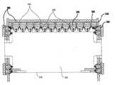
도 7a 내지 도 7d에 도시된 또 다른 실시예에 있어서, 멀티커스프 자기장(285)을 발생시키는 영구 자석 바들(280)이 둘레 방향 패턴으로 배열된다. 즉, 동일한 극성, 예를 들면, N극이 챔버의 내부를 향하는 자석들의 열들이 상기 추출 개구가 위치하는 원형 부위를 제외한 상기 챔버의 둘레를 따라 배치된다. 상기 멀티커스프 자기장은 교대로 배열되는 극성의 자석들을 사용하여 발생된다. 즉, 종방향 길이(d)로 분리되는 인접한 원주방향 열들은 상기 챔버의 내부를 향하는 S극을 가지며, 상기 챔버의 외부를 향하는 N극을 갖는다. 상기의 패턴은 도 7d에 도시된 바와 같이 동심 원들을 따라 교대로 배열되는 극성을 갖는 자석들을 배치시킴으로써 좌측 및 우측 벽에서 지속된다. 작동시 발생하는 열로부터 상기 자석들을 보호하기 위해, 냉각 시스템(295, 도 7b 및 도 7c 참조)이 상기 확산 챔버 주위로 배치될 수 있다. 물이 냉각제로 사용될 수 있으나, 다른 냉각 액체 및 가스들도 사용 가능하다.7A-7D, the permanent magnet bars 280 generating the multicurrency
도 6 내지 도 7은 멀티커스프 자기장을 발생시키는데 사용되는 두 대표적인 구조들을 도시하고 있다. 두 실시예들에 있어서, 원하지 않은 자기장 효과로부터 빔을 보호하기 위해, 상기 이온 빔 추출 영역 및 벌크 플라즈마는 자기장으로부터 자유롭다. 즉, 상기 멀티커스프 자기장은 상기 추출 개구가 위치하는 원형 부위를 제외한 상기 확산 챔버의 둘레방향을 따라 연장한다. 당해 기술분야에서 통상의 지식을 가진 자라면 다른 기술들 혹은 구성들 역시 본 발명의 목적을 달성하기 위해 채용될 수 있음을 이해할 것이다.Figures 6-7 illustrate two representative structures used to generate the multicurse magnetic field. In both embodiments, to protect the beam from unwanted magnetic field effects, the ion beam extraction region and the bulk plasma are free of magnetic fields. That is, the multicurse magnetic field extends along the circumferential direction of the diffusion chamber except for the circular portion where the extraction opening is located. Those of ordinary skill in the art will appreciate that other techniques or configurations may be employed to achieve the objects of the invention.
도 4a 및 도 4b를 참조하면, ECR 플라즈마 소스들(301, 302)은 플라즈마를 공통 확산 챔버로 주입한다. 각 ECR 플라즈마 소스의 축 방향 자기장은 서로 반대방향이기 때문에, 각 솔레노이드로부터 발생하는 자기장은 개구(230)를 통한 이온 추출이 교란되지 않도록 충분히 낮은 값으로 감소되는 것이 필수적이다. 이는 부분적으로 상기 확산 챔버에 대한 솔레노이드의 적절한 배치에 의해, 그리고 좌측 및 우측 확산 챔버 플랜지들의 멀티커스프 자기장들에 의해 구현될 수 있다. 국부적 멀티커스프 자기장의 강도가 상대적으로 높을 수 있기 때문에, 상기 확산 챔버 내의 솔레노이드들에 의해 발생하는 상기 자기장의 약한 축 방향 성분은 상쇄될 수 있다. 수득되는 도 8a에 도시된 축 방향 자기장 프로파일은 각 소스의 ECR 조건을 충족시키는 필요한 자기장 강도를 제공할 수 있으며, 동시에 상기 확산 챔버의 벌크 내의 대략 0에 가까운 축 방향 자기장을 생성하여 상기 멀티커스프 장이 플라즈마를 벽으로부터 밀어내며 동시에 상기 추출 개구로 인도할 수 있도록 한다.Referring to Figures 4A and 4B,
도 8b는 다양한 구조들에 있어서 플라즈마 밀도를 나타내는 그래프이다. "PS1" 및 "PS2"로 표시된 라인들은 오직 하나의 플라즈마 소스(ICP 혹은 ECR)가 플라즈마를 상기 확산 챔버 내부로 주입하는 경우에 있어서 축방향 위치의 함수로서의 플라즈마 밀도의 관계를 나타낸다. 상기 밀도가 플라즈마 소스(100)로부터의 축방향 거리가 증가할수록 감소하는 것을 알 수 있다. "PS1+PS2"로 표시된 라인은 두 플라즈마 소스들이 작동하는 구조에서 플라즈마 밀도를 나타내는 그래프이다. 즉, 공통 확산 챔버에서 플라즈마를 펌핑하나 상기 확산 챔버에는 멀티커스프 자기장이 존재하지 않는다. 개별 플라즈마 소스들로부터의 밀도들은 보강되어 상기 확산 챔버의 축방향을 따라 보다 균일한 플라즈마 밀도를 생성함을 알 수 있다. 이러한 방식으로, 제1 소스(301)로부터의 거리가 증가됨에 따라 확산 챔버(210) 내에서 발생하는 플라즈마 밀도의 감소는 제2 플라즈마 소스(302)의 존재에 의해 억제될 수 있다. "PS1+PS2+MM"으로 표시되는 라인은 두 플라즈마 소스들이 작동하며 멀티커스프 자기장이 존재하는 구조에 있어서 플라즈마 밀도의 프로파일을 나타낸다. 상기 멀티커스프 자기장의 존재는 플라즈마 균일성의 종방향 영역을 연장시킨다.8B is a graph showing the plasma density in various structures. The lines labeled "PS1" and "PS2 " represent the relationship of plasma density as a function of axial position when only one plasma source (ICP or ECR) injects the plasma into the diffusion chamber. It can be seen that the density decreases as the axial distance from the
두 플라즈마 소스들(ICP 혹은 ECR)을 활용하는 예를 바람직한 실시예들로 설명하였으나, 본 출원은 확산 챔버와 결합된 단일 플라즈마 소스의 사용도 포함한다. 이러한 실시예에 있어서, 확산 챔버 내부에서 종방향 축을 따라 더 깊은 위치로 갈수록 감소되는 플라즈마 밀도로부터 초래되는 비균일한 빔 프로파일은 가변적인 높이(플라즈마 밀도 감소 방향으로 점진적으로 증가하는)를 갖는 추출 슬릿의 사용 및/또는 확산 챔버 내의 멀티커스프 자기장 구조 내의 자기장 구배의 도입과 같은 다른 기술들을 통해 억제될 수 있다.Although an example utilizing both plasma sources (ICP or ECR) has been described in the preferred embodiments, the present application also includes the use of a single plasma source coupled with a diffusion chamber. In this embodiment, the non-uniform beam profile resulting from the plasma density decreasing from the plasma density to the deeper along the longitudinal axis within the diffusion chamber has an extraction slit (which gradually increases in the plasma density decreasing direction) And / or the introduction of a magnetic field gradient in the multi-cushion magnetic field structure in the diffusion chamber.
상술한 두가지 타입의 이온 소스들은 확산 챔버 내에서 얻어지는 플라즈마 밀도가 다양한 방법으로 변화될 수 있도록 한다. 두 실시예들에 있어서, 각 플라즈마 소스는 독립적으로 작동 가스가 공급되며, 진공 펌핑이 공통 확산 챔버 상의 추출 개구를 통해 수행되므로, 각 플라즈마 소스 내부로의 가스 유량을 독립적으로 변화시킬 수 있다. 이는 종방향을 따라 플라즈마 밀도 프로파일의 미세 조절을 가능케 한다.The two types of ion sources described above allow the plasma density obtained in the diffusion chamber to be varied in various ways. In both embodiments, each plasma source is independently supplied with working gas, and since the vacuum pumping is performed through the extraction opening on the common diffusion chamber, the gas flow rate into each plasma source can be independently varied. This allows fine tuning of the plasma density profile along the longitudinal direction.
추가적으로, 상기 확산 챔버 내의 상기 멀티커스프 자기장은 플라즈마 밀도의 균일성을 향상시키기 위해 조절될 수 있다. 이는 표면 자기장 강도, 자석 바들의 치수 및 분리 갭들의 적절한 값들을 선택함으로써 가능하다.Additionally, the multicurse magnetic field in the diffusion chamber may be adjusted to improve the uniformity of the plasma density. This is possible by selecting the appropriate values of the surface magnetic field strength, the dimensions of the magnet bars and the separation gaps.
ICP 소스들의 경우, RF 안테나를 구동하는데 사용되는 파워가 각 소스들 각각에 독립적으로 변화될 수 있으며, 따라서 또 다른 조절 변수를 도입할 수 있다. 유사하게, ECR 소스들에 있어서, 주입된 마이크로웨이브 파워가 독립적으로 변화될 수 있다.For ICP sources, the power used to drive the RF antenna can be varied independently for each of the sources, thus introducing another tuning variable. Similarly, for ECR sources, the injected microwave power can be varied independently.
ECR 소스들의 경우, 플라즈마 밀도의 축 방향 프로파일을 조절하고 이에 따라 빔의 균일성을 조절하는 추가적인 방법은 DC 전류(솔레노이드가 사용되는 경우)를 변형시키거나 혹은 공간 위치(영구 자석들이 사용되는 경우)를 조절하여 각 플라즈마 소스 내의 자기장을 형상화하는 것이다.For ECR sources, an additional way to adjust the axial profile of the plasma density and thus the uniformity of the beam is to modify the DC current (if a solenoid is used) or to adjust the spatial position (if permanent magnets are used) To shape the magnetic field in each plasma source.
각 조절 노브의 미세 조절은 연장된 너비에서 매우 우수한 균일성을 갖는 높은 리본 이온 빔 전류의 추출을 가능케 할 수 있다. 이는 넓은 직경의 웨이퍼들에 균일한 도오즈의 이온 주입을 가능케 할 수 있다.The fine adjustment of each adjustment knob can enable the extraction of high ribbon ion beam currents with very good uniformity at extended widths. This allows uniform ion implantation of ions into wide diameter wafers.
상술한 바와 같이, 본 발명의 장치는 이온 주입기에 사용될 수 있다. 350에서 500mm 까지의 너비를 갖는 수백 밀리앰프(miliamp)의 균일한 리본 이온 빔들이 본 이온 소스를 이용하여 생성될 수 있다.As described above, the apparatus of the present invention can be used in an ion implanter. Uniform ribbon ion beams of several hundred milliamperes (mm) with a width of 350 to 500 mm can be generated using the present ion source.
그러나, 이의 용도는 통상적인 이온 주입 장치에 국한되지 않는다. 본 장치는 다른 장치들, 예를 들면 도 9에 도시된 바와 같이 온-웨이퍼 빌드 솔라 셀(on-wafer build solar cell)들을 도핑하는 장치에 사용될 수 있다. 요구되는 추출 전류가 매우 크기 때문에, 원하는 도핑은 바람직하게는 단일 패스 내에서 구현될 수 있다. 이와 같은 경우, 웨이퍼들(510)은 컨베이어 벨트(520)와 같은 표면 상에 위치되며, 이는 리본 이온 빔(270)이 입사되도록 웨이퍼들(510)을 이동시킨다. 일 실시예에 있어서, 로봇 암(500)이 컨베이어 벨트(520) 상에 웨이퍼들(510)을 위치시키는데 사용될 수 있다. 이와 같은 실시예에 있어서, 원하는 도오즈가 빔 전류 및 컨베이어 벨트(520)의 속도에 의해 셋팅된다. 이온 주입 후에, 웨이퍼들(510)은 벨트(520)로부터, 예를 들면 제2 로봇 암(530)에 의해 취출된다.However, its use is not limited to conventional ion implantation apparatuses. The device may be used in other devices, for example devices that dope on-wafer build solar cells as shown in FIG. Because the required extraction current is very large, the desired doping can preferably be implemented in a single pass. In such a case, the
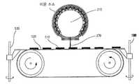
유사한 방법으로, 도 10에 도시된 바와 같이, 솔라 셀 박(400)이 도핑될 수 있다. 전술한 이온 빔 소스를 이용하여, 모터 구동 릴들(410, 420) 상에 감싸진 박(400)은 연속적으로 빔 경로와 교차하는 진공 챔버를 통과할 수 있다. 높은 빔 전류는 원하는 도핑이 바람직하게는 단일 패스에서 신속히 구현될 수 있도록 할 수 있다. 이 때, 도오즈는 상기 빔 전류 및 릴의 회전 속도에 의해 셋팅될 수 있다. 도 10은 이러한 공정을 개략적으로 나타낸다. 이온 빔(270)이 방출되는 챔버 하우징 및 확산 챔버의 단면도가 도시되었다. 상기 이온 소스의 다른 구성들은 명확화를 위해 도면에서 의도적으로 생략되었으나, 본 구조에 존재할 수 있다. 상기 이온 빔은 리본 형상이며, 도 10의 평면에 직교하는 긴 치수를 갖는다. 일 실시예에 있어서, 상기 솔라 셀 박은 방출된 이온 빔의 너비와 동일하거나 약간 작은 너비를 가질 수 있다. 상기 이온 빔은 확산 챔버(210)의 추출 개구 아래로 통과할 때, 솔라 셀 박(400)의 일부에 충돌할 수 있다. 일 실시예에 있어서, 솔라 셀 박(400)은 회전 릴들(410, 420)을 통해 이송될 수 있다. 이러한 릴들의 속도는 박(400)의 각 부분들이 상기 이온 빔에 노출되는 시간의 양을 변화시키기 위해 조절될 수 있다.In a similar manner, as shown in FIG. 10, the
본 발명의 실시예들에 따르면, 일 이상의 플라즈마 소스를 활용하여 높은 밀도의 넓은 리본 이온 빔을 생성할 수 있다.According to embodiments of the present invention, one or more plasma sources may be utilized to produce a high density of broad ribbon ion beams.
특정한 실시예들을 참조로 본 발명에 대해 설명하였으나, 당해 기술 분야에 통상의 지식을 가진 자라면 첨부된 청구항들에 의해 정의되는 본 발명의 사상 및 범위로부터 벗어나지 않고 다양한 변경이 가능함을 이해하여야 한다.Although the present invention has been described with reference to particular embodiments, it is to be understood that various changes may be made therein without departing from the spirit and scope of the invention as defined by the appended claims.
1: 파워 서플라이2: 플라즈마 소스
4: 전극6: 질량 분석 자석
8: 감속 스테이지10: 교정 자석
14: 웨이퍼 지지체16: 패러데이 컵
100: ICP 플라즈마 소스101, 151: 작동 가스
105: 안테나110: 유전 실린더
115, 165: 플랜지120: RF 파워 서플라이
125: 매칭 네트워크130, 170: 가스 유입구
135, 180: 탄성 커플링150: ECR 플라즈마 소스
155: 실린더160: 자석
168: 유전 윈도우210: 확산챔버
230: 추출 개구240: 챔버 하우징
245: 라이너250: 추출 광학 기구
260: 플라즈마270: 이온 빔
280: 자석 바285: 자기력 선
290: 강철 시트295: 냉각 라인
300: 이온 소스400: 솔라 셀 박
410, 420: 회전 릴500: 로봇 암
510: 웨이퍼520: 컨베이어 벨트
530: 제2 로봇 암1: Power supply 2: Plasma source
4: Electrode 6: Mass analyzing magnet
8: Deceleration stage 10: Calibration magnet
14: Wafer support 16: Faraday cup
100: ICP plasma source 101, 151: working gas
105: antenna 110: oil-filled cylinder
115, 165: Flange 120: RF power supply
125: matching
135, 180: Elastic coupling 150: ECR plasma source
155: cylinder 160: magnet
168: dielectric window 210: diffusion chamber
230: extraction opening 240: chamber housing
245: liner 250: extraction optics
260: Plasma 270: ion beam
280: magnetic bar 285: magnetic line
290: steel sheet 295: cooling line
300: ion source 400: solar cell foil
410, 420: Rotary reel 500: Robot arm
510: Wafer 520: Conveyor belt
530: Second robot arm
Claims (17)
Translated fromKorean상기 제1 유전 실린더 내부로 제1 가스를 제공하도록 상기 제1 유전 실린더와 연통하는 제1 가스 유입구; 및
상기 제1 가스에 RF 파워를 유도 결합시키도록 상기 제1 유전 실린더를 감싸는 제1 안테나를 포함하는 것을 특징으로 하는 제1 유도 결합 플라즈마(ICP) 소스;
제2 중심축, 제2 폐쇄 단부 및 제2 개방 단부를 갖는 제2 유전 실린더;
상기 제2 유전 실린더 내부로 제2 가스를 제공하도록 상기 제2 유전 실린더와 연통하는 제2 가스 유입구; 및
상기 제2 가스에 RF 파워를 유도 결합시키도록 상기 제2 유전 실린더를 감싸는 제2 안테나를 포함하는 것을 특징으로 하는 제2 유도 결합 플라즈마(ICP) 소스; 및
제1 단부 및 제2 단부를 포함하는 확산 챔버를 정의하는 챔버 하우징을 포함하며,
상기 확산 챔버의 상기 제1 단부는 상기 제1 유전 실린더의 상기 개방 단부와 연통하며, 상기 확산 챔버의 상기 제2 단부는 상기 제2 유전 실린더의 상기 개방 단부 및 추출 개구와 연통하고,
상기 추출 개구는 제1 길이 및 제2 길이를 가지고, 상기 제1 길이는 상기 제2 길이보다 크며, 상기 제1 길이는 상기 제1 유전 실린더의 상기 제1 중심축과 평행한 것을 특징으로 하는 이온 소스.A first dielectric cylinder having a first central axis, a first closed end and a first open end;
A first gas inlet communicating with the first dielectric cylinder to provide a first gas into the first dielectric cylinder; And
A first inductively coupled plasma (ICP) source comprising: a first antenna surrounding the first dielectric cylinder to inductively couple RF power to the first gas;
A second dielectric cylinder having a second central axis, a second closed end and a second open end;
A second gas inlet communicating with the second dielectric cylinder to provide a second gas into the second dielectric cylinder; And
A second inductively coupled plasma (ICP) source comprising: a second antenna surrounding the second dielectric cylinder to inductively couple RF power to the second gas; And
A chamber housing defining a diffusion chamber including a first end and a second end,
Wherein the first end of the diffusion chamber is in communication with the open end of the first dielectric cylinder and the second end of the diffusion chamber is in communication with the open end of the second dielectric cylinder and the extraction opening,
Characterized in that the extraction opening has a first length and a second length, the first length being greater than the second length, and the first length being parallel to the first central axis of the first dielectric cylinder sauce.
상기 제1 실린더 내부로 제1 가스를 제공하도록 상기 제1 실린더와 연통하는 제1 가스 유입구;
상기 제1 실린더를 감싸며 상기 제1 실린더 내부에서 제1 축방향 자기장을 생성하는 제1 자석; 및
상기 제1 실린더 내부로 상기 제1 축방향 자기장과 결합하여 상기 제1 가스를 이온화하는 제1 마이크로웨이브를 도입하기 위해 상기 제1 폐쇄 단부에 인접하게 배치되는 제1 유전 윈도우를 포함하는 것을 특징으로 하는 제1 전자 사이클로트론 공명(ECR) 플라즈마 소스;
제2 중심축, 제2 폐쇄 단부 및 제2 개방 단부를 갖는 제2 실린더;
상기 제2 실린더 내부로 제2 가스를 제공하도록 상기 제2 실린더와 연통하는 제2 가스 유입구;
상기 제2 실린더를 감싸며 상기 제2 실린더 내부에서 제2 축방향 자기장을 생성하는 제2 자석; 및
상기 제2 실린더 내부로 상기 제2 축방향 자기장과 결합하여 상기 제2 가스를 이온화하는 제2 마이크로웨이브를 도입하기 위해 상기 제2 폐쇄 단부에 인접하게 배치되는 제2 유전 윈도우를 포함하는 것을 특징으로 하는 제2 ECR 플라즈마 소스; 및
제1 단부 및 제2 단부를 포함하는 확산 챔버를 정의하는 챔버 하우징을 포함하며,
상기 확산 챔버의 상기 제1 단부는 상기 제1 실린더의 상기 개방 단부와 연통하며, 상기 확산 챔버의 상기 제2 단부는 상기 제2 실린더의 상기 개방 단부 및 추출 개구와 연통하고,
상기 추출 개구는 제1 길이 및 제2 길이를 가지고, 상기 제1 길이는 상기 제2 길이보다 크며, 상기 제1 길이는 상기 제1 실린더의 상기 제1 중심축과 평행한 것을 특징으로 하는 이온 소스.A first cylinder having a first central axis, a first closed end and a first open end;
A first gas inlet communicating with the first cylinder to provide a first gas into the first cylinder;
A first magnet surrounding the first cylinder and generating a first axial magnetic field inside the first cylinder; And
And a first dielectric window disposed adjacent the first closed end for introducing a first microwave into the first cylinder in association with the first axial magnetic field to ionize the first gas. A first electron cyclotron resonance (ECR) plasma source;
A second cylinder having a second central axis, a second closed end, and a second open end;
A second gas inlet communicating with the second cylinder to provide a second gas into the second cylinder;
A second magnet surrounding the second cylinder and generating a second axial magnetic field within the second cylinder; And
And a second dielectric window disposed adjacent the second closed end for introducing a second microwave into the second cylinder in association with the second axial magnetic field to ionize the second gas. A second ECR plasma source; And
A chamber housing defining a diffusion chamber including a first end and a second end,
The first end of the diffusion chamber communicates with the open end of the first cylinder and the second end of the diffusion chamber communicates with the open end of the second cylinder and the extraction opening,
The extraction opening having a first length and a second length, the first length being greater than the second length, and the first length being parallel to the first central axis of the first cylinder. .
상기 제1 실린더 내부로 제1 가스를 제공하도록 상기 제1 실린더와 연통하는 제1 가스 유입구; 및
상기 제1 가스를 플라즈마로 이온화하는 제1 부재를 포함하는 ICP 플라즈마 소스 및 ECR 플라즈마 소스로 구성된 그룹에서 선택된 제1 플라즈마 소스;
제2 중심축, 제2 폐쇄 단부 및 제2 개방 단부를 갖는 제2 실린더;
상기 제2 실린더 내부로 제2 가스를 제공하도록 상기 제2 실린더와 연통하는 제2 가스 유입구; 및
상기 제2 가스를 플라즈마로 이온화하는 제2 부재를 포함하는 ICP 플라즈마 소스 및 ECR 플라즈마 소스로 구성된 그룹에서 선택된 제2 플라즈마 소스; 및
제1 단부 및 제2 단부를 포함하는 확산 챔버를 정의하는 챔버 하우징을 포함하고, 상기 확산 챔버의 상기 제1 단부는 상기 제1 실린더의 상기 개방 단부와 연통하며, 상기 확산 챔버의 상기 제2 단부는 상기 제2 실린더의 상기 개방 단부 및 추출 개구와 연통하고, 상기 추출 개구는 제1 길이 및 제2 길이를 가지고, 상기 제1 길이는 상기 제2 길이보다 크며, 상기 제1 길이는 상기 제1 실린더의 상기 제1 중심축과 평행한 것을 특징으로 하는 이온 소스를 제공하는 단계; 및
상기 이온 소스의 특성을 조절하는 단계를 포함하며, 상기 특성은 상기 제1 및 제2 가스를 이온화하는 상기 부재와 연관된 변수 및 상기 제1 및 제2 가스 유입구로의 상기 제1 및 제2 가스의 유량으로 구성된 그룹에서 선택되는 것을 특징으로 하는 이온 빔 균일도의 조절 방법.A first cylinder having a first central axis, a first closed end and a first open end;
A first gas inlet communicating with the first cylinder to provide a first gas into the first cylinder; And
A first plasma source selected from the group consisting of an ICP plasma source and an ECR plasma source comprising a first member for ionizing the first gas to a plasma;
A second cylinder having a second central axis, a second closed end, and a second open end;
A second gas inlet communicating with the second cylinder to provide a second gas into the second cylinder; And
A second plasma source selected from the group consisting of an ICP plasma source and an ECR plasma source comprising a second member for ionizing the second gas to a plasma; And
A first end of the diffusion chamber communicating with the open end of the first cylinder and a second end of the diffusion chamber communicating with the second end of the diffusion chamber, The extraction opening communicating with the open end of the second cylinder and the extraction opening, the extraction opening having a first length and a second length, the first length being greater than the second length, The ion source being parallel to the first central axis of the cylinder; And
Wherein the characteristics include a parameter associated with the member for ionizing the first and second gases and a parameter associated with the first and second gases to the first and second gas inflows, And a flow rate of the ion beam.
제1 RF 파워 서플라이와 연통하는 제1 안테나로 상기 제1 실린더를 감싸는 단계
제2 RF 파워 서플라이와 연통하는 제2 안테나로 상기 제2 실린더를 감싸는 단계; 및
상기 RF 파워 서플라이들을 작동시켜 상기 각 안테나들에 파워를 공급하는 단계를 포함하며, 상기 제1 및 제2 가스를 이온화하는 상기 부재들과 연관된 변수는 상기 RF 파워 서플라이들의 출력을 포함하는 것을 특징으로 하는 이온 빔 균일도의 조절 방법.14. The method of claim 13 wherein the plasma sources comprise an ICP plasma source and ionizing the gas by the first and second members,
Wrapping the first cylinder with a first antenna in communication with a first RF power supply,
Wrapping the second cylinder with a second antenna in communication with a second RF power supply; And
And operating the RF power supplies to power each of the antennas, wherein variables associated with the members for ionizing the first and second gases include an output of the RF power supplies A method of adjusting the uniformity of the ion beam.
상기 제1 실린더를 제1 솔레노이드로 감싸는 단계;
상기 제2 실린더를 제2 솔레노이드로 감싸는 단계;
전자기파를 상기 제1 및 제2 실린더들 내부에 도입하는 단계; 및
DC 전류 서플라이를 작동시켜 상기 솔레노이드들에 의해 생성되는 자기장 프로파일을 컨트롤하는 단계를 포함하며, 상기 제1 및 제2 가스를 이온화하는 상기 부재들과 연관된 변수는 상기 솔레노이드에 흐르는 전류를 포함하는 것을 특징으로 하는 이온 빔 균일도의 조절 방법.14. The method of claim 13, wherein the plasma sources include an ECR plasma source, and ionizing the gas by the first and second members,
Wrapping the first cylinder with a first solenoid;
Wrapping the second cylinder with a second solenoid;
Introducing an electromagnetic wave into the first and second cylinders; And
Operating a DC current supply to control a magnetic field profile generated by the solenoids, wherein a variable associated with the members for ionizing the first and second gases comprises a current flowing in the solenoid Of the ion beam.
제1 영구 자석으로 상기 제1 실린더를 감싸는 단계;
제2 영구 자석으로 상기 제2 실린더를 감싸는 단계; 및
전자기파를 상기 제1 및 제2 실린더들 내부에 도입하는 단계를 포함하며,
상기 제1 및 제2 가스를 이온화하는 상기 부재들과 연관된 변수는 상기 영구 자석들의 축 방향 위치를 포함하는 것을 특징으로 하는 이온 빔 균일도의 조절 방법.14. The method of claim 13, wherein the plasma sources include an ECR plasma source, and ionizing the gas by the first and second members,
Wrapping the first cylinder with a first permanent magnet;
Wrapping the second cylinder with a second permanent magnet; And
Introducing an electromagnetic wave into the first and second cylinders,
Wherein variables associated with said members for ionizing said first and second gases comprise an axial position of said permanent magnets.
상기 제1 폐쇄 단부 상의 제1 유전 윈도우를 통해 상기 제1 실린더 내부로 마이크로웨이브를 주입하는 단계; 및
상기 제2 폐쇄 단부 상의 제2 유전 윈도우를 통해 상기 제2 실린더 내부로 마이크로웨이브를 주입하는 단계를 포함하며,
상기 제1 및 제2 가스를 이온화하는 상기 부재들과 연관된 변수는 상기 제1 및 제2 실린더들 내부로 주입되는 상기 마이크로웨이브의 파워를 포함하는 것을 특징으로 하는 이온 빔 균일도의 조절 방법.14. The method of claim 13, wherein the plasma sources include an ECR plasma source, and ionizing the gas by the first and second members,
Injecting a microwave into the first cylinder through a first dielectric window on the first closed end; And
Injecting a microwave into the second cylinder through a second dielectric window on the second closed end,
Wherein variables associated with the members for ionizing the first and second gases comprise power of the microwave injected into the first and second cylinders.
Applications Claiming Priority (2)
| Application Number | Priority Date | Filing Date | Title |
|---|---|---|---|
| US12/424,964 | 2009-04-16 | ||
| US12/424,964US7999479B2 (en) | 2009-04-16 | 2009-04-16 | Conjugated ICP and ECR plasma sources for wide ribbon ion beam generation and control |
Publications (2)
| Publication Number | Publication Date |
|---|---|
| KR20120005026A KR20120005026A (en) | 2012-01-13 |
| KR101647314B1true KR101647314B1 (en) | 2016-08-10 |
Family
ID=42980308
Family Applications (1)
| Application Number | Title | Priority Date | Filing Date |
|---|---|---|---|
| KR1020117026703AActiveKR101647314B1 (en) | 2009-04-16 | 2010-04-01 | Conjugated icp and ecr plasma sources for wide ribbon ion beam generation and control |
Country Status (6)
| Country | Link |
|---|---|
| US (1) | US7999479B2 (en) |
| JP (1) | JP5767627B2 (en) |
| KR (1) | KR101647314B1 (en) |
| CN (1) | CN102449739B (en) |
| TW (1) | TWI467615B (en) |
| WO (1) | WO2010120569A2 (en) |
Families Citing this family (18)
| Publication number | Priority date | Publication date | Assignee | Title |
|---|---|---|---|---|
| US8142607B2 (en)* | 2008-08-28 | 2012-03-27 | Varian Semiconductor Equipment Associates, Inc. | High density helicon plasma source for wide ribbon ion beam generation |
| US20100074808A1 (en)* | 2008-09-23 | 2010-03-25 | Sang Hun Lee | Plasma generating system |
| CN102598201A (en)* | 2009-08-27 | 2012-07-18 | 摩赛科结晶公司 | Penetrating plasma generating apparatus for high vacuum chambers |
| US20110108058A1 (en)* | 2009-11-11 | 2011-05-12 | Axcelis Technologies, Inc. | Method and apparatus for cleaning residue from an ion source component |
| JP5813536B2 (en)* | 2012-03-02 | 2015-11-17 | 株式会社東芝 | Ion source |
| JP5822767B2 (en)* | 2012-03-22 | 2015-11-24 | 住友重機械イオンテクノロジー株式会社 | Ion source apparatus and ion beam generating method |
| US8809803B2 (en)* | 2012-08-13 | 2014-08-19 | Varian Semiconductor Equipment Associates, Inc. | Inductively coupled plasma ion source with multiple antennas for wide ion beam |
| KR101403323B1 (en)* | 2013-01-04 | 2014-06-05 | 한국과학기술원 | Oscillator and forming method of the same |
| US8669538B1 (en)* | 2013-03-12 | 2014-03-11 | Varian Semiconductor Equipment Associates, Inc. | Method of improving ion beam quality in an implant system |
| FR3019708B1 (en)* | 2014-04-04 | 2016-05-06 | Hydromecanique & Frottement | CIPO - Patent |
| CN105590823B (en)* | 2014-10-22 | 2019-07-05 | 上海凯世通半导体股份有限公司 | RF ion source device |
| JP6642612B2 (en)* | 2018-04-12 | 2020-02-05 | 日新イオン機器株式会社 | Ion source, ion beam irradiation device, and method of operating ion source |
| US11069511B2 (en)* | 2018-06-22 | 2021-07-20 | Varian Semiconductor Equipment Associates, Inc. | System and methods using an inline surface engineering source |
| CN109411319A (en)* | 2018-11-16 | 2019-03-01 | 合肥飞帆等离子科技有限公司 | A kind of novel plasma cathode electronics electron gun and 3D printer |
| US20230083497A1 (en)* | 2021-09-15 | 2023-03-16 | Applied Materials, Inc. | Uniform plasma linear ion source |
| US11651932B1 (en)* | 2021-10-26 | 2023-05-16 | Applied Materials, Inc. | Mismatched optics for angular control of extracted ion beam |
| CN117894653A (en)* | 2022-12-19 | 2024-04-16 | 广东省新兴激光等离子体技术研究院 | Ion source for extracting ribbon ion beam |
| US20250054647A1 (en)* | 2023-08-10 | 2025-02-13 | Alpha Ring International, Ltd. | Electron Suppressor Electrode for Improved Efficiency and In-Situ Electron Monitoring |
Citations (2)
| Publication number | Priority date | Publication date | Assignee | Title |
|---|---|---|---|---|
| JP2002216653A (en) | 2001-01-23 | 2002-08-02 | Hitachi Ltd | Ion beam distribution control method and ion beam processing apparatus |
| JP2004363090A (en) | 2003-05-09 | 2004-12-24 | Japan Science & Technology Agency | High frequency plasma equipment |
Family Cites Families (24)
| Publication number | Priority date | Publication date | Assignee | Title |
|---|---|---|---|---|
| FR2475798A1 (en)* | 1980-02-13 | 1981-08-14 | Commissariat Energie Atomique | METHOD AND DEVICE FOR PRODUCING HIGHLY CHARGED HEAVY IONS AND AN APPLICATION USING THE METHOD |
| JPH0824031B2 (en)* | 1986-07-01 | 1996-03-06 | 日本真空技術株式会社 | Ion source |
| JPH068510B2 (en)* | 1988-09-02 | 1994-02-02 | 日本電信電話株式会社 | Plasma / ion generator and plasma / ion processing device |
| JPH0256343U (en)* | 1988-10-19 | 1990-04-24 | ||
| CA2052080C (en)* | 1990-10-10 | 1997-01-14 | Jesse N. Matossian | Plasma source arrangement for ion implantation |
| US5487785A (en)* | 1993-03-26 | 1996-01-30 | Tokyo Electron Kabushiki Kaisha | Plasma treatment apparatus |
| JPH06280058A (en)* | 1993-03-29 | 1994-10-04 | Rikagaku Kenkyusho | Device for generating ion plasma excited by electron beam |
| JP3366402B2 (en)* | 1993-11-19 | 2003-01-14 | 理化学研究所 | Electron beam excited negative ion source and negative ion generating method |
| US5506475A (en)* | 1994-03-22 | 1996-04-09 | Martin Marietta Energy Systems, Inc. | Microwave electron cyclotron electron resonance (ECR) ion source with a large, uniformly distributed, axially symmetric, ECR plasma volume |
| JPH09266096A (en) | 1996-03-28 | 1997-10-07 | Hitachi Ltd | Plasma processing apparatus and plasma processing method using the same |
| JP3225855B2 (en) | 1996-06-06 | 2001-11-05 | 株式会社島津製作所 | Thin film forming equipment |
| JP3368790B2 (en)* | 1997-02-20 | 2003-01-20 | 日新電機株式会社 | Ion source device |
| JP2897770B1 (en)* | 1998-05-27 | 1999-05-31 | 日新電機株式会社 | Ion source |
| US6225745B1 (en)* | 1999-12-17 | 2001-05-01 | Axcelis Technologies, Inc. | Dual plasma source for plasma process chamber |
| JP3575472B2 (en)* | 2002-04-23 | 2004-10-13 | 日新電機株式会社 | Ion source |
| US6664548B2 (en)* | 2002-05-01 | 2003-12-16 | Axcelis Technologies, Inc. | Ion source and coaxial inductive coupler for ion implantation system |
| US20030015965A1 (en) | 2002-08-15 | 2003-01-23 | Valery Godyak | Inductively coupled plasma reactor |
| US6863021B2 (en)* | 2002-11-14 | 2005-03-08 | Genus, Inc. | Method and apparatus for providing and integrating a general metal delivery source (GMDS) with atomic layer deposition (ALD) |
| US7183716B2 (en)* | 2003-02-04 | 2007-02-27 | Veeco Instruments, Inc. | Charged particle source and operation thereof |
| DE10341239B4 (en)* | 2003-09-08 | 2006-05-24 | Roth & Rau Ag | ECR plasma source with linear plasma outlet |
| GB2412488B (en)* | 2004-03-26 | 2007-03-28 | Applied Materials Inc | Ion sources |
| TWI391518B (en)* | 2005-09-09 | 2013-04-01 | 愛發科股份有限公司 | Ion source and plasma processing device |
| JP4915671B2 (en)* | 2007-09-20 | 2012-04-11 | 日新イオン機器株式会社 | Ion source, ion implantation apparatus, and ion implantation method |
| US8142607B2 (en)* | 2008-08-28 | 2012-03-27 | Varian Semiconductor Equipment Associates, Inc. | High density helicon plasma source for wide ribbon ion beam generation |
- 2009
- 2009-04-16USUS12/424,964patent/US7999479B2/enactiveActive
- 2010
- 2010-04-01CNCN201080024190.0Apatent/CN102449739B/enactiveActive
- 2010-04-01WOPCT/US2010/029583patent/WO2010120569A2/enactiveApplication Filing
- 2010-04-01KRKR1020117026703Apatent/KR101647314B1/enactiveActive
- 2010-04-01JPJP2012506060Apatent/JP5767627B2/enactiveActive
- 2010-04-13TWTW99111430Apatent/TWI467615B/enactive
Patent Citations (2)
| Publication number | Priority date | Publication date | Assignee | Title |
|---|---|---|---|---|
| JP2002216653A (en) | 2001-01-23 | 2002-08-02 | Hitachi Ltd | Ion beam distribution control method and ion beam processing apparatus |
| JP2004363090A (en) | 2003-05-09 | 2004-12-24 | Japan Science & Technology Agency | High frequency plasma equipment |
Also Published As
| Publication number | Publication date |
|---|---|
| TW201113923A (en) | 2011-04-16 |
| TWI467615B (en) | 2015-01-01 |
| KR20120005026A (en) | 2012-01-13 |
| WO2010120569A3 (en) | 2011-01-13 |
| US20100264328A1 (en) | 2010-10-21 |
| CN102449739B (en) | 2015-04-22 |
| US7999479B2 (en) | 2011-08-16 |
| WO2010120569A2 (en) | 2010-10-21 |
| CN102449739A (en) | 2012-05-09 |
| JP2012524376A (en) | 2012-10-11 |
| JP5767627B2 (en) | 2015-08-19 |
Similar Documents
| Publication | Publication Date | Title |
|---|---|---|
| KR101647314B1 (en) | Conjugated icp and ecr plasma sources for wide ribbon ion beam generation and control | |
| KR101593540B1 (en) | High density helicon plasma source for wide ribbon ion beam generation | |
| CN102934195B (en) | Inductively coupled plasma source for extraction with ion beam | |
| US5206516A (en) | Low energy, steered ion beam deposition system having high current at low pressure | |
| US6759665B2 (en) | Method and system for ion beam containment in an ion beam guide | |
| US6703628B2 (en) | Method and system for ion beam containment in an ion beam guide | |
| US8760054B2 (en) | Microwave plasma electron flood | |
| KR102491056B1 (en) | RF Ion Source Using Dynamic Volume Control, Plasma Chamber, and Method for Adjusting Volume of Plasma | |
| KR20140060495A (en) | Inductively coupled rf plasma source with magnetic confinement and faraday shielding | |
| EP1176623A2 (en) | Waveguide for microwave excitation of plasma in an ion beam guide | |
| KR101977702B1 (en) | Ion source head and ion implantation apparatus including the same |
Legal Events
| Date | Code | Title | Description |
|---|---|---|---|
| PA0105 | International application | St.27 status event code:A-0-1-A10-A15-nap-PA0105 | |
| PG1501 | Laying open of application | St.27 status event code:A-1-1-Q10-Q12-nap-PG1501 | |
| A201 | Request for examination | ||
| P11-X000 | Amendment of application requested | St.27 status event code:A-2-2-P10-P11-nap-X000 | |
| P13-X000 | Application amended | St.27 status event code:A-2-2-P10-P13-nap-X000 | |
| PA0201 | Request for examination | St.27 status event code:A-1-2-D10-D11-exm-PA0201 | |
| E902 | Notification of reason for refusal | ||
| PE0902 | Notice of grounds for rejection | St.27 status event code:A-1-2-D10-D21-exm-PE0902 | |
| P11-X000 | Amendment of application requested | St.27 status event code:A-2-2-P10-P11-nap-X000 | |
| P13-X000 | Application amended | St.27 status event code:A-2-2-P10-P13-nap-X000 | |
| E701 | Decision to grant or registration of patent right | ||
| PE0701 | Decision of registration | St.27 status event code:A-1-2-D10-D22-exm-PE0701 | |
| GRNT | Written decision to grant | ||
| PR0701 | Registration of establishment | St.27 status event code:A-2-4-F10-F11-exm-PR0701 | |
| PR1002 | Payment of registration fee | St.27 status event code:A-2-2-U10-U12-oth-PR1002 Fee payment year number:1 | |
| PG1601 | Publication of registration | St.27 status event code:A-4-4-Q10-Q13-nap-PG1601 | |
| PR1001 | Payment of annual fee | St.27 status event code:A-4-4-U10-U11-oth-PR1001 Fee payment year number:4 | |
| PR1001 | Payment of annual fee | St.27 status event code:A-4-4-U10-U11-oth-PR1001 Fee payment year number:5 | |
| PR1001 | Payment of annual fee | St.27 status event code:A-4-4-U10-U11-oth-PR1001 Fee payment year number:6 | |
| PR1001 | Payment of annual fee | St.27 status event code:A-4-4-U10-U11-oth-PR1001 Fee payment year number:7 | |
| P22-X000 | Classification modified | St.27 status event code:A-4-4-P10-P22-nap-X000 | |
| PR1001 | Payment of annual fee | St.27 status event code:A-4-4-U10-U11-oth-PR1001 Fee payment year number:8 | |
| PR1001 | Payment of annual fee | St.27 status event code:A-4-4-U10-U11-oth-PR1001 Fee payment year number:9 | |
| PR1001 | Payment of annual fee | St.27 status event code:A-4-4-U10-U11-oth-PR1001 Fee payment year number:10 |