KR101645852B1 - Screw shaped electrode and apparatus and method for sensing brain signal using screw shaped electrode - Google Patents
Screw shaped electrode and apparatus and method for sensing brain signal using screw shaped electrodeDownload PDFInfo
- Publication number
- KR101645852B1 KR101645852B1KR1020150018100AKR20150018100AKR101645852B1KR 101645852 B1KR101645852 B1KR 101645852B1KR 1020150018100 AKR1020150018100 AKR 1020150018100AKR 20150018100 AKR20150018100 AKR 20150018100AKR 101645852 B1KR101645852 B1KR 101645852B1
- Authority
- KR
- South Korea
- Prior art keywords
- region
- brain
- user
- skull
- electrode
- Prior art date
- Legal status (The legal status is an assumption and is not a legal conclusion. Google has not performed a legal analysis and makes no representation as to the accuracy of the status listed.)
- Expired - Fee Related
Links
Images


Classifications
- A—HUMAN NECESSITIES
- A61—MEDICAL OR VETERINARY SCIENCE; HYGIENE
- A61B—DIAGNOSIS; SURGERY; IDENTIFICATION
- A61B5/00—Measuring for diagnostic purposes; Identification of persons
- A61B5/24—Detecting, measuring or recording bioelectric or biomagnetic signals of the body or parts thereof
- A61B5/25—Bioelectric electrodes therefor
- A61B5/279—Bioelectric electrodes therefor specially adapted for particular uses
- A61B5/291—Bioelectric electrodes therefor specially adapted for particular uses for electroencephalography [EEG]
- A61B5/0478—
- A—HUMAN NECESSITIES
- A61—MEDICAL OR VETERINARY SCIENCE; HYGIENE
- A61B—DIAGNOSIS; SURGERY; IDENTIFICATION
- A61B5/00—Measuring for diagnostic purposes; Identification of persons
- A61B5/68—Arrangements of detecting, measuring or recording means, e.g. sensors, in relation to patient
- A61B5/6846—Arrangements of detecting, measuring or recording means, e.g. sensors, in relation to patient specially adapted to be brought in contact with an internal body part, i.e. invasive
- A61B5/6867—Arrangements of detecting, measuring or recording means, e.g. sensors, in relation to patient specially adapted to be brought in contact with an internal body part, i.e. invasive specially adapted to be attached or implanted in a specific body part
- A61B5/6868—Brain
Landscapes
- Health & Medical Sciences (AREA)
- Life Sciences & Earth Sciences (AREA)
- Heart & Thoracic Surgery (AREA)
- Medical Informatics (AREA)
- Biophysics (AREA)
- Pathology (AREA)
- Engineering & Computer Science (AREA)
- Biomedical Technology (AREA)
- Veterinary Medicine (AREA)
- Physics & Mathematics (AREA)
- Molecular Biology (AREA)
- Surgery (AREA)
- Animal Behavior & Ethology (AREA)
- General Health & Medical Sciences (AREA)
- Public Health (AREA)
- Neurology (AREA)
- Measurement And Recording Of Electrical Phenomena And Electrical Characteristics Of The Living Body (AREA)
Abstract
Translated fromKoreanDescription
Translated fromKorean본 발명은 뇌파 측정용 전극, 및 전극을 이용한 뇌파 측정 방법에 관한 것으로, 보다 상세하게는 뇌피질 뇌파를 측정하는 전극 및 전극을 이용하여 뇌피질 뇌파를 측정하는 장치 및 방법에 관한 것이다.More particularly, the present invention relates to an apparatus and a method for measuring brain cortical brain waves using an electrode and an electrode for measuring brain cortical brain waves.
뇌피질 뇌파(ECoG: electrocorticogram) 측정 기술은 임상에서 간질 등 뇌 질환을 진단하고 치료 계획을 수립하거나 뇌기능을 검사하는데 사용되고 있는 매우 중요한 기술이다. 구체적으로, 뇌피질 뇌파(ECoG) 측정 기술은 두개골(skull) 아래에 위치한 대뇌피질(cortex)에 흐르는 전기적 신호를 측정하는 기술이다. 이때, 뇌피질 뇌파는 뇌전도로 알려진 두피뇌파(EEG: electroencephalogram)에 비해 뇌파의 시간해상도와 공간해상도가 높다는 장점이 있다.The ECoG (electrocorticogram) measurement technique is a very important technology that is used to diagnose cerebral diseases such as epilepsy in clinic, to establish a treatment plan or to examine brain function. Specifically, the technique of measuring brain cortical electroencephalography (ECoG) is a technique for measuring electrical signals flowing through the cortex located under the skull. At this time, brain cortical EEG has advantages of high temporal resolution and spatial resolution compared to EEG (electroencephalogram) known as EEG.
종래의 뇌피질 뇌파 측정 장치는 전극을 삽입할 부위의 두개골을 들어낸 후, 두개골의 아래에 패치 형태의 전극을 삽입하여 뇌피질 뇌파를 측정한다. 따라서, 뇌 전체에서 뇌피질 뇌파를 측정하기 위해선 두개골 전체를 들어내야 한다. 그러나, 두개골 전체를 들어내는 경우, 사용자의 생명이 위험하므로, 뇌 전체의 뇌피질 뇌파를 측정할 수 없는 상황이다.In a conventional brain cortex EEG device, a skull of a site to insert an electrode is lifted, and a patch type electrode is inserted under the skull to measure brain cortical brain waves. Therefore, in order to measure brain cortex in the whole brain, the entire skull must be lifted. However, if the whole skull is lifted, the life of the user is dangerous, and thus the brain cortical brain waves of the entire brain can not be measured.
따라서, 두개골을 들어내지 않고 뇌피질 뇌파를 측정할 수 있는 장치 및 방법이 요청되고 있다.Therefore, there is a demand for an apparatus and a method for measuring brain cortical brain waves without lifting the skull.
본 발명은 사용자의 두개골에 삽입되며, 끝부분이 대뇌피질 위에 위치한 경막에 접촉하여 사용자의 뇌피질 뇌파가 흐를 수 있는 전극 장치를 제공할 수 있다.The present invention can provide an electrode device that is inserted into a user's skull and the tip of the user contacts the dura on the cerebral cortex to allow the user's cerebral cortex to flow.
또한, 본 발명은 나사선 형상으로 구성되는 전극 장치를 사용자의 두개골에 삽입하여 전극의 끝을 대뇌피질 위에 위치한 경막에 접촉시킴으로써, 사용자의 뇌피질 뇌파를 측정하는 장치 및 방법을 제공할 수 있다.In addition, the present invention can provide an apparatus and method for measuring a brain cortex of a user by inserting an electrode device having a screw shape into a skull of a user and bringing an end of the electrode into contact with a dural film positioned on the cerebral cortex.
본 발명의 일실시예에 따른 전극 장치는 뇌피질 뇌파를 측정하기 위해 사용자의 두개골에 삽입되는 몸체 영역; 및 상기 몸체 영역을 통해 흐르는 뇌피질 뇌파를 외부로 전달하는 머리 영역으로 구성될 수 있다.An electrode device according to an embodiment of the present invention includes a body region inserted into a skull of a user to measure brain cortical brain waves; And a head region for transmitting a brain cortical EEG flowing through the body region to the outside.
본 발명의 일실시예에 따른 전극 장치의 몸체 영역은 나사선 형상으로 구성될 수 있다.The body region of the electrode device according to an embodiment of the present invention may be formed in a threaded shape.
본 발명의 일실시예에 따른 전극 장치의 몸체 영역은 상기 몸체 영역의 끝부분이 사용자의 대뇌피질의 상단에 존재하는 경막과 접촉하도록 상기 두개골에 삽입될 수 있다.The body region of the electrode device according to an embodiment of the present invention may be inserted into the skull so that an end portion of the body region contacts a dural membrane existing at an upper end of a user's cerebral cortex.
본 발명의 일실시예에 따른 전극 장치의 머리 영역은 상기 머리 영역이 사용자의 신체 및 이물질과 접촉하지 않도록 보호하는 보호 장치가 연결될 수 있다.The head region of the electrode device according to an embodiment of the present invention may be connected to a protection device that protects the head region from contact with the user's body and foreign matter.
본 발명의 일실시예에 따른 전극 장치의 머리 영역은 상기 몸체 영역을 통해 흐르는 뇌피질 뇌파를 뇌파 측정 장치로 전달하는 뇌파 전달 장치가 연결될 수 있다.The head region of the electrode device according to an embodiment of the present invention may be connected to an electroencephalogram transmission device that transmits brain cortical EEGs flowing through the body region to an EEG device.
본 발명의 일실시예에 따른 전극 장치의 몸체 영역은 상기 전극 장치가 삽입되는 두개골의 구멍에서 뇌척수액이 유출되는 것을 방지하는 유출 방지 장치가 연결될 수 있다.The body region of the electrode device according to an embodiment of the present invention may be connected to an outflow preventing device for preventing leakage of cerebrospinal fluid from the hole of the skull into which the electrode device is inserted.
본 발명의 일실시예에 따른 뇌파 측정 장치는 사용자의 두개골에 삽입되어 사용자의 대뇌피질의 상단에 존재하는 경막과 접촉한 전극 장치로부터 사용자의 대뇌피질에 흐르는 전기적 신호를 수신하는 신호 수신부; 및 상기 전기적 신호에 따라 사용자의 뇌피질 뇌파를 측정하는 뇌파 측정부를 포함할 수 있다.A brain wave measuring apparatus according to an embodiment of the present invention includes a signal receiving unit inserted into a skull of a user and receiving an electrical signal flowing from an electrode device in contact with a dural sac existing at an upper end of a user's cerebral cortex to a cerebral cortex of a user; And an EEG measuring unit for measuring a brain cortex of the user according to the electrical signal.
본 발명의 일실시예에 따른 뇌파 측정 장치의 전극 장치는 두개골의 뇌피질 뇌파를 측정하기 위해 사용자의 두개골에 삽입되는 몸체 영역; 및 상기 몸체 영역을 통해 흐르는 뇌피질 뇌파를 상기 신호 수신부로 전달하는 머리 영역으로 구성될 수 있다.The electrode device of the EEG apparatus according to an embodiment of the present invention includes a body region inserted into the skull of the user to measure brain cortical brain waves of the skull; And a head region for transmitting a brain cortical EEG flowing through the body region to the signal receiving unit.
본 발명의 일실시예에 따른 뇌파 측정 장치에서 전극 장치의 몸체 영역은, 나사선 형상으로 구성될 수 있다.In the EEG apparatus according to an embodiment of the present invention, the body region of the electrode device may be formed in a threaded shape.
본 발명의 일실시예에 따른 뇌파 측정 방법은 사용자의 두개골에 삽입되어 사용자의 대뇌피질의 상단에 존재하는 경막과 접촉한 전극 장치로부터 사용자의 대뇌피질에 흐르는 전기적 신호를 수신하는 단계; 및 상기 전기적 신호에 따라 사용자의 뇌피질 뇌파를 측정하는 단계를 포함할 수 있다.The method of measuring EEG according to an embodiment of the present invention comprises the steps of: receiving an electrical signal flowing into a cerebral cortex of a user from an electrode device inserted into a skull of a user and in contact with a dura on the upper part of the cerebral cortex of a user; And measuring the brain cortex of the user according to the electrical signal.
본 발명의 일실시예에 따른 뇌파 측정 방법의 상기 전극 장치는 두개골의 뇌피질 뇌파를 측정하기 위해 사용자의 두개골에 삽입되는 몸체 영역; 및 상기 몸체 영역을 통해 흐르는 뇌피질 뇌파를 외부로 전달하는 머리 영역으로 구성될 수 있다.The electrode device of the EEG measuring method according to an embodiment of the present invention includes a body region inserted into the skull of the user for measuring brain cortical brain waves of the skull; And a head region for transmitting a brain cortical EEG flowing through the body region to the outside.
본 발명의 일실시예에 따른 뇌파 측정 방법에서 전극 장치의 몸체 영역은, 나사선 형상으로 구성될 수 있다.In the EEG measurement method according to an embodiment of the present invention, the body region of the electrode device may be formed in a thread shape.
본 발명의 일실시예에 의하면, 나사선 형상으로 구성되는 전극 장치를 사용자의 두개골에 삽입하여 전극의 끝을 대뇌피질 위에 위치한 경막에 접촉시킴으로써, 사용자의 뇌피질 뇌파를 측정할 수 있다.According to an embodiment of the present invention, a user can measure a brain cortical brain wave by inserting an electrode device having a screw shape into a skull of a user and bringing an end of the electrode into contact with a dural film positioned on the cerebral cortex.
또한, 본 발명의 일실시예에 의하면, 종래의 패치형 전극에 비하여 절재해야 하는 두개골의 크기 및 두개골의 내부에 삽입되는 전극의 크기가 작으므로, 뇌의 모든 부위에 전극 장치를 삽입하여 뇌 전체의 뇌피질 뇌파를 측정할 수 있다.According to an embodiment of the present invention, since the size of the skull to be worn and the size of the electrode inserted into the skull are small compared to the conventional patch-type electrode, the electrode device is inserted into all parts of the brain, Cerebral cortex can be measured.
도 1은 본 발명의 일실시예에 따른 뇌파 측정 장치 및 전극 장치를 나타내는 도면이다.
도 2는 본 발명의 일실시예에 따른 전극 장치를 나타내는 도면이다.
도 3은 본 발명의 일실시예에 따른 전극 장치가 사용자의 두개골에 삽입된 상태를 나타내는 도면이다.
도 4는 본 발명의 일실시예에 따른 전극 장치에 결합되는 보호 장치의 일례이다.
도 5는 본 발명의 일실시예에 따른 전극 장치에 결합되는 유출 방지 장치의 일례이다.
도 6은 본 발명의 일실시예에 따른 전극 장치가 사용자의 두개골에 삽입되는 과정을 나타내는 도면이다.
도 7은 본 발명의 일실시예에 따른 전극 장치, 뇌파 전달 장치 및 보호 장치의 일례이다.
도 8은 본 발명의 일실시예에 따른 전극 장치가 삽입되는 위치의 일례이다.
도 9는 본 발명의 일실시예에 따른 뇌파 측정 장치를 나타내는 도면이다.
도 10은 본 발명의 일실시예에 따른 뇌파 측정 방법을 도시한 플로우차트이다.1 is a view showing an EEG apparatus and an electrode apparatus according to an embodiment of the present invention.
2 is a view showing an electrode device according to an embodiment of the present invention.
FIG. 3 is a view illustrating a state where an electrode device according to an embodiment of the present invention is inserted into a skull of a user.
4 is an example of a protection device coupled to an electrode device according to an embodiment of the present invention.
5 is an example of an outflow preventing device coupled to an electrode device according to an embodiment of the present invention.
6 is a view illustrating a process of inserting an electrode device according to an embodiment of the present invention into a skull of a user.
7 is an example of an electrode device, an EEG transmitting device, and a protecting device according to an embodiment of the present invention.
8 is an example of a position where the electrode device is inserted according to an embodiment of the present invention.
9 is a diagram illustrating an EEG apparatus according to an embodiment of the present invention.
FIG. 10 is a flowchart illustrating an EEG measurement method according to an embodiment of the present invention.
이하, 본 발명의 실시예를 첨부된 도면을 참조하여 상세하게 설명한다. 본 발명의 일실시예에 따른 뇌파 측정 방법은 전극 장치와 연결된 뇌파 측정 장치에 의해 수행될 수 있다.DETAILED DESCRIPTION OF THE PREFERRED EMBODIMENTS Hereinafter, embodiments of the present invention will be described in detail with reference to the accompanying drawings. The EEG measurement method according to an embodiment of the present invention can be performed by an EEG measurement device connected to an electrode device.
도 1은 본 발명의 일실시예에 따른 뇌파 측정 장치 및 전극 장치를 나타내는 도면이다.1 is a view showing an EEG apparatus and an electrode apparatus according to an embodiment of the present invention.
본 발명의 일실시예에 따른 전극 장치(100)는 도 1에 도시된 바와 같이 사용자(110)의 두개골에 삽입될 수 있다. 이때, 전극 장치(100)는 끝부분이 사용자(110)의 대뇌피질의 상단에 존재하는 경막과 접촉하도록 두개골에 삽입될 수 있다. 그리고, 사용자(110)의 대뇌피질에 흐르는 전기적 신호는 경막을 통하여 전극 장치(100)로 흐를 수 있다.The
그리고, 뇌파 측정 장치(120)는 전극 장치(100)로부터 전기적 신호를 수신하고, 수신한 전기적 신호에 따라 사용자(110)의 뇌피질 뇌파를 측정할 수 있다. 이때, 복수의 전극 장치(100)가 사용자(110)의 두개골에 삽입될 수 있다. 그리고, 뇌파 측정 장치(120)는 사용자(110)의 두개골에 삽입된 복수의 전극 장치(100)들로부터 수신한 전기적 신호에 기초하여 사용자(110)의 뇌 전체의 뇌피질 뇌파를 측정할 수 있다.The
도 2는 본 발명의 일실시예에 따른 전극 장치를 나타내는 도면이다.2 is a view showing an electrode device according to an embodiment of the present invention.
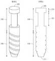
본 발명의 일실시예에 따른 전극 장치(100)는 도 2에 도시된 바와 같이 두개골의 뇌피질 뇌파를 측정하기 위해 사용자의 두개골에 삽입되는 몸체 영역(210); 및 몸체 영역(210)을 통해 흐르는 뇌피질 뇌파를 외부로 전달하는 머리 영역(220)으로 구성될 수 있다.The
이때, 몸체 영역(210)는 사용자의 두개골에 삽입된 몸체 영역(210)이 사용자의 두개골에서 이탈하는 것을 방지하는 형상으로 구성될 수 있다. 예를 들어, 몸체 영역(210)은 도 2에 도시된 바와 같이 나사선 형상으로 구성될 수 있다. 또한, 몸체 영역(210)에 구성된 나사선 형상은 도 2에 도시된 바와 같이 나사선형 홈일 수도 있고, 도 7에 도시된 바와 같이 나사선형 돌출일 수도 있다. 그리고, 몸체 영역(210)의 길이는 사용자(110)의 두개골의 두께를 초과하는 길이일 수 있다.At this time, the
또한, 몸체 영역(210)에서 사용자(110)의 대뇌피질의 상단에 존재하는 경막과 접촉하는 끝부분(211)은 사용자(110)의 뇌피질 뇌파가 흐를 수 있도록 수평 방향으로 일정 이상 면적을 가질 수 있다. 예를 들어, 끝부분(211)의 넓이는 종래의 국소부위 뇌피질 뇌파 전극의 크기에 대응할 수 있다. 또한, 사용자(110)의 뇌피질 뇌파는 사용자(110)의 대뇌피질에 흐르는 전기적 신호일 수 있다.The
그리고, 머리 영역(220)은 머리 영역(220)이 사용자의 신체 및 이물질과 접촉하지 않도록 보호하는 보호 장치가 연결될 수 있다. 이때, 머리 영역(220)은 몸체 영역(210)보다 지름이 작은 영역(221)을 포함하고, 지름이 작은 영역(221)의 위에 영역(221)보다 지름이 큰 영역(222)을 포함할 수 있다.The
보호 장치는 머리 영역(220)과 연결되기 위하여 전극 장치(100) 쪽으로 돌출되는 구성을 포함할 수 있다. 이때, 보호 장치에서 돌출되는 구성은 영역(221)에 삽입될 수 있다. 그리고, 영역(221)에 삽입된 구성은 영역(222)에 의하여 전극 장치(100)의 상부 방향으로의 이동이 제한될 수 있다. 따라서, 보호 장치는 영역(221)에 삽입될 수 있는 구성을 이용하여 머리 영역(220)과 연결될 수 있다.The protection device may include a configuration that protrudes toward the
예를 들어, 전극 장치(100)는 티타늄과 같은 전도성 물질로 형성될 수 있다.For example, the
전기, 및 전기적 신호는 저항이 낮고 전도도가 높은 도체로 흐르며, 도체 중에서도 곡률반경이 큰 곳 보다 작은 표면에 전하가 더 많이 집중되어 표면 전위를 평형상태로 맞출 수 있다. 대뇌피질에 인접한 두개골 또는 다른 물질들은 저항이 높고 전도도가 낮으며 전류의 누수가 거의 없으므로, 대뇌피질에서 흐르는 전기적 신호는 전극 장치(100)로 흐를 수 있다.Electrical and electrical signals flow to conductors with low resistivity and high conductivity, and more charge is concentrated on the surface than the conductor with a large radius of curvature, so that the surface potential can be equilibrated. Electrical signals from the cerebral cortex can flow to the
도 3은 본 발명의 일실시예에 따른 전극 장치가 사용자의 두개골에 삽입된 상태를 나타내는 도면이다.FIG. 3 is a view illustrating a state where an electrode device according to an embodiment of the present invention is inserted into a skull of a user.
사용자의 머리에서 뇌가 위치한 곳의 단면도는 도 3에 도시된 바와 같이 머리의 두피(scalp)(310), 두개골(skull)(320), 경막(dura mater)(330) 및 대뇌피질(cortex)(340)를 포함할 수 있다.The cross-sectional view of the brain where the user's head is located includes
사용자의 머리에 부착하여 사용자의 뇌파를 측정하는 종래의 뇌파 측정 장치는 두피(310)에 전극을 접촉하고, 피부(310)에 흐르는 전기적 신호를 기초로 두피뇌파(EEG)를 측정한다. 그러나, 피부(310)에 흐르는 전기적 신호는 대뇌피질(340)에서 흐르는 전기적 신호가 두개골(320)과 피부(310)를 통과하면서 변질된 신호일 수 있다. 따라서, 피부(310)에 흐르는 전기적 신호를 기초로 측정한 두피뇌파(EEG)는 대뇌피질(340)에서 흐르는 전기적 신호를 기초로 측정한 뇌피질 뇌파(ECoG)에 비하여 시간 해상도와 공간 해상도가 낮을 수 있다.A conventional EEG apparatus for measuring a user's brain wave by attaching to the head of a user contacts an electrode on a
따라서, 전극 장치(100)는 도 3에 도시된 바와 같이 두개골(320)에 삽입되어 경막(330)에 접촉하고, 경막(330)을 통하여 대뇌피질에 흐르는 전기적 신호가 전극 장치(100)를 통해 흐르도록 할 수 있다.3, the
그리고, 전극 장치(100)에서 두개골(320) 외부에 돌출된 머리 영역(220)는 도 3에 도시된 바와 같이 전극 장치(100)를 통해 흐르는 뇌피질 뇌파를 뇌파 측정 장치(120)로 전달하는 뇌파 전달 장치(300)과 연결될 수 있다.3, the
구체적으로, 대뇌피질(340)에 흐르는 전기적 신호는 경막(330)을 통하여 전극 장치(100)의 몸체 영역(210)으로 흐를 수 있다. 이때, 대뇌피질(340)에 흐르는 전기적 신호는 사용자의 뇌피질 뇌파일 수 있다.Specifically, electrical signals flowing through the
그리고, 몸체 영역(210)을 통해 흐르는 전기적 신호는 머리 영역(220)을 통하여 뇌파 전달 장치(300)로 흐를 수 있다. 이때, 뇌파 전달 장치(300)는 뇌파 측정 장치(120)와 연결되어 머리 영역(220)에서 흘러온 전기적 신호를 뇌파 측정 장치(120)로 전달할 수 있다.An electrical signal flowing through the
도 4는 본 발명의 일실시예에 따른 전극 장치에 결합되는 보호 장치의 일례이다.4 is an example of a protection device coupled to an electrode device according to an embodiment of the present invention.
본 발명의 일실시예에 따른 전극 장치(100)에 결합되는 보호 장치(400)는 도 4에 도시된 바와 같이 전극 장치(100)가 사용자의 손이나 머리카락과 같은 사용자의 신체 및 이물질과 접촉하지 않도록 상부가 막힌 원통 형태로 형성될 수 있다.4, the
이때, 보호 장치(400)에서 하부에 형성된 홀(410)은 전극 장치(100)가 삽입될 수 있는 크기의 홀 일 수 있다. 그리고, 홀(410)의 깊이는 전극 장치(100)의 머리 영역(220)의 높이에 따라 결정될 수 있다.In this case, the
또한, 보호 장치(400)는 측면에 전극 장치(100)를 고정하기 위한 고정 장치가 삽입되는 홀(420)을 포함할 수 있다. 고정 장치가 나사인 경우, 홀(420)의 내부에는 나사선이 형성될 수 있다. 이때, 고정 장치는 홀(420)을 통하여 머리 영역(220)의 영역(221)에 근접할 수 있다. 그리고, 영역(221)에 근접한 고정 장치는 보호 장치(400)를 벗기려는 힘이 가해질 경우, 영역(222)와 접촉함으로써, 보호 장치(400)가 벗겨지지 않도록 할 수 있다.In addition, the
도 5는 본 발명의 일실시예에 따른 전극 장치에 결합되는 유출 방지 장치의 일례이다.5 is an example of an outflow preventing device coupled to an electrode device according to an embodiment of the present invention.
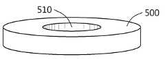
본 발명의 일실시예에 따른 전극 장치(100)는 사용자의 두개골에 형성된 구멍에 삽입될 수 있다. 이때, 전극 장치(100)과 두개골에 형성된 구멍 사이의 틈을 통하여 사용자의 뇌척수액이 유출될 가능성이 있다. 그래서, 전극 장치(100)에 두개골의 구멍에서 뇌척수액이 유출되는 것을 방지하는 유출 방지 장치(500)가 연결될 수 있다.The
이때, 유출 방지 장치(500)는 실리콘이나 고무와 같이 탄성력을 가진 재질로 형성될 수 있다. 그리고, 유출 방지 장치(500)는 전극 장치(100)가 삽입되는 홀(510)을 포함할 수 있다. 이때, 홀(510)의 지름은 전극 장치(100)의 몸체 영역(210)의 지름보다 작을 수 있다. 유출 방지 장치(500)의 재질은 탄성력을 가지므로, 홀(510)의 지름이 몸체 영역(210)의 지름보다 작아도 늘어나면서 전극 장치(100)와 결합될 수 있다. 그리고, 홀(510)의 지름이 몸체 영역(210)의 지름보다 작으므로, 유출 방지 장치(500)는 뇌척수액이 흐를 공간이 없이 재질의 탄성력에 의하여 전극 장치(100)에 밀착 결합될 수 있다.At this time, the
도 6은 본 발명의 일실시예에 따른 전극 장치가 사용자의 두개골에 삽입되는 과정을 나타내는 도면이다.6 is a view illustrating a process of inserting an electrode device according to an embodiment of the present invention into a skull of a user.
단계(610)에서 의사 또는 수술 장치는 사용자의 머리에서 전극 장치(100)가 삽입될 위치를 결정할 수 있다.In
단계(620)에서 의사 또는 수술 장치는 단계(610)에서 결정한 위치에 구멍(621)을 뚫을 수 있다.In
단계(630)에서 의사 또는 수술 장치는 단계(620)에서 뚫은 구멍(621)에 전극 장치(100)을 삽입할 수 있다. 이때, 의사 또는 수술 장치는 전극 장치(100)의 끝이 경막을 찢지 않으면서 경막에 접촉하도록 전극 장치(100)가 삽입되는 깊이를 조절할 수 있다.In
단계(640)에서 의사 또는 수술 장치는 단계(630)에서 삽입한 전극 장치(100)에 유출 방지 장치(500)를 연결하여 구멍(621)에서 뇌척수액이 유출되는 것을 방지할 수 있다.In
단계(640)에서 의사 또는 수술 장치는 단계(630)에서 삽입한 전극 장치(100)에 보호 장치(400)을 연결하여 전극 장치(100)가 사용자의 신체 및 이물질과 접촉하지 않도록 보호할 수 있다. 이때, 의사 또는 수술 장치는 단계(650)에 도시된 바와 같이 보호 장치(400)의 측면에 고정 나사(651)를 결합할 수 있다. 이때, 고정 나사(651)는 전극 장치(100)의 머리 영역과 접촉하거나, 머리 영역에 근접한 상태로 고정될 수 있다. 그리고, 보호 장치(400)를 벗기려는 힘이 가해질 경우, 고정 나사(651)는 머리 영역의 영역(222)와 접촉함으로써, 보호 장치(400)가 벗겨지지 않도록 할 수 있다.In
또한, 사용자의 뇌피질 뇌파를 측정하는 경우, 의사 또는 수술 장치는 단계(630)에서 삽입한 전극 장치(100)에 뇌파 전달 장치(300)과 연결될 수 있다. 이때, 구체적으로, 대뇌피질에 흐르는 전기적 신호는 경막을 통하여 전극 장치(100)로 흐를 수 있다. 그리고, 전극 장치(100)와 연결된 뇌파 전달 장치(300)는 전극 장치(100)을 통해 흐르는 전기적 신호를 뇌파 측정 장치(120)로 전달할 수 있다.In addition, when measuring the brain cortex of the user, the physician or the surgical device may be connected to the
도 7은 본 발명의 일실시예에 따른 전극 장치, 뇌파 전달 장치 및 보호 장치의 일례이다.7 is an example of an electrode device, an EEG transmitting device, and a protecting device according to an embodiment of the present invention.
도 7의 케이스 1(Case 1)은 몸체 영역에 나사선형 돌출이 형성된 전극 장치(100)의 일례이다. 또한, 도 7의 케이스 2(Case 2)는 케이스 1의 전극 장치(100)에 뇌파 전달 장치(300)이 연결된 일례이다.
그리고, 도 7의 케이스 3(Case 3)은 케이스 1의 전극 장치(100)에 보호 장치(400)이 연결된 일례이다.
도 8은 본 발명의 일실시예에 따른 전극 장치가 삽입되는 위치의 일례이다.8 is an example of a position where the electrode device is inserted according to an embodiment of the present invention.
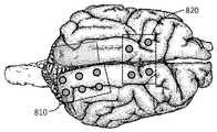
본 발명의 일실시예에 따른 전극 장치(100)는 종래의 패치형 전극에 비하여 절재해야 하는 두개골의 크기 및 두개골의 내부에 삽입되는 전극의 크기가 작으므로, 전극 장치(100)가 삽입되는 위치의 제한이 없다. 예를 들어, 시각적 자극에 대한 뇌파를 측정할 경우, 전극 장치(100)는 도 8에 도시된 바와 같은 뇌의 영역(810)에 대응하는 위치에서 두개골에 삽입될 수 있다. 또한, 사용자의 사지 움직임을 관장하는 뇌파를 측정할 경우, 전극 장치(100)는 도 8에 도시된 바와 같은 뇌의 영역(820)에 대응하는 위치에서 두개골에 삽입될 수 있다.The
즉, 본 발명의 전극 장치(100)는 뇌의 모든 부위에 삽입될 수 있으므로, 뇌 전체의 뇌피질 뇌파를 측정할 수 있다.That is, since the
도 9는 본 발명의 일실시예에 따른 뇌파 측정 장치를 나타내는 도면이다.9 is a diagram illustrating an EEG apparatus according to an embodiment of the present invention.
도 9를 참고하면, 본 발명의 일실시예에 따른 뇌파 측정 장치(120)는 신호 수신부(910) 및 뇌파 측정부(920)를 포함할 수 있다.Referring to FIG. 9, the brain
신호 수신부(910)는 전극 장치(100)로부터 사용자의 대뇌피질에 흐르는 전기적 신호를 수신할 수 있다.The
뇌파 측정부(920)는 신호 수신부(910)가 수신한 전기적 신호에 따라 사용자의 뇌피질 뇌파를 측정할 수 있다. 신호 수신부(910)가 복수의 전극 장치(100)들로부터 전기적 신호를 수신하는 경우, 뇌파 측정부(920)는 신호 수신부(910)가 수신한 복수의 전기적 신호에 기초하여 사용자(110)의 뇌 전체의 뇌피질 뇌파를 측정할 수 있다.The brain
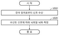
도 10은 본 발명의 일실시예에 따른 뇌파 측정 방법을 도시한 플로우차트이다.FIG. 10 is a flowchart illustrating an EEG measurement method according to an embodiment of the present invention.
단계(1010)에서 신호 수신부(910)는 전극 장치(100)로부터 사용자의 대뇌피질에 흐르는 전기적 신호를 수신할 수 있다.In
단계(1020)에서 뇌파 측정부(920)는 단계(1010)에서 수신한 전기적 신호에 따라 사용자의 뇌피질 뇌파를 측정할 수 있다. 단계(1010)에서 복수의 전극 장치(100)들로부터 전기적 신호를 수신하는 경우, 뇌파 측정부(920)는 단계(1010)에서 수신한 복수의 전기적 신호에 기초하여 사용자(110)의 뇌 전체의 뇌피질 뇌파를 측정할 수 있다.In
본 발명은 나사선 형상으로 구성되는 전극 장치를 사용자의 두개골에 삽입하여 전극의 끝을 대뇌피질 위에 위치한 경막에 접촉시킴으로써, 사용자의 뇌피질 뇌파를 측정할 수 있다. 또한, 본 발명은 종래의 패치형 전극에 비하여 절재해야 하는 두개골의 크기 및 두개골의 내부에 삽입되는 전극의 크기가 작으므로, 뇌의 모든 부위에 삽입하여 뇌 전체의 뇌피질 뇌파를 측정할 수 있다.The present invention can measure the brain cortex of a user by inserting an electrode device having a screw shape into the skull of the user and bringing the tip of the electrode into contact with the epidermis located on the cerebral cortex. In addition, since the size of the skull to be worn and the size of the electrode inserted into the skull are small compared to the conventional patch-type electrode, the present invention can be applied to all parts of the brain to measure the brain cortex of the whole brain.
이상과 같이 본 발명은 비록 한정된 실시예와 도면에 의해 설명되었으나, 본 발명은 상기의 실시예에 한정되는 것은 아니며, 본 발명이 속하는 분야에서 통상의 지식을 가진 자라면 이러한 기재로부터 다양한 수정 및 변형이 가능하다.While the invention has been shown and described with reference to certain preferred embodiments thereof, it will be understood by those of ordinary skill in the art that various changes in form and details may be made therein without departing from the spirit and scope of the invention as defined by the appended claims. This is possible.
그러므로, 본 발명의 범위는 설명된 실시예에 국한되어 정해져서는 아니 되며, 후술하는 특허청구범위뿐 아니라 이 특허청구범위와 균등한 것들에 의해 정해져야 한다.Therefore, the scope of the present invention should not be limited to the described embodiments, but should be determined by the equivalents of the claims, as well as the claims.
100: 전극 장치
120: 뇌파 측정 장치
210: 몸체 영역
220: 머리 영역
300: 뇌파 전달 장치
400: 보호 장치100: electrode device
120: EEG measurement device
210: body region
220: Head area
300: EEG transmitter
400: Protective device
Claims (12)
Translated fromKorean두개골의 뇌피질 뇌파를 측정하기 위해 사용자의 두개골에 삽입되는 몸체 영역; 및 상기 몸체 영역을 통해 흐르는 뇌피질 뇌파를 외부로 전달하는 머리 영역으로 구성되고,
상기 머리 영역은,
상기 몸체 영역보다 지름이 작은 제1 영역 및 상기 제1 영역보다 지름이 크며 상기 제1 영역의 외부 방향에 위치한 제2 영역을 포함하며, 상기 머리 영역이 사용자의 신체 및 이물질과 접촉하지 않도록 보호하는 보호 장치가 연결되고,
상기 보호 장치는,
측면에 상기 전극 장치를 고정하기 위한 고정 장치가 삽입되는 홀을 포함하며,
상기 고정 장치는,
상기 홀을 통하여 상기 제1 영역에 삽입되고, 상기 보호 장치를 벗기려는 힘이 가해질 경우, 상기 보호 장치와 함께 상기 머리 영역의 외부 방향으로 이동하여 상기 제2 영역과 접촉함으로써, 상기 보호 장치가 벗겨지지 않도록 하고,
사용자의 뇌피질 뇌파를 측정하는 경우, 상기 보호 장치가 상기 머리 영역에서 분리되고, 상기 보호 장치를 대신하여 상기 몸체 영역을 통해 흐르는 뇌피질 뇌파를 뇌파 측정 장치로 전달하는 뇌파 전달 장치가 상기 머리 영역에 연결되는 전극 장치.In the electrode device,
A body region inserted into the skull of the user to measure brain cortical brain waves of the skull; And a head region for transmitting a brain cortical brain wave flowing through the body region to the outside,
The head region may include:
A first region having a diameter smaller than that of the body region and a second region having a larger diameter than the first region and positioned in an outward direction of the first region and protecting the head region from contact with the user's body and foreign matter A protective device is connected,
Wherein the protection device comprises:
And a hole into which a fixing device for fixing the electrode device is inserted,
The fixing device includes:
Is inserted into the first region through the hole and moves outwardly of the head region together with the protective device to contact the second region when a force to remove the protective device is applied, However,
When the user's brain cortex is measured, the brain wave transmitting device for separating the protecting device from the head area and delivering the brain cortical EEG flowing through the body area instead of the protecting device to the EEG device, To the electrode unit.
상기 몸체 영역은, 나사선 형상으로 구성되는 전극 장치.The method according to claim 1,
Wherein the body region is formed in a threaded shape.
상기 몸체 영역은,
상기 몸체 영역의 끝부분이 사용자의 대뇌피질의 상단에 존재하는 경막과 접촉하도록 상기 두개골에 삽입되는 전극 장치.The method according to claim 1,
The body region
Wherein an end of the body region is inserted into the skull so as to be in contact with a dural membrane existing at an upper end of the cerebral cortex of the user.
상기 몸체 영역은,
상기 전극 장치가 삽입되는 두개골의 구멍에서 뇌척수액이 유출되는 것을 방지하는 유출 방지 장치가 연결되는 전극 장치.The method according to claim 1,
The body region
Wherein an outflow preventing device for preventing leakage of cerebrospinal fluid from the hole of the skull into which the electrode device is inserted is connected.
상기 전기적 신호에 따라 사용자의 뇌피질 뇌파를 측정하는 뇌파 측정부
를 포함하고,
상기 전극 장치는
두개골의 뇌피질 뇌파를 측정하기 위해 사용자의 두개골에 삽입되는 몸체 영역; 및 상기 몸체 영역을 통해 흐르는 뇌피질 뇌파를 외부로 전달하는 머리 영역으로 구성되고,
상기 머리 영역은,
상기 몸체 영역보다 지름이 작은 제1 영역 및 상기 제1 영역보다 지름이 크며 상기 제1 영역의 외부 방향에 위치한 제2 영역을 포함하며, 상기 머리 영역이 사용자의 신체 및 이물질과 접촉하지 않도록 보호하는 보호 장치가 연결되고,
상기 보호 장치는,
측면에 상기 전극 장치를 고정하기 위한 고정 장치가 삽입되는 홀을 포함하며,
상기 고정 장치는,
상기 홀을 통하여 상기 제1 영역에 삽입되고, 상기 보호 장치를 벗기려는 힘이 가해질 경우, 상기 보호 장치와 함께 상기 머리 영역의 외부 방향으로 이동하여 상기 제2 영역과 접촉함으로써, 상기 보호 장치가 벗겨지지 않도록 하고,
사용자의 뇌피질 뇌파를 측정하는 경우, 상기 보호 장치가 상기 머리 영역에서 분리되고, 상기 보호 장치를 대신하여 상기 몸체 영역을 통해 흐르는 뇌피질 뇌파를 뇌파 측정 장치로 전달하는 뇌파 전달 장치가 상기 머리 영역에 연결되는 뇌파 측정 장치.A signal receiving unit inserted in a user's skull and receiving an electrical signal flowing from an electrode device in contact with a dural sac existing at the top of the user's cerebral cortex to the cerebral cortex of the user; And
An electroencephalogram measuring unit for measuring a brain cortex of the user according to the electrical signal,
Lt; / RTI >
The electrode device
A body region inserted into the skull of the user to measure brain cortical brain waves of the skull; And a head region for transmitting a brain cortical brain wave flowing through the body region to the outside,
The head region may include:
A first region having a diameter smaller than that of the body region and a second region having a larger diameter than the first region and positioned in an outward direction of the first region and protecting the head region from contact with the user's body and foreign matter A protective device is connected,
Wherein the protection device comprises:
And a hole into which a fixing device for fixing the electrode device is inserted,
The fixing device includes:
Is inserted into the first region through the hole and moves outwardly of the head region together with the protective device to contact the second region when a force to remove the protective device is applied, However,
When the user's brain cortex is measured, the brain wave transmitting device for separating the protecting device from the head area and delivering the brain cortical EEG flowing through the body area instead of the protecting device to the EEG device, And an electroencephalogram measuring device connected to the brain.
상기 몸체 영역은, 나사선 형상으로 구성되는 뇌파 측정 장치.
8. The method of claim 7,
Wherein the body region is formed in a thread-like shape.
Priority Applications (1)
| Application Number | Priority Date | Filing Date | Title |
|---|---|---|---|
| KR1020150018100AKR101645852B1 (en) | 2015-02-05 | 2015-02-05 | Screw shaped electrode and apparatus and method for sensing brain signal using screw shaped electrode |
Applications Claiming Priority (1)
| Application Number | Priority Date | Filing Date | Title |
|---|---|---|---|
| KR1020150018100AKR101645852B1 (en) | 2015-02-05 | 2015-02-05 | Screw shaped electrode and apparatus and method for sensing brain signal using screw shaped electrode |
Publications (1)
| Publication Number | Publication Date |
|---|---|
| KR101645852B1true KR101645852B1 (en) | 2016-08-04 |
Family
ID=56709604
Family Applications (1)
| Application Number | Title | Priority Date | Filing Date |
|---|---|---|---|
| KR1020150018100AExpired - Fee RelatedKR101645852B1 (en) | 2015-02-05 | 2015-02-05 | Screw shaped electrode and apparatus and method for sensing brain signal using screw shaped electrode |
Country Status (1)
| Country | Link |
|---|---|
| KR (1) | KR101645852B1 (en) |
Cited By (5)
| Publication number | Priority date | Publication date | Assignee | Title |
|---|---|---|---|---|
| KR101970692B1 (en) | 2017-10-23 | 2019-04-19 | 고려대학교 산학협력단 | Neural signal scanning and recording apparatus for multi-channel implantable neural recording systems and method of the same |
| WO2019164223A1 (en)* | 2018-02-26 | 2019-08-29 | 사회복지법인 삼성생명공익재단 | Screw-type electrode couplable with plug-type wire |
| WO2022256385A1 (en)* | 2021-06-01 | 2022-12-08 | EPIC Neuro, Inc. | Subcutaneous transcranial cortical electrotherapy stimulation method and device |
| US11738203B2 (en) | 2014-10-01 | 2023-08-29 | EPIC Neuro, Inc. | System and method for transcranial current loop brain stimulation |
| US12138458B2 (en) | 2020-07-13 | 2024-11-12 | EPIC Neuro, Inc. | Brain stimulation using subcranial electrode and subcutaneous electrode |
Citations (4)
| Publication number | Priority date | Publication date | Assignee | Title |
|---|---|---|---|---|
| KR20030000927A (en)* | 2001-06-27 | 2003-01-06 | (주)티앤티테크 | Electrode for Electroencephalograph |
| KR20070106007A (en)* | 2005-02-24 | 2007-10-31 | 로우메딕 아게 | Device for measuring brain parameters |
| KR20100031715A (en)* | 2007-07-04 | 2010-03-24 | 고쿠리츠다이가쿠호진 히로시마다이가쿠 | Transcranial electrical stimulation device |
| WO2010038393A1 (en)* | 2008-09-30 | 2010-04-08 | 国立大学法人奈良先端科学技術大学院大学 | Intracerebral information measuring device |
- 2015
- 2015-02-05KRKR1020150018100Apatent/KR101645852B1/ennot_activeExpired - Fee Related
Patent Citations (4)
| Publication number | Priority date | Publication date | Assignee | Title |
|---|---|---|---|---|
| KR20030000927A (en)* | 2001-06-27 | 2003-01-06 | (주)티앤티테크 | Electrode for Electroencephalograph |
| KR20070106007A (en)* | 2005-02-24 | 2007-10-31 | 로우메딕 아게 | Device for measuring brain parameters |
| KR20100031715A (en)* | 2007-07-04 | 2010-03-24 | 고쿠리츠다이가쿠호진 히로시마다이가쿠 | Transcranial electrical stimulation device |
| WO2010038393A1 (en)* | 2008-09-30 | 2010-04-08 | 国立大学法人奈良先端科学技術大学院大学 | Intracerebral information measuring device |
Cited By (7)
| Publication number | Priority date | Publication date | Assignee | Title |
|---|---|---|---|---|
| US11738203B2 (en) | 2014-10-01 | 2023-08-29 | EPIC Neuro, Inc. | System and method for transcranial current loop brain stimulation |
| KR101970692B1 (en) | 2017-10-23 | 2019-04-19 | 고려대학교 산학협력단 | Neural signal scanning and recording apparatus for multi-channel implantable neural recording systems and method of the same |
| WO2019164223A1 (en)* | 2018-02-26 | 2019-08-29 | 사회복지법인 삼성생명공익재단 | Screw-type electrode couplable with plug-type wire |
| KR20190102428A (en)* | 2018-02-26 | 2019-09-04 | 사회복지법인 삼성생명공익재단 | The screw type electrode which is connected to a plug type wire |
| KR102035265B1 (en)* | 2018-02-26 | 2019-10-22 | 사회복지법인 삼성생명공익재단 | The screw type electrode which is connected to a plug type wire |
| US12138458B2 (en) | 2020-07-13 | 2024-11-12 | EPIC Neuro, Inc. | Brain stimulation using subcranial electrode and subcutaneous electrode |
| WO2022256385A1 (en)* | 2021-06-01 | 2022-12-08 | EPIC Neuro, Inc. | Subcutaneous transcranial cortical electrotherapy stimulation method and device |
Similar Documents
| Publication | Publication Date | Title |
|---|---|---|
| KR101645852B1 (en) | Screw shaped electrode and apparatus and method for sensing brain signal using screw shaped electrode | |
| US11583215B2 (en) | Generic ear device with electrodes | |
| CA2868845C (en) | Intracranial sensing & monitoring device with macro and micro electrodes | |
| US6324414B1 (en) | Tunneling lead terminal having a disposal sheath | |
| US10835179B2 (en) | Headset for bio-signals acquisition | |
| CN104382594A (en) | EEG (Electroencephalograph) electrode cap | |
| JPS61249436A (en) | brainwave capture | |
| US20180333066A1 (en) | Apparatus for measuring electroencephalogram, system and method for diagnosing and preventing dementia | |
| KR101704704B1 (en) | Wireless telecommunication module for embedded EEG electrodes and EEG detection system including the same | |
| KR101542115B1 (en) | Head Cap for measuring electro-encephalogram | |
| KR20190056287A (en) | Visual stimulation-based brain-computer interface apparatus and method of processing information thereof | |
| JP2008018017A (en) | Electrode for brain wave measurement | |
| KR20150061609A (en) | Brain signal detecting and brain stimulating system | |
| EP2229977B1 (en) | Electrode for continuously stimulating facial nerve root and apparatus for monitoring electromyograms of facial muscles using the electrode thereof | |
| KR101935666B1 (en) | Detachable needle electrode and multi-channel wireless intraoperative neuromonitoring system having the same | |
| JP6743040B2 (en) | Headset for acquiring biological signals | |
| Terracciano et al. | Pattern-reversal visual evoked potential on smart glasses | |
| KR20200097111A (en) | Headset type Wireless Brain Wave Measuring Apparatus | |
| KR101778268B1 (en) | Medical-treatment electrode assembly | |
| CN203914915U (en) | A kind of intracranial skin electrode | |
| KR101676577B1 (en) | Measurement system and method for measureing of electrocorticogram and cerebral blood flow information | |
| KR20190021933A (en) | Electroencephalogram measurement system using VR device and band | |
| US20130225964A1 (en) | Electrode for intraoperative nerve stimulation | |
| RU2693217C1 (en) | Device for portable wireless recording of cerebral electrical activity | |
| KR200496244Y1 (en) | Neuromuscular relaxation monitoring apparatus |
Legal Events
| Date | Code | Title | Description |
|---|---|---|---|
| PA0109 | Patent application | St.27 status event code:A-0-1-A10-A12-nap-PA0109 | |
| PA0201 | Request for examination | St.27 status event code:A-1-2-D10-D11-exm-PA0201 | |
| P11-X000 | Amendment of application requested | St.27 status event code:A-2-2-P10-P11-nap-X000 | |
| P13-X000 | Application amended | St.27 status event code:A-2-2-P10-P13-nap-X000 | |
| PN2301 | Change of applicant | St.27 status event code:A-3-3-R10-R11-asn-PN2301 St.27 status event code:A-3-3-R10-R13-asn-PN2301 | |
| PN2301 | Change of applicant | St.27 status event code:A-3-3-R10-R11-asn-PN2301 St.27 status event code:A-3-3-R10-R13-asn-PN2301 | |
| D13-X000 | Search requested | St.27 status event code:A-1-2-D10-D13-srh-X000 | |
| D14-X000 | Search report completed | St.27 status event code:A-1-2-D10-D14-srh-X000 | |
| PE0902 | Notice of grounds for rejection | St.27 status event code:A-1-2-D10-D21-exm-PE0902 | |
| E13-X000 | Pre-grant limitation requested | St.27 status event code:A-2-3-E10-E13-lim-X000 | |
| P11-X000 | Amendment of application requested | St.27 status event code:A-2-2-P10-P11-nap-X000 | |
| P13-X000 | Application amended | St.27 status event code:A-2-2-P10-P13-nap-X000 | |
| E701 | Decision to grant or registration of patent right | ||
| PE0701 | Decision of registration | St.27 status event code:A-1-2-D10-D22-exm-PE0701 | |
| PR0701 | Registration of establishment | St.27 status event code:A-2-4-F10-F11-exm-PR0701 | |
| PR1002 | Payment of registration fee | Fee payment year number:1 St.27 status event code:A-2-2-U10-U11-oth-PR1002 | |
| PG1601 | Publication of registration | St.27 status event code:A-4-4-Q10-Q13-nap-PG1601 | |
| P22-X000 | Classification modified | St.27 status event code:A-4-4-P10-P22-nap-X000 | |
| R18-X000 | Changes to party contact information recorded | St.27 status event code:A-5-5-R10-R18-oth-X000 | |
| R18-X000 | Changes to party contact information recorded | St.27 status event code:A-5-5-R10-R18-oth-X000 | |
| FPAY | Annual fee payment | Payment date:20190624 Year of fee payment:4 | |
| PR1001 | Payment of annual fee | Fee payment year number:4 St.27 status event code:A-4-4-U10-U11-oth-PR1001 | |
| PN2301 | Change of applicant | St.27 status event code:A-5-5-R10-R11-asn-PN2301 St.27 status event code:A-5-5-R10-R13-asn-PN2301 | |
| R18-X000 | Changes to party contact information recorded | St.27 status event code:A-5-5-R10-R18-oth-X000 | |
| R18-X000 | Changes to party contact information recorded | St.27 status event code:A-5-5-R10-R18-oth-X000 | |
| PR1001 | Payment of annual fee | Fee payment year number:5 St.27 status event code:A-4-4-U10-U11-oth-PR1001 | |
| PN2301 | Change of applicant | St.27 status event code:A-5-5-R10-R11-asn-PN2301 St.27 status event code:A-5-5-R10-R13-asn-PN2301 | |
| P22-X000 | Classification modified | St.27 status event code:A-4-4-P10-P22-nap-X000 | |
| P22-X000 | Classification modified | St.27 status event code:A-4-4-P10-P22-nap-X000 | |
| R18-X000 | Changes to party contact information recorded | St.27 status event code:A-5-5-R10-R18-oth-X000 | |
| PR1001 | Payment of annual fee | Fee payment year number:6 St.27 status event code:A-4-4-U10-U11-oth-PR1001 | |
| R18-X000 | Changes to party contact information recorded | St.27 status event code:A-5-5-R10-R18-oth-X000 | |
| PR1001 | Payment of annual fee | Fee payment year number:7 St.27 status event code:A-4-4-U10-U11-oth-PR1001 | |
| R18-X000 | Changes to party contact information recorded | St.27 status event code:A-5-5-R10-R18-oth-X000 | |
| R18-X000 | Changes to party contact information recorded | St.27 status event code:A-5-5-R10-R18-oth-X000 | |
| PC1903 | Unpaid annual fee | Not in force date:20230729 Payment event data comment text:Termination Category : DEFAULT_OF_REGISTRATION_FEE St.27 status event code:A-4-4-U10-U13-oth-PC1903 | |
| PC1903 | Unpaid annual fee | Ip right cessation event data comment text:Termination Category : DEFAULT_OF_REGISTRATION_FEE Not in force date:20230729 St.27 status event code:N-4-6-H10-H13-oth-PC1903 | |
| R18-X000 | Changes to party contact information recorded | St.27 status event code:A-5-5-R10-R18-oth-X000 | |
| R18-X000 | Changes to party contact information recorded | St.27 status event code:A-5-5-R10-R18-oth-X000 |