KR101641704B1 - Sensing unit of pipe inspection robot and sensing module of pipe inspection robot comprised of the sensing unit - Google Patents
Sensing unit of pipe inspection robot and sensing module of pipe inspection robot comprised of the sensing unitDownload PDFInfo
- Publication number
- KR101641704B1 KR101641704B1KR1020150170827AKR20150170827AKR101641704B1KR 101641704 B1KR101641704 B1KR 101641704B1KR 1020150170827 AKR1020150170827 AKR 1020150170827AKR 20150170827 AKR20150170827 AKR 20150170827AKR 101641704 B1KR101641704 B1KR 101641704B1
- Authority
- KR
- South Korea
- Prior art keywords
- moving direction
- roller
- cradle
- sensing unit
- coupled
- Prior art date
- Legal status (The legal status is an assumption and is not a legal conclusion. Google has not performed a legal analysis and makes no representation as to the accuracy of the status listed.)
- Active
Links
Images


Classifications
- G—PHYSICS
- G01—MEASURING; TESTING
- G01N—INVESTIGATING OR ANALYSING MATERIALS BY DETERMINING THEIR CHEMICAL OR PHYSICAL PROPERTIES
- G01N27/00—Investigating or analysing materials by the use of electric, electrochemical, or magnetic means
- G01N27/72—Investigating or analysing materials by the use of electric, electrochemical, or magnetic means by investigating magnetic variables
- G01N27/82—Investigating or analysing materials by the use of electric, electrochemical, or magnetic means by investigating magnetic variables for investigating the presence of flaws
- G01N27/90—Investigating or analysing materials by the use of electric, electrochemical, or magnetic means by investigating magnetic variables for investigating the presence of flaws using eddy currents
- B—PERFORMING OPERATIONS; TRANSPORTING
- B25—HAND TOOLS; PORTABLE POWER-DRIVEN TOOLS; MANIPULATORS
- B25J—MANIPULATORS; CHAMBERS PROVIDED WITH MANIPULATION DEVICES
- B25J11/00—Manipulators not otherwise provided for
- B25J11/008—Manipulators for service tasks
- B—PERFORMING OPERATIONS; TRANSPORTING
- B25—HAND TOOLS; PORTABLE POWER-DRIVEN TOOLS; MANIPULATORS
- B25J—MANIPULATORS; CHAMBERS PROVIDED WITH MANIPULATION DEVICES
- B25J19/00—Accessories fitted to manipulators, e.g. for monitoring, for viewing; Safety devices combined with or specially adapted for use in connection with manipulators
- B25J19/02—Sensing devices
- B—PERFORMING OPERATIONS; TRANSPORTING
- B25—HAND TOOLS; PORTABLE POWER-DRIVEN TOOLS; MANIPULATORS
- B25J—MANIPULATORS; CHAMBERS PROVIDED WITH MANIPULATION DEVICES
- B25J5/00—Manipulators mounted on wheels or on carriages
- F—MECHANICAL ENGINEERING; LIGHTING; HEATING; WEAPONS; BLASTING
- F16—ENGINEERING ELEMENTS AND UNITS; GENERAL MEASURES FOR PRODUCING AND MAINTAINING EFFECTIVE FUNCTIONING OF MACHINES OR INSTALLATIONS; THERMAL INSULATION IN GENERAL
- F16L—PIPES; JOINTS OR FITTINGS FOR PIPES; SUPPORTS FOR PIPES, CABLES OR PROTECTIVE TUBING; MEANS FOR THERMAL INSULATION IN GENERAL
- F16L55/00—Devices or appurtenances for use in, or in connection with, pipes or pipe systems
- F16L55/26—Pigs or moles, i.e. devices movable in a pipe or conduit with or without self-contained propulsion means
- G—PHYSICS
- G01—MEASURING; TESTING
- G01B—MEASURING LENGTH, THICKNESS OR SIMILAR LINEAR DIMENSIONS; MEASURING ANGLES; MEASURING AREAS; MEASURING IRREGULARITIES OF SURFACES OR CONTOURS
- G01B7/00—Measuring arrangements characterised by the use of electric or magnetic techniques
- G01B7/02—Measuring arrangements characterised by the use of electric or magnetic techniques for measuring length, width or thickness
- G01B7/06—Measuring arrangements characterised by the use of electric or magnetic techniques for measuring length, width or thickness for measuring thickness
- G01B7/10—Measuring arrangements characterised by the use of electric or magnetic techniques for measuring length, width or thickness for measuring thickness using magnetic means, e.g. by measuring change of reluctance
- G—PHYSICS
- G01—MEASURING; TESTING
- G01N—INVESTIGATING OR ANALYSING MATERIALS BY DETERMINING THEIR CHEMICAL OR PHYSICAL PROPERTIES
- G01N27/00—Investigating or analysing materials by the use of electric, electrochemical, or magnetic means
- G01N27/72—Investigating or analysing materials by the use of electric, electrochemical, or magnetic means by investigating magnetic variables
- G01N27/82—Investigating or analysing materials by the use of electric, electrochemical, or magnetic means by investigating magnetic variables for investigating the presence of flaws
- G01N27/90—Investigating or analysing materials by the use of electric, electrochemical, or magnetic means by investigating magnetic variables for investigating the presence of flaws using eddy currents
- G01N27/9013—Arrangements for scanning
- G01N27/902—Arrangements for scanning by moving the sensors
- F—MECHANICAL ENGINEERING; LIGHTING; HEATING; WEAPONS; BLASTING
- F16—ENGINEERING ELEMENTS AND UNITS; GENERAL MEASURES FOR PRODUCING AND MAINTAINING EFFECTIVE FUNCTIONING OF MACHINES OR INSTALLATIONS; THERMAL INSULATION IN GENERAL
- F16L—PIPES; JOINTS OR FITTINGS FOR PIPES; SUPPORTS FOR PIPES, CABLES OR PROTECTIVE TUBING; MEANS FOR THERMAL INSULATION IN GENERAL
- F16L2101/00—Uses or applications of pigs or moles
- F16L2101/30—Inspecting, measuring or testing
Landscapes
- Engineering & Computer Science (AREA)
- Chemical & Material Sciences (AREA)
- Mechanical Engineering (AREA)
- Physics & Mathematics (AREA)
- Robotics (AREA)
- General Physics & Mathematics (AREA)
- Chemical Kinetics & Catalysis (AREA)
- Health & Medical Sciences (AREA)
- Life Sciences & Earth Sciences (AREA)
- Analytical Chemistry (AREA)
- Biochemistry (AREA)
- General Health & Medical Sciences (AREA)
- Electrochemistry (AREA)
- Immunology (AREA)
- Pathology (AREA)
- General Engineering & Computer Science (AREA)
- Combustion & Propulsion (AREA)
- Investigating Or Analyzing Materials By The Use Of Magnetic Means (AREA)
- Manipulator (AREA)
Abstract
Translated fromKoreanDescription
Translated fromKorean본 발명은 배관검사로봇의 센싱유닛 및 상기 센싱유닛으로 구성된 배관검사로봇의 센싱모듈에 관한 것이다.The present invention relates to a sensing unit of a piping inspection robot and a sensing module of a piping inspection robot composed of the sensing unit.
배관은 시간이 흐름에 따라 부식되고, 주변환경에 따라 파손될 수 있는 바, 그로 인해 발생하는 사고를 미연에 방지하기 위해서는 배관의 상태를 주기적으로 점검할 필요가 있다. 그러나, 배관은 지중에 매설되어 있거나 그 내부에 항상 유체가 흐르는 바, 배관을 점검함에 있어서는 배관을 분리하지 않고 배관의 상태를 점검할 수 있어야 한다.The piping may corrode over time and may be damaged depending on the surrounding environment. In order to prevent the accident from occurring, it is necessary to periodically check the condition of the piping. However, if the piping is buried in the ground or the fluid always flows inside it, the piping should be checked so that the condition of the piping can be checked without detaching the piping.
이를 위해, 배관 내에 흐르는 유체의 흐름으로 피그를 진행시켜 배관의 상태를 파악하는 인텔리전트 피그가 사용되고 있으며, 유체의 흐르는 압력이 낮아 피그를 진행시킬 수 없는 배관 등에 적용하기 위한 언피거블 자가추진 로봇이 개발되고 있다. 이러한 인텔리전트 피그나 언피거블 자가추진 로봇은 비파괴 검사 기술을 이용하여 배관의 두께나 결함 등을 측정하는데, 사용되는 비파괴 검사 기술로는 자기누설법(Magnetic Flux Leakage), 와전류 탐상법(Eddy Current Inspection Method), 리모트 필드 와류탐상시험(Remote Field Eddy Current Testing) 등이 있다.For this purpose, intelligent pigs are used to ascertain the state of the piping by advancing the piggybee with the flow of fluid flowing through the piping, and an unfigured self-propelled robot for application to piping that can not advance the pig due to low fluid pressure Is being developed. These intelligent pig or unfigured self-propelled robots use non-destructive testing techniques to measure the thickness and defects of piping. The non-destructive testing techniques used include magnetic flux leakage, eddy current inspection Method, and Remote Field Eddy Current Testing.
한편, 비파괴 검사 기술을 사용하여 배관의 두께나 결함 등을 측정하기 위해서는, 배관의 두께 등에 따라 달라지는 신호를 검출하는 센싱유닛이 배관의 내주면에 밀착되어야 한다. 그러나, 실제 배관에는 서로 다른 두께의 배관을 용접하여 사용하는 등으로 인해 배관 내부에 단차가 존재하는 바, 배관검사로봇의 센싱유닛은 상기 단차가 존재하는 배관 부분도 전진 뿐만 아니라 후진으로도 통과할 수 있는 구조를 가질 필요가 있다.On the other hand, in order to measure the thickness, defect, etc. of the piping by using the nondestructive inspection technique, the sensing unit for detecting a signal that varies depending on the thickness of the piping, etc., must be closely attached to the inner peripheral surface of the piping. However, since there is a step inside the piping due to the use of pipes of different thicknesses in the actual piping, etc., the sensing unit of the piping inspection robot can not pass the piping part where the step exists, It is necessary to have structure that can be.
또한, 큰 직경을 가지는 배관의 두께나 결함 등을 측정하기 위해서는, 배관 내벽에 대응하는 센싱유닛의 수가 증가되는 바, 배관검사로봇의 센싱모듈은 센싱유닛으로부터 검출된 신호를 효율적으로 처리할 수 있는 구조를 가질 필요가 있다.The number of sensing units corresponding to the inner wall of the pipe is increased in order to measure the thickness and defects of the pipe having a large diameter. Therefore, the sensing module of the pipe inspection robot can efficiently process the signal detected from the sensing unit It is necessary to have a structure.
본 발명의 일실시예는 거치대의 양단에 형성된 제1, 2 경사부와 롤러부를 통해, 배관검사로봇이 전진할 때뿐만 아니라 후진 시에도 배관 내벽에 존재하는 단차를 부드럽게 넘어갈 수 있는 배관검사로봇의 센싱유닛을 제공하며,In an embodiment of the present invention, the first and second slopes and the roller portion formed at both ends of the cradle are used to detect the position of the piping inspection robot, which can smoothly pass over the steps existing on the inner wall of the piping, Sensing unit,
본 발명의 다른 실시예는 복수 개의 센싱유닛 각각에 A/D 변환기를 포함한 기판을 형성하여, 코일 센서로부터 검출된 아날로그 신호를 디지털 신호로 효율적으로 변환시킬 수 있는 배관검사로봇의 센싱모듈을 제공한다.Another embodiment of the present invention provides a sensing module of a piping inspection robot capable of efficiently converting an analog signal detected from a coil sensor into a digital signal by forming a substrate including an A / D converter in each of a plurality of sensing units .
본 발명의 일실시예에 따른 배관검사로봇의 센싱유닛은, 베이스; 상기 베이스의 상부에 결합된 링크부에 의해 상부방향으로 탄성 지지되며, 상부면이 중앙의 평탄부, 상기 평탄부의 일단으로부터 연장되어 제1 이동방향의 하부로 경사진 제1 경사부 및 상기 평탄부의 타단으로부터 연장되어 상기 제1 이동방향과 반대되는 제2 이동방향의 하부로 경사진 제2 경사부로 구성되는 거치대; 상기 제1 경사부의 상면에 내측으로 형성된 제1 결합홈에 결합되되 상기 제1, 2 이동방향으로 회전 가능하도록 결합되며, 상기 제1 경사부의 상면으로부터 일부가 돌출되는 제1 롤러 및 상기 제2 경사부의 상면에 내측으로 형성된 제2 결합홈에 결합되되 상기 제1, 2 이동방향으로 회전 가능하도록 결합되며, 상기 제2 경사부의 상면으로부터 일부가 돌출되는 제2 롤러를 포함하는 롤러부; 및 상기 거치대의 평탄부 중앙에 형성된 장착홈에 결합되고, 적어도 하나 이상의 코일센서를 포함하는 코일센싱부;를 포함한다.A sensing unit of a piping inspection robot according to an embodiment of the present invention includes a base; A first inclined portion which is elastically supported by a link portion coupled to an upper portion of the base and whose upper surface has a central flat portion, a first inclined portion extending from one end of the flat portion and inclined downward in a first moving direction, And a second inclined portion extending from the other end and inclined downward in a second moving direction opposite to the first moving direction; A first roller coupled to a first coupling groove formed on an upper surface of the first inclined portion to be rotatable in the first and second moving directions and partially protruding from an upper surface of the first inclined portion, And a second roller coupled to the second coupling groove formed on the upper side of the upper portion and rotatably coupled in the first and second moving directions and partially protruding from the upper surface of the second inclined portion; And a coil sensing unit coupled to the mounting recess formed at the center of the flat portion of the cradle and including at least one coil sensor.
본 발명의 일실시예에 따른 배관검사로봇의 센싱유닛에 있어, 상기 제1 경사부는 상기 평탄부의 일단으로부터 연장되어 상기 거치대의 하단부까지 상기 제1 이동방향의 하부로 경사지고, 상기 제2 경사부는 상기 평탄부의 타단으로부터 연장되어 상기 거치대의 하단부까지 상기 제2 이동방향의 하부로 경사질 수 있다.In the sensing unit of the piping inspection robot according to an embodiment of the present invention, the first inclined portion extends from one end of the flat portion and is inclined to a lower side of the cradle in the first movement direction, and the second inclined portion And extend from the other end of the flat portion to the lower end of the cradle so as to be inclined downward in the second moving direction.
본 발명의 일실시예에 따른 배관검사로봇의 센싱유닛에 있어, 상기 제1 경사부는, 상기 평탄부의 일단으로부터 연장되어 상기 제1 이동방향의 하부로 경사지고 상면에 상기 제1 롤러가 결합될 수 있도록 상기 제1 결합홈이 내측으로 형성되는 제1 상부경사면; 및 상기 제1 상부경사면으로부터 연장되어 상기 거치대의 하단부까지 상기 제1 이동방향의 하부로 경사진 제1 하부경사면;을 포함하고, 상기 제2 경사부는, 상기 평탄부의 타단으로부터 연장되어 상기 제2 이동방향의 하부로 경사지고 상면에 상기 제2 롤러가 결합될 수 있도록 상기 제2 결합홈이 내측으로 형성되는 제2 상부경사면; 및 상기 제2 상부경사면으로부터 연장되어 상기 거치대의 하단부까지 상기 제2 이동방향의 하부로 경사진 제2 하부경사면;을 포함하고, 상기 제1 및 제2 상부경사면의 기울기는 상기 제1 및 제2 하부경사면의 기울기보다 더 완만할 수 있다.In the sensing unit of the piping inspection robot according to an embodiment of the present invention, the first inclined portion may extend from one end of the flat portion and be inclined downward in the first moving direction, and the first roller may be coupled to the upper surface A first upper inclined surface in which the first engaging groove is formed inward; And a first lower inclined surface extending from the first upper inclined surface and inclined to a lower portion of the first moving direction from the lower end of the cradle to the lower end of the cradle, the second inclined portion extending from the other end of the flat portion, A second upper inclined surface inclined to a lower side of the first engaging groove and having the second engaging groove formed inward so that the second roller can be engaged with the upper surface; And a second lower inclined surface extending from the second upper inclined surface and inclined to a lower portion of the second moving direction to a lower end of the cradle, wherein a slope of the first and second upper inclined surfaces is smaller than a slope of the first and second upper inclined surfaces, It may be more gentle than the inclination of the lower inclined plane.
본 발명의 일실시예에 따른 배관검사로봇의 센싱유닛에 있어, 상기 링크부는, 상기 베이스 상면의 상기 제1 이동방향의 일단에 회전 가능하게 결합되어 상기 거치대 하면의 상기 제1 이동방향의 일단을 지지하는 제1 지지링크 및 상기 베이스의 중앙부에 회전 가능하게 결합되어 외주면에 형성된 제1 탄성부재를 통해 상기 제1 지지링크를 상부방향으로 탄성 지지하는 제1 탄성링크를 포함하는 제1 링크부재; 및 상기 베이스 상면의 상기 제2 이동방향의 타단에 회전 가능하게 결합되어 상기 거치대 하면의 상기 제2 이동방향의 타단을 지지하는 제2 지지링크 및 상기 베이스의 중앙부에 회전 가능하게 결합되어 외주면에 형성된 제2 탄성부재를 통해 상기 제2 지지링크를 상부방향으로 탄성 지지하는 제2 탄성링크를 포함하는 제2 링크부재를 포함하고, 상기 제1 링크부재와 제2 링크부재는 상기 거치대를 상호 독립적으로 탄성 지지할 수 있다.In the sensing unit of the piping inspection robot according to an embodiment of the present invention, the link portion is rotatably coupled to one end of the upper surface of the base in the first movement direction, and is connected to one end of the lower surface of the cradle in the first movement direction A first link member including a first support link for supporting the first support link and a first elastic link for elastically supporting the first support link in an upward direction through a first elastic member rotatably coupled to the center of the base and formed on an outer circumferential surface; And a second support link rotatably coupled to the upper surface of the base at the other end in the second movement direction and supporting the other end of the lower surface of the cradle in the second movement direction, And a second link member including a second elastic link for elastically supporting the second support link in an upward direction through a second elastic member, wherein the first link member and the second link member are arranged so that the cradle It can be elastically supported.
본 발명의 일실시예에 따른 배관검사로봇의 센싱유닛에 있어, 상기 롤러부의 제1, 2 롤러는 상기 제1, 2 경사부의 상면에 대해 상기 제1, 2 롤러의 반경 이하로 돌출될 수 있다.In the sensing unit of the piping inspection robot according to an embodiment of the present invention, the first and second rollers of the roller portion may protrude below the radius of the first and second rollers with respect to the upper surface of the first and second slopes .
본 발명의 일실시예에 따른 배관검사로봇의 센싱유닛에 있어, 상기 롤러부의 제1, 2롤러는 상기 평탄부의 연장선보다 더 돌출되어 배관의 내벽에 접촉될 수 있다.In the sensing unit of the piping inspection robot according to an embodiment of the present invention, the first and second rollers of the roller portion may protrude further than the extension of the flat portion and may contact the inner wall of the pipe.
본 발명의 다른 실시예에 따른 배관검사로봇의 센싱모듈은, 베이스, 상기 베이스의 상부에 결합된 링크부에 의해 상부방향으로 탄성 지지되며 상부면이 중앙의 평탄부와 상기 평탄부의 일단으로부터 연장되어 제1 이동방향의 하부로 경사진 제1 경사부와 상기 평탄부의 타단으로부터 연장되어 상기 제1 이동방향과 반대되는 제2 이동방향의 하부로 경사진 제2 경사부로 구성되는 거치대, 상기 제1 경사부의 상면에 내측으로 형성된 제1 결합홈에 결합되되 상기 제1, 2 이동방향으로 회전 가능하도록 결합되며, 상기 제1 경사부의 상면으로부터 일부가 돌출되는 제1 롤러와 상기 제2 경사부의 상면에 내측으로 형성된 제2 결합홈에 결합되되 상기 제1, 2 이동방향으로 회전 가능하도록 결합되며, 상기 제2 경사부의 상면으로부터 일부가 돌출되는 제2 롤러를 포함하는 롤러부 및 상기 거치대의 평탄부 중앙에 형성된 장착홈에 결합되고 적어도 하나 이상의 코일센서를 포함하는 코일센싱부를 포함하는 배관검사로봇의 센싱유닛이 상기 베이스를 중심으로 배관 내벽에 대응되도록 방사방향으로 복수개가 형성될 수 있다.The sensing module of the piping inspection robot according to another embodiment of the present invention includes a base and a link portion coupled to an upper portion of the base, the sensor module being elastically supported in an upper direction, the upper surface of the sensing module extending from a center flat portion and one end of the flat portion A cradle including a first inclined portion inclined downward in the first moving direction and a second inclined portion extending from the other end of the flat portion and inclined downward in a second moving direction opposite to the first moving direction, A first roller coupled to a first coupling groove formed on an upper surface of the first inclined portion to be rotatable in the first and second moving directions and partially protruding from the upper surface of the first inclined portion, And a second roller coupled to the second engaging groove formed in the second engaging groove to be rotatable in the first and second moving directions and partially protruding from the upper surface of the second angled portion, And a coil sensing part coupled to a mounting groove formed at the center of the flat part of the cradle and including at least one coil sensor is disposed in the radial direction As shown in FIG.
본 발명의 다른 실시예에 따른 배관검사로봇의 센싱모듈에 있어, 상기 코일센싱부는, 상기 제1, 2 이동방향에 대해 사선으로 형성되고, 배관 내벽에 대응되도록 굴곡질 수 있다.In the sensing module of the piping inspection robot according to another embodiment of the present invention, the coil sensing part may be formed obliquely with respect to the first and second moving directions, and may be bent to correspond to the inner wall of the pipe.
본 발명의 다른 실시예에 따른 배관검사로봇의 센싱모듈에 있어, 상기 코일센싱부는, 적어도 하나 이상의 코일센서; 상기 코일센서의 하단에 형성되어 상기 코일센서와 전기적으로 연결되는 기판; 및 상기 코일센서 및 기판을 수용하는 케이스;를 포함하고, 상기 기판에는 상기 코일센서로부터 감지된 아날로그 신호로 디지털 신호로 직접 변환시키는 A/D 컨버터가 형성될 수 있다.In the sensing module of the piping inspection robot according to another embodiment of the present invention, the coil sensing unit may include at least one coil sensor; A substrate formed on a lower end of the coil sensor and electrically connected to the coil sensor; And a case for receiving the coil sensor and the substrate, wherein the substrate is provided with an A / D converter for directly converting the analog signal detected from the coil sensor into a digital signal.
본 발명의 특징 및 이점들은 첨부도면에 의거한 다음의 상세한 설명으로 더욱 명백해질 것이다.The features and advantages of the present invention will become more apparent from the following detailed description based on the accompanying drawings.
이에 앞서, 본 명세서 및 청구범위에 사용된 용어나 단어는 통상적이고 사전적인 의미로 해석되어서는 아니되며, 발명자가 그 자신의 발명을 가장 최선의 방법으로 설명하기 위해 용어의 개념을 적절하게 정의할 수 있다는 원칙에 입각하여 본 발명의 기술적 사상에 부합되는 의미와 개념으로 해석되어야만 한다.Prior to this, terms and words used in the present specification and claims should not be construed in a conventional and dictionary sense, and the inventor may appropriately define the concept of a term in order to best describe its invention The present invention should be construed in accordance with the spirit and scope of the present invention.
본 발명의 일실시예에 따르면, 센싱유닛은, 거치대의 제1, 2 이동방향 양단에 형성되는 제1, 2 경사부로 인해, 배관 내부에 존재하는 단차를 제1 이동방향뿐만 아니라 제2 이동방향으로도 유연하게 통과할 수 있는 효과가 있다.According to an embodiment of the present invention, the sensing unit includes a first and second inclined portions formed at both ends of the cradle in the first and second moving directions, so that the step existing in the piping can be moved not only in the first moving direction, So that it is possible to pass smoothly.
또한, 제1, 2 경사부는 평탄부의 양단으로부터 거치대의 하단부까지 경사질 수 있는 바, 센싱유닛은 거치대 높이 이내의 배관 내부의 단차를 통과할 수 있는 효과가 있다.In addition, the first and second inclined portions can be inclined from both ends of the flat portion to the lower end portion of the cradle, and the sensing unit can pass the step inside the piping within the height of the cradle.
또한, 제1, 2 상부경사면의 기울기는 제1, 2 하부경사면의 기울기보다 더 완만하여, 배관의 단차를 통과함에 따라 거치대가 점진적으로 기울어져 제1, 2 경사부의 기울기가 상승하더라도, 배관 내의 단차를 유연하게 통과할 수 있는 효과가 있다.The inclination of the first and second upper inclined surfaces is gentler than the inclination of the first and second lower inclined surfaces so that even if the inclination of the first and second inclined surfaces increases gradually as the table is gradually tilted as it passes the step of the pipe, There is an effect that the step can be passed smoothly.
또한, 제1 링크부재와 제2 링크부재가 거치대를 상호 독립적인 탄성 지지함에 따라 거치대가 기울어질 수 있어, 거치대에 가해지는 하부 방향의 힘이 작더라도 배관 내의 단차를 유연하게 통과할 수 있는 효과가 있다.Further, since the cradle can be inclined as the first link member and the second link member elastically support the cradle independently of each other, even if the force in the downward direction applied to the cradle is small, .
또한, 센싱유닛은, 제1, 2 경사부의 제1, 2 결합홈에 결합된 롤러부를 포함하여, 배관 내에서 부드럽게 주행할 수 있는 효과가 있다.Further, the sensing unit includes a roller portion coupled to the first and second engagement grooves of the first and second inclined portions, so that the sensing unit can smoothly travel in the pipe.
또한, 롤러부의 돌출 높이는 제1, 2 롤러의 반경 이하로 형성될 수 있는 바, 제1, 2 롤러의 반경이 크더라도 제1, 2 롤러가 배관의 단차에 걸리지 않아, 센싱유닛이 배관의 단차를 통과할 수 있는 효과가 있다.The protruding height of the roller portion can be less than the radius of the first and second rollers. Even if the radius of the first and second rollers is large, the first and second rollers do not interfere with the step of the pipe, There is an effect that it can pass through.
또한, 제1, 2 롤러의 돌출은 평탄부의 연장선보다 더 돌출되어, 제1, 2 롤러가 배관의 내벽에 접촉될 수 있는 바, 단차없는 배관 부분을 주행할 때에서 롤러부가 배관 내벽에 접촉되어 센싱유닛이 배관을 부드럽게 주행할 수 있는 효과가 있다.Further, the protrusions of the first and second rollers protrude more than the extension of the flat portion, so that the first and second rollers can be brought into contact with the inner wall of the pipe, and when the stepped portion of the pipe runs, the roller contacts the inner wall of the pipe The sensing unit can smoothly run the piping.
본 발명의 다른 실시예에 따르면, 센싱모듈은 복수개의 센싱유닛으로 형성되고, 센싱유닛의 코일센싱부 각각이 제1, 2 이동방향에 대해 사선으로 형성되어, 센싱유닛 사이의 공간에서도 배관의 두께 변화 내지 결함을 측정할 수 있는 효과가 있다.According to another embodiment of the present invention, the sensing module is formed of a plurality of sensing units, and each of the coil sensing parts of the sensing unit is formed obliquely with respect to the first and second moving directions, so that even in the space between the sensing units, There is an effect that the change or defect can be measured.
또한, 코일센싱부마다 코일센서 하단에 A/D 컨버터가 형성된 기판이 형성되어, 복수개의 아날로그 신호를 디지털 신호로 동시에 변환할 수 있으며, 아날로그 신호가 디지털 신호로 변환됨에 있어 배선 길이가 짧아 노이즈 요인의 개입이 최소화될 수 있는 효과가 있다.In addition, since a substrate on which an A / D converter is formed at the coil sensor bottom is formed for each coil sensing unit, a plurality of analog signals can be simultaneously converted into digital signals, and analog signals are converted into digital signals, There is an effect that the intervention of the user can be minimized.
도 1은 본 발명의 일실시예에 따른 배관검사로봇의 전체를 도시한 도면;
도 2는 본 발명의 일실시예에 따른 배관검사로봇의 센싱유닛의 일부 분해 사시도;
도 3은 본 발명의 일실시예에 따른 배관검사로봇의 센싱유닛의 일측면도;
도 4a 및 도 4b는 본 발명의 일실시예에 따른 배관검사로봇의 센싱유닛이 배관 내의 단차를 통과할 때 및 통과한 후의 일측면도;
도 5는 본 발명의 다른 실시예에 따른 배관검사로봇의 센싱모듈의 사시도 및 부분 확대도이다.BRIEF DESCRIPTION OF THE DRAWINGS FIG. 1 is a view showing an entire piping inspection robot according to an embodiment of the present invention; FIG.
2 is a partially exploded perspective view of a sensing unit of a piping inspection robot according to an embodiment of the present invention;
3 is a side view of a sensing unit of a piping inspection robot according to an embodiment of the present invention;
FIGS. 4A and 4B are side views of a sensing unit of a piping inspection robot according to an embodiment of the present invention when the sensing unit passes through and after passing through a step in the piping; FIG.
5 is a perspective view and a partial enlarged view of a sensing module of a piping inspection robot according to another embodiment of the present invention.
본 발명의 목적, 특정한 장점들 및 신규한 특징들은 첨부된 도면들과 연관 되어지는 이하의 상세한 설명과 바람직한 실시예들로부터 더욱 명백해질 것이다.BRIEF DESCRIPTION OF THE DRAWINGS The objectives, specific advantages and novel features of the present invention will become more apparent from the following detailed description taken in conjunction with the accompanying drawings, in which: FIG.
본 명세서에서 각 도면의 구성요소들에 참조번호를 부가함에 있어서, 동일한 구성 요소들에 한해서는 비록 다른 도면상에 표시되더라도 가능한 동일한 번호를 가지도록 하고 있음에 유의하여야 한다.It should be noted that the reference numerals are added to the components of the drawings in the present specification with the same numerals as possible, even if they are displayed on different drawings, for the same components.
또한, “일면”, “타면”, “제1”, “제2” 등의 용어는 하나의 구성요소를 다른 구성요소로부터 구별하기 위해 사용되는 것으로, 구성요소가 상기 용어들에 의해 제한되는 것은 아니다. 특히, 본원에 기재된 “제1 이동방향”은 배관검사로봇(1)이 전진으로 배관 내부를 이동하는 방향, 즉 도 3에 도시된 좌측 화살표 방향을 말하며, “제2 이동방향”은 배관검사로봇(1)이 후진으로 배관 내부를 이동하는 방향, 즉 도 3에 도시된 우측 화살표 방향을 말한다.Also, the terms " one side, " " first, " " first, " " second, " and the like are used to distinguish one element from another, no. Specifically, the "first moving direction" described herein refers to the direction in which the pipe inspection robot 1 moves forward within the pipe, that is, the left arrow direction shown in FIG. 3, and the "second moving direction" Refers to the direction of movement of the inside of the pipe 1 backward, that is, the right arrow direction shown in Fig.
이하, 첨부된 도면을 참조하여, 본 발명인 배관검사로봇(1)의 센싱유닛(10B)에 대한 일실시예를 상세히 설명한다. 한편, 본 발명은 언피거블 자가추진 로봇 시스템뿐만 아니라 인텔리전트 피그 시스템에도 적용될 수 있으며, 여러가지 비파괴 검사 기술에 적용될 수 있으나, 본 발명의 일실시예는 언피거블 자가추진 로봇과 리모트 필드 와류탐상시험을 기준으로 설명하도록 한다.Hereinafter, one embodiment of the
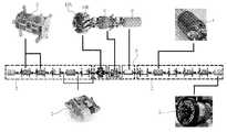
도 1은 본 발명의 일실시예에 따른 배관검사로봇(1)의 전체를 도시한 도면이다.FIG. 1 is a view showing an entire piping inspection robot 1 according to an embodiment of the present invention.
도 1에 도시된 바와 같이, 배관검사로봇(1)은 자가추진 로봇모듈(2), 센싱부(8), 컨트롤러(6)를 포함한다.1, the piping inspection robot 1 includes a self-propelled
자가추진 로봇모듈(2)은, 드라이버모듈(3)을 포함하고 배관검사로봇(1)의 전방 및 후방에 형성되어 배관검사로봇(1) 전체를 배관 내부에서 전방 또는 후방으로 견인한다. 또한, 자가추진 로봇모듈(2)은 배터리모듈(4)을 포함하여 배관검사로봇(1)의 작동에 필요한 전원을 공급하며, 카메라모듈(5)을 포함할 수 있어 배관 내부를 촬영함으로써 배관 내부의 장애물 존부, 배관의 경로, 분기관의 유무 등의 정보를 포함하는 상태변화정보를 생성할 수 있다.The self
그리고, 센싱부(8)는, 익사이터(9)를 포함하여 기설정된 진폭과 주파수를 갖는 기준신호를 출력함으로써 배관 내부의 자기장을 생성하며, 센싱모듈(10A)을 포함하여 원격필드에서 배관의 두께변화에 따른 와전류 전파시간의 변화를 검출한다. 이러한 센싱모듈(10A)은 복수개의 센싱유닛(10B)의 배관 내벽에 대응되도록 방사방향으로 형성되어 구성된다. 한편, 센싱유닛(10B)은, 와전류 전파시간의 변화를 정확히 검출하기 위해, 배관의 직경이 변화하더라도 배관 내벽에 밀착되어야 하는 바, 탄성부재 등에 의해 센싱유닛(10B)은 배관 내벽 방향으로 탄성 지지된다.The
또한, 컨트롤러(6)는 센싱부(8)로부터 검출된 와전류의 전파시간의 변화에 기초하여 배관의 두께변화정보를 생성하며, 배관내부의 상태변화정보에 기초하여 배관검사로봇(1)의 동작상태를 제어할 수 있다.The controller 6 generates thickness change information of the pipe on the basis of a change in the propagation time of the eddy current detected from the
그리고, 각 모듈, 센싱부(8) 및 컨트롤러(6)는 조인트모듈(7)로 연결되어, 배관검사로봇(1)은 각 조인트모듈(7)마다 굴절될 수 있다.Each module, the
한편, 배관검사로봇(1)은 전진뿐만 아니라 후진으로도 배관 내부를 주행하는 바, 배관 내벽에 밀착되는 배관검사로봇(1)의 센싱유닛(10B)은 배관 내부의 단차를 전진 방향인 제1 이동방향뿐만 아니라 후진 방향인 제2 이동방향으로도 넘을 수 있는 구조를 가질 필요가 있다. 따라서, 이하에서는 제1 이동방향뿐만 아니라 제2 이동방향으로도 배관 내부의 단차를 통과할 수 있는, 본 발명의 일실시예에 따른 배관검사로봇(1)의 센싱유닛(10B)에 대해 상세히 설명한다.On the other hand, the piping inspection robot 1 travels not only forward but also backward, and the
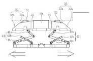
도 2는 본 발명의 일실시예에 따른 배관검사로봇(1)의 센싱유닛(10B)의 일부 분해 사시도, 도 3은 본 발명의 일실시예에 따른 배관검사로봇(1)의 센싱유닛(10B)의 일측면도, 도 4a 및 도 4b는 본 발명의 일실시예에 따른 배관검사로봇(1)의 센싱유닛(10B)이 배관 내의 단차를 통과할 때 및 통과한 후의 일측면도이다.FIG. 2 is a partially exploded perspective view of a
본 발명의 일실시예에 따른 배관검사로봇(1)의 센싱유닛(10B)은, 도2 내지 도4에 도시된 바와 같이, 베이스(20), 상기 베이스(20)의 상부에 결합된 링크부(40)에 의해 상부방향으로 탄성 지지되며, 상부면이 중앙의 평탄부(31), 상기 평탄부(31)의 일단으로부터 연장되어 제1 이동방향의 하부로 경사진 제1 경사부(32) 및 상기 평탄부(31)의 타단으로부터 연장되어 상기 제1 이동방향과 반대되는 제2 이동방향의 하부로 경사진 제2 경사부(33)로 구성되는 거치대(30), 상기 제1 경사부(32)의 상면에 내측으로 형성된 제1 결합홈(32c)에 결합되되 상기 제1, 2 이동방향으로 회전 가능하도록 결합되며, 상기 제1 경사부(32)의 상면으로부터 일부가 돌출되는 제1 롤러(51) 및 상기 제2 경사부(33)의 상면에 내측으로 형성된 제2 결합홈(33c)에 결합되되 상기 제1, 2 이동방향으로 회전 가능하도록 결합되며, 상기 제2 경사부(33)의 상면으로부터 일부가 돌출되는 제2 롤러(52)를 포함하는 롤러부(50) 및 상기 거치대(30)의 평탄부(31) 중앙에 형성된 장착홈(31a)에 결합되고, 적어도 하나 이상의 코일센서(61)를 포함하는 코일센싱부(60)를 포함하여, 배관 내부에 존재하는 단차를 제1 이동방향뿐만 아니라 제2 이동방향으로도 유연하게 통과할 수 있다.2 to 4, the
베이스(20)는 배관검사로봇(1)에 있어서 센싱유닛(10B)을 인접하는 모듈과 연결시키기 위해 조인트 모듈이 결합되는 부분으로, 배관검사로봇(1)의 전방 및 후방에 장착된 자가추진 로봇모듈(2)에 견인되어(도1 참조), 제1 이동방향 또는 제2 이동방향으로 견인된다. 또한, 베이스(20)는 후술할 링크부(40) 및 거치대(30)를 지지하는 구성으로, 도 2에 도시된 바와 같이, 제1 이동방향 및 제2 이동방향을 따라 길게 형성된 판상형의 부재로 구성될 수 있다. 다만, 베이스(20)의 구체적인 형태는 판상형에 한하지 않고, 다양하게 형성될 수 있다.The
거치대(30)는 후술할 코일 센싱부(8)가 배관 내벽에 밀착되도록 코일 센싱부(8)를 지지하는 구성으로, 베이스(20) 상부에 결합된 링크부(40)에 의해 상부 방향으로 탄성 지지된다. 이에 따라, 거치대(30)에 하부 방향의 힘이 작용하는 경우, 링크부(40)의 탄성에 의해 거치대(30)는 어느 정도 하부 방향으로 이동될 수 있다.The
또한, 배관 내부의 단차를 통과함에 있어서, 거치대(30)에 하부 방향의 힘이 가해질 수 있도록, 거치대(30)의 상부면은 중앙의 평탄부(31) 및 평탄부(31) 양단으로부터 연장된 제1, 2 경사부(32, 33)로 구성될 수 있다. 이 때, 제1 경사부(32)는, 도 2 내지 4에 도시된 바와 같이, 제1 이동방향의 하부로 경사지어 배관검사로봇(1)이 제1 이동방향으로 주행함에 있어서 존재하는 단차를 통과할 수 있게 하고, 제2 경사부(33)는 제2 이동방향의 하부로 경사지어 배관검사로봇(1)이 제2 이동방향으로 주행함에 있어서 존재하는 단차를 통과할 수 있게 한다. 즉, 제1, 2 경사부(32, 33)에 의해 배관검사로봇(1)의 센싱유닛(10B)은 제1 이동방향뿐만 아니라 제2 이동방향으로도 배관 내부에 존재하는 단차를 통과할 수 있다.The upper surface of the
이와 같은, 제1, 2 경사부(32, 33)는 거치대(30) 상부의 일정영역에 한하여 형성될 수 있으나, 도 2 내지 4에 도시된 바와 같이 평탄부(31)에서부터 거치대(30)의 하단부까지 형성될 수 있다. 즉, 제1 경사부(32)는 평탄부(31)의 일단으로부터 연장되어 거치대(30)의 하단부까지 제1 이동방향 하부로 경사질 수 있고, 제2 경사부(33)는 평탄부(31)의 타단으로부터 연장되어 거치대(30)의 하단부까지 제2 이동방향 하부로 경사질 수 있다. 이에 따라, 배관검사로봇(1)의 센싱유닛(10B)은 거치대(30) 높이 이내의 배관 내부의 단차를 통과할 수 있다. 제1, 2 경사부(32, 33)의 수직적 길이는 이에 한하지 않고, 거치대(30)의 하단부보다 더 하부로 연장될 수도 있다.The first and second
한편, 제1, 2 경사부(32, 33)는 전반적으로 단일의 기울기를 가진 하나의 경사면으로 구성될 수 있고, 서로 다른 기울기를 가진 복수의 경사면으로 구성될 수 있다. 후자의 경우, 제1 경사부(32)는 평탄부(31)의 일단으로부터 연장되어 제1 이동방향의 하부로 경사지고 상면에 제1 롤러(51)가 결합될 수 있도록 제1 결합홈(32c)이 내측으로 형성된 제1 상부경사면(32a) 및 제1 상부경사면(32a)으로부터 연장되어 거치대(30)의 하단부까지 제1 이동방향의 하부로 경사진 제1 하부경사면(32b)을 포함할 수 있다. 이 경우, 제1 상부경사면(32a)의 기울기는 제1 하부경사면(32b)의 기울기보다 더 완만하게 형성된다. 이에 따라, 배관검사로봇(1)의 센싱유닛(10B)은 제1 하부경사면(32b)이 제한된 길이에서 더 큰 높이를 가지는 바, 배관 내의 더 큰 단차를 통과할 수 있다. 또한, 배관 내의 단차를 통과함에 있어서 배관 내의 단차와 제1 경사부(32)의 상부가 접할수록 거치대(30)가 기울어져 제1 경사부(32)의 기울기가 상승할 수 있는데, 제1 상부경사면(32a)의 기울기를 완만하게 구성하여, 제1 경사부(32) 기울기 상승에 불구하고, 배관 내의 단차를 유연하게 통과할 수 있다. 한편, 제2 경사부(33) 또한, 제1 경사부(32)에 대응하여, 평탄부(31)의 타단으로부터 연장되어 제2 이동방향의 하부로 경사지고 상면에 제2 롤러(52)가 결합될 수 있도록 제2 결합홈(33c)이 내측으로 형성되는 제2 상부경사면(33a) 및 제2 상부경사면(33a)으로부터 연장되어 거치대(30)의 하단부까지 제2 이동방향의 하부로 경사진 제2 하부경사면(33b)을 포함할 수 있고, 이 경우 제2 상부경사면(33a)의 기울기는 제2 하부경사면(33b)의 기울기보다 더 완만할 수 있다. 제1, 2 경사부(32, 33)의 기울기는 이에 한하지 않고, 상부로 갈수록 기울기가 완만해지는 곡선으로 구성될 수 있다.On the other hand, the first and second
거치대(30)를 상부 방향으로 탄성 지지하는 링크부(40)는, 제1 링크부재(41)와 제2 링크부재(42)를 포함할 수 있고, 제1 링크부재(41)와 제2 링크부재(42)는 거치대(30)를 상호 독립적으로 탄성 지지할 수 있다. 제1 링크부재(41)와 제2 링크부재(42)의 상호 독립적인 탄성 지지에 의해, 거치대(30)가 기울어질 수 있어 거치대(30)에 가해지는 하부 방향의 힘이 작더라도 배관 내의 단차를 유연하게 통과할 수 있다. 구체적으로 제1 링크부재(41)는 베이스(20) 상면의 제1 이동방향의 일단에 회전 가능하게 결합되어 거치대(30) 하면의 제1 이동방향의 일단을 지지하는 제1 지지링크(41a) 및 베이스(20)의 중앙부에 회전 가능하게 결합되어 외주면에 형성된 제1 탄성부재(41c)를 통해 제1 지지링크(41a)를 상부방향으로 탄성 지지하는 제1 탄성링크(41b)를 포함할 수 있고, 제2 링크부재(42)는 제1 링크부재(41)에 대응하여, 베이스(20) 상면의 제2 이동방향의 타단에 회전 가능하게 결합되어 거치대(30) 하면의 제2 이동방향의 타단을 지지하는 제2 지지링크(42a) 및 베이스(20)의 중앙부에 회전 가능하게 결합되어 외주면에 형성된 제2 탄성부재(42c)를 통해 제2 지지링크(42a)를 상부방향으로 탄성 지지하는 제2 탄성링크(42b)를 포함할 수 있다. 다만, 링크부(40)의 구체적인 구조는 이에 한정되지 않고, 베이스(20)로부터 거치대(30)를 상부방향으로 탄성 지지할 수 있는 구조라면 본 발명에 포함될 수 있다.The
롤러부(50)는 배관검사로봇(1)의 센싱유닛(10B)이 배관 내에서 부드럽게 주행할 수 있도록 하는 구성으로, 제1 롤러(51)와 제2 롤러(52)를 포함한다. 제1 롤러(51)는 제1 경사부(32)의 상면, 구체적으로는 제1 경사부(32)의 제1 상부경사면(32a)에 내측으로 형성된 제1 결합홈(32c)에 결합되되 제1, 2 이동방향으로 회전 가능하도록 결합되며, 제1 경사부(32)의 상면으로부터 일부가 돌출된다. 그리고, 제2 롤러(52)는 제2 경사부(33)의 상면, 즉 제2 경사부(33)의 제2 상부경사면(33a)에 내측으로 형성된 제2 결합홈(33c)에 결합되되 제1, 2 이동방향으로 회전 가능하도록 결합되며, 제2 경사부(33)의 상면으로부터 일부가 돌출된다. 제1, 2 롤러(51, 52)는 도 2 내지 4에 도시된 바와 같이, 하나로 구성될 수 있으나, 이와 달리 제1, 2 경사부(32, 33)를 따라 복수개로 구성될 수 있다.The
한편, 제1, 2 롤러(51, 52)가 제1, 2 경사부(32, 33)의 상면으로부터 돌출됨에 있어, 그 돌출 높이는 제1, 2 롤러(51, 52)의 반경 이하로 돌출될 수 있다. 이에 따라, 제1, 2 롤러(51, 52)의 반경이 크더라도 제1, 2 롤러(51, 52)가 배관 내의 단차에 걸리지 않아, 배관검사로봇(1)의 센싱유닛(10B)은 배관의 단차를 통과할 수 있다. 또한, 제1, 2 롤러(51, 52)의 돌출은 평탄부(31)의 연장선보더 더 돌출되어 배관의 내벽에 접촉될 수 있는 바, 배관검사로봇(1)의 센싱유닛(10B)이 배관의 단차를 통과할 때뿐만 아니라 단차없는 배관 부분을 통과할 때에도 롤러부(50)가 배관의 내벽에 접촉되어 배관검사로봇(1)의 센싱유닛(10B)이 배관을 부드럽게 주행할 수 있다.On the other hand, when the first and
코일센싱부(60)는, 도 2에 도시된 바와 같이, 거치대(30)의 평탄부(31) 중앙에 형성된 장착홈(31a)에 결합되어 배관의 내벽에 밀착되고, 적어도 하나 이상의 코일센서(61)를 포함하여 배관의 두께변화에 따른 와전류 전파시간의 변화를 검출한다. 구체적으로, 익사이터(9)에 의해 유도된 배관의 와전류는 배관의 두께 변화에 따라 전파시간이 변화된다. 그리고, 와전류의 전파시간 변화에 따라, 원격필드에서 와전류로 인해 유도되는 자기장이 변화되며, 유도된 자기장의 변화가 코일센서(61)에 전압을 유도한다. 이에 따라, 코일센서(61)에 유도되는 전압의 변화을 측정함으로써 배관의 두께의 변화를 측정할 수 있다.2, the
한편, 코일센서(61)가 생성하는 출력신호는 아날로그 신호로서 디지털 신호로 변환되어야 한다. 복수개 코일센서(61)로부터 생성되는 아날로그 신호를 하나의 A/D 컨버터로 처리한다면, 처음 처리되는 신호와 나중에 처리되는 신호 사이에 시간지연이 발생하여 배관 결합유무 판단의 정확도가 감소될 수 있다. 그리고, 아날로그 신호가 디지털 신호로 변환되기까지 배선의 길이가 길다면 노이즈 요인이 개입될 가능성이 높아진다. 이하에서는 복수개 코일센서(61)로부터 생성되는 아날로그 신호를 효과적으로 처리할 수 있는, 본 발명의 다른 실시예에 따른 배관검사로봇(1)의 센싱모듈(10A)에 대해 상세히 설명하며, 상기의 설명과 중복되는 설명은 생략한다.On the other hand, the output signal generated by the
도 5는 본 발명의 다른 실시예에 따른 배관검사로봇(1)의 센싱모듈(10A)의 사시도 및 부분 확대도이다.5 is a perspective view and a partially enlarged view of the
본 발명의 다른 실시예에 따른 배관검사로봇(1)의 센싱모듈(10A)은, 도 5에 도시된 바와 같이, 배관검사로봇(1)의 센싱유닛(10B)이 베이스(20)를 중심으로 배관 내벽에 대응되도록 방사방향으로 복수개가 형성되어 구성된다. 이 경우 배관검사로봇(1)의 센싱유닛(10B)은 상기 설명한 바와 같다.The
한편, 센싱모듈(10A)은 복수개의 센싱유닛(10B)으로 형성되고, 센싱유닛(10B)은 배관의 직경이 변화하더라도 배관 내벽에 밀착되어야 하는 바, 센싱유닛(10B) 상호간은 이격될 수 있다. 이러한 센싱유닛(10B) 사이 공간에서도 배관의 두께 변화 내지 결함을 측정하기 위해, 코일센싱부(60)는 제1, 2 이동방향에 대해 사선으로 형성될 수 있다. 또한, 코일센싱부(60)는 배관 내벽에 밀착되도록 배관 내벽의 굴곡에 대응되도록 굴곡질 수 있다.On the other hand, the
또한, 코일센싱부(60)는, 센싱모듈(10A)에서 센싱유닛(10B)이 복수개로 형성되어 복수개의 코일센서(61)로부터 아날로그 신호가 생성되는 바 이를 효율적으로 처리하기 위해, 적어도 하나 이상의 코일센서(61), 코일센서(61)의 하단에 형성되어 코일센서(61)와 전기적으로 연결되는 기판(62) 및 코일센서(61)와 기판(62)을 수용하는 케이스(63)를 포함할 수 있고, 이 경우 기판(62)에는 코일센서(61)로부터 감지된 아날로그 신호를 디지털 신호로 직접 변환시키는 A/D 컨버터(62A)가 형성될 수 있다. 이에 따라, 배관검사로봇(1)의 센싱모듈(10A)은 복수개의 코일센싱부(60)로부터 검출되는 아날로그 신호를 디지털 신호로 동시에 변환할 수 있으며, 아날로그 신호가 디지털 신호로 변환됨에 있어서 배선 길이가 짧아 노이즈 요인의 개입이 최소화될 수 있다.The
이상 본 발명을 구체적인 실시예를 통하여 상세하게 설명하였으나, 이는 본 발명을 구체적으로 설명하기 위한 것으로, 본 발명은 이에 한정되지 않으며, 본 발명의 기술적 사상 내에서 당해 분야의 통상의 지식을 가진 자에 의해 그 변형이나 개량이 가능함은 명백하다고 할 것이다.While the present invention has been particularly shown and described with reference to exemplary embodiments thereof, it is to be understood that the invention is not limited to the disclosed exemplary embodiments. It is clear that the present invention can be modified or improved.
본 발명의 단순한 변형 내지 변경은 모두 본 발명의 영역에 속하는 것으로, 본 발명의 구체적인 보호 범위는 첨부된 특허청구범위에 의하여 명확해질 것이다.It will be understood by those skilled in the art that various changes in form and details may be made therein without departing from the spirit and scope of the present invention as defined by the appended claims.
1: 배관검사로봇2: 자가추진 로봇모듈
3: 드라이버모듈4: 배터리모듈
5: 카메라모듈6: 컨트롤러
7: 조인트모듈8: 센싱부
9: 익사이터10A: 센싱모듈
10B: 센싱유닛
20: 베이스
30: 거치대31: 평탄부
31a: 장착홈32: 제1 경사부
32a: 제1 상부경사면32b: 제1 하부경사면
32c: 제1 결합홈33: 제2 경사부
33a: 제2 상부경사면33b: 제2 하부경사면
33c: 제2 결합홈
40: 링크부41: 제1 링크부재
41a: 제1 지지링크41b: 제1 탄성링크
41c: 제1 탄성부재42: 제2 링크부재
42a: 제2 지지링크42b: 제2 탄성링크
42c: 제2 탄성부재
50: 롤러부51: 제1 롤러
52: 제2 롤러
60: 코일센싱부61: 코일센서
62: 기판62a: A/D 컨버터
63: 케이스1: Piping Inspection Robot 2: Self Propelled Robot Module
3: Driver module 4: Battery module
5: camera module 6: controller
7: joint module 8: sensing part
9:
10B: sensing unit
20: Base
30: cradle 31: flat portion
31a: mounting groove 32: first inclined portion
32a: first upper
32c: first engaging groove 33: second inclined portion
33a: second upper
33c: second coupling groove
40: link portion 41: first link member
41a: first supporting
41c: first elastic member 42: second link member
42a: second supporting
42c: second elastic member
50: roller portion 51: first roller
52: second roller
60: coil sensing part 61: coil sensor
62:
63: Case
Claims (9)
Translated fromKorean상기 베이스의 상부에 결합된 링크부에 의해 상부방향으로 탄성 지지되며, 상부면이 중앙의 평탄부, 상기 평탄부의 제1 이동방향 일단으로부터 연장되어 상기 제1 이동방향의 하부로 경사진 제1 경사부 및 상기 평탄부의 상기 제1 이동방향 일단과 반대되는 제2 이동방향 타단으로부터 연장되어 상기 제2 이동방향의 하부로 경사진 제2 경사부로 구성되는 거치대;
상기 제1 경사부의 상면에 내측으로 형성된 제1 결합홈에 결합되되 상기 제1, 2 이동방향으로 회전 가능하도록 결합되며, 상기 제1 경사부의 상면으로부터 일부가 돌출되는 제1 롤러 및 상기 제2 경사부의 상면에 내측으로 형성된 제2 결합홈에 결합되되 상기 제1, 2 이동방향으로 회전 가능하도록 결합되며, 상기 제2 경사부의 상면으로부터 일부가 돌출되는 제2 롤러를 포함하는 롤러부; 및
상기 거치대의 평탄부 중앙에 형성된 장착홈에 결합되고, 적어도 하나 이상의 코일센서를 포함하는 코일센싱부;를 포함하며,
상기 제1 경사부는 상기 제1 롤러의 하부 반경을 덮도록, 상기 제1 이동방향으로 상기 제1 롤러보다 더 돌출되어, 상기 거치대의 하단부까지 상기 제1 이동방향의 하부로 경사지고,
상기 제2 경사부는 상기 제2 롤러의 하부 반경을 덮도록, 상기 제2 이동방향으로 상기 제2 롤러보다 더 돌출되어, 상기 거치대의 하단부까지 상기 제2 이동방향의 하부로 경사지는, 배관검사로봇의 센싱유닛.Base;
A first inclined surface inclined to a lower side of the first moving direction and extending from one end of the flat portion in a first moving direction, And a second inclined portion extending from the other end in the second moving direction opposite to the one end of the flat portion in the first moving direction and inclined downward in the second moving direction;
A first roller coupled to a first coupling groove formed on an upper surface of the first inclined portion to be rotatable in the first and second moving directions and partially protruding from an upper surface of the first inclined portion, And a second roller coupled to the second coupling groove formed on the upper side of the upper portion and rotatably coupled in the first and second moving directions and partially protruding from the upper surface of the second inclined portion; And
And a coil sensing part coupled to a mounting groove formed at the center of the flat part of the cradle and including at least one coil sensor,
Wherein the first inclined portion is further projected from the first roller in the first moving direction so as to cover the lower radius of the first roller and inclined to the lower side of the cradle in the first moving direction,
Wherein the second inclined portion further projects from the second roller in the second moving direction so as to cover a lower radius of the second roller and is inclined downward in the second moving direction to a lower end portion of the cradle, Sensing unit.
상기 제1 경사부는,
상기 평탄부의 일단으로부터 연장되어 상기 제1 이동방향의 하부로 경사지고 상면에 상기 제1 롤러가 결합될 수 있도록 상기 제1 결합홈이 내측으로 형성되는 제1 상부경사면; 및
상기 제1 상부경사면으로부터 연장되어 상기 거치대의 하단부까지 상기 제1 이동방향의 하부로 경사진 제1 하부경사면;을 포함하고,
상기 제2 경사부는,
상기 평탄부의 타단으로부터 연장되어 상기 제2 이동방향의 하부로 경사지고 상면에 상기 제2 롤러가 결합될 수 있도록 상기 제2 결합홈이 내측으로 형성되는 제2 상부경사면; 및
상기 제2 상부경사면으로부터 연장되어 상기 거치대의 하단부까지 상기 제2 이동방향의 하부로 경사진 제2 하부경사면;을 포함하고,
상기 제1 및 제2 상부경사면의 기울기는 상기 제1 및 제2 하부경사면의 기울기보다 더 완만한 배관검사로봇의 센싱유닛.The method according to claim 1,
The first inclined portion includes:
A first upper inclined surface extending from one end of the flat portion and inclined to a lower side of the first moving direction and having the first engaging groove formed inward so that the first roller can be engaged with the upper surface; And
And a first lower inclined surface extending from the first upper inclined surface and inclined to a lower portion of the first moving direction to a lower end of the cradle,
Wherein the second inclined portion comprises:
A second upper inclined surface extending from the other end of the flat portion and inclined to a lower side of the second moving direction and having the second engaging groove formed inward so that the second roller can be engaged with the upper surface; And
And a second lower inclined surface extending from the second upper inclined surface to a lower portion of the cradle in a second direction of movement,
Wherein the slopes of the first and second upper inclined surfaces are gentler than the slopes of the first and second lower inclined surfaces.
상기 링크부는,
상기 베이스 상면의 상기 제1 이동방향의 일단에 회전 가능하게 결합되어 상기 거치대 하면의 상기 제1 이동방향의 일단을 지지하는 제1 지지링크 및 상기 베이스의 중앙부에 회전 가능하게 결합되어 외주면에 형성된 제1 탄성부재를 통해 상기 제1 지지링크를 상부방향으로 탄성 지지하는 제1 탄성링크를 포함하는 제1 링크부재; 및
상기 베이스 상면의 상기 제2 이동방향의 타단에 회전 가능하게 결합되어 상기 거치대 하면의 상기 제2 이동방향의 타단을 지지하는 제2 지지링크 및 상기 베이스의 중앙부에 회전 가능하게 결합되어 외주면에 형성된 제2 탄성부재를 통해 상기 제2 지지링크를 상부방향으로 탄성 지지하는 제2 탄성링크를 포함하는 제2 링크부재를 포함하고,
상기 제1 링크부재와 제2 링크부재는 상기 거치대를 상호 독립적으로 탄성 지지하는 배관검사로봇의 센싱유닛.The method according to claim 1,
Wherein,
A first support link rotatably coupled to one end of the upper surface of the base in the first movement direction and supporting one end of the lower surface of the cradle in the first movement direction and a second support link rotatably coupled to the center of the base, A first link member including a first elastic link for elastically supporting the first support link in an upward direction through an elastic member; And
A second support link rotatably coupled to the other end of the upper surface of the base in the second movement direction to support the other end of the lower surface of the cradle in the second movement direction, and a second support link rotatably coupled to the center of the base, And a second link member including a second elastic link for elastically supporting the second support link in an upward direction through the second elastic member,
Wherein the first link member and the second link member elastically support the cradle independently of each other.
상기 롤러부의 제1, 2 롤러는 상기 제1, 2 경사부의 상면에 대해 상기 제1, 2 롤러의 반경 이하로 돌출되는 배관검사로봇의 센싱유닛.The method according to claim 1,
Wherein the first and second rollers of the roller portion protrude below the radius of the first and second rollers with respect to the upper surface of the first and second slopes.
상기 롤러부의 제1, 2롤러는 상기 평탄부의 연장선보다 더 돌출되어 배관의 내벽에 접촉되는 배관검사로봇의 센싱유닛.The method of claim 5,
Wherein the first and second rollers of the roller portion protrude beyond the extension of the flat portion and contact the inner wall of the pipe.
상기 제1 경사부는 상기 제1 롤러의 하부 반경을 덮도록, 상기 제1 이동방향으로 상기 제1 롤러보다 더 돌출되어, 상기 거치대의 하단부까지 상기 제1 이동방향의 하부로 경사지고,
상기 제2 경사부는 상기 제2 롤러의 하부 반경을 덮도록, 상기 제2 이동방향으로 상기 제2 롤러보다 더 돌출되어, 상기 거치대의 하단부까지 상기 제2 이동방향의 하부로 경사지는, 배관검사로봇의 센싱모듈.And a base portion which is elastically supported in an upper direction by a link portion coupled to an upper portion of the base, the upper surface having a central flat portion and a first portion extending from one end in the first moving direction of the flat portion, And a second inclined portion extending from the other end in the second moving direction opposite to the first moving direction of the flat portion and inclined to a lower side of the second moving direction, and a second inclined portion formed on the upper surface of the first inclined portion A first roller coupled to the first coupling groove and coupled to be rotatable in the first and second moving directions and partially protruding from the upper surface of the first inclined portion, And a second roller coupled to the second inclined portion so as to be rotatable in the first and second moving directions and partially protruding from the upper surface of the second inclined portion, A sensing unit of a piping inspection robot including a coil sensing part coupled to a mounting groove formed at the center of the flat part of the cradle and including at least one coil sensor is formed in a radial direction so as to correspond to the inner wall of the pipe around the base,
Wherein the first inclined portion is further projected from the first roller in the first moving direction so as to cover the lower radius of the first roller and inclined to the lower side of the cradle in the first moving direction,
Wherein the second inclined portion further projects from the second roller in the second moving direction so as to cover a lower radius of the second roller and is inclined downward in the second moving direction to a lower end portion of the cradle, Sensing module.
상기 코일센싱부는, 상기 제1, 2 이동방향에 대해 사선으로 형성되고, 배관 내벽에 대응되도록 굴곡지는 배관검사로봇의 센싱모듈.The method of claim 7,
Wherein the coil sensing unit is formed obliquely with respect to the first and second moving directions and is bent so as to correspond to the inner wall of the pipe.
상기 코일센싱부는,
적어도 하나 이상의 코일센서;
상기 코일센서의 하단에 상기 코일센서와 접촉되도록 형성되어 상기 코일센서와 전기적으로 연결되는 기판; 및
상기 코일센서 및 기판을 수용하는 케이스;를 포함하고,
상기 기판에는 상기 코일센서로부터 감지된 아날로그 신호로 디지털 신호로 직접 변환시키는 A/D 컨버터가 형성되는 배관검사로봇의 센싱모듈.
The method of claim 7,
The coil sensing unit includes:
At least one coil sensor;
A substrate formed at a lower end of the coil sensor so as to be in contact with the coil sensor and electrically connected to the coil sensor; And
And a case for accommodating the coil sensor and the substrate,
Wherein the substrate is provided with an A / D converter for directly converting an analog signal detected from the coil sensor into a digital signal.
Priority Applications (1)
| Application Number | Priority Date | Filing Date | Title |
|---|---|---|---|
| KR1020150170827AKR101641704B1 (en) | 2015-12-02 | 2015-12-02 | Sensing unit of pipe inspection robot and sensing module of pipe inspection robot comprised of the sensing unit |
Applications Claiming Priority (1)
| Application Number | Priority Date | Filing Date | Title |
|---|---|---|---|
| KR1020150170827AKR101641704B1 (en) | 2015-12-02 | 2015-12-02 | Sensing unit of pipe inspection robot and sensing module of pipe inspection robot comprised of the sensing unit |
Publications (1)
| Publication Number | Publication Date |
|---|---|
| KR101641704B1true KR101641704B1 (en) | 2016-07-21 |
Family
ID=56680700
Family Applications (1)
| Application Number | Title | Priority Date | Filing Date |
|---|---|---|---|
| KR1020150170827AActiveKR101641704B1 (en) | 2015-12-02 | 2015-12-02 | Sensing unit of pipe inspection robot and sensing module of pipe inspection robot comprised of the sensing unit |
Country Status (1)
| Country | Link |
|---|---|
| KR (1) | KR101641704B1 (en) |
Cited By (6)
| Publication number | Priority date | Publication date | Assignee | Title |
|---|---|---|---|---|
| CN109630807A (en)* | 2018-12-24 | 2019-04-16 | 傅秋莹 | A kind of climbing robot of pipeline electric wire non-destructive testing |
| KR102342244B1 (en)* | 2020-08-26 | 2021-12-21 | 한국로봇융합연구원 | Apparatus for detecting defect of pipe |
| CN113944824A (en)* | 2021-12-21 | 2022-01-18 | 山东东研智能科技有限公司 | Nondestructive intelligent detection device in pressure pipeline |
| KR20220027650A (en)* | 2020-08-27 | 2022-03-08 | 한국로봇융합연구원 | Robot of detecting pipe defect |
| KR20220075646A (en) | 2020-11-30 | 2022-06-08 | 한국로봇융합연구원 | A pipe inspection robot and operating method of the same |
| KR102441473B1 (en) | 2021-04-08 | 2022-09-06 | 지원섭 | Pipe loop construction inspection device and pipe loop inspection method using the same |
Citations (5)
| Publication number | Priority date | Publication date | Assignee | Title |
|---|---|---|---|---|
| KR20080077485A (en)* | 2007-02-20 | 2008-08-25 | 숭실대학교산학협력단 | In-vehicle traveling device |
| KR20100002764A (en)* | 2008-06-30 | 2010-01-07 | 한양대학교 산학협력단 | Robot for inspecting pipe line |
| KR20110014751A (en)* | 2009-08-06 | 2011-02-14 | 한전케이피에스 주식회사 | Inspection device with detachable probe |
| KR101282496B1 (en)* | 2012-12-27 | 2013-07-04 | 한국가스공사 | Link structure for sensor system support |
| KR101491416B1 (en) | 2014-06-27 | 2015-02-06 | 한국가스공사 | Magnetic Flux Leakage Pig |
- 2015
- 2015-12-02KRKR1020150170827Apatent/KR101641704B1/enactiveActive
Patent Citations (5)
| Publication number | Priority date | Publication date | Assignee | Title |
|---|---|---|---|---|
| KR20080077485A (en)* | 2007-02-20 | 2008-08-25 | 숭실대학교산학협력단 | In-vehicle traveling device |
| KR20100002764A (en)* | 2008-06-30 | 2010-01-07 | 한양대학교 산학협력단 | Robot for inspecting pipe line |
| KR20110014751A (en)* | 2009-08-06 | 2011-02-14 | 한전케이피에스 주식회사 | Inspection device with detachable probe |
| KR101282496B1 (en)* | 2012-12-27 | 2013-07-04 | 한국가스공사 | Link structure for sensor system support |
| KR101491416B1 (en) | 2014-06-27 | 2015-02-06 | 한국가스공사 | Magnetic Flux Leakage Pig |
Cited By (7)
| Publication number | Priority date | Publication date | Assignee | Title |
|---|---|---|---|---|
| CN109630807A (en)* | 2018-12-24 | 2019-04-16 | 傅秋莹 | A kind of climbing robot of pipeline electric wire non-destructive testing |
| KR102342244B1 (en)* | 2020-08-26 | 2021-12-21 | 한국로봇융합연구원 | Apparatus for detecting defect of pipe |
| KR20220027650A (en)* | 2020-08-27 | 2022-03-08 | 한국로봇융합연구원 | Robot of detecting pipe defect |
| KR102378896B1 (en)* | 2020-08-27 | 2022-03-24 | 한국로봇융합연구원 | Robot of detecting pipe defect |
| KR20220075646A (en) | 2020-11-30 | 2022-06-08 | 한국로봇융합연구원 | A pipe inspection robot and operating method of the same |
| KR102441473B1 (en) | 2021-04-08 | 2022-09-06 | 지원섭 | Pipe loop construction inspection device and pipe loop inspection method using the same |
| CN113944824A (en)* | 2021-12-21 | 2022-01-18 | 山东东研智能科技有限公司 | Nondestructive intelligent detection device in pressure pipeline |
Similar Documents
| Publication | Publication Date | Title |
|---|---|---|
| KR101641704B1 (en) | Sensing unit of pipe inspection robot and sensing module of pipe inspection robot comprised of the sensing unit | |
| KR101944991B1 (en) | Sensor module and carrier tool for exposed pipe inspection using the same | |
| KR101649319B1 (en) | Sensing module of pipe inspection robot | |
| CN112888940B (en) | Method and device for detecting defects of metal pipeline | |
| CN108362345B (en) | Ultrasonic flow sensor and mounting method thereof | |
| KR101258078B1 (en) | Inspecting apparatus for pipelines | |
| US6847207B1 (en) | ID-OD discrimination sensor concept for a magnetic flux leakage inspection tool | |
| CN100533053C (en) | Measurement probes used in coordinate measuring machines | |
| US7913562B2 (en) | Flexible plate magnetostrictive sensor probe for guided-wave inspection of structures | |
| JP6024589B2 (en) | Internal defect measuring device | |
| WO2010137706A1 (en) | Scanning device for nondestructive inspection and nondestructive inspection equipment | |
| EP1382934A3 (en) | Surface profile measuring instrument and surface profile measuring method | |
| CN113454431B (en) | Tubular sensor with deformation body | |
| JP2005060066A (en) | Rail installation accuracy measuring apparatus and method | |
| KR102190607B1 (en) | Non-destructive inspection sensor device and defect inspection method uinsg the same | |
| JP4576289B2 (en) | Calibration device | |
| EA200601396A1 (en) | SYSTEM AND METHOD OF MEASURING ELECTRIC CURRENT IN A PIPELINE | |
| ATE274722T1 (en) | MEASURING APPLICATIONS FOR AN ELECTRONIC SCANNING DEVICE | |
| FR2870936B1 (en) | DEVICE AND METHOD FOR DIMENSIONAL CHARACTERIZATION OF A CYLINDRICAL OBJECT | |
| RU2176081C1 (en) | Magnetic going-through flaw detector | |
| EP2881700B1 (en) | Device and method for detecting ovality of circumferential cross section of a heat-exchanger tube | |
| US20200080970A1 (en) | Detection system, detection method, and server device | |
| JP2008076213A (en) | Charged potential measuring probe, charged potential distribution measuring system and charged potential distribution measuring apparatus using the probe | |
| JPH07208905A (en) | Contact-type displacement sensor and work measuring instrument using the sensor | |
| KR101438061B1 (en) | Reformulated gasoline and flow test apparatus and method |
Legal Events
| Date | Code | Title | Description |
|---|---|---|---|
| PA0109 | Patent application | Patent event code:PA01091R01D Comment text:Patent Application Patent event date:20151202 | |
| PA0201 | Request for examination | ||
| PA0302 | Request for accelerated examination | Patent event date:20160108 Patent event code:PA03022R01D Comment text:Request for Accelerated Examination Patent event date:20151202 Patent event code:PA03021R01I Comment text:Patent Application | |
| PE0902 | Notice of grounds for rejection | Comment text:Notification of reason for refusal Patent event date:20160127 Patent event code:PE09021S01D | |
| PE0701 | Decision of registration | Patent event code:PE07011S01D Comment text:Decision to Grant Registration Patent event date:20160414 | |
| GRNT | Written decision to grant | ||
| PR0701 | Registration of establishment | Comment text:Registration of Establishment Patent event date:20160715 Patent event code:PR07011E01D | |
| PR1002 | Payment of registration fee | Payment date:20160718 End annual number:3 Start annual number:1 | |
| PG1601 | Publication of registration | ||
| FPAY | Annual fee payment | Payment date:20190814 Year of fee payment:4 | |
| PR1001 | Payment of annual fee | Payment date:20190814 Start annual number:4 End annual number:4 | |
| PR1001 | Payment of annual fee | Payment date:20200713 Start annual number:5 End annual number:5 | |
| PR1001 | Payment of annual fee | Payment date:20210712 Start annual number:6 End annual number:6 | |
| PR1001 | Payment of annual fee | Payment date:20220622 Start annual number:7 End annual number:7 | |
| PR1001 | Payment of annual fee | Payment date:20230621 Start annual number:8 End annual number:8 | |
| PR1001 | Payment of annual fee | Payment date:20250623 Start annual number:10 End annual number:10 |