KR101641515B1 - The distribution panel including a diagnosis apparatus using HFCT - Google Patents
The distribution panel including a diagnosis apparatus using HFCTDownload PDFInfo
- Publication number
- KR101641515B1 KR101641515B1KR1020160041408AKR20160041408AKR101641515B1KR 101641515 B1KR101641515 B1KR 101641515B1KR 1020160041408 AKR1020160041408 AKR 1020160041408AKR 20160041408 AKR20160041408 AKR 20160041408AKR 101641515 B1KR101641515 B1KR 101641515B1
- Authority
- KR
- South Korea
- Prior art keywords
- partial discharge
- discharge amount
- data recording
- switchboard
- diagnostic apparatus
- Prior art date
- Legal status (The legal status is an assumption and is not a legal conclusion. Google has not performed a legal analysis and makes no representation as to the accuracy of the status listed.)
- Active
Links
Images


Classifications
- H—ELECTRICITY
- H02—GENERATION; CONVERSION OR DISTRIBUTION OF ELECTRIC POWER
- H02B—BOARDS, SUBSTATIONS OR SWITCHING ARRANGEMENTS FOR THE SUPPLY OR DISTRIBUTION OF ELECTRIC POWER
- H02B1/00—Frameworks, boards, panels, desks, casings; Details of substations or switching arrangements
- H02B1/20—Bus-bar or other wiring layouts, e.g. in cubicles, in switchyards
- G—PHYSICS
- G01—MEASURING; TESTING
- G01R—MEASURING ELECTRIC VARIABLES; MEASURING MAGNETIC VARIABLES
- G01R31/00—Arrangements for testing electric properties; Arrangements for locating electric faults; Arrangements for electrical testing characterised by what is being tested not provided for elsewhere
- G01R31/08—Locating faults in cables, transmission lines, or networks
- G01R31/081—Locating faults in cables, transmission lines, or networks according to type of conductors
- G01R31/086—Locating faults in cables, transmission lines, or networks according to type of conductors in power transmission or distribution networks, i.e. with interconnected conductors
- G—PHYSICS
- G01—MEASURING; TESTING
- G01R—MEASURING ELECTRIC VARIABLES; MEASURING MAGNETIC VARIABLES
- G01R31/00—Arrangements for testing electric properties; Arrangements for locating electric faults; Arrangements for electrical testing characterised by what is being tested not provided for elsewhere
- G01R31/08—Locating faults in cables, transmission lines, or networks
- G01R31/088—Aspects of digital computing
- G—PHYSICS
- G01—MEASURING; TESTING
- G01R—MEASURING ELECTRIC VARIABLES; MEASURING MAGNETIC VARIABLES
- G01R31/00—Arrangements for testing electric properties; Arrangements for locating electric faults; Arrangements for electrical testing characterised by what is being tested not provided for elsewhere
- G01R31/12—Testing dielectric strength or breakdown voltage ; Testing or monitoring effectiveness or level of insulation, e.g. of a cable or of an apparatus, for example using partial discharge measurements; Electrostatic testing
- G01R31/1227—Testing dielectric strength or breakdown voltage ; Testing or monitoring effectiveness or level of insulation, e.g. of a cable or of an apparatus, for example using partial discharge measurements; Electrostatic testing of components, parts or materials
- G01R31/1263—Testing dielectric strength or breakdown voltage ; Testing or monitoring effectiveness or level of insulation, e.g. of a cable or of an apparatus, for example using partial discharge measurements; Electrostatic testing of components, parts or materials of solid or fluid materials, e.g. insulation films, bulk material; of semiconductors or LV electronic components or parts; of cable, line or wire insulation
- G01R31/1272—Testing dielectric strength or breakdown voltage ; Testing or monitoring effectiveness or level of insulation, e.g. of a cable or of an apparatus, for example using partial discharge measurements; Electrostatic testing of components, parts or materials of solid or fluid materials, e.g. insulation films, bulk material; of semiconductors or LV electronic components or parts; of cable, line or wire insulation of cable, line or wire insulation, e.g. using partial discharge measurements
- G—PHYSICS
- G01—MEASURING; TESTING
- G01R—MEASURING ELECTRIC VARIABLES; MEASURING MAGNETIC VARIABLES
- G01R31/00—Arrangements for testing electric properties; Arrangements for locating electric faults; Arrangements for electrical testing characterised by what is being tested not provided for elsewhere
- G01R31/12—Testing dielectric strength or breakdown voltage ; Testing or monitoring effectiveness or level of insulation, e.g. of a cable or of an apparatus, for example using partial discharge measurements; Electrostatic testing
- G01R31/14—Circuits therefor, e.g. for generating test voltages, sensing circuits
- H—ELECTRICITY
- H02—GENERATION; CONVERSION OR DISTRIBUTION OF ELECTRIC POWER
- H02B—BOARDS, SUBSTATIONS OR SWITCHING ARRANGEMENTS FOR THE SUPPLY OR DISTRIBUTION OF ELECTRIC POWER
- H02B1/00—Frameworks, boards, panels, desks, casings; Details of substations or switching arrangements
- H02B1/24—Circuit arrangements for boards or switchyards
Landscapes
- Physics & Mathematics (AREA)
- General Physics & Mathematics (AREA)
- Engineering & Computer Science (AREA)
- Power Engineering (AREA)
- Mathematical Physics (AREA)
- Theoretical Computer Science (AREA)
- Testing Relating To Insulation (AREA)
Abstract
Translated fromKoreanDescription
Translated fromKorean본 발명은 HFCT가 내장된 진단 장치를 적용한 배전반에 관한 것으로, 보다 상세하게는, 수배전반 내 부분 방전을 감지할 수 있는 HFCT가 내장된 진단 장치를 적용한 배전반에 관한 것이다.BACKGROUND OF THE INVENTION 1. Field of the Invention [0001] The present invention relates to an ASSEMBLY to which a diagnosis apparatus having an HFCT is incorporated, and more particularly, to an ASSEMBLY to which a diagnostic apparatus with HFCT capable of detecting a partial discharge in a switchboard is incorporated.
일반적으로 부분 방전(Partial Discharge)이란 절연 시스템에서 발생하는 국부적인 전기 방전이다.Generally, partial discharge is a local electrical discharge occurring in an insulation system.
상기 부분 방전이란 절연체의 일부분에서 발생하여 전극 간에 완전한 절연 파괴를 일으키지 않기 때문에 부분 방전이라 일컫는다.The partial discharge is referred to as a partial discharge because it occurs in a part of the insulator and does not cause complete dielectric breakdown between the electrodes.
이러한 부분 방전은 고체 또는 액체 유전체의 보이드(void) 또는 공극(cavity)에서 발생하는 내부 방전, 서로 다른 절연 물질의 계면에서 발생하는 표면 방전, 강한 불균일 전계(inhomogeneous)가 인가되는 경우 기체 중에서 발생하는 코로나 방전, 및 고체 유전체에서 방전의 지속적인 영향으로 발생하는 전기 트리 방전 등 모든 방전 현상을 포함한다.These partial discharges are generated in the voids or cavities of solid or liquid dielectrics, surface discharges occurring at the interface of different insulating materials, or in the case of strong inhomogeneous forces, Corona discharges, and electrical tree discharges caused by the sustained effect of discharges in solid dielectrics.
상기 부분 방전은 설비의 제조 및 시공 결함과, 유지 보수 결함, 운영상의 스트레스, 및 자연 열화 등의 원인으로 절연 내력을 잃으면서 발생하는데, 통상적으로 이러한 부분 방전의 검출은 부분 방전 중에 발생하는 에너지의 변환을 감지함으로써 수행될 수 있다.The partial discharge is generated by loss of dielectric strength due to equipment manufacturing and installation defects, maintenance defects, operational stress, and natural deterioration. Normally, detection of such partial discharges results in reduction of energy Can be performed by detecting the conversion.
상기 부분 방전을 측정하기 위해서는 현재 25.8kV 가스 절연 개폐 장치에 대하여 과도 접지 전압(TEV: Transient Earth Voltage) 센서를 이용한 측정 장비를 사용하고, 170kV 가스 절연 개폐 장치에 대해서는 UHF(Ultra High Frequency) 센서를 이용하여 부분 방전의 측정을 수행하고 있다.In order to measure the partial discharge, a measurement device using a transient earth voltage (TEV) sensor is used for a 25.8 kV gas insulated switchgear, and a UHF (Ultra High Frequency) sensor is used for a 170 kV gas insulated switchgear To measure the partial discharge.
TEV 센서를 이용한 부분 방전의 측정은 절연의 열화 정도를 감지하기 위한 용량성 센서를 가스 절연 개폐 장치의 외함에 부착하여 가스 절연 개폐 장치 내부에서 부분 방전에 의해 유기되는 고주파수의 표면 효과에 따라 외함 표면에 유기되는 주파수의 과도 접지 전압을 검출하고, 용량 센서에 의해 검출된 과도 접지 전압을 측정 장치에 전송하고 이를 분석함으로써, 가스 절연 개폐 장치 내부의 절연 열화 정도를 측정한다.The measurement of the partial discharge using the TEV sensor is performed by attaching a capacitive sensor for detecting the degree of deterioration of the insulation to the enclosure of the gas insulated switchgear so that the surface of the enclosure The transient ground voltage detected by the capacitance sensor is transmitted to the measuring device and analyzed to measure the degree of insulation deterioration inside the gas insulated switchgear.
또한, UHF 센서를 이용한 부분 방전의 측정은 가스 절연 개폐 장치에 부착된 UHF 센서에 의해 가스 절연 개폐 장치 내부의 부분 방전 발생 시 방출되는 UHF 대역의 전파 신호를 감지하여 측정 장치로 전송하고, UHF 센서에 의해 감지된 측정 신호에 대한 패턴을 분석하여 부분 방전 유형을 도출하며, 부분 방전 신호의 크기로 대략적인 부분 방전 발생 위치를 추적한다.The UHF sensor detects the partial discharge by UHF sensor attached to the gas insulated switchgear, detects the UHF band radio signal emitted when the partial discharge inside the gas insulated switchgear is generated, A partial discharge type is derived by analyzing the pattern of the measurement signal sensed by the partial discharge signal, and the approximate partial discharge generation position is tracked by the size of the partial discharge signal.
하지만, 현재 개발된 TEV 센서를 이용한 부분 방전 측정은 과도한 노이즈로 인해 신뢰성이 부족하고, UHF 센서를 이용한 부분 방전 측정 방법은 측정 장치가 고가이며, 휴대가 용이하지 않다는 문제점이 있었다.However, the partial discharge measurement using the TEV sensor developed at present lacks reliability due to excessive noise, and the partial discharge measuring method using the UHF sensor is expensive and difficult to carry.
한편, 본 발명의 선행 기술로는 공개특허번호 "10-2013-0047418"호의 "복수의 센서를 이용한 고전압 전력 기기의 부분 방전 진단 장치 및 방법"이 출원되어 공개되었는데, 상기 복수의 센서를 이용한 고전압 전력 기기의 부분 방전 진단 장치 및 방법은 고전압 전력 기기의 부분 방전을 진단하기 위한 장치에 있어서, 측정 대상의 신호 주파수 범위가 서로 상이한 복수의 센서와, 상기 복수의 센서에 의해 검출된 신호를 샘플링하여 디지털 신호로 변환하기 위한 복수의 센서별 모듈, 및 상기 복수의 센서별 모듈로부터 변환된 디지털 신호를 처리하여 부분 방전의 유형을 분석하기 위한 신호 처리부를 포함한다.As a prior art of the present invention, "a device and a method for diagnosing a partial discharge of a high-voltage power device using a plurality of sensors" is disclosed and disclosed in Korean Patent Laid-Open Publication No. 10-2013-0047418. An apparatus for diagnosing a partial discharge of a high-voltage power device, comprising: a plurality of sensors having different signal frequency ranges to be measured; and a controller for sampling a signal detected by the plurality of sensors A plurality of sensor-specific modules for converting the digital signals into digital signals, and a signal processor for processing the digital signals converted from the plurality of sensor-specific modules and analyzing the types of partial discharges.
이에 본 발명은 상기 문제점을 해결하기 위하여 수배전반 내 절연 성능 저하에 따른 부분 방전 발생시 이를 감지하여 사고를 미연에 방지함으로써 경제 손실을 감소시킬 수 있는 HFCT가 내장된 진단 장치를 적용한 배전반을 제공하는데 본 발명의 목적이 있다.Accordingly, the present invention provides an ASSEMBLY using an HFCT-embedded diagnostic device capable of reducing economic losses by detecting an occurrence of a partial discharge due to deterioration of insulation performance in a switchboard, There is a purpose of.
또한, 본 발명의 또 다른 목적은 수배전반의 각 구간별, 각 기기별로 부분 방전의 발생 유무를 확인할 수 있는 HFCT가 내장된 진단 장치를 적용한 배전반을 제공하는데 본 발명의 목적이 있다.It is a further object of the present invention to provide an electrical switchboard to which a diagnosis apparatus having a built-in HFCT capable of verifying the occurrence of a partial discharge for each section of a switchboard and each device is applied.
또, 본 발명의 또 다른 목적은 부분 방전이 수배전반의 내부에서 발생 되었는지, 또는 수배전반의 외부에서 유입되었는지 판별할 수 있는 HFCT가 내장된 진단 장치를 적용한 배전반을 제공하는 것이다.It is still another object of the present invention to provide an ASSEMBLY to which a diagnosis apparatus having a built-in HFCT capable of discriminating whether a partial discharge has occurred in the interior of a switchboard or an outside of a switchboard has been applied.
상기 목적을 달성하기 위한 본 발명에 따른 HFCT가 내장된 진단 장치를 적용한 배전반은 수배전반 내 각 구간 별 전기 선로나 수배전반에 설치된 기기별 접지 선로, 또는 부스바를 절연 물질로 둘러싸 수배전반과 부스바 사이를 절연시키는 부싱부로부터 누설되는 부분 방전량(PD: Partial Discharge)에 상응하는 전압 신호를 출력하는 부분 방전량 감지 센서와; 상기 부분 방전량 감지 센서로부터 출력되는 아날로그 신호를 디지털 값으로 변환하고 상기 디지털 값을 부분 방전량으로 환산하여 수배전반 내 각 구간 별 전기 선로나 수배전반에 설치된 기기별 접지 선로, 또는 부스바를 절연 물질로 둘러싸 수배전반과 부스바 사이를 절연시키는 부싱부로부터 발생 된 부분 방전량을 측정하는 데이터 기록형 진단 장치; 상기 데이터 기록형 진단 장치에 의해 수배전반 내 부분 방전량이 감지되었을 때 상기 부분 방전량 감지 센서를 이용하여 데이터 기록형 진단 장치보다 더 정밀하게 부분 방전량을 측정하여 수배전반 내 부분 방전이 발생 된 위치를 파악하는 정밀 진단 장치; 및 상기 데이터 기록형 진단 장치에 의해 수배전반 내 부분 방전이 측정되었을 때 데이터 기록형 진단 장치에 연결된 부분 방전량 감지 센서를 정밀 진단 장치에 연결시키는 스위칭 박스로 이루어질 수 있다.In order to accomplish the above object, the present invention provides an electrical switchboard to which an HFCT embedded diagnosis device is applied, comprising: a ground line for each equipment installed in each section of the switchgear, a grounding line for each equipment installed in the switchboard, or an insulation material between the switchboard and the busbar A partial discharge amount detecting sensor for outputting a voltage signal corresponding to a partial discharge amount (PD) leaked from the bushing portion; The analog signal output from the partial discharge amount detecting sensor is converted into a digital value and the digital value is converted into a partial discharge amount so that the ground line or the bus bar of each equipment installed in each section of the switchgear, A data recording type diagnostic device for measuring a partial discharge amount generated from a bushing portion for insulating between a busbar and a busbar; When the partial discharge amount in the switchboard is detected by the data recording type diagnostic apparatus, the partial discharge amount is more precisely measured than the data recording type diagnostic apparatus by using the partial discharge amount detection sensor to determine the position where the partial discharge in the busbar is generated Precision diagnostic equipment; And a switching box for connecting a partial discharge amount detecting sensor connected to the data recording type diagnostic apparatus to the precision diagnostic apparatus when the partial discharge in the switchgear is measured by the data recording type diagnostic apparatus.
이러한 구성으로 이루어진 본 발명에 따른 HFCT가 내장된 진단 장치를 적용한 배전반은 1차적으로 수배전반 내 각 구간별 전기 선로나 수배전반에 설치된 기기별 접지 선로, 또는 부스바를 절연 물질로 둘러싸 수배전반과 부스바 사이를 절연시키는 부싱부로부터 누설되는 부분 방전량과 부분 방전이 일어난 횟수, 및 부분 방전의 피크치(Peak)를 측정한다.The switchboard to which the diagnostic apparatus with the built-in HFCT according to the present invention is applied according to the present invention is configured such that an electric line for each section in the switchboard or a ground line for each device installed in the switchboard or a busbar is surrounded by an insulating material, A partial discharge amount leaked from the insulating bushing portion, the number of times the partial discharge occurred, and a peak value of the partial discharge are measured.
측정 결과, 부분 방전량과 부분 방전이 일어난 횟수가 설정치를 초과하였거나, 부분 방전량의 피크치와 부분 방전량이 설정치를 초과했을 경우 정밀 진단 장치를 이용하여 2차적으로 부분 방전량을 정밀 측정함으로써 부분 방전이 일어난 곳이나 부분 방전의 내부 발생 여부 또는 외부 유입 여부를 검출하게 된다.When the partial discharge amount and the number of times of partial discharge exceed the set value, or when the peak value and the partial discharge amount of the partial discharge amount exceed the set value, the partial discharge amount is precisely measured secondarily using the precision diagnosis device, Or whether the partial discharge is generated internally or externally.
따라서, 본 발명에 따른 HFCT가 내장된 진단 장치를 적용한 배전반은 수배전반 내 절연 성능 저하에 따른 부분 방전 발생시 이를 감지하여 사고를 미연에 방지함으로써 경제 손실을 최소화시킬 수 있다.Accordingly, the present invention can minimize an economic loss by detecting an occurrence of a partial discharge due to deterioration of insulation performance in a switchboard, thereby preventing an accident.
또한, 본 발명은 수배전반의 각 구간별, 각 기기별로 부분 방전의 발생 유무를 확인할 수 있고, 수배전반의 내부에서 부분 방전이 발생 되었는지, 또는 부분 방전이 수배전반의 외부에서 유입되었는지 판별할 수 있다.In addition, the present invention can confirm whether partial discharge has occurred for each section of the switchgear and for each device, and can determine whether a partial discharge has occurred inside the switchgear or whether a partial discharge has flowed from outside the switchgear.
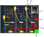
도면 1은 수배전반 내 HFCT와, 스위칭 박스, 정밀 진단 장치, 및 데이터 기록형 진단 장치의 설치 위치를 도시한 도면,
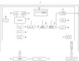
도면 2는 데이터 기록형 진단 장치의 제어 블록도,
도면 3은 제1 필터의 제어 회로도,
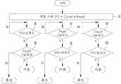
도면 4는 데이터 기록형 진단 장치가 측정한 부분 방전량을 분석하여 사고 위험 메시지나 주의 메시지를 전송하는 절차를 3가지 경우에 대하여 정리한 플로우 챠트,
도면 5는 정밀 진단 장치의 제어 블록도.1 is a view showing installation positions of a HFCT in a switchboard, a switching box, a precise diagnosis device and a data recording type diagnosis device,
2 is a control block diagram of a data recording type diagnostic apparatus;
3 is a control circuit diagram of the first filter,
4 is a flow chart summarizing the procedure for analyzing the partial discharge amount measured by the data recording diagnostic apparatus and transmitting an accident risk message or a caution message in three cases,
FIG. 5 is a control block diagram of a fine diagnostic apparatus. FIG.
이하, 첨부된 도면을 참조하여 본 발명을 자세히 설명한다.Hereinafter, the present invention will be described in detail with reference to the accompanying drawings.
본 발명에 따른 HFCT가 내장된 진단 장치를 적용한 배전반은 수배전반(1) 내 각 구간별 활선 상태의 전기 선로나 수배전반(1)에 설치된 기기별 접지부, 또는 부스바를 절연 물질로 둘러싸 수배전반(1)과 부스바 사이를 절연시키는 부싱부에서 누설되는 부분 방전량(PD: Partial Discharge)에 상응하는 전압 신호를 출력하는 부분 방전량 감지 센서(3)와; 상기 부분 방전량 감지 센서(3)로부터 출력되는 아날로그 신호를 디지털 값으로 변환하고 상기 디지털 값을 부분 방전량으로 환산하여 수배전반(1) 내 각 구간별 전기 선로나 수배전반(1)에 설치된 기기별 접지 선로, 또는 부스바를 절연 물질로 둘러싸 수배전반(1)과 부스바 사이를 절연시키는 부싱부로부터 발생 된 부분 방전량을 측정하는 데이터 기록형 진단 장치(5); 상기 데이터 기록형 진단 장치(5)에 의해 수배전반(1) 내 부분 방전량이 감지되었을 때 상기 부분 방전량 감지 센서(3)를 이용하여 데이터 기록형 진단 장치(5)보다 더 정밀하게 부분 방전량을 측정하여 수배전반(1) 내 부분 방전이 발생 된 위치를 파악하는 정밀 진단 장치(7); 및 상기 데이터 기록형 진단 장치(5)에 의해 수배전반(1) 내 부분 방전이 측정되었을 때 데이터 기록형 진단 장치(5)에 연결된 부분 방전량 감지 센서(3)를 정밀 진단 장치(7)에 연결시키는 스위칭 박스(9)로 이루어질 수 있다.The switchboard to which the diagnosis apparatus with the HFCT built therein according to the present invention is applied can be realized by connecting the electric line or the grounding unit of each device in the switchboard 1 or the grounding unit of the switchboard 1 surrounded by the insulating material, A partial discharge
상기 부분 방전량 감지 센서(3)는 2개 이상의 HFCT(11)(High Frequency Current Transformer)로 이루어짐이 바람직하다.It is preferable that the partial discharge
상기 데이터 기록형 진단 장치(5)는 도면 2에 도시한 바와 같이, 상기 2개 이상의 HFCT(11)로부터 출력된 전기 신호를 입력받는 제1 신호 입력부(13)와, 상기 제1 신호 입력부(13)를 통해 입력된 HFCT(11)로부터 출력된 전기 신호 중 불필요한 고주파 노이즈 성분을 제거하는 제1 필터(15), 상기 제1 필터(15)로부터 출력되는 아날로그 전압을 디지털값으로 변환하는 제1 A/D 변환부(17), 및 상기 제1 A/D 변환부(17)로부터 출력되는 디지털 값을 부분 방전량으로 환산하는 제1 제어부(19)를 더 포함한다.As shown in FIG. 2, the data recording type
상기 제1 필터(15)는 예를 들어 고주파 성분을 감쇄하는 로우 패스 필터를 사용할 수 있는데, 상기 로우 패스 필터는 단순히 RC 로우 패스 필터나, 베쎌(Bessel) 필터, 버터워스(Butterworth) 필터, 또는 쉐비쉐브(Chebyshev) 필터를 사용할 수 있다.For example, the
상기 제1 필터(15)는 도면 3에 도시한 제1 실시 예와 같이, 3 스테이지(Stage)로 이루어진 로우 패스 베쎌 살렌 키 필터(Low pass Bessel Sallen-Key filter)를 사용할 수 있는데, 상기 로우 패스 베쎌 살렌 키 필터는 HFCT(11)로부터 출력되는 고주파 성분을 5차(Order) 감쇄시킨다.The
상기 로우 패스 베쎌 살렌 키 필터는 도면 3에 도시한 바와 같이, 일단이 HFCT(11)의 출력단에 연결되고 타단이 제1 오피 앰프(75)의 비반전 입력단에 연결된 제1 저항(77)과, 일단이 제1 저항(77)의 타단에 연결되고 타단이 접지된 제1 커패시터(79), 및 반전 입력 단자와 출력 단자가 연결된 제1 오피 앰프(75)로 구성된 제1 스테이지 필터를 포함한다.As shown in FIG. 3, the lowpass Bessel Salen key filter includes a
상기 제1 스테이지 필터는 HFCT(11)로부터 입력된 신호 중
또한, 상기 로우 패스 베쎌 살렌 키 필터는 도면 3에 도시한 바와 같이, 일단이 제1 스테이지 필터의 출력단에 연결된 제2 저항(81)과, 일단이 제2 저항(81)의 타단에 연결되고 타단이 제2 오피 앰프(83)의 비반전 입력단에 연결된 제3 저항(85), 일단이 제2 오피 앰프(83)의 비반전 입력단에 연결되고 타단이 접지된 제2 커패시터(87), 일단이 제2 저항(81)의 타단에 연결되고 타단이 제2 오피 앰프(83)의 출력단에 연결된 제3 커패시터(89), 반전 입력단과 출력단이 연결된 제2 오피 앰프(83)로 구성된 제2 스테이지 필터를 구비한다.3, the lowpass Bessel Salen key filter includes a
상기 제2 스테이지 필터는 제1 스테이지 필터로부터 출력된 신호 중
또한, 상기 로우 패스 베쎌 살렌 키 필터는 도면 3에 도시한 바와 같이, 일단이 제2 스테이지 필터의 출력단에 연결된 제4 저항(91)과, 일단이 제4 저항(91)의 타단에 연결되고 타단이 제3 오피 앰프(93)의 비반전 입력단에 연결된 제5 저항(95), 일단이 제3 오피 앰프(93)의 비반전 입력단에 연결되고 타단이 접지된 제4 커패시터(97), 일단이 제4 저항(91)의 타단에 연결되고 타단이 제3 오피 앰프(93)의 출력단에 연결된 제5 커패시터(99), 반전 입력단과 출력단이 연결된 제3 오피 앰프(93)로 구성된 제3 스테이지 필터를 구비한다.3, the lowpass Bessel salen key filter includes a
상기 제3 스테이지 필터는 상기 제2 스테이지 필터로부터 출력된 신호 중
또, 상기 데이터 기록형 진단 장치(5)는 초과시 사고 위험 메시지나 주의 메시지를 전송하는 부분 방전량의 상한값이나, 부분 방전이 일어난 횟수, 또는 부분 방전량의 피크(Peak)치를 설정하거나 측정된 부분 방전량을 기록하도록 명령하는 제1 디지털 입력 인터페이스(23)와, 상기 제1 제어부(19)에 의해 환산된 부분 방전량이 부분 방전량의 상한값을 초과하였는지, 또는 부분 방전이 일어난 횟수가 기준치를 초과하였는지, 또는 측정된 부분 방전량이 설정된 피크(Peak)치를 초과하였는지 점검하는 제1 부분 방전량 분석부(25), 및 측정된 부분 방전량을 상위 시스템으로 전송하여 상위 시스템이 부분 방전량을 모니터링 하도록 하거나 상위 시스템의 구동 명령을 제1 제어부(19)로 전달하여 제1 제어부(19)가 부분 방전량을 측정하도록 하는 제1 통신 인터페이스(27)를 더 포함한다.The data recording type
또, 상기 데이터 기록형 진단 장치(5)는 제1 제어부(19)에 부분 방전량을 측정하거나 측정된 부분 방전량을 기록하기 위한 운영 프로그램을 다운로드 할 수 있도록 제1 다운로더(29)와, 제1 제어부(19)에 기준 클락(Clock) 신호를 제공하는 제1 클락 신호 발생부(31), 상기 제1 제어부(19)가 부분 방전량을 측정하거나 측정된 부분 방전량을 기록하기 위한 운용 프로그램이 저장되는 제1 메모리부(33), 상기 제1 제어부(19)에 의해 측정된 부분 방전량을 저장하는 제2 메모리부(35), 및 상기 데이터 기록형 진단 장치(5)가 최초 부팅(Booting)될 때 초기 환경 설정 파일을 제공하는 제1 NVRAM(37)이 부가 장착될 수 있다.The data recording type
또, 상기 데이터 기록형 진단 장치(5)는 제1 제어부(19)에 의해 측정된 부분 방전량을 표시하거나 초과시 사고 위험 메시지나 주의 메시지를 전송하는 부분 방전량의 상한값이나, 부분 방전이 일어난 횟수, 또는 부분 방전량의 피크(Peak)치를 표시하는 제1 표시부(39)를 더 포함한다.In addition, the data recording type
또, 상기 데이터 기록형 진단 장치(5)는 입력된 220V 교류 전압을 저전압으로 낮춘 다음 정류하여 저전압 직류 전원으로 변환하는 제1 전원 공급부(41)를 더 포함한다.The data recording type
상기와 같은 구성으로 이루어진 상기 데이터 기록형 진단 장치(5)는 도면 4에 도시한 바와 같이, 시간에 따른 부분 방전량과 부분 방전이 일어난 횟수, 및 부분 방전량의 피크(Peak)치를 측정한다.(S1)As shown in FIG. 4, the data recording type
상기 데이터 기록형 진단 장치(5)는 측정된 부분 방전량이 설정된 부분 방전량의 상한값보다 크고(S3) 부분 방전이 일어난 횟수가 설정 기준치를 초과하였을 때 제1 표시부(39)나 제1 통신 인터페이스(27)를 통해 사고 위험 메시지를 전송할 수 있다.(S5)When the measured partial discharge amount is larger than the upper limit value of the set partial discharge amount (S3) and the number of times the partial discharge has occurred exceeds the set reference value, the data recording type
반면, 측정된 부분 방전량이 설정된 부분 방전량의 상한값보다 크지만,(S3) 부분 방전이 일어난 횟수가 설정 기준치를 초과하지 않았을 때에는 제1 표시부(39)나 제1 통신 인터페이스(27)를 통해 주의 메시지를 전송할 수 있다.On the other hand, when the measured partial discharge amount is larger than the upper limit value of the set partial discharge amount, (S3) when the number of times that the partial discharge has occurred does not exceed the set reference value, Message can be transmitted.
또한, 상기 데이터 기록형 진단 장치(5)는 측정된 부분 방전량의 피크(Peak)치가 설정된 부분 방전량의 피크(Peak)치보다 크고(S7) 측정된 부분 방전량이 설정된 부분 방전량의 상한값보다 클 경우(S9) 제1 표시부(39)나 제1 통신 인터페이스(27)를 통해 사고 위험 메시지를 전송할 수 있다.The peak value of the measured partial discharge amount is larger than the peak value of the set partial discharge amount (S7), and the measured partial discharge amount is smaller than the upper limit value of the set partial discharge amount (S9), it is possible to transmit an accident risk message through the
반면, 측정된 부분 방전량의 피크(Peak)치가 설정된 부분 방전량의 피크(Peak)치보다 크지만, 측정된 부분 방전량이 설정된 부분 방전량의 상한값보다 크지 않을 경우 제1 표시부(39)나 제1 통신 인터페이스(27)를 통해 주의 메시지를 전송할 수 있다.On the other hand, if the peak value of the measured partial discharge amount is larger than the peak value of the set partial discharge amount but the measured partial discharge amount is not larger than the upper limit value of the set partial discharge amount, Lt; RTI ID = 0.0 > 1 < / RTI >
또, 상기 데이터 기록형 진단 장치(5)는 부분 방전이 일어난 횟수가 설정된 기준치를 초과하였고,(S11) 측정된 부분 방전량이 설정된 부분 방전량의 상한값보다 클 경우 제1 표시부(39)나 제1 통신 인터페이스(27)를 통해 사고 위험 메시지를 전송할 수 있다.(S13)When the number of times of partial discharge has exceeded the set reference value and the measured partial discharge amount is larger than the upper limit value of the set partial discharge amount, the data recording type
반면, 부분 방전이 일어난 횟수가 설정된 기준치를 초과하였지만, 측정된 부분 방전량이 설정된 부분 방전량의 상한값보다 크지 않을 경우 표시부나 제1 통신 인터페이스(27)를 통해 주의 메시지를 전송할 수 있다.On the other hand, if the number of times the partial discharge has exceeded the set reference value but the measured partial discharge amount is not larger than the upper limit value of the set partial discharge amount, the attention message can be transmitted through the display unit or the
상기 정밀 진단 장치(7)는 도면 5에 도시한 바와 같이, 상기 스위칭 박스(9)를 거쳐 2개 이상의 HFCT(11)로부터 전기 신호를 입력받는 제2 신호 입력부(43)와, 상기 제2 신호 입력부(43)를 통해 입력된 HFCT(11)로부터 출력된 전기 신호 중 불필요한 고주파 노이즈 성분을 제거하는 제2 필터(45), 상기 제2 필터(45)로부터 출력되는 아날로그 전압을 디지털값으로 변환하는 제2 A/D 변환부(47), 및 상기 제2 A/D 변환부(47)로부터 출력되는 디지털 값을 부분 방전량으로 환산하는 제2 제어부(49)를 더 포함한다.As shown in FIG. 5, the
상기 제2 필터(45)는 예를 들어, 고주파 성분을 감쇄하는 로우 패스 필터를 사용할 수 있는데, 상기 로우 패스 필터는 단순히 RC 로우 패스 필터나, 베쎌(Bessel) 필터, 버터워스(Butterworth) 필터, 또는 쉐비쉐브(Chebyshev) 필터를 사용할 수 있다.For example, the
상기 정밀 진단 장치(7)의 제2 A/D 변환부(47)의 분해능과 샘플링 레이트(Sampling rate)는 데이터 기록형 진단 장치(5)의 제1 A/D 변환부(17)의 분해능과 샘플링 레이트보다 높아 HFCT(11)로부터 출력된 전기 신호를 보다 정밀하게 잡아낼 수 있다.The resolution and the sampling rate of the second A /
또한, 상기 정밀 진단 장치(7)는 초과시 사고 위험 메시지나 주의 메시지를 전송하는 부분 방전량의 상한값이나, 부분 방전이 일어난 횟수, 또는 부분 방전량의 피크(Peak)치를 설정하거나 측정된 부분 방전량을 기록하도록 명령하는 제2 디지털 입력 인터페이스(53)와, 제2 제어부(49)에 의해 환산된 부분 방전량을 이용하여 부분 방전이 발생된 위치를 추적하는 부분 방전 위치 분석부(55), 및 측정된 부분 방전량을 상위 시스템으로 전송하거나 상위 시스템의 구동 명령을 제2 제어부(49)로 전달하여 제2 제어부(49)가 부분 방전량을 측정하도록 하는 제2 통신 인터페이스(57)를 더 포함한다.Further, the above-described
또, 상기 정밀 진단 장치(7)는 제2 제어부(49)에 부분 방전량을 측정하거나 측정된 부분 방전량을 기록하기 위한 운영 프로그램을 다운로드할 수 있도록 제2 다운로더(59)와, 제2 제어부(49)에 기준 클락(Clock) 신호를 제공하는 제2 클락 신호 발생부(61), 상기 제2 제어부(49)가 부분 방전량을 측정하거나 측정된 부분 방전량을 기록하기 위한 운용 프로그램이 저장되는 제3 메모리부(63), 상기 제2 제어부(49)에 의해 측정된 부분 방전량을 저장하는 제4 메모리부(65), 및 상기 데이터 기록형 진단 장치(5)가 최초 부팅(Booting)될 때 초기 환경 설정 파일을 제공하는 제2 NVRAM(67)이 부가 장착될 수 있다.The fine
또, 상기 정밀 진단 장치(7)는 도면 4에 도시한 바와 같이, 제2 제어부에 의해 측정된 부분 방전량을 표시하는 제2 표시부(69)를 더 포함한다.The
또, 상기 정밀 진단 장치(7)는 입력된 220V 교류 전압을 저전압으로 낮춘 다음 정류하여 저전압 직류 전원으로 변환하는 제2 전원 공급부(71)를 더 포함한다.The precision
또, 상기 정밀 진단 장치(7)는 부분 방전이 수배전반(1) 내부 전기 선로나 기기로부터 발생 되었는지 또는 수배전반(1) 외부로부터 유입되었는지 판단하는 부분 방전 유입 위치 판단부(73)를 더 포함한다.The
이러한 구성으로 이루어진 본 발명에 따른 HFCT가 내장된 진단 장치를 적용한 배전반은 1차적으로 수배전반(1) 내 각 구간별 전기 선로나 수배전반(1)에 설치된 기기별 접지 선로, 또는 부스바를 절연 물질로 둘러싸 수배전반(1)과 부스바 사이를 절연시키는 부싱부로부터 누설되는 부분 방전량과 부분 방전이 일어난 횟수, 및 부분 방전의 피크치(Peak)를 측정한다.The switchboard to which the diagnosis device with the HFCT built in according to the present invention is applied is configured such that the electric line for each section in the switchboard 1 or the ground line for each device installed in the switchboard 1 or the busbar is surrounded by an insulating material The amount of partial discharge, the number of partial discharge, and the peak value of partial discharge leaked from the bushing portion that insulates the busbar 1 from the busbar 1 are measured.
측정 결과, 부분 방전량과 부분 방전이 일어난 횟수가 설정치를 초과하였거나, 부분 방전량의 피크치와 부분 방전량이 설정치를 초과했을 경우 정밀 진단 장치(7)를 이용하여 2차적으로 부분 방전량을 측정함으로써 부분 방전이 일어난 곳이나 부분 방전의 외부 유입 여부를 검출하게 된다.When the partial discharge amount and the number of times of the partial discharge exceed the set value, or when the peak value and the partial discharge amount of the partial discharge amount exceed the set value, the partial discharge amount is secondarily measured using the precision diagnosis device (7) It is detected whether the partial discharge occurs or whether the partial discharge is externally introduced.
따라서, 본 발명에 따른 HFCT가 내장된 진단 장치를 적용한 배전반은 수배전반(1) 내 절연 성능 저하에 따른 부분 방전 발생시 이를 감지하여 사고를 미연에 방지함으로써 경제 손실을 감소시킬 수 있다.Accordingly, the present invention can reduce an economic loss by detecting an occurrence of a partial discharge due to deterioration of insulation performance in the switchboard 1, thereby preventing an accident.
또한, 본 발명은 수배전반(1)의 각 구간별, 각 기기별로 부분 방전의 발생 유무를 확인할 수 있고, 부분 방전이 수배전반(1)의 내부에서 발생 되었는지, 또는 수배전반(1)의 외부에서 유입되었는지 판별할 수 있다.The present invention can confirm whether partial discharge has occurred for each section of the switchboard 1 and whether or not partial discharge has occurred for each device and whether or not the partial discharge has occurred inside the switchboard 1 or entered from outside the switchboard 1 Can be distinguished.
1. 수배전반 3. 부분 방전량 감지 센서
5. 데이터 기록형 진단 장치 7. 정밀 진단 장치
9. 스위칭 박스 11. HFCT
13. 제1 신호 입력부 15. 제1 필터
17. 제1 A/D 변환부 19. 제1 제어부
23. 제1 디지털 입력 인터페이스 25. 제1 부분 방전량 분석부
29. 제1 다운로더 31. 제1 클락 신호 발생부
33. 제1 메모리부 35. 제2 메모리부
37. 제1 NVRAM 39. 제1 표시부
41. 제1 전원 공급부 43. 제2 신호 입력부
45. 제2 필터 47. 제2 A/D 변환부
53. 제2 디지털 입력 인터페이스 55. 부분 방전 위치 분석부
57. 제2 통신 인터페이스 59. 제2 다운로더
61. 제2 클락 신호 발생부 63. 제3 메모리부
65. 제4 메모리부 67. 제2 NVRAM
69. 제2 표시부 71. 제2 전원 공급부
73. 부분 방전 유입 위치 판단부 75. 제1 오피 앰프
77. 제1 저항 79. 제1 커패시터
81. 제2 저항 83. 제2 오피 앰프
85. 제3 저항 87. 제2 커패시터
89. 제3 커패시터 91. 제4 저항
93. 제3 오피 앰프 95. 제5 저항
97. 제4 커패시터 99. 제5 커패시터1.
5. Data recording type
9.
13. First
17. First A /
23. First
29.
33. A
37.
41.
45. A
53. Second
57.
61. Second
65.
69.
73. Partial discharge inflow
77.
81.
85.
89.
93.
97.
Claims (4)
Translated fromKorean상기 부분 방전량 감지 센서(3)로부터 출력되는 아날로그 신호를 디지털 값으로 변환하고 상기 디지털 값을 부분 방전량으로 환산하여 수배전반(1) 내 각 구간별 전기 선로나 수배전반(1)에 설치된 기기별 접지 선로, 또는 부스바를 절연 물질로 둘러싸 수배전반(1)과 부스바 사이를 절연시키는 부싱부로부터 발생 된 부분 방전량을 측정하는 데이터 기록형 진단 장치(5);
상기 데이터 기록형 진단 장치(5)에 의해 수배전반(1) 내 부분 방전량이 감지되었을 때 상기 부분 방전량 감지 센서(3)를 이용하여 데이터 기록형 진단 장치(5)보다 더 정밀하게 부분 방전량을 측정하여 수배전반(1) 내 부분 방전이 발생 된 위치를 파악하는 정밀 진단 장치(7);
및 상기 데이터 기록형 진단 장치(5)에 의해 수배전반(1) 내 부분 방전이 측정되었을 때 데이터 기록형 진단 장치(5)에 연결된 부분 방전량 감지 센서(3)를 정밀 진단 장치(7)에 연결시키는 스위칭 박스(9)로 이루어지고,
상기 부분 방전량 감지 센서(3)는 2개 이상의 HFCT(11)(High Frequency Current Transformer)이고,
상기 데이터 기록형 진단 장치(5)는 상기 2개 이상의 HFCT(11)로부터 출력된 전기 신호를 입력받는 제1 신호 입력부(13)와, 상기 제1 신호 입력부(13)를 통해 입력된 HFCT(11)로부터 출력된 전기 신호 중 불필요한 고주파 노이즈 성분을 제거하는 제1 필터(15), 상기 제1 필터(15)로부터 출력되는 아날로그 전압을 디지털값으로 변환하는 제1 A/D 변환부(17), 및 상기 제1 A/D 변환부(17)로부터 출력되는 디지털 값을 부분 방전량으로 환산하는 제1 제어부(19)를 더 포함하며,
상기 데이터 기록형 진단 장치(5)는 초과시 사고 위험 메시지나 주의 메시지를 전송하는 부분 방전량의 상한값이나, 부분 방전이 일어난 횟수, 또는 부분 방전량의 피크(Peak)치를 설정하거나 측정된 부분 방전량을 기록하도록 명령하는 제1 디지털 입력 인터페이스(23)와,
상기 제1 제어부(19)에 의해 환산된 부분 방전량이 부분 방전량의 상한값을 초과하였는지, 또는 부분 방전이 일어난 횟수가 기준치를 초과하였는지, 또는 측정된 부분 방전량이 설정된 피크(Peak)치를 초과하였는지 점검하는 제1 부분 방전량 분석부(25),
및 측정된 부분 방전량을 상위 시스템으로 전송하여 상위 시스템이 부분 방전량을 모니터링 하도록 하거나 상위 시스템의 구동 명령을 제1 제어부(19)로 전달하여 제1 제어부(19)가 부분 방전량을 측정하도록 하는 제1 통신 인터페이스(27)를 더 포함하고,
상기 정밀 진단 장치(7)는 상기 스위칭 박스(9)를 거쳐 2개 이상의 HFCT(11)로부터 전기 신호를 입력받는 제2 신호 입력부(43)와, 상기 제2 신호 입력부(43)를 통해 입력된 HFCT(11)로부터 출력된 전기 신호 중 불필요한 고주파 노이즈 성분을 제거하는 제2 필터(45), 상기 제2 필터(45)로부터 출력되는 아날로그 전압을 디지털값으로 변환하는 제2 A/D 변환부(47), 및 상기 제2 A/D 변환부(47)로부터 출력되는 디지털 값을 부분 방전량으로 환산하는 제2 제어부(49)를 더 포함하며,
상기 정밀 진단 장치(7)의 제2 A/D 변환부(47)의 분해능과 샘플링 레이트(Sampling rate)는 데이터 기록형 진단 장치(5)의 제1 A/D 변환부(17)의 분해능과 샘플링 레이트보다 높고,
상기 제2 제어부(49)에 의해 환산된 부분 방전량을 이용하여 부분 방전이 발생된 위치를 추적하는 부분 방전 위치 분석부(55)와,
및 측정된 부분 방전량을 상위 시스템으로 전송하거나 상위 시스템의 구동 명령을 제2 제어부(49)로 전달하여 제2 제어부(49)가 부분 방전량을 측정하도록 하는 제2 통신 인터페이스(57)를 더 포함하는 것을 특징으로 하는 HFCT가 내장된 진단 장치를 적용한 배전반.
(1), a grounding part for each equipment installed in a live wire or a switchboard (1) for each section in the switchboard (1), or a partly leaked part in a bushing part for insulating the busbar A partial discharge amount detecting sensor 3 for outputting a voltage signal corresponding to a total amount of discharge (PD);
(1), and converts the analog value output from the partial discharge amount detecting sensor (3) into a digital value and converts the digital value into a partial discharge amount, A data recording type diagnostic apparatus 5 for measuring a partial discharge amount generated from a bushing portion which surrounds a line or a bus bar with an insulating material and insulates the busbar 1 from the bus bar;
When the partial discharge amount in the switchboard 1 is detected by the data recording type diagnostic apparatus 5, the partial discharge amount detection sensor 3 is used to more accurately detect the partial discharge amount A precise diagnosis device 7 for measuring the position where the partial discharge in the switchboard 1 is measured;
And a partial discharge amount detection sensor (3) connected to the data recording type diagnostic device (5) when the partial discharge in the switchgear (1) is measured by the data recording type diagnostic device And a switching box (9)
The partial discharge amount detection sensor 3 is at least two HFCT 11 (High Frequency Current Transformer)
The data recording type diagnostic apparatus 5 includes a first signal input unit 13 for receiving an electric signal output from the at least two HFCTs 11 and a second signal input unit 13 for receiving an HFCT 11 A first A / D converter 17 for converting an analog voltage output from the first filter 15 into a digital value, a second A / D converter 17 for converting an analog voltage output from the first filter 15 into a digital value, And a first controller (19) for converting the digital value output from the first A / D converter (17) into a partial discharge amount,
The data recording type diagnostic apparatus 5 sets the peak value of the partial discharge amount, the number of times of the partial discharge, or the peak discharge amount of the partial discharge amount, which transmits the accident risk message or the caution message, A first digital input interface 23 for instructing to record an input signal,
It is checked whether or not the partial discharge amount converted by the first control unit 19 exceeds the upper limit value of the partial discharge amount or the number of times that the partial discharge has occurred exceeds the reference value or the measured partial discharge amount exceeds the set peak value A first partial discharge amount analyzer 25,
And the measured partial discharge amount to the upper system so that the upper system monitors the partial discharge amount or transmits the drive command of the upper system to the first control unit 19 so that the first control unit 19 measures the partial discharge amount Further comprising a first communication interface (27)
The precision diagnostic apparatus 7 includes a second signal input unit 43 for receiving an electric signal from two or more HFCTs 11 via the switching box 9, A second filter 45 for removing unnecessary high frequency noise components from the electrical signals output from the HFCT 11, a second A / D converter (not shown) for converting the analog voltage output from the second filter 45 into a digital value 47), and a second controller (49) for converting the digital value output from the second A / D converter (47) into a partial discharge amount,
The resolution and the sampling rate of the second A / D converter 47 of the above-described precise diagnostic apparatus 7 are determined based on the resolution of the first A / D converter 17 of the data recording type diagnostic apparatus 5 Higher than the sampling rate,
A partial discharge position analyzer 55 for tracking the position where the partial discharge is generated by using the partial discharge amount converted by the second controller 49,
And a second communication interface 57 for transmitting the measured partial discharge amount to the upper system or transmitting the drive command of the upper system to the second control unit 49 so that the second control unit 49 measures the partial discharge amount Wherein the HFCT is installed in the cabinet.
상기 정밀 진단 장치(7)는 부분 방전이 수배전반(1) 내부 전기 선로나 기기로부터 발생 되었는지 또는 수배전반(1) 외부로부터 유입되었는지 판단하는 부분 방전 유입 위치 판단부(73)를 더 포함하는 것을 특징으로 하는 HFCT가 내장된 진단 장치를 적용한 배전반.The method according to claim 1,
The precise diagnosis apparatus 7 further includes a partial discharge inflow position determining unit 73 for determining whether the partial discharge is generated from the internal electric line or apparatus or from the outside of the switchboard 1 A switchboard to which a diagnostic device with built-in HFCT is applied.
Priority Applications (1)
| Application Number | Priority Date | Filing Date | Title |
|---|---|---|---|
| KR1020160041408AKR101641515B1 (en) | 2016-04-05 | 2016-04-05 | The distribution panel including a diagnosis apparatus using HFCT |
Applications Claiming Priority (1)
| Application Number | Priority Date | Filing Date | Title |
|---|---|---|---|
| KR1020160041408AKR101641515B1 (en) | 2016-04-05 | 2016-04-05 | The distribution panel including a diagnosis apparatus using HFCT |
Publications (1)
| Publication Number | Publication Date |
|---|---|
| KR101641515B1true KR101641515B1 (en) | 2016-07-22 |
Family
ID=56681427
Family Applications (1)
| Application Number | Title | Priority Date | Filing Date |
|---|---|---|---|
| KR1020160041408AActiveKR101641515B1 (en) | 2016-04-05 | 2016-04-05 | The distribution panel including a diagnosis apparatus using HFCT |
Country Status (1)
| Country | Link |
|---|---|
| KR (1) | KR101641515B1 (en) |
Cited By (7)
| Publication number | Priority date | Publication date | Assignee | Title |
|---|---|---|---|---|
| KR101892867B1 (en)* | 2017-09-19 | 2018-08-28 | 홍영일 | The air circulation real-time monitoring system of a machine tool's interior through image analysis |
| WO2020179976A1 (en)* | 2019-03-05 | 2020-09-10 | 엘에스일렉트릭 주식회사 | System and apparatus for monitoring partial discharges in switchboards |
| KR102221399B1 (en)* | 2019-11-18 | 2021-02-26 | 이태희 | PD measuring device with multi-measurement input conversion |
| US20210373065A1 (en)* | 2018-12-12 | 2021-12-02 | Hitachi, Ltd. | Partial discharge detection apparatus and partial discharge detection method |
| WO2023003242A1 (en)* | 2021-07-19 | 2023-01-26 | 효성중공업 주식회사 | Battery fire prevention and diagnosis system |
| KR20250062320A (en) | 2023-10-30 | 2025-05-08 | 한국전기연구원 | Power equipment diagnostic system protection device within the distribution board |
| KR20250062321A (en) | 2023-10-30 | 2025-05-08 | 한국전기연구원 | Device and method for diagnosing power equipment insulators in switchboards and estimating faulty power equipment |
Citations (6)
| Publication number | Priority date | Publication date | Assignee | Title |
|---|---|---|---|---|
| JPH08105928A (en)* | 1994-10-05 | 1996-04-23 | Takaoka Electric Mfg Co Ltd | Partial discharge intensity measuring device |
| JPH08152453A (en)* | 1994-11-28 | 1996-06-11 | Sumitomo Electric Ind Ltd | Partial discharge measurement method |
| KR20100022785A (en) | 2008-08-20 | 2010-03-03 | 한전케이디엔주식회사 | System and method for measuaring partial discharge for power cable |
| KR20130047418A (en) | 2011-10-31 | 2013-05-08 | 한국전력공사 | Apparatus and method for diagnosing partial discharge of high voltage facilities using a plurality of sensors |
| KR20150051707A (en)* | 2013-11-05 | 2015-05-13 | 한국전력공사 | Diagnosis apparatus of partial discharge for completion test of underground transmission cable |
| KR101553005B1 (en) | 2015-04-20 | 2015-10-01 | 지투파워 (주) | A partial discharge monitoring and diagnosis system for power devices |
- 2016
- 2016-04-05KRKR1020160041408Apatent/KR101641515B1/enactiveActive
Patent Citations (6)
| Publication number | Priority date | Publication date | Assignee | Title |
|---|---|---|---|---|
| JPH08105928A (en)* | 1994-10-05 | 1996-04-23 | Takaoka Electric Mfg Co Ltd | Partial discharge intensity measuring device |
| JPH08152453A (en)* | 1994-11-28 | 1996-06-11 | Sumitomo Electric Ind Ltd | Partial discharge measurement method |
| KR20100022785A (en) | 2008-08-20 | 2010-03-03 | 한전케이디엔주식회사 | System and method for measuaring partial discharge for power cable |
| KR20130047418A (en) | 2011-10-31 | 2013-05-08 | 한국전력공사 | Apparatus and method for diagnosing partial discharge of high voltage facilities using a plurality of sensors |
| KR20150051707A (en)* | 2013-11-05 | 2015-05-13 | 한국전력공사 | Diagnosis apparatus of partial discharge for completion test of underground transmission cable |
| KR101553005B1 (en) | 2015-04-20 | 2015-10-01 | 지투파워 (주) | A partial discharge monitoring and diagnosis system for power devices |
Cited By (12)
| Publication number | Priority date | Publication date | Assignee | Title |
|---|---|---|---|---|
| KR101892867B1 (en)* | 2017-09-19 | 2018-08-28 | 홍영일 | The air circulation real-time monitoring system of a machine tool's interior through image analysis |
| US20210373065A1 (en)* | 2018-12-12 | 2021-12-02 | Hitachi, Ltd. | Partial discharge detection apparatus and partial discharge detection method |
| US11644498B2 (en)* | 2018-12-12 | 2023-05-09 | Hitachi, Ltd. | Partial discharge detection apparatus and partial discharge detection method |
| WO2020179976A1 (en)* | 2019-03-05 | 2020-09-10 | 엘에스일렉트릭 주식회사 | System and apparatus for monitoring partial discharges in switchboards |
| KR20200106653A (en)* | 2019-03-05 | 2020-09-15 | 엘에스일렉트릭(주) | System and Apparatus for Monitoring of Partial Discharge in Switchboard |
| KR102189498B1 (en)* | 2019-03-05 | 2020-12-11 | 엘에스일렉트릭(주) | System and Apparatus for Monitoring of Partial Discharge in Switchboard |
| CN113508504A (en)* | 2019-03-05 | 2021-10-15 | Ls电气株式会社 | System and device for monitoring partial discharge in distribution board |
| US11953552B2 (en) | 2019-03-05 | 2024-04-09 | Ls Electric Co., Ltd. | System and apparatus for monitoring partial discharges in switchboards |
| KR102221399B1 (en)* | 2019-11-18 | 2021-02-26 | 이태희 | PD measuring device with multi-measurement input conversion |
| WO2023003242A1 (en)* | 2021-07-19 | 2023-01-26 | 효성중공업 주식회사 | Battery fire prevention and diagnosis system |
| KR20250062320A (en) | 2023-10-30 | 2025-05-08 | 한국전기연구원 | Power equipment diagnostic system protection device within the distribution board |
| KR20250062321A (en) | 2023-10-30 | 2025-05-08 | 한국전기연구원 | Device and method for diagnosing power equipment insulators in switchboards and estimating faulty power equipment |
Similar Documents
| Publication | Publication Date | Title |
|---|---|---|
| KR101641515B1 (en) | The distribution panel including a diagnosis apparatus using HFCT | |
| KR101070832B1 (en) | Anomaly Detection Method of Switchgear with Self-diagnosis Function | |
| JP4797175B2 (en) | Method and apparatus for measuring partial discharge charge | |
| KR101402887B1 (en) | System and method of monitoring GIS partial discharge having analyzing function linked time and frequency domain, local unit therefor | |
| CN103675623B (en) | GIS partial discharge detection method and system under a kind of surge voltage | |
| EP2466324A1 (en) | Combined measuring and detection system | |
| US9146268B2 (en) | Method and device for monitoring a sheath voltage arrester of a cable system | |
| KR102231150B1 (en) | Bushing diagnostic system | |
| CN101598762A (en) | A sensor and a device for monitoring partial discharge of a gas-insulated metal-enclosed switch | |
| KR20220126381A (en) | Voltage measuring device for high-voltage power equipment and high-voltage power equipment having the same | |
| CN112912741B (en) | State analysis of an electrical operating device | |
| CN106249054B (en) | Capacitance type voltage transformer and integrated detection sensor thereof | |
| JP2009210541A (en) | Partial discharge detection method and partial discharge detector of epoxy-insulated electrical equipment | |
| EP2209014B1 (en) | Partial corona discharge detection | |
| KR101843792B1 (en) | Method for deciding partial discharge for power equipment | |
| CN110736922B (en) | Device and method for measuring switch-on pre-breakdown time | |
| KR20230073641A (en) | Sensor device for bushing tab adaptor and System for dignozing bushing online using the same | |
| CN204649952U (en) | Based on the bushing shell for transformer monitoring device detection platform of synchro measure | |
| WO2021069878A1 (en) | Partial discharge monitoring device, system and method for a substation asset provided with a voltage presence indication system (vpis) | |
| JP7739417B2 (en) | Gas-insulated surge arresters and gas-insulated surge arrester monitoring systems | |
| CN102449493A (en) | Device for diagnosing measurement objects using a measurement voltage | |
| KR102413919B1 (en) | Partial discharge monitoring system and patial discharge monitoring method | |
| CN115867814B (en) | High-voltage instrument transformer and method for identifying partial discharge | |
| Bucci et al. | Improving the Power System safety in Hospitals by means of periodical SFRA tests on Medical Isolation Transformers | |
| RU2818652C1 (en) | Method for diagnostics of cable power transmission line and device for its implementation |
Legal Events
| Date | Code | Title | Description |
|---|---|---|---|
| PA0109 | Patent application | Patent event code:PA01091R01D Comment text:Patent Application Patent event date:20160405 | |
| PA0201 | Request for examination | ||
| PA0302 | Request for accelerated examination | Patent event date:20160414 Patent event code:PA03022R01D Comment text:Request for Accelerated Examination Patent event date:20160405 Patent event code:PA03021R01I Comment text:Patent Application | |
| E902 | Notification of reason for refusal | ||
| PE0902 | Notice of grounds for rejection | Comment text:Notification of reason for refusal Patent event date:20160530 Patent event code:PE09021S01D | |
| E701 | Decision to grant or registration of patent right | ||
| PE0701 | Decision of registration | Patent event code:PE07011S01D Comment text:Decision to Grant Registration Patent event date:20160714 | |
| GRNT | Written decision to grant | ||
| PR0701 | Registration of establishment | Comment text:Registration of Establishment Patent event date:20160715 Patent event code:PR07011E01D | |
| PR1002 | Payment of registration fee | Payment date:20160715 End annual number:3 Start annual number:1 | |
| PG1601 | Publication of registration | ||
| FPAY | Annual fee payment | Payment date:20190716 Year of fee payment:4 | |
| PR1001 | Payment of annual fee | Payment date:20190716 Start annual number:4 End annual number:4 | |
| PR1001 | Payment of annual fee | Payment date:20200604 Start annual number:5 End annual number:5 | |
| PR1001 | Payment of annual fee | Payment date:20220704 Start annual number:7 End annual number:7 | |
| PR1001 | Payment of annual fee | Payment date:20230703 Start annual number:8 End annual number:8 | |
| PR1001 | Payment of annual fee | Payment date:20240702 Start annual number:9 End annual number:9 | |
| PR1001 | Payment of annual fee | Payment date:20250625 Start annual number:10 End annual number:10 |