KR101640719B1 - Module for liquid crystal display apparatus and liquid crystal display apparatus comprising the same - Google Patents
Module for liquid crystal display apparatus and liquid crystal display apparatus comprising the sameDownload PDFInfo
- Publication number
- KR101640719B1 KR101640719B1KR1020150154143AKR20150154143AKR101640719B1KR 101640719 B1KR101640719 B1KR 101640719B1KR 1020150154143 AKR1020150154143 AKR 1020150154143AKR 20150154143 AKR20150154143 AKR 20150154143AKR 101640719 B1KR101640719 B1KR 101640719B1
- Authority
- KR
- South Korea
- Prior art keywords
- refractive index
- liquid crystal
- layer
- crystal display
- pattern layer
- Prior art date
- Legal status (The legal status is an assumption and is not a legal conclusion. Google has not performed a legal analysis and makes no representation as to the accuracy of the status listed.)
- Active
Links
- 239000004973liquid crystal related substanceSubstances0.000titleclaimsabstractdescription171
- 239000010410layerSubstances0.000claimsabstractdescription178
- 239000011241protective layerSubstances0.000claimsabstractdescription80
- 239000012788optical filmSubstances0.000claimsabstractdescription51
- 239000002346layers by functionSubstances0.000claimsabstractdescription24
- 238000011049fillingMethods0.000claimsabstractdescription16
- 230000003287optical effectEffects0.000claimsdescription61
- 229920005989resinPolymers0.000claimsdescription43
- 239000011347resinSubstances0.000claimsdescription43
- 239000002131composite materialSubstances0.000claimsdescription28
- 239000003795chemical substances by applicationSubstances0.000claimsdescription27
- 239000012790adhesive layerSubstances0.000claimsdescription22
- -1polyethylene terephthalatePolymers0.000claimsdescription18
- NIXOWILDQLNWCW-UHFFFAOYSA-Nacrylic acid groupChemical groupC(C=C)(=O)ONIXOWILDQLNWCW-UHFFFAOYSA-N0.000claimsdescription10
- 229920000139polyethylene terephthalatePolymers0.000claimsdescription9
- 239000005020polyethylene terephthalateSubstances0.000claimsdescription9
- 229920002284Cellulose triacetatePolymers0.000claimsdescription4
- 229920000089Cyclic olefin copolymerPolymers0.000claimsdescription4
- NNLVGZFZQQXQNW-ADJNRHBOSA-N[(2r,3r,4s,5r,6s)-4,5-diacetyloxy-3-[(2s,3r,4s,5r,6r)-3,4,5-triacetyloxy-6-(acetyloxymethyl)oxan-2-yl]oxy-6-[(2r,3r,4s,5r,6s)-4,5,6-triacetyloxy-2-(acetyloxymethyl)oxan-3-yl]oxyoxan-2-yl]methyl acetateChemical compoundO([C@@H]1O[C@@H]([C@H]([C@H](OC(C)=O)[C@H]1OC(C)=O)O[C@H]1[C@@H]([C@@H](OC(C)=O)[C@H](OC(C)=O)[C@@H](COC(C)=O)O1)OC(C)=O)COC(=O)C)[C@@H]1[C@@H](COC(C)=O)O[C@@H](OC(C)=O)[C@H](OC(C)=O)[C@H]1OC(C)=ONNLVGZFZQQXQNW-ADJNRHBOSA-N0.000claimsdescription4
- 229920000058polyacrylatePolymers0.000claims1
- 238000004519manufacturing processMethods0.000description58
- 239000010408filmSubstances0.000description44
- 238000000576coating methodMethods0.000description24
- 239000011248coating agentSubstances0.000description23
- 230000000694effectsEffects0.000description23
- 238000009792diffusion processMethods0.000description17
- 239000000203mixtureSubstances0.000description16
- 230000000052comparative effectEffects0.000description11
- 229920002799BoPETPolymers0.000description10
- 239000000853adhesiveSubstances0.000description10
- 230000001070adhesive effectEffects0.000description10
- 239000004372Polyvinyl alcoholSubstances0.000description9
- 239000002245particleSubstances0.000description9
- 229920002451polyvinyl alcoholPolymers0.000description9
- 238000001723curingMethods0.000description8
- NIXOWILDQLNWCW-UHFFFAOYSA-MAcrylateChemical compound[O-]C(=O)C=CNIXOWILDQLNWCW-UHFFFAOYSA-M0.000description7
- 238000002161passivationMethods0.000description7
- 238000010030laminatingMethods0.000description6
- 230000004048modificationEffects0.000description6
- 238000012986modificationMethods0.000description6
- 239000000758substrateSubstances0.000description6
- 239000003999initiatorSubstances0.000description5
- 239000000463materialSubstances0.000description5
- 239000004734Polyphenylene sulfideSubstances0.000description4
- PPBRXRYQALVLMV-UHFFFAOYSA-NStyreneChemical compoundC=CC1=CC=CC=C1PPBRXRYQALVLMV-UHFFFAOYSA-N0.000description4
- 239000004417polycarbonateSubstances0.000description4
- 229920000069polyphenylene sulfidePolymers0.000description4
- 239000004925Acrylic resinSubstances0.000description3
- 229930182556PolyacetalNatural products0.000description3
- 239000004695Polyether sulfoneSubstances0.000description3
- VYPSYNLAJGMNEJ-UHFFFAOYSA-NSilicium dioxideChemical compoundO=[Si]=OVYPSYNLAJGMNEJ-UHFFFAOYSA-N0.000description3
- XUIMIQQOPSSXEZ-UHFFFAOYSA-NSiliconChemical compound[Si]XUIMIQQOPSSXEZ-UHFFFAOYSA-N0.000description3
- KGBXLFKZBHKPEV-UHFFFAOYSA-Nboric acidChemical compoundOB(O)OKGBXLFKZBHKPEV-UHFFFAOYSA-N0.000description3
- 239000004327boric acidSubstances0.000description3
- 150000001875compoundsChemical class0.000description3
- 239000003822epoxy resinSubstances0.000description3
- PNDPGZBMCMUPRI-UHFFFAOYSA-NiodineChemical compoundIIPNDPGZBMCMUPRI-UHFFFAOYSA-N0.000description3
- 229920003207poly(ethylene-2,6-naphthalate)Polymers0.000description3
- 229920005668polycarbonate resinPolymers0.000description3
- 229920000647polyepoxidePolymers0.000description3
- 229920006393polyether sulfonePolymers0.000description3
- 239000011112polyethylene naphthalateSubstances0.000description3
- 229920006324polyoxymethylenePolymers0.000description3
- 229920001955polyphenylene etherPolymers0.000description3
- 229910052710siliconInorganic materials0.000description3
- 239000010703siliconSubstances0.000description3
- 229920005992thermoplastic resinPolymers0.000description3
- 229920000178Acrylic resinPolymers0.000description2
- VTYYLEPIZMXCLO-UHFFFAOYSA-LCalcium carbonateChemical compound[Ca+2].[O-]C([O-])=OVTYYLEPIZMXCLO-UHFFFAOYSA-L0.000description2
- 239000004952PolyamideSubstances0.000description2
- 239000004642PolyimideSubstances0.000description2
- GWEVSGVZZGPLCZ-UHFFFAOYSA-NTitan oxideChemical compoundO=[Ti]=OGWEVSGVZZGPLCZ-UHFFFAOYSA-N0.000description2
- ZJCCRDAZUWHFQH-UHFFFAOYSA-NTrimethylolpropaneChemical compoundCCC(CO)(CO)COZJCCRDAZUWHFQH-UHFFFAOYSA-N0.000description2
- XLOMVQKBTHCTTD-UHFFFAOYSA-NZinc monoxideChemical compound[Zn]=OXLOMVQKBTHCTTD-UHFFFAOYSA-N0.000description2
- TZCXTZWJZNENPQ-UHFFFAOYSA-Lbarium sulfateChemical compound[Ba+2].[O-]S([O-])(=O)=OTZCXTZWJZNENPQ-UHFFFAOYSA-L0.000description2
- LLEMOWNGBBNAJR-UHFFFAOYSA-Nbiphenyl-2-olChemical compoundOC1=CC=CC=C1C1=CC=CC=C1LLEMOWNGBBNAJR-UHFFFAOYSA-N0.000description2
- 238000007796conventional methodMethods0.000description2
- 238000007334copolymerization reactionMethods0.000description2
- 238000004132cross linkingMethods0.000description2
- 230000007423decreaseEffects0.000description2
- 238000010586diagramMethods0.000description2
- 238000004043dyeingMethods0.000description2
- 229920000636poly(norbornene) polymerPolymers0.000description2
- 229920002492poly(sulfone)Polymers0.000description2
- 229920002647polyamidePolymers0.000description2
- 229920001230polyarylatePolymers0.000description2
- 229920001707polybutylene terephthalatePolymers0.000description2
- 229920000515polycarbonatePolymers0.000description2
- 229920000728polyesterPolymers0.000description2
- 229920001721polyimidePolymers0.000description2
- 229920002689polyvinyl acetatePolymers0.000description2
- 239000011118polyvinyl acetateSubstances0.000description2
- 239000004800polyvinyl chlorideSubstances0.000description2
- 229920002050silicone resinPolymers0.000description2
- 230000008961swellingEffects0.000description2
- 238000011191terminal modificationMethods0.000description2
- SMZOUWXMTYCWNB-UHFFFAOYSA-N2-(2-methoxy-5-methylphenyl)ethanamineChemical compoundCOC1=CC=C(C)C=C1CCNSMZOUWXMTYCWNB-UHFFFAOYSA-N0.000description1
- 239000004593EpoxySubstances0.000description1
- JOYRKODLDBILNP-UHFFFAOYSA-NEthyl urethaneChemical compoundCCOC(N)=OJOYRKODLDBILNP-UHFFFAOYSA-N0.000description1
- YCKRFDGAMUMZLT-UHFFFAOYSA-NFluorine atomChemical compound[F]YCKRFDGAMUMZLT-UHFFFAOYSA-N0.000description1
- 239000006087Silane Coupling AgentSubstances0.000description1
- 239000004840adhesive resinSubstances0.000description1
- 229920006223adhesive resinPolymers0.000description1
- WNROFYMDJYEPJX-UHFFFAOYSA-Kaluminium hydroxideChemical compound[OH-].[OH-].[OH-].[Al+3]WNROFYMDJYEPJX-UHFFFAOYSA-K0.000description1
- 230000015572biosynthetic processEffects0.000description1
- MTAZNLWOLGHBHU-UHFFFAOYSA-Nbutadiene-styrene rubberChemical compoundC=CC=C.C=CC1=CC=CC=C1MTAZNLWOLGHBHU-UHFFFAOYSA-N0.000description1
- 229910000019calcium carbonateInorganic materials0.000description1
- 229910052799carbonInorganic materials0.000description1
- 229920002678cellulosePolymers0.000description1
- 229920006026co-polymeric resinPolymers0.000description1
- 239000011247coating layerSubstances0.000description1
- 238000009833condensationMethods0.000description1
- 230000005494condensationEffects0.000description1
- 238000011109contaminationMethods0.000description1
- 239000003431cross linking reagentSubstances0.000description1
- 238000007607die coating methodMethods0.000description1
- 238000003618dip coatingMethods0.000description1
- KPUWHANPEXNPJT-UHFFFAOYSA-NdisiloxaneChemical class[SiH3]O[SiH3]KPUWHANPEXNPJT-UHFFFAOYSA-N0.000description1
- 239000006185dispersionSubstances0.000description1
- 230000005684electric fieldEffects0.000description1
- UHESRSKEBRADOO-UHFFFAOYSA-Nethyl carbamate;prop-2-enoic acidChemical compoundOC(=O)C=C.CCOC(N)=OUHESRSKEBRADOO-UHFFFAOYSA-N0.000description1
- 239000010419fine particleSubstances0.000description1
- 229910052731fluorineInorganic materials0.000description1
- 239000011737fluorineSubstances0.000description1
- 239000011521glassSubstances0.000description1
- 238000013007heat curingMethods0.000description1
- 150000002576ketonesChemical class0.000description1
- 239000000395magnesium oxideSubstances0.000description1
- CPLXHLVBOLITMK-UHFFFAOYSA-Nmagnesium oxideInorganic materials[Mg]=OCPLXHLVBOLITMK-UHFFFAOYSA-N0.000description1
- AXZKOIWUVFPNLO-UHFFFAOYSA-Nmagnesium;oxygen(2-)Chemical compound[O-2].[Mg+2]AXZKOIWUVFPNLO-UHFFFAOYSA-N0.000description1
- 239000011159matrix materialSubstances0.000description1
- 238000005259measurementMethods0.000description1
- 238000000691measurement methodMethods0.000description1
- 125000005397methacrylic acid ester groupChemical group0.000description1
- 125000005395methacrylic acid groupChemical group0.000description1
- 239000010445micaSubstances0.000description1
- 229910052618mica groupInorganic materials0.000description1
- 239000000178monomerSubstances0.000description1
- 239000004306orthophenyl phenolSubstances0.000description1
- 235000010292orthophenyl phenolNutrition0.000description1
- AUONHKJOIZSQGR-UHFFFAOYSA-NoxophosphaneChemical compoundP=OAUONHKJOIZSQGR-UHFFFAOYSA-N0.000description1
- 238000000016photochemical curingMethods0.000description1
- 239000004431polycarbonate resinSubstances0.000description1
- 150000004291polyenesChemical class0.000description1
- 229920001225polyester resinPolymers0.000description1
- 239000004645polyester resinSubstances0.000description1
- 229920012287polyphenylene sulfonePolymers0.000description1
- 229920000915polyvinyl chloridePolymers0.000description1
- KCTAWXVAICEBSD-UHFFFAOYSA-Nprop-2-enoyloxy prop-2-eneperoxoateChemical compoundC=CC(=O)OOOC(=O)C=CKCTAWXVAICEBSD-UHFFFAOYSA-N0.000description1
- 239000000377silicon dioxideSubstances0.000description1
- 238000004528spin coatingMethods0.000description1
- 150000003457sulfonesChemical class0.000description1
- 230000003746surface roughnessEffects0.000description1
- 239000000454talcSubstances0.000description1
- 229910052623talcInorganic materials0.000description1
- 238000001029thermal curingMethods0.000description1
- 239000004408titanium dioxideSubstances0.000description1
- 238000002834transmittanceMethods0.000description1
- 125000000391vinyl groupChemical group[H]C([*])=C([H])[H]0.000description1
- 229920002554vinyl polymerPolymers0.000description1
- XLYOFNOQVPJJNP-UHFFFAOYSA-NwaterSubstancesOXLYOFNOQVPJJNP-UHFFFAOYSA-N0.000description1
- 239000011787zinc oxideSubstances0.000description1
Images


Classifications
- G—PHYSICS
- G02—OPTICS
- G02F—OPTICAL DEVICES OR ARRANGEMENTS FOR THE CONTROL OF LIGHT BY MODIFICATION OF THE OPTICAL PROPERTIES OF THE MEDIA OF THE ELEMENTS INVOLVED THEREIN; NON-LINEAR OPTICS; FREQUENCY-CHANGING OF LIGHT; OPTICAL LOGIC ELEMENTS; OPTICAL ANALOGUE/DIGITAL CONVERTERS
- G02F1/00—Devices or arrangements for the control of the intensity, colour, phase, polarisation or direction of light arriving from an independent light source, e.g. switching, gating or modulating; Non-linear optics
- G02F1/01—Devices or arrangements for the control of the intensity, colour, phase, polarisation or direction of light arriving from an independent light source, e.g. switching, gating or modulating; Non-linear optics for the control of the intensity, phase, polarisation or colour
- G02F1/13—Devices or arrangements for the control of the intensity, colour, phase, polarisation or direction of light arriving from an independent light source, e.g. switching, gating or modulating; Non-linear optics for the control of the intensity, phase, polarisation or colour based on liquid crystals, e.g. single liquid crystal display cells
- G02F1/133—Constructional arrangements; Operation of liquid crystal cells; Circuit arrangements
- G02F1/1333—Constructional arrangements; Manufacturing methods
- G02F1/1335—Structural association of cells with optical devices, e.g. polarisers or reflectors
- G02F1/133528—Polarisers
- G—PHYSICS
- G02—OPTICS
- G02B—OPTICAL ELEMENTS, SYSTEMS OR APPARATUS
- G02B5/00—Optical elements other than lenses
- G02B5/30—Polarising elements
Landscapes
- Physics & Mathematics (AREA)
- Polarising Elements (AREA)
- Liquid Crystal (AREA)
- Nonlinear Science (AREA)
- General Physics & Mathematics (AREA)
- Optics & Photonics (AREA)
- Optical Elements Other Than Lenses (AREA)
- Mathematical Physics (AREA)
- Chemical & Material Sciences (AREA)
- Crystallography & Structural Chemistry (AREA)
Abstract
Translated fromKoreanDescription
Translated fromKorean본 발명은 액정표시장치용 모듈 및 이를 포함하는 액정표시장치에 관한 것이다.The present invention relates to a module for a liquid crystal display device and a liquid crystal display device including the same.
액정표시장치는 백라이트 유닛에서 나온 광이 액정패널을 통해 출사됨으로써 작동된다. 따라서, 액정표시장치의 화면 중 정면에서는 색감이 좋다. 그러나, 액정표시장치의 화면 중 측면은 정면 대비 색감과 명암비(contrast ratio)가 떨어지며, 휘도 균일도도 낮다. 측면에서의 색감 및 명암비를 높이기 위해, 액정패널 또는 액정 구조의 변형이 시도되고 있다.A liquid crystal display device is operated by emitting light from a backlight unit through a liquid crystal panel. Therefore, the front of the screen of the liquid crystal display device is good in color. However, the side surface of the liquid crystal display device has a lower contrast ratio and lower luminance uniformity than the front surface. In order to increase the color and contrast ratio on the side, deformation of a liquid crystal panel or a liquid crystal structure is attempted.
액정표시장치의 화면이 커짐에 따라 시청 영역이 정면 이외에도 좌측면, 우측면으로 크게 확장되면서, 정면 대비 측면의 명암비가 크게 저하될 수 있다. 또한, 액정표시장치의 화면이 커질수록 휘도 균일도의 저하 폭이 커지게 된다. 따라서, 화면의 크기에 따라 액정표시장치용 모듈을 별개로 제조해야 하므로 공정성, 경제성이 떨어질 수 있다.As the screen of the liquid crystal display device becomes larger, the viewing area greatly extends to the left side and the right side in addition to the front side, and the contrast ratio of the side of the front side can be largely lowered. In addition, as the screen of the liquid crystal display device becomes larger, the width of luminance uniformity decreases. Therefore, the module for the liquid crystal display device must be manufactured separately according to the size of the screen, so that the processability and economical efficiency may be lowered.
본 발명의 배경기술은 일본공개특허 제2006-251659호에 개시되어 있다.The background art of the present invention is disclosed in Japanese Laid-Open Patent Publication No. 2006-251659.
본 발명이 해결하고자 하는 과제는 측면 명암비를 높일 수 있는 액정표시장치용 모듈을 제공하는 것이다.A problem to be solved by the present invention is to provide a module for a liquid crystal display device capable of increasing side contrast ratio.
본 발명이 해결하고자 하는 다른 과제는 측면 시야각을 높일 수 있는 액정표시장치용 모듈을 제공하는 것이다.Another object of the present invention is to provide a module for a liquid crystal display device capable of increasing a side view angle.
본 발명이 해결하고자 하는 또 다른 과제는 휘도 균일도를 높일 수 있는 액정표시장치용 모듈을 제공하는 것이다.Another object of the present invention is to provide a module for a liquid crystal display device which can increase brightness uniformity.
본 발명이 해결하고자 하는 또 다른 과제는 액정표시장치의 화면 크기에 따른 휘도 균일도의 차이를 최소화하여 공정성과 경제성이 우수한 액정표시장치용 모듈을 제공하는 것이다.Another object of the present invention is to provide a module for a liquid crystal display device which is excellent in processability and economical efficiency by minimizing a difference in luminance uniformity according to a screen size of a liquid crystal display device.
본 발명의 액정표시장치용 모듈은 제1 편광판, 제2 편광판, 및 상기 제1 편광판과 상기 제2 편광판 사이에 위치하는 액정패널을 포함하고, 상기 제2편광판은 편광자 및 상기 편광자 상에 형성된 광학필름을 포함하고, 상기 광학필름은 하나 이상의 음각 패턴이 형성된 고굴절률 패턴층 및 상기 음각 패턴의 적어도 일부를 충진하는 충진 패턴을 포함하는 저굴절률 패턴층을 포함하고, 상기 제2편광판은 제2 보호층 및 기능층을 추가적으로 더 포함하되,The module for a liquid crystal display of the present invention comprises a first polarizing plate, a second polarizing plate, and a liquid crystal panel interposed between the first polarizing plate and the second polarizing plate, wherein the second polarizing plate comprises a polarizer and an optical Wherein the optical film comprises a low refractive index pattern layer including a high refractive index pattern layer in which at least one engraved pattern is formed and a filling pattern filling at least a part of the engraved pattern, Further comprising a layer and a functional layer,
상기 편광자, 제2 보호층, 저굴절률 패턴층, 고굴절률 패턴층 및 기능층이 순차적으로 적층되거나; 또는 상기 편광자, 저굴절률 패턴층, 고굴절률 패턴층, 제2 보호층 및 기능층이 순차적으로 적층되는 구조로 포함되고, 상기 기능층은 상기 고굴절률 패턴층 또는 상기 제2 보호층 상에 별개의 층으로 형성되거나; 또는 상기 고굴절률 패턴층 또는 상기 제2 보호층의 일면이 기능층이 되도록 형성되고, 상기 고굴절률 패턴층의 굴절률은 상기 저굴절률 패턴층의 굴절률보다 크고, 상기 광학필름은 상기 액정패널로부터 출사된 광이 상기 저굴절률 패턴층으로 입사되어 상기 고굴절률 패턴층으로 출사되도록 배치될 수 있다.The polarizer, the second protective layer, the low refractive index pattern layer, the high refractive index pattern layer and the functional layer are sequentially laminated; Or a structure in which the polarizer, the low refractive index pattern layer, the high refractive index pattern layer, the second protective layer and the functional layer are sequentially laminated, and the functional layer is formed on the high refractive index pattern layer or the second protective layer Lt; / RTI > Or one surface of the high refractive index pattern layer or the second protective layer is formed to be a functional layer, the refractive index of the high refractive index pattern layer is larger than the refractive index of the low refractive index pattern layer, And the light is incident on the low refractive index pattern layer and is emitted to the high refractive index pattern layer.
본 발명의 액정표시장치는 상기 액정표시장치용 모듈을 포함할 수 있다.The liquid crystal display device of the present invention may include the liquid crystal display device module.
본 발명은 측면 명암비를 높일 수 있는 액정표시장치용 모듈을 제공하였다.The present invention provides a module for a liquid crystal display device capable of increasing a side contrast ratio.
본 발명은 측면 시야각을 높일 수 있는 액정표시장치용 모듈을 제공하였다.The present invention provides a module for a liquid crystal display device capable of increasing a side viewing angle.
본 발명은 휘도 균일도를 높일 수 있는 액정표시장치용 모듈을 제공하였다.The present invention provides a module for a liquid crystal display device capable of increasing luminance uniformity.
본 발명은 액정표시장치의 화면 크기에 따른 휘도 균일도의 차이를 최소화하여 공정성, 경제성이 우수한 액정표시장치용 모듈을 제공하였다.The present invention provides a module for a liquid crystal display device which is excellent in processability and economy by minimizing a difference in brightness uniformity according to a screen size of a liquid crystal display device.
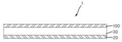
도 1은 본 발명의 일 실시예에 따른 액정표시장치용 모듈의 개략적인 단면도이다.
도 2는 도 1의 제2편광판의 단면도이다.
도 3은 도 2의 광학필름의 분해 사시도이다.
도 4는 본 발명의 다른 실시예에 따른 액정표시장치용 모듈 중 제2편광판의 단면도이다.
도 5는 본 발명의 또 다른 실시예에 따른 액정표시장치용 모듈 중 제2편광판의 단면도이다.
도 6은 본 발명의 또 다른 실시예에 따른 액정표시장치용 모듈 중 제2편광판의 단면도이다.
도 7은 본 발명의 또 다른 실시예에 따른 액정표시장치용 모듈 중 제2편광판의 단면도이다.
도 8은 본 발명의 또 다른 실시예에 따른 액정표시장치용 모듈 중 제2편광판의 단면도이다.
도 9는 본 발명의 또 다른 실시예에 따른 액정표시장치용 모듈 중 제2편광판의 단면도이다.
도 10은 본 발명의 또 다른 실시예에 따른 액정표시장치용 모듈 중 복합광학시트의 사시도이다.
도 11은 본 발명의 일 실시예에 따른 액정표시장치의 사시도이다.
도 12는 출사각의 개념도이다.
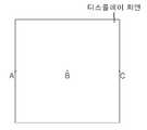
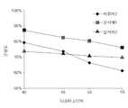
도 13은 휘도 균일도 측정시 표시장치 화면의 모식도이다.
도 14는 휘도 균일도의 측정 그래프이다.1 is a schematic cross-sectional view of a module for a liquid crystal display device according to an embodiment of the present invention.
2 is a cross-sectional view of the second polarizer plate of Fig.
3 is an exploded perspective view of the optical film of Fig.
4 is a cross-sectional view of a second polarizer of a module for a liquid crystal display according to another embodiment of the present invention.
5 is a cross-sectional view of a second polarizer of a module for a liquid crystal display according to another embodiment of the present invention.
6 is a cross-sectional view of a second polarizer of a module for a liquid crystal display according to another embodiment of the present invention.
7 is a cross-sectional view of a second polarizer of a module for a liquid crystal display according to another embodiment of the present invention.
8 is a cross-sectional view of a second polarizer of a module for a liquid crystal display according to another embodiment of the present invention.
9 is a cross-sectional view of a second polarizer of a module for a liquid crystal display according to another embodiment of the present invention.
10 is a perspective view of a composite optical sheet of a module for a liquid crystal display according to another embodiment of the present invention.
11 is a perspective view of a liquid crystal display device according to an embodiment of the present invention.
12 is a conceptual diagram of an exit angle.
13 is a schematic diagram of a display device screen when measuring luminance uniformity.
Fig. 14 is a graph showing a measurement of luminance uniformity.
첨부한 도면을 참고하여 실시예에 대하여 본 발명이 속하는 기술 분야에서 통상의 지식을 가진 자가 용이하게 실시할 수 있도록 상세히 설명한다. 본 발명은 여러 가지 상이한 형태로 구현될 수 있으며 여기에서 설명하는 실시예에 한정되지 않는다. 도면에서 본 발명을 명확하게 설명하기 위해서 설명과 관계없는 부분은 생략하였으며, 명세서 전체를 통하여 동일 또는 유사한 구성 요소에 대해서는 동일한 도면 부호를 붙였다.The present invention is not limited to the above embodiments and various changes and modifications may be made by those skilled in the art without departing from the scope of the present invention. The present invention may be embodied in many different forms and is not limited to the embodiments described herein. In order to clearly illustrate the present invention, parts not related to the description are omitted, and the same or similar components are denoted by the same reference numerals throughout the specification.
첨부한 도면을 참고하여 실시예에 대하여 본 발명이 속하는 기술 분야에서 통상의 지식을 가진 자가 용이하게 실시할 수 있도록 상세히 설명한다. 본 발명은 여러 가지 상이한 형태로 구현될 수 있으며 여기에서 설명하는 실시예에 한정되지 않는다. 도면에서 본 발명을 명확하게 설명하기 위해서 설명과 관계없는 부분은 생략하였으며, 명세서 전체를 통하여 동일 또는 유사한 구성 요소에 대해서는 동일한 도면 부호를 붙였다.The present invention is not limited to the above embodiments and various changes and modifications may be made by those skilled in the art without departing from the scope of the present invention. The present invention may be embodied in many different forms and is not limited to the embodiments described herein. In order to clearly illustrate the present invention, parts not related to the description are omitted, and the same or similar components are denoted by the same reference numerals throughout the specification.
본 명세서에서 "상부"와 "하부"는 도면을 기준으로 정의한 것으로서, 시 관점에 따라 "상부"가 "하부"로 "하부"가 "상부"로 변경될 수 있고, "위(on)" 또는 "상(on)"으로 지칭되는 것은 바로 위뿐만 아니라 중간에 다른 구조를 개재한 경우도 포함할 수 있다. 반면, "직접 위(directly on)" 또는 "바로 위"로 지칭되는 것은 중간에 다른 구조를 개지하지 않은 것을 의미한다.The terms "upper" and "lower" in this specification are defined with reference to the drawings, wherein "upper" may be changed to "lower", "lower" What is referred to as "on" may include not only superposition, but also intervening other structures in the middle. On the other hand, what is referred to as "directly on" or "directly above"
본 명세서에서 "수평 방향", "수직 방향"은 각각 직사각형의 액정표시장치 화면의 장방향과 단방향을 의미한다.In the present specification, the terms "horizontal direction" and "vertical direction" mean the longitudinal direction and the unidirectional direction of the rectangular liquid crystal display screen, respectively.
본 명세서에서 "측면"은 수평 방향을 기준으로, 구면 좌표계(spherical coordinate system)에 의한 (φ, θ)로 정면을 (0°,0°), 좌측 끝 지점을 (180°,90°), 우측 끝 지점을 (0°,90°)라고 할 때, θ 가 60° 내지 90°가 되는 영역을 의미한다.In the present specification, the term "side surface " refers to the front surface (0 DEG, 0 DEG), the left end point (180 DEG, 90 DEG) And the right end point is defined as (0 deg., 90 deg.).
본 명세서에서 "출사각"은 광원, 도광판, 액정표시장치용 모듈이 조립된 액정표시장치에서 휘도를 측정시, 도 12를 참조하면, 수평 방향을 기준으로 액정표시장치의 정면을 0°, 좌측을 -방향, 우측을 +방향, 좌측 끝 지점을 -90°, 우측 끝 지점을 +90°라고 하고, -90° 내지 +90° 각각에서 휘도를 측정하고, 측정된 휘도를 정규화(normalization)시켰을 때, 정면에서 측정된 휘도의 1/2이 되는 지점의 각도를 의미한다. 도 12에서 *로 표시된 것이 출사각이다.12, when the luminance is measured in a liquid crystal display device incorporating a light source, a light guide plate, and a module for a liquid crystal display device, the front angle of the liquid crystal display device is 0 degrees, The left end point is -90 °, the right end point is + 90 °, and the luminance is measured at each of -90 ° to + 90 °, and the measured luminance is normalized Means the angle of the point at which the luminance measured at the front is half of the luminance. In Fig. 12, the emission angle is indicated by *.
본 명세서에서 "종횡비(aspect ratio)"는 광학구조물의 최대 폭에 대한 최대 높이의 비(최대 높이/최대 폭)를 의미한다.As used herein, the term "aspect ratio" means the ratio of the maximum height to the maximum width of the optical structure (maximum height / maximum width).
본 명세서에서 "주기"는 광학필름 중 하나의 음각 패턴의 폭과 하나의 평탄부의 폭의 합을 의미한다.As used herein, the term "period" means the sum of the width of the engraved pattern of one of the optical films and the width of one flat portion.
본 명세서에서 "면방향 위상차(Re)"는 하기 식 A로 표시되고, "두께 방향 위상차(Rth)"는 하기 식 B로 표시된다:In the present specification, "retardation in the retardation direction (Re)" is expressed by the following formula A and "retardation in thickness direction (Rth)
<식 A><Formula A>
Re = (nx - ny) x dRe = (nx - ny) xd
<식 B><Formula B>
Rth = ((nx + ny)/2 - nz) x dRth = ((nx + ny) / 2 - nz) xd
(상기 식 A, B에서, nx, ny 및 nz는 파장 550nm에서 각각 해당 광학소자의 지상축 방향, 진상축 방향 및 두께 방향의 굴절률이고, d는 해당 광학소자의 두께(단위:nm)이다).(Where nx, ny and nz are refractive indexes in the slow axis direction, the fast axis direction and the thickness direction of the optical element at a wavelength of 550 nm, and d is the thickness (unit: nm) of the optical element) .
본 명세서에서 "휘도 균일도"는 도 13을 참조하면, 광원, 도광판, 액정표시장치용 모듈이 조립된 액정표시장치에서, 디스플레이 화면의 중앙 지점을 B, 좌측 끝지점 A, 우측 끝지점 C라고 하고, A,B,C 지점에서 각각의 휘도를 측정하고, 이 중 최대 휘도값(휘도max)과 최소 휘도값(휘도min)을 구한다. 휘도 균일도는 {(휘도min)/(휘도max)} x 100으로 계산된 값이다. 휘도는 측정 장치 EZCONTRAST X88RC(EZXL-176R-F422A4, ELDIM사)를 B지점에 고정하고, 상기 측정 장치의 방향을 각각 A,B,C지점으로 틀어서 측정한 값이다. 도 13에서 A, B, C는 동일 선상에 있다.Referring to FIG. 13, in the present invention, a central point of a display screen is referred to as B, a left end point A, and a right end point C in a liquid crystal display device in which a light source, a light guide plate, and a module for a liquid crystal display device are assembled , A, B, and C, and the maximum luminance value (luminance max) and the minimum luminance value (luminance min) are obtained. The luminance uniformity is a value calculated as {(luminance min) / (luminance max)} x 100. The luminance was a value obtained by fixing the measuring device EZCONTRAST X88RC (EZXL-176R-F422A4, ELDIM Co.) to the point B and changing the direction of the measuring device to the points A, B and C, respectively. 13, A, B, and C are on the same line.
본 명세서에서 "(메트)아크릴"은 아크릴 및/또는 메타아크릴을 의미한다.As used herein, "(meth) acrylic" means acrylic and / or methacrylic.
본 명세서에서 "정상부(top part)"는 구조물 중 최하부를 기산으로 하였을 때 최상부에 있는 부분을 의미한다.As used herein, the term "top part " refers to the uppermost part of the structure when the lowest part of the structure is assumed to be the basis.
이하, 본 발명의 일 실시예에 따른 액정표시장치용 모듈을 도 1 내지 도 3을 참고하여 설명한다. 도 1은 본 실시예에 따른 액정표시장치용 모듈의 개략적인 단면도, 도 2는 도 1의 제2편광판의 단면도, 도 3은 도 2의 광학필름의 분해 사시도이다.Hereinafter, a module for a liquid crystal display device according to an embodiment of the present invention will be described with reference to FIGS. 1 to 3. FIG. Fig. 1 is a schematic cross-sectional view of a module for a liquid crystal display device according to the present embodiment, Fig. 2 is a cross-sectional view of the second polarizing plate of Fig. 1, and Fig. 3 is an exploded perspective view of the optical film of Fig.
도 1을 참고하면, 본 실시예에 따른 액정표시장치용 모듈(1)은 제1편광판(20), 액정패널(30) 및 제2편광판(100)을 포함할 수 있다.1, the
제1편광판(20)은 액정패널(30)의 하부에 형성되는 것으로, 입사된 광을 편광시킬 수 있다. 제1편광판(20)은 제1편광자 및 제1보호층을 포함할 수 있다.The first
제1편광자는 입사된 광을 편광시키는 것으로, 당업자에게 통상적으로 알려진 편광자, 예를 들면 폴리비닐알콜계 필름이 1축 연신된 폴리비닐알콜계 편광자, 또는 폴리비닐알콜계 필름을 탈수시킨 폴리엔계 편광자를 포함할 수 있다.The first polarizer is used to polarize the incident light. The first polarizer may be a polarizer conventionally known to those skilled in the art, for example, a polyvinyl alcohol polarizer in which a polyvinyl alcohol film is uniaxially stretched or a polyene polarizer in which a polyvinyl alcohol film is dehydrated . ≪ / RTI >
제1보호층은 제1편광자 상에 형성되어, 제1편광자를 보호할 수 있다. 제1보호층은 등방성 광학필름일 수 있다. 상기 "등방성 광학필름"은 nx, ny, nz가 실질적으로 동일한 필름을 의미하며, 상기 "실질적으로 동일한"은 완전히 동일한 경우뿐만 아니라 약간의 오차를 포함하는 경우를 모두 포함한다. 구체적으로, 제1보호층은 파장 550nm에서 Re가 5nm 이하, 구체적으로 0.1nm 내지 5nm가 될 수 있다. 제1보호층은 파장 550nm에서 Rth가 5nm 이하, 구체적으로 0.1nm 내지 5nm가 될 수 있다. 상기 Re, Rth 범위에서, 액정 패널에 대해 법선 방향과 경사 방향에서의 명암비를 증가시킬 수 있다.A first protective layer may be formed on the first polarizer to protect the first polarizer. The first protective layer may be an isotropic optical film. The "isotropic optical film" means a film in which nx, ny, and nz are substantially the same, and the "substantially the same" includes not only completely identical cases but also cases including some errors. Specifically, the first protective layer may have a Re of 5 nm or less, specifically 0.1 nm to 5 nm at a wavelength of 550 nm. The first protective layer may have a Rth of 5 nm or less, specifically 0.1 nm to 5 nm at a wavelength of 550 nm. The contrast ratio in the normal direction and the oblique direction with respect to the liquid crystal panel can be increased in the Re and Rth ranges.
도 1에서 도시되지 않았지만, 제1편광판(20)은 점착층 또는 접착층에 의해 액정패널(30)에 점착될 수 있다. 점착층 또는 접착층은 점착성 수지, 및 선택적으로 가교제, 실란커플링제, 광라디칼 개시제, 또는 광양이온 개시제를 포함하는 조성물로 형성될 수 있다. 점착층 또는 접착층은 광확산제를 더 포함함으로써 광 확산 효과를 높일 수도 있다. 광확산제는 당업자에게 알려진 통상의 광확산제를 포함할 수 있다.Although not shown in Fig. 1, the first
액정패널(30)은 제1편광판(20)과 제2편광판(100) 사이에 형성되어, 제1편광판(20)으로부터 입사된 광을 제2편광판(100)으로 투과시킬 수 있다. 액정패널(30)은 제1기판, 제2기판 및 제1기판과 제2기판 사이에 고정되는 표시 매체인 액정층을 포함한다. 제1기판은 컬러필터 및 블랙매트릭스가 장착되어 있다. 제2기판은 액정의 전기광학특성을 제어하기 위한 스위칭 소자, 소스 신호를 제공하기 위해 스위칭 소자와 신호선에 게이트 신호를 제공하기 위한 주사선, 화소 전극, 카운터 전극을 포함한다. 액정층은 전계를 미인가시에는 균일하게 배향된 액정을 포함할 수 있다. 구체적으로, 액정패널(30)은 VA(vertical alignment) 모드, PVA(patterned vertical alignment) 모드 또는 S-PVA(super-patterned vertical alignment) 모드를 채용할 수 있다.The
제2편광판(100)은 액정패널(30)의 상부에 형성되는 것으로, 액정패널(30)로부터 입사된 집광을 편광시키고 확산시킬 수 있다. 그 결과, 제2편광판(100)은 측면에서의 명암비와 휘도 균일도를 높이고, 측면에서의 시야각을 개선하며, 액정표시장치의 화면 크기에 따른 휘도 균일도의 차이를 최소화할 수 있다. 제2 편광판(100)은 제2편광자, 광학필름, 및 제2보호층을 포함할 수 있다.The second
이하, 도 2를 참조하여 본 실시예에 따른 제2편광판(100)을 설명한다. 도 2를 참조하면, 본 실시예에 따른 제2편광판(100)은 제2편광자(110), 광학필름(120), 및 제2보호층(130)을 포함할 수 있다.Hereinafter, the second
제2편광자(110)는 액정패널(30) 상에 형성되는 것으로, 액정패널(30)로부터 입사된 집광을 편광시킬 수 있다. 제2편광자(100)는 제1편광자와 동일 또는 이종의 편광자를 포함할 수 있다.The
광학필름(120)은 제2편광자(110) 상에 형성되며 제2보호층(130)의 바로 위에 형성되는 것으로, 제2편광자(110)로부터 입사된 편광을 확산시켜 줄 수 있다. 이 때, 광학필름(120)은 제2 보호층(130)에 직접적으로 접하여 형성될 수 있다. 그 결과, 측면에서의 명암비와 휘도 균일도를 높이고, 측면에서의 시야각을 개선하며, 액정표시장치의 화면 크기에 따른 휘도 균일도의 차이를 최소화할 수 있다.The
광학필름(120)은 저굴절률 패턴층(121)과 고굴절률 패턴층(122)을 포함할 수 있다. 광학필름(120)은 액정패널(30)로부터 출사된 광이 저굴절률 패턴층(121)으로 입사되어 고굴절률 패턴층(122)으로 출사되도록 액정표시장치용 모듈(1)에 배치될 수 있다. 그 결과, 광의 확산 효과를 높여 측면 명암비와 시야각 개선 효과가 클 수 있다.The
이하, 본 실시예에 따른 광학필름(120)을 도 2와 도 3을 참조하여 상세히 설명한다. 도 2 및 도3을 참조하면, 본 실시예에 따른 광학필름(120)은 하나 이상의 음각 패턴(127)이 형성된 고굴절률 패턴층(122) 및 음각 패턴(127)의 적어도 일부를 충진하는 충진 패턴(125)을 포함하는 저굴절률 패턴층(121)을 포함할 수 있다.Hereinafter, the
고굴절률 패턴층(122)에는 제1면(124)이 형성되어 있고, 제1면(124)에는 하나 이상의 음각 패턴(127)과 평탄부(126)가 형성되어 있을 수 있다. 도 2 및 도 3은 하나의 음각 패턴(127)과 하나의 평탄부(126)가 교대로 형성된 광학필름을 도시한 것이나, 음각 패턴(127)과 평탄부(126)의 각각의 형성 순서는 특별히 제한되지 않는다. 도 2 및 도 3은 음각 패턴(127)이 곡면을 포함하는 렌티큘러 렌즈 패턴인 경우를 예시하나 본 발명에 이에 제한되는 것은 아니다. 곡면이 렌즈 역할을 하여 제2편광자(110)로부터 입사된 광을 도달 위치에 따라 다양한 방향으로 굴절시킴으로써 확산시킬 수 있다. 곡면은 구면, 포물면, 타원면, 쌍곡면 또는 무정형의 곡면이 될 수도 있다. 음각 패턴(127)은 정상부에 곡면이 형성되고 단면이 3각형 내지 10각형인 프리즘 패턴도 될 수 있다. 또한, 도 2 및 도 3은 곡면이 요철이 없는 경우를 나타낸 것이나, 곡면에는 요철이 더 형성되어 확산 효과를 더 높일 수도 있다. 음각 패턴(127)은 종횡비(H3/P3)가 1.0 이하, 구체적으로 0.4 내지 1.0, 더 구체적으로 0.7 내지 1.0이 될 수 있다. 도 2를 참조하면, 종횡비는 음각 패턴의 최대 폭에 대한 음각 패턴의 최대 높이의 비이다. 고굴절률 패턴층(122)의 전체 폭(A)에 대한 음각 패턴(127)의 폭 전체의 합(B)의 비율(B/A)은 40% 내지 60%, 구체적으로 45% 내지 55%가 될 수 있다. 상기 종횡비 및 비율 범위에서, 측면에서의 명암비와 휘도 균일도를 높이고, 측면에서의 시야각을 개선하며, 액정표시장치의 화면 크기에 따른 휘도 균일도의 차이를 최소화할 수 있다.A
다시 도 2를 참조하면, 음각 패턴(127)의 폭(P3)은 30㎛ 이하, 구체적으로 5㎛ 내지 20㎛가 될 수 있다. 음각 패턴(127)의 최대 높이(H3)는 20㎛ 이하, 구체적으로 15㎛ 이하, 더 구체적으로 5㎛ 내지 15㎛, 더 구체적으로 5㎛ 내지 10㎛가 될 수 있다. 상기 범위에서, 확산 효과가 있을 수 있다.Referring again to FIG. 2, the width P3 of the
평탄부(126)는 음각 패턴(127)과 음각 패턴(127) 사이에 형성되어, 평탄부(126)에 도달한 광이 음각 패턴(127)에서 전반사되어 출사됨으로써 집광을 확산시킬 수 있다. 평탄부(126)의 폭(P4)은 음각 패턴(127)의 최대 폭(P3)과 같거나 클 수 있다(P4≥P3). 평탄부(126)의 폭(P4)에 대한 음각 패턴(127)의 최대 폭(P3)의 비율(P3/P4)은 1 이하일 수 있다. 주기(C)에 대한 음각 패턴(127)의 최대 폭(P3)의 비(P3/C)는 0.5 이하일 수 있다. 상기 범위에서, 집광 및 확산 효과가 클 수 있다. 저굴절률 패턴층(121)에 도달한 광은 평탄부(126)에 의해 충진 패턴(125)으로 반사되지 않는 광도 확산시킴으로써 집광의 확산 효과를 크게 할 수 있을 뿐만 아니라 음각 패턴(127)은 소정의 주기(C)로 배치됨으로써 집광을 확산시키는 효과가 클 수 있다.The
고굴절률 패턴층(122)은 굴절률이 1.0이상, 구체적으로1.50 이상, 보다 구체적으로 1.50 내지 1.60이 될 수 있다. 상기 범위에서, 광 확산 효과가 우수하다. 고굴절률 패턴층(122)은 (메트)아크릴계, 폴리카보네이트계, 실리콘계, 에폭시계 수지 중 하나 이상을 포함하는 자외선 경화형 조성물로 형성될 수 있지만, 이에 제한되지 않는다.The high refractive
저굴절률 패턴층(121)은 제2편광자(110) 상에 형성되어, 제2편광자(110)로부터 일 방향으로 입사된 편광을 입사 위치에 따라 다양한 방향으로 굴절시켜 출사시킴으로써 광을 확산시킬 수 있다.The low refractive
저굴절률 패턴층(121)은 고굴절률 패턴층(122)보다 굴절률이 낮은 물질로 형성될 수 있고, 굴절률이 1.50 미만, 구체적으로 1.35 이상 1.50 미만이 될 수 있다. 상기 범위에서, 광 확산 효과가 크고, 제조가 용이할 수 있다. 저굴절률 패턴층(121)은 자외선 경화성인 투명 수지를 포함하는 조성물로 형성될 수 있다. 구체적으로, 수지는 (메트)아크릴계, 폴리카보네이트계, 실리콘계, 에폭시계 수지 중 하나 이상을 포함할 수 있지만, 이에 제한되지 않는다. 조성물은 패턴층 형성을 위해 통상의 개시제를 더 포함할 수도 있다. 저굴절률 패턴층(121)은 고굴절률 패턴층(122)의 제1면(124)과 마주보는 제2면(123)을 포함하고, 하나 이상의 충진 패턴(125)을 포함할 수 있다. 충진 패턴(125)은 고굴절률 패턴층(122)의 음각 패턴(127)의 적어도 일부를 충진할 수 있다. 상기 "적어도 일부를 충진"은 음각 패턴(127)을 완전히 충진하거나 부분적으로 충진하는 경우를 모두 포함한다. 충진 패턴이 음각 패턴을 부분적으로 충진하는 경우, 잔여 부분은 공기 또는 소정의 굴절률을 갖는 수지로 충진될 수 있다. 구체적으로, 상기 수지는 저굴절률 패턴층 대비 동일하거나 크고 고굴절률 패턴층 대비 동일하거나 작은 굴절률을 가질 수 있다. 도 3은 충진 패턴(125)과 음각 패턴(127)이 스트라이프 형의 연장된 형태로 형성된 광학필름을 도시한 것이나, 충진 패턴(125)과 음각 패턴(127)은 도트 형태로 형성될 수도 있다. 상기 "도트"는 돌출부와 음각 패턴의 조합이 분산되어 있는 것을 의미한다.The low refractive
고굴절률 패턴층(122)과 저굴절률 패턴층(121)의 굴절률 차이는 0.20 이하, 구체적으로 0.10 내지 0.20, 더 구체적으로 0.10 내지 0.18이 될 수 있다. 상기 범위에서, 집광 및 확산 효과가 있을 수 있다.The refractive index difference between the high refractive
도 2 및 도 3에서 도시되지 않았지만, 고굴절률 패턴층, 저굴절률 패턴층 중 하나 이상은 광확산제를 포함할 수 있다. 그 결과, 표시장치 화면의 수평 방향인 좌우 방향의 시야각과 수직 방향인 상하 방향의 시야각이 동시에 개선될 수 있다. 또한, 광확산제를 포함하지 않는 고굴절률 패턴층 대비 음각 패턴의 높이를 더 낮추어도 시야각 개선 효과가 클 수 있다. 광확산제는 유기계 광확산제, 무기계 광확산제, 또는 이들의 혼합물을 사용할 수 있다. 유기계 광확산제와 무기계 광확산제의 혼합물은 저굴절률 패턴층 또는 고굴절률 패턴층의 확산성과 투과성을 좋게 할 수 있다. 광확산제는 단독 또는 2종 이상 혼합하여 포함될 수 있다. 유기계 광확산제는 (메트)아크릴계 입자, 실록산계 입자, 스티렌계 입자 중 하나 이상을 포함할 수 있다. 무기계 광확산제는 탄산칼슘, 황산바륨, 이산화티탄, 수산화알루미늄, 실리카, 유리, 활석, 운모, 화이트카본, 산화마그네슘, 산화 아연 중 하나 이상을 포함할 수 있다. 특히, 무기계 광확산제는 유기계 광확산제만 포함하는 경우 대비 백색도 저하를 방지하고 광확산성을 증가시킬 수 있다. 광확산제(128)는 형태, 입경에 제한을 두지 않는다. 구체적으로, 광확산제는 구상의 가교된 입자를 포함할 수 있고, 평균 입경은 0.1㎛ 내지 30㎛, 구체적으로 0.5㎛ 내지 10㎛, 더 구체적으로 1㎛ 내지 5㎛가 될 수 있다. 상기 범위에서, 광확산 효과를 구현할 수 있고, 패턴층의 표면 거칠기가 증가하여 제2보호층과의 접착력이 문제되지 않고, 분산도가 좋을 수 있다. 광확산제는 고굴절률 패턴층, 저굴절률 패턴층 단독 또는 고굴절률 패턴층과 저굴절률 패턴층 전체에 대해 0.1중량% 내지 20중량%, 구체적으로 1중량% 내지 15중량%로 포함될 수 있다. 상기 범위에서, 광확산 효과가 있을 수 있다. 저굴절률 패턴층에 광확산제를 사용하는 경우 수지의 굴절률 선택의 폭이 확대되고 용절감 효과가 있다.Although not shown in Figs. 2 and 3, at least one of the high refractive index pattern layer and the low refractive index pattern layer may include a light diffusing agent. As a result, the horizontal viewing angle in the horizontal direction of the display device screen and the vertical viewing angle in the vertical direction can be improved at the same time. Further, even if the height of the engraved pattern is lower than that of the high refractive index pattern layer not containing the light diffusing agent, the effect of improving the viewing angle may be large. As the light diffusing agent, an organic light diffusing agent, an inorganic light diffusing agent, or a mixture thereof may be used. The mixture of the organic light-diffusing agent and the inorganic light-diffusing agent can improve the diffusibility and transmittance of the low-refractive-index pattern layer or the high-refractive-index pattern layer. The light diffusing agents may be included singly or in combination of two or more. The organic light-diffusing agent may include at least one of (meth) acrylic-based particles, siloxane-based particles, and styrene-based particles. The inorganic light-diffusing agent may include at least one of calcium carbonate, barium sulfate, titanium dioxide, aluminum hydroxide, silica, glass, talc, mica, white carbon, magnesium oxide and zinc oxide. In particular, when the inorganic light diffusing agent contains only the organic light diffusing agent, the decrease in contrast whiteness can be prevented and the light diffusing property can be increased. The light diffusing agent 128 is not limited in shape and particle size. Specifically, the light-diffusing agent may include spherical cross-linked particles, and the average particle diameter may be 0.1 탆 to 30 탆, specifically 0.5 탆 to 10 탆, more specifically 1 탆 to 5 탆. Within this range, the light diffusion effect can be realized, the surface roughness of the pattern layer is increased, and the adhesion with the second protective layer is not a problem, and the degree of dispersion can be good. The light diffusing agent may be contained in the high refractive index pattern layer, the low refractive index pattern layer alone, or the high refractive index pattern layer and the low refractive index pattern layer in an amount of 0.1 wt% to 20 wt%, specifically 1 wt% to 15 wt%. Within this range, there may be a light diffusion effect. When a light diffusing agent is used for the low refractive index pattern layer, the range of the refractive index selection of the resin is increased and the use of the resin is saved.
이하, 제2보호층(130)에 대해 설명한다. 제2 보호층(130)은 고굴절률 패턴층(122) 또는 저굴절률 패턴층(121) 상에 형성되어 광학필름(120)을 보호하고, 광학필름(120)을 지지할 수 있다. 도 2는 제2보호층(130)이 고굴절률 패턴층(122)의 바로 위에 형성된 경우를 예시하나, 본 발명이 이에 제한되는 것은 아니며, 제2 보호층(130)은 저굴절률 패턴층(121) 상에 형성될 수 있다. 즉, 도 2는 저굴절률 패턴층(121), 고굴절률 패턴층(122) 및 제2 보호층(130)의 순서로 순차적으로 적층된 구조를 나타내는 것이다. 그러나, 제2 보호층(130), 저굴절률 패턴층(121) 및 고굴절률 패턴층(122)의 순서로 순차적으로 적층된 구조를 가질 수도 있고, 이 경우 제2 보호층(130)은 하부의 제2 편광자(110)와 접착층으로 일체화될 수 있다.Hereinafter, the second
제2보호층(130)은 Re가 10,000nm 이상, 구체적으로 10,000nm 초과, 더 구체적으로 10,100nm 내지 15,000nm가 될 수 있다. 상기 범위에서, 무지개 얼룩이 시인되지 않게 할 수 있다. 제2 보호층(130)은 광학적 투명 수지를 1축 또는 2축 연신한 필름일 수 있다. 구체적으로, 수지는 폴리에틸렌테레프탈레이트(PET), 폴리부틸렌테레프탈레이트, 폴리에틸렌나프탈레이트, 폴리부틸렌나프탈레이트 등을 포함하는 폴리에스테르, 아크릴, 시클릭올레핀폴리머(COP), 트리아세틸셀룰로스(TAC) 등을 포함하는 셀룰로스 에스테르, 폴리비닐아세테이트, 폴리비닐클로라이드(PVC), 폴리노르보르넨, 폴리카보네이트(PC), 폴리아미드, 폴리아세탈, 폴리페닐렌에테르, 폴리페닐렌술피드, 폴리술폰, 폴리에테르술폰, 폴리아릴레이트, 폴리이미드 중 하나 이상을 포함할 수 있다. 제2보호층은 상술한 수지의 변성 후 제조된 필름을 포함할 수도 있다. 상기 변성은 공중합, 브랜칭, 가교 결합, 또는 분자 말단의 변성 등을 포함할 수 있다. 제2보호층(130)과 광학필름(120)은 일체화될 수 있다. 상기 ?衢셜?는 제2보호층(130)과 광학필름(120)이 서로 독립적으로 분리되지 않은 상태를 의미한다.The second
도 2에서 도시되지 않았지만, 제2편광자(110)와 광학필름(120) 사이에는 접착층이 형성될 수 있다. 일 구체예에서, 접착층은 에폭시 수지, (메트)아크릴계 단량체, 광개시제 등을 포함하는 광경화형 접착제, 또는 폴리비닐알콜계의 수계 접착제로 형성될 수 있다. 접착층은 확산제를 더 포함함으로써 광 확산 효과를 높일 수도 있다.Although not shown in FIG. 2, an adhesive layer may be formed between the
또한, 도 2에서 도시되지 않았지만, 제2보호층(130) 상에 기능층이 더 형성될 수 있다. 기능층은 제2보호층(130)에 반사방지(anti-reflection), 저반사(low reflection), 하드코팅(hard coating), 눈부심 방지(anti-glare), 내지문성(anti-finger), 방오(anti-contamination), 확산, 굴절 기능 중 하나 이상을 제공할 수 있다. 일 구체예에서, 기능층은 제2보호층(130) 상에 독립적인 별개의 층으로 형성될 수 있다. 예를 들어, 기능층은 제2보호층(130) 상에 기능층 형성용 조성물을 도포하여 형성하거나 접착층 또는 점착층을 통해 제2 보호층(130) 상에 적층될 수 있다. 다른 구체예에서, 기능층은 제2보호층(130)의 일면이 기능층이 되도록 형성될 수도 있다.Further, although not shown in FIG. 2, a functional layer may be further formed on the second
또한, 도 2에서 도시되지 않았지만, 제2 보호층(130), 저굴절률 패턴층(121) 및 고굴절률 패턴층(122)의 순서로 순차적으로 적층된 구조를 가질 경우, 기능층은 고굴절률 패턴층(122) 상에 독립적인 별개의 층으로 형성될 수 있다. 또한, 도 4를 참조하면, 제2편광판(100')은 일 표면이 상기와 같은 기능을 갖도록 표면처리하여 형성된 고굴절률 패턴층(122')을 포함하는 광학필름(120')을 포함할 수 있다. 예를 들어, 고굴절률 패턴층(122')은 일 표면이 요철을 갖도록 형성되거나 미립자 등을 사용하여 고굴절률 패턴층(122')의 일면이 기능층이 되도록 형성할 수 있다.Although not shown in FIG. 2, when the second
이하, 본 실시예에 따른 제2편광판의 제조 방법에 대해 설명한다.Hereinafter, a method of manufacturing the second polarizing plate according to this embodiment will be described.
우선, 제2보호층과 광학필름의 적층체를 제조한다. 구체적으로, 제2보호층의 일면에 고굴절률 패턴층용 수지를 코팅한다. 코팅 방법은 특별히 제한되지 않는다. 예를 들면, 바코팅, 스핀코팅, 딥코팅, 롤코팅, 플로우코팅, 다이코팅 등이 될 수 있다. 그런 다음, 코팅층 위에 양각의 충진 패턴과 평탄부가 형성된 패턴 필름을 이용하여 패턴을 전사한다. 그런 다음, 저굴절률 패턴층용 수지를 전사된 패턴 내에 충진 및 코팅하고 경화시킨다. 경화는 광경화, 열경화 중 하나 이상을 포함할 수 있다. 광경화는 파장 400nm 이하에서 10 mJ/cm2 내지 1000mJ/cm2의 광량으로 조사하는 것을 포함할 수 있다. 열경화는 40℃ 내지 200℃에서 1시간 내지 30시간 동안 처리하는 것을 포함할 수 있다. 상기 범위에서 패턴층용 수지가 충분히 경화될 수 있다.First, a laminate of the second protective layer and the optical film is produced. Specifically, a resin for a high refractive index pattern layer is coated on one surface of the second protective layer. The coating method is not particularly limited. For example, bar coating, spin coating, dip coating, roll coating, flow coating, die coating, and the like. Then, the pattern is transferred using a pattern film on which a filling pattern and a flat portion are formed on the coating layer. Then, the resin for the low refractive index pattern layer is filled and coated in the transferred pattern and cured. The curing may include one or more of light curing, heat curing. Photocuring may involve irradiation with light amount of 10 mJ / cm2 to 1000mJ / cm2 at a wavelength of 400nm or less. Thermal curing may include treating at 40 占 폚 to 200 占 폚 for 1 hour to 30 hours. Within this range, the resin for the pattern layer can be sufficiently cured.
제2편광자를 제조한다. 제2편광자는 통상의 방법으로 제조될 수 있다. 일 구체예에서, 제2편광자는 폴리비닐알콜계 수지 필름을 팽윤, 연신, 염착시켜 제조할 수 있다. 팽윤, 연신, 염착은 당업자에게 알려진 통상의 방법으로 수행될 수 있다. 다른 구체예에서, 제2편광자는 폴리비닐알콜계 수지 필름을 탈수시켜 제조될 수 있다.Thereby producing a second polarizer. The second polarizer may be manufactured by a conventional method. In one embodiment, the second polarizer can be produced by swelling, stretching, and dyeing a polyvinyl alcohol-based resin film. Swelling, stretching, and dyeing may be performed by conventional methods known to those skilled in the art. In another embodiment, the second polarizer may be prepared by dewatering a polyvinyl alcohol-based resin film.
상기 적층체 중 광학필름의 일면에 편광판용 접착제를 코팅하고 제2편광자와 합지한 다음 경화시켜 제2편광판을 제조한다.An adhesive for a polarizing plate is coated on one side of the optical film in the laminate, and the second polarizer is prepared by laminating with a second polarizer and then curing.
이하, 본 발명의 다른 실시예에 따른 액정표시장치용 모듈을 도 5를 참고하여 설명한다. 도 5는 본 실시예에 따른 제2편광판의 단면도이다.Hereinafter, a liquid crystal display module according to another embodiment of the present invention will be described with reference to FIG. 5 is a cross-sectional view of a second polarizing plate according to this embodiment.
본 실시예에 따른 액정표시장치용 모듈은 제1편광판, 액정패널 및 제2편광판을 포함할 수 있다. 도 2의 제2편광판 대신에 도 5의 제2편광판을 포함하는 점을 제외하고는 본 발명의 일 실시예에 따른 액정표시장치용 모듈과 실질적으로 동일하다. 이에, 이하에서는 도 5의 제2편광판에 대해서만 설명한다.The module for a liquid crystal display device according to this embodiment may include a first polarizing plate, a liquid crystal panel, and a second polarizing plate. Except that the second polarizing plate of FIG. 5 is included in place of the second polarizing plate of FIG. 2, the module is substantially the same as the module for a liquid crystal display according to an embodiment of the present invention. Hereinafter, only the second polarizing plate of Fig. 5 will be described.
도 5를 참조하면, 제2편광판(200)은 제2편광자(110), 저굴절률 패턴층(141)과 고굴절률 패턴층(142)을 포함하는 광학필름(140), 및 제2보호층(130)을 포함할 수 있다. 제2편광자(110) 및 제2보호층(130)은 상술한 본 발명의 일 실시예에 따른 액정표시장치용 모듈과 실질적으로 동일한 바, 여기서는 광학필름(140)을 중심으로 설명한다.5, the second
광학필름(140)은 제2편광자(110) 상 및 제2보호층(130)의 바로 하부에 형성되는 것으로, 제2편광자(110)로부터 입사된 편광을 확산시켜 줄 수 있다. 그 결과, 측면 명암비를 높이고, 측면의 시야각을 크게 하고, 휘도 균일도를 높일 수 있다.The
도 5를 참조하면, 본 실시예에 따른 광학필름(140)은 하나 이상의 음각 프리즘 패턴(144)이 형성된 고굴절률 패턴층(142), 및 음각 프리즘 패턴(144)의 적어도 일부를 충진하는 충진 패턴(143)을 포함하는 저굴절률 패턴층(141)을 포함할 수 있다.5, the
도 5는 단면이 삼각형인 음각 프리즘 패턴(144)을 포함하는 제2편광판을 나타낸 것이다. 그러나, 단면이 n 각형(n은 4 내지 10의 정수)인 프리즘 패턴을 포함할 수도 있다. 또한, 도 5는 평탄부가 없는 광학필름을 도시한 것이나, 음각 프리즘 패턴(144) 사이에 도 2의 평탄부(126)가 더 형성될 수도 있다. 또한, 도 5의 음각 프리즘 패턴에 요철이 더 형성됨으로써 확산 효과를 크게 할 수 있다. 또한, 도 5의 음각 프리즘 패턴의 정상부에 곡면이 형성될 수도 있다.FIG. 5 shows a second polarizer plate including a
음각 프리즘 패턴(144)은 폭(P5)이 5㎛ 내지 20㎛, 구체적으로 7㎛ 내지 15㎛가 될 수 있다. 음각 프리즘 패턴(144)은 높이(H5)가 3㎛ 내지 16㎛, 구체적으로 4㎛ 내지 16㎛가 될 수 있다. 음각 프리즘 패턴(144)은 꼭지각(γ)이 55° 내지 90°, 구체적으로 65° 내지 80°가 될 수 있다. 음각 프리즘 패턴 (144)은 종횡비가 0.50 내지 0.96, 구체적으로 0.6 내지 0.8이 될 수 있다. 상기 폭, 높이, 꼭지각 및 종횡비 범위에서, 광 확산 효과가 있을 수 있다.The
이하, 본 발명의 또 다른 실시예에 따른 액정표시장치용 모듈을 도 6을 참고하여 설명한다. 도 6은 본 실시예에 따른 액정표시장치용 모듈 중 제2편광판의 단면도이다.Hereinafter, a liquid crystal display module according to another embodiment of the present invention will be described with reference to FIG. 6 is a cross-sectional view of a second polarizer plate of the module for a liquid crystal display device according to the present embodiment.
본 발명의 또 다른 실시예에 따른 액정표시장치용 모듈은 제1편광판, 액정패널 및 제2편광판을 포함할 수 있다. 도 2의 제2편광판 대신에, 도 6의 제2편광판을 포함하는 것을 제외하고는 본 발명의 일 실시예에 따른 액정표시장치용 모듈과 실질적으로 동일하다. 이에, 이하에서는 도 6의 제2편광판에 대해서만 설명한다.The module for a liquid crystal display according to another embodiment of the present invention may include a first polarizer, a liquid crystal panel, and a second polarizer. The second polarizing plate of Fig. 2 is substantially the same as the module of the liquid crystal display according to the embodiment of the present invention, except that the second polarizing plate of Fig. 6 is included. Hereinafter, only the second polarizing plate of Fig. 6 will be described.
도 6을 참조하면, 본 실시예에 따른 제2편광판(300)은 제2편광자(110), 저굴절률 패턴층(151)과 고굴절률 패턴층(152)을 포함하는 광학필름(150), 및 제2보호층(130)을 포함할 수 있다. 고굴절률 패턴층(152)은 음각 패턴(153)과 평탄부(154)를 포함하고, 음각 패턴(153)과 평탄부(154)가 만나는 경계면에 곡면(155)이 형성될 수 있다. 그 결과, 집광의 확산 효과가 더 클 수 있다. 저굴절률 패턴층(151)은 음각 패턴(153)을 충진하는 충진 패턴(156)을 포함할 수 있다.6, the
이하, 본 발명의 또 다른 실시예에 따른 액정표시장치용 모듈을 도 7을 참고하여 설명한다. 도 7은 본 실시예에 따른 액정표시장치용 모듈 중 제2편광판의 단면도이다.Hereinafter, a liquid crystal display module according to another embodiment of the present invention will be described with reference to FIG. 7 is a cross-sectional view of the second polarizer plate of the module for a liquid crystal display device according to the present embodiment.
본 발명의 또 다른 실시예에 따른 액정표시장치용 모듈은 제1편광판, 액정패널 및 제2편광판을 포함할 수 있다. 도 2의 제2편광판 대신에, 도 7의 제2편광판을 포함하는 것을 제외하고는 본 발명의 일 실시예에 따른 액정표시장치용 모듈과 실질적으로 동일하다. 이에, 도7의 제2편광판에 대해서만 설명한다.The module for a liquid crystal display according to another embodiment of the present invention may include a first polarizer, a liquid crystal panel, and a second polarizer. The second polarizing plate of Fig. 2 is substantially the same as the module of the liquid crystal display according to the embodiment of the present invention except that the second polarizing plate of Fig. 7 is included. Only the second polarizing plate of Fig. 7 will be described.
도 7을 참조하면, 본 실시예에 따른 제2편광판(400)은 제2편광자(110), 음각 패턴(127)과 평탄부(126)가 형성된 고굴절률 패턴층(122)과 저굴절률 패턴층(161)을 포함하는 광학필름(160) 및 제2보호층(130)을 포함할 수 있다. 도 2의 제2편광판 대비 저굴절률 패턴층(161)의 두께와 음각 패턴(127)의 높이가 동일한 것을 제외하고는 실질적으로 동일하다.Referring to FIG. 7, the
이하, 본 발명의 또 다른 실시예에 따른 액정표시장치용 모듈을 도 8을 참고하여 설명한다. 도8은 본 실시예에 따른 액정표시장치용 모듈 중 제2편광판의 단면도이다.Hereinafter, a liquid crystal display module according to another embodiment of the present invention will be described with reference to FIG. 8 is a cross-sectional view of the second polarizer plate of the module for a liquid crystal display device according to the present embodiment.
본 발명의 또 다른 실시예에 따른 액정표시장치용 모듈은 제1편광판, 액정패널 및 제2편광판을 포함할 수 있다. 도 2의 제2편광판 대신에, 도 8의 제2편광판을 포함하는 것을 제외하고는 본 발명의 일 실시예에 따른 액정표시장치용 모듈과 실질적으로 동일하다. 이에, 도 8의 제2편광판에 대해서만 설명한다.The module for a liquid crystal display according to another embodiment of the present invention may include a first polarizer, a liquid crystal panel, and a second polarizer. 8 is substantially the same as the module for a liquid crystal display according to an embodiment of the present invention, except that the second polarizing plate of Fig. 8 is included instead of the second polarizing plate of Fig. Thus, only the second polarizing plate of Fig. 8 will be described.
도 8을 참조하면, 본 실시예에 따른 제2편광판(500)은 제2편광자(110), 저굴절률 패턴층(121)과 고굴절률 패턴층(122)을 포함하는 광학필름(120), 제2보호층(130) 및 제3보호층(170)을 포함할 수 있다. 도 2의 제2편광판 대비 제3보호층(170)을 더 포함하는 것을 제외하고는 실질적으로 동일하다.Referring to FIG. 8, the
제3보호층(170)은 제2편광자(110)의 하부에 형성되어, 제2편광자(110)를 보호하고, 제2보호층(130)과 함께 가혹 조건에서도 제2편광판(500)의 휨을 억제할 수 있다.The third
제3보호층(170)은 광학적 투명 수지를 1축 또는 2축 연신한 필름일 수 있다. 구체적으로, 수지는 폴리에틸렌테레프탈레이트, 폴리부틸렌테레프탈레이트, 폴리에틸렌나프탈레이트, 폴리부틸렌나프탈레이트 등을 포함하는 폴리에스테르, 아크릴, 시클릭올레핀폴리머, 트리아세틸셀룰로스 등을 포함하는 셀룰로스 에스테르, 폴리비닐아세테이트, 폴리비닐클로라이드, 폴리노르보르넨, 폴리카보네이트, 폴리아미드, 폴리아세탈, 폴리페닐렌에테르, 폴리페닐렌술피드, 폴리술폰, 폴리에테르술폰, 폴리아릴레이트, 폴리이미드 중 하나 이상을 포함할 수 있다. 제3보호층(170)은 상술한 수지의 변성 후 제조된 필름을 포함할 수도 있다. 상기 변성은 공중합, 브랜칭, 가교 결합, 또는 분자 말단의 변성 등을 포함할 수 있다. 제3보호층(170)은 소정 범위의 위상차를 가져 시야각 보상 기능을 가질 수 있다. 구체적으로, 제3보호층(170)은 파장 550nm에서 면방향 위상차(Re)가 40nm 내지 60nm가 될 수 있다. 상기 범위에서 시야각을 보상하여 화상 품질을 좋게 할 수 있다.The third
도 8은 광학필름(120)이 제2보호층(130)과 제2편광자(110) 사이에 형성된 경우를 도시한 것이나, 광학필름(120)이 제2편광자(110)와 제3보호층(170) 사이에 형성되는 경우, 즉 제3보호층(170), 저굴절률 패턴층(121), 고굴절률 패턴층(122), 제2편광자(110) 및 제2보호층(130)의 순서로 순차적으로 형성된 구조도 포함할 수 있다.8 shows a case where the
도 8에서 도시되지 않았지만, 제3보호층(170)의 하부면에는 점착층이 더 형성되어 액정패널(30)과의 점착을 용이하게 할 수 있다. 점착층은 상술한 바와 같다. 도 8에서 도시되지 않았지만, 제2편광자(110)와 제3보호층(170) 사이에는 접착층이 형성될 수 있다.Although not shown in FIG. 8, an adhesive layer may be further formed on the lower surface of the
이하, 본 발명의 또 다른 실시예에 따른 액정표시장치용 모듈을 도 9를 참고하여 설명한다. 도 9는 본 실시예에 따른 액정표시장치용 모듈 중 제2편광판의 단면도이다.Hereinafter, a liquid crystal display module according to another embodiment of the present invention will be described with reference to FIG. 9 is a cross-sectional view of a second polarizer plate of the module for a liquid crystal display device according to the present embodiment.
본 발명의 또 다른 실시예에 따른 액정표시장치용 모듈은 제1편광판, 액정패널 및 제2편광판을 포함할 수 있다. 도2의 제2편광판 대신에, 도 9의 제2편광판을 포함하는 것을 제외하고는 본 발명의 일 실시예에 따른 액정표시장치용 모듈과 실질적으로 동일하다. 이에, 도9의 제2편광판에 대해서만 설명한다.The module for a liquid crystal display according to another embodiment of the present invention may include a first polarizer, a liquid crystal panel, and a second polarizer. Except for the second polarizing plate of Fig. 9, instead of the second polarizing plate of Fig. 2, which is substantially the same as the module for a liquid crystal display according to an embodiment of the present invention. Thus, only the second polarizing plate of Fig. 9 will be described.
도 9를 참조하면, 본 실시예에 따른 제2편광판(600)은 제2편광자(110), 저굴절률 패턴층(121)과 고굴절률 패턴층(122)을 포함하는 광학필름(120), 제3보호층(170)을 포함할 수 있다. 광학필름(120)이 제2편광자(110)의 하부, 에 형성되며, 제3보호층(170) 상에 직접적으로 형성된다는 점 및 제2보호층(130)이 배제된 것을 제외하고는 도 8의 제2편광판(500)과 실질적으로 동일하다.9, the
이하, 본 발명의 또 다른 실시예에 따른 액정표시장치용 모듈을 도 10을 참고하여 설명한다. 도 10은 본 실시예에 따른 액정표시장치용 모듈 중 복합광학시트의 사시도이다.Hereinafter, a module for a liquid crystal display according to another embodiment of the present invention will be described with reference to FIG. 10 is a perspective view of a composite optical sheet of a module for a liquid crystal display device according to the present embodiment.
본 발명의 또 다른 실시예에 따른 액정표시장치용 모듈은 복합광학시트, 제1편광판, 액정패널 및 제2편광판을 포함할 수 있다. 복합광학시트가 더 포함된 점을 제외하고는 본 발명의 일 실시예에 따른 액정표시장치용 모듈과 실질적으로 동일하다. 복합광학시트는 제1편광판의 하부에 위치하여, 하부에서 입사된 광을 집광시켜 출사시킬 수 있다. 이에, 복합광학시트에 대해서만 설명한다. A module for a liquid crystal display device according to another embodiment of the present invention may include a composite optical sheet, a first polarizer, a liquid crystal panel, and a second polarizer. Is substantially the same as the module for a liquid crystal display according to an embodiment of the present invention, except that a composite optical sheet is further included. The composite optical sheet is located below the first polarizing plate and can condense and emit light incident from below. Thus, only the composite optical sheet will be described.
도 10을 참조하면, 본 실시예에 따른 복합광학시트(10)는 일면에 하나 이상의 제1프리즘 패턴(11)을 포함하는 제1광학시트(12), 및 제1광학시트(12) 상에 형성되고 일면에 하나 이상의 제2프리즘 패턴(13)을 포함하는 제2광학시트(14)를 포함할 수 있다.10, the composite
복합광학시트(10)는 출사각 -40° 내지 +40°, 구체적으로 -30° 내지 +30°, 더 구체적으로 -28° 내지 +28°로 광을 출사시킬 수 있다. 상기 범위에서, 복합광학시트의 측면에서 출사되어 액정패널을 통과하는 광이 최소화됨으로써, 입사된 광을 집광시켜 출사시켜 측면의 명암비를 높일 수 있다.The composite
제1광학시트(12)는 제2광학시트(14)의 하부에 위치할 수 있다. 제1광학시트(12)는 상부면인 광출사면과 하부면인 광입사면을 가져, 입사되는 광의 경로를 변화시켜 제2광학시트(14)로 출사시킬 수 있다. 제1광학시트(12)는 제1베이스필름(15), 제1베이스필름(15) 상에 형성된 하나 이상의 제1 프리즘 패턴(11)을 포함할 수 있다.The first
제1베이스필름(15)은 제1광학시트(12)를 지지하는 것으로, 두께는 제한되지 않지만 10㎛ 내지 500㎛, 구체적으로 25㎛ 내지 250㎛, 보다 더 구체적으로 75㎛ 내지 150㎛가 될 수 있다. 상기 범위에서, 액정표시장치에 사용될 수 있다. 제1베이스필름(15)은 열가소성 수지 또는 이를 포함하는 조성물로 형성될 수 있다. 구체적으로, 열가소성 수지는 폴리에틸렌테레프탈레이트 수지, 폴리에틸렌나프탈레이트 수지 등을 포함하는 폴리에스테르계 수지, 폴리아세탈 수지, 아크릴계 수지, 폴리카보네이트계 수지, 스티렌계 수지, 비닐계 수지, 폴리페닐렌에테르 수지, 폴리에틸렌, 폴리프로필렌 등을 포함하는 비-시클릭형 폴리올레핀 수지, 시클로올레핀계 수지, 아크릴로니트릴-부타디엔-스티렌 공중합체 수지, 폴리아크릴레이트 수지, 폴리아릴술폰 수지, 폴리에테르술폰 수지, 폴리페닐렌술피드 수지, 불소계 수지, (메트)아크릴계 수지 중 하나 이상을 포함할 수 있다.The
제1프리즘 패턴(11)은 제1광학시트(12)의 상부면에 형성되고, 하부면으로부터 입사된 광을 집광시키고 휘도를 높일 수 있다. 도 2는 단면이 삼각형인 프리즘 패턴을 예시하나 이에 제한된 것은 아니고, 제1프리즘 패턴(11)의 단면은 변의 수가 4 내지 10의 다각형인 프리즘이 될 수도 있다. 제1프리즘 패턴(11)은 높이(H1)가 5㎛ 내지 50㎛, 구체적으로 5㎛ 내지 40㎛, 보다 더 구체적으로 10㎛ 내지 30㎛가 될 수 있다. 제1프리즘 패턴(11)은 꼭지각(α)이 80° 내지 100°, 구체적으로 85° 내지 95°가 될 수 있다. 상기 높이와 꼭지각의 범위에서, 휘도 향상, 모아레 억제 효과가 있을 수 있다. 제1프리즘 패턴(11)은 종횡비가 0.3 내지 0.7, 구체적으로 0.4 내지 0.6이 될 수 있다. 상기 범위에서, 휘도 향상 효과가 있을 수 있다. 제1프리즘 패턴(11)은 자외선 경화성 불포화 화합물, 및 개시제 등을 포함하는 조성물로 형성되거나, 또는 제1베이스필름(15)을 위한 재료 중 동일 또는 이종의 재료로 형성될 수 있다. 일 예로서, 자외선 경화성 불포화 화합물은 에폭시 (메트)아크릴레이트, 우레탄 (메트)아크릴레이트, 페닐페놀에톡시레이티드 (메트)아크릴레이트, 트리메틸올프로판 에톡시레이티드 (메트)아크릴레이트, 플루오렌 유도체 불포화 수지, 페녹시벤질 (메트)아크릴레이트, 페닐페녹시에틸 (메트)아크릴레이트, 에톡시레이티드 티오디페닐 디(메트)아크릴레이트, 페닐티오에틸 (메트)아크릴레이트 단량체 또는 이들의 올리고머를 포함할 수 있으나, 반드시 이에 제한되는 것은 아니다. 개시제는 광개시제로서, 케톤계, 포스핀옥시드계 등을 사용할 수 있지만, 이에 제한되지 않는다. 제1프리즘 패턴(11)은 스트라이프(stripe) 형의 연장된 형태로서 길이 방향은 수직 방향과 실질적으로 동일할 수 있다. 상기 "실질적으로 동일"은 완전히 동일한 경우 뿐만 아니라 약간의 오차가 있는 경우도 포함한다.The
제2광학시트(14)는 제1광학시트(12)의 상부에 형성되고, 상부면인 광출사면과 하부면인 광입사면을 가져 제1광학시트(12)로부터 입사되는 광의 경로를 변화시켜 출사시킬 수 있다. 제2광학시트(14)는 제2베이스필름(16), 제2베이스필름(16) 상에 형성된 제2프리즘 패턴(13)을 포함할 수 있다.The second
제2베이스필름(16)은 제2광학시트(14)를 지지하는 것으로, 두께는 제한되지 않지만 10㎛ 내지 500㎛, 구체적으로 25㎛ 내지 250㎛, 보다 더 구체적으로 75㎛ 내지 150㎛가 될 수 있다. 상기 범위에서, 액정표시장치에 사용될 수 있다. 제2베이스필름(16)은 제1베이스필름(15)과 동일 또는 이종의 수지로 형성될 수 있다. 제2베이스필름(16)은 두께가 제1베이스필름(15)과 동일하거나 다를 수 있다.The
제2프리즘 패턴(13)은 제2광학시트(14)의 상부면에 형성되고, 하부면으로부터 입사된 광을 집광시키고 휘도를 높일 수 있다. 도 2는 단면이 삼각형인 제2프리즘 패턴(13)을 예시하나 이에 제한된 것은 아니고, 제2프리즘 패턴(13)의 단면은 변의 수가 4 내지 10의 다각형인 프리즘이 될 수도 있다. 제2프리즘 패턴(13)은 제1프리즘 패턴(11)과 동일 또는 이종의 재료로 형성될 수 있다. 제2프리즘 패턴(13)은 높이(H2)가 5㎛ 내지 50㎛, 구체적으로 5㎛ 내지 40㎛, 보다 더 구체적으로 10㎛ 내지 30㎛가 될 수 있다. 제2프리즘 패턴(13)은 꼭지각(β)이 80° 내지 100°, 구체적으로 85° 내지 95°가 될 수 있다. 상기 높이, 꼭지각의 범위에서, 휘도 향상, 모아레 억제 효과가 있을 수 있다. 제2프리즘 패턴(13)은 종횡비가 0.3 내지 0.7, 구체적으로 0.4 내지 0.6이 될 수 있다. 상기 범위에서, 휘도 향상 효과가 있을 수 있다. 제1프리즘 패턴(11)의 종횡비(A1)에 대한 제2프리즘 패턴(13)의 종횡비(A2)의 비(A2/A1)는 0.9 내지 1.1이 될 수 있다. 상기 범위에서, 출사각 -40° 내지 +40°로 광을 출사시켜 측면 명암비를 개선할 수 있다. 제2프리즘 패턴(13)은 스트라이프 형의 연장된 형태로 길이 방향은 제1프리즘 패턴(11)의 길이 방향과 실질적으로 직교할 수 있다. 상기 "실질적으로 직교"는 완전히 직교하는 경우 뿐만 아니라 약간의 오차가 있는 경우도 포함한다.The
복합광학시트(10)와 제1편광판(20)의 사이에는 확산판(diffuser)이 더 포함될 수 있다. 확산판은 복합광학시트(10)를 보호하는 것으로, 광확산제를 포함할 수 있다.A diffuser may be further included between the composite
도 10은 제2광학시트(14)와 제1광학시트(12)가 접착층 개재 없이 적층된 경우를 나타낸 것이다. 그러나, 제1광학시트(12)의 하부면에 접착층이 형성되고 제2광학시트(14)의 제2프리즘 패턴(13)이 접착층에 침투하는 복합광학시트도 포함할 수 있다. 접착층은 제1광학시트와 제2광학시트의 변형을 잡아주어 시트욺과 무라를 방지할 수 있다. 접착층은 통상의 접착 수지 예를 들면 아크릴산 또는 메타크릴산 에스테르계 수지로 형성될 수 있다. 접착층은 두께가 1㎛ 내지 10㎛, 구체적으로 2㎛ 내지 8㎛가 될 수 있다. 상기 범위에서, 충분한 접착력을 확보할 수 있다.10 shows a case where the second
이하, 본 발명의 일 실시예에 따른 액정표시장치를 도 11을 참고하여 설명한다. 도 11은 본 발명의 일 실시예에 따른 액정표시장치의 사시도이다.Hereinafter, a liquid crystal display device according to an embodiment of the present invention will be described with reference to FIG. 11 is a perspective view of a liquid crystal display device according to an embodiment of the present invention.
도 11을 참조하면, 본 발명의 일 실시예에 액정표시장치(2)는 광원(40), 광원(40)으로부터 발광되는 빛을 안내하는 도광판(60), 도광판(60)의 하부에 위치되는 반사시트(50), 도광판(60)의 상부에 위치되는 확산시트(70), 확산시트(70)의 상부에 위치되는 액정표시장치용 모듈(80), 액정표시장치용 모듈(80)의 상부에 배치되는 윈도우 필름(90)을 포함하고, 액정표시장치용 모듈(80)은 본 발명의 실시예들에 따른 액정표시장치용 모듈을 포함할 수 있다.11, the liquid
광원(40)은 광을 발생시키는 것으로, 도광판(60)의 측면에 배치될 수 있다(에지형). 광원(40)은 선광원 램프 또는 면광원 램프, CCFL 또는 LED 등 다양한 광원들이 사용될 수 있다. 광원(40) 외부에는 광원 커버(41)가 배치될 수 있다.The
도광판(60)은 광원(40)에서 발생된 광을 확산시트(70)로 가이드한다. 직하형 광원을 채택하는 경우에는 생략될 수 있다.The
반사시트(50)는 광원(40)에서 발생된 광을 반사시켜 확산시트(70)의 방향으로 공급하는 역할을 수행한다.The
확산시트(70)는 도광판(60)을 통해 입사되는 광을 확산 및 산란시켜 액정표시장치로 공급한다.The
도 11은 광원(40)이 도광판(60)의 측면에 배치되는 액정표시장치를 도시하였으나, 광원(40)은 도광판(60)의 하부면에 배치될 수도 있고(직하형), 이 경우 도광판(60)은 생략될 수 있으며, 확산판이 더 포함될 수 있다.11 shows a liquid crystal display device in which the
이하, 본 발명의 바람직한 실시예를 통해 본 발명의 구성 및 작용을 더욱 상세히 설명하기로 한다. 다만, 하기 실시예는 본 발명의 이해를 돕기 위한 것으로, 본 발명의 범위가 하기 실시예에 한정되지는 않는다.Hereinafter, the configuration and operation of the present invention will be described in more detail with reference to preferred embodiments of the present invention. However, the following examples are provided to aid understanding of the present invention, and the scope of the present invention is not limited to the following examples.
제조예 1: 복합광학시트의 제조Production Example 1: Production of composite optical sheet
에폭시 아크릴레이트(Epoxy Acrylate) 35중량%, 우레탄 아크릴레이트 올리고머(Urethane Acrylate Oligomer) 15중량%, 오르쏘 페닐 페놀 에톡시레이티드 아크릴레이트(Ortho phenyl phenol ethoxylated acrylate) 36 중량%, 트리메틸올프로판 9-에톡시레이티드 아크릴레이트(Trimethylolpropane 9-ethoxylated acrylate) 10중량%, 및 광개시제 4 중량%를 포함하는 조성물을 제조하였다.35% by weight of epoxy acrylate, 15% by weight of Urethane Acrylate Oligomer, 36% by weight of Ortho phenyl phenol ethoxylated acrylate, 9% by weight of trimethylolpropane 9- 10% by weight of trimethylolpropane 9-ethoxylated acrylate, and 4% by weight of a photoinitiator.
상기 조성물을, 투명한 제1베이스필름용 PET(폴리에틸렌테레프탈레이트) 필름(미쯔비시社, T910E, 두께:125㎛)의 일면에 코팅하여 코팅물을 얻었다. 프리즘 패턴(높이:12㎛, 폭:24㎛, 꼭지각: 90°인 삼각형)이 인각된 패턴롤을 이용하여 상기 코팅물에 상기 프리즘 패턴을 인가하고 경화시켜, 제1프리즘 패턴이 형성된 제1광학시트를 형성하였다.The above composition was coated on one side of a transparent PET (polyethylene terephthalate) film for a first base film (Mitsubishi, T910E, thickness: 125 탆) to obtain a coating. The prism pattern was applied to the coating material using a pattern roll having a prism pattern (height: 12 占 퐉, width: 24 占 퐉, and apex angle: 90 占) and cured to form a first optical To form a sheet.
상기 조성물을, 투명한 제2베이스필름용 PET(폴리에틸렌테레프탈레이트) 필름(미쯔비시社, T910E, 두께:125㎛)의 일면에 코팅하여 코팅물을 얻었다. 프리즘 패턴(높이:12㎛, 폭:24㎛, 꼭지각: 90°인 삼각형)이 인각된 패턴롤을 이용하여 상기 코팅물에 패턴을 인가하고 경화시켜, 제2 프리즘 패턴이 형성된 제2광학시트를 형성하였다.The composition was coated on one side of a transparent PET (polyethylene terephthalate) film for a second base film (Mitsubishi, T910E, thickness: 125 탆) to obtain a coating. A pattern was applied to the coating using a pattern roll having a prism pattern (height: 12 占 퐉, width: 24 占 퐉, apex angle: 90 占) and cured to form a second optical sheet having a second prism pattern .
제1프리즘 패턴과 제2프리즘 패턴의 길이 방향이 서로 직교하도록, 제1광학시트상에 제2광학시트를 적층시켜 복합광학시트를 제조하였다.The second optical sheet was laminated on the first optical sheet so that the longitudinal directions of the first prism pattern and the second prism pattern were orthogonal to each other to produce a composite optical sheet.
출사각은 복합광학시트에 대해 시야각 측정 방법으로 측정하였다.The outgoing angle was measured by the viewing angle measurement method for the composite optical sheet.
제조예 2: 복합광학시트의 제조Production Example 2: Production of composite optical sheet
제조예 1에서, 제1베이스필름용 PET 필름 일면에 프리즘 패턴 대신에 하기 표 1의 사양을 갖는 마이크로렌즈 패턴을 형성한 것을 제외하고는 동일한 방법으로 복합광학시트를 제조하였다.A composite optical sheet was produced in the same manner as in Production Example 1, except that a microlens pattern having the specifications in Table 1 below was formed instead of the prism pattern on one surface of the PET film for the first base film.
(°)Outgoing angle
(°)
(㎛)Height
(탆)
(㎛)width
(탆)
(㎛)Height
(탆)
(㎛)width
(탆)
제조예 3: 제1편광판의 제조Production Example 3: Production of first polarizing plate
폴리비닐알콜 필름을 60℃에서 3배 연신하고 요오드를 흡착시킨 후 40℃의 붕산 수용액에서 2.5배 연신하여 제1편광자를 제조하였다. 제1편광자의 양면에 제1보호층으로 트리아세틸셀룰로스 필름(두께 80㎛)을 편광판용 접착제(Z-200, Nippon Goshei사)로 접착시켜 제1편광판을 제조하였다.The polyvinyl alcohol film was stretched 3 times at 60 ° C, adsorbed to iodine, and then 2.5 times stretched in an aqueous boric acid solution at 40 ° C to prepare a first polarizer. A triacetyl cellulose film (thickness: 80 占 퐉) was bonded to both surfaces of the first polarizer with a polarizer adhesive (Z-200, manufactured by Nippon Goshei) as a first protective layer to prepare a first polarizer plate.
실시예 1: 액정표시장치용 모듈의 제조Example 1: Fabrication of Module for Liquid Crystal Display Device
(1)제2편광판 제조(1) Production of the second polarizing plate
제조예 3과 동일한 방법으로 편광자를 제조하였다.Polarizers were prepared in the same manner as in Production Example 3.
제2보호층용 투명 PET 필름(도요보, SRF, 두께:80㎛, 파장 550nm에서 Re=14000nm)의 일면에 자외선 경화성 수지(SSC155, 신아 T&C)를 코팅하여 코팅물을 얻었다. 양각의 렌티큘러 렌즈 패턴(폭:10㎛, 높이:10㎛)과 평탄부(폭:10㎛)가 교대로 형성된 필름을 이용하여, 상기 코팅물에 음각의 렌티큘러 렌즈 패턴과 평탄부를 인가하고 경화시켜, 고굴절률 패턴층을 형성하였다. 상기 고굴절률 패턴층에 자외선 경화성 수지(SSC140, 신아T&C)를 코팅하여 상기 음각의 렌티큘러 렌즈 패턴을 완전히 충진하고, 경화시켜, 고굴절률 패턴층 바로 위에 저굴절률 패턴층이 형성된 광학필름을 형성하였다.(SSC155, Shin-A T & C) was coated on one side of a transparent PET film for a second protective layer (Toyobo, SRF, thickness: 80 m, Re = 14000 nm at a wavelength of 550 nm) to obtain a coating. A lenticular lens pattern and a flat portion of a negative lenticular lens were applied to the coating using a film in which a bent lenticular lens pattern (width: 10 mu m, height: 10 mu m) and a flat portion (width: 10 mu m) , Thereby forming a high refractive index pattern layer. An ultraviolet curable resin (SSC140, ShinA & T & C) was coated on the high refractive index pattern layer to completely fill and cure the intaglio lenticular lens pattern to form an optical film having a low refractive index pattern layer immediately on the high refractive index pattern layer.
저굴절률 패턴층의 일면에 편광판용 접착제(Z-200, Nippon Goshei사)를 코팅하고, 상기 제조한 편광자와 합지하고, 경화시켜, 제2편광판을 제조하였다.An adhesive for polarizing plate (Z-200, Nippon Goshei) was coated on one surface of the low-refractive-index pattern layer, followed by laminating with the polarizer and curing the second polarizer plate.
(2)액정표시장치용 모듈의 제조(2) Manufacturing of module for liquid crystal display device
제조예 1의 복합광학시트, 제조예 3의 제1편광판, 액정패널(PVA 모드), 상기 제조한 제2편광판을 순차적으로 조립하여 액정표시장치용 모듈을 제조하였다.The composite optical sheet of Production Example 1, the first polarizing plate of Production Example 3, the liquid crystal panel (PVA mode), and the second polarizing plate prepared above were assembled successively to prepare a module for a liquid crystal display device.
실시예 2: 액정표시장치용 모듈의 제조Example 2: Fabrication of module for liquid crystal display device
(1)제2편광판 제조(1) Production of the second polarizing plate
제조예 3과 동일한 방법으로 편광자를 제조하였다.Polarizers were prepared in the same manner as in Production Example 3.
제2보호층용 투명 PET 필름(도요보, SRF, 두께:80㎛, 파장 550nm에서 Re=14000nm)의 일면에 자외선 경화성 수지(SSC155, 신아 T&C)를 코팅하여 코팅물을 얻었다. 양각의 프리즘 패턴(폭:13㎛, 높이:10㎛, 꼭지각: 65.5°, 단면:삼각형)이 형성된 필름을 이용하여, 상기 코팅물에 음각의 프리즘 패턴을 인가하고 경화시켜, 고굴절률 패턴층을 형성하였다. 상기 고굴절률 패턴층에 자외선 경화성 수지(SSC140, 신아T&C)를 코팅하여 상기 음각의 프리즘 패턴을 완전히 충진하고, 경화시켜, 고굴절률 패턴층 바로 위에 저굴절률 패턴층이 형성된 광학필름을 형성하였다.(SSC155, Shin-A T & C) was coated on one side of a transparent PET film for a second protective layer (Toyobo, SRF, thickness: 80 m, Re = 14000 nm at a wavelength of 550 nm) to obtain a coating. A prismatic pattern is applied to the coating using a film having a prismatic pattern (width: 13 μm, height: 10 μm, apex angle: 65.5 °, cross-section: triangle) formed on the coating film and cured to form a high refractive index pattern layer . The high refractive index pattern layer was coated with an ultraviolet ray hardening resin (SSC140, Shin-A & T) to completely fill the prism pattern and to cure the intaglio prism pattern to form an optical film having a low refractive index pattern layer immediately on the high refractive index pattern layer.
저굴절률 패턴층의 일면에 편광판용 접착제(Z-200, Nippon Goshei사)를 코팅하고, 상기 제조한 편광자와 합지하고, 경화시켜, 제2편광판을 제조하였다.An adhesive for polarizing plate (Z-200, Nippon Goshei) was coated on one surface of the low-refractive-index pattern layer, followed by laminating with the polarizer and curing the second polarizer plate.
(2)액정표시장치용 모듈의 제조(2) Manufacturing of module for liquid crystal display device
제조예 1의 복합광학시트, 제조예 3의 제1편광판, 액정패널(PVA 모드), 상기 제조한 제2편광판을 순차적으로 조립하여 액정표시장치용 모듈을 제조하였다.The composite optical sheet of Production Example 1, the first polarizing plate of Production Example 3, the liquid crystal panel (PVA mode), and the second polarizing plate prepared above were assembled successively to prepare a module for a liquid crystal display device.
실시예 3: 액정표시장치용 모듈의 제조Example 3: Fabrication of module for liquid crystal display device
제조예 3과 동일한 방법으로 편광자를 제조하였다.Polarizers were prepared in the same manner as in Production Example 3.
제2보호층용 투명 PET 필름(도요보, SRF, 두께:80㎛, 파장 550nm에서 Re=14000nm)의 일면에 자외선 경화성 수지(SSC155, 신아 T&C)를 코팅하여 코팅물을 얻었다. 양각의 렌티큘러 렌즈 패턴(폭:10㎛, 높이:10㎛)과 평탄부(폭:10㎛)가 교대로 형성된 필름을 이용하여, 상기 코팅물에 음각의 렌티큘러 렌즈 패턴과 평탄부를 인가하고 경화시켜, 고굴절률 패턴층을 형성하였다. 상기 고굴절률 패턴층에 자외선 경화성 수지(SSC143, 신아T&C)를 코팅하여 상기 음각의 렌티큘러 렌즈 패턴을 완전히 충진하고, 경화시켜, 고굴절률 패턴층 바로 위에 저굴절률 패턴층이 형성된 광학필름을 형성하였다.(SSC155, Shin-A T & C) was coated on one side of a transparent PET film for a second protective layer (Toyobo, SRF, thickness: 80 m, Re = 14000 nm at a wavelength of 550 nm) to obtain a coating. A lenticular lens pattern and a flat portion of a negative lenticular lens were applied to the coating using a film in which a bent lenticular lens pattern (width: 10 mu m, height: 10 mu m) and a flat portion (width: 10 mu m) , Thereby forming a high refractive index pattern layer. The intaglio lenticular lens pattern was completely filled with the ultraviolet curable resin (
저굴절률 패턴층, 제3보호층용 TAC 필름(KC4DR-1, 일본, Konica사, 두께:40㎛)의 각각 일면에 편광판용 접착제(Z-200, Nippon Goshei사)를 코팅하고, 상기 제조한 편광자와 합지하고, 경화시켜, 제2편광판을 제조하였다.(Z-200, manufactured by Nippon Goshei Co., Ltd.) was coated on one side of each of the low refractive index pattern layer and the third protective layer TAC film (KC4DR-1, Konica Corp.,
제조예 1의 복합광학시트, 제조예 3의 제1편광판, 액정패널(PVA 모드), 상기 제조한 제2편광판을 순차적으로 조립하여 액정표시장치용 모듈을 제조하였다.The composite optical sheet of Production Example 1, the first polarizing plate of Production Example 3, the liquid crystal panel (PVA mode), and the second polarizing plate prepared above were assembled successively to prepare a module for a liquid crystal display device.
실시예 4: 액정표시장치용 모듈의 제조Example 4: Fabrication of module for liquid crystal display device
제조예 3과 동일한 방법으로 편광자를 제조하였다.Polarizers were prepared in the same manner as in Production Example 3.
제2보호층용 투명 PET 필름(도요보, SRF, 두께:80㎛, 파장 550nm에서 Re=14000nm))의 일면에 자외선 경화성 수지(SSC155, 신아 T&C)를 코팅하여 코팅물을 얻었다. 양각의 프리즘 패턴(폭:13㎛, 높이:10㎛, 꼭지각: 65.5°, 단면:삼각형)이 형성된 필름을 이용하여, 상기 코팅물에 음각의 프리즘 패턴을 인가하고 경화시켜, 고굴절률 패턴층을 형성하였다. 상기 고굴절률 패턴층에 자외선 경화성 수지(SSC143, 신아T&C)를 코팅하여 상기 음각의 프리즘 패턴을 완전히 충진하고, 경화시켜, 고굴절률 패턴층 바로 위에 저굴절률 패턴층이 형성된 광학필름을 형성하였다.(SSC155, ShinA T & C) was coated on one side of a transparent PET film for a second protective layer (Toyobo, SRF, thickness: 80 m, Re = 14000 nm at a wavelength of 550 nm). A prismatic pattern is applied to the coating using a film having a prismatic pattern (width: 13 μm, height: 10 μm, apex angle: 65.5 °, cross-section: triangle) formed on the coating film and cured to form a high refractive index pattern layer . The high refractive index pattern layer was coated with an ultraviolet ray hardening resin (
저굴절률 패턴층, 제3보호층용 TAC 필름(KC4DR-1, 일본, Konica사, 두께:40㎛)의 각각 일면에 편광판용 접착제(Z-200, Nippon Goshei사)를 코팅하고, 상기 제조한 편광자와 합지하고, 경화시켜, 제2편광판을 제조하였다.(Z-200, manufactured by Nippon Goshei Co., Ltd.) was coated on one side of each of the low refractive index pattern layer and the third protective layer TAC film (KC4DR-1, Konica Corp.,
제조예 1의 복합광학시트, 제조예3의 제1편광판, 액정패널(PVA 모드), 상기 제조한 제2편광판을 순차적으로 조립하여 액정표시장치용 모듈을 제조하였다.The composite optical sheet of Production Example 1, the first polarizing plate of Production Example 3, the liquid crystal panel (PVA mode), and the second polarizing plate prepared above were assembled successively to prepare a module for a liquid crystal display device.
실시예 5: 액정표시장치용 모듈의 제조Example 5: Fabrication of module for liquid crystal display device
(1)제2편광판 제조(1) Production of the second polarizing plate
제조예 3과 동일한 방법으로 편광자를 제조하였다.Polarizers were prepared in the same manner as in Production Example 3.
자외선 경화성 수지(SSC157, 신아 T&C) 100중량부와 실리콘계 광확산제(입경:4㎛, momentive, Tospearl 145) 4중량부를 혼합하고 분산시켜 고굴절률 패턴층용 조성물을 제조하였다.100 parts by weight of an ultraviolet ray curable resin (SSC157, Shin-A < T > C) and 4 parts by weight of a silicon light-diffusing agent (particle diameter: 4 mu m, momentive, Tospearl 145) were mixed and dispersed to prepare a composition for a high refractive index pattern layer.
제2보호층용 투명 PET 필름(Toyobo, SRF, 두께:80㎛, 파장 550nm에서 Re=14000nm)의 일면에 상기 제조한 고굴절률 패턴층용 조성물을 코팅하여 코팅물을 얻었다. 양각의 렌티큘러 렌즈 패턴(폭:10㎛, 높이:10㎛)과 평탄부(폭:10㎛)가 교대로 형성된 필름을 이용하여, 상기 코팅물에 음각의 렌티큘러 렌즈 패턴과 평탄부를 인가하고 경화시켜, 고굴절률 패턴층을 형성하였다. 상기 고굴절률 패턴층에 자외선 경화성 수지(SSC140, 신아T&C)를 코팅하여 상기 음각의 렌티큘러 렌즈 패턴을 완전히 충진하고, 경화시켜, 고굴절률 패턴층 바로 위에 저굴절률 패턴층이 형성된 광학필름을 형성하였다.The composition for a high refractive index pattern layer was coated on one surface of a transparent PET film for a second protective layer (Toyobo, SRF, thickness: 80 탆, Re = 14000 nm at a wavelength of 550 nm) to obtain a coating. A lenticular lens pattern and a flat portion of a negative lenticular lens were applied to the coating using a film in which a bent lenticular lens pattern (width: 10 mu m, height: 10 mu m) and a flat portion (width: 10 mu m) , Thereby forming a high refractive index pattern layer. An ultraviolet curable resin (SSC140, ShinA & T & C) was coated on the high refractive index pattern layer to completely fill and cure the intaglio lenticular lens pattern to form an optical film having a low refractive index pattern layer immediately on the high refractive index pattern layer.
저굴절률 패턴층의 일면에 편광판용 접착제(Z-200, Nippon Goshei사)를 코팅하고, 상기 제조한 편광자와 합지하고, 경화시켜, 제2편광판을 제조하였다.An adhesive for polarizing plate (Z-200, Nippon Goshei) was coated on one surface of the low-refractive-index pattern layer, followed by laminating with the polarizer and curing the second polarizer plate.
(2)액정표시장치용 모듈의 제조(2) Manufacturing of module for liquid crystal display device
제조예 1의 복합광학시트, 제조예 3의 제1편광판, 액정패널(PVA 모드), 상기 제조한 제2편광판을 순차적으로 조립하여 액정표시장치용 모듈을 제조하였다.The composite optical sheet of Production Example 1, the first polarizing plate of Production Example 3, the liquid crystal panel (PVA mode), and the second polarizing plate prepared above were assembled successively to prepare a module for a liquid crystal display device.
실시예 6Example 6
실시예 5에서, 광확산제의 함량을 하기 표3과 같이 변경한 것을 제외하고는 동일한 방법으로 액정표시장치용 모듈을 제조하였다.A module for a liquid crystal display device was manufactured in the same manner as in Example 5, except that the content of the light diffusing agent was changed as shown in Table 3 below.
실시예 7Example 7
실시예 6에서, 음각 패턴의 높이를 하기 표 3과 같이 변경한 것을 제외하고는 동일한 방법으로 액정표시장치용 모듈을 제조하였다.A module for a liquid crystal display device was manufactured in the same manner as in Example 6, except that the height of the engraved pattern was changed as shown in Table 3 below.
실시예 8Example 8
제조예 3과 동일한 방법으로 편광자를 제조하였다.Polarizers were prepared in the same manner as in Production Example 3.
자외선 경화성 수지(SSC155, 신아 T&C) 100중량부와 실리콘계 광확산제(입경:4㎛, momentive, Tospearl 145) 4중량부를 혼합하고 분산시켜 고굴절률 패턴층용 조성물을 제조하였다.100 parts by weight of an ultraviolet ray curable resin (SSC155, Shin-A & T) and 4 parts by weight of a silicon light-diffusing agent (particle diameter: 4 μm, momentive, Tospearl 145) were mixed and dispersed to prepare a composition for a high refractive index pattern layer.
제2보호층용 투명 PET 필름(Toyobo, SRF, 두께:80㎛, 파장 550nm에서 Re=14000nm)의 일면에 상기 제조한 고굴절률 패턴층용 조성물을 코팅하여 코팅물을 얻었다. 양각의 렌티큘러 렌즈 패턴(폭:10㎛, 높이:10㎛)과 평탄부(폭:10㎛)가 교대로 형성된 필름을 이용하여, 상기 코팅물에 음각의 렌티큘러 렌즈 패턴과 평탄부를 인가하고 경화시켜, 고굴절률 패턴층을 형성하였다. 상기 고굴절률 패턴층에 자외선 경화성 수지(SSC145, 신아T&C)를 코팅하여 상기 음각의 렌티큘러 렌즈 패턴을 완전히 충진하고, 경화시켜, 고굴절률 패턴층 바로 위에 저굴절률 패턴층이 형성된 광학필름을 형성하였다.The composition for a high refractive index pattern layer was coated on one surface of a transparent PET film for a second protective layer (Toyobo, SRF, thickness: 80 탆, Re = 14000 nm at a wavelength of 550 nm) to obtain a coating. A lenticular lens pattern and a flat portion of a negative lenticular lens were applied to the coating using a film in which a bent lenticular lens pattern (width: 10 mu m, height: 10 mu m) and a flat portion (width: 10 mu m) , Thereby forming a high refractive index pattern layer. The intaglio lenticular lens pattern was completely filled with the ultraviolet curable resin (SSC145, ShinA & T & C) coated on the high refractive index pattern layer and cured to form an optical film having a low refractive index pattern layer formed directly on the high refractive index pattern layer.
저굴절률 패턴층의 일면에 편광판용 접착제(Z-200, Nippon Goshei사)를 코팅하고, 상기 제조한 편광자와 합지하고, 경화시켜, 제2편광판을 제조하였다.An adhesive for polarizing plate (Z-200, Nippon Goshei) was coated on one surface of the low-refractive-index pattern layer, followed by laminating with the polarizer and curing the second polarizer plate.
제조한 제2편광판을 이용하여 실시예 1과 동일한 방법으로 액정표시장치용 모듈을 제조하였다.A liquid crystal display module was manufactured in the same manner as in Example 1 using the second polarizing plate thus prepared.
실시예 9Example 9
실시예 8에서 광확산제의 함량을 하기 표 3과 같이 변경한 것을 제외하고는 동일한 방법으로 액정표시장치용 모듈을 제조하였다.A module for a liquid crystal display was manufactured in the same manner as in Example 8, except that the content of the light-diffusing agent was changed as shown in Table 3 below.
실시예 10Example 10
(1)제2편광판 제조(1) Production of the second polarizing plate
제조예 3과 동일한 방법으로 편광자를 제조하였다.Polarizers were prepared in the same manner as in Production Example 3.
자외선 경화성 수지(SSC140, 신아 T&C) 100중량부와 실리콘계 광확산제(입경:4㎛, momentive, Tospearl 145) 10중량부를 혼합하고 분산시켜 저굴절률 패턴층용 조성물을 제조하였다.100 parts by weight of an ultraviolet ray curable resin (SSC140, Shin-A < T > C) and 10 parts by weight of a silicon light-diffusing agent (particle diameter: 4 mu m, momentive, Tospearl 145) were mixed and dispersed to prepare a composition for a low refractive index pattern layer.
제2보호층용 투명 PET 필름(Toyobo, SRF, 두께:80㎛, 파장 550nm에서 Re=14000nm)의 일면에 자외선 경화성 수지(SSC157, 신아 T&C)를 코팅하여 코팅물을 얻었다. 양각의 렌티큘러 렌즈 패턴(폭:10㎛, 높이:8㎛)과 평탄부(폭:10㎛)가 교대로 형성된 필름을 이용하여, 상기 코팅물에 음각의 렌티큘러 렌즈 패턴과 평탄부를 인가하고 경화시켜, 고굴절률 패턴층을 형성하였다. 상기 고굴절률 패턴층에 상기 제조한 저굴절률 패턴층용 조성물을 코팅하여 상기 음각의 렌티큘러 렌즈 패턴을 완전히 충진하고, 경화시켜, 고굴절률 패턴층 바로 위에 저굴절률 패턴층이 형성된 광학필름을 형성하였다.(SSC157, ShinA T & C) was coated on one side of a transparent PET film for a second protective layer (Toyobo, SRF, thickness: 80 μm, Re = 14000 nm at a wavelength of 550 nm) to obtain a coating. A lenticular lens pattern and a flat portion were engraved and cured on the coating using a film in which a bent lenticular lens pattern (width: 10 mu m, height: 8 mu m) and a flat portion (width: 10 mu m) , Thereby forming a high refractive index pattern layer. The low refractive index pattern layer was coated on the high refractive index pattern layer to fill the intaglio lenticular lens pattern completely and cured to form an optical film having a low refractive index pattern layer formed directly on the high refractive index pattern layer.
저굴절률 패턴층의 일면에 편광판용 접착제(Z-200, Nippon Goshei사)를 코팅하고, 상기 제조한 편광자와 합지하고, 경화시켜, 제2편광판을 제조하였다.An adhesive for polarizing plate (Z-200, Nippon Goshei) was coated on one surface of the low-refractive-index pattern layer, followed by laminating with the polarizer and curing the second polarizer plate.
상기 제조한 제2편광판을 이용하여 실시예 5와 동일한 방법으로 액정표시장치용 모듈을 제조하였다.A liquid crystal display module was manufactured in the same manner as in Example 5 using the second polarizing plate prepared above.
비교예 1: 액정표시장치용 모듈의 제조Comparative Example 1: Fabrication of module for liquid crystal display device
폴리비닐알콜 필름을 60℃에서 3배 연신하고 요오드를 흡착시킨 후 40℃의 붕산 수용액에서 2.5배 연신하여 제2편광자를 제조하였다.The polyvinyl alcohol film was stretched three times at 60 DEG C, adsorbed iodine, and then stretched 2.5 times in an aqueous boric acid solution at 40 DEG C to prepare a second polarizer.
제2편광자의 일면과 타면에 각각 편광판용 접착제를 코팅하고, 제2보호층용 투명 PET 필름(도요보, SRF, 두께: 80㎛, 파장 550nm에서 Re:14000nm), 제3보호층용 TAC 필름(KC4DR-1, 일본, Konica사, 두께:40㎛)을 합지하여 편광판을 제조하였다.A transparent PET film for a second protective layer (Toyobo, SRF, thickness: 80 mu m, Re: 14000 nm at a wavelength of 550 nm) and a TAC film for a third protective layer (KC4DR -1, Japan, Konica Corp., thickness: 40 탆) were laminated to prepare a polarizing plate.
제조예 2의 복합광학시트, 제조예 3의 제1편광판, 액정패널(PVA 모드), 상기 제조한 편광판을 조립하여 액정표시장치용 모듈을 제조하였다.The composite optical sheet of Production Example 2, the first polarizing plate of Production Example 3, the liquid crystal panel (PVA mode), and the polarizing plate thus prepared were assembled to prepare a module for a liquid crystal display device.
비교예 2: 액정표시장치용 모듈의 제조Comparative Example 2: Fabrication of module for liquid crystal display device
폴리비닐알콜 필름을 60℃에서 3배 연신하고 요오드를 흡착시킨 후 40℃의 붕산 수용액에서 2.5배 연신하여 제2편광자를 제조하였다.The polyvinyl alcohol film was stretched three times at 60 DEG C, adsorbed iodine, and then stretched 2.5 times in an aqueous boric acid solution at 40 DEG C to prepare a second polarizer.
제2편광자의 일면과 타면에 각각 편광판용 접착제를 코팅하고, 제2보호층용 투명 PET 필름(도요보, SRF, 두께: 80㎛, 파장 550nm에서 Re:14000nm), 제3보호층용 TAC 필름(KC4DR-1, 일본, Konica사, 두께:40㎛)을 합지하여 편광판을 제조하였다.A transparent PET film for a second protective layer (Toyobo, SRF, thickness: 80 mu m, Re: 14000 nm at a wavelength of 550 nm) and a TAC film for a third protective layer (KC4DR -1, Japan, Konica Corp., thickness: 40 탆) were laminated to prepare a polarizing plate.
제조예 1의 복합광학시트, 제조예 3의 제1편광판, 액정패널(PVA 모드), 상기 제조한 편광판을 순차적으로 조립하여 액정표시장치용 모듈을 제조하였다.The composite optical sheet of Production Example 1, the first polarizing plate of Production Example 3, the liquid crystal panel (PVA mode), and the polarizing plate thus prepared were assembled successively to prepare a module for a liquid crystal display device.
실시예와 비교예에서 제조한 액정표시장치용 모듈의 개략적인 구성을 하기 표 2와 표 3에 나타내었다.Table 2 and Table 3 show the schematic structure of the module for a liquid crystal display device manufactured in Examples and Comparative Examples.
실시예와 비교예에서 제조한 액정표시장치용 모듈을 이용하여 하기 물성을 평가하고 그 결과를 하기 표 2, 표 3 및 도 14에 나타내었다.The following properties of the liquid crystal display device module manufactured in Examples and Comparative Examples were evaluated, and the results are shown in Tables 2, 3, and 14 below.
(1) 휘도: LED 광원, 도광판, 액정표시장치용 모듈을 조립하여 1변 에지형 LED 광원을 포함하는 액정표시장치(실시예 및 비교예의 액정표시장치용 모듈의 구성을 제외하고Samsung LED TV(UN32H5500)와 동일 구성)를 제조하였다. EZCONTRAST X88RC(EZXL-176R-F422A4, ELDIM사)를 이용하여 정면 휘도값을 측정하였다. 상대휘도는 {(실시예와 비교예의 휘도값)/(비교예 1의 휘도값)} x 100으로 계산하였다.(1) Luminance: Liquid crystal display device incorporating a LED light source, a light guide plate, and a module for a liquid crystal display device and including a one-sided edge type LED light source (except for the configuration of a module for a liquid crystal display device of Examples and Comparative Examples, UN32H5500)) was prepared. The front luminance value was measured using EZCONTRAST X88RC (EZXL-176R-F422A4, ELDIM). The relative luminance was calculated as {(luminance value of the embodiment and comparative example) / (luminance value of the comparative example 1)} x 100.
(2) 1/2시야각과 1/3 시야각: (1)과 동일한 방법으로 액정표시장치를 제조하고, EZCONTRAST X88RC(EZXL-176R-F422A4, ELDIM사)를 이용하여 휘도값을 측정하였다. 1/2시야각과 1/3 시야각은 각각 정면 휘도의 1/2, 1/3의 휘도를 갖는 시야각을 의미한다.(2) 1/2 Viewing Angle and 1/3 Viewing Angle: A liquid crystal display was manufactured in the same manner as in (1), and the luminance value was measured using EZCONTRAST X88RC (EZXL-176R-F422A4, ELDIM). The 1/2 viewing angle and the 1/3 viewing angle mean a viewing angle having a luminance of 1/2 or 1/3 of the front luminance, respectively.
(3) 명암비: (1)과 동일한 방법으로 액정표시장치를 제조하고, EZCONTRAST X88RC(EZXL-176R-F422A4, ELDIM사)를 이용하여 구면좌표계 (φ,θ)에서 명암비를 측정하였다.(3) Contrast ratio: A liquid crystal display was manufactured in the same manner as in (1), and the contrast ratio was measured in the spherical coordinate system (?,?) Using EZCONTRAST X88RC (EZXL-176R-F422A4, ELDIM).
(4) 휘도 균일도: LED 광원, 도광판, 액정표시장치용 모듈, 및 장축과 단축을 갖는 표시장치의 화면을 조립하여 액정표시장치를 제조한다. 도 13을 참조하면, 광원, 도광판, 액정표시장치용 모듈이 조립된 액정표시장치에서, 표시장치의 중앙 지점이 B가 되고, 좌측 끝 지점이 A, 우측 끝 지점이 C라고 할 때, A,B,C에서 각각의 휘도를 측정하고, 이중 최대 휘도값(휘도 max)과 최소 휘도값(휘도 min)을 구한다. 휘도 균일도는 (휘도 min)/(휘도 max) x 100으로 계산된 값이다. 이때 휘도는 EZCONTRAST X88RC(EZXL-176R-F422A4, ELDIM사)를 B 지점에 고정하고 휘도 측정기의 측정 방향을 A,B,C 각각의 지점으로 틀어서 측정한다.(4) Luminance uniformity: A liquid crystal display device is manufactured by assembling a screen of an LED light source, a light guide plate, a module for a liquid crystal display device, and a display device having a major axis and a minor axis. 13, when the center point of the display device is B, the left end point is A, and the right end point is C, in a liquid crystal display device in which a light source, a light guide plate, and a module for a liquid crystal display device are assembled, B and C are measured, and the maximum luminance value (luminance max) and the minimum luminance value (luminance min) are obtained. The luminance uniformity is a value calculated by (luminance min) / (luminance max) x 100. At this time, the brightness is measured by fixing EZCONTRAST X88RC (EZXL-176R-F422A4, ELDIM Co.) to point B and changing the measuring direction of the luminance meter to each of points A, B and C.
(%)Relative luminance
(%)
1.0
0.8
1.0
1.0
0.8
(중량부)Light diffuser
(Parts by weight)
(중량부)Light diffuser
(Parts by weight)
상기 표 2, 표 3에서와 같이, 본 실시예에 따른 액정표시장치용 모듈은 정면에서의 휘도값을 높일 수 있고, 1/2 시야각과 1/3 시야각을 크게 하여 측면 시야각을 높일 수 있으며, 측면에서의 명암비를 높일 수 있다. 또한, 휘도 균일도를 높일 수 있고, 도 14에서와 같이 액정표시장치의 크기에 따른 휘도 균일도 변화를 최소화시켜 액정표시장치의 크기가 변경되더라도 모듈을 변경할 필요가 없어 공정성, 경제성을 좋게 할 수 있다.As shown in Tables 2 and 3, the module for a liquid crystal display device according to the present embodiment can increase the luminance value at the front side, increase the side viewing angle by increasing the half viewing angle and the 1/3 viewing angle, The contrast ratio on the side can be increased. In addition, the brightness uniformity can be increased, and even when the size of the liquid crystal display device is changed by minimizing the change in luminance uniformity according to the size of the liquid crystal display device as shown in FIG. 14, it is not necessary to change the module, and the fairness and economy can be improved.
반면에, 본 실시예의 광학필름을 채용하지 않은 비교예 1은 측면 명암비가 낮고, 상대 휘도 값도 낮았다.On the other hand, Comparative Example 1 in which the optical film of this embodiment was not employed had a low side contrast ratio and a low relative luminance value.
또한, 본 실시예의 광학필름을 채용하지 않은 비교예 2는 상대휘도는 높지만, 시야각과 명암비 개선 효과가 낮았다. 또한, 도 14에서와 같이, 본 실시예 대비 액정표시장치의 크기에 따른 휘도 균일도의 변화율이 커서 공정성과 경제성이 떨어질 수 있다.In Comparative Example 2 in which the optical film of this example was not employed, the relative luminance was high, but the viewing angle and contrast ratio improvement effect was low. Also, as shown in FIG. 14, the rate of change of the luminance uniformity according to the size of the liquid crystal display device according to the present embodiment is large, so that fairness and economical efficiency may be deteriorated.
본 발명의 단순한 변형 내지 변경은 이 분야의 통상의 지식을 가진 자에 의하여 용이하게 실시될 수 있으며, 이러한 변형이나 변경은 모두 본 발명의 영역에 포함되는 것으로 볼 수 있다.It will be understood by those skilled in the art that various changes in form and details may be made therein without departing from the spirit and scope of the invention as defined by the appended claims.
Claims (16)
Translated fromKorean상기 제2편광판은 편광자 및 상기 편광자 상에 형성된 광학필름을 포함하고, 상기 광학필름은 하나 이상의 음각 패턴이 형성된 고굴절률 패턴층 및 상기 음각 패턴의 적어도 일부를 충진하는 충진 패턴을 포함하는 저굴절률 패턴층을 포함하고,
상기 제2편광판은 제2 보호층 및 기능층을 추가적으로 더 포함하되, 상기 편광자, 제2 보호층, 저굴절률 패턴층, 고굴절률 패턴층 및 기능층이 순차적으로 적층되거나; 또는 상기 편광자, 저굴절률 패턴층, 고굴절률 패턴층, 제2 보호층 및 기능층이 순차적으로 적층되는 구조로 포함되고,
상기 기능층은 상기 고굴절률 패턴층 또는 상기 제2 보호층 상에 별개의 층으로 형성되거나; 또는 상기 고굴절률 패턴층 또는 상기 제2 보호층의 일면이 기능층이 되도록 형성되고,
상기 고굴절률 패턴층의 굴절률은 상기 저굴절률 패턴층의 굴절률보다 크고,
상기 광학필름은 상기 액정패널로부터 출사된 광이 상기 저굴절률 패턴층으로 입사되어 상기 고굴절률 패턴층으로 출사되도록 배치되고,
상기 고굴절률 패턴층은 주기(C)에 대한 상기 음각 패턴의 최대 폭(P3)의 비(P3/C)는 0 초과 0.5 이하인 것인, 액정표시장치용 모듈.A first polarizing plate, a second polarizing plate, and a liquid crystal panel positioned between the first polarizing plate and the second polarizing plate,
Wherein the second polarizer comprises a polarizer and an optical film formed on the polarizer, wherein the optical film has a low refractive index pattern including a high refractive index pattern layer in which at least one engraved pattern is formed and a filling pattern filling at least a part of the engraved pattern Layer,
The second polarizing plate may further include a second protective layer and a functional layer, wherein the polarizer, the second protective layer, the low refractive index pattern layer, the high refractive index pattern layer and the functional layer are sequentially laminated; Or a structure in which the polarizer, the low refractive index pattern layer, the high refractive index pattern layer, the second protective layer, and the functional layer are sequentially stacked,
Wherein the functional layer is formed as a separate layer on the high refractive index pattern layer or the second protective layer; Or one surface of the high refractive index pattern layer or the second protective layer is formed to be a functional layer,
The refractive index of the high refractive index pattern layer is larger than the refractive index of the low refractive index pattern layer,
Wherein the optical film is arranged so that light emitted from the liquid crystal panel is incident on the low refractive index pattern layer and is emitted to the high refractive index pattern layer,
Wherein a ratio (P3 / C) of a maximum width (P3) of the engraved pattern to a period (C) of the high refractive index pattern layer is more than 0 and 0.5 or less.
상기 복합광학시트는 출사각 -40° 내지 +40°로 광을 출사시키는 것인, 액정표시장치용 모듈.The liquid crystal display module according to claim 1, wherein the liquid crystal display module further comprises a composite optical sheet,
Wherein the composite optical sheet emits light at an exit angle of -40 ° to + 40 °.
Priority Applications (4)
| Application Number | Priority Date | Filing Date | Title |
|---|---|---|---|
| US14/983,040US10007139B2 (en) | 2014-12-31 | 2015-12-29 | Liquid crystal display module and liquid crystal display comprising the same |
| JP2015257678AJP6159386B2 (en) | 2014-12-31 | 2015-12-29 | Module for liquid crystal display device and liquid crystal display device including the same |
| TW104144332ATWI574083B (en) | 2014-12-31 | 2015-12-30 | Liquid crystal display module and liquid crystal display comprising the same |
| CN201511021381.2ACN105739164B (en) | 2014-12-31 | 2015-12-30 | Liquid crystal display module and liquid crystal display including the same |
Applications Claiming Priority (4)
| Application Number | Priority Date | Filing Date | Title |
|---|---|---|---|
| KR1020140196079 | 2014-12-31 | ||
| KR1020140196078 | 2014-12-31 | ||
| KR1020140196079 | 2014-12-31 | ||
| KR1020140196078 | 2014-12-31 |
Publications (2)
| Publication Number | Publication Date |
|---|---|
| KR20160081784A KR20160081784A (en) | 2016-07-08 |
| KR101640719B1true KR101640719B1 (en) | 2016-07-18 |
Family
ID=56503955
Family Applications (2)
| Application Number | Title | Priority Date | Filing Date |
|---|---|---|---|
| KR1020150154142AActiveKR101640718B1 (en) | 2014-12-31 | 2015-11-03 | Module for liquid crystal display apparatus and liquid crystal display apparatus comprising the same |
| KR1020150154143AActiveKR101640719B1 (en) | 2014-12-31 | 2015-11-03 | Module for liquid crystal display apparatus and liquid crystal display apparatus comprising the same |
Family Applications Before (1)
| Application Number | Title | Priority Date | Filing Date |
|---|---|---|---|
| KR1020150154142AActiveKR101640718B1 (en) | 2014-12-31 | 2015-11-03 | Module for liquid crystal display apparatus and liquid crystal display apparatus comprising the same |
Country Status (2)
| Country | Link |
|---|---|
| KR (2) | KR101640718B1 (en) |
| TW (2) | TWI574083B (en) |
Families Citing this family (11)
| Publication number | Priority date | Publication date | Assignee | Title |
|---|---|---|---|---|
| KR102040298B1 (en) | 2017-02-21 | 2019-11-04 | 삼성에스디아이 주식회사 | Optical film for improving contrast ratio, polarizing plate comprising the same and liquid crystal display apparatus comprising the same |
| KR102237004B1 (en)* | 2017-08-28 | 2021-04-07 | 삼성에스디아이 주식회사 | Optical film for improving contrast ratio, polarizing plate comprising the same and liquid crystal display apparatus comprising the same |
| EP3761073A4 (en) | 2018-02-28 | 2021-04-21 | LG Chem, Ltd. | VIEWING ANGLE COMPENSATION FILM, POLARIZATION PLATE INCLUDING THE LATEST AND A DISPLAY DEVICE INCLUDING THE LATEST |
| JP2020119677A (en)* | 2019-01-21 | 2020-08-06 | シャープ株式会社 | Lighting device and display device |
| KR102284883B1 (en)* | 2019-02-01 | 2021-08-03 | 신화인터텍 주식회사 | Optical sheet and method for fabricating the optical sheet |
| FR3092934B1 (en)* | 2019-02-14 | 2023-04-14 | Faurecia Interieur Ind | Electronic display assembly comprising an image display screen and an optical lens |
| KR102544840B1 (en) | 2019-03-11 | 2023-06-19 | 동우 화인켐 주식회사 | Diffusion film laminate and liquid crystal device including the same |
| KR102778832B1 (en) | 2019-05-31 | 2025-03-10 | 삼성디스플레이 주식회사 | Optical film and display device including the same |
| KR20200138558A (en)* | 2019-05-31 | 2020-12-10 | 삼성디스플레이 주식회사 | Display device |
| KR20210100796A (en) | 2020-02-06 | 2021-08-18 | 삼성디스플레이 주식회사 | Display panel and manufacturing method thereof |
| US20230118595A1 (en)* | 2021-10-15 | 2023-04-20 | Cm Visual Technology Corporation | Optical film and display device using the same |
Citations (1)
| Publication number | Priority date | Publication date | Assignee | Title |
|---|---|---|---|---|
| JP2005345990A (en)* | 2004-06-07 | 2005-12-15 | Nitto Denko Corp | Liquid crystal panel, polarizing plate and liquid crystal display device |
Family Cites Families (13)
| Publication number | Priority date | Publication date | Assignee | Title |
|---|---|---|---|---|
| JPH0743501A (en)* | 1993-07-29 | 1995-02-14 | Toray Ind Inc | Microlens array sheet and liquid crystal display formed by using the same |
| JPH08114770A (en)* | 1994-08-26 | 1996-05-07 | Omron Corp | Optical low-pass filter and dot matrix display device utilizing the same |
| JPH1039113A (en)* | 1996-07-29 | 1998-02-13 | Sekisui Chem Co Ltd | Microlens array sheet and liquid crystal display element |
| TW200728860A (en)* | 2006-01-26 | 2007-08-01 | Apticon Inc | Optical film capable of improving multiple performances and fabrication method thereof |
| KR100917975B1 (en)* | 2007-06-23 | 2009-09-17 | 미래나노텍(주) | Optical sheet |
| KR100907231B1 (en)* | 2007-07-31 | 2009-07-10 | 신화인터텍 주식회사 | Optical sheet, backlight assembly and liquid crystal display comprising same |
| KR20090039546A (en)* | 2007-10-18 | 2009-04-22 | 삼성코닝정밀유리 주식회사 | External light shielding film and filter for display device having same |
| KR20100033663A (en)* | 2008-09-22 | 2010-03-31 | 주식회사 코오롱 | Optical sheet |
| CN201314990Y (en)* | 2008-12-19 | 2009-09-23 | 上海纽发利商贸有限公司 | Wide-angle lens and polarizing plate and LCD device using same |
| JP2012247783A (en)* | 2011-05-30 | 2012-12-13 | Samsung Corning Precision Materials Co Ltd | Display device |
| TW201300894A (en)* | 2011-06-20 | 2013-01-01 | Au Optronics Corp | Edge lighting backlight module |
| TWI459087B (en)* | 2012-06-08 | 2014-11-01 | Innocom Tech Shenzhen Co Ltd | Liquid crystal display |
| KR20140074763A (en)* | 2012-12-10 | 2014-06-18 | 도레이케미칼 주식회사 | Hyperbolic Curve Pattern Type Prism Sheet |
- 2015
- 2015-11-03KRKR1020150154142Apatent/KR101640718B1/enactiveActive
- 2015-11-03KRKR1020150154143Apatent/KR101640719B1/enactiveActive
- 2015-12-30TWTW104144332Apatent/TWI574083B/enactive
- 2015-12-30TWTW104144377Apatent/TWI649602B/enactive
Patent Citations (1)
| Publication number | Priority date | Publication date | Assignee | Title |
|---|---|---|---|---|
| JP2005345990A (en)* | 2004-06-07 | 2005-12-15 | Nitto Denko Corp | Liquid crystal panel, polarizing plate and liquid crystal display device |
Also Published As
| Publication number | Publication date |
|---|---|
| TW201624075A (en) | 2016-07-01 |
| TW201624074A (en) | 2016-07-01 |
| KR20160081784A (en) | 2016-07-08 |
| TWI649602B (en) | 2019-02-01 |
| TWI574083B (en) | 2017-03-11 |
| KR20160081783A (en) | 2016-07-08 |
| KR101640718B1 (en) | 2016-07-18 |
Similar Documents
| Publication | Publication Date | Title |
|---|---|---|
| US12204074B2 (en) | Polarizing plate and liquid crystal display comprising the same | |
| KR101640719B1 (en) | Module for liquid crystal display apparatus and liquid crystal display apparatus comprising the same | |
| KR101659241B1 (en) | Optical film for improving visibility, polarizing plate comprising the same, module for liquid crystal display apparatus comprising the same and liquid crystal display apparatus comprising the same | |
| KR101871552B1 (en) | Optical film for improving visibility of display, polarizing plate comprising the same, module for liquid crystal display apparatus comprising the same and liquid crystal display apparatus comprising the same | |
| US10268063B2 (en) | Liquid crystal display module with lenticular lens pattern and liquid crystal display comprising the same | |
| JP6159386B2 (en) | Module for liquid crystal display device and liquid crystal display device including the same | |
| KR101665263B1 (en) | Polarizing plate and liquid crystal display apparatus comprising the same | |
| TWI777073B (en) | Polarizing plate and optical display comprising the same | |
| KR101802628B1 (en) | Composite polarizing plate, module for liquid crystal display apparatus comprising the same and liquid crystal display apparatus comprising the same | |
| KR101665239B1 (en) | Polarizing plate and liquid crystal display apparatus comprising the same | |
| KR20180093738A (en) | Optical film for improving contrast ratio, polarizing plate comprising the same and liquid crystal display apparatus comprising the same | |
| KR101813753B1 (en) | Liquid crystal display apparatus | |
| KR101640715B1 (en) | Module for liquid crystal display apparatus and liquid crystal display apparatus comprising the same | |
| KR101628631B1 (en) | Module for liquid crystal display apparatus and liquid crystal display apparatus comprising the same | |
| KR102848585B1 (en) | Polarizing plate and optical display apparatus comprising the same |
Legal Events
| Date | Code | Title | Description |
|---|---|---|---|
| PA0109 | Patent application | Patent event code:PA01091R01D Comment text:Patent Application Patent event date:20151103 | |
| PA0201 | Request for examination | ||
| PA0302 | Request for accelerated examination | Patent event date:20151103 Patent event code:PA03022R01D Comment text:Request for Accelerated Examination | |
| PE0902 | Notice of grounds for rejection | Comment text:Notification of reason for refusal Patent event date:20151207 Patent event code:PE09021S01D | |
| PE0902 | Notice of grounds for rejection | Comment text:Notification of reason for refusal Patent event date:20160309 Patent event code:PE09021S01D | |
| E701 | Decision to grant or registration of patent right | ||
| PE0701 | Decision of registration | Patent event code:PE07011S01D Comment text:Decision to Grant Registration Patent event date:20160615 | |
| PG1501 | Laying open of application | ||
| GRNT | Written decision to grant | ||
| PR0701 | Registration of establishment | Comment text:Registration of Establishment Patent event date:20160712 Patent event code:PR07011E01D | |
| PR1002 | Payment of registration fee | Payment date:20160712 End annual number:3 Start annual number:1 | |
| PG1601 | Publication of registration | ||
| FPAY | Annual fee payment | Payment date:20190626 Year of fee payment:4 | |
| PR1001 | Payment of annual fee | Payment date:20190626 Start annual number:4 End annual number:4 | |
| PR1001 | Payment of annual fee | Payment date:20200707 Start annual number:5 End annual number:5 | |
| PR1001 | Payment of annual fee | Payment date:20210705 Start annual number:6 End annual number:6 | |
| PR1001 | Payment of annual fee | Payment date:20220630 Start annual number:7 End annual number:7 | |
| PR1001 | Payment of annual fee | Payment date:20240701 Start annual number:9 End annual number:9 |