KR101640595B1 - Method and Apparatus for Generating a Preamble for Use in Cable Transmission Systems - Google Patents
Method and Apparatus for Generating a Preamble for Use in Cable Transmission SystemsDownload PDFInfo
- Publication number
- KR101640595B1 KR101640595B1KR1020117011383AKR20117011383AKR101640595B1KR 101640595 B1KR101640595 B1KR 101640595B1KR 1020117011383 AKR1020117011383 AKR 1020117011383AKR 20117011383 AKR20117011383 AKR 20117011383AKR 101640595 B1KR101640595 B1KR 101640595B1
- Authority
- KR
- South Korea
- Prior art keywords
- preamble
- complementary sequence
- carriers
- signaling bits
- carrier
- Prior art date
- Legal status (The legal status is an assumption and is not a legal conclusion. Google has not performed a legal analysis and makes no representation as to the accuracy of the status listed.)
- Active
Links
Images


Classifications
- H—ELECTRICITY
- H04—ELECTRIC COMMUNICATION TECHNIQUE
- H04L—TRANSMISSION OF DIGITAL INFORMATION, e.g. TELEGRAPHIC COMMUNICATION
- H04L27/00—Modulated-carrier systems
- H04L27/26—Systems using multi-frequency codes
- H—ELECTRICITY
- H04—ELECTRIC COMMUNICATION TECHNIQUE
- H04L—TRANSMISSION OF DIGITAL INFORMATION, e.g. TELEGRAPHIC COMMUNICATION
- H04L27/00—Modulated-carrier systems
- H04L27/26—Systems using multi-frequency codes
- H04L27/2601—Multicarrier modulation systems
- H04L27/2602—Signal structure
- H04L27/2605—Symbol extensions, e.g. Zero Tail, Unique Word [UW]
- H—ELECTRICITY
- H03—ELECTRONIC CIRCUITRY
- H03M—CODING; DECODING; CODE CONVERSION IN GENERAL
- H03M13/00—Coding, decoding or code conversion, for error detection or error correction; Coding theory basic assumptions; Coding bounds; Error probability evaluation methods; Channel models; Simulation or testing of codes
- H—ELECTRICITY
- H04—ELECTRIC COMMUNICATION TECHNIQUE
- H04B—TRANSMISSION
- H04B3/00—Line transmission systems
- H04B3/02—Details
- H04B3/04—Control of transmission; Equalising
- H—ELECTRICITY
- H04—ELECTRIC COMMUNICATION TECHNIQUE
- H04L—TRANSMISSION OF DIGITAL INFORMATION, e.g. TELEGRAPHIC COMMUNICATION
- H04L5/00—Arrangements affording multiple use of the transmission path
- H04L5/003—Arrangements for allocating sub-channels of the transmission path
- H04L5/0048—Allocation of pilot signals, i.e. of signals known to the receiver
- H—ELECTRICITY
- H04—ELECTRIC COMMUNICATION TECHNIQUE
- H04L—TRANSMISSION OF DIGITAL INFORMATION, e.g. TELEGRAPHIC COMMUNICATION
- H04L5/00—Arrangements affording multiple use of the transmission path
- H04L5/003—Arrangements for allocating sub-channels of the transmission path
- H04L5/0053—Allocation of signalling, i.e. of overhead other than pilot signals
- H—ELECTRICITY
- H04—ELECTRIC COMMUNICATION TECHNIQUE
- H04L—TRANSMISSION OF DIGITAL INFORMATION, e.g. TELEGRAPHIC COMMUNICATION
- H04L1/00—Arrangements for detecting or preventing errors in the information received
- H04L1/0001—Systems modifying transmission characteristics according to link quality, e.g. power backoff
- H04L1/0006—Systems modifying transmission characteristics according to link quality, e.g. power backoff by adapting the transmission format
- H04L1/0007—Systems modifying transmission characteristics according to link quality, e.g. power backoff by adapting the transmission format by modifying the frame length
- H—ELECTRICITY
- H04—ELECTRIC COMMUNICATION TECHNIQUE
- H04L—TRANSMISSION OF DIGITAL INFORMATION, e.g. TELEGRAPHIC COMMUNICATION
- H04L1/00—Arrangements for detecting or preventing errors in the information received
- H04L1/004—Arrangements for detecting or preventing errors in the information received by using forward error control
- H04L1/0056—Systems characterized by the type of code used
- H04L1/0057—Block codes
- H—ELECTRICITY
- H04—ELECTRIC COMMUNICATION TECHNIQUE
- H04L—TRANSMISSION OF DIGITAL INFORMATION, e.g. TELEGRAPHIC COMMUNICATION
- H04L1/00—Arrangements for detecting or preventing errors in the information received
- H04L2001/0092—Error control systems characterised by the topology of the transmission link
- H04L2001/0093—Point-to-multipoint
Landscapes
- Engineering & Computer Science (AREA)
- Signal Processing (AREA)
- Computer Networks & Wireless Communication (AREA)
- Physics & Mathematics (AREA)
- Probability & Statistics with Applications (AREA)
- Theoretical Computer Science (AREA)
- Quality & Reliability (AREA)
- Mobile Radio Communication Systems (AREA)
- Detection And Prevention Of Errors In Transmission (AREA)
- Two-Way Televisions, Distribution Of Moving Picture Or The Like (AREA)
Abstract
Translated fromKoreanDescription
Translated fromKorean본 출원은 U.S. Provisional Application Serial No. 61/196,746 filed October 20, 2008의 우선권을 주장하며, 상기 출원은 그 전체가 참조로서 통합된다.This application is a continuation-in- Provisional Application Serial No. 61 / 196,746 filed October 20, 2008, the entirety of which is incorporated by reference in its entirety.
본 발명은 케이블 전송 시스템 및 기술에 관련된다. 더욱 구체적으로는, 본 발명은 케이블 채널 전송을 위해 사용되는 DVB-C2 표준에 대한 프리앰블(preamble) 설계에 관련된다.
The present invention relates to cable transmission systems and techniques. More specifically, the present invention relates to a preamble design for the DVB-C2 standard used for cable channel transmission.
최근, DVB-C2(DVB 프로젝트에 의해 개발된 차세대 디지털 케이블 전송 시스템) 표준은 진보 중이다. DVB-C2가 가능한 한 DVB-T2 표준의 내용을 재이용하는 것으로 협의가 이루어졌다. 그 결과, DVB-T2 표준에 규정된 코딩기술(BCH+LDPC)뿐만 아니라 OFDM 기술도 채용될 것이다. 하지만, DVB-C2 표준이 케이블 채널에서의 사용을 위해 설계된 반면에, DVB-T2 표준은 지상파 무선 채널에서의 사용을 위해 설계되었다는 것을 주지해야 한다. 케이블 채널은 2가지 측면에서 무선 채널과 상이하다. 첫째, 케이블 채널은 조금의 위크 에코우(weak echoes)만을 갖는 고품질(높은 SNR) 채널이다. 둘째, 케이블 채널에서는 매우 자유롭게 스펙트럼을 사용할 수 있는 반면에, TV 방송을 위해 할당되는 무선 스펙트럼은 FCC에 의해 한정된다. 결과적으로, DVB-T2에서 사용되는 신호 프레임 구조 및 프리앰블은 DVB-C2 표준에서서 재사용되기에는 적합하지 않다.
Recently, DVB-C2 (next generation digital cable transmission system developed by DVB project) standard is progressing. It was agreed that DVB-C2 would reuse the contents of the DVB-T2 standard as much as possible. As a result, not only the coding technique (BCH + LDPC) specified in the DVB-T2 standard but also OFDM technology will be employed. However, while the DVB-C2 standard is designed for use in cable channels, it should be noted that the DVB-T2 standard is designed for use in terrestrial radio channels. The cable channel differs from the wireless channel in two respects. First, the cable channel is a high quality (high SNR) channel with only a few weak echoes. Second, while the cable channel can use the spectrum very freely, the radio spectrum allocated for TV broadcasting is limited by the FCC. As a result, the signal frame structure and preamble used in DVB-T2 are not suitable for reuse in the DVB-C2 standard.
본 발명이 이루고자 하는 기술적 과제는 종래의 문제점을 개선하는 데에 있다.
SUMMARY OF THE INVENTION The present invention has been made in view of the above problems.
일 실시예에 따르면, 케이블 전송 매체에서의 사용을 위한 프리앰블 생성 방법은, 시작 반송파에서의 헤더로서 상보 시퀀스(complementary sequence)를 삽입하는 단계, 오류 정정 코드로 시스템의 시그널링 비트를 보호하는 단계, 상기 상보 시퀀스와 시그널링 비트를 할당된 짝수 반송파(even carriers) 상에서만 변조 심볼로 맵핑하는 단계, 및 상기 형성된 프리앰블을 시간영역으로 변환하는 단계를 포함하고, 상기 맵핑된 변조 심볼은 각 프레임에서 상기 프리앰블을 형성한다.According to one embodiment, a preamble generation method for use in a cable transmission medium includes the steps of inserting a complementary sequence as a header in a starting carrier wave, protecting the signaling bits of the system with an error correction code, Mapping the complementary sequence and signaling bits to a modulation symbol only on the assigned even carriers, and converting the formed preamble into a time domain, wherein the mapped modulation symbols are used to generate the preamble in each frame .
다른 실시예에 따르면, 케이블 전송시스템에서의 사용을 위한 프리앰블 생성장치는, 시작 반송파에서의 헤더로서 상보 시퀀스를 삽입하고 오류 정정 코드로 시스템의 시그널링 비트를 보호하며 프리앰블을 형성하기 위하여 상기 상보 시퀀스와 보호된 시그널링 비트를 변조 심볼로 맵핑하기 위한 프로세서, 및 짝수 반송파만을 할당하고 상기 할당된 짝수 반송파 상의 상기 프리앰블의 전송을 가능하게 하도록 구성된 변조기를 포함한다.According to another embodiment, a preamble generating apparatus for use in a cable transmission system comprises: means for inserting a complementary sequence as a header in the starting carrier wave, protecting the signaling bits of the system with an error correcting code, A processor for mapping the protected signaling bits to a modulation symbol, and a modulator configured to allocate only even-numbered carriers and enable transmission of the preamble on the assigned even-numbered carriers.
본 발명의 상기 및 다른 양태, 특징 및 이점은 이하의 실시예에 관한 상세한 설명으로부터 명백해질 것이며, 이것은 첨부된 도면과 관련하여 이해될 것이다.
These and other aspects, features and advantages of the present invention will become apparent from the following detailed description of the embodiments, which will be understood with reference to the accompanying drawings.
본 발명에 따르면 종래 기술의 문제점을 개선할 수 있다.
According to the present invention, problems of the prior art can be solved.
본 발명은 이하의 실시예적인 도면에 따라 더 잘 이해될 수 있을 것이다.
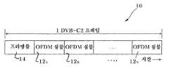
도 1은 DVB-C2 신호의 프레임 구조를 나타낸다.
도 2a-2c는 본 발명의 다양한 실시예에 따라 프리앰블을 생성하는 방법을 나타내는 블럭도를 나타낸다.
도 3은 주파수 영역에서 DVB-C2 프리앰블의 구성을 나타낸다.
도 4는 본 발명의 일 실시예에 따라 결합 채널을 갖는 프리앰블의 주기적 표현에 대한 일 예이다.
도 5는 본 발명의 일 실시예에 따른 프리앰블 신호의 구조를 나타낸 것이다.
도 6은 본 발명의 일 실시예에 따라 월시 코드(Walsh codes)를 이용한 프리앰블의 예이다.
도 7은 본 발명의 일 실시예에 따라 프리앰블 생성을 실행하기 위한 장치의 블럭도이다.BRIEF DESCRIPTION OF THE DRAWINGS The invention will be better understood with reference to the following illustrative figures.
1 shows a frame structure of a DVB-C2 signal.
2A-2C show block diagrams illustrating a method of generating a preamble in accordance with various embodiments of the present invention.
3 shows the configuration of the DVB-C2 preamble in the frequency domain.
4 is an example of a periodic representation of a preamble having a joint channel according to an embodiment of the present invention.
5 illustrates a structure of a preamble signal according to an embodiment of the present invention.
6 is an example of a preamble using Walsh codes according to an embodiment of the present invention.
7 is a block diagram of an apparatus for performing preamble generation according to an embodiment of the present invention.
본 발명은 디지털 케이블 전송 환경에서 사용되는 DVB-C2 표준에서의 프리앰블 설계를 위한 방법 및 장치에 관한 것이다.The present invention relates to a method and apparatus for preamble design in the DVB-C2 standard used in a digital cable transmission environment.
본 기재내용은 발명의 원리를 설명한다. 본 기술분야의 당업자라면, 비록 여기서는 명시적으로 기재되거나 도시되지 않는다 할지라도, 본 발명의 사상 및 범위에 포함되고 본 발명을 구현하는 다양한 배치를 고안할 수 있다는 것을 이해할 것이다.The present disclosure describes the principles of the invention. Those skilled in the art will appreciate that various arrangements can be devised which are included within the spirit and scope of the present invention and embody the invention, even if not explicitly described or illustrated herein.
여기에 기재된 모든 실시예 및 조건적 언어는, 발명자에 의해 본 기술분야를 발전시키도록 제공된 본 발명 원리 및 개념을 읽는 사람이 이해하는 것을 돕기 위한 교육적인 목적으로 제공되며, 그러한 구체적으로 언급된 실시예 및 조건에 한정되지 않는 것으로 해석된다.All embodiments and conditional language set forth herein are provided for educational purposes only and to aid the reader in understanding the principles and concepts of the present invention provided by the inventors for developing the art, It is to be understood that the invention is not limited to the examples and the conditions.
또한, 구체적인 실시예 뿐만 아니라 여기서 본 발명의 원리, 측면 및 실시예를 언급하고 있는 모든 서술내용은 구조적 및 기능적 균등물 모두를 포함하도록 의도된다. 추가적으로, 상기 균등물은 미래에 개발될 균등물 뿐만 아니라 현재 알려진 균등물 모두, 즉 구조에 상관없이 동일한 기능을 수행하는 개발된 어떠한 요소라도 포함한다.Moreover, all statements herein referring to the principles, aspects, and embodiments of the invention, as well as the specific embodiments thereof, are intended to include both structural and functional equivalents. In addition, the equivalents include not only the equivalents to be developed in the future but also all currently known equivalents, i.e., any element developed that performs the same function regardless of structure.
이와 같이, 예를 들어, 여기에 제시된 블럭도는 본 발명 원리를 구체화하는 예시적인 회로에 관한 개념도를 나타낸다는 것을 당업자라면 이해할 것이다. 마찬가지로, 모든 흐름 차트, 흐름도, 상태천이도, 의사코드 등은, 컴퓨터 판독하능 미디어에서 실질적으로 표시될 수 있고 컴퓨터나 프로세서에 의해 실행될 수 있는 다양한 프로세스를 나타내며, 이는 상기와 같은 컴퓨터나 프로세서가 명시적으로 도시되어 있는지 여부에 상관없이 그러하다.As such, it will be understood by those skilled in the art that, for example, the block diagrams presented herein represent conceptual diagrams of exemplary circuits embodying the principles of the invention. Likewise, all flow charts, flow diagrams, state transition diagrams, pseudocode, etc., represent various processes that can be substantially represented in a computer readable medium and executed by a computer or processor, Regardless of whether or not they are shown as enemies.
도면에 도시된 다양한 구성요소의 기능들은 적합한 소프트웨어와 연관하여 소프트웨어를 실행할 수 있는 하드웨어뿐만 아니라 전용 하드웨어의 사용을 통하여 제공될 수 있다. 프로세어에 의해 제공되는 경우, 상기 기능들은 단일 전용 프로세서에 의해, 단일 공유 프로세서에 의해, 또는 일부는 공유될 수도 있는 복수의 개별 프로세서에 의해 제공될 수 있다. 또한, "프로세서" 또는 "제어기"의 명시적인 사용은 소프트웨어를 실행할 수 있는 하드웨어를 배타적으로 언급하는 것으로 해석되어서는 안 되고, 제한없이 디지털 신호 프로세서(digital signal processor, DSP) 하드웨어, 소프트웨어 저장을 위한 ROM(read only memory), RAM(random access memory) 및 비휘발성 저장매체를 암시적으로 포함할 수 있다.The functions of the various components shown in the figures may be provided through use of dedicated hardware as well as hardware capable of executing the software in association with the appropriate software. When provided by a processor, the functions may be provided by a single dedicated processor, by a single shared processor, or by a plurality of individual processors, some of which may be shared. Also, the explicit use of a "processor" or "controller" should not be interpreted as referring exclusively to hardware capable of executing software, Read only memory (ROM), random access memory (RAM), and non-volatile storage media.
종래 및/또는 통상의 다른 하드웨어도 또한 포함될 수 있다. 마찬가지로, 도면에 도시된 어떠한 스위치들도 단지 개념적인 것이다. 그것들의 기능은 프로그램 로직의 동작을 통해, 전용 로직을 통해, 프로그래 제어와 전용 로직의 상호작용을 통해, 또는 심지어는 수동으로 수행될 수 있고, 그 구체적인 기술은 문맥을 통해 더욱 명확하게 이해될 수 있는 바와 같이 실행자에 의해 선택될 수 있다.Other conventional and / or conventional hardware may also be included. Likewise, any of the switches shown in the figures are merely conceptual. Their functions can be performed through the operation of program logic, through dedicated logic, through the interaction of programming control with dedicated logic, or even manually, and the specific techniques can be understood more clearly in context And may be selected by the implementer as may be.
여기서의 청구항에서, 특정 기능을 수행하기 위한 수단으로서 표현된 모든 구성요소는 상기 기능을 수행하는 어떠한 방법이라도 포함하도록 의도되고, 이는 예를 들어 a) 상기 기능을 수행하는 회로 구성요소들의 조합 또는 b) 기능을 수행하기 위해 소프트웨어를 실행하기 위한 적정 회로와 결합된 어떤 형태의 소프트웨어라도 포함하며, 이 소프트웨어는 펌웨어, 마이크로코드 등등을 포함한다. 상기 청구항에 의해 정의되는 본 발명의 원리는, 다양한 언급된 수단들에 의해 제공되는 기능들이 상기 청구항이 청구하는 바에 따라 통합되고 결합된다는 사실에 귀속된다. 따라서, 상기 기능들을 제공할 수 있는 어떠한 수단들도 여기에 설명되는 수단들과 균등하다고 여겨진다.In the claims hereof, all elements expressed as means for performing a particular function are intended to include any way of performing the function, for example: a) a combination of circuit elements performing the function, or b ) Functionality, including software, firmware, microcode, and the like, as well as any other type of software associated with the appropriate circuitry for executing the software to perform the functions described herein. The principles of the present invention as defined by the claims above relate to the fact that the functions provided by the various mentioned means are integrated and combined as claimed in the claims. Thus, any means capable of providing these functions is considered equivalent to the means described herein.
다른 다양한 변형예 뿐만 아니라 본 명세서에서 본 발명 원리에 따른 "일 실시예" 또는 "어떤 실시예"라고 언급된 것은, 상기 실시예와 관련하여 기재된 특정의 특징, 구조, 특성 등등이 본 발명의 적어도 일 실시예에 포함된다는 것을 의미한다. 이와 같이, 명세서를 통하여 다양한 곳에서 나타나는 "일 실시예에서" 또는 "어떤 실시예에서"라는 문구의 사용(다른 변형예 뿐만 아니라)은 모두 반드시 동일 실시예를 언급하는 것은 아니다.As used herein, the term "one embodiment " or" an embodiment "in accordance with the principles of the present invention, as well as other various modifications, means that a particular feature, structure, Which is included in an embodiment. Thus, the use of the phrase "in one embodiment " or" in some embodiments "(as well as other variations) appearing in various places throughout the specification are not necessarily all referring to the same embodiment.
일 실시예에 따르면, 프리앰블(preamble)이 DVB-C2 표분에서의 사용을 위해 설계된다. 본 발명의 프리앰블은 프레임 타이밍 동기화, 주파수 오프셋 추정(frequency offset estimation), 시스템 정보 시그널링 및 초기 채널 추정을 포함하는 다수의 기능을 갖는다.According to one embodiment, a preamble is designed for use in the DVB-C2 footprint. The preamble of the present invention has a number of functions including frame timing synchronization, frequency offset estimation, system information signaling, and initial channel estimation.
본 기술분야의 당업자는, 여기에 개시된 다수의 개념이 DVB-C2, 프리앰블 설계, 시그널링 및 동기화를 포함하되 이에 한정되지 않는다는 것을 알 것이다.Those skilled in the art will appreciate that many of the concepts disclosed herein include, but are not limited to, DVB-C2, preamble design, signaling, and synchronization.
본 발명의 프리앰블 설계는 케이블 채널에서의 사용을 위한 효율적인 프리앰블 구조에 대한 필요에 의해 동기부여되었다. 바람직한 일 실시예에 따르면, 본 발명의 프리앰블 구조는 이하의 기능을 구비한다:The preamble design of the present invention has been motivated by the need for an efficient preamble structure for use in cable channels. According to a preferred embodiment, the preamble structure of the present invention has the following functions:
1. 채널 결합 기술(Channel Bonding technique)이 전송기측에 적용될 때 수신기측에서의 부분적 수신(Partial Reception)을 지원하기 위해 튜닝 위치에서의 허락 수신(Allow reception);1. Allow reception at the tuning position to support Partial Reception at the receiver side when the Channel Bonding technique is applied to the transmitter side;
2. C2 시스템 식별(system identification), 프리앰블 식별 및 프레임 타이밍 동기화;C2 system identification, preamble identification and frame timing synchronization;
3. 주파수 오프셋 추정(estimation);3. frequency offset estimation;
4. 시스템 정보의 시그널링(가드 인터벌 길이, 컨스텔레이션(constellation), 코딩율 등); 및4. Signaling of system information (guard interval length, constellation, coding rate, etc.); And
5. 초기 채널 추정.
5. Initial channel estimation.
기본 프리앰블 구조Basic preamble structure
도 1에 도시된 바와 같이, DVB-C2 프레임(10)은 OFDM 심볼(12a-12n)의 묶음으로 구성되고, 제 1 OFDM 심볼은 동기화 및 C2 시스템의 시그널링을 수행하는 데에 사용되는 프리앰블 심볼(14)이다. 기재된 실시예에서, OFDM 변조의 FFT 크기는 4k로서 선택된다. 따라서, 이 실시예에 따르면, 프리앰블은 4k 반송파를 갖는 OFDM 변조를 이용하도록 설계된다.As shown in FIG. 1, the DVB-
도 2a는 프리앰블을 생성하는 실시예적인 방법(20)의 블럭도를 나타낸다. 이 실시예에서, 상보 시퀀스(complementary sequence, 22)가 헤더로서 시작 반송파에 삽입되고(도 3 참조), 그리고 나서 변조 심볼(예를 들어 BPSK 맵핑)로 맵핑된다(24). 본 기술분야의 당업자라면, 상기 상보 시퀀스가 상기 표준의 일부분이고 the Draft ESTY EN 302 755 V1.1.1_0.2(2008-10)의 표 63에서 참조될 수 있다는 것을 알 것이다. 기능적으로, 상기 맵핑된 심볼은 할당된 짝수 반송파(even carriers)에 배정되고, 이에 따라 맵핑은 상기 짝수 반송파의 할당 전에 발생한다.FIG. 2A shows a block diagram of an
시스템 정보의 시그널링 비트(26)는 오류 정정코드(28)에 의하여 보호(protect)되고 그리고 나서 직교 코드 또는 QAM 심볼의 변조 심볼로 맵핑된다(30). 도 5는 프리앰블 심볼의 구조에 관한 일 예를 나타낸다. 일 실시예에 따르면, 본 기술분야의 당업자라면, 파일럿 반송파가 채널 추정을 수행하기 위해 사용될 수 있다는 것을 인식할 것이다. 도 6은 1 비트를 운반하기 위해 길이 2의 월시코드(walsh code)를 이용하는 다른 실시예를 나타낸다. 정보 비트(0)는 코드(1,1)에 의해 전송되고 정보 비트(1)는 코드(1,-1)에 의해 전송된다. 일단 시스템의 비트 신호가 전송되면, 변조기는 시스템 비트 정보와 상보 시퀀스를 짝수 반송파(32)에 할당한다. 본 발명의 바람직한 일 실시예에 따르면 짝수 반송파만 사용되고 홀수 반송파(odd carriers)는 가상 반송파로서 남겨진다는 것을 주목하는 것은 중요하다. 마지막으로, 프리앰블 신호는 IFFT 연산(34)에 의해 시간 영역으로 변환되고, 바람직한 실시예에 따라 DVB-C2 프리앰블의 생성을 완수하기 위하여 사이클릭 프리픽스(cyclic prefix, CP)가 추가될 수 있다(36).The signaling
도 2b는 도 2a의 블럭도로부터 유도되는 방법 단계(20b)를 나타낸다. 이 실시예에서, 상보 시퀀스가 시작 반송파의 헤더로서 삽입되고(22), 시그널링 비트가 오류 정정코드로 보호되고(28), 상보 시퀀스와 시그널링 비트 모두는 변조 심볼로 맵핑되며(24, 30), 그리고 나서 그것들은 짝수 반송파에만 할당된다(32).Fig. 2b shows a method step 20b derived from the block diagram of Fig. 2a. In this embodiment, the complementary sequence is inserted (22) as a header of the starting carrier, the signaling bit is protected with an error correcting code (28), both the complementary sequence and the signaling bits are mapped (24, 30) They are then assigned only to even-numbered carriers (32).
도 2c는 본 발명에 따른 방법(20c)의 다른 실시예를 나타낸다. 이 실시예에서는, 케이블 전송에서의 2 이상의 채널이 결합되는 경우(40)에 대한 고려가 이루어진다. 이 예에서, 이하에 기재되는 바와 같이 반송파의 수를 OFDM 심볼 내에 사용되는 반송파의 수보다 적거나 같도록 제한하는 단계(42)를 추가할 필요가 있다. 주파수에 있어 반복되는 생성된 프리앰블이 결합된 채널의 전체 스펙트럼을 채우도록 보장하는 추가적인 단계(44)가 또한 요구된다.Figure 2C shows another embodiment of the
도 7은 본 발명에 따라 DVB-C2 프리앰블을 생성하기 위한 장치(70)를 나타낸다. 메모리(74) 및 변조기(76)와 통신 중인 프로세서(72)는 이하의 기준을 이용하고 그에 대한 단계를 수행함으로써 프리앰블 생성을 제어한다. 본 기술분야의 당업자라면, 필요로 하는 상보 시퀀스에서의 변동(variations)을 메모리(74)가 저장할 수 있고, 바람직한 케이블 전송 어플리케이션과 대등하도록 하게 하기 위하여 프로세서(72)는 프리앰블 생성 동안 어떤 상보 시퀀스가 사용되는지에 대하여 결정할 것이라는 것을 알 수 있을 것이다.Figure 7 shows an
바람직한 일 실시예에 따르면, 프리앰블 구조에 대하여 3가지 기준이 존재한다.According to a preferred embodiment, there are three criteria for the preamble structure.
1. 프리앰블에 의해 사용되는 반송파의 수, Kp는1. The number of carriers used by the preamble, Kp ,

에 의하여 정해진다. Ktotal은 한 OFDM 심볼에서 사용되는 반송파의 수이고, 예를 들어 DVB-T2에서 규정된 4K 모드(FFT size = 4096)에 대하여 Ktotal=3409 이다;Lt; / RTI > Ktotal is the number of carriers used in one OFDM symbol, for example Ktotal = 3409 for the 4K mode (FFT size = 4096) defined in DVB-T2;
2. 결합 채널의 스펙트럼 내에서 전송되는 신호의 정보를 운반하는 프리앰블은 전체 스펙트럼을 주기적으로 채운다. 더 나아가, 프리앰블은 전체 8 MHz, 즉 DVB-T2에서 정의된 3584 반송파를 담당할 것이다. 이 기준은2. The preamble carrying the information of the transmitted signal within the spectrum of the combining channel periodically fills the entire spectrum. Further, the preamble will be responsible for a total of 8 MHz, or 3584 carrier defined in DVB-T2. This criterion

와 같이 표현될 수 있다. Xi[k]는 i번째 결합 채널(bonding channel)의 k번째 반송파 내의 전송된 신호이며, P[l]은 i번째 반송파 내의 프리앰블 신호이다(
3. 짝수 반송파만 변조되고, 반면에 홀수 반송파는 가상 반송파로서 남겨진다.3. Only the even carriers are modulated, while the odd carriers are left as virtual carriers.
채널 결합기술이 전송기측에서 적용될 때, 상기 제 1 및 제 2 기준은 수신기측에서 부분적 수신(Partial Reception)을 지원할 필요성을 제기한다. 채널 결합 기술을 이용함으로써, 대형 스펙트럼을 제공하기 위하여 몇개의 채널이 함께 결합된다. 따라서, 이러한 대형 스펙트럼은 개별 서비스의 요구된 대역폭에 따라 서브채널 또는 데이터 슬라이스로 분할될 수 있다. 좀 더 유연성을 갖도록 하기 위해, 서브 채널 또는 데이터 슬라이스는 결합 스펙트럼 내의 어떤 지점(반송파)에서도 시작할 수 있다. 그러면, 프리앰블은 결합 스펙트럼 내에서 어떠한 튜닝 지점에서도 수신기에 의해 수신 및 탐지되어야 한다. 부분적 수신이 수신기에서 실행되면, 가드밴드(guard band)는 제거 또는 감소될 수 없다는 것은 숙지할 만하다. 따라서, 채널 결합기술이 사용되는 경우에는 스펙트럼 효율성은 명시적인 개선을 가져 오지 않는다. 채널 결합 및 부분적 수신이 사용되지 않는 경우, 또는 서브채널이 두개의 이웃하는 결합 채널의 경계를 넘을 수 없다고 하는 제한이 서브채널에 대하여 있는 경우, 상기 첫번째 두개의 기준은 면제될 수 있다. 세번째 기준은, 신속한 프리앰블 식별을 가능하게 하기 위해 프리앰블이 시간 영역 내에서 반복 구조(repetition structure)를 갖도록, 이루어진다. 이러한 종류의 구조는 IEEE802.11 및 802.16에서도 사용된다. 상기 반복구조는 쉽게 이해될 수 있다. 짝수 반송파만을 변조하고 모든 홀수 반송파는 가상 반송파로서 남겨두는 것으로 생각한다. 역DFT 방정식으로부터,When the channel combining technique is applied at the transmitter side, the first and second criteria raise the need to support partial reception at the receiver side. By using channel combining techniques, several channels are combined together to provide a large spectrum. Thus, this large spectrum can be divided into subchannels or data slices according to the required bandwidth of the individual service. To make it more flexible, a subchannel or a data slice may start at any point (carrier) within the combining spectrum. The preamble should then be received and detected by the receiver at any tuning point within the combined spectrum. It is appreciated that if partial reception is performed at the receiver, the guard band can not be removed or reduced. Thus, spectral efficiency does not lead to explicit improvement when channel combining techniques are used. The first two criteria can be exempted if channel combining and partial reception are not used, or if there is a restriction on the subchannel that the subchannel can not cross the boundary of two neighboring combining channels. The third criterion is made so that the preamble has a repetition structure in the time domain to enable fast preamble identification. This kind of structure is also used in IEEE802.11 and 802.16. The repeating structure can be easily understood. It is supposed that only the even-numbered carriers are modulated and all the odd-numbered carriers are left as virtual carriers. From the inverse DFT equation,

이다. 홀수 반송파에 대하여 X[k]=0 이기 때문에, (3)식을to be. Since X [k] = 0 for an odd-numbered carrier wave, equation (3)

와 같이 다시 쓸 수 있다.Can be rewritten as.
식 (4)에서
In equation (4)
주파수 오프셋 추정을 위한 프리앰블 구조Preamble structure for frequency offset estimation
반송파 간격(carrier spacing)에 의해 주파수 오프셋을 표준화하면, 주파수 오프셋은 정부부분과 분수부분으로 분리될 수 있다. 주파수 오프셋의 분수부분은 시간 영역 반복 구조에 의해 추정될 수 있다. 시간 영역 신호에 대한 위상 불명확함(phase ambiguity) 문제로 인해, 정수부분 주파수 오프셋의 추정은 주파수 영역 파일럿에 의존해야 한다. 본 개시내용 중 적어도 하나의 실시예에 있어서, 정수 주파수 오프셋 추정을 지원하기 위해 상보 시퀀스가 도 3에 도시된 바와 같이 주파수 영역에 할당된다. 상보 시퀀스의 길이는 채널 조건에 따라 선택될 것이다. P1 프리앰블에 대해 DVB-T2에 규정된 바와 같이, 길이 64인 8개의 직교 상보 시퀀스(orthogonal complementary sequences) 및 길이 256인 16개의 직교 상보 시퀀스가 있다. 길이 64인 상보 시퀀스의 각각은 길이 8인 8개의 상보 시퀀스 세트의 연결에 의해 만들어진다. 길이 64인 8개의 상보시퀀스는 상보 시퀀스의 8개의 직교 세트에 의해 만들어진다. 길이 256인 상보 시퀀스도 동일한 방법에 의해 만들어진다. 그것들은 길이 16인 상보 시퀀스의 16개의 직교 세트에 의해 만들어진다. DVB-C2에 대하여, 64의 길이를 갖는 시퀀스(16진법 표현으로 124721741D482E7B) 중의 하나가 선택되고 도 5와 도 6에 도시된 바와 같이 프리앰블의 시작부에 할당된다. 상보 시퀀스는 첫번째 128 반송파의 짝수 반송파에 할당된다. DVB-T2에서 실행되는 3비트 정보를 운반할 수 있는 8 직교 상보 시퀀스 대신에 상보 시퀀스를 사용한다는 것을 주목해야 한다. 상기와 같이 함으로써, 주파수 오프셋의 정부부분을 추정하기 위한 처리 시간은 감소된다.
If the frequency offset is normalized by carrier spacing, the frequency offset can be divided into a government part and a fractional part. The fractional part of the frequency offset may be estimated by a time domain iteration structure. Due to the phase ambiguity problem with the time domain signal, the estimation of the integer partial frequency offset must depend on the frequency domain pilot. In at least one embodiment of the present disclosure, a complementary sequence is assigned to the frequency domain as shown in FIG. 3 to support integer frequency offset estimation. The length of the complementary sequence will be selected according to the channel conditions. There are eight orthogonal complementary sequences of length 64 and sixteen orthogonal complementary sequences of length 256, as specified in DVB-T2 for the P1 preamble. Each of the complementary sequences of length 64 is made by connecting eight complementary sequence sets of length 8. Eight complementary sequences of length 64 are created by eight orthogonal sets of complementary sequences. A complementary sequence of length 256 is also created by the same method. They are made up of 16 orthogonal sets of complementary sequences of length 16. For DVB-C2, one of a sequence of 64 lengths (124721741D482E7B in hexadecimal notation) is selected and assigned to the beginning of the preamble, as shown in Figures 5 and 6. The complementary sequence is assigned to the even carrier of the first 128 carriers. It should be noted that a complementary sequence is used instead of 8 orthogonal complementary sequences capable of carrying 3-bit information carried on DVB-T2. By doing this, the processing time for estimating the government part of the frequency offset is reduced.
시스템 정보의 시그널링을 위한 프리앰블 구조Preamble structure for signaling system information
두가지의 시그널링 방법이 프리앰블에 제공된다.Two signaling methods are provided in the preamble.
1. P2 프리앰블 및 DVB-T2에 규정된 분산 파일럿 패턴(scattered pilot pattern) PP5를 재사용한다.1. Reuse the P2 preamble and the scattered pilot pattern PP5 specified in DVB-T2.
이 방법에서, 분산 파일럿 패턴 PP5는 DVB-C2 시스템에 적용된다. 하지만, 도 5에 도시된 바와 같이 프리앰블에는 매 12 반송파에 대하여 한 파일럿이 존재한다. 시그널링 비트는 BCH 및 LDPC 코드에 의해 보호되고 가용 짝수 반송파 내의 QAM 심볼에 맵핑된다. 상기 방법에 의한 시그널링은 더 많은 정보 비트가 전송될 수 있도록 할 수 있지만, 디코딩 복잡도는 이하에서 기재되는 시그널링 방법보다 더 크다.In this way, the distributed pilot pattern PP5 is applied to the DVB-C2 system. However, as shown in FIG. 5, there is one pilot for every 12 carriers in the preamble. The signaling bits are protected by the BCH and LDPC codes and are mapped to QAM symbols in the available even-numbered carriers. Signaling by the above method may allow more information bits to be transmitted, but the decoding complexity is greater than the signaling method described below.
2. 시스템 정보의 시그널링 비트를 운반하기 위해 직교 코드를 이용한다.2. Uses an orthogonal code to carry the signaling bits of the system information.
DVB-C2 SE(system evaluation) 그룹에 의해 권장되는 채널 모델에 따르면, rms 지연 스프레드(rms delay spread)(

이다.to be.
DVB-T2에서 정의된 4k 모드를 고려하면, 부반송파 간격(subcarrier spacing)은 대략 2.232 kHz이다. 따라서, 이웃하는 205/2.232=91 반송파가 동일한 게인(gain)과 선형 위상(linear phase)을 갖는 것으로 가정할 수 있다. 이와 같이, 예를 들어 16과 같은 적은 수의 이웃하는 부반송파에 대하여 그들이 동일한 주파수 영역 채널 게인 계수(channel gain coefficients)를 갖는 것으로 가정하는 것은 타당하다. 이러한 특성과 같은 이점을 통해, 이웃하는 부반송파 내 직교 코드들을 전송할 수 있고, 단순히 상관도를 수행함으로써 수신기에서 그것들을 디코딩할 수 있다. 예를 들어, 정보 비트 0은 코드(1,1)에 의해 전송되고 정보 비트 1은 코드(1,-1)에 의해 전송된다. 또한, 시스템 정보를 운반하는 비트는 이상적으로는 오류가 없어야 한다. 따라서, 도 2에 도시된 바와 같이 오류 정정 코드가 추가된다. 직교 코드와 오류 정정 코드의 선택은 요구되는 시스템 정보 비트의 수와 실행 복잡도에 의존한다. 여기서 길이 8인 월시 코드가 DVB-C2 프리앰블에 대하여 선택된다. 월시 코드로의 비트 맵핑은 아래의 표 1에 주어진다.Considering the 4k mode defined in DVB-T2, the subcarrier spacing is approximately 2.232 kHz. Therefore, it can be assumed that the neighboring 205 / 2.232 = 91 carriers have the same gain and linear phase. Thus, it is reasonable to assume that for a small number of neighboring subcarriers, for example 16, they have the same frequency domain channel gain coefficients. With the advantage of this feature, it is possible to transmit orthogonal codes in neighboring subcarriers and to decode them at the receiver simply by performing a correlation. For example, information bit 0 is transmitted by code (1,1) and information bit 1 is transmitted by code (1, -1). Also, bits carrying system information should ideally be error free. Therefore, an error correction code is added as shown in Fig. The choice of orthogonal code and error correction code depends on the number of system information bits required and the complexity of execution. Where a Walsh code of length 8 is selected for the DVB-C2 preamble. Bit mapping to Walsh codes is given in Table 1 below.

DVB-T2에 정의된 4k모드를 고려하고 식 (1)로부터 Ktotal을 3408(DVB-T2에서는 3409)와 동일한 값으로 선택하며, 프리앰블 내 반송파의 수는
Considering the 4k mode defined in DVB-T2 and choosing Ktotal to be equal to 3408 (3409 in DVB-T2) from equation (1), the number of carriers in the preamble is
초기 채널 추정을 위한 프리앰블 구조Preamble structure for initial channel estimation
상기 첫번째 시그널링 방법을 사용하면, 프리앰블 내 상기 파일럿 반송파 상의 채널 게인 계수는 후속하는 OFDM 심볼에서 재사용될 수 있다. 만약 상기 두번째 시그널링 방법이 사용되면, 시스템 정보 비트를 디코딩한 후에, 원본 비트 및 이렇게 전송된 직교 코드를 얻기 위하여 디코딩 비트를 인코딩할 수 있다. 그러면, 상기 변조된 부반송파 내 채널 게인 계수가 쉽게 얻어질 수 있다. 상기 첫번째 시그널링 방법을 이용하여 우리가 얻을 수 있는 것보다 훨씬 더 큰 수의 채널 게인 계수를 얻을 수 있다는 것을 주목할 필요가 있다. 케이블 채널은 안정적인 채널이기 때문에, 프리앰블에서 얻어지는 채널 게인 계수는 채널 추정을 위해 매우 유용하다. C2 시스템은 이러한 초기 채널 추정에 의한 혜택을 가질 것이다.Using the first signaling method, the channel gain coefficient on the pilot carrier in the preamble can be reused in subsequent OFDM symbols. If the second signaling method is used, after decoding the system information bits, the decoding bits may be encoded to obtain the original bits and thus transmitted orthogonal codes. Then, the channel gain coefficient in the modulated subcarrier can be easily obtained. It should be noted that we can obtain a much larger number of channel gain coefficients than we can obtain using this first signaling method. Since the cable channel is a stable channel, the channel gain coefficient obtained from the preamble is very useful for channel estimation. The C2 system will benefit from this initial channel estimation.
본 기술분야의 당업자라면, 본 발명이 공지된 케이블 전송 기술에 비해 추가적인 몇몇 이점을 제공한다는 것을 알 수 있을 것이다. 이러한 이점들 중의 몇몇 예들은 다음과 같다:Those skilled in the art will appreciate that the present invention provides several additional advantages over known cable transmission techniques. Some examples of these benefits include:
1. 본 개시 내용의 적어도 하나의 실시예에서 설계된 프리앰블은 시간 영역 내 N/2-지점 반복 구조(N/2-point repetition structure)를 제공한다(N은 FFT의 크기임). 이러한 시간 영역 구조는 동일한 시간에서 프리앰블 식별, 프레임 타이밍 동기화 및 부분 주파수 오프셋 추정을 수행하는 데에 사용될 수 있다. 추가적으로, 요구되는 복잡도는 낮고, 프레임 타이밍 동기화 및 부분 주파수 오프셋 추정의 동작특성은 CP-기반 방법보다 더 낫다.1. The preamble designed in at least one embodiment of the present disclosure provides an N / 2-point repetition structure in the time domain (N is the size of the FFT). This time domain structure can be used to perform preamble identification, frame timing synchronization and partial frequency offset estimation at the same time. Additionally, the required complexity is low, and the operating characteristics of frame timing synchronization and partial frequency offset estimation are better than the CP-based method.
2. 제공된 시그널링 방법들 중의 하나는 프리앰블 내에 전송되는 시그널링 비트를 디코딩하기 위한 것이다. 이에 따라, 복잡도는 감소되고, 프리앰블을 처리함에 있어서의 지연시간도 감소되며, 본 개시내용의 적어도 하나의 실시예는 채널 추정을 요구하지 않는다.2. One of the signaling methods provided is for decoding the signaling bits transmitted in the preamble. Thus, the complexity is reduced, the delay time in processing the preamble is also reduced, and at least one embodiment of the present disclosure does not require channel estimation.
3. 전송된 시그널링 비트에 직교 코드를 이용하는 상기 설계된 프리앰블은 추가적인 초기 채널 게인 계수(짝수 반송파 내 주파수 영역 채널 게인 계수)를 제공할 수 있다;3. The designed preamble using the orthogonal code in the transmitted signaling bits may provide an additional initial channel gain coefficient (frequency domain channel gain coefficient in the even carrier);
4. 본 개시내용의 적어도 하나의 실시예에 있어 상기 설계된 프리앰블 구조의 디코딩 복잡도는 더 작아지며, 따라서 프리앰블을 디코딩하기 위한 처리 시간(초기 지연)은 훨씬 더 짧다.4. In at least one embodiment of the present disclosure, the decoding complexity of the designed preamble structure is smaller, and therefore the processing time (initial delay) for decoding the preamble is much shorter.
본 발명 원리의 상기 및 다른 특징 및 이점들은 상기 기재내용에 기초하여 본 기술분야의 당업자라면 쉽게 확인될 수 있다. 본 발명 원리는 다양한 형태의 하드웨어, 소프트웨어, 펌웨어, 특수 목적 프로세서 또는 그들의 조합의 형태로 실행될 수 있다.These and other features and advantages of the present principles can be readily ascertained by one of ordinary skill in the art based on the above description. The principles of the invention may be implemented in the form of various forms of hardware, software, firmware, special purpose processors, or combinations thereof.
매우 바람직하게는, 본 발명의 상기 기재내용은 하드웨어 및 소프트웨어의 조합으로서 실행된다. 나아가, 소프트웨어는 프로그램 저장유닛 상에 실재적으로 구체화되는 애플리케이션 프로그램으로서 실행될 수 있다. 그 애플리케이션 프로그램은 어떤 적당한 아키텍쳐를 포함하는 장치에 업로드되고 그 장치에 의해 실행될 수 있다. 바람직하게는, 그 장치는 하나 이상의 중앙처리유닛("CPU"), 램덤 액세스 메모리("RAM") 및 입력/출력("I/O") 인터페이스와 같은 하드웨어를 갖는 컴퓨터 플랫폼 상에서 실행된다. 상기 컴퓨터 플랫폼은 또한 운영시스템(operating system) 및 마이크로명령 코드를 포함할 수 있다. 여기에 기재된 다양한 프로세스 및 기능은 마이크로명령 코드의 일부, 응용 프로그램의 일부 또는 그들의 조합일 수 있으며, 그것은 CPU에 의해 실행될 수 있다. 또한, 부가적 데이터 저장유닛 및 프린팅 유닛과 같은 다양한 다른 주변 장치가 컴퓨터 플랫폼에 연결될 수 있다.Most preferably, the above description of the present invention is implemented as a combination of hardware and software. Further, the software may be executed as an application program that is materialized on the program storage unit. The application program may be uploaded to and executed by a device containing any suitable architecture. Preferably, the apparatus is implemented on a computer platform having hardware such as one or more central processing units ("CPU"), random access memory ("RAM") and input / output ("I / O" The computer platform may also include an operating system and microcommand codes. The various processes and functions described herein may be part of the microinstruction code, part of the application program, or a combination thereof, which may be executed by the CPU. In addition, various other peripheral devices such as additional data storage units and printing units may be connected to the computer platform.
첨부된 도면에 도시된 구성적 시스템 요소 및 방법의 몇몇은 바람직하게는 소프트웨어에서 실행되기 때문에, 시스템 요소 간 또는 프로세스 기능블럭 간의 실제 연결은 본 발명이 프로그램되는 방식에 따라 달라질 수 있다. 여기에 기재된 내용이 일단 제공되면, 관련분야의 통상의 지식을 가진 자라면 본 발명의 상기 및 이와 유사한 실행예 또는 구성을 생각해 낼 수 있을 것이다.Because some of the constituent system elements and methods illustrated in the accompanying drawings are preferably implemented in software, the actual connection between system elements or between process functional blocks may vary depending on the manner in which the present invention is programmed. Those skilled in the art will appreciate that the foregoing and similar implementations or configurations of the present invention may be devised without departing from the scope of the invention.
첨부된 도면을 참조하여 예시적인 실시예가 여기에 기재되었지만, 본 발명은 그러한 구체적인 실시예에 한정되지 않으며, 본 발명의 범위 또는 사상을 벗어나지 않는 한 관련 기술분야의 통상의 지식을 가진 자에 의하여 다양한 변경 및 수정이 거기에 행해질 수 있다는 점을 이해해야 한다. 그러한 모든 변경 및 수정은 첨부된 청구범위에 기재된 바와 같은 본 발명의 범위에 포함되도록 의도된다.
While the exemplary embodiments have been described herein with reference to the accompanying drawings, it is to be understood that the invention is not limited to those precise embodiments, and that various changes in form and detail may be made by those skilled in the art without departing from the scope or spirit of the invention. It should be understood that changes and modifications may be made there. All such changes and modifications are intended to be included within the scope of the present invention as set forth in the appended claims.
Claims (35)
Translated fromKorean상기 방법은
시작 반송파에서의 헤더로서 상보 시퀀스를 삽입하는 단계(22);
시스템 정보의 시그널링 비트에 대한 오류 정정 코드를 생성하는 단계(28);
상기 상보 시퀀스와 보호된 시그널링 비트를 할당된 짝수 반송파 상에서만 변조 심볼로 맵핑하는 단계(24, 30, 32); 및
상기 프리앰블을 시간영역으로 변환하는 단계(34)를 포함하고,
상기 맵핑된 변조 심볼은 각 프레임에서 상기 프리앰블을 형성하고,
상기 보호된 시그널링 비트는 이웃하는 부반송파에 할당된 직교 코드에 동일한 주파수 영역 채널 게인 계수와 함께 맵핑되고, 상기 부반송파는 상보 시퀀스 반송파를 따르고 또한 프리앰블 전송 스펙트럼의 나머지 반송파를 통해 복제되는,
케이블 전송 매체에서의 사용을 위한 프리앰블 생성 방법.
A method of generating a preamble for use in a cable transmission medium,
The method
Inserting (22) a complementary sequence as a header in the starting carrier;
Generating (28) an error correction code for the signaling bits of the system information;
Mapping (24, 30, 32) the complementary sequence and the protected signaling bit to a modulation symbol only on the assigned even-numbered carrier; And
And converting (34) the preamble into a time domain,
Wherein the mapped modulation symbols form the preamble in each frame,
Wherein the guarded signaling bits are mapped to orthogonal codes assigned to neighboring subcarriers with the same frequency domain channel gain coefficient and the subcarriers are replicated along the complementary sequence carrier and also over the remaining carriers of the preamble transmission spectrum,
A method for generating a preamble for use in a cable transmission medium.
케이블 반송파 조건에 따라 상기 상보 시퀀스의 길이를 설정하는 단계를 더 포함하는, 케이블 전송 매체에서의 사용을 위한 프리앰블 생성 방법.
The method according to claim 1,
And setting the length of the complementary sequence in accordance with a cable carrier condition. ≪ Desc / Clms Page number 19 >
복수의 요구된 시스템 정보 비트 및 채널 조건에 응답하여 상기 직교 코드를 선택하는 단계를 더 포함하는, 케이블 전송 매체에서의 사용을 위한 프리앰블 생성 방법.
The method according to claim 1,
Further comprising selecting the orthogonal code in response to a plurality of required system information bits and channel conditions.
상기 프리앰블의 생성을 완성하기 위하여 사이클릭 프리픽스(cyclic prefix)를 추가하는 단계를 더 포함하는, 케이블 전송 매체에서의 사용을 위한 프리앰블 생성 방법.
The method according to claim 1,
Further comprising adding a cyclic prefix to complete the generation of the preamble. ≪ Desc / Clms Page number 19 >
2 이상의 채널을 결합하는 단계(40); 및
주파수에 있어 반복되는 상기 생성된 프리앰블이 상기 결합된 채널의 전체 스펙트럼을 채우도록 보장하는 단계(44)를 더 포함하는, 케이블 전송 매체에서의 사용을 위한 프리앰블 생성 방법.
The method according to claim 1,
Combining (40) two or more channels; And
Further comprising: (44) ensuring that the generated preamble repeated in frequency fills the entire spectrum of the combined channel.
상기 프리앰블에 의해 사용되는 반송파의 수가 OFDM 심볼에서 사용되는 반송파의 수보다 작거나 동일하도록 제한하는 단계(42)를 더 포함하는, 케이블 전송 매체에서의 사용을 위한 프리앰블 생성 방법.
10. The method of claim 9,
Further comprising limiting (42) the number of carriers used by the preamble to be less than or equal to the number of carriers used in the OFDM symbol.
상기 오류 정정 코드는 리드-뮬러 코드(Reed-Muller codes)를 포함하는, 케이블 전송 매체에서의 사용을 위한 프리앰블 생성 방법.
The method according to claim 1,
Wherein the error correction code comprises Reed-Muller codes. ≪ Desc / Clms Page number 19 >
상기 직교 코드는 월시 코드를 포함하는, 케이블 전송 매체에서의 사용을 위한 프리앰블 생성 방법.
The method according to claim 1,
Wherein the orthogonal code comprises a Walsh code.
시작 반송파에서의 헤더로서 상보 시퀀스를 삽입하고, 시스템 정보의 시그널링 비트에 대하여 오류 정정 코드를 생성하며, 상기 프리앰블을 형성하기 위하여 상기 상보 시퀀스와 보호된 시그널링 비트를 변조 심볼로 맵핑하기 위한 프로세서(72); 및
짝수 반송파만을 할당하고 상기 할당된 짝수 반송파 상에서 상기 프리앰블의 전송을 가능하게 하며, 상기 보호된 시그널링 비트는 이웃하는 부반송파에 할당된 직교 코드에 동일한 주파수 영역 채널 게인 계수와 함께 맵핑되고, 상기 부반송파는 상보 시퀀스 반송파를 따르고 또한 프리앰블 전송 스펙트럼의 나머지 반송파를 통하여 복제되도록 구성된 변조기(76)를 포함하는, 케이블 전송 시스템에서의 사용을 위한 프리앰블 생성 장치.
A preamble generator for use in a cable transmission system,
A processor 72 for inserting a complementary sequence as a header in the starting carrier, generating an error correction code for the signaling bits of the system information, and mapping the complementary sequence and the protected signaling bits to a modulation symbol to form the preamble ); And
The guarded bits are mapped to the orthogonal codes assigned to the neighboring subcarriers with the same frequency domain channel gain coefficients, and the subcarriers are mapped to complementary subcarriers, And a modulator (76) arranged to follow the sequence carrier and replicated through the remaining carriers of the preamble transmission spectrum.
상기 프로세서는 상기 케이블 전송 시스템에서 2 이상의 채널의 결합을 더 가능하게 하고, 주파수에 있어 반복되는 상기 생성된 프리앰블이 상기 결합된 채널의 전체 스펙트럼을 채우도록 보장하는, 케이블 전송 시스템에서의 사용을 위한 프리앰블 생성 장치.
15. The method of claim 14,
Wherein the processor is further adapted to enable coupling of two or more channels in the cable transmission system and to ensure that the generated preamble repeated in frequency fills the entire spectrum of the combined channel. Preamble generator.
상기 프로세서는 상기 프리앰블에 의해 사용되는 반송파의 수가 OFDM 심볼에서 사용되는 반송파의 수보다 작거나 동일하도록 더 제한하는, 케이블 전송 시스템에서의 사용을 위한 프리앰블 생성 장치.
15. The method of claim 14,
Wherein the processor further restricts the number of carriers used by the preamble to be less than or equal to the number of carriers used in the OFDM symbol.
시스템 정보의 상기 시그널링 비트를 운반하기 위해 직교 코드가 사용되는, 케이블 전송 시스템에서의 사용을 위한 프리앰블 생성 장치.
15. The method of claim 14,
Wherein the orthogonal code is used to carry the signaling bits of the system information.
상기 오류 정정 코드는 리드-뮬러 코드를 포함하는, 케이블 전송 시스템에서의 사용을 위한 프리앰블 생성 장치.
15. The method of claim 14,
Wherein the error correction code comprises a Reed-Muller code.
상기 방법은
시간 영역으로부터 상기 프리앰블을 변환하는 단계(34);
각 프레임 내 상기 프리앰블로부터의 할당된 짝수 반송파 상에서만의 변조 심볼을 상보 시퀀스 및 시스템 정보의 보호된 시그널링 비트로 맵핑하는 단계;
정보의 상기 보호된 시그널링 비트로부터 시스템 정보의 시그널링 비트를 획득하기 위해 오류 정정 코드를 처리하는 단계; 및
프리앰블 전송 스펙트럼의 시작 반송파 내 헤더로서의 상보 시퀀스를 제거하는 단계를 포함하되,
상기 보호된 시그널링 비트는 이웃하는 부반송파에 할당되는 직교 코드에 동일한 주파수 영역 채널 게인 계수와 함께 맵핑되고, 상기 부반송파는 상보 시퀀스 반송파를 따르고 또한 프리앰블 전송 스펙트럼의 나머지 반송파를 통하여 복제되는, 케이블 전송 매체에서의 사용을 위한 프리앰블 수신 및 처리 방법.
A method of receiving and processing a preamble for use in a cable transmission medium,
The method
Transforming (34) the preamble from a time domain;
Mapping only the modulation symbols on the assigned even-numbered carriers from the preamble in each frame to the protected signaling bits of the complementary sequence and system information;
Processing an error correction code to obtain signaling bits of system information from the protected signaling bits of information; And
Removing a complementary sequence as a header in a starting carrier of a preamble transmission spectrum,
Wherein the guarded signaling bits are mapped to orthogonal codes assigned to neighboring subcarriers with the same frequency domain channel gain coefficient and the subcarriers are replicated through the remaining carriers of the preamble transmission spectrum along a complementary sequence carrier, For receiving and processing a preamble.
짝수 반송파만을 처리하고, 할당된 상기 짝수 반송파 상에서 상기 프리앰블의 수신을 가능하게 하는 복조기(76); 및
프리앰블 전송 스펙트럼의 시작 반송파 내 헤더로서의 상보 시퀀스를 제거하고, 시스템 정보의 보호된 시그널링 비트로부터 시스템 정보의 시그널링 비트를 획득하기 위하여 오류 정정 코드를 처리하며, 상기 프리앰블을 형성하는 변조 심볼로부터 상기 상보 시퀀스와 보호된 시그널링 비트를 언맵핑(unmapping)하고,
상기 보호된 시그널링 비트는 이웃하는 부반송파에 할당되는 직교 코드에 동일한 주파수 영역 채널 게인 계수와 함께 맵핑되고, 상기 부반송파는 상보 시퀀스 반송파를 따르고 또한 프리앰블 전송 스펙트럼의 나머지 반송파를 통하여 복제되는 프로세서(72)를 포함하는, 케이블 전송 매체에서의 사용을 위한 프리앰블 생성장치.
A preamble generator for use in a cable transmission system,
A demodulator 76 for processing only even-numbered carriers and enabling reception of the preamble on the allocated even-numbered carriers; And
Processing the error correcting code to obtain a signaling bit of the system information from the protected signaling bits of the system information, removing the complementary sequence as a header in the starting carrier of the preamble transmission spectrum, And unmaps the protected signaling bits,
The protected signaling bits are mapped to orthogonal codes assigned to neighboring subcarriers with the same frequency domain channel gain coefficients and the subcarriers are copied through the remaining carriers of the preamble transmission spectrum along a complementary sequence carrier, A preamble generator for use in a cable transmission medium.
상기 직교 코드는 월시 코드(Walsh codes)를 포함하는, 케이블 전송 시스템에서의 사용을 위한 프리앰블 생성 장치.
15. The method of claim 14,
Wherein the orthogonal code comprises Walsh codes. ≪ Desc / Clms Page number 21 >
둘 이상의 채널이 결합되어 있고, 상기 생성된 프리앰블은 상기 결합된 채널의 전체 스펙트럼을 채우기 위해 주파수에 있어 반복되는, 케이블 전송 매체에서의 사용을 위한 프리앰블 수신 및 처리 방법.
22. The method of claim 21,
Wherein at least two channels are combined and the generated preamble is repeated in frequency to fill the entire spectrum of the combined channel.
상기 오류 정정 코드는 리드-뮬러 코드(Reed-Muller codes)를 포함하는, 케이블 전송 매체에서의 사용을 위한 프리앰블 수신 및 처리 방법.
22. The method of claim 21,
Wherein the error correction code comprises Reed-Muller codes. ≪ Desc / Clms Page number 20 >
상기 직교 코드는 월시 코드(Walsh codes)를 포함하는, 케이블 전송 매체에서의 사용을 위한 프리앰블 수신 및 처리 방법.
22. The method of claim 21,
Wherein the orthogonal code comprises Walsh codes. ≪ Desc / Clms Page number 20 >
둘 이상의 채널이 결합되어 있고, 상기 생성된 프리앰블은 상기 결합된 채널의 전체 스펙트럼을 채우기 위해 주파수에 있어 반복되는, 케이블 전송 시스템에서의 사용을 위한 프리앰블 생성 장치.
27. The method of claim 26,
Wherein at least two channels are combined and the generated preamble is repeated in frequency to fill the entire spectrum of the combined channel.
상기 오류 정정 코드는 리드-뮬러 코드를 포함하는, 케이블 전송 시스템에서의 사용을 위한 프리앰블 생성 장치.
27. The method of claim 26,
Wherein the error correction code comprises a Reed-Muller code.
상기 직교 코드는 월시 코드를 포함하는, 케이블 전송 시스템에서의 사용을 위한 프리앰블 생성 장치.27. The method of claim 26,
Wherein the orthogonal code comprises a Walsh code.
Applications Claiming Priority (2)
| Application Number | Priority Date | Filing Date | Title |
|---|---|---|---|
| US19674608P | 2008-10-20 | 2008-10-20 | |
| US61/196,746 | 2008-10-20 |
Publications (2)
| Publication Number | Publication Date |
|---|---|
| KR20110086091A KR20110086091A (en) | 2011-07-27 |
| KR101640595B1true KR101640595B1 (en) | 2016-07-18 |
Family
ID=42060674
Family Applications (1)
| Application Number | Title | Priority Date | Filing Date |
|---|---|---|---|
| KR1020117011383AActiveKR101640595B1 (en) | 2008-10-20 | 2009-10-20 | Method and Apparatus for Generating a Preamble for Use in Cable Transmission Systems |
Country Status (7)
| Country | Link |
|---|---|
| US (1) | US8649450B2 (en) |
| EP (1) | EP2347538B1 (en) |
| JP (1) | JP5559799B2 (en) |
| KR (1) | KR101640595B1 (en) |
| CN (1) | CN102187634B (en) |
| BR (1) | BRPI0920429B1 (en) |
| WO (1) | WO2010047787A2 (en) |
Families Citing this family (13)
| Publication number | Priority date | Publication date | Assignee | Title |
|---|---|---|---|---|
| KR101518346B1 (en) | 2008-10-20 | 2015-05-08 | 삼성전자주식회사 | A method for receiving and transmitting preamble in a OFDM system and an apparatus thereof |
| US9313531B2 (en) | 2010-10-06 | 2016-04-12 | Thomson Licensing | Device and method for content delivery adapted for synchronous playbacks |
| EP3965324A3 (en) | 2010-12-10 | 2022-03-23 | Sun Patent Trust | Signal generation method and signal generation device |
| JP5648500B2 (en)* | 2011-01-28 | 2015-01-07 | 富士通セミコンダクター株式会社 | Transmission device, transmission method, reception device, and reception method |
| US20130315323A1 (en)* | 2011-04-24 | 2013-11-28 | Broadcom Corporation | Traveling pilots within single user, multiple user, multiple access, and/or MIMO wireless communications |
| EP2634945B1 (en)* | 2012-02-29 | 2014-12-24 | Mitsubishi Electric R&D Centre Europe B.V. | Method and a device for increasing the amount of information bits comprised in a symbol |
| US9912786B2 (en)* | 2012-03-13 | 2018-03-06 | Panasonic Corporation | Wireless communication device and method to detect header information errors |
| WO2016068406A1 (en)* | 2014-10-27 | 2016-05-06 | Samsung Electronics Co., Ltd. | Additional channels using preamble symbols |
| JP6401062B2 (en)* | 2015-01-06 | 2018-10-03 | Kddi株式会社 | Wireless communication apparatus, wireless communication method and program |
| WO2016204435A1 (en)* | 2015-06-18 | 2016-12-22 | 엘지전자 주식회사 | Channel bonding based signal transmission method and apparatus therefor |
| US10136287B2 (en)* | 2015-07-09 | 2018-11-20 | Electronics And Telecommunications Research Institute | Method and apparatus for close proximity communications |
| BR112019007215A2 (en)* | 2017-03-28 | 2020-02-04 | Lg Electronics Inc | method to transmit and receive signal on wireless lan system and device for the same |
| CN114846754B (en)* | 2019-12-30 | 2024-07-05 | 索尼集团公司 | Communication apparatus and communication method |
Family Cites Families (14)
| Publication number | Priority date | Publication date | Assignee | Title |
|---|---|---|---|---|
| ATE233451T1 (en) | 1996-09-02 | 2003-03-15 | St Microelectronics Nv | IMPROVEMENTS IN, OR RELATING TO, MULTI CARRIER TRANSMISSION SYSTEMS |
| US7613183B1 (en) | 2000-10-31 | 2009-11-03 | Foundry Networks, Inc. | System and method for router data aggregation and delivery |
| KR100946913B1 (en) | 2003-11-21 | 2010-03-09 | 삼성전자주식회사 | Apparatus and method for generating preamble signal for cell identification in orthogonal frequency division multiplexing system |
| KR100868679B1 (en) | 2005-06-01 | 2008-11-13 | 삼성전자주식회사 | Preamble signal transmission and reception apparatus and method in a wireless communication system |
| WO2006137708A1 (en) | 2005-06-22 | 2006-12-28 | Samsung Electronics Co., Ltd. | Method and transmission apparatus for allocating resources to transmit uplink packet data in an orthogonal frequency division multiplexing system |
| US20070070934A1 (en) | 2005-09-28 | 2007-03-29 | Pieter Van Rooyen | Method and system for a reconfigurable OFDM radio supporting diversity |
| US20070070179A1 (en)* | 2005-09-28 | 2007-03-29 | Pieter Van Rooyen | Method and system for a reconfigurable OFDM radio |
| WO2007078146A1 (en)* | 2006-01-06 | 2007-07-12 | Samsung Electronics Co., Ltd. | Method and apparatus for transmitting/receiving uplink signaling information in a single carrier fdma system |
| JP4645479B2 (en) | 2006-02-28 | 2011-03-09 | パナソニック株式会社 | Wireless device and program |
| US7974254B2 (en) | 2007-10-22 | 2011-07-05 | Nokia Corporation | Digital broadcast signaling metadata |
| US9479367B2 (en) | 2008-01-29 | 2016-10-25 | Samsung Electronics Co., Ltd. | Apparatus and method for transmitting and receiving preambles in a digital video broadcasting system |
| ES2431337T3 (en)* | 2008-06-04 | 2013-11-26 | Sony Corporation | New frame structure for multiple carrier systems |
| KR101518346B1 (en) | 2008-10-20 | 2015-05-08 | 삼성전자주식회사 | A method for receiving and transmitting preamble in a OFDM system and an apparatus thereof |
| US8340222B2 (en)* | 2009-12-24 | 2012-12-25 | Intel Corporation | Parameter and scattered pilot based symbol timing recovery |
- 2009
- 2009-10-20EPEP09752234.6Apatent/EP2347538B1/enactiveActive
- 2009-10-20WOPCT/US2009/005717patent/WO2010047787A2/enactiveApplication Filing
- 2009-10-20USUS12/998,442patent/US8649450B2/enactiveActive
- 2009-10-20CNCN200980141623.8Apatent/CN102187634B/enactiveActive
- 2009-10-20JPJP2011532098Apatent/JP5559799B2/enactiveActive
- 2009-10-20BRBRPI0920429-6Apatent/BRPI0920429B1/enactiveIP Right Grant
- 2009-10-20KRKR1020117011383Apatent/KR101640595B1/enactiveActive
Non-Patent Citations (3)
| Title |
|---|
| "Frame structure channel coding and modulation for a second generation digital terrestrial television broadcasting system (DVB-T2)", DVB Document A122, TM 3980 Rev. 5, 2008.06* |
| Kiran Challapali et al., "Evolution of spectrum-agile cognitive radios: first wireless internet standard and beyond", WICON '06 Proceedings of the 2nd annual international workshop on Wireless interne* |
| Yuh-Ren Tsai et al., "Adaptive Channel Estimation for MB-OFDM Systems in Multi-access Interfering Environments", Vehicular Technology Conference, VTC Spring 2008, IEEE, 2008.05.11.-14* |
Also Published As
| Publication number | Publication date |
|---|---|
| CN102187634B (en) | 2014-01-22 |
| WO2010047787A3 (en) | 2010-10-14 |
| JP5559799B2 (en) | 2014-07-23 |
| US8649450B2 (en) | 2014-02-11 |
| EP2347538A2 (en) | 2011-07-27 |
| CN102187634A (en) | 2011-09-14 |
| US20110194625A1 (en) | 2011-08-11 |
| BRPI0920429A2 (en) | 2020-07-14 |
| WO2010047787A2 (en) | 2010-04-29 |
| JP2012506208A (en) | 2012-03-08 |
| EP2347538B1 (en) | 2018-08-22 |
| BRPI0920429B1 (en) | 2021-01-19 |
| KR20110086091A (en) | 2011-07-27 |
Similar Documents
| Publication | Publication Date | Title |
|---|---|---|
| KR101640595B1 (en) | Method and Apparatus for Generating a Preamble for Use in Cable Transmission Systems | |
| US10938876B2 (en) | Method and system for low data rate transmission | |
| RU2637115C2 (en) | Device for transmitting and receiving signal and method for transmitting and receiving signal | |
| KR101783928B1 (en) | Modulation of signal field in a wlan frame header | |
| EP2055063B1 (en) | Data encoding method and apparatus for flash-type signaling | |
| US20110044393A1 (en) | Apparatus for transmitting and receiving a signal and method of transmitting and receiving a signal | |
| CN102292951B (en) | Synchronization Based on Multicarrier Modulation Receiver | |
| RU2497294C2 (en) | Device for transmission and reception of signal and method for transmission and reception of signal | |
| US20060291372A1 (en) | Apparatus and method for reducing pilot overhead in a wireless communication system | |
| US8391130B2 (en) | Method and apparatus for estimating and reducing interference in wireless communication systems | |
| CN102960038B (en) | Signal to be sent in carrier wave communication system | |
| PT2190135E (en) | Apparatus for transmitting and receiving a signal and method of transmitting and receiving a signal | |
| CN101141801A (en) | Channel resource block mapping method and device | |
| CN100563231C (en) | A preamble generating method and device for an OFDM access system | |
| CN102301706A (en) | Digital video broadcasting - cable system and method for processing reserved tone | |
| WO2009043311A1 (en) | Time-frequency spreading method and apparatus in ofdma system | |
| CN100559786C (en) | Frequency Division Multiple Access Method in Time Domain Synchronous Orthogonal Frequency Division Multiplexing System | |
| KR102232791B1 (en) | Transmitter, receiver and controlling method thereof | |
| JP2017225092A (en) | Transmitting apparatus, receiving apparatus, frame configuration method, chip, and program | |
| CN101567744B (en) | Method for analyzing system information symbols in DTMB system | |
| CN103763245A (en) | Anti-noise multi-media wireless radio signal framing modulation method |
Legal Events
| Date | Code | Title | Description |
|---|---|---|---|
| PA0105 | International application | Patent event date:20110519 Patent event code:PA01051R01D Comment text:International Patent Application | |
| PG1501 | Laying open of application | ||
| PA0201 | Request for examination | Patent event code:PA02012R01D Patent event date:20141016 Comment text:Request for Examination of Application | |
| E902 | Notification of reason for refusal | ||
| PE0902 | Notice of grounds for rejection | Comment text:Notification of reason for refusal Patent event date:20150911 Patent event code:PE09021S01D | |
| E701 | Decision to grant or registration of patent right | ||
| PE0701 | Decision of registration | Patent event code:PE07011S01D Comment text:Decision to Grant Registration Patent event date:20160524 | |
| GRNT | Written decision to grant | ||
| PR0701 | Registration of establishment | Comment text:Registration of Establishment Patent event date:20160712 Patent event code:PR07011E01D | |
| PR1002 | Payment of registration fee | Payment date:20160713 End annual number:3 Start annual number:1 | |
| PG1601 | Publication of registration | ||
| FPAY | Annual fee payment | Payment date:20190712 Year of fee payment:4 | |
| PR1001 | Payment of annual fee | Payment date:20190712 Start annual number:4 End annual number:4 | |
| PR1001 | Payment of annual fee | Payment date:20200701 Start annual number:5 End annual number:5 | |
| PR1001 | Payment of annual fee | Payment date:20210702 Start annual number:6 End annual number:6 | |
| PR1001 | Payment of annual fee | Payment date:20220701 Start annual number:7 End annual number:7 | |
| PR1001 | Payment of annual fee | Payment date:20240702 Start annual number:9 End annual number:9 | |
| PR1001 | Payment of annual fee | Payment date:20250701 Start annual number:10 End annual number:10 |