KR101640097B1 - Connector Assembly for CAN Communication Devices - Google Patents
Connector Assembly for CAN Communication DevicesDownload PDFInfo
- Publication number
- KR101640097B1 KR101640097B1KR1020090072070AKR20090072070AKR101640097B1KR 101640097 B1KR101640097 B1KR 101640097B1KR 1020090072070 AKR1020090072070 AKR 1020090072070AKR 20090072070 AKR20090072070 AKR 20090072070AKR 101640097 B1KR101640097 B1KR 101640097B1
- Authority
- KR
- South Korea
- Prior art keywords
- connector
- connector assembly
- device controller
- selection unit
- present
- Prior art date
- Legal status (The legal status is an assumption and is not a legal conclusion. Google has not performed a legal analysis and makes no representation as to the accuracy of the status listed.)
- Expired - Fee Related
Links
Images

Classifications
- H—ELECTRICITY
- H01—ELECTRIC ELEMENTS
- H01R—ELECTRICALLY-CONDUCTIVE CONNECTIONS; STRUCTURAL ASSOCIATIONS OF A PLURALITY OF MUTUALLY-INSULATED ELECTRICAL CONNECTING ELEMENTS; COUPLING DEVICES; CURRENT COLLECTORS
- H01R13/00—Details of coupling devices of the kinds covered by groups H01R12/70 or H01R24/00 - H01R33/00
- H01R13/66—Structural association with built-in electrical component
- B—PERFORMING OPERATIONS; TRANSPORTING
- B60—VEHICLES IN GENERAL
- B60R—VEHICLES, VEHICLE FITTINGS, OR VEHICLE PARTS, NOT OTHERWISE PROVIDED FOR
- B60R16/00—Electric or fluid circuits specially adapted for vehicles and not otherwise provided for; Arrangement of elements of electric or fluid circuits specially adapted for vehicles and not otherwise provided for
- H—ELECTRICITY
- H01—ELECTRIC ELEMENTS
- H01R—ELECTRICALLY-CONDUCTIVE CONNECTIONS; STRUCTURAL ASSOCIATIONS OF A PLURALITY OF MUTUALLY-INSULATED ELECTRICAL CONNECTING ELEMENTS; COUPLING DEVICES; CURRENT COLLECTORS
- H01R12/00—Structural associations of a plurality of mutually-insulated electrical connecting elements, specially adapted for printed circuits, e.g. printed circuit boards [PCB], flat or ribbon cables, or like generally planar structures, e.g. terminal strips, terminal blocks; Coupling devices specially adapted for printed circuits, flat or ribbon cables, or like generally planar structures; Terminals specially adapted for contact with, or insertion into, printed circuits, flat or ribbon cables, or like generally planar structures
- H01R12/70—Coupling devices
- H—ELECTRICITY
- H01—ELECTRIC ELEMENTS
- H01R—ELECTRICALLY-CONDUCTIVE CONNECTIONS; STRUCTURAL ASSOCIATIONS OF A PLURALITY OF MUTUALLY-INSULATED ELECTRICAL CONNECTING ELEMENTS; COUPLING DEVICES; CURRENT COLLECTORS
- H01R13/00—Details of coupling devices of the kinds covered by groups H01R12/70 or H01R24/00 - H01R33/00
- H01R13/66—Structural association with built-in electrical component
- H01R13/70—Structural association with built-in electrical component with built-in switch
- H—ELECTRICITY
- H01—ELECTRIC ELEMENTS
- H01R—ELECTRICALLY-CONDUCTIVE CONNECTIONS; STRUCTURAL ASSOCIATIONS OF A PLURALITY OF MUTUALLY-INSULATED ELECTRICAL CONNECTING ELEMENTS; COUPLING DEVICES; CURRENT COLLECTORS
- H01R31/00—Coupling parts supported only by co-operation with counterpart
- H01R31/06—Intermediate parts for linking two coupling parts, e.g. adapter
- H—ELECTRICITY
- H01—ELECTRIC ELEMENTS
- H01R—ELECTRICALLY-CONDUCTIVE CONNECTIONS; STRUCTURAL ASSOCIATIONS OF A PLURALITY OF MUTUALLY-INSULATED ELECTRICAL CONNECTING ELEMENTS; COUPLING DEVICES; CURRENT COLLECTORS
- H01R2201/00—Connectors or connections adapted for particular applications
- H01R2201/26—Connectors or connections adapted for particular applications for vehicles
Landscapes
- Engineering & Computer Science (AREA)
- Mechanical Engineering (AREA)
- Details Of Connecting Devices For Male And Female Coupling (AREA)
Abstract
Translated fromKoreanDescription
Translated fromKorean본 발명은 캔 통신 디바이스용 커넥터 어셈블리에 관한 것으로서, 보다 상세하게는 캔 통신 네트워크를 구성하는 각 디바이스에 별도의 식별자를 부여해줄 수 있도록 하는 커넥터 어셈블리에 관한 것이다.BACKGROUND OF THE INVENTION 1. Field of the Invention [0001] The present invention relates to a connector assembly for a CAN communication device, and more particularly, to a connector assembly for providing a separate identifier to each device constituting a CAN communication network.
캔(CAN: Controller Area Network) 통신은 차량 내의 통신 버스(Bus) 표준 방식으로서, 컨트롤러들과 디바이스들이 호스트 컴퓨터 없이 서로 통신할 수 있도록 고안된 통신 방식이다.CAN (Controller Area Network) communication is a communication bus standard system in a vehicle, and is a communication system designed so that controllers and devices can communicate with each other without a host computer.
최근에는 자동차 내부에 구비되는 전자 제어 유닛(ECU:Electronic Control Unit)의 수가 증가함으로써 전자 제어 유닛 간의 정보 공유 필요성이 증대되었고, 늘어나는 센서들에서 감지되는 데이터를 여러 전자 제어 유닛에서 공동으로 사용할 필요성이 높아졌으며, 노이즈가 많은 차량 환경에서도 에러가 적은 안정적인 통신이 요구되는 등 캔 통신을 활용할 필요성이 높아졌다. 또한 캔 버스에 연결되는 디바이스의 수 또한 증가하였다.In recent years, the number of electronic control units (ECUs) provided in automobiles has increased, necessity of sharing information among electronic control units has increased, and it is necessary to jointly use data sensed by an increasing number of sensors in various electronic control units And it is necessary to utilize can communication such as a stable communication requiring less error even in a noisy vehicle environment. The number of devices connected to the CAN bus also increased.
이에 따라 다수의 디바이스를 캔 버스에 연결하기 위하여 사용되는 커넥터 어셈블리에는, 캔 통신을 지원하는 캔 인터페이스(CAN Interface)와 디바이스를 제어하는 컨트롤러(Controller)가 함께 구성되기에 이르렀다. 이와 같은 소위 스마트 커넥터(Smart Connector)는 차량의 다양한 전자 유닛 각각에 연결되어 통신을 중계하고 차량을 제어한다.As a result, a CAN interface that supports can communication and a controller that controls the device have been combined with the connector assembly used to connect a plurality of devices to the CAN bus. The so-called Smart Connector is connected to each of various electronic units of the vehicle to relay the communication and control the vehicle.
그러나 이와 같은 스마트 커넥터들은 장착되는 위치에 따라 다른 기능을 수행하여야 하며, 이를 위해서는 스마트 커넥터 내의 디바이스 컨트롤러들이 스마트 커넥터가 연결되는 디바이스가 무엇인지 여부를 인식할 수 있어야만 하였다. 따라서 거의 동일한 기능을 수행하는 디바이스들, 예를 들어 좌측 사이드 미러와 우측 사이드 미러에 연결되는 스마트 커넥터들은 각각 별도로 제작되어야만 하였다.However, such smart connectors must perform different functions according to their mounting positions. To do so, the device controllers in the smart connector must be able to recognize the device to which the smart connector is connected. Therefore, devices that perform almost the same function, for example, smart connectors connected to the left side mirror and the right side mirror, had to be manufactured separately.
또한 이와 같이 기능적으로 다르게 제작된 스마트 커넥터들은 차량 장착시에도 작업자에게 혼란을 주지 않기 위해서는 외형적으로도 다르게 제작되어야 했다. 따라서 기존에는 거의 동일한 제어 기능을 수행하는 스마트 커넥터들도 그 장착 위치에 따라 색상, 소재, 크기, 형상 등을 달리하여 제조하고, 작업자 역시 이와 같이 다른 형상의 커넥터를 각각 해당 위치에 맞게 장착하여야 했다.In addition, the smart connectors, which were manufactured differently in this manner, had to be manufactured differently in order to avoid confusion to the operator even when the vehicle was mounted. Accordingly, in the past, smart connectors that perform almost the same control functions were manufactured in different colors, materials, sizes, shapes, and the like according to their mounting positions, and the operator had to mount the connectors of different shapes .
이와 같이 기존의 스마트 커넥터들은 장착 위치를 컨트롤러에 미리 설정하여 설정된 위치 및 디바이스 종류에 따라 제어 애플리케이션이 동작되도록 하기 위해, 각각 별도로 제조되어야 하므로, 제조 공정이 세분화되어야 하고, 그에 따라 제조 단가가 상승한다는 단점이 있었다.As described above, since the existing smart connectors must be manufactured separately in order to allow the control application to be operated according to the set position and the device type in advance by setting the mounting position in the controller, the manufacturing process must be segmented, There were disadvantages.
또한 기존의 스마트 커넥터들은 그 외형 또한 달리 제조하여야 하기 때문에 생산 작업이 복잡하고, 차량 장착시에도 작업자는 디바이스의 종류 및 위치에 따라 서로 다른 종류의 커넥터를 연결하여야 하므로 작업 공정이 번거로우며, 작업자에게 고도의 주의를 요한다는 단점이 있었다.In addition, since the existing smart connectors must be manufactured differently, the production process is complicated and the operator has to connect different kinds of connectors according to the type and position of the device even when the vehicle is mounted, so that the work process is troublesome, There was a disadvantage of requiring a high degree of attention.
따라서 본 발명은 상기와 같은 종래의 문제점을 해결하기 위하여 안출된 것으로, 본 발명의 목적은 유사한 기능을 수행하는 캔 통신 디바이스에 모두 장착가능한 커넥터 어셈블리를 제공하는 것이다.Accordingly, it is an object of the present invention to provide a connector assembly that can be mounted on a can communication device performing a similar function.
본 발명의 다른 목적은 동일하게 제조된 커넥터 어셈블리에서 커넥터 어셈블리가 장착된 디바이스의 종류 및 위치를 인식가능하도록 하는 커넥터 어셈블리를 제공하는 것이다.It is another object of the present invention to provide a connector assembly which makes it possible to recognize the type and position of a device on which a connector assembly is mounted in a connector assembly manufactured in the same manner.
상기한 바와 같은 목적을 달성하기 위한 본 발명의 특징에 따르면, 본 발명은 내부에 각각 복수의 단자와 복수의 상대 단자가 고정되고, 서로 결합하여 상기 단자와 상기 상대 단자를 전기적으로 연결시키는 제1커넥터 및 제2커넥터를 포함하여 구성되는 커넥터 어셈블리에 있어서, 상기 제2커넥터에는, 캔 메세지를 송수신하는 캔 인터페이스부와; 상기 커넥터 어셈블리에 연결되는 디바이스를 상기 캔 인터페이스부에서 수신한 캔 메세지에 포함된 데이터에 따라 제어하는 디바이스 컨트롤러가 구비되고: 상기 제1커넥터 또는 상기 제2커넥터에는, 상기 디바이스에 각각 고유의 식별자를 부여하기 위한 입력수단으로서, 사용자로부터 상기 디바이스를 식별하기 위한 ID를 입력받아 상기 디바이스 컨트롤러에 전달하는 ID 선택부가 구비된다.According to an aspect of the present invention for attaining the above-described object, the present invention provides a semiconductor device including a plurality of terminals and a plurality of mating terminals, A connector assembly comprising a connector and a second connector, wherein the second connector includes: a can interface unit for transmitting and receiving a can message; And a device controller for controlling a device connected to the connector assembly according to data contained in a can message received by the can interface unit, wherein: the first connector or the second connector is provided with a unique identifier An ID selection unit for receiving an ID for identifying the device from a user and transmitting the ID to the device controller.
이때 상기 ID 선택부는, 상기 제1커넥터에 구비되고; 상기 제2커넥터에는, 상기 ID 선택부에 입력된 ID 정보를 감지하여 상기 디바이스 컨트롤러로 전달하는 ID 수신부가 더 포함될 수 있다.Here, the ID selector may be provided in the first connector; The second connector may further include an ID receiving unit for sensing ID information input to the ID selecting unit and transmitting the ID information to the device controller.
또한 상기 ID 선택부는, 상기 제2커넥터에 구비되고; 상기 ID 선택부에 입력된 ID 정보는 상기 디바이스 컨트롤러로 전달될 수도 있다.The ID selector may be provided in the second connector; The ID information input to the ID selecting unit may be transmitted to the device controller.
그리고 상기 ID 선택부는, 2 이상의 전기적 접점에 선택적으로 연결되는 스위치를 포함하여 구성될 수도 있다.The ID selection unit may include a switch selectively connected to two or more electrical contacts.
여기서 상기 ID 선택부는, 상기 제1커넥터의 외면에서 선택적으로 돌출되는 2 이상의 돌기를 포함하여 구성되고; 상기 ID 수신부는, 상기 돌기의 돌출 여부를 검출하는 수단으로 형성될 수도 있다.Wherein the ID selection unit includes two or more protrusions that selectively protrude from the outer surface of the first connector; The ID receiving unit may be formed as a means for detecting whether or not the protrusion protrudes.
그리고 상기 디바이스 컨트롤러는, 상기 ID 선택부를 통해 입력된 ID 정보에 따라 다른 제어 애플리케이션(Application)을 수행한다.The device controller performs another control application according to the ID information input through the ID selection unit.
이상에서 상세히 설명한 바와 같이 본 발명에 의한 캔 통신 디바이스용 커넥터 어셈블리에 의하면 다음과 같은 효과를 기대할 수 있다.As described above in detail, the connector assembly for a can communication device according to the present invention can provide the following effects.
즉, 유사한 기능을 수행하는 캔 통신 디바이스에 모두 장착가능한 커넥터 어셈블리를 제공함으로써, 커넥터의 제조 공정을 단순화하고, 조립 작업자의 업무 능률을 향상할 수 있다는 장점이 있다.That is, by providing a connector assembly that can be mounted to all of the can communication devices performing similar functions, the manufacturing process of the connector can be simplified and the work efficiency of the assembly worker can be improved.
또한 본 발명에 의한 캔 통신 디바이스용 커넥터 어셈블리에 의하면 동일하게 제조된 커넥터 어셈블리에서 커넥터 어셈블리가 장착된 디바이스의 종류 및 위치를 인식가능함으로써, 범용으로 사용가능한 커넥터 어셈블리를 제공할 수 있다는 장점이 있다.In addition, according to the connector assembly for a can communication device of the present invention, it is possible to recognize a type and a position of a device mounted with a connector assembly in a connector assembly manufactured in the same manner, thereby providing a universal connector assembly.
이하에서는 상기한 바와 같은 본 발명에 의한 캔 통신 디바이스용 커넥터 어셈블리의 구체적인 실시예를 첨부된 도면을 참고하여 상세하게 설명한다.Hereinafter, a concrete embodiment of the connector assembly for a can communication device according to the present invention will be described in detail with reference to the accompanying drawings.
도 1은 본 발명의 구체적인 실시예에 의한 커넥터 어셈블리 및 이를 이용한 캔 네트워크의 구성을 개략적으로 도시한 블럭도이다.1 is a block diagram schematically showing the configuration of a connector assembly and a can network using the same according to a specific embodiment of the present invention.
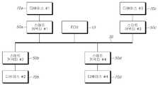
도 1에 도시된 바와 같이, 본 발명의 실시예에 의한 커넥터 어셈블리를 이용한 캔(CAN: Controller Area Network) 네트워크는 엔진, 자동변속기, ABS 등의 상태를 컴퓨터로 제어하는 하나 이상의 전자제어장치(Electronic Control Unit; 이하 'ECU'라고 한다)(10)와, 상기 ECU(10)와 각 디바이스들이 서로 캔 통신 가능하도록 하는 연결 통로가 되는 캔 버스(30)와, 자동차 내부에서 서로 통신하여 차량의 구동 및 상태를 조절하는 복수의 디바이스들(70: 70a 내지 70d)을 포함하여 구성된다.1, a CAN (Controller Area Network) network using a connector assembly according to an embodiment of the present invention includes at least one electronic control device (electronic controller) for controlling the states of an engine, an automatic transmission, A
그리고 상기 디바이스들(70)은 각각 커넥터 어셈블리(50)에 의해 상기 캔 버스(30)에 연결된다. 이와 같은 구조에 의하여 상기 ECU(10)와 상기 디바이스들(70)은 서로 신호를 송수신한다.And the devices 70 are connected to the
여기서 상기 캔 버스(30)를 통해 통신하는 복수의 디바이스(70)들은 예를 들어, 거울 조정장치, 비 탐지, 썬루프, 기상 관리 등과 같은 편의 기능 또는 고급 기능에 관련된 전장품들이나, 파워 윈도우, 좌석 조절장치, 계기 정보의 전송을 담당하는 전장품들, 파워 트레인, 안정성 제어, 엔진 관리, 변속과 같은 실시간 제어 애플리케이션을 담당하는 전장품들이 포함된다.A plurality of devices 70 communicating through the
그리고 상기 커넥터 어셈블리(50)들은 상기 디바이스(70)들의 통신이 가능하도록 연결하는 역할 뿐 아니라, 각 디바이스의 동작을 제어하는 컨트롤러를 포함하는 소위, 스마트 커넥터(Smart Connector)로 구비된다.The
이하에서 이와 같은 커넥터 어셈블리(50)의 구성을 도 2a 및 도 2b를 참조하여 보다 상세하게 설명한다.Hereinafter, the configuration of the
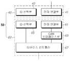
한편 도 2a는 본 발명의 제1실시예에 의한 커넥터 어셈블리의 구성을 개략적으로 도시한 블럭도이고, 도 2b는 본 발명의 제2실시예에 의한 커넥터 어셈블리의 구성을 개략적으로 도시한 블럭도이다.2A is a block diagram schematically showing a configuration of a connector assembly according to a first embodiment of the present invention, and FIG. 2B is a block diagram schematically showing a configuration of a connector assembly according to a second embodiment of the present invention .
도 2a에 도시된 바와 같이 본 발명의 제1실시예에 의한 커넥터 어셈블리(50)는 제1커넥터(40)와 제2커넥터(60)를 포함하여 구성된다. 상기 커넥터 어셈블리(50)는 상기 커넥터 어셈블리(50)에 연결되는 디바이스를 전기적으로 연결하여 구동 가능하게 하며, 또한 통신 연결하여 다른 디바이스들과 데이터 교환 및 명령 전달이 가능하도록 하고, 이미 설명한 바와 같이 디바이스의 구동을 제어하는 역할을 한다.As shown in FIG. 2A, the
이를 위하여 상기 커넥터 어셈블리(50)의 상기 제1커넥터(40) 및 상기 제2커넥터(60)에는 각각 단자연결부(41, 61)가 구비된다. 상기 단자연결부(41, 61)는 상기 캔 버스(30)에 연결된 와이어의 단부에 구비된 단자와 상기 디바이스(70)에 연결된 와이어의 단부에 구비된 단자가 각각 고정되어 상기 제1커넥터(40)와 상기 제2커넥터(60)가 물리적으로 결합하면, 상기 단자연결부(41, 61)에 고정된 각각의 단자들이 서로 연결된다.To this end, the
그리고 상기 제1커넥터(40)에는 ID 선택부(43)가 구비된다. 상기 ID 선택부(43)는 상기 커넥터 어셈블리(50)가 연결되는 디바이스(70)에 각각 고유의 식별자를 부여하기 위한 입력 수단으로서, 예를 들어 차량의 운전자측 도어와 보조석측 도어에 동일한 종류의 커넥터 어셈블리가 구비되는 경우, 운전자측에 설치되는 커넥터 어셈블리와 보조석측에 설치되는 커넥터 어셈블리에 서로 다른 ID를 부여하여 각각의 도어를 인식하고 제어할 수 있도록 하기 위한 것이다.The first connector (40) is provided with an ID selector (43). The
여기서 상기 ID는 캔 메세지 내에 포함되는 중재 ID(Arbitration ID)와는 다른 개념으로서, 상기 커넥터 어셈블리(50)에 연결되는 디바이스의 종류를 나타내는 식별자를 의미한다. 즉 상기 ID는 예를 들어, 상기 커넥터 어셈블리(50)에 연결된 디바이스가 좌측 방향등 인지, 우측 방향등 인지 여부를 나타내는 식별자이다.Here, the ID is a concept different from an arbitration ID included in a can message, and is an identifier indicating a type of a device connected to the
상기 ID 선택부(43)는 예를 들어 토글 스위치와 같은 단순한 구성에 의할 수 있으나, 이와 같은 방식에 한정되는 것은 아니고 추후 설명하는 ID 수신부(65)로 선택된 ID 정보를 전달할 수 있는 방식에 의한 것이라면 어떠한 것이라도 될 수 있다.The
한편 상기 제2커넥터(60)에는 상술한 바와 같은 단자연결부(61)와 함께 상기 단자연결부(61)에서 연결된 복수의 단자들 중 일부로부터 수신되는 캔 메세지(CAN Message), 즉 캔 통신 프로토콜에 따라 작성되어 전달된 신호를 수신하여 이를 해석하는 캔 인터페이스부(63)가 구비된다. 상기 캔 인터페이스부(63)는 캔 메세지를 수신하면, 이를 캔 통신 프로토콜에 의하여 해석하여 추후 설명하는 디바이스 컨트롤러(67)로 전달한다. 또한 디바이스 컨트롤러(67)에서 수신되는 신호를 캔 통신 프로토콜에 따라 변환하여 캔 메세지를 생성하는 역할도 수행한다.On the other hand, the
그리고 상기 제2커넥터(60)에는 ID 수신부(65)가 함께 구비되는데, 상기 ID 수신부(65)는 상기 제1커넥터(40)와 상기 제2커넥터(60)가 서로 결합하면, 상기 제1커넥터(40)의 상기 ID 선택부(43)에서 선택된 ID 정보를 감지하여 디바이스 컨트롤러(67)로 전달한다. 그에 따라 상기 디바이스 컨트롤러(67)가 해당 디바이스에 할당된 ID를 인식할 수 있도록 한다.When the
또한 상기 제2커넥터(67)에는 상기 디바이스(70)를 제어하는 디바이스 컨트롤러(67)가 구비되는데, 상기 디바이스 컨트롤러(67)는 설명한 바와 같이 상기 캔 버스(30)로부터 상기 단자연결부(41, 61)을 통해 상기 캔 인터페이스부(63)로 전달된 캔 메세지를 수신하여 수신된 캔 메세지에 포함된 데이터에 따라 상기 디바이스(70)를 제어한다. 또한 상기 디바이스(70)로부터 데이터가 발생하거나, 타 디바이스로의 명령이 발생하면 이를 상기 캔 인터페이스부(63)로 전달한다. 이에 따라 상기 캔 인터페이스부(63)는 해당 데이터나 명령을 다시 캔 메세지로 작성하여 상기 캔 버스(30)로 송신한다.The
이때 상기 디바이스 컨트롤러(67)는 상기 ID 수신부(65)로부터 수신된 ID 정보를 이용하여 디바이스(70)에 부여된 ID를 인식한다. 여기서 상기 디바이스 컨트롤러(67)는 상기 ID 선택부(43)에 입력된 ID 정보가 어떤 디바이스를 식별하기 위한 것인지 인식 가능하도록 미리 프로그래밍된다. 예를 들어 상기 ID 선택부(43)가 토글 스위치 형식으로 구비되고, 스위치 On 위치는 좌측 방향등을 나타내고 스위치 Off 위치는 우측 방향등을 나타내는 것으로 인식 가능하도록 미리 프로그래밍된다.At this time, the
그리고 상기 디바이스 컨트롤러(67)는 해당 디바이스에 대응되는 제어 애플리케이션(Application)을 수행한다. 즉, 상기 디바이스 컨트롤러(67)는 복수의 디바이스에 대한 제어가 가능하도록 미리 프로그래밍되고, 상기 ID 정보에 의해 인식된 디바이스에 대응되는 제어 동작을 수행한다.The
나아가 상기 디바이스 컨트롤러(67)는 상기 ID 정보에 따라, 수신되는 캔 메세지 중 어떤 메세지를 해당 디바이스(70)에서 이용할 것인지 여부를 판단하여 캔 메세지를 처리한다.Further, the
따라서 차량 조립시 작업자는 동일한 종류의 커넥터 어셈블리를 여러 디바이스에 장착하면서 상기 ID 선택부(43)만 간단하게 조작하면 된다. 예를 들어 동일하게 제조된 커넥터 어셈블리를 운전자측 도어와 보조석측 도어 모두에 대해 구분없이 사용하면서 상기 ID 선택부(43)를 통해 장착 위치를 표시하면 된다.Therefore, the operator can simply operate the
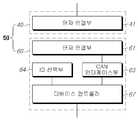
또한 본 발명의 제2실시예에 의한 커넥터 어셈블리(50)는 도 2b에 도시된 바와 같은 구조를 갖는다. 이때 이미 설명한 제1실시예와 동일한 역할을 수행하는 구성요소는 동일한 도면부호를 사용하여 설명하였다.The
본 발명의 제2실시예에 의한 커넥터 어셈블리(50)도 제1커넥터(40)와 제2커넥터(60)로 구성된다. 다만 상기 ID 선택부(64)가 제1실시예에서는 상기 제1커넥터(40)에 구비된 반면에, 제2실시예에서는 상기 제2커넥터(60)에 구성된다. 그에 따라 상기 제2커넥터(60) 내의 ID 수신부의 구성이 불필요하다.The
이와 같은 구성에 의한 커넥터 어셈블리(50)의 동작을 간단하게 요약하면, 우선 캔 버스(30)에서 캔 메세지가 상기 제1커넥터의 단자연결부(41)에 연결된 와 이어를 통해 전달되면 상기 제1커넥터의 단자연결부(41)에 물리적으로 연결된 제2커넥터의 단자연결부(61)로 전달되고, 이를 상기 캔 인터페이스부(63)가 수신한다. 캔 메세지를 수신한 상기 캔 인터페이스부(63)는 이를 해석하여 상기 디바이스 컨트롤러(67)로 전송하고, 상기 디바이스 컨트롤러(67)는 상기 ID 선택부(43 또는 64)에서 선택된 ID 정보를 이용하여 수신된 캔 메세지에 포함된 데이터에 따라 동작할지 여부를 결정한다. 수신된 캔 메세지가 상기 디바이스 컨트롤러(67)에 연결된 디바이스(70)에서 처리해야할 명령을 포함하는 경우, 해당 명령이 수행되도록 디바이스(70)를 동작시킨다.When the can message in the
한편, 상기 디바이스 컨트롤러(67)는 연결된 디바이스(70)로부터 명령이나 데이터가 수신되면 이를 상기 캔 인터페이스부(63)로 전달하여 해당 명령이나 데이터가 포함된 캔 메세지를 작성하도록 한다. 작성된 캔 메세지는 다시 상기 단자연결부(41, 61)를 통해 캔 버스(30)로 전송되고, 이는 다시 타 디바이스들로 전달된다.When the
여기서 상기 캔 인터페이스부(63)와 상기 디바이스 컨트롤러(67)는 하나의 집적회로로 구성될 수도 있다.Here, the can interface
이와 같은 커넥터 어셈블리(50)의 일실시예를 도 3을 참조하여 살펴본다.One embodiment of such a
도 3은 본 발명의 제1실시예에 의한 커넥터 어셈블리의 예시도이다. 도 3에 도시된 바와 같이 상기 커넥터 어셈블리(50)는 서로 결합되는 제1커넥터(40)와 제2커넥터(60)를 포함하여 구성된다.3 is an exemplary view of a connector assembly according to a first embodiment of the present invention. As shown in FIG. 3, the
이때 상기 제1커넥터(40)에는 상기 제1커넥터(40)의 외형을 형성하는 제1커 넥터하우징(42)이 구비된다. 상기 제1커넥터하우징(42)에는 상기 제2커넥터(60)와 마주보는 면에 이미 설명한 바와 같은 단자연결부(41)가 형성된다. 상기 단자연결부(41)에는 도면에 도시된 바와 같이 복수의 단자 수용실이 형성되고, 각각의 단자 수용실에는 전기 와이어에 단부를 형성하는 금속 단자가 각각 수용된다.At this time, the
한편 상기 제2커넥터(60)의 제2커넥터하우징(62) 내부에는 상기 제1커넥터(40)와 마주보는 면이 개구된 결합공간이 형성되고, 상기 결합공간 내부에는 다수의 단자가 고정되며, 상기 제1커넥터(40)가 상기 결합공간 내부로 결합되면, 다수의 단자가 상기 단자 수용실로 삽입되면서, 상기 제1커넥터(40)의 단자 수용실에 고정되어 있는 금속 단자들과 전기적으로 연결된다.Meanwhile, a
상기 제1커넥터(40)와 상기 제2커넥터(60)의 결합력을 높이고, 결합 상태를 유지시키기 위하여 상기 제1커넥터(40)의 상면에는 도시된 바와 같이 체결레버(46)가 형성되고, 상기 제2커넥터(64)의 상면에는 걸이공(64)이 구비될 수 있다.In order to increase the coupling force between the
또한 상기 제1커넥터하우징(42)의 일측에는 도시된 바와 같이 ID 선택부(43)가 형성된다. 하나의 예로 상기 ID 선택부(43)는 복수의 돌기로 형성될 수 있다. 복수의 돌기는 상기 제1커넥터하우징(42)의 외면에 형성되고, 상기 ID 선택부(43)에 포함되는 돌기들은 각각 사용자에 의해 가해지는 외력에 의하여 내부로 삽입되어 상기 제1커넥터하우징(42)의 외면에서 돌출되지 않은 상태로 될 수 있다.An
한편 상기 제2커넥터하우징(62)의 상기 제1커넥터(40)를 마주보는 외면에는, 상기 ID 선택부(43)에 대응하는 부분에 상기 ID 선택부(43)의 각각의 돌기들의 돌출 여부를 검출할 수 있는 ID 수신부(65)가 구비되며, 상기 ID 수신부(65)에서는 돌출된 돌기의 수 및 위치를 확인하여 사용자가 선택한 ID를 검출한다.On the outer surface of the
상기 ID 선택부(43)에 도시된 바와 같이 8개의 돌기가 구비되는 경우, 이를 이용하여 나타낼 수 있는 ID의 수는 28개, 즉 256개가 된다. 따라서 이론적으로 256개의 디바이스를 동일한 종류의 커넥터 어셈블리를 이용하여 각 디바이스를 구별 가능하게 연결할 수 있게 된다.When eight ID protrusions are provided as shown in the
즉, 사용자는 상기 ID 선택부(43)의 돌기들을 선택적으로 조작하여 원하는 ID가 선택되도록 한다. 예를 들어, 도시된 것처럼 상단의 세 개의 돌기만 돌출된 상태를 디바이스 컨트롤러(67)가 광도 센서의 ID를 선택한 것으로 인식한다면, 해당 커넥터 어셈블리(50)의 디바이스 컨트롤러(67)는 광도 센서의 제어 애플리케이션을 수행하게 된다.That is, the user selectively manipulates the protrusions of the
그러나 이미 설명한 바와 같이 상기 ID 선택부(43)는 실시예에 따라 제2커넥터(60)측에 형성될 수도 있고, 도 3을 참조하여 설명한 것과는 다른 방식으로 형성될 수도 있다.However, as described above, the
본 발명의 권리는 위에서 설명된 실시예에 한정되지 않고 청구범위에 기재된 바에 의해 정의되며, 본 발명의 분야에서 통상의 지식을 가진 자가 청구범위에 기재된 권리범위 내에서 다양한 변형과 개작을 할 수 있다는 것은 자명하다.It is to be understood that the invention is not limited to the disclosed embodiment, but is capable of many modifications and variations within the scope of the appended claims. It is self-evident.
도 1은 본 발명의 구체적인 실시예에 의한 커넥터 어셈블리 및 이를 이용한 캔 네트워크의 구성을 개략적으로 도시한 블럭도.1 is a block diagram schematically showing the configuration of a connector assembly according to a specific embodiment of the present invention and a can network using the same.
도 2a는 본 발명의 제1실시예에 의한 커넥터 어셈블리의 구성을 개략적으로 도시한 블럭도.FIG. 2A is a block diagram schematically showing the configuration of a connector assembly according to a first embodiment of the present invention; FIG.
도 2b는 본 발명의 제2실시예에 의한 커넥터 어셈블리의 구성을 개략적으로 도시한 블럭도.FIG. 2B is a block diagram schematically showing the configuration of a connector assembly according to a second embodiment of the present invention; FIG.
도 3은 본 발명의 제1실시예에 의한 커넥터 어셈블리의 예시도.3 is an exemplary view of a connector assembly according to a first embodiment of the present invention;
**도면의 주요 부분에 대한 부호의 설명**DESCRIPTION OF REFERENCE NUMERALS
10: ECU30: 캔 버스10: ECU 30: CAN bus
50: 커넥터 어셈블리70: 캔 통신 디바이스50: connector assembly 70: can communication device
40: 제1커넥터 41: 단자연결부40: first connector 41: terminal connection part
43, 64: ID 선택부60: 제2커넥터43, 64: ID selection unit 60: second connector
61: 단자연결부63: 캔 인터페이스부61: terminal connection part 63: can interface part
65: ID 수신부67: 디바이스 컨트롤러65
Claims (6)
Translated fromKoreanPriority Applications (1)
| Application Number | Priority Date | Filing Date | Title |
|---|---|---|---|
| KR1020090072070AKR101640097B1 (en) | 2009-08-05 | 2009-08-05 | Connector Assembly for CAN Communication Devices |
Applications Claiming Priority (1)
| Application Number | Priority Date | Filing Date | Title |
|---|---|---|---|
| KR1020090072070AKR101640097B1 (en) | 2009-08-05 | 2009-08-05 | Connector Assembly for CAN Communication Devices |
Publications (2)
| Publication Number | Publication Date |
|---|---|
| KR20110014721A KR20110014721A (en) | 2011-02-14 |
| KR101640097B1true KR101640097B1 (en) | 2016-07-18 |
Family
ID=43773736
Family Applications (1)
| Application Number | Title | Priority Date | Filing Date |
|---|---|---|---|
| KR1020090072070AExpired - Fee RelatedKR101640097B1 (en) | 2009-08-05 | 2009-08-05 | Connector Assembly for CAN Communication Devices |
Country Status (1)
| Country | Link |
|---|---|
| KR (1) | KR101640097B1 (en) |
Citations (3)
| Publication number | Priority date | Publication date | Assignee | Title |
|---|---|---|---|---|
| JP2006134595A (en)* | 2004-11-02 | 2006-05-25 | Auto Network Gijutsu Kenkyusho:Kk | Connector device with control function |
| JP2008284943A (en) | 2007-05-16 | 2008-11-27 | Yazaki Corp | Relay connector unit and electronic device communication system |
| JP2008293747A (en) | 2007-05-23 | 2008-12-04 | Yazaki Corp | Communication relay device and relay connector unit |
Family Cites Families (1)
| Publication number | Priority date | Publication date | Assignee | Title |
|---|---|---|---|---|
| US4956561A (en)* | 1988-12-27 | 1990-09-11 | Caterpillar Inc. | Smart power connector |
- 2009
- 2009-08-05KRKR1020090072070Apatent/KR101640097B1/ennot_activeExpired - Fee Related
Patent Citations (3)
| Publication number | Priority date | Publication date | Assignee | Title |
|---|---|---|---|---|
| JP2006134595A (en)* | 2004-11-02 | 2006-05-25 | Auto Network Gijutsu Kenkyusho:Kk | Connector device with control function |
| JP2008284943A (en) | 2007-05-16 | 2008-11-27 | Yazaki Corp | Relay connector unit and electronic device communication system |
| JP2008293747A (en) | 2007-05-23 | 2008-12-04 | Yazaki Corp | Communication relay device and relay connector unit |
Also Published As
| Publication number | Publication date |
|---|---|
| KR20110014721A (en) | 2011-02-14 |
Similar Documents
| Publication | Publication Date | Title |
|---|---|---|
| JP5022740B2 (en) | Relay connector unit, wire harness assembly, and electronic device control system | |
| CN102596647B (en) | Wiring Harnesses and Electronics Control Systems | |
| US7328086B2 (en) | Robotic tool coupler rapid-connect bus | |
| US20060088044A1 (en) | Node for a bus network, a bus network and a method for configuration of the network | |
| EP3258652B1 (en) | Local interconnect network bus architecture | |
| EP2440994B1 (en) | Vehicle communications interface and method of operation thereof | |
| US10965074B2 (en) | OBD adapter | |
| EP3862230B1 (en) | Communication system and vicarious inputting and outputting unit | |
| JP2003162303A (en) | Method and device for programming unit to be controlled | |
| WO2017064280A1 (en) | Automatic setting of identifiers for a plurality of identical electronic components in an array | |
| US20090136293A1 (en) | Two wire signal over power work tool coupling and identification | |
| CN114039993B (en) | System and method for establishing a data connection between a main unit and at least one device unit | |
| KR101640097B1 (en) | Connector Assembly for CAN Communication Devices | |
| US11209785B2 (en) | Front adapter for connecting to a control device and automation system | |
| US20180237102A1 (en) | Adapter device for connecting a vehicle control unit to a vehicle component | |
| EP3057836B1 (en) | Vehilce communications network with self-identifying switch system for vehicle control | |
| JP5177893B2 (en) | In-vehicle communication device and communication control program | |
| EP3041012A1 (en) | Self-identifying control switch | |
| JP3517969B2 (en) | Vehicle electronic control unit | |
| JP2010208357A (en) | On-vehicle equipment control system and method for setting identifier in on-vehicle equipment control system | |
| US20070115136A1 (en) | Contact signal transmission and reception apparatus | |
| KR100389970B1 (en) | An installation for k-line multy communication in car | |
| CN221162595U (en) | Vehicle base, vehicle base assembly and vehicle | |
| CN219431638U (en) | Vehicle door control equipment and vehicle | |
| CN218670593U (en) | Gear shifting control device and vehicle |
Legal Events
| Date | Code | Title | Description |
|---|---|---|---|
| PA0109 | Patent application | St.27 status event code:A-0-1-A10-A12-nap-PA0109 | |
| R17-X000 | Change to representative recorded | St.27 status event code:A-3-3-R10-R17-oth-X000 | |
| P22-X000 | Classification modified | St.27 status event code:A-2-2-P10-P22-nap-X000 | |
| PG1501 | Laying open of application | St.27 status event code:A-1-1-Q10-Q12-nap-PG1501 | |
| A201 | Request for examination | ||
| PA0201 | Request for examination | St.27 status event code:A-1-2-D10-D11-exm-PA0201 | |
| D13-X000 | Search requested | St.27 status event code:A-1-2-D10-D13-srh-X000 | |
| D14-X000 | Search report completed | St.27 status event code:A-1-2-D10-D14-srh-X000 | |
| E902 | Notification of reason for refusal | ||
| PE0902 | Notice of grounds for rejection | St.27 status event code:A-1-2-D10-D21-exm-PE0902 | |
| P22-X000 | Classification modified | St.27 status event code:A-2-2-P10-P22-nap-X000 | |
| P11-X000 | Amendment of application requested | St.27 status event code:A-2-2-P10-P11-nap-X000 | |
| P13-X000 | Application amended | St.27 status event code:A-2-2-P10-P13-nap-X000 | |
| E701 | Decision to grant or registration of patent right | ||
| PE0701 | Decision of registration | St.27 status event code:A-1-2-D10-D22-exm-PE0701 | |
| GRNT | Written decision to grant | ||
| PR0701 | Registration of establishment | St.27 status event code:A-2-4-F10-F11-exm-PR0701 | |
| PR1002 | Payment of registration fee | St.27 status event code:A-2-2-U10-U11-oth-PR1002 Fee payment year number:1 | |
| PG1601 | Publication of registration | St.27 status event code:A-4-4-Q10-Q13-nap-PG1601 | |
| FPAY | Annual fee payment | Payment date:20190625 Year of fee payment:4 | |
| PR1001 | Payment of annual fee | St.27 status event code:A-4-4-U10-U11-oth-PR1001 Fee payment year number:4 | |
| PR1001 | Payment of annual fee | St.27 status event code:A-4-4-U10-U11-oth-PR1001 Fee payment year number:5 | |
| PC1903 | Unpaid annual fee | St.27 status event code:A-4-4-U10-U13-oth-PC1903 Not in force date:20210712 Payment event data comment text:Termination Category : DEFAULT_OF_REGISTRATION_FEE | |
| PC1903 | Unpaid annual fee | St.27 status event code:N-4-6-H10-H13-oth-PC1903 Ip right cessation event data comment text:Termination Category : DEFAULT_OF_REGISTRATION_FEE Not in force date:20210712 |