KR101638251B1 - Blood dialyzing apparatus - Google Patents
Blood dialyzing apparatusDownload PDFInfo
- Publication number
- KR101638251B1 KR101638251B1KR1020140164875AKR20140164875AKR101638251B1KR 101638251 B1KR101638251 B1KR 101638251B1KR 1020140164875 AKR1020140164875 AKR 1020140164875AKR 20140164875 AKR20140164875 AKR 20140164875AKR 101638251 B1KR101638251 B1KR 101638251B1
- Authority
- KR
- South Korea
- Prior art keywords
- dialysis
- dialysis fluid
- flow tube
- dialysate
- pump
- Prior art date
- Legal status (The legal status is an assumption and is not a legal conclusion. Google has not performed a legal analysis and makes no representation as to the accuracy of the status listed.)
- Expired - Fee Related
Links
Images


Classifications
- A—HUMAN NECESSITIES
- A61—MEDICAL OR VETERINARY SCIENCE; HYGIENE
- A61M—DEVICES FOR INTRODUCING MEDIA INTO, OR ONTO, THE BODY; DEVICES FOR TRANSDUCING BODY MEDIA OR FOR TAKING MEDIA FROM THE BODY; DEVICES FOR PRODUCING OR ENDING SLEEP OR STUPOR
- A61M1/00—Suction or pumping devices for medical purposes; Devices for carrying-off, for treatment of, or for carrying-over, body-liquids; Drainage systems
- A61M1/14—Dialysis systems; Artificial kidneys; Blood oxygenators ; Reciprocating systems for treatment of body fluids, e.g. single needle systems for hemofiltration or pheresis
- A61M1/16—Dialysis systems; Artificial kidneys; Blood oxygenators ; Reciprocating systems for treatment of body fluids, e.g. single needle systems for hemofiltration or pheresis with membranes
- A61M1/1601—Control or regulation
- A—HUMAN NECESSITIES
- A61—MEDICAL OR VETERINARY SCIENCE; HYGIENE
- A61M—DEVICES FOR INTRODUCING MEDIA INTO, OR ONTO, THE BODY; DEVICES FOR TRANSDUCING BODY MEDIA OR FOR TAKING MEDIA FROM THE BODY; DEVICES FOR PRODUCING OR ENDING SLEEP OR STUPOR
- A61M1/00—Suction or pumping devices for medical purposes; Devices for carrying-off, for treatment of, or for carrying-over, body-liquids; Drainage systems
- A61M1/14—Dialysis systems; Artificial kidneys; Blood oxygenators ; Reciprocating systems for treatment of body fluids, e.g. single needle systems for hemofiltration or pheresis
- A61M1/16—Dialysis systems; Artificial kidneys; Blood oxygenators ; Reciprocating systems for treatment of body fluids, e.g. single needle systems for hemofiltration or pheresis with membranes
- A61M1/1621—Constructional aspects thereof
- A61M1/1649—Constructional aspects thereof with pulsatile dialysis fluid flow
- A—HUMAN NECESSITIES
- A61—MEDICAL OR VETERINARY SCIENCE; HYGIENE
- A61M—DEVICES FOR INTRODUCING MEDIA INTO, OR ONTO, THE BODY; DEVICES FOR TRANSDUCING BODY MEDIA OR FOR TAKING MEDIA FROM THE BODY; DEVICES FOR PRODUCING OR ENDING SLEEP OR STUPOR
- A61M1/00—Suction or pumping devices for medical purposes; Devices for carrying-off, for treatment of, or for carrying-over, body-liquids; Drainage systems
- A61M1/34—Filtering material out of the blood by passing it through a membrane, i.e. hemofiltration or diafiltration
- A—HUMAN NECESSITIES
- A61—MEDICAL OR VETERINARY SCIENCE; HYGIENE
- A61M—DEVICES FOR INTRODUCING MEDIA INTO, OR ONTO, THE BODY; DEVICES FOR TRANSDUCING BODY MEDIA OR FOR TAKING MEDIA FROM THE BODY; DEVICES FOR PRODUCING OR ENDING SLEEP OR STUPOR
- A61M60/00—Blood pumps; Devices for mechanical circulatory actuation; Balloon pumps for circulatory assistance
- A61M60/20—Type thereof
- A61M60/247—Positive displacement blood pumps
- A61M60/253—Positive displacement blood pumps including a displacement member directly acting on the blood
- A61M60/258—Piston pumps
- A—HUMAN NECESSITIES
- A61—MEDICAL OR VETERINARY SCIENCE; HYGIENE
- A61M—DEVICES FOR INTRODUCING MEDIA INTO, OR ONTO, THE BODY; DEVICES FOR TRANSDUCING BODY MEDIA OR FOR TAKING MEDIA FROM THE BODY; DEVICES FOR PRODUCING OR ENDING SLEEP OR STUPOR
- A61M60/00—Blood pumps; Devices for mechanical circulatory actuation; Balloon pumps for circulatory assistance
- A61M60/80—Constructional details other than related to driving
- A61M60/855—Constructional details other than related to driving of implantable pumps or pumping devices
- A61M60/89—Valves
- A—HUMAN NECESSITIES
- A61—MEDICAL OR VETERINARY SCIENCE; HYGIENE
- A61M—DEVICES FOR INTRODUCING MEDIA INTO, OR ONTO, THE BODY; DEVICES FOR TRANSDUCING BODY MEDIA OR FOR TAKING MEDIA FROM THE BODY; DEVICES FOR PRODUCING OR ENDING SLEEP OR STUPOR
- A61M2205/00—General characteristics of the apparatus
- A61M2205/33—Controlling, regulating or measuring
- A61M2205/3327—Measuring
- A—HUMAN NECESSITIES
- A61—MEDICAL OR VETERINARY SCIENCE; HYGIENE
- A61M—DEVICES FOR INTRODUCING MEDIA INTO, OR ONTO, THE BODY; DEVICES FOR TRANSDUCING BODY MEDIA OR FOR TAKING MEDIA FROM THE BODY; DEVICES FOR PRODUCING OR ENDING SLEEP OR STUPOR
- A61M2205/00—General characteristics of the apparatus
- A61M2205/33—Controlling, regulating or measuring
- A61M2205/3379—Masses, volumes, levels of fluids in reservoirs, flow rates
Landscapes
- Health & Medical Sciences (AREA)
- Heart & Thoracic Surgery (AREA)
- Engineering & Computer Science (AREA)
- Urology & Nephrology (AREA)
- Animal Behavior & Ethology (AREA)
- Life Sciences & Earth Sciences (AREA)
- Veterinary Medicine (AREA)
- Public Health (AREA)
- Anesthesiology (AREA)
- Biomedical Technology (AREA)
- Hematology (AREA)
- General Health & Medical Sciences (AREA)
- Vascular Medicine (AREA)
- Emergency Medicine (AREA)
- Physics & Mathematics (AREA)
- Fluid Mechanics (AREA)
- Cardiology (AREA)
- Mechanical Engineering (AREA)
- External Artificial Organs (AREA)
Abstract
Translated fromKoreanDescription
Translated fromKorean본 발명은 혈액과 투석액을 유동시킴으로써 혈액 내의 불순물을 제거하는 혈액투석 장치에 관한 것으로, 더욱 상세하게는 박동성 투석액 유동을 이용하여 혈액투석필터 내에서 투석액 압력을 신속하게 변화시키고, 이를 통해 혈액과 투석액 사이의 수분 교환과 물질 전달을 증대시키며, 혈액 펌프를 사용하지 않고 혈액을 이송시킴으로써 전체 장치를 더욱 단순화, 소형화할 수 있는 혈액투석 장치에 관한 것이다.
The present invention relates to a hemodialysis apparatus for removing impurities in blood by flowing blood and a dialysis liquid, and more particularly to a hemodialysis apparatus for rapidly changing the dialysate pressure in a hemodialysis filter using a pulsatile dialysis fluid, The present invention relates to a hemodialysis apparatus capable of further simplifying and miniaturizing the entire apparatus by transferring blood without using a blood pump.
신장 기능에 장애가 생기면 체외로 배출되어야 할 수분과 노폐물이 혈중에 축적되는 동시에, 체내의 전해질 불균형이 발생하게 된다. 이와 같은 신부전(kidney failure) 증상을 개선하는 방법으로 혈액을 체외로 순환시켜, 반투과성 막(membrane)을 갖는 투석필터(hemodialyzer)를 통하여 체내에 축적된 요독소와 잉여 수분을 제거하는 혈액투석 요법이 주로 시행되고 있다. 혈액투석은 반투과성 막의 일측으로 혈액을 타측으로 투석액을 유동시킴으로써, 이 두 유체의 농도차에 의한 확산(diffusion)과 압력차에 의한 여과(filtration)의 원리를 이용하여 체내 요독소와 잉여 수분을 제거하며 전해질 균형을 도모하는 방법이다.If a kidney function is impaired, moisture and waste products to be discharged outside the body are accumulated in the blood and an electrolyte imbalance occurs in the body. Hemodialysis therapy to remove the urinary toxin and excess water accumulated in the body through a hemodialyzer with a semipermeable membrane by circulating the blood outside the body is a method of improving the kidney failure symptom. It is mainly implemented. Hemodialysis removes the body's toxin and surplus water by using the principle of diffusion by the difference of concentration of the two fluids and filtration by the pressure difference by flowing the dialysis fluid to the other side of the semipermeable membrane on one side. And to balance the electrolyte.
혈액과 투석액이 지나는 동안 물질 이동이 용이하게 일어날 수 있도록 하나의 용기 내에 반투과성 투석막이 장착된 투석필터를 이용하게 된다. 투석필터는 원통형 용기에 중공사막의 다발을 장전하고 그 양단부에 폴리우레탄 등의 합성수지를 이용하여 포팅 가공한 중공사막형 투석필터가 주로 사용되고 있다. 중공사막형 투석필터는 전체의 크기가 소형인 것에 비해 혈액과 투석액의 유효 접촉면적이 커서 물질전달 효율이 우수하기 때문이다.A dialysis filter having a semipermeable membrane in one container is used so that mass transfer can be easily performed while the blood and the dialysis solution pass. The dialysis filter is mainly a hollow fiber membrane type dialysis filter in which a bundle of hollow fiber membranes is loaded in a cylindrical vessel and potting is performed using synthetic resin such as polyurethane at both ends thereof. This is because the hollow fiber membrane type dialysis filter has a large effective contact area between the blood and the dialysis solution, and thus has a high mass transfer efficiency.
혈액과 투석액은 투석필터를 지나면서 각각의 정수압이 감소하게 되는데, 혈액과 투석액이 투석필터 내에서 서로 반대방향으로 유동하기 때문에, 투석필터 내에서 혈액의 유입파트에서는 혈액 압력이 투석액 압력보다 높아서 혈액 중의 수분이 투석액 영역으로 이동하는 여과 현상이 발생하며, 반대로 혈액 유출파트에서는 투석액 압력이 혈액 압력보다 높기 때문에 투석액으로부터 혈액 영역으로 수분이 이동하는 역여과 현상이 일어나게 된다.As the blood and the dialysis fluid flow in opposite directions in the dialysis filter, the blood pressure in the inflow part of the blood in the dialysis filter is higher than the dialysis fluid pressure, The filtration phenomenon occurs in which the moisture in the dialysis fluid moves to the dialysis fluid area. On the other hand, since the dialysis fluid pressure is higher than the blood pressure in the blood outlet part, reverse filtration phenomenon occurs in which moisture moves from the dialysis fluid to the blood area.
혈액에서 투석액 영역으로 수분이 이동할 때, 혈액중의 노폐물이 함께 제거되는데, 이를 대류에 의한 물질전달(convective mass transfer)이라고 일컫는다. 이 대류에 의한 물질전달을 통해 신부전 환자의 중분자 요독소가 효율적으로 제거되고, 환자의 투석 효율과 예후도 크게 향상되는 것으로 알려져 있다. 하지만, 기존 혈액투석 장치에서는 투석필터의 크기가 한정되어 있고, 환자의 체중과 혈관 상태를 감안할 때 혈류량을 증가시키는 것이 제한적이기 때문에, 대류에 의한 투석효율을 향상시키는데 큰 어려움이 있다.When water moves from the blood to the dialysate area, the waste products in the blood are removed together, which is referred to as convective mass transfer. It is known that the mass transfer by the convection efficiently removes the mediastinal urinary toxin from patients with renal failure and the dialysis efficacy and prognosis of patients are greatly improved. However, since the size of the dialysis filter is limited in the conventional hemodialysis apparatus and it is limited to increase the blood flow rate in consideration of the body weight and the vascular condition of the patient, there is a great difficulty in improving the dialysis efficiency by convection.
뿐만 아니라, 혈액투석 장치는 전술한 투석필터외에 혈액을 이송시키기 위한 혈액 펌프, 투석액을 공급하고 배출하기 위한 투석액 펌프, 수분 제거량을 측정하기 위한 UF controller 등 여러 요소들을 요구하며, 따라서 투석치료를 위한 전체 장치가 크고 복잡해지는 문제를 앉고 있다. 이는 곧 혈액투석 장치를 소형화하여 환자가 원하는 시간과 장소에서 투석치료를 받는데 걸림돌이 되고 있다.
In addition, the hemodialysis apparatus requires various factors such as a blood pump for transferring blood, a dialysis fluid pump for supplying and discharging dialysate, and a UF controller for measuring the amount of water removed, in addition to the dialysis filter described above, The whole device is sitting on a large and complicated problem. This makes miniaturization of the hemodialysis device a barrier to receiving the dialysis treatment at the desired time and place.
본 발명은 이러한 문제를 해결하기 위한 것으로, 투석필터의 크기 혹은 혈류량을 증가시키지 않고, 혈액과 투석액 간의 압력차를 조절하여 혈액투석 효율을 향상시키고, 혈액 펌프의 사용을 배제함으로써 소형, 경량의 혈액투석 장치를 제공하는 것을 목적으로 한다.
The present invention solves this problem by improving the hemodialysis efficiency by controlling the pressure difference between the blood and the dialysis solution without increasing the size or blood flow volume of the dialysis filter and by eliminating the use of the blood pump, It is an object of the present invention to provide a dialysis apparatus.
상기와 같은 목적을 달성하기 위한 본 발명의 일실시예에 의한 혈액투석 장치는 혈액투석필터, 혈액투석필터와 환자를 연결하는 혈액 유동관, 투석액이 유동하는 투석액 유동관, 투석액을 투석필터로 공급하는 유입투석액 펌프, 투석필터를 거친 투석액을 배출시키는 유출투석액 펌프를 포함하여 구성된다. 유입투석액 펌프와 유출투석액 펌프는 내부 공간을 가지는 실린더, 실린더 내부에 왕복 이동이 가능하게 설치되며 실린더를 압축 혹은 팽창시키는 피스톤, 및 피스톤을 구동시키는 피스톤 구동기를 포함하여 구성되며, 유입투석액 펌프 실린더와 유출투석액 펌프 실린더는 동시에 압축과 팽창이 반복되는 것을 특징으로 한다.According to an aspect of the present invention, there is provided a hemodialysis apparatus comprising: a hemodialysis filter; a blood flow tube connecting the hemodialysis filter and the patient; a dialysis fluid flow tube through which the dialysis fluid flows; A dialysis fluid pump, and an effluent dialysis fluid pump for discharging the dialysis fluid through the dialysis filter. The inlet dialysate pump and the outlet dialysate pump are constituted by a cylinder having an internal space, a piston for reciprocating inside the cylinder, a piston for compressing or expanding the cylinder, and a piston driver for driving the piston, The outlet dialysate pump cylinder is characterized by simultaneous compression and expansion.
혈액 유동관은 투석필터와 환자를 연결하며 환자의 혈액이 투석필터로 공급되는 제 1 혈액 유동관과 투석필터를 거친 혈액이 환자에게 회송되는 제 2 혈액 유동관으로 구성된다. 마찬가지로, 투석액 유동관은 투석액이 유입투석액 펌프로 공급되는 제 1 투석액 유동관, 투석액이 유입투석액 펌프로부터 유출되어 투석필터로 공급되는 제 2 투석액 유동관, 투석필터의 투석액이 유출투석액 펌프로 유입되는 제 3 투석액 유동관, 투석액이 유출투석액 펌프로부터 유출되는 제 4 투석액 유동관으로 구성될 수 있다. 이때 본 발명의 일실시예에 의한 혈액투석 장치는 제 1 혈액 유동관, 제 1 투석액 유동관, 제 3 투석액 유동관과 제 2 혈액 유동관, 제 2 투석액 유동관, 제 4 투석액 유동관을 교번하여 차단하는 유로차단밸브를 추가로 포함하여 구성될 수 있다.The blood flow tube is composed of a first blood flow tube connecting the dialysis filter and the patient, the blood of which is supplied to the dialysis filter, and a second blood flow tube through which the blood passed through the dialysis filter is returned to the patient. Likewise, the dialysis fluid flow tube is composed of a first dialysis fluid flow tube through which the dialysis fluid is supplied to the dialysis fluid pump, a second dialysis fluid flow tube through which the dialysis fluid is drained from the dialysis fluid pump and supplied to the dialysis filter, a third dialysis fluid And a fourth dialysis fluid flow tube through which the dialysis fluid flows out of the outflow dialysis fluid pump. At this time, the hemodialysis apparatus according to an embodiment of the present invention includes a first blood flow tube, a first dialysis fluid flow tube, a third dialysis fluid flow tube and a second blood flow tube, a second dialysis solution flow tube, and a fourth dialysis solution flow tube, As shown in FIG.
상기 유로차단밸브는 직선 왕복 이동이 가능한 유로차단 가압부재와 가압부재에 직선력을 제공하는 가압부재 구동기를 이용하여 유동관을 차단 혹은 개방할 수 있다. 즉, 유로차단 가압부재가 제 1 혈액 유동관, 제 1 투석액 유동관, 제 3 투석액 유동관을 가압하여 내부의 유로를 차단하면, 제 2 혈액 유동관, 제 2 투석액 유동관, 제 4 투석액 유동관은 개방되며, 반대로 유로차단 가압부재가 제 2 혈액 유동관, 제 2 투석액 유동관, 제 4 투석액 유동관을 가압하여 내부의 유로를 차단하면, 제 1 혈액 유동관, 제 1 투석액 유동관, 제 3 투석액 유동관은 개방되는 것이 바람직하다.The flow path shutoff valve may block or open the flow path by using a flow path blocking member capable of linear reciprocating movement and a pressing member driver for providing a linear force to the pressing member. That is, when the flow path blocking member pressurizes the first blood flow tube, the first dialysis solution flow tube, and the third dialysis solution flow tube to shut off the internal flow path, the second blood flow tube, the second dialysis solution flow tube and the fourth dialysis solution flow tube are opened, When the flow path blocking member pressurizes the second blood flow tube, the second dialysis solution flow tube, and the fourth dialysis solution flow tube to block the flow path, the first blood flow tube, the first dialysis solution flow tube, and the third dialysis solution flow tube are preferably opened.
또한, 유로차단밸브의 구조는 하우징, 하우징의 외주면에 설치되는 유동 포트, 하우징의 내부에 위치하며 하우징 내주면과 밀폐 결합하고 상기 유동 포트 사이에 유로를 연결하는 로터, 그리고 로터를 구동하는 유로차단밸브 구동기를 포함하여 구성될 수 있다. 로터가 회전함으로써 어느 두 개의 유동 포트 사이에 유로를 연결하면 연결되지 않은 유동 포트를 통한 유로는 차단되는 것이 바람직하다.In addition, the structure of the flow path shutoff valve includes a housing, a flow port provided on the outer circumferential surface of the housing, a rotor disposed inside the housing and hermetically coupled with the inner circumferential surface of the housing and connecting the flow path between the flow ports, And a driver. It is preferable that the flow path through the unconnected flow port is blocked when the flow path is connected between any two flow ports by rotating the rotor.
또한, 본 발명에 의한 혈액투석 장치는 상기 제 3 투석액 유동관과 연결되며 내부에 투석액을 저장할 수 있는 볼륨 챔버를 추가로 포함하여 구성될 수 있다. 투석액이 유입되면 챔버는 팽창되고 반대로 투석액이 방출되면 챔버는 수축된다. 또한, 볼륨 챔버는 제 3 투석액 유동관에 연결되는 것으로 한정되지 않고, 상기 제 2 투석액 유동관과 연결되도록 변경될 수 있다.
In addition, the hemodialysis apparatus according to the present invention may further comprise a volume chamber connected to the third dialysate flow tube and capable of storing a dialysis liquid therein. When the dialysate is introduced, the chamber expands and conversely, when the dialysate is released, the chamber shrinks. Also, the volume chamber is not limited to being connected to the third dialysis fluid flow tube, but may be modified to be connected to the second dialysis fluid flow tube.
이하, 본 발명의 일실시예에 의한 혈액투석 장치의 작동에 대해 설명한다.Hereinafter, the operation of the hemodialysis apparatus according to one embodiment of the present invention will be described.
유입투석액 펌프 실린더와 유출투석액 펌프 실린더가 팽창될 때, 유로차단밸브는 제 1 혈액 유동관, 제 1 투석액 유동관, 제 3 투석액 유동관은 개방하고, 제 2 혈액 유동관, 제 2 투석액 유동관, 제 4 투석액 유동관은 차단한다. 유입투석액 펌프 실린더의 팽창으로 투석액이 실린더 내부로 유입되며, 유출투석액 펌프 실린더의 팽창으로 투석필터의 투석액이 실린더 내부로 유입된다. 이때, 볼륨 챔버에 저장된 투석액이 함께 유출투석액 펌프 실린더로 유입된다. 이와 같이, 투석액이 유출투석액 펌프 실린더로 유입될 때, 제 2 투석액 유동관이 차단되어 있으므로 투석필터의 투석액 압력은 혈액 압력에 비해 낮아지고 혈액 중의 수분과 노폐물이 투석액 영역으로 이동하는 여과(filtration)가 발생한다. 여과와 함께 혈액이 이송되는데, 환자의 혈액이 제 1 혈액 유동관을 거쳐 투석필터로 공급된다.When the inlet dialysate pump cylinder and the outlet dialysate pump cylinder are inflated, the flow path shutoff valve opens the first blood flow tube, the first dialysis fluid tube, the third dialysis fluid tube, and the second blood flow tube, the second dialysis solution flow tube, Lt; / RTI > The dialysis liquid is introduced into the cylinder by the inflow of the dialysis fluid pump cylinder, and the dialysis fluid of the dialysis filter is introduced into the cylinder by the expansion of the outflow dialysis fluid pump cylinder. At this time, the dialysis fluid stored in the volume chamber flows together with the dialysate pump cylinder. Thus, when the dialysis liquid is introduced into the dialysis fluid pump cylinder, the second dialysis fluid flow tube is blocked, so that the dialysis fluid pressure of the dialysis filter is lower than the blood pressure, and the filtration in which the moisture and waste in the blood move to the dialysis fluid area Occurs. The blood is transferred with filtration, the blood of the patient being fed to the dialysis filter through the first blood flow tube.
반대로, 유입투석액 펌프 실린더와 유출투석액 펌프 실린더가 압축될 때, 유로차단밸브는 제 1 혈액 유동관, 제 1 투석액 유동관, 제 3 투석액 유동관은 차단하고, 제 2 혈액 유동관, 제 2 투석액 유동관, 제 4 투석액 유동관은 개방한다. 유출투석액 펌프 실린더의 압축으로 실린더 내부의 투석액이 배출되며, 유입투석액 펌프 실린더의 압축으로 실린더 내부의 투석액이 투석필터로 공급된다. 이때, 투석필터를 거친 투석액의 일부가 볼륨 챔버에 저장될 수 있다. 이와 같이, 투석액이 투석필터로 공급될 때, 제 3 투석액 유동관이 차단되어 있으므로 투석필터의 투석액 압력은 혈액 압력에 비해 높아지고 투석액 중의 수분이 혈액 영역으로 이동하는 역여과(backfiltration)가 발생한다. 역여과로 인해 혈액이 이송되는데, 환자의 혈액이 개방된 제 2 혈액 유동관을 거쳐 환자에게 회송된다.Conversely, when the inlet dialysate pump cylinder and the outlet dialysate pump cylinder are compressed, the flow-through shutoff valve interrupts the first blood flow tube, the first dialysis fluid flow tube, the third dialysis fluid flow tube, and the second blood flow tube, The dialysate flow tube is open. The dialysis fluid in the cylinder is discharged by the compression of the dialysis fluid pump cylinder, and the dialysis fluid in the cylinder is supplied to the dialysis filter by the compression of the dialysis fluid pump cylinder. At this time, a part of the dialysis solution having passed through the dialysis filter can be stored in the volume chamber. Thus, when the dialysis fluid is supplied to the dialysis filter, the third dialysis fluid flow tube is blocked, so that the dialysis fluid pressure of the dialysis filter is higher than the blood pressure, and backfiltration occurs in which moisture in the dialysis fluid moves to the blood region. The blood is transferred due to the reverse filtration, and the blood of the patient is returned to the patient through the second blood flow tube that is open.
즉, 실린더가 팽창되면 여과가 발생하며 실린더가 압축되면 역여과가 발생한다. 이와 같이, 유입투석액 펌프와 유출투석액 펌프의 팽창-압축의 한 사이클이 여과-역여과의 한 사이클을 구성하며 혈액을 이송시킨다. 여과 동안 수분과 노폐물이 제거되며 역여과 동안 유실된 수분을 보충하게 된다.That is, filtration occurs when the cylinder expands, and reverse filtration occurs when the cylinder is compressed. Thus, one cycle of expansion-compression of the inlet dialysate pump and the outlet dialysate pump constitutes one cycle of filtration-reverse filtration and delivers the blood. During filtration, moisture and waste products are removed, and water lost during reverse filtration is replenished.
전술한 바와 같이, 실린더가 팽창될 때 투석필터의 투석액 압력은 감소하고, 반대로 실린더가 압축될 때 투석필터의 투석액 압력은 상승한다. 이와 같이 투석필터의 투석액 압력이 변동될 때, 본 발명의 일실시예에 의한 혈액투석 장치는 투석액 압력이 허용된 범위를 벗어나지 않도록 투석필터와 유출투석액 펌프를 잇는 제 3 투석액 유동관과 투석액이 유출투석액 펌프로부터 유출되는 제 4 투석액 유동관을 연결하는 압력릴리프 우회로를 추가로 포함하여 구성될 수 있다.As described above, the dialysate pressure of the dialysis filter decreases when the cylinder expands, and conversely, the dialysate pressure of the dialysis filter rises when the cylinder is compressed. When the dialysis fluid pressure of the dialysis filter is fluctuated, the hemodialysis apparatus according to an embodiment of the present invention may further include a third dialysis fluid flow tube connecting the dialysis filter and the outflow dialysis fluid pump so that the dialysis fluid pressure does not exceed the allowable range, And a pressure relief bypass which connects the fourth dialysate flow tube flowing out of the second dialysis fluid flow tube.
제 3 투석액 유동관의 압력, 즉 투석필터의 투석액 압력이 허용치보다 높을 경우 투석필터의 투석액이 압력릴리프 우회로를 거쳐 유출투석액 탱크로 방출되며, 반대로 투석필터의 투석액 압력이 허용치보다 낮을 경우 유출투석액 탱크의 투석액이 압력릴리프 우회로를 거쳐 투석필터로 보충된다. 이와 같이, 상기 압력릴리프 우회로를 설치함으로써 투석필터를 지나는 투석액 압력은 항상 허용된 범위내에 있도록 조절될 수 있다.When the pressure of the third dialysate flow pipe, that is, the dialysis fluid pressure of the dialysis filter is higher than the allowable value, the dialysis fluid of the dialysis filter is discharged to the outlet dialysate tank through the pressure relief bypass, and conversely, The dialysate is replenished with a dialysis filter through a pressure relief bypass. Thus, by providing the pressure relief bypass, the dialysate pressure passing through the dialysis filter can always be adjusted to be within an acceptable range.
또한, 본 발명의 일실시예에 의한 혈액투석 장치는 투석필터로 공급된 투석액의 양과 투석필터로부터 회수된 투석액의 양을 측정할 수 있는 수단을 포함하여 구성될 수 있다. 일례를 들어, 유입투석액 탱크 및 유출투석액 탱크 밸런스를 이용하여, 혈액투석동안 유입투석액 탱크로부터 사용된 투석액의 양과 유출투석액 탱크로 회수된 투석액의 양을 측정할 수 있다. 신부전 환자는 신장 기능의 부재로 인하여 체외로 수분 배설이 용의치 않기 때문에 혈액투석동안 체내의 잉여 수분을 제거하는 것이 중요하다. 혈액투석동안 공급된 투석액의 양과 회수된 투석액의 양을 이용하여 환자로부터 제거된 순수 수분의 양을 측정할 수 있다.In addition, the hemodialysis apparatus according to an embodiment of the present invention may include means for measuring the amount of the dialysis solution supplied to the dialysis filter and the amount of the dialysis solution recovered from the dialysis filter. For example, using the dialysis fluid tank and the outlet dialysis tank balance, the amount of dialysis fluid used from the dialysis fluid tank during dialysis and the amount of dialysis fluid returned to the outlet dialysis fluid tank can be measured. It is important to remove excess water from the body during hemodialysis because patients with kidney failure can not excrete water externally due to the absence of kidney function. The amount of dialysate supplied during hemodialysis and the amount of dialysate recovered can be used to determine the amount of pure water removed from the patient.
전술한 바와 같이, 신부전 환자는 혈액투석동안 체내의 잉여 수분을 제거하는 것이 중요한데, 이를 위하여, 본 발명의 일실시예에 의한 혈액투석 장치는 제 3 투석액 유동관과 제 4 투석액 유동관을 연결하는 보조 투석액 유동관, 보조 투석액 유동관에 설치되어 투석필터로부터 추가로 투석액을 제거하는 보조 투석액 펌프를 포함하여 구성될 수 있다. 유입투석액 펌프와 유출투석액 펌프의 작용에 의해 투석액이 유동할 때, 보조 투석액 펌프의 작용에 의해 투석필터로부터 추가로 투석액을 제거할 수 있다.As described above, it is important for a patient suffering from a renal failure to remove excess water in the body during hemodialysis. To this end, the hemodialysis apparatus according to an embodiment of the present invention includes an auxiliary dialysis fluid connecting a third dialysis fluid flow tube and a fourth dialysis fluid flow tube A flow pipe, and an auxiliary dialysis fluid pump installed in the auxiliary dialysis fluid flow tube to further remove the dialysis fluid from the dialysis filter. When the dialysis liquid flows by the action of the inlet dialysate pump and the outlet dialysate pump, the dialysis liquid can be further removed from the dialysis filter by the action of the auxiliary dialysis fluid pump.
끝으로, 본 발명의 일실시예에 의한 유입투석액 펌프 및 유출투석액 펌프는 실린더와 실린더를 압축 혹은 팽창시키는 피스톤으로 구성되는데 한정되지 않고, 수축 및 이완할 수 있는 유연한 재질로 이루어진 튜브와 튜브를 압축 혹은 팽창시키는 튜브 가압부재로 구성될 수 있다.
Finally, the inlet dialysate pump and the outflow dialysis fluid pump according to an embodiment of the present invention are not limited to a piston that compresses or expands a cylinder and a cylinder, but may be a tube and a tube made of a flexible material capable of contracting and relaxing, Or a tube pressing member for expanding the tube.
본 발명에 의한 혈액투석 장치는 혈액과 투석액 흐름을 조절하는 유로차단밸브, 실린더와 피스톤으로 구성된 투석액 펌프를 이용하여 투석필터 내의 투석액 압력을 신속하게 변화시킬 수 있으며, 이로 인해 혈액투석 동안 혈액과 투석액 사이에 수분 교환과 물질 전달을 증대시키고, 투석 효율을 향상시킬 수 있다. 뿐만 아니라, 혈액 펌프를 사용하지 않고 혈액을 이송시킴으로써 전체 장치를 더욱 단순화, 소형화할 수 있고 궁극적으로 이동식(portable) 혈액투석 장치를 제공할 수 있다.
The hemodialysis apparatus according to the present invention can quickly change the dialysate pressure in the dialysis filter by using a dialysis fluid pump composed of a cylinder and a piston, a flow path shutoff valve for controlling the flow of blood and dialysis fluid, Thereby increasing water exchange and mass transfer, and improving dialysis efficiency. In addition, the whole apparatus can be further simplified and miniaturized by transferring blood without using a blood pump, and ultimately, a portable hemodialysis apparatus can be provided.
도 1은 혈액투석 장치의 개략도이다.
도 2는 본 발명의 일실시예에 의한 투석필터의 단면도이다.
도 3은 본 발명의 일실시예에 의한 혈액투석 장치를 도시한 것이다.
도 4는 유로차단밸브가 설치된 본 발명의 일실시예에 의한 혈액투석 장치를 도시한 것이다.
도 5 및 도 6은 본 발명의 일실시예에 의한 유로차단밸브의 개략도이다.
도 7은 볼륨 챔버가 설치된 본 발명의 일실시예에 의한 혈액투석 장치를 나타낸 것이다.
도 8 및 도 9는 본 발명의 일실시예에 의한 혈액투석 장치의 작동을 나타낸 것이다.
도 10은 압력릴리프 우회로가 설치된 본 발명의 일시예에 의한 혈액투석 장치를 나타낸 것이다.
도 11은 압력릴리프 우회로의 개략도이다.
도 12는 압력릴리프 우회로가 제 1 및 제 2 투석액 유동관에 설치된 본 발명의 일시예에 의한 혈액투석 장치를 나타낸 것이다.
도 13은 밸런스가 설치된 본 발명의 일시예에 의한 혈액투석 장치를 나타낸 것이다.
도 14는 보조 투석액 유동관 및 보조 투석액 펌프를 갖는 본 발명의 일실시예에 의한 혈액투석 장치를 나타낸 것이다.
도 15는 튜브와 튜브 가압부재로 구성된 본 발명의 일실시예에 의한 혈액투석 장치를 나타낸 것이다.1 is a schematic view of a hemodialysis apparatus;
2 is a cross-sectional view of a dialysis filter according to an embodiment of the present invention.
FIG. 3 illustrates a hemodialysis apparatus according to an embodiment of the present invention.
FIG. 4 shows a hemodialysis apparatus according to an embodiment of the present invention in which a flow-line shutoff valve is provided.
5 and 6 are schematic views of a flow-path shutoff valve according to an embodiment of the present invention.
FIG. 7 shows a hemodialysis apparatus according to an embodiment of the present invention in which a volume chamber is installed.
8 and 9 illustrate the operation of a hemodialysis apparatus according to an embodiment of the present invention.
Fig. 10 shows a hemodialysis apparatus according to a temporary example of the present invention in which a pressure relief bypass is provided.
11 is a schematic view of a pressure relief bypass.
Fig. 12 shows a hemodialysis apparatus according to the present invention in which the pressure relief bypass is provided in the first and second dialysis fluid flow tubes.
FIG. 13 shows a hemodialysis apparatus according to a temporary example of the present invention in which a balance is provided.
Figure 14 shows a hemodialysis apparatus according to an embodiment of the present invention having an auxiliary dialysate flow tube and a secondary dialysate pump.
FIG. 15 shows a hemodialysis apparatus according to an embodiment of the present invention composed of a tube and a tube pressing member.
이하에서는 첨부된 도면을 참조하여 본 발명의 일실시예에 의한 혈액투석 장치에 대하여 상세히 설명한다.Hereinafter, a hemodialysis apparatus according to an embodiment of the present invention will be described in detail with reference to the accompanying drawings.
본 발명을 설명함에 있어서, 도면에 도시된 구성요소의 크기나 형상 등은 설명의 명료성과 편의를 위해 과장되거나 단순화되어 나타내어질 수 있다. 또한 본 발명의 구성 및 작용을 고려하여 특별히 정의된 용어들은 사용자, 운용자의 의도 또는 관례에 따라 달라질 수 있다. 이러한 용어들은 본 명세서 전반에 걸친 내용을 토대로 본 발명의 기술적 사상에 부합하는 의미와 개념으로 해석되어야 한다.In describing the present invention, the sizes and shapes of the components shown in the drawings may be exaggerated or simplified for clarity and convenience of explanation. In addition, the terms defined in consideration of the configuration and operation of the present invention may be changed according to the intention or custom of the user, the operator. These terms are to be construed in accordance with the meaning and concept consistent with the technical idea of the present invention based on the contents throughout the present specification.
도 1에 도시된 것과 같이, 통상의 혈액투석 장치(10)는 혈액과 투석액 사이에 물질 이동이 일어나는 투석필터(20), 투석필터와 환자를 연결하는 혈액 유동관, 혈액 유동관에 설치되어 혈액을 이송시키는 혈액 펌프, 초순수를 제조하기 위한 수처리 시스템을 포함하며, 수처리 시스템을 통해 생성된 초순수에 pH, 전해질 농도 등을 조정하여 투석액을 제조하게 된다. 투석액은 투석액 이송펌프(dialysate supply pump)에 의해 투석필터로 공급되고 배출된다. 도 1의 혈액투석 장치에는 유입투석액 탱크(16) 및 유출투석액 탱크(17)를 도시하였다. 즉, 투석액은 유입투석액 탱크에 저장된 후 투석필터로 공급될 수 있으며 투석필터를 거친 투석액은 유입투석액 탱크로 회수될 수 있다. 하지만, 투석액이 오염되는 것을 방지하기 위하여 투석액은 유입투석액 탱크에 저장되지 않고 곧바로 투석필터로 공급될 수 있으며, 투석필터를 거친 투석액은 유출투석액 탱크를 거치지 않고 곧바로 폐기될 수 있다.1, a
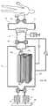
투석필터(20)는 도 2에 도시된 것과 같이, 내부 공간을 갖는 투석필터 용기(21)와 용기의 내부 공간에 수용되는 투석막(22)을 포함하며, 용기의 내부 공간은 투석막에 의해 혈액 유동영역과 투석액 유동영역으로 구획된다. 투석필터 용기의 일단과 타단에는 혈액 유입구(23)와 혈액 유출구(24)가 마련되고, 용기의 외주면 상하부에는 투석액 유입구(25)와 투석액 유출구(26)가 마련된다. 혈액 유입구로 유입되는 혈액은 투석막 안쪽의 혈액 유동영역을 통과하여 혈액 유출구를 통해 배출되고, 투석액 유입구로 유입되는 투석액은 투석막의 바깥쪽의 투석액 유동영역을 통과하여 투석액 유출구를 거쳐 배출된다.2, the
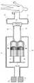
도 3에 도시된 것과 같이, 본 발명의 일실시예에 의한 혈액투석 장치(10)는 상기 혈액투석필터(20), 혈액투석필터와 환자를 연결하는 혈액 유동관(11, 12), 투석액이 유동하는 투석액 유동관(31, 32, 33, 34), 투석액을 투석필터로 공급하는 유입투석액 펌프(35), 투석필터를 거친 투석액을 배출시키는 유출투석액 펌프(36)를 포함하여 구성된다. 유입투석액 펌프와 유출투석액 펌프는 내부 공간을 가지는 실린더(35a, 36a), 실린더 내부에 왕복 이동이 가능하게 설치되며 실린더를 압축 혹은 팽창시키는 피스톤(35b, 36b), 및 피스톤을 구동시키는 피스톤 구동기를 포함하여 구성된다. 피스톤 구동기는 피스톤을 진퇴시켜 실린더를 압축 혹은 팽창시킬 수 있는 다양한 구조의 것이 이용될 수 있다. 여기서, 유입투석액 펌프 실린더(35a)와 유출투석액 펌프 실린더(36a)는 동시에 압축과 팽창이 반복되는 것을 특징으로 한다. 따라서 동일한 피스톤 및 피스톤 구동기에 의해 압축 혹은 팽창될 수 있다.3, the
또한, 도 3에서 알 수 있듯이, 혈액 유동관은 투석필터와 환자를 연결하며 환자의 혈액이 투석필터로 공급되는 제 1 혈액 유동관(11)과 투석필터를 거친 혈액이 환자에게 회송되는 제 2 혈액 유동관(12)으로 구성된다. 마찬가지로, 투석액 유동관은 투석액이 유입투석액 펌프(35)로 공급되는 제 1 투석액 유동관(31), 투석액이 유입투석액 펌프로부터 유출되어 투석필터로 공급되는 제 2 투석액 유동관(32), 투석필터의 투석액이 유출투석액 펌프로 유입되는 제 3 투석액 유동관(33), 투석액이 유출투석액 펌프로부터 유출되는 제 4 투석액 유동관(34)으로 구성될 수 있다. 여기서, 각 유동관을 통한 유체의 흐름을 볼 때, 제 1 혈액 유동관(11), 제 1 투석액 유동관(31), 제 3 투석액 유동관(33)을 유입관, 제 2 혈액 유동관(12), 제 2 투석액 유동관(32), 제 4 투석액 유동관(34)을 유출관으로 볼 수 있다. 이때 본 발명의 일실시예에 의한 혈액투석 장치(10)는 도 4에 도시한 것과 같이, 상기 유입관(즉, 제 1 혈액 유동관, 제 1 투석액 유동관, 제 3 투석액 유동관)과 상기 유출관(즉, 제 2 혈액 유동관, 제 2 투석액 유동관, 제 4 투석액 유동관)을 교번하여 차단하는 유로차단밸브(40)를 추가로 포함하여 구성될 수 있다.3, the blood flow tube connects the dialysis filter and the patient, and connects the first
상기 유로차단밸브(40)는 도 5에 도시한 것과 같이, 직선 왕복 이동이 가능한 유로차단 가압부재(41)와 가압부재에 직선력을 제공하는 가압부재 구동기를 이용하여 유동관을 차단 혹은 개방할 수 있다. 즉, 도 5(a)에 도시한 것처럼 유로차단 가압부재(41)가 제 1 혈액 유동관(11), 제 1 투석액 유동관(31), 제 3 투석액 유동관(33)을 가압하여 내부의 유로를 차단하면, 제 2 혈액 유동관(12), 제 2 투석액 유동관(32), 제 4 투석액 유동관(34)은 개방되며, 반대로 도 5(b)에 도시한 것처럼 유로차단 가압부재(41)가 제 2 혈액 유동관(12), 제 2 투석액 유동관(32), 제 4 투석액 유동관(34)을 가압하여 내부의 유로를 차단하면, 제 1 혈액 유동관(11), 제 1 투석액 유동관(31), 제 3 투석액 유동관(33)은 개방되는 것이 바람직하다.As shown in FIG. 5, the flow-
유로차단 가압부재 구동기는 유로차단 가압부재(41)에 왕복 직선 운동을 전가할 수 있는 다양한 구조의 것이 이용될 수 있다. 일례의 유로차단 가압부재 구동기는, 유로차단 가압부재를 유동관을 지지하는 유동관 지지벽(42) 쪽으로 이동시키기 위한 캠과 캠을 회전시키기 위한 모터를 포함할 수 있으며, 캠의 회전에 의해 유로차단 가압부재가 유동관을 압축하면 내부의 유로는 차단되며, 캠에 의한 외력이 제거되면 유로차단 가압부재(41)는 유동관으로부터 이격되고 유동관은 자체 탄성력으로 원래 상태로 복원되면서 유동관은 개방된다. 본 발명에 있어서, 유로차단밸브(40)의 유로 차단장치는 도시된 구조로 한정되지 않고 유동관을 압축 혹은 이완시킬 수 있는 다른 구조로 변경될 수 있다. 일례를 들어, 모터에 연결된 편심 캠이 회전하여 일측의 유동관을 압축하면 압축된 유동관 내부의 유로는 차단된다. 캠이 더 회전하면 유동관을 압축하는 캠의 외력은 제거되고 유동관은 원래 상태로 복원되면서 개방될 수 있다.The passage blocking pressure member driver may be of various structures capable of transferring reciprocating linear motion to the
또한, 유로차단밸브(40)의 구조는 도 6에 도시한 것과 같이, 하우징(43), 하우징의 외주면에 설치되는 유동 포트(44), 하우징의 내부에 위치하며 하우징 내주면과 밀폐 결합하고 상기 유동 포트 사이에 유로를 연결하는 로터(48), 그리고 로터를 구동하는 유로차단밸브 구동기(49)를 포함하여 구성될 수 있다. 로터(48)가 회전함으로써 어느 두 개의 유동 포트 사이에 유로를 연결하면 연결되지 않은 유동 포트를 통한 유로는 차단되는 것이 바람직하다. 상기 로터(48)의 회전 속도를 조절함으로써 유로의 개방 혹은 차단 시간을 조절할 수 있다.6, the structure of the flow-
도 5에 도시한 것과 같이, 본 발명의 일실시예에 의한 유로조절밸브(40)는 유로차단 가압부재(41)에 의해 상기 유입관 혹은 유출관이 동시에 차단되거나 개방될 수 있다. 이는 하우징(43)과 로터(48)로 구성된 유로차단밸브에서 한 개의 로터에 의해 3개의 유동관이 동시에 개폐되는 것과 동일하다. 하지만, 본 발명의 일실시예에 의한 유로차단밸브는 도시된 형상으로 한정되지 않는다. 일례를 들어, 혈액 흐름과 투석액 흐름을 보다 용이하게 조절하기 위하여, 상기 유로조절밸브(40)는 혈액 흐름을 조절하는 혈액 유로차단밸브와 투석액 흐름을 조절할 수 있는 투석액 유로차단밸브로 분리되어 설치될 수 있다. 또한, 도 6에서 알 수 있듯이, 유로차단밸브 하우징(43) 내에 다수개의 로터(48)가 설치되고, 이들의 회전에 의해 유입관 혹은 유출관이 차단될 수 있다. 이와 같이, 본 발명의 일실시예에 의한 유로차단밸브(40)는 제 1 혈액 유동관, 제 1 투석액 유동관, 제 3 투석액 유동관, 그리고 제 2 혈액 유동관, 제 2 투석액 유동관, 제 4 투석액 유동관을 교번하여 차단할 수 있는 다른 구조로 변경될 수 있다.As shown in FIG. 5, the
또한, 본 발명에 의한 혈액투석 장치(10)는 도 7에 도시한 것과 같이, 상기 제 3 투석액 유동관(33)과 연결되며 내부에 투석액을 저장할 수 있는 볼륨 챔버(51)를 추가로 포함하여 구성될 수 있다. 도 7에 도시한 볼륨 챔버는 투석액을 수용할 수 있는 용기와 용기 내부에 위치한 피스톤 형상의 프레임으로 구성된 것을 알 수 있는데, 투석액이 유입되면 챔버는 팽창되고 반대로 투석액이 방출되면 챔버는 수축된다. 볼륨 챔버는 도시한 형상으로 한정하지 않고 투석액을 일시적으로 저장하거나 방출할 수 있는 다른 구조로 변경될 수 있다. 또한, 상기 볼륨 챔버(60)는 제 3 투석액 유동관(33)에 연결되는 것으로 한정되지 않고, 상기 제 2 투석액 유동관(32)과 연결되도록 변경될 수 있다.
7, the
이하, 첨부된 도면을 참조하여 본 발명의 일실시예에 의한 혈액투석 장치(10)의 작동에 대해 설명한다.Hereinafter, the operation of the
도 8에 도시한 것과 같이, 유입투석액 펌프 실린더(35a)와 유출투석액 펌프 실린더(36a)가 팽창될 때, 유로차단밸브(40)는 제 1 혈액 유동관(11), 제 1 투석액 유동관(31), 제 3 투석액 유동관(33)은 개방하고, 제 2 혈액 유동관(12), 제 2 투석액 유동관(32), 제 4 투석액 유동관(34)은 차단한다. 유입투석액 펌프 실린더(35a)의 팽창으로 투석액이 실린더 내부로 유입되며, 유출투석액 펌프 실린더(36a)의 팽창으로 투석필터의 투석액이 실린더 내부로 유입된다. 이때, 볼륨 챔버(51)에 저장된 투석액이 함께 유출투석액 펌프 실린더(36a)로 유입된다. 이와 같이, 투석액이 유출투석액 펌프 실린더로 유입될 때, 제 2 투석액 유동관(32)이 차단되어 있으므로 투석필터의 투석액 압력은 혈액 압력에 비해 낮아지고 혈액 중의 수분과 노폐물이 투석액 영역으로 이동하는 여과(filtration)가 발생한다. 여과와 함께 혈액이 이송되는데, 도면에서 알 수 있듯이 환자의 혈액이 제 1 혈액 유동관(11)을 거쳐 투석필터(20)로 공급된다.8, when the inlet
반대로 도 9에 도시한 것과 같이, 유입투석액 펌프 실린더와 유출투석액 펌프 실린더가 압축될 때, 유로차단밸브(40)는 제 1 혈액 유동관(11), 제 1 투석액 유동관(31), 제 3 투석액 유동관(33)은 차단하고, 제 2 혈액 유동관(12), 제 2 투석액 유동관(32), 제 4 투석액 유동관(34)은 개방한다. 유출투석액 펌프 실린더(36a)의 압축으로 실린더 내부의 투석액이 배출되며, 유입투석액 펌프 실린더(35a)의 압축으로 실린더 내부의 투석액이 투석필터(20)로 공급된다. 이때, 투석필터를 거친 투석액의 일부가 볼륨 챔버(51)에 저장될 수 있다. 이와 같이, 투석액이 투석필터로 공급될 때, 제 3 투석액 유동관(33)이 차단되어 있으므로 투석필터의 투석액 압력은 혈액 압력에 비해 높아지고 투석액 중의 수분이 혈액 영역으로 이동하는 역여과(backfiltration)가 발생한다. 역여과로 인해 혈액이 이송되는데 도면에서 알 수 있듯이 환자의 혈액이 개방된 제 2 혈액 유동관(12)을 거쳐 환자에게 회송된다.Conversely, as shown in Fig. 9, when the inlet dialysis solution pump cylinder and the outlet dialysis solution pump cylinder are compressed, the flow
즉, 실린더(35a, 36a)가 팽창되면 투석필터의 TMP가 양(+)의 값을 갖고 여과가 발생하며, 실린더가 압축되면 TMP는 음(-)의 값을 갖고 역여과가 발생한다. 여기서, TMP는 투석필터를 지나는 혈액 압력과 투석액 압력의 차이로 정의된다. 이와 같이, 유입투석액 펌프(35)와 유출투석액 펌프(36)의 팽창-압축의 한 사이클이 여과-역여과의 한 사이클을 구성하며, 본 발명의 일실시예에 의한 혈액투석 장치(10)는 상기 팽창-압축의 사이클을 반복하게 된다. 여과 동안 수분과 노폐물이 제거되며 역여과 동안 유실된 수분을 보충하게 된다.That is, when the
통상의 혈액투석에서 혈액은 튜브 압착 방식의 롤러 펌프에 의해 이송되는데, 이때 혈액 압력은 롤러에 의한 혈액 유동관 압착과 팽창을 반복하기 때문에 소폭의 파동(fluctuation)이 존재한다. 하지만, 본 발명의 일실시예에 의한 혈액투석 장치에 의해서 만들어지는 투석액 압력은 혈액 압력의 변동 폭에 비해 현저하게 큰 것을 특징으로 한다. 이는 혈액 유동관을 압착해서 유체를 이송시키는 롤러 펌프에 비해, 실린더 압축과 팽창을 통한 투석액 이동이 현저하게 큰 박동성(pulsatility) 유동을 만들기 때문이다.In normal hemodialysis, the blood is transported by a roller pump of the tube compression type, in which there is a small fluctuation because the blood pressure repeats the blood flow tube squeezing and expansion by the roller. However, the dialysis fluid pressure produced by the hemodialysis apparatus according to an embodiment of the present invention is remarkably larger than the fluctuation width of the blood pressure. This is because the dialysis fluid flow through the compression and expansion of the cylinder produces a significantly greater pulsatility flow compared to a roller pump that squeezes the blood flow tube to transport the fluid.
여기서, 유입투석액 펌프와 유출투석액 펌프가 팽창될 때의 여과량(QUF, ml/stroke)과 압축될 때의 역여과량(QBF, ml/stroke)을 산출할 수 있다. 투석액 유동관(32, 33)과 혈액 유동관(11, 12)은 내부의 압력 변화에도 불구하고 수축 혹은 팽창하지 않으며 고정된 볼륨을 갖는다고 볼 수 있다. 유출투석액 펌프 실린더(36a)의 팽창 볼륨을 Ve, 유입투석액 펌프 실린더(35a)의 압축 볼륨을 Vd, 볼륨 챔버(51)의 수용 볼륨을 Vc라고 가정할 경우, QUF과 QBF는 다음의 식으로 계산되어 질 수 있다.
Here, it is possible to calculate the amount of filtration (QUF, ml / stroke) when inflow dialysate pump and outlet dialysate pump are expanded, and the overproduction overload (QBF, ml / stroke) when compressed. The
QUF = Ve - Vc, QBF = Vd - Vc .....(1)
QUF = Ve - Vc, QBF = Vd - Vc (1)
QUF는 여과동안 투석필터로 공급되는 혈액 유동량(QB1)과 같으며, QBF는 역여과동안 환자에게 회송된 혈액 유동량(QB2)와 동일하다. 또한, 유입투석액 펌프와 유출투석액 펌프 실린더(35a, 36a)의 단위시간당 압축-팽창 횟수(cycle/min)는 혈액투석 치료에서 요구되는 투석액 유량의 처방에 따라 조절되는 게 바람직하다. 예를 들어, 혈액투석 치료에서 환자의 혈류량이 250 ml/min, 투석액 유량이 600 ml/min, 4시간 치료로 처방되었다고 가정하고, 유입투석액 펌프와 유출투석액 펌프 실린더의 압축-팽창 볼륨이 20 ml라면 본 발명에 의한 유입투석액 펌프 및 유출투석액 펌프는 분당 30회의 압축-팽창이 요구된다. Vd, Ve는 실린더 내부의 직경과 피스톤의 이송거리(d)에 의해 결정될 수 있다. 식(1)에서 알 수 있듯이, 본 발명의 일실시예에 의한 혈액투석 장치(10)는 상기 볼륨 챔버(51)에 의해 여과량(QUF)과 역여과량(QBF)을 조절할 수 있는 것을 특징으로 한다.QUF is equal to the blood flow rate (QB1) supplied to the dialysis filter during filtration, and QBF is equal to the blood flow rate (QB2) returned to the patient during the reverse filtration. In addition, it is preferable that the number of times of compression-expansion (cycle / min) per unit time of the dialysate fluid pump and the
실제 혈액투석에서는 혈구 및 혈장 단백질들이 투석막의 내벽에 점착하고 이는 상기 여과가 일어나는 것을 방해한다. 따라서, 동일한 양의 여과와 역여과를 일으키기 위해서 여과를 위한 양(+)의 TMP가 역여과를 위한 음(-)의 TMP에 비해 더 큰 값이 요구되거나, 혹은 역여과에 비해서 여과를 위해 더 긴 시간을 할당하는 등의 방법이 요구될 수 있다.In actual hemodialysis, blood cells and plasma proteins adhere to the inner wall of the dialysis membrane, which prevents the filtration from occurring. Therefore, in order to produce the same amount of filtration and reverse filtration, a positive TMP for filtration requires a larger value than a negative TMP for reverse filtration, or a higher value for filtration A method of allocating a long time or the like may be required.
전술한 바와 같이, 실린더(35a, 36a)가 팽창될 때 투석필터의 투석액 압력은 감소하고, 반대로 실린더가 압축될 때 투석필터의 투석액 압력은 상승한다. 이와 같이 투석필터의 투석액 압력이 변동될 때, 본 발명의 일실시예에 의한 혈액투석 장치(10)는 투석액 압력이 허용된 범위를 벗어나지 않도록 투석필터(20)와 유출투석액 펌프(36)를 잇는 제 3 투석액 유동관(33)과 투석액이 유출투석액 펌프로부터 유출되는 제 4 투석액 유동관(34)을 연결하는 압력릴리프 우회로(52)를 추가로 포함하여 구성될 수 있다. 도 10은 상기 압력릴리프 우회로가 설치된 본 발명의 일실시예에 의한 혈액투석 장치(10)를 도시한 것이다. 제 4 투석액 유동관(34)은 유출투석액 탱크(17)와 연결되어 있으므로 상기 압력릴리프 우회로(52)는 일단은 제 3 투석액 유동관(33)에 연결되고 타단은 유출투석액 탱크(17)에 직접 연결될 수 있다.As described above, the dialysate pressure of the dialysis filter decreases when the
제 3 투석액 유동관(33)의 압력, 즉 투석필터(20)의 투석액 압력이 허용치보다 높을 경우 투석필터의 투석액이 압력릴리프 우회로(52)를 거쳐 유출투석액 탱크(17)로 방출되며, 반대로 투석필터의 투석액 압력이 허용치보다 낮을 경우 유출투석액 탱크의 투석액이 압력릴리프 우회로(52)를 거쳐 투석필터로 보충된다. 도 11은 상기 압력릴리프 우회로의 일례를 도시한 것으로써, 스프링의 압축에 의해 압력릴리프 우회로는 보통의 경우 차단되어 있지만, 제 3 투석액 유동관(33)의 압력(P1)이 허용치를 벗어나고 스프링의 압축력을 초과할 경우 스프링이 위쪽으로 이동하고 우회로는 개방될 수 있다. 여기서, 압력릴리프 우회로(52)는 제 3 투석액 유동관의 압력에 의해 개방 혹은 차단되는 것으로 한정되지 않는다. 일례를 들어, 압력릴리프 우회로는 제 2 투석액 유동관(32)의 압력에 의해 개폐될 수 있으며, 또한 투석필터의 TMP에 의해 개방 혹은 차단될 수 있다. 뿐만 아니라, 압력릴리프 우회로(52)는 압력릴리프 우회로에 의해 연결되는 양단의 압력차(P1-P2)에 의해 개폐될 수 있다.When the pressure of the third
여기서 압력릴리프 우회로(52)를 개폐시킬 수 있는 압력 값은 정해진 값을 갖는 것이 아니며, 사용되는 투석막(22)에 따라 다르게 설정되는 것이 바람직하다. 통상의 투석필터는 투석막의 파손을 방지하기 위하여 TMP의 양(+)의 허용치와 음(-)의 허용치를 갖는다. 상기 TMP 허용치는 투석막의 종류에 따라 다르지만, 대략 그 절대값이 300~2,500 mmHg 사이의 값을 갖는다. 투석필터의 투석액 압력이 낮아져서 양(+)의 TMP 값이 허용치에 도달하거나, 반대로 투석액 압력이 높아져서 음(-)의 TMP 값이 허용치에 도달하는 것은 바람직하지 못하다. 따라서, 제 3 투석액 유동관의 압력이 낮아질 경우 (대략 -300~-2,500mmHg 사이의 압력) 압력릴리프 우회로를 거쳐 유출투석액 탱크의 투석액이 제 3 투석액 유동관으로 유동하고, 반대로 제 3 투석액 유동관의 압력이 높아질 경우 (대략 300~2,500mmHg 사이의 압력) 제 3 투석액 유동관의 투석액이 압력릴리프 우회로(52)를 거쳐 유출투석액 탱크(17)로 제거될 수 있다. 이와 같이, 상기 압력릴리프 우회로를 설치함으로써 투석필터를 지나는 투석액 압력은 항상 허용된 범위내에 있도록 조절될 수 있다.Here, the pressure value capable of opening and closing the
여기서 상기 압력릴리프 우회로(52)는 도 12에 도시한 것과 같이, 제 2 투석액 유동관(32)과 제 1 투석액 유동관(31)을 연결하도록 변경될 수 있으며, 작동 방식은 도 10에 도시한 압력릴리프 우회로와 동일하다.12, the pressure
또한, 본 발명의 일실시예에 의한 혈액투석 장치(10)는 투석필터로 공급된 투석액의 양과 투석필터로부터 회수된 투석액의 양을 측정할 수 있는 수단을 포함하여 구성될 수 있다. 일례를 들어, 도 13에 도시한 것과 같이, 유입투석액 탱크 및 유출투석액 탱크 밸런스(53)를 이용하여, 혈액투석동안 유입투석액 탱크(16)로부터 사용된 투석액의 양과 유출투석액 탱크(17)로 회수된 투석액의 양을 측정할 수 있다. 신부전 환자는 신장 기능의 부재로 인하여 체외로 수분 배설이 용의치 않기 때문에 혈액투석동안 체내의 잉여 수분을 제거하는 것이 중요하다. 혈액투석동안 공급된 투석액의 양과 회수된 투석액의 양을 이용하여 환자로부터 제거된 순수 수분의 양을 측정할 수 있다. 투석필터로 공급된 투석액의 양과 투석필터로부터 회수된 투석액의 양을 측정할 수 있는 수단은 도시한 밸런스(53)로 한정되지 않는다. 일례를 들어, 투석액이 공급되는 투석액 유동관(31, 32)에 설치되어 투석필터로 공급된 투석액의 양을 측정하는 투석액 유량계(flowmeter)와 투석액이 배출되는 유동관(33, 34)에 설치되어 투석필터로부터 배출된 투석액의 양을 측정하는 투석액 유량계를 통해 혈액으로부터 제거된 수분을 양을 측정할 수 있다. 이와 같이, 본 발명의 일실시예에 의한 혈액투석 장치(10)는 유입투석액 탱크(16)로부터 사용된 투석액의 양과 유출투석액 탱크(17)로 회수된 투석액 양을 측정할 수 있는 다른 수단으로 변경될 수 있다.In addition, the
전술한 바와 같이, 신부전 환자는 혈액투석동안 체내의 잉여 수분을 제거하는 것이 중요한데, 이를 위하여 도 14에 도시한 것과 같이, 본 발명의 일실시예에 의한 혈액투석 장치(10)는 제 3 투석액 유동관(33)과 제 4 투석액 유동관(34)을 연결하는 보조 투석액 유동관(14), 보조 투석액 유동관에 설치되어 투석필터로부터 추가로 투석액을 제거하는 보조 투석액 펌프(13)를 포함하여 구성될 수 있다. 유입투석액 펌프(35)와 유출투석액 펌프(36)의 작용에 의해 투석액이 유동할 때, 보조 투석액 펌프의 작용에 의해 투석필터로부터 추가로 투석액을 제거할 수 있다.14, the
끝으로, 본 발명의 일실시예에 의한 유입투석액 펌프(35) 및 유출투석액 펌프(36)는 실린더(35a, 36a)와 실린더를 압축 혹은 팽창시키는 피스톤(35b, 36b)으로 구성되는데 한정되지 않고, 투석액을 이송시킬 수 있는 다른 구조로 변경될 수 있다. 도 8과 도 9에 도시한 것과 같이, 유입투석액 펌프와 유출투석액 펌프는 피스톤에 의해 실린더가 팽창-압축되면서 투석액을 이송시키는 바, 상기 실린더와 피스톤은 수축 및 이완할 수 있는 유연한 재질로 이루어진 튜브(35c, 36c)와 튜브를 압축 혹은 팽창시키는 튜브 가압부재(35d, 36d)로 변경될 수 있다. 도 15는 튜브와 튜브 가압부재로 구성된 본 발명의 일실시예에 의한 유입투석액 펌프(35) 및 유출투석액 펌프(36)를 도시한 것이다. 튜브 가압부재(35d, 36d)는 일측벽에 마련된 가이드 레일을 따라 직선 운동을 하면서 유입투석액 펌프 튜브(35c)와 유출투석액 펌프 튜브(36c)를 동시에 가압 또는 팽창시킨다. 전술한 유로차단밸브(40)의 유로차단 가압부재에서 설명한 바와 같이, 튜브 가압부재 구동기는 튜브 가압부재에 왕복 직선 운동력을 전가할 수 있는 다양한 구조의 것이 이용될 수 있다.
The inlet
이와 같이, 본 발명의 일실시예에 의한 혈액투석 장치(10)는, 혈액과 투석액 흐름을 개폐할 수 있는 유로차단밸브(40), 실린더(35a, 36a)와 피스톤(35b, 36b) 혹은 튜브(35c, 36c)와 튜브 가압부재(35d, 36d)로 구성된 투석액 펌프(35, 36)를 이용하여 투석필터 내의 투석액 압력을 신속하게 변화시킬 수 있다. 이로 인해, 혈액투석이 진행되는 동안 투석필터 내에서 혈액과 투석액 사이에 수분 교환과 물질 교환을 극대화시키고, 투석필터의 크기 혹은 혈액과 투석액 유량을 증가시키지 않고 혈액투석 효율을 향상시킬 수 있다. 뿐만 아니라, 본 발명에 의한 혈액투석 장치는 혈액 펌프를 사용하지 않음에도 불구하고 혈액을 이송시킬 수 있는 것을 특징으로 하는데, 이로 인해 전체 혈액투석 장치를 더욱 소형화, 경량화할 수 있으며 궁극적으로 이동식(portable) 혈액투석 장치를 제공할 수 있다.As described above, the
앞에서 설명되고 도면에 도시된 본 발명의 실시예는 본 발명의 기술적 사상을 한정하는 것으로 해석되어서는 안되며, 본 발명의 보호범위는 특허청구범위에 기재된 사항에 의하여만 제한된다. 본 발명의 기술분야에서 통상의 지식을 가진 자는 본 발명의 기술적 사상을 다양한 형태로 개량하거나 변경하는 것이 가능하며, 이러한 개량 및 변경은 본 발명의 보호범위에 속하게 될 것이다.
The embodiments of the present invention described above and illustrated in the drawings should not be construed as limiting the technical spirit of the present invention, and the scope of protection of the present invention is limited only by what is described in the claims. Those skilled in the art will appreciate that various modifications, additions and substitutions are possible, without departing from the scope and spirit of the invention as disclosed in the accompanying claims.
10 : 혈액투석 장치
11 : 제 1 혈액 유동관
12 : 제 2 혈액 유동관
13 : 보조 투석액 펌프
14 : 보조 투석액 유동관
16 : 유입투석액 탱크
17 : 유출투석액 탱크
20 : 투석필터
21 : 투석필터 용기
22 : 투석막
23 : 혈액 유입구
24 : 혈액 유출구
25 : 투석액 유출구
26 : 투석액 유입구
31 : 제 1 투석액 유동관
32 : 제 2 투석액 유동관
33 : 제 3 투석액 유동관
34 : 제 4 투석액 유동관
35 : 유입투석액 펌프
35a : 유입 실린더
35b : 유입 피스톤
35c : 유입 튜브
35d : 유입 튜브 가압부재
36 : 유출투석액 펌프
36a : 유출 실린더
36b : 유출 피스톤
36c : 유출 튜브
36d : 유출 튜브 가압부재
40 : 유로차단밸브
41 : 유로차단 가압부재
42 : 유동관 지지벽
43 : 하우징
44 : 유동 포트
48 : 로터
49 : 유로차단밸브 구동기
51 : 볼륨 챔버
52 : 압력릴리프 우회로
53 : 밸런스10: Hemodialysis device
11: first blood flow tube
12: second blood flow tube
13: Auxiliary dialysis fluid pump
14: Auxiliary dialysis fluid tube
16: Incoming dialysis fluid tank
17: Outflow dialysis fluid tank
20: Dialysis filter
21: Dialysis filter container
22: Dialysis membrane
23: blood inlet
24: blood outlet
25: dialysis solution outlet
26: Dialysis fluid inlet
31: First dialysis fluid flow tube
32: second dialysis fluid flow tube
33: Third dialysis fluid tube
34: fourth dialysis fluid flow tube
35: Inlet dialysis fluid pump
35a: Inflow cylinder
35b: inlet piston
35c: inflow tube
35d: inlet tube pressing member
36: effluent dialysis fluid pump
36a: outflow cylinder
36b: Outflow piston
36c: outlet tube
36d: outlet tube pressing member
40: Flow shutoff valve
41:
42: Fluid tube support wall
43: housing
44: Flow port
48: Rotor
49: Flow cutoff valve actuator
51: the volume chamber
52: pressure relief bypass
53: Balance
Claims (17)
Translated fromKorean혈액과 투석액 사이에 물질 이동이 일어나는 투석필터;
투석액을 투석필터로 공급하는 유입투석액 펌프;
투석필터의 투석액을 배출시키는 유출투석액 펌프;
혈액이 투석필터로 공급되는 제 1 혈액 유동관, 투석액이 유입투석액 펌프로 공급되는 제 1 투석액 유동관, 투석필터의 투석액이 유출투석액 펌프로 유입되는 제 3 투석액 유동관과 투석필터의 혈액이 환자에게 회송되는 제 2 혈액 유동관, 유입투석액 펌프의 투석액이 투석필터로 공급되는 제 2 투석액 유동관, 투석액이 유출투석액 펌프로부터 유출되는 제 4 투석액 유동관을 교번하여 차단하는 유로차단밸브; 및
상기 제 2 혹은 제 3 투석액 유동관에 연결되며 투석액을 저장할 수 있는 볼륨 챔버;를 포함하는 혈액투석 장치.
A hemodialysis apparatus for purifying blood through exchange of substances between blood and dialysate, comprising:
A dialysis filter in which mass transfer occurs between the blood and the dialysis fluid;
An inlet dialysis fluid pump for supplying the dialysis fluid to the dialysis filter;
An outflow dialysis fluid pump for discharging the dialysis solution of the dialysis filter;
A first dialysis fluid flow tube through which blood is supplied to the dialysis filter, a first dialysis fluid flow tube through which the dialysis fluid is supplied to the dialysis fluid pump, a third dialysis fluid flow tube into which the dialysis fluid of the dialysis filter flows into the effluent dialysis fluid pump, A second dialysis fluid flow tube through which the dialysis fluid of the dialysis fluid pump is supplied to the dialysis filter, and a fourth dialysis fluid flow tube through which the dialysis fluid flows out of the outlet dialysis fluid pump; And
And a volume chamber connected to the second or third dialysate flow tube and capable of storing dialysis fluid.
유입투석액 펌프와 유출투석액 펌프는,
내부 공간을 갖는 실린더;
실린더 내부에 왕복 이동이 가능하게 설치되는 피스톤; 및
피스톤을 구동시키는 피스톤 구동기;를 포함하여 구성되는 혈액투석 장치.
The method according to claim 1,
The inlet dialysate pump and the outlet dialysate pump,
A cylinder having an internal space;
A piston installed inside the cylinder so as to be capable of reciprocating movement; And
And a piston driver for driving the piston.
유입투석액 펌프 실린더와 유출투석액 펌프 실린더는 동시에 압축과 팽창이 반복되는 것을 특징으로 하며,
상기 실린더가 팽창될 때, 유로차단밸브는 제 1 혈액 유동관, 제 1 투석액 유동관, 제 3 투석액 유동관은 개방하고, 제 2 혈액 유동관, 제 2 투석액 유동관, 제 4 투석액 유동관은 차단하며,
상기 실린더가 압축될 때, 유로차단밸브는 제 1 혈액 유동관, 제 1 투석액 유동관, 제 3 투석액 유동관은 차단하고, 제 2 혈액 유동관, 제 2 투석액 유동관, 제 4 투석액 유동관은 개방하는 혈액투석 장치.
3. The method of claim 2,
The inlet dialysate pump cylinder and the outlet dialysate pump cylinder are characterized by simultaneous compression and expansion,
When the cylinder is inflated, the flow path shutoff valve opens the first blood flow tube, the first dialysis fluid flow tube, the third dialysis fluid flow tube, the second blood flow tube, the second dialysis fluid flow tube, the fourth dialysis fluid flow tube,
Wherein when the cylinder is compressed, the flow path shutoff valve interrupts the first blood flow tube, the first dialysis fluid flow tube, the third dialysis fluid flow tube, and the second blood flow tube, the second dialysis fluid flow tube, and the fourth dialysis fluid flow tube.
투석필터로 공급된 투석액의 양과 투석필터로부터 회수된 투석액의 양을 측정할 수 있는 수단;을 추가로 포함하여 구성되는 혈액투석 장치.
The method of claim 3,
And means for measuring the amount of dialysis fluid supplied to the dialysis filter and the amount of dialysis fluid recovered from the dialysis filter.
투석필터와 유출투석액 펌프를 잇는 제 3 투석액 유동관과 유출투석액 펌프로부터 투석액이 배출되는 제 4 투석액 유동관, 혹은
투석필터와 유입투석액 펌프를 잇는 제 2 투석액 유동관과 유입투석액 펌프로 투석액이 공급되는 제 1 투석액 유동관을 연결하는 압력릴리프 우회로;를 갖는 혈액투석 장치.
6. The method of claim 5,
A third dialysis fluid flow tube connecting the dialysis filter and the outflow dialysis fluid pump and a fourth dialysis fluid flow tube discharging the dialysis fluid from the outflow dialysis fluid pump,
And a pressure relief bypass which connects a second dialysate flow tube connecting the dialysis filter and the inlet dialysis fluid pump and a first dialysis fluid flow tube supplied with the dialysis fluid by the inlet dialysis fluid pump.
투석필터와 유출투석액 펌프를 잇는 제 3 투석액 유동관과 투석액이 유출투석액 펌프로부터 배출되는 제 4 투석액 유동관을 연결하는 보조 투석액 유동관;
보조 투석액 유동관에 설치되어 추가로 투석액을 배출시킬 수 있는 보조 투석액 펌프;를 포함하여 구성되는 혈액투석 장치.
The method according to claim 6,
A third dialysate flow tube connecting the dialysis filter and the outlet dialysate pump and a fourth dialysate flow tube connecting the dialysate fluid to the fourth dialysate flow tube discharged from the outlet dialysate pump;
And an auxiliary dialysate pump installed in the auxiliary dialysate flow tube and capable of further discharging the dialysate.
유입투석액 펌프와 유출투석액 펌프는,
수축 및 이완할 수 있는 유연한 재질로 이루어진 튜브;
튜브를 가압함으로써 튜브 내의 투석액을 토출시키는 튜브 가압부재; 및
튜브 가압부재에 직선 왕복력을 제공하기 위한 가압부재 구동기;를 포함하여 구성되는 혈액투석 장치
The method according to claim 1,
The inlet dialysate pump and the outlet dialysate pump,
A tube made of a flexible material capable of contracting and relaxing;
A tube pressing member for discharging the dialysis solution in the tube by pressurizing the tube; And
And a pressure member driver for providing a linear reciprocating force to the tube pressing member
유입투석액 펌프 튜브와 유출투석액 펌프 튜브는 동시에 압축과 팽창이 반복되는 것을 특징으로 하며,
상기 튜브가 팽창될 때, 유로차단밸브는 제 1 혈액 유동관, 제 1 투석액 유동관, 제 3 투석액 유동관은 개방하고, 제 2 혈액 유동관, 제 2 투석액 유동관, 제 4 투석액 유동관은 차단하며,
상기 튜브가 압축될 때, 유로차단밸브는 제 1 혈액 유동관, 제 1 투석액 유동관, 제 3 투석액 유동관은 차단하고, 제 2 혈액 유동관, 제 2 투석액 유동관, 제 4 투석액 유동관은 개방하는 혈액투석 장치.
9. The method of claim 8,
Wherein the inlet dialysate pump tube and the outlet dialysate pump tube are repeatedly compressed and expanded at the same time,
When the tube is inflated, the flow path shutoff valve opens the first blood flow tube, the first dialysis fluid flow tube, the third dialysis fluid flow tube, the second blood flow tube, the second dialysis fluid flow tube, the fourth dialysis fluid flow tube,
Wherein when the tube is compressed, the flow path shutoff valve interrupts the first blood flow tube, the first dialysis fluid flow tube, the third dialysis fluid flow tube, and the second blood flow tube, the second dialysis fluid flow tube, and the fourth dialysis fluid flow tube.
투석필터로 공급된 투석액의 양과 투석필터로부터 회수된 투석액의 양을 측정할 수 있는 수단;을 추가로 포함하여 구성되는 혈액투석 장치.
10. The method of claim 9,
And means for measuring the amount of dialysis fluid supplied to the dialysis filter and the amount of dialysis fluid recovered from the dialysis filter.
투석필터와 유출투석액 펌프를 잇는 제 3 투석액 유동관과 유출투석액 펌프로부터 투석액이 배출되는 제 4 투석액 유동관, 혹은
투석필터와 유입투석액 펌프를 잇는 제 2 투석액 유동관과 유입투석액 펌프로 투석액이 공급되는 제 1 투석액 유동관을 연결하는 압력릴리프 우회로;를 갖는 혈액투석 장치.
12. The method of claim 11,
A third dialysis fluid flow tube connecting the dialysis filter and the outflow dialysis fluid pump and a fourth dialysis fluid flow tube discharging the dialysis fluid from the outflow dialysis fluid pump,
And a pressure relief bypass which connects a second dialysate flow tube connecting the dialysis filter and the inlet dialysis fluid pump and a first dialysis fluid flow tube supplied with the dialysis fluid by the inlet dialysis fluid pump.
투석필터와 유출투석액 펌프를 잇는 제 3 투석액 유동관과 투석액이 유출투석액 펌프로부터 배출되는 제 4 투석액 유동관을 연결하는 보조 투석액 유동관;
보조 투석액 유동관에 설치되어 추가로 투석액을 배출시킬 수 있는 보조 투석액 펌프;를 포함하여 구성되는 혈액투석 장치.
13. The method of claim 12,
A third dialysate flow tube connecting the dialysis filter and the outlet dialysate pump and a fourth dialysate flow tube connecting the dialysate fluid to the fourth dialysate flow tube discharged from the outlet dialysate pump;
And an auxiliary dialysate pump installed in the auxiliary dialysate flow tube and capable of further discharging the dialysate.
압력릴리프 우회로는,
압력릴리프 우회로에 의해 연결되는 양단 투석액 압력의 차,
상기 제 3 투석액 유동관의 압력,
상기 제 2 투석액 유동관의 압력, 혹은
투석필터를 통과하는 혈액과 투석액 압력의 차이인 TMP(막간압력) 중 어느 하나의 압력 값에 의해 개방 혹은 차단되는 것을 특징으로 하는 혈액투석 장치.
13. The method according to claim 6 or 12,
The pressure relief bypass,
The difference in pressure of the dialysis fluid at both ends connected by the pressure relief bypass,
The pressure of the third dialysis fluid flow tube,
The pressure of the second dialysis fluid flow tube, or
Wherein the blood is opened or blocked by a pressure value of either blood passing through the dialysis filter and TMP (inter-membrane pressure) which is a difference between dialysis fluid pressures.
상기 유로차단밸브는,
유로차단 가압부재;
유로차단 가압부재에 의해 가압되는 유동관을 지지하는 유동관 고정부;
유로차단 가압부재를 구동하는 유로차단 가압부재 구동기;를 포함하여 구성되는 혈액투석 장치.
The method according to any one of claims 1 to 3, 5 to 9, 11 to 13,
Wherein the flow-
A flow blocking member;
A flowtube fixing section for supporting a flowtube to be pressurized by the flow path blocking member;
And a flow path blocking member driver for driving the flow path blocking member.
상기 유로차단밸브는,
하우징;
하우징의 내부에 위치하며 하우징 내주면과 밀폐 결합하는 로터;
로터를 구동시키는 유로차단밸브 구동기;를 포함하여 구성되는 혈액투석 장치.
The method according to any one of claims 1 to 3, 5 to 9, 11 to 13,
Wherein the flow-
housing;
A rotor located inside the housing and hermetically engaged with the inner circumferential surface of the housing;
And a flow path shutoff valve driver for driving the rotor.
상기 유로차단밸브는,
혈액 유동관에 설치되어 혈액 유로를 개폐할 수 있는 혈액 유로차단밸브;와 투석액 유동관에 설치되어 투석액 유로를 개폐할 수 있는 투석액 유로조절밸브;로 분리되어 설치되는 혈액투석 장치.
The method according to any one of claims 1 to 3, 5 to 9, 11 to 13,
Wherein the flow-
A blood flow channel shutoff valve installed in the blood flow tube to open and close the blood flow channel, and a dialysis fluid channel control valve installed in the dialysis fluid flow tube to open and close the dialysis fluid channel.
Priority Applications (1)
| Application Number | Priority Date | Filing Date | Title |
|---|---|---|---|
| US14/944,543US20160136346A1 (en) | 2014-11-18 | 2015-11-18 | Hemodialysis apparatus |
Applications Claiming Priority (2)
| Application Number | Priority Date | Filing Date | Title |
|---|---|---|---|
| US14/243,943 | 2014-04-03 | ||
| US14/243,943US9682182B2 (en) | 2014-04-03 | 2014-04-03 | Dialysate supply unit and blood dialyzing apparatus having the same |
Publications (2)
| Publication Number | Publication Date |
|---|---|
| KR20150115611A KR20150115611A (en) | 2015-10-14 |
| KR101638251B1true KR101638251B1 (en) | 2016-07-20 |
Family
ID=54208835
Family Applications (4)
| Application Number | Title | Priority Date | Filing Date |
|---|---|---|---|
| KR1020140164875AExpired - Fee RelatedKR101638251B1 (en) | 2014-04-03 | 2014-11-25 | Blood dialyzing apparatus |
| KR1020140164967AExpired - Fee RelatedKR101638254B1 (en) | 2014-04-03 | 2014-11-25 | Dialysate supply unit and blood dialyzing apparatus having the same |
| KR1020140164876AExpired - Fee RelatedKR101638252B1 (en) | 2014-04-03 | 2014-11-25 | Blood dialyzing apparatus |
| KR1020140174547AWithdrawnKR20150115615A (en) | 2014-04-03 | 2014-12-07 | Dialysate Supply Unit And Blood Dialyzing Apparatus Having The Same |
Family Applications After (3)
| Application Number | Title | Priority Date | Filing Date |
|---|---|---|---|
| KR1020140164967AExpired - Fee RelatedKR101638254B1 (en) | 2014-04-03 | 2014-11-25 | Dialysate supply unit and blood dialyzing apparatus having the same |
| KR1020140164876AExpired - Fee RelatedKR101638252B1 (en) | 2014-04-03 | 2014-11-25 | Blood dialyzing apparatus |
| KR1020140174547AWithdrawnKR20150115615A (en) | 2014-04-03 | 2014-12-07 | Dialysate Supply Unit And Blood Dialyzing Apparatus Having The Same |
Country Status (2)
| Country | Link |
|---|---|
| US (1) | US9682182B2 (en) |
| KR (4) | KR101638251B1 (en) |
Families Citing this family (7)
| Publication number | Priority date | Publication date | Assignee | Title |
|---|---|---|---|---|
| JP5922735B2 (en)* | 2014-09-16 | 2016-05-24 | 日機装株式会社 | Blood purification equipment |
| KR102102562B1 (en)* | 2018-09-17 | 2020-04-21 | 이경수 | Fluid pumping device and blood purifying apparatus having the same |
| KR102263999B1 (en)* | 2019-04-30 | 2021-06-10 | 재단법인 아산사회복지재단 | Pressure regulating apparatus of blood for medical appliance |
| KR102128206B1 (en)* | 2019-05-08 | 2020-06-29 | 이경수 | Fluid pumping device and blood purifying apparatus having the same |
| US20220203003A1 (en)* | 2019-09-17 | 2022-06-30 | Jake Kyungsoo Lee | Blood processing apparatus, disposable set, method, and system |
| CN114845751B (en)* | 2019-11-04 | 2025-05-06 | 株式会社埃克斯奥瑞娜 | Devices, consumables, methods and systems for blood treatment |
| CN111671989A (en)* | 2020-05-29 | 2020-09-18 | 姜雁 | Dialysis device convenient to use for hemodialysis of nephrology department of hospital |
Citations (2)
| Publication number | Priority date | Publication date | Assignee | Title |
|---|---|---|---|---|
| US4935125A (en)* | 1987-09-01 | 1990-06-19 | Shibuya Kogyo Co., Ltd. | Dialysis system |
| JP5205036B2 (en)* | 2007-11-29 | 2013-06-05 | 日機装株式会社 | Blood purification equipment |
Family Cites Families (9)
| Publication number | Priority date | Publication date | Assignee | Title |
|---|---|---|---|---|
| FR2605228B1 (en)* | 1986-10-20 | 1988-12-02 | Hospal Ind | PUMPING METHOD FOR ARTIFICIAL KIDNEY OF TWO EQUAL QUANTITIES AND PUMPING DEVICE USING THE SAME |
| US5466228A (en)* | 1991-01-25 | 1995-11-14 | California State University, Fresno Foundation | Fluid control apparatus |
| JP4115355B2 (en) | 2002-07-15 | 2008-07-09 | 東レ・メディカル株式会社 | Dialysate supply device |
| KR20040026193A (en) | 2002-09-23 | 2004-03-30 | 주식회사 뉴하트바이오 | Hemodialyzer using pulsatile pump |
| US20090062741A1 (en)* | 2006-11-14 | 2009-03-05 | Emery Smith | Dual lumen syringe |
| US8545425B2 (en)* | 2008-01-18 | 2013-10-01 | Baxter International | Reusable effluent drain container for dialysis and other medical fluid therapies |
| TWI442910B (en) | 2010-01-27 | 2014-07-01 | Ta Lun Tan | Intelligent automatic peritoneal dialysis apparatus |
| KR101208670B1 (en)* | 2010-02-23 | 2012-12-12 | 최낙명 | Dialysate pump and blood dialyzing apparatus having the same |
| KR101349221B1 (en) | 2012-05-04 | 2014-02-05 | 주식회사 에이앤씨바이오팜 | Dialysate pump and blood dialyzing apparatus having the same |
- 2014
- 2014-04-03USUS14/243,943patent/US9682182B2/ennot_activeExpired - Fee Related
- 2014-11-25KRKR1020140164875Apatent/KR101638251B1/ennot_activeExpired - Fee Related
- 2014-11-25KRKR1020140164967Apatent/KR101638254B1/ennot_activeExpired - Fee Related
- 2014-11-25KRKR1020140164876Apatent/KR101638252B1/ennot_activeExpired - Fee Related
- 2014-12-07KRKR1020140174547Apatent/KR20150115615A/ennot_activeWithdrawn
Patent Citations (2)
| Publication number | Priority date | Publication date | Assignee | Title |
|---|---|---|---|---|
| US4935125A (en)* | 1987-09-01 | 1990-06-19 | Shibuya Kogyo Co., Ltd. | Dialysis system |
| JP5205036B2 (en)* | 2007-11-29 | 2013-06-05 | 日機装株式会社 | Blood purification equipment |
Also Published As
| Publication number | Publication date |
|---|---|
| KR20150115613A (en) | 2015-10-14 |
| KR20150115611A (en) | 2015-10-14 |
| US20150283314A1 (en) | 2015-10-08 |
| KR101638254B1 (en) | 2016-07-20 |
| KR101638252B1 (en) | 2016-07-20 |
| KR20150115615A (en) | 2015-10-14 |
| KR20150115612A (en) | 2015-10-14 |
| US9682182B2 (en) | 2017-06-20 |
Similar Documents
| Publication | Publication Date | Title |
|---|---|---|
| KR101638251B1 (en) | Blood dialyzing apparatus | |
| KR101208670B1 (en) | Dialysate pump and blood dialyzing apparatus having the same | |
| KR101090414B1 (en) | Dialysis solution pump and hemodialysis apparatus having the same | |
| JPH09276399A (en) | Device for eliminating toxic substance from blood | |
| US9925322B2 (en) | Dialysate supply device and blood dialyzing apparatus having the same | |
| KR101580440B1 (en) | Blood supply unit and hemodialysis apparatus having the same | |
| KR20160068604A (en) | Blood Dialyzing Apparatus | |
| KR20160059108A (en) | Hemodialysis apparatus and method | |
| KR101766059B1 (en) | Hemodialysis apparatus | |
| US11185620B2 (en) | Fluid pumping device and blood purifying apparatus having the same | |
| US20160136346A1 (en) | Hemodialysis apparatus | |
| KR101572303B1 (en) | Dialysate supply unit and blood dialyzing apparatus having the same | |
| KR20160059107A (en) | Hemodialysis apparatus | |
| KR101638233B1 (en) | Dialysate supply unit and blood dialyzing apparatus having the same | |
| KR102102562B1 (en) | Fluid pumping device and blood purifying apparatus having the same | |
| KR20160117101A (en) | Dialysate supply unit and blood dialyzing apparatus having the same | |
| KR20160008734A (en) | Dialysate supply unit and blood dialyzing apparatus having the same | |
| JP7374510B2 (en) | Equipment, consumables, methods and systems for blood processing | |
| KR102159908B1 (en) | Fluid pumping device and blood purifying apparatus having the same | |
| US20240416018A1 (en) | Blood dialyzing apparatus and method | |
| KR20160026345A (en) | Blood supply unit | |
| WO2015152623A1 (en) | Dialysis fluid transfer device and hemodialysis device having same | |
| US20230270925A1 (en) | Blood dialyzing apparatus and method | |
| EP3815724B1 (en) | Blood processing apparatus | |
| KR20160026344A (en) | Blood supply unit |
Legal Events
| Date | Code | Title | Description |
|---|---|---|---|
| A201 | Request for examination | ||
| PA0109 | Patent application | St.27 status event code:A-0-1-A10-A12-nap-PA0109 | |
| PA0201 | Request for examination | St.27 status event code:A-1-2-D10-D11-exm-PA0201 | |
| D13-X000 | Search requested | St.27 status event code:A-1-2-D10-D13-srh-X000 | |
| D14-X000 | Search report completed | St.27 status event code:A-1-2-D10-D14-srh-X000 | |
| PG1501 | Laying open of application | St.27 status event code:A-1-1-Q10-Q12-nap-PG1501 | |
| E902 | Notification of reason for refusal | ||
| PE0902 | Notice of grounds for rejection | St.27 status event code:A-1-2-D10-D21-exm-PE0902 | |
| E13-X000 | Pre-grant limitation requested | St.27 status event code:A-2-3-E10-E13-lim-X000 | |
| P11-X000 | Amendment of application requested | St.27 status event code:A-2-2-P10-P11-nap-X000 | |
| P13-X000 | Application amended | St.27 status event code:A-2-2-P10-P13-nap-X000 | |
| E701 | Decision to grant or registration of patent right | ||
| PE0701 | Decision of registration | St.27 status event code:A-1-2-D10-D22-exm-PE0701 | |
| GRNT | Written decision to grant | ||
| PR0701 | Registration of establishment | St.27 status event code:A-2-4-F10-F11-exm-PR0701 | |
| PR1002 | Payment of registration fee | St.27 status event code:A-2-2-U10-U11-oth-PR1002 Fee payment year number:1 | |
| PG1601 | Publication of registration | St.27 status event code:A-4-4-Q10-Q13-nap-PG1601 | |
| PC1903 | Unpaid annual fee | St.27 status event code:A-4-4-U10-U13-oth-PC1903 Not in force date:20190705 Payment event data comment text:Termination Category : DEFAULT_OF_REGISTRATION_FEE | |
| PC1903 | Unpaid annual fee | St.27 status event code:N-4-6-H10-H13-oth-PC1903 Ip right cessation event data comment text:Termination Category : DEFAULT_OF_REGISTRATION_FEE Not in force date:20190705 | |
| P22-X000 | Classification modified | St.27 status event code:A-4-4-P10-P22-nap-X000 |