KR101637526B1 - Carbon heating composition and method for menufacturing carbon heating element - Google Patents
Carbon heating composition and method for menufacturing carbon heating elementDownload PDFInfo
- Publication number
- KR101637526B1 KR101637526B1KR1020160023137AKR20160023137AKR101637526B1KR 101637526 B1KR101637526 B1KR 101637526B1KR 1020160023137 AKR1020160023137 AKR 1020160023137AKR 20160023137 AKR20160023137 AKR 20160023137AKR 101637526 B1KR101637526 B1KR 101637526B1
- Authority
- KR
- South Korea
- Prior art keywords
- heating
- carbon
- composition
- carbon heating
- mixture
- Prior art date
- Legal status (The legal status is an assumption and is not a legal conclusion. Google has not performed a legal analysis and makes no representation as to the accuracy of the status listed.)
- Active
Links
Images
Classifications
- H—ELECTRICITY
- H05—ELECTRIC TECHNIQUES NOT OTHERWISE PROVIDED FOR
- H05B—ELECTRIC HEATING; ELECTRIC LIGHT SOURCES NOT OTHERWISE PROVIDED FOR; CIRCUIT ARRANGEMENTS FOR ELECTRIC LIGHT SOURCES, IN GENERAL
- H05B3/00—Ohmic-resistance heating
- H05B3/10—Heating elements characterised by the composition or nature of the materials or by the arrangement of the conductor
- H05B3/12—Heating elements characterised by the composition or nature of the materials or by the arrangement of the conductor characterised by the composition or nature of the conductive material
- H05B3/14—Heating elements characterised by the composition or nature of the materials or by the arrangement of the conductor characterised by the composition or nature of the conductive material the material being non-metallic
- H05B3/145—Carbon only, e.g. carbon black, graphite
- H—ELECTRICITY
- H05—ELECTRIC TECHNIQUES NOT OTHERWISE PROVIDED FOR
- H05B—ELECTRIC HEATING; ELECTRIC LIGHT SOURCES NOT OTHERWISE PROVIDED FOR; CIRCUIT ARRANGEMENTS FOR ELECTRIC LIGHT SOURCES, IN GENERAL
- H05B3/00—Ohmic-resistance heating
- H05B3/10—Heating elements characterised by the composition or nature of the materials or by the arrangement of the conductor
- H05B3/12—Heating elements characterised by the composition or nature of the materials or by the arrangement of the conductor characterised by the composition or nature of the conductive material
- H05B3/14—Heating elements characterised by the composition or nature of the materials or by the arrangement of the conductor characterised by the composition or nature of the conductive material the material being non-metallic
- H05B3/141—Conductive ceramics, e.g. metal oxides, metal carbides, barium titanate, ferrites, zirconia, vitrous compounds
- H—ELECTRICITY
- H05—ELECTRIC TECHNIQUES NOT OTHERWISE PROVIDED FOR
- H05B—ELECTRIC HEATING; ELECTRIC LIGHT SOURCES NOT OTHERWISE PROVIDED FOR; CIRCUIT ARRANGEMENTS FOR ELECTRIC LIGHT SOURCES, IN GENERAL
- H05B2203/00—Aspects relating to Ohmic resistive heating covered by group H05B3/00
- H05B2203/017—Manufacturing methods or apparatus for heaters
Landscapes
- Resistance Heating (AREA)
- Chemical & Material Sciences (AREA)
- Engineering & Computer Science (AREA)
- Ceramic Engineering (AREA)
Abstract
Translated fromKoreanDescription
Translated fromKorean본 발명은 탄소 발열 조성물 및 이를 이용한 탄소 발열체의 제조방법에 관한 것으로, 더욱 상세하게는 탄소를 함유하는 발열 조성물을 각종 절연체에 박막으로 기상 증착하여 탄소 발열체를 제조하는 탄소 발열 조성물 및 이를 이용한 탄소 발열체의 제조방법에 관한 것이다.The present invention relates to a carbon heating composition and a method of manufacturing a carbon heating element using the same, and more particularly, to a carbon heating composition for vapor-depositing a heating composition containing carbon on various insulators in a thin film to produce a carbon heating element, And a method for producing the same.
종래의 발열체는 니크롬선이나 칸탈(Kanthal)선 등의 금속선을 전기도선으로 코일형상으로 감아 사용한 것이었다.The conventional heating element was formed by winding a metal wire such as a nichrome wire or a Kanthal wire into a coil shape with an electric wire.
이와 같은 발열체에는 여러 가지 문제점을 갖고 있었는데, 가장 특징적으로는 전기저항을 열에너지로 전환시키는 전환효율이 낮아 전기 소모량이 많으며, 대기오염 등이 발생하였다.Such heating elements had various problems, most notably, the conversion efficiency of converting electrical resistance to thermal energy was low, resulting in high consumption of electricity and air pollution.
따라서, 이러한 금속 발열체의 단점을 개선하기 위하여 탄소 발열체를 개발하여 사용하였다.Therefore, a carbon heating element was developed and used to improve the disadvantages of such a metal heating element.
상기 탄소 발열체는 탄소 소재를 발열수단으로 이용하는 것으로, 상기 탄소소재는 도전성과 내정전성을 가지고 있고, 발열체 전체에 전류를 고르게 분산시킬 수 있으며, 환경적으로 안전하고, 저렴할 뿐만 아니라 비교적 다루기 쉬운 특성이 있다.The carbon heating element uses a carbon material as a heat generating means. The carbon material has conductivity and antistatic property. The carbon material can distribute the current evenly throughout the heating element, and is environmentally safe, inexpensive, and relatively easy to handle. have.
이러한 탄소 발열체는 탄소 소재, 즉 흑연, 카본블랙, 탄소나노튜브 등에 분산제 및 합성수지 바인더 등으로 조성된 조성물을 이용하여 기재의 표면에 발열층을 형성하는 방법으로 제조되었다.Such a carbon heating element is manufactured by a method of forming a heating layer on the surface of a base material by using a composition made of carbon material, that is, graphite, carbon black, carbon nanotubes, etc. with a dispersant and a synthetic resin binder.
그러나 이러한 조성으로 발열층을 형성하는 경우 탄소 소재와 합성수지 바인더의 비중 차이로 인하여 탄소 소재가 발열층 하부로 침전되어 전체적인 전기전도성이 불균일한 단점이 있었다. 또한, 탄소 소재만으로 전도성 물질로 사용할 경우, 도전성이 좋지 못한 단점 역시 있었다. 또한, 이러한 탄소 발열체는 낮은 저항값과 내구성 등으로 인해 박막으로의 제조가 어려운 단점이 있었다.However, when the heating layer is formed by such a composition, the carbon material precipitates to the lower part of the heating layer due to the difference in specific gravity between the carbon material and the synthetic resin binder, resulting in a disadvantage that the overall electrical conductivity is uneven. In addition, when the carbon material is used as a conductive material, the conductivity is also poor. In addition, such a carbon heating element has a disadvantage in that it is difficult to manufacture the carbon heating element as a thin film due to its low resistance value and durability.
따라서, 본 발명의 목적은 흑연, 염화제2주석, 염화안티몬, 염화비스무트, 몰리브덴, 게르마늄, 알루미늄 등으로 탄소 발열 조성물을 조성함으로써, 우수한 도전성을 갖는 탄소 발열 조성물을 제공하는 것이다.Accordingly, an object of the present invention is to provide a carbon heating composition having excellent conductivity by forming a carbon heating composition with graphite, stannic chloride, antimony chloride, bismuth chloride, molybdenum, germanium, aluminum and the like.
또한, 상기 탄소 발열 조성물을 각종 절연체에 박막으로 기상 증착함으로써, 우수한 도전성 및 내구성을 갖는 것은 물론, 저항치가 균일하여 발열 온도가 일정한 탄소 발열체를 제공하는 것이다.In addition, by vapor-depositing the carbon heating composition on a variety of insulators in the form of a thin film, it is possible to provide a carbon heating element having uniform electrical resistance and uniform heat generation temperature as well as excellent conductivity and durability.
또한, 단위 면적당 발열량 및 에너지 효율이 높은 탄소 발열체를 제공하는 것이다.Further, the present invention provides a carbon heating element having a high calorific value and energy efficiency per unit area.
상기한 목적을 달성하기 위한 본 발명의 탄소 발열 조성물은, 흑연, 염화제2주석(SnCl4), 삼염화안티몬(SbCl3), 염화비스무트(BiCl3), 몰리브덴(Mo), 알루미늄(Al), 게르마늄(Ge), 아세트산(acetic acid) 및 계면활성제를 포함하는 것을 특징으로 한다.In order to achieve the above object, the carbon heating composition of the present invention comprises graphite, tin chloride (SnCl4 ), antimony trichloride (SbCl3 ), bismuth chloride (BiCl3 ), molybdenum (Mo) Germanium (Ge), acetic acid, and a surfactant.
상기 흑연 25~35중량%, 염화제2주석(SnCl4) 15~25중량%, 삼염화안티몬(SbCl3) 2~4중량%, 염화비스무트(BiCl3) 0.5~1.5중량%, 몰리브덴(Mo) 0.5~1.5중량%, 알루미늄(Al) 1~3중량%, 게르마늄(Ge) 2~4중량%, 아세트산(acetic acid) 7~13중량% 및 계면활성제 25~35중량%를 포함하는 것을 특징으로 한다.The graphite 25 to 35% by weight chloride of tin (SnCl4) 15 ~ 25 wt%, antimony trichloride (SbCl3) 2 ~ 4 wt% of chloride, bismuth (BiCl3) 0.5 ~ 1.5 wt%, molybdenum (Mo) , 0.5 to 1.5 wt% of aluminum, 1 to 3 wt% of aluminum (Al), 2 to 4 wt% of germanium (Ge), 7 to 13 wt% of acetic acid and 25 to 35 wt% of a surfactant do.
용매로서 에탄올을 더 포함하는 것을 특징으로 한다.And further comprises ethanol as a solvent.
본 발명에 따른 탄소 발열체의 제조방법은, (a) 흑연, 계면활성제 및 아세트산을 혼합하는 단계와, (b) 에탄올에 염화제2주석을 용해하는 단계와, (c) 상기 (a) 단계의 혼합물과 상기 (b) 단계의 용해액을 혼합하는 단계와, (d) 상기 (c) 단계의 혼합물에 삼염화안티몬, 염화비스무트, 몰리브덴, 알루미늄 및 게르마늄을 투입하여 교반, 혼합하는 단계와, (e) 상기 (d) 단계의 혼합물을 20~30시간 숙성시켜 탄소 발열 조성물을 제조하는 단계와, (f) 상기 (e) 단계를 통해 제조된 탄소 발열 조성물을 기상 증착법(gas phase evaporation)으로 증발시켜 기재의 표면에 증착하는 단계와, (g) 상기 (f) 단계의 증착층 양단부에 전극을 형성하는 단계를 포함하는 것을 특징으로 한다.A method for producing a carbon heating element according to the present invention comprises the steps of (a) mixing graphite, a surfactant and acetic acid, (b) dissolving stannic chloride in ethanol, and (c) Mixing antimony trichloride, bismuth chloride, molybdenum, aluminum and germanium into the mixture of step (c), stirring and mixing the mixture of step (b) and step (b) ) Aging the mixture of step (d) for 20 to 30 hours to produce a carbon heating composition; and (f) evaporating the carbon heating composition prepared by step (e) by gas phase evaporation And (g) forming electrodes at both ends of the deposition layer in the step (f).
상기 (f) 단계는, 전기로 내 주로에 기재를 위치시키고, 전기로 내 증발대에 상기 탄소 발열 조성물을 위치시킨 후, 상기 탄소 발열 조성물을 증발시키면서 증기 상태의 상기 탄소 발열 조성물을 기재의 표면에 증착시키는 것임을 특징으로 한다.In the step (f), the substrate is placed in an electric furnace, the carbon heating composition is placed on an evaporator in an electric furnace, and the carbon heating composition is evaporated, .
본 발명에 따른 탄소 발열 조성물 및 탄소 발열체는 도전성이 높아 단위 면적당 발열량 및 에너지 효율이 우수하여 전력 낭비를 억제할 수 있고, 내구성이 우수한 장점이 있다.The carbon heating composition and the carbon heating element according to the present invention are advantageous in that they have high conductivity and are excellent in heat generation amount and energy efficiency per unit area, so that power waste can be suppressed and durability is excellent.
또한, 발열층의 저항치가 균일하여 발열온도가 일정하며, 인체에 유익한 원적외선을 방사할 뿐만 아니라, 제조공정이 단순하고 경제적이며 환경오염을 유발하지 않아 다양한 분야에 발열체로서 유용하게 적용될 수 있다.In addition, since the heating value of the heating layer is uniform and the heating temperature is constant, it not only radiates the far-infrared ray which is beneficial to the human body but also the manufacturing process is simple and economical and does not cause environmental pollution.
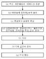
도 1은 본 발명에 의한 탄소 발열체의 제조순서를 나타낸 도면.BRIEF DESCRIPTION OF THE DRAWINGS Fig. 1 is a view showing a manufacturing procedure of a carbon heating element according to the present invention. Fig.
이하, 본 발명을 상세히 설명한다.Hereinafter, the present invention will be described in detail.
본 발명은 종래의 탄소 발열체의 단점을 해소하기 위한 것으로, 높은 도전성을 위하여, 전도성 물질로서 흑연만을 사용하는 것이 아닌, 기타의 비금속 전도성 물질과 금속을 함께 사용하는 것을 특징으로 한다.The present invention is to solve the disadvantages of the conventional carbon heating element and, in order to achieve high conductivity, the present invention is characterized not only by using graphite as a conductive material but also by using a non-metallic conductive material and a metal together.
더욱 구체적으로는, 본 발명에 따른 탄소 발열 조성물은 흑연, 염화제2주석(SnCl4), 삼염화안티몬(SbCl3), 염화비스무트(BiCl3), 몰리브덴(Mo), 알루미늄(Al), 아세트산(acetic acid) 및 계면활성제를 포함하는 것이다.More specifically, the carbon heating composition according to the present invention can be produced by mixing graphite, tin chloride (SnCl4 ), antimony trichloride (SbCl3 ), bismuth chloride (BiCl3 ), molybdenum (Mo), aluminum (Al) acetic acid and a surfactant.
상기와 같이 구성된 탄소 발열 조성물은, 단위면적에 대한 전기저항 특성, 원적외선의 방사율, 화학적 안정성 등을 고려하여 조성한 것으로, 높은 전도성을 가지는 것은 물론, 탄소 발열층을 박막으로 형성할 수 있으며, 내구성 역시 우수한 특성을 갖는다.The carbon heating composition having the above-described structure is formed in consideration of the electric resistance of the unit area, the emissivity of the far-infrared ray, the chemical stability, etc. The carbon heating layer has high conductivity and can be formed into a thin film, And has excellent characteristics.
먼저, 상기 흑연은 본 발명에 따른 탄소 발열 조성물의 기초성분으로서, 앞서 설명된 바와 같이, 도전성이 우수하고, 환경적으로 안전하며, 저렴한 재료이다. 따라서, 이러한 흑연을 탄소 발열 조성물의 기초성분으로 이용하면 우수한 도전성, 가격경쟁력 등을 확보할 수 있는 것이다. 이때, 상기 흑연은 볼 밀링(ball milling)에 의해 분쇄된 나노 입자를 이용함이 바람직한데, 이는 발열체, 즉 발열층의 형성시 나노 기상 증착법을 이용하기 위한 것은 물론, 전도성을 더욱 높이기 위함이다. 상기 볼 밀링의 방법은 이 기술이 속하는 분야에서 공지된 방법을 이용하면 족하며, 그 입자 크기는 2~3000㎚임이 바람직하다.First, the graphite is a basic component of the carbon heating composition according to the present invention, and as described above, is excellent in conductivity, environmentally safe, and inexpensive. Therefore, when such graphite is used as a base component of a carbon heating composition, excellent conductivity and price competitiveness can be ensured. At this time, it is preferable to use the nanoparticles pulverized by ball milling. In order to increase the conductivity, the nano-sized vapor deposition method is used to form a heating element, that is, a heating layer. The ball milling method may use a method well known in the art, and preferably has a particle size of 2 to 3000 nm.
상기 흑연은 용매를 제외한 탄소 발열 조성물 100중량%를 기준으로, 25~35중량%로 포함될 수 있는데, 그 함량이 25중량% 미만이면 도전성이 좋지 못하고, 35중량%를 초과하면 분산성이 저하되는 단점이 있기 때문이다.The graphite may be contained in an amount of 25 to 35% by weight based on 100% by weight of the carbon heating composition excluding the solvent. When the content is less than 25% by weight, the conductivity is poor. When the content is more than 35% by weight, This is because there are disadvantages.
다음으로, 비금속 전도성 물질 중 하나인 염화제2주석(SnCl4) 역시 본 발명의 조성물을 구성하는 기초성분으로, 발열층에 우수한 도전성을 부여하여 발열체가 고온으로 발열할 수 있게 해준다.Next, stannic chloride (SnCl4 ), which is one of the non-metallic conductive materials, is also a basic component constituting the composition of the present invention, and imparts excellent conductivity to the exothermic layer so that the exothermic body can generate heat at a high temperature.
상기 염화제2주석은 용매를 제외한 탄소 발열 조성물 전체 100중량%를 기준으로, 15~25중량%로 포함될 수 있는데, 그 함량이 15중량% 미만이면 도전성이 좋지 못하고, 25중량%를 초과하면 발열층의 안정성이 떨어지기 때문이다.The stannic chloride may be contained in an amount of 15 to 25% by weight based on 100% by weight of the entire carbon heating composition excluding the solvent. When the content is less than 15% by weight, the conductivity is poor. When the content is more than 25% by weight, The stability of the system is deteriorated.
또한, 상기 삼염화안티몬(SbCl3) 역시 발열층에 우수한 도전성을 부여하는 성분으로, 용매를 제외한 탄소 발열 조성물 전체 100중량%를 기준으로, 2~4중량%로 포함될 수 있다. 이는 그 함량이 2중량% 미만이거나, 4중량%를 초과하면, 발열층의 균일성이 떨어져 저항이 불균일해지기 때문이다.The antimony trichloride (SbCl3 ) is also a component that imparts excellent conductivity to the exothermic layer, and may be contained in an amount of 2 to 4% by weight based on 100% by weight of the total exothermic composition excluding the solvent. If the content is less than 2% by weight or more than 4% by weight, the uniformity of the heating layer becomes uneven and the resistance becomes uneven.
상기 염화비스무트(BiCl3) 역시 발열층 내 도전성을 부여하는 것은 물론, 발열층의 내구성, 열안정성을 개선한다. 상기 염화비스무트는 용매를 제외한 탄소 발열 조성물 전체 100중량%를 기준으로, 0.5~1.5중량%로 포함될 수 있는데, 그 함량이 0.5중량% 미만이면 그 효과가 미미하고, 1.5중량%를 초과하면 오히려 발열층의 내구성이 저하되기 때문이다.The bismuth chloride (BiCl3 ) not only imparts conductivity in the exothermic layer, but also improves the durability and thermal stability of the exothermic layer. The bismuth chloride may be contained in an amount of 0.5 to 1.5% by weight based on 100% by weight of the entire carbon heating composition excluding the solvent. If the content is less than 0.5% by weight, the effect is insignificant. If the content is more than 1.5% by weight, The durability of the layer is lowered.
상기 몰리브덴(Mo), 알루미늄(Al) 및 게르마늄(Ge)은 도전성을 부여하기 위한 금속 성분으로서, 상기 몰리브덴, 알루미늄, 게르마늄이 흑연 및 기타의 비금속 전도성 물질과 함께 결정체를 이뤄 발열층, 즉 박막을 형성한다. 이 경우, 흑연 또는 기타의 비금속 성분만으로 발열층을 구성할 때와는 비교할 수 없을 정도의 현저히 우수한 도전성을 갖게 한다. 또한, 상기 게르마늄은 발열시 다량의 원적외선을 방사하므로, 전열기 및 농업용 온풍기, 건조기에 적용시 인체 및 농산물에 유익한 효과를 가져올 수 있다.The molybdenum (Mo), aluminum (Al) and germanium (Ge) are metal components for imparting conductivity, and the molybdenum, aluminum and germanium are crystallized together with graphite and other nonmetal conductive materials to form a heating layer, . In this case, the graphite or other non-metal component alone has remarkably excellent conductivity that is comparable to that of the heat generating layer. In addition, since germanium emits a large amount of far-infrared rays when it generates heat, it can have a beneficial effect on human bodies and agricultural products when applied to electric heaters, hot air fans for agriculture, and dryers.
여기서, 상기 몰리브덴, 알루미늄, 게르마늄은 용매를 제외한 탄소 발열 조성물 전체 100중량%를 기준으로, 몰리브덴 0.5~1.5중량%, 알루미늄 1~3중량%, 게르마늄 2~4중량%로 포함될 수 있는데, 각각의 함량이 기준치 미만이면 도전성 향상의 효과가 떨어지고, 각각의 함량이 기준치를 초과하면 전체적인 제조비용이 상승하는 단점이 있기 때문이다.The molybdenum, aluminum, and germanium may be contained in an amount of 0.5 to 1.5% by weight of molybdenum, 1 to 3% by weight of aluminum, and 2 to 4% by weight of germanium based on 100% by weight of the entire carbon heating composition except for the solvent. If the content is less than the reference value, the effect of improving the conductivity is deteriorated, and if the content exceeds the reference value, the overall manufacturing cost increases.
상기 아세트산(acetic acid)은 조성물을 안정화시키며, 발열층을 박막으로 성형가능하게 하는 동시에, 그 내구성을 개선한다.The acetic acid stabilizes the composition, enables the exothermic layer to be formed into a thin film, and improves its durability.
상기 아세트산은 용매를 제외한 탄소 발열 조성물 전체 100중량%를 기준으로, 7~13중량%로 포함될 수 있는데, 그 함량이 너무 적으면 상기한 효과가 미미하게 되고, 과량이 되면 도전성에 좋지 않은 영향을 미치기 때문이다.The acetic acid may be contained in an amount of 7 to 13% by weight based on 100% by weight of the entire carbon heating composition excluding the solvent. If the content is too small, the effect is insignificant, and if it is excessive, It is because it is crazy.
그리고 상기 계면활성제는 흑연의 분산성 향상을 위한 것으로, 당업계에 공지된 다양한 비이온성, 양이온성, 음이온성 계면활성제를 이용할 수 있다. 상기 계면활성제의 일례로서 실리콘글리콜공중합체를 이용할 수 있다.The surfactant is used for improving the dispersibility of graphite, and various nonionic, cationic, and anionic surfactants known in the art can be used. As an example of the surfactant, a silicone glycol copolymer can be used.
이러한 계면활성제는 용매를 제외한 탄소 발열 조성물 전체 100중량%를 기준으로, 25~35중량%로 포함될 수 있다.Such a surfactant may be contained in an amount of 25 to 35% by weight based on 100% by weight of the entire carbon heating composition excluding the solvent.
아울러, 상기와 같은 성분을 포함하는 본 발명에 따른 탄소 발열 조성물은 용매를 더 포함할 수 있는데, 바람직하게는 용매로서 에탄올을 사용하는 것이다.In addition, the carbon heating composition according to the present invention containing the above-mentioned components may further include a solvent, and preferably ethanol is used as a solvent.
그리고 상기 용매는 앞선 조성물, 즉 용매를 제외한 탄소 발열 조성물에 대하여 0.8~1.2중량비 정도로 포함할 수 있으나, 이를 반드시 제한하는 것은 아니다. 이는 상기 용매는 발열체의 제조시 휘발되는 성분이므로, 전체적인 도전성 및 내구성 등의 물성에 영향을 미치지 않기 때문이다.The solvent may include, but is not limited to, about 0.8 to 1.2 parts by weight of the above composition, that is, the carbon heating composition excluding the solvent. This is because the solvent is a component which is volatilized during the production of the heating element, and thus does not affect the physical properties such as overall conductivity and durability.
상기와 같이 구성되는 탄소 발열 조성물은 전도성 물질로서 탄소 소재인 흑연뿐 아니라, 삼염화안티몬, 염화비스무트 등의 비금속성 전도성 물질, 몰리브덴, 알루미늄, 게르마늄 등의 금속 물질 함께 포함함으로써, 종래 탄소 소재 또는 탄소 소재를 제외한 비금속성 전도성 물질만을 단독으로 사용한 예에 비해 현저히 우수한 전도성을 가지는 것은 물론, 내구성 또한 우수하다.The carbon heating composition having the above-described constitution can be used as a conductive material not only of graphite, which is a carbon material but also a non-metallic conductive material such as antimony trichloride or bismuth chloride, or a metallic material such as molybdenum, aluminum, or germanium, Is superior in durability as well as having remarkably excellent conductivity as compared with the case of using only the non-metallic conductive material except for the conductive material.
이하, 본 발명에 따른 탄소 발열체의 제조방법에 대해 설명한다. 하기 발열체의 설명에 있어서, 앞선 탄소 발열 조성물과 중복되는 내용은 그 설명을 생략한다.Hereinafter, a method for manufacturing a carbon heating element according to the present invention will be described. In the following description of the heating elements, the description overlapping with the preceding carbon heating composition is omitted.
먼저, 본 발명의 탄소 발열체는 기재의 표면에 박막 형태의 발열층이 형성된 것으로, 상기 발열층은 앞서 설명된 탄소 발열 조성물에 의해 증착 형성된 것이다.First, the carbon heating element of the present invention is formed with a heating layer in the form of a thin film on the surface of a substrate, and the heating layer is formed by vapor deposition using the carbon heating composition described above.
이때, 상기 기재로는 유리, 석영은 물론, 이를 제외한 재질의 것일 수 있으며, 그 형태 역시 판형, 고리형 등 다양한 형상일 수 있는바, 기재의 종류, 형상 등을 제한하지 않는다.At this time, the substrate may be glass, quartz, or any other material except the glass, quartz, and the form thereof may be various shapes such as a plate shape, a ring shape, and the like.
아울러, 제조된 탄소 발열체는 고온이나 온열이 필요한 각종 난방용, 급탕용, 건조용, 식품조리용 등 다양한 기기에 적용될 수 있는 것으로, 그 발열체가 사용되는 기기라면 그 종류를 제한하지 않는다.In addition, the produced carbon heating element can be applied to various heating, hot water, drying, food cooking, etc. requiring high temperature or high temperature, and the type of the heating element is not limited as long as the heating element is used.
이러한 본 발명에 따른 탄소 발열체의 제조방법은, (a) 흑연, 계면활성제 및 아세트산을 혼합하는 단계와, (b) 에탄올에 염화제2주석을 용해하는 단계와, (c) 상기 (a) 단계의 혼합물과 상기 (b) 단계의 용해액을 혼합하는 단계와, (d) 상기 (c) 단계의 혼합물에 삼염화안티몬, 염화비스무트, 몰리브덴, 알루미늄 및 게르마늄을 투입하여 교반, 혼합하는 단계와, (e) 상기 (d) 단계의 혼합물을 20~30시간 숙성시켜 탄소 발열 조성물을 제조하는 단계와, (f) 상기 (e) 단계를 통해 제조된 탄소 발열 조성물을 기상 증착법(gas phase evaporation)으로 증발시켜 기재의 표면에 발열층을 증착하는 단계와, (g) 상기 발열층의 양단부에 전극을 형성하는 단계를 포함하는 것을 특징으로 한다.The method for producing a carbon heating material according to the present invention comprises the steps of (a) mixing graphite, a surfactant and acetic acid, (b) dissolving stannic chloride in ethanol, and (c) (B); and (d) adding antimony trichloride, bismuth chloride, molybdenum, aluminum and germanium to the mixture of step (c), stirring and mixing the mixture (e) aging the mixture of step (d) for 20 to 30 hours to produce a carbon heating composition; and (f) evaporating the carbon heating composition prepared in step (e) by gas phase evaporation (G) forming electrodes on both ends of the heat generating layer.
이하, 도 1을 참조하여, 각 단계별로 상세히 설명한다.Hereinafter, each step will be described in detail with reference to FIG.
(a) 흑연, 계면활성제 및 아세트산을 혼합하는 단계.(a) mixing graphite, a surfactant and acetic acid.
먼저, 흑연, 계면활성제 및 아세트산을 각 함량비에 맞도록 측량한 후, 이를 믹서기에 투입하여 약 15~25분간 혼합한다. 이때, 상기 흑연은 볼 밀에 의해 2~3000㎚ 크기의 나노입자로 분쇄된 것을 사용한다.First, graphite, surfactant, and acetic acid are weighed to suit each content ratio, and then mixed in a mixer for about 15 to 25 minutes. At this time, the graphite is pulverized into nanoparticles having a size of 2 to 3000 nm by a ball mill.
(b) 에탄올에 염화제2주석을 용해하는 단계.(b) dissolving stannic chloride in ethanol.
다음으로, 에탄올과 염화제2주석 역시 각 함량비에 맞도록 측량한 후, 에탄올에 상기 염화제2주석을 투입하여 용해한다.Next, the ethanol and the stannic chloride are measured so as to meet the respective content ratios, and then the stannic chloride is added to ethanol to dissolve it.
(c) 상기 (a) 단계의 혼합물과 상기 (b) 단계의 용해액을 혼합하는 단계.(c) mixing the mixture of step (a) and the solution of step (b).
그리고 상기 (b) 단계의 용해액에 상기 (a) 단계의 혼합물을 투입하여 혼합한다. 여기서, 혼합이란 단순히 상기 (b) 단계의 용해액에 상기 (a) 단계의 혼합물을 투입하는 정도면 족하며, 별도의 교반을 할 필요는 없다.The mixture of step (a) is added to the solution of step (b) and mixed. Here, mixing is merely enough to inject the mixture of step (a) into the solution of step (b), and there is no need to perform stirring.
(d) 상기 (c) 단계의 혼합물에 삼염화안티몬, 염화비스무트, 몰리브덴, 알루미늄 및 게르마늄을 투입하여 교반, 혼합하는 단계.(d) adding antimony trichloride, bismuth chloride, molybdenum, aluminum and germanium to the mixture of step (c), stirring and mixing.
다음으로, 삼염화안티몬, 염화비스무트, 몰리브덴, 알루미늄 및 게르마늄을 함량비에 따라 측량한 후, 이를 상기 (c) 단계의 혼합물에 투입한다. 그리고 이를 교반기를 이용하여 약 90~150분간 교반한다. 이때, 상기 교반기의 온도는 45~55℃ 정도가 되도록 하여 그 교반 및 혼합이 충분히 이루어지도록 한다.Next, antimony trichloride, bismuth chloride, molybdenum, aluminum and germanium are weighed according to the content ratio, and then the mixture is added to the mixture of step (c). The mixture is stirred for about 90 to 150 minutes using a stirrer. At this time, the temperature of the stirrer is adjusted to about 45 to 55 ° C so that the stirring and mixing are sufficiently performed.
본 발명에서 각 성분을 상기 (a), (b), (c), (d) 단계로 분리하여 혼합하는 이유는, 각 성분의 혼합의 용이성은 물론, 혼합물의 화학적 안정화를 위한 것이다.In the present invention, the components are separated and mixed in the steps (a), (b), (c) and (d) for the purpose of chemical stability of the mixture as well as easiness of mixing of the respective components.
(e) 상기 (d) 단계의 혼합물을 20~30시간 숙성시켜 탄소 발열 조성물을 제조하는 단계.(e) aging the mixture of step (d) for 20 to 30 hours to prepare a carbon heating composition.
상기와 같이 혼합이 완료되면, 상기 (d) 단계의 혼합물 20~30시간 자연숙성시킴으로써, 탄소 발열 조성물의 제조를 완료한다. 여기서, 상기 자연숙성이란 상기 조성물을 실온 정도(15~30℃)에 방치하는 것이면 족하다.When the mixing is completed as described above, the mixture of step (d) is naturally aged for 20 to 30 hours to complete the production of the carbon heating composition. Here, the natural aging means that the composition is allowed to stand at room temperature (15 to 30 ° C).
(f) 상기 (e) 단계를 통해 제조된 탄소 발열 조성물을 기상 증착법(gas phase evaporation)으로 증발시켜 기재의 표면에 증착하는 단계.(f) evaporating the carbon heating composition prepared in the step (e) by gas phase evaporation to deposit on the surface of the substrate.
그리고 상기 (e) 단계를 통해 제조된 탄소 발열 조성물을 기상 증착법으로 기재의 표면에 증착시켜, 발열층을 형성한다.The carbon heating composition prepared in the step (e) is deposited on the surface of the base material by a vapor deposition method to form a heating layer.
여기서, 상기 기상 증착법으로는 종래의 물리적 기상 증착(physical vapor deposition, PVD)이나 화학적 기상증착(chemical vapor deposition, CVD)과는 다른 나노-기상 증착법을 이용함이 바람직한데, 이러한 나노-기상 증착법을 통해 박막의 발열층을 형성시으로써, 내구성은 물론, 저항치의 균일성 등을 갖도록 한다. As the vapor deposition method, it is preferable to use a nano-vapor deposition method which is different from conventional physical vapor deposition (PVD) or chemical vapor deposition (CVD). Such nano-vapor deposition When a heating layer of a thin film is formed, it has durability as well as uniformity of resistance value.
이를 더욱 구체적으로 설명하면, 상기한 나노-기상 증착법은 주로와 증발대를 포함하는 전기로에서 증착을 하는 것인데, 먼저 기재를 주로의 상부에 고정한다. 그리고 고정된 기재를 500~1000℃ 정도로 20~40분간 예열한다. 이러한 예열은 발열층의 안전한 증착을 위한 것으로, 발열체의 내구성 및 저항의 안정성을 도모할 수 있다.More specifically, in the nano-vapor deposition method, deposition is performed mainly in an electric furnace including an evaporation zone. First, the substrate is fixed to the top of the substrate. The fixed substrate is pre-heated at 500 to 1000 ° C for 20 to 40 minutes. Such preheating is for the safe deposition of the heating layer, and the durability and resistance of the heating element can be stabilized.
다음으로, 전기로 내 증발대에 앞서 제조된 탄소 발열 조성물을 위치시킴으로써, 탄소 발열 조성물을 모두 증발시킨다. 이때, 증발대의 온도는 약 200~300℃ 정도이다. 이 과정에서 용매는 모두 휘발되고, 나머지 성분들만이 기화되는데, 상기 기화된 상태로 분자들이 기재의 표면에 균일하게 증착되는 것이다. 여기서, 상기 증착층, 즉 발열층의 두께는 증발대에 위치시키는 탄소 발열 조성물의 양으로 조절할 수 있는바, 기화된 상태로 분자들이 증착되므로 박막으로의 형성이 가능하며, 균일한 저항을 형성하는 것이다. 따라서, 상기 발열층의 두께는 목적하는 발열량에 따라 조절한다.Next, by placing the carbon heating composition prepared prior to the furnace in the furnace, the carbon heating composition is completely evaporated. At this time, the temperature of the evaporator is about 200 to 300 ° C. In this process, all of the solvent is volatilized and only the remaining components are vaporized, and the molecules are uniformly deposited on the surface of the substrate in the vaporized state. Here, the thickness of the deposition layer, that is, the heating layer can be controlled by the amount of the carbon heating composition to be placed in the evaporation zone. Since the molecules are deposited in a vaporized state, they can be formed into a thin film, will be. Therefore, the thickness of the heating layer is adjusted according to the desired calorific value.
이때, 상기 기재가 판형이 아닌 경우 기재의 회전을 통해 균일한 발열층을 형성시킬 수 있음은 당연하다.At this time, when the substrate is not a plate, it is natural that a uniform heating layer can be formed through rotation of the substrate.
그리고 증착이 완료되면, 증착이 완료된 기재를 약 350~450℃ 정도로 5~15분간 후열을 가하고, 상온에서 서서히 냉각한다.When the deposition is completed, the substrate on which the deposition has been completed is heated at about 350 to 450 DEG C for 5 to 15 minutes, and then slowly cooled at room temperature.
(g) 상기 (f) 단계의 증착층 양단부에 전극을 형성하는 단계.(g) forming electrodes at both ends of the deposition layer in the step (f).
상기 기재에 증착이 완료되면, 상기 증착층, 즉 발열층의 양단부에 전압을 인가하기 위한 전극을 형성한다. 상기 전극은 발열층의 종방향 또는 횡방향으로 적어도 한 쌍 이상씩 형성될 수 있다.When deposition is completed on the substrate, an electrode for applying a voltage to both ends of the deposition layer, that is, the heating layer is formed. The electrodes may be formed in at least one pair in the longitudinal direction or in the transverse direction of the heat generating layer.
상기 전극의 형성의 재료는 제한하지 않는데, 전도성이 우수한 은 분말을 이용한다. 구체적으로는, 은 분말을 송진과 1:0.5~1 부피비 정도로 혼합하여 제조한 전극액을 발열층의 양단부에 도말한다.The material for forming the electrode is not limited, and silver powder having excellent conductivity is used. Specifically, an electrode solution prepared by mixing silver powder at a ratio of 1: 0.5 to 1 volume ratio of rosin is applied to both ends of the heating layer.
그리고 이를 실온(15~30℃)에서 90~210분간 건조한 후, 전기로에 투입하여 약 180~220℃에서 약 100~140분, 750~850℃에서 50~70분간 가열하여 소결한다. 그리고 전기로의 전원을 끄고, 상온 정도가 될 때까지 숙성시킨다.Then, it is dried at room temperature (15 to 30 ° C) for 90 to 210 minutes and then charged into an electric furnace and sintered at about 180 to 220 ° C for about 100 to 140 minutes and at 750 to 850 ° C for 50 to 70 minutes. Turn off the electric furnace, and mature it until it reaches about room temperature.
아울러, 이러한 방법 이외에도 공지된 전극 소재 및 방법을 이용하여 전극을 형성시킬 수 있다.In addition to these methods, electrodes can be formed using known electrode materials and methods.
이와 같이 제조된 탄소 발열체는, 단부에 형성된 전극에 전류를 흘려주면, 발열체에 전류가 흐르면서 발열층이 저항 역할을 하여 열이 발생하게 된다.When a current is supplied to the electrode formed at the end portion of the carbon heating element thus manufactured, current flows through the heating body, and the heating layer acts as a resistance, thereby generating heat.
따라서, 본 발명의 발열체는 단위면적에 대한 전기저항 특성이 우수하여 고온 발열이 가능하고, 균일한 저항치 및 우수한 내구성을 갖는다. 또한, 원적외선을 방사할 뿐 아니라, 에너지 변환 효율이 우수하여 전력을 절감할 수 있으며, 제조공정이 종래와 달리 간단하여 제조단가를 낮출 수 있는 장점이 있다.Therefore, the heat generating element of the present invention is excellent in electric resistance characteristic with respect to a unit area, is capable of high-temperature heat generation, has a uniform resistance value and excellent durability. In addition, it not only radiates far-infrared rays, but also has an excellent energy conversion efficiency, so that power can be saved.
그리고 이러한 장점들로 인해 본 발명에 따른 탄소 발열체는, 히팅(heating) 매트나 패드 등의 침구류, 아파트나 일반주택의 바닥난방 등의 주거용 난방장치, 사무실이나 작업장의 산업용 난방장치, 프린팅 건조 및 도장 건도 등의 각종 산업용 가열장치, 비닐하우스와 축사, 농산물 건조시스템과 같은 농업용 설비, 도로나 주차장의 눈을 녹이는 동결방지장치 등에 적용될 수 있다.In addition, the carbon heating element according to the present invention can be used for heating bedding such as a heating mat or a pad, residential heating such as floor heating of an apartment or a general house, industrial heating of an office or a workplace, Various kinds of industrial heating apparatuses such as a paint condition, a plastic house, a farm house, an agricultural facility such as an agricultural product drying system, and a freeze prevention apparatus for melting snow on a road or parking lot.
이하, 본 발명을 구체적인 실시예를 통해 상세히 설명한다.Hereinafter, the present invention will be described in detail with reference to specific examples.
(실시예들)(Examples)
하기 표 1과 같은 조성을 갖는 발열 조성물을 제조하였다. 그리고 제조된 발열 조성물을 이용하여 200mm×200mm×10mm 크기의 세라믹 판의 일측면에 발열층을 형성하였다. 여기서, 발열층의 형성은 상기 기재를 전기로의 주로에 고정하여 800℃로 30분간 예열하고, 각 발열 조성물 20g을 전기로(주로의 온도 약 700℃)의 증발대(온도 약 230℃)에 위치시켜 모두 증발시켰다. 그리고 상기 전기로의 온도를 약 400℃로 하여 10분간 후열하고, 후열이 끝난 세라믹 판을 상온에서 서서히 냉각시켰다. 그리고 상기 증착된 증착층의 양 끝부분에 전극을 도말한 후, 25℃에서 약 2시간 건조하고, 이를 전극형성로에 투입하여 200℃에서 2시간 가열하고, 800℃에서 1시간 추가 가열한 후, 전극형성로 내에서 상온이 될 때까지 숙성시켰다. 이때, 상기 전극은 은 분말과 송진을 1:1 부피비로 혼합한 전극액을 이용하였다.Exothermic compositions having the compositions shown in Table 1 below were prepared. A heat generating layer was formed on one side of a ceramic plate having a size of 200 mm x 200 mm x 10 mm by using the heat generating composition thus prepared. Here, in order to form the heating layer, the substrate was fixed to the main body of an electric furnace and preheated at 800 DEG C for 30 minutes, and 20 g of each heating composition was placed in an evaporator (temperature of about 230 DEG C) And all were evaporated. The temperature of the electric furnace was set at about 400 DEG C for 10 minutes, and the post-heated ceramic plate was gradually cooled at room temperature. Then, electrodes were coated on both ends of the deposited deposition layer, and then dried at 25 ° C for about 2 hours, put into an electrode forming furnace, heated at 200 ° C for 2 hours, further heated at 800 ° C for 1 hour , And aged until the temperature in the electrode formation furnace reached room temperature. At this time, the electrode was prepared by mixing the silver powder and the rosin in a volume ratio of 1: 1.
(비교예 1)(Comparative Example 1)
실시예 1과 동일하게 실시하되, 흑연을 사용하지 않았다.The same procedure as in Example 1 was carried out except that graphite was not used.
(비교예 2)(Comparative Example 2)
실시예 1과 동일하게 실시하되, 흑연, 몰리브덴, 알루미늄, 게르마늄을 사용하지 않았다.The same procedure as in Example 1 was carried out except that graphite, molybdenum, aluminum, and germanium were not used.
(비교예 3)(Comparative Example 3)
실시예 1과 동일하게 실시하되, 염화제2주석, 삼염화안티몬, 염화비스무트를 사용하지 않았다.The same procedure as in Example 1 was carried out except that stannic chloride, antimony trichloride, and bismuth chloride were not used.
(비교예 4)(Comparative Example 4)
실시예 1과 동일하게 실시하되, 몰리브덴, 알루미늄, 게르마늄을 사용하지 않았다.The same procedure as in Example 1 was carried out except that molybdenum, aluminum, and germanium were not used.
(시험예)(Test Example)
상기 실시예들 및 비교예들의 면저항을 측정하여 그 결과를 하기 표 2에 나타내었다.The sheet resistance values of the above-mentioned Examples and Comparative Examples were measured and the results are shown in Table 2 below.
상기 표 2에서 확인할 수 있는 바와 같이, 실시예 1 내지 4의 면저항이 비교예 1 내지 4보다 현저히 우수함을 확인하였다.As can be seen in Table 2, it was confirmed that the sheet resistance of Examples 1 to 4 was significantly better than that of Comparative Examples 1 to 4.
이상으로 본 발명 내용의 특정 부분을 상세히 기술하였는바, 당업계의 통상의 지식을 가진 자에게 있어서, 이러한 구체적 기술은 단지 바람직한 실시양태일 뿐이며, 이에 의해 본 발명의 범위가 제한되는 것이 아닌 점은 명백할 것이다. 따라서 본 발명의 실질적인 범위는 첨부된 청구항들과 그것들의 등가물에 의하여 정의된다고 할 것이다.It will be apparent to those skilled in the art that various modifications and variations can be made in the present invention without departing from the spirit or scope of the invention. something to do. It is therefore intended that the scope of the invention be defined by the claims appended hereto and their equivalents.
Claims (5)
Translated fromKoreanGraphite, tin chloride (SnCl4 ), antimony trichloride (SbCl3 ), bismuth chloride (BiCl3 ), molybdenum (Mo), aluminum (Al), germanium (Ge), acetic acid and surfactants Wherein the carbon-based exothermic composition is a carbon black.
흑연 25~35중량%, 염화제2주석(SnCl4) 15~25중량%, 삼염화안티몬(SbCl3) 2~4중량%, 염화비스무트(BiCl3) 0.5~1.5중량%, 몰리브덴(Mo) 0.5~1.5중량%, 알루미늄(Al) 1~3중량%, 게르마늄(Ge) 2~4중량%, 아세트산(acetic acid) 7~13중량% 및 계면활성제 25~35중량%를 포함하는 것을 특징으로 하는 탄소 발열 조성물.
The method according to claim 1,
Graphite 25 to 35% by weight chloride of tin (SnCl4) 15 ~ 25 wt%, antimony trichloride (SbCl3) 2 ~ 4 wt% of chloride, bismuth (BiCl3) 0.5 ~ 1.5 wt%, molybdenum (Mo) 0.5 Characterized in that it comprises from 1 to 3% by weight of aluminum (Al), from 2 to 4% by weight of germanium (Ge), from 7 to 13% by weight of acetic acid and from 25 to 35% Carbon heating composition.
용매로서 에탄올을 더 포함하는 것을 특징으로 하는 탄소 발열 조성물.
The method according to claim 1,
Characterized in that it further comprises ethanol as a solvent.
(b) 에탄올에 염화제2주석을 용해하는 단계와,
(c) 상기 (a) 단계의 혼합물과 상기 (b) 단계의 용해액을 혼합하는 단계와,
(d) 상기 (c) 단계의 혼합물에 삼염화안티몬, 염화비스무트, 몰리브덴, 알루미늄 및 게르마늄을 투입하여 교반, 혼합하는 단계와,
(e) 상기 (d) 단계의 혼합물을 20~30시간 숙성시켜 탄소 발열 조성물을 제조하는 단계와,
(f) 상기 (e) 단계를 통해 제조된 탄소 발열 조성물을 기상 증착법(gas phase evaporation)으로 증발시켜 기재의 표면에 증착하는 단계와,
(g) 상기 (f) 단계의 증착층 양단부에 전극을 형성하는 단계를 포함하는 것을 특징으로 하는 탄소 발열체의 제조방법.
(a) mixing graphite, a surfactant and acetic acid,
(b) dissolving stannic chloride in ethanol,
(c) mixing the mixture of step (a) and the solution of step (b)
(d) adding antimony trichloride, bismuth chloride, molybdenum, aluminum and germanium to the mixture of step (c), stirring and mixing the mixture,
(e) aging the mixture of step (d) for 20 to 30 hours to prepare a carbon black exothermic composition;
(f) evaporating the carbonic heating composition prepared in step (e) by gas phase evaporation to deposit on the surface of the substrate,
(g) forming an electrode at both ends of the deposition layer in the step (f).
상기 (f) 단계는,
전기로 내 주로에 기재를 위치시키고,
전기로 내 증발대에 상기 탄소 발열 조성물을 위치시킨 후,
상기 탄소 발열 조성물을 증발시키면서 증기 상태의 상기 탄소 발열 조성물을 기재의 표면에 증착시키는 것임을 특징으로 하는 탄소 발열체의 제조방법.5. The method of claim 4,
The step (f)
Placing the substrate in an electric arc furnace,
Placing the carbonic heating composition in an evaporator in an electric furnace,
Wherein the vaporized carbon heating composition is evaporated on the surface of the substrate while the carbon heating composition is evaporated.
Priority Applications (3)
| Application Number | Priority Date | Filing Date | Title |
|---|---|---|---|
| KR1020160023137AKR101637526B1 (en) | 2016-02-26 | 2016-02-26 | Carbon heating composition and method for menufacturing carbon heating element |
| PCT/KR2017/001141WO2017146391A1 (en) | 2016-02-26 | 2017-02-02 | Carbon heating composition and method for manufacturing carbon heating element using same |
| CN201710093299.3ACN107135557A (en) | 2016-02-26 | 2017-02-21 | Carbon heating composition, the manufacture method of carbon heating body |
Applications Claiming Priority (1)
| Application Number | Priority Date | Filing Date | Title |
|---|---|---|---|
| KR1020160023137AKR101637526B1 (en) | 2016-02-26 | 2016-02-26 | Carbon heating composition and method for menufacturing carbon heating element |
Publications (1)
| Publication Number | Publication Date |
|---|---|
| KR101637526B1true KR101637526B1 (en) | 2016-07-07 |
Family
ID=56500152
Family Applications (1)
| Application Number | Title | Priority Date | Filing Date |
|---|---|---|---|
| KR1020160023137AActiveKR101637526B1 (en) | 2016-02-26 | 2016-02-26 | Carbon heating composition and method for menufacturing carbon heating element |
Country Status (3)
| Country | Link |
|---|---|
| KR (1) | KR101637526B1 (en) |
| CN (1) | CN107135557A (en) |
| WO (1) | WO2017146391A1 (en) |
Cited By (2)
| Publication number | Priority date | Publication date | Assignee | Title |
|---|---|---|---|---|
| KR102279537B1 (en)* | 2020-09-28 | 2021-07-21 | 주식회사 그린머테리얼솔루션 | Composition for transparent thin film heating element |
| KR20220152109A (en)* | 2021-05-07 | 2022-11-15 | 푸지안 징시 뉴 머테리얼 테크놀로지 컴퍼니., 리미티드. | Semiconductor electrothermal film precursor solution and preparation method of semiconductor electrothermal film structure and electrothermal structure |
Citations (4)
| Publication number | Priority date | Publication date | Assignee | Title |
|---|---|---|---|---|
| KR940014694A (en) | 1992-12-29 | 1994-07-19 | 김충세 | Heating coating composition for heating element |
| KR200439456Y1 (en)* | 2006-12-07 | 2008-04-11 | 최성철 | Heating tube |
| KR20100110497A (en)* | 2009-04-03 | 2010-10-13 | 서테크 에이지 | Non-metal heating element composition, method for the preparation of non-metal heating element using the same and non-metal heating element prepared thereby |
| KR101573142B1 (en) | 2014-07-12 | 2015-11-30 | 서울과학기술대학교 산학협력단 | Composition for heating element and heating device fabricated using the composition |
Family Cites Families (5)
| Publication number | Priority date | Publication date | Assignee | Title |
|---|---|---|---|---|
| CN1107492A (en)* | 1994-12-29 | 1995-08-30 | 华中理工大学 | Electric heating high temperature coating |
| CN1671254A (en)* | 2005-02-07 | 2005-09-21 | 杨葆华 | A formulation of semiconductor surface electrothermal coat and making method thereof |
| KR100869179B1 (en)* | 2007-05-16 | 2008-11-18 | 박성돈 | Conductive Thin Film Composition for Thin Film Heating Element |
| KR20090047328A (en)* | 2007-11-07 | 2009-05-12 | 삼성전기주식회사 | Conductive Paste and Printed Circuit Board Using the Same |
| WO2011149127A1 (en)* | 2010-05-27 | 2011-12-01 | 주식회사 자연에너지산업 | Novel non-metallic heat emitter composition, a method for producing a non-metallic heat emitter by using the composition, and a non-metallic heat emitter produced therefrom |
- 2016
- 2016-02-26KRKR1020160023137Apatent/KR101637526B1/enactiveActive
- 2017
- 2017-02-02WOPCT/KR2017/001141patent/WO2017146391A1/ennot_activeCeased
- 2017-02-21CNCN201710093299.3Apatent/CN107135557A/ennot_activeWithdrawn
Patent Citations (4)
| Publication number | Priority date | Publication date | Assignee | Title |
|---|---|---|---|---|
| KR940014694A (en) | 1992-12-29 | 1994-07-19 | 김충세 | Heating coating composition for heating element |
| KR200439456Y1 (en)* | 2006-12-07 | 2008-04-11 | 최성철 | Heating tube |
| KR20100110497A (en)* | 2009-04-03 | 2010-10-13 | 서테크 에이지 | Non-metal heating element composition, method for the preparation of non-metal heating element using the same and non-metal heating element prepared thereby |
| KR101573142B1 (en) | 2014-07-12 | 2015-11-30 | 서울과학기술대학교 산학협력단 | Composition for heating element and heating device fabricated using the composition |
Cited By (3)
| Publication number | Priority date | Publication date | Assignee | Title |
|---|---|---|---|---|
| KR102279537B1 (en)* | 2020-09-28 | 2021-07-21 | 주식회사 그린머테리얼솔루션 | Composition for transparent thin film heating element |
| KR20220152109A (en)* | 2021-05-07 | 2022-11-15 | 푸지안 징시 뉴 머테리얼 테크놀로지 컴퍼니., 리미티드. | Semiconductor electrothermal film precursor solution and preparation method of semiconductor electrothermal film structure and electrothermal structure |
| KR102565781B1 (en) | 2021-05-07 | 2023-08-09 | 푸지안 징시 뉴 머테리얼 테크놀로지 컴퍼니., 리미티드. | Semiconductor electrothermal film precursor solution and preparation method of semiconductor electrothermal film structure and electrothermal structure |
Also Published As
| Publication number | Publication date |
|---|---|
| CN107135557A (en) | 2017-09-05 |
| WO2017146391A1 (en) | 2017-08-31 |
Similar Documents
| Publication | Publication Date | Title |
|---|---|---|
| EP3042540B1 (en) | Electrothermic compositions | |
| KR101737693B1 (en) | Film type heating element with low power comsumption for highly intense heating | |
| AU2018337764B2 (en) | Electrothermic compositions and composites | |
| CN205017608U (en) | Functional membrane ceramic resistor electricity heating element | |
| KR101637526B1 (en) | Carbon heating composition and method for menufacturing carbon heating element | |
| Wang et al. | Bush‐shaped vertical graphene/nichrome wire for blackbody‐like radiative heating | |
| US11706844B2 (en) | Cooktop with a heating coating | |
| Xiao et al. | Polybenzimidazole/conductive carbon black composite driven at low voltage for high-temperature heaters | |
| CN104327554A (en) | Electric heating paint | |
| KR20100110497A (en) | Non-metal heating element composition, method for the preparation of non-metal heating element using the same and non-metal heating element prepared thereby | |
| KR101931254B1 (en) | Planar heater structure containing carbon | |
| CN105916222A (en) | Far infrared electric heating film preparation method | |
| CN103304874B (en) | Flame retardant type PTC polymer heating material and preparation method thereof | |
| KR101419166B1 (en) | Novel non-metallic heat emitter composition, a method for producing a non-metallic heat emitter by using the composition, and a non metallic heat emitter produced there from | |
| CN106304433A (en) | New and effective nanometer heating plate and preparation method thereof | |
| CN109678492A (en) | A kind of Nb2O5Adulterate TiO2Preparation process | |
| CN103781209A (en) | Nano electric heating plate using chemical vapor deposition technology and manufacturing method thereof | |
| CN106576398B (en) | Resistive carbon composites | |
| KR101736203B1 (en) | Polymer thermoelectric material compositions having high electrical conductivity and thermoelectric material film comprising the same | |
| CN102685943A (en) | Efficient energy-saving novel nanometer material electrothermal film | |
| CN106888516A (en) | A kind of Electric radiant Heating Film of nitride oxide doping | |
| KR101551180B1 (en) | Manufacturing method of electrically conductive composition for coating plane heater, and electrically conductive composition for coating plane heater | |
| CN103627241A (en) | Doped graphite electrothermal paint with high-efficient far-infrared emission capacity | |
| KR102126395B1 (en) | coating composition for plane heater and plane heater prepared therefrom | |
| CN113179561A (en) | Graphene-based thermosensitive electrothermal film and forming and curing method |
Legal Events
| Date | Code | Title | Description |
|---|---|---|---|
| PA0109 | Patent application | Patent event code:PA01091R01D Comment text:Patent Application Patent event date:20160226 | |
| PA0201 | Request for examination | ||
| PA0302 | Request for accelerated examination | Patent event date:20160314 Patent event code:PA03022R01D Comment text:Request for Accelerated Examination Patent event date:20160226 Patent event code:PA03021R01I Comment text:Patent Application | |
| E701 | Decision to grant or registration of patent right | ||
| PE0701 | Decision of registration | Patent event code:PE07011S01D Comment text:Decision to Grant Registration Patent event date:20160630 | |
| GRNT | Written decision to grant | ||
| PR0701 | Registration of establishment | Comment text:Registration of Establishment Patent event date:20160701 Patent event code:PR07011E01D | |
| PR1002 | Payment of registration fee | Payment date:20160704 End annual number:3 Start annual number:1 | |
| PG1601 | Publication of registration | ||
| FPAY | Annual fee payment | Payment date:20190528 Year of fee payment:4 | |
| PR1001 | Payment of annual fee | Payment date:20190528 Start annual number:4 End annual number:4 | |
| PR1001 | Payment of annual fee | Payment date:20200427 Start annual number:5 End annual number:5 | |
| PR1001 | Payment of annual fee | Payment date:20210524 Start annual number:6 End annual number:6 | |
| PR1001 | Payment of annual fee | Payment date:20220523 Start annual number:7 End annual number:7 | |
| PR1001 | Payment of annual fee | Payment date:20230522 Start annual number:8 End annual number:8 | |
| PR1001 | Payment of annual fee | Payment date:20250618 Start annual number:10 End annual number:10 |