KR101635892B1 - Head Mount Display Device - Google Patents
Head Mount Display DeviceDownload PDFInfo
- Publication number
- KR101635892B1 KR101635892B1KR1020150141831AKR20150141831AKR101635892B1KR 101635892 B1KR101635892 B1KR 101635892B1KR 1020150141831 AKR1020150141831 AKR 1020150141831AKR 20150141831 AKR20150141831 AKR 20150141831AKR 101635892 B1KR101635892 B1KR 101635892B1
- Authority
- KR
- South Korea
- Prior art keywords
- barrel
- housing
- unit
- head
- delete delete
- Prior art date
- Legal status (The legal status is an assumption and is not a legal conclusion. Google has not performed a legal analysis and makes no representation as to the accuracy of the status listed.)
- Expired - Fee Related
Links
Images


Classifications
- G—PHYSICS
- G02—OPTICS
- G02B—OPTICAL ELEMENTS, SYSTEMS OR APPARATUS
- G02B27/00—Optical systems or apparatus not provided for by any of the groups G02B1/00 - G02B26/00, G02B30/00
- G02B27/01—Head-up displays
- G02B27/017—Head mounted
- G02B27/0172—Head mounted characterised by optical features
- G—PHYSICS
- G02—OPTICS
- G02B—OPTICAL ELEMENTS, SYSTEMS OR APPARATUS
- G02B27/00—Optical systems or apparatus not provided for by any of the groups G02B1/00 - G02B26/00, G02B30/00
- G02B27/01—Head-up displays
- G02B27/017—Head mounted
- G02B27/0176—Head mounted characterised by mechanical features
- G—PHYSICS
- G02—OPTICS
- G02B—OPTICAL ELEMENTS, SYSTEMS OR APPARATUS
- G02B27/00—Optical systems or apparatus not provided for by any of the groups G02B1/00 - G02B26/00, G02B30/00
- G02B27/01—Head-up displays
- G02B27/017—Head mounted
- G02B2027/0178—Eyeglass type
Landscapes
- Physics & Mathematics (AREA)
- General Physics & Mathematics (AREA)
- Optics & Photonics (AREA)
Abstract
Description
Translated fromKorean본 발명은 사용자에 따라 상이한 시력 및 동공 사이의 간격에 맞춰 조정가능한 헤드 마운트 디스플레이 장치에 관한 것이다.The present invention relates to a head-mounted display device adjustable to different visual acuities and pupil spacing according to the user.
다양한 디스플레이 형태가 등장하면서 머리에 장착하여 영상을 감상하는 헤드마운트 타입의 디스플레이 장치가 등장하고 있다. 이러한 장치를 헤드 마운트 디스플레이(HMD: Head Mount Display)라고 칭하며, 헤드 마운트 디스플레이는 눈에 인접하게 위치하기 때문에 초점 조절이 필요하다.A head-mounted type display device has appeared, in which a variety of display forms come into view while attaching to the head to view an image. Such a device is called a head-mounted display (HMD), and the head-mounted display is positioned adjacent to the eye, so focus adjustment is required.
특히, 최근에는 가상현실 헤드 마운트 디스플레이가 등장하면서 2D이미지가 아닌 3D입체영상을 제공하고, 사용자의 움직임에 따라 좌우 360° 파노라마 이미지 뿐만 아니라 상하 방향으로 고개를 돌리면 다양한 이미지를 제공할 수 있다.In particular, in recent years, a virtual reality head mount display has been introduced to provide a 3D stereoscopic image, not a 2D image, and a variety of images can be provided by turning a head 360 ° panoramic image as well as a vertical panoramic image according to a user's movement.
가상현실 헤드 마운트 디스플레이는 주변의 빛을 완전히 차단하고, 좌안과 우안에 각각 다른 영상을 제공하여 3D입체 영상을 제공할 수 있다. 사용자가 2개의 이미지(좌안 이미지, 우안 이미지)가 하나의 입체 이미지로 인식하기 위해서는 초점 거리를 잘 맞춰야 한다.The virtual reality head-mounted display is able to provide 3D stereoscopic images by completely blocking ambient light and providing different images to the left and right eyes. In order for a user to recognize two images (a left-eye image and a right-eye image) as one stereoscopic image, the focal distance must be set to a proper value.
정확한 초점거리를 맞추기 위해 모터 등의 장치가 헤드 마운트 디스플레이에 구비되면 착용감이 저하되기 때문에 보다 간단한 구조의 초점거리 조절 장치가 필요하다.When a device such as a motor is provided on the head mount display to adjust an accurate focal distance, the fitting feeling is reduced, and therefore, a focal length adjusting device with a simple structure is needed.
헤드 마운트 디스플레이 장치는 안경을 벗고 착용하기 때문에 시력이 나쁘면 정확한 영상을 볼 수 없고 렌즈를 착용했을 때와 렌즈를 착용하지 않았을 때 시력이 변화한다. 즉, 사용자의에 따라 다른 초점거리를 맞출 수 있어야 하고 더 나아가 동일사용자가 사용하는 경우라도 렌즈 착용여부에 따라 초점거리를 재설정해야하는 문제가 있다. 또한, 사용자에 따라 눈의 간격이 차이가 있어 사용자에 따라 3D영상이 선명하게 나타나지 않고 어지럼증을 유발시킬 수 있다.The head-mounted display unit wears off glasses, so if the visual acuity is bad, it can not see the correct image, and the visual acuity changes when the lens is worn and when the lens is not worn. That is, it is necessary to be able to adjust a different focal distance according to the user, and furthermore, there is a problem that the focal distance must be reset depending on whether the lens is worn by the same user. In addition, since there is a difference in eye interval according to the user, the 3D image may not be displayed clearly according to the user and may cause dizziness.
본 발명은 초점거리조정부 및 한 쌍의 렌즈 사이의 거리와 동공 사이 간격에 일치시키는 수평조정부를 포함하는 헤드 마운트 디스플레이 장치를 제공하는 것을 목적으로 한다.It is an object of the present invention to provide a head-mounted display device including a focal length adjusting section and a horizontal adjusting section which coincides with a distance between a pair of lenses and an interval between pupils.
전면은 차폐되고 배면은 개구부를 포함하는 하우징; 좌우로 배치된 한 쌍의 시각모듈(optic module); 및 상기 하우징을 사용자의 머리에 고정하는 헤드 고정부를 포함하며, 상기 시각모듈은, 상기 하우징 내부에 위치하는 디스플레이부; 일측은 상기 하우징 내부에 위치하고 타측은 상기 개구부를 통해 상기 하우징 외측으로 노출되는 배럴; 상기 배럴에 고정된 렌즈; 상기 배럴과 상기 디스플레이부 사이의 거리를 조정하는 초점조정부 및 상기 한 쌍의 시각모듈의 수평방향 이동을 가이드 하는 수평조정부를 구비하고, 상기 초점조정부와 상기 수평조정부는 다른 시각모듈의 초점조정부 및 수평조정부와 독립적으로 조작가능한 헤드 마운트 디스플레이 장치를 제공한다.A housing having a front surface shielded and a rear surface including an opening; A pair of left and right optic modules; And a head fixing part fixing the housing to a user's head, wherein the visual module comprises: a display part located inside the housing; A barrel having one side positioned within the housing and the other side exposed to the outside of the housing through the opening; A lens fixed to the barrel; And a horizontal adjustment unit for guiding the horizontal movement of the pair of vision modules. The focus adjustment unit and the horizontal adjustment unit adjust the focus adjustment unit and the horizontal adjustment unit of the time module, A head-mounted display device that can be operated independently of an adjustment unit.
상기 시각모듈은, 상기 디스플레이부의 배면에 결합하고 상기 배럴의 일측 둘레를 감싸는 배럴 수용부를 포함하는 디스플레이 프레임을 더 포함하고, 상기 초점조정부는 상기 배럴 수용부 내의 상기 배럴의 위치를 변경할 수 있다.The visual module may further include a display frame including a barrel accommodating portion coupled to a back surface of the display portion and surrounding one side of the barrel, and the focus adjusting portion may change a position of the barrel in the barrel accommodating portion.
상기 초점조정부는, 상기 배럴의 일측 둘레에 형성된 나사산; 및 상기 배럴 수용부 내측에 상기 나사산에 상응하여 형성된 나사홈을 포함할 수 있다.Wherein the focus adjustment unit includes: a screw thread formed around one side of the barrel; And a screw groove formed inside the barrel accommodating portion corresponding to the screw thread.
상기 배럴의 타측 둘레에 형성된 마찰홈을 더 포함할 수 있다.And a friction groove formed on the other side of the barrel.
상기 수평조정부는 상기 시각모듈에 형성되며 고정홀을 포함하는 체결부; 및 상기 고정홀을 관통하며 좌우방향으로 연장되며 상기 하우징에 양단이 고정된 슬라이드 샤프트을 포함하며, 상기 시각모듈을 사용자가 좌우방향으로 이동시 상기 체결부는 상기 슬라이드 샤프트을 따라 이동할 수 있다.Wherein the horizontal adjustment unit comprises: a fastening part formed on the visual module and including a fixing hole; And a slide shaft extending in the left-right direction through the fixing hole and having both ends fixed to the housing. When the user moves the visual module in the left-right direction, the coupling portion can move along the slide shaft.
상기 체결부는 상기 시각모듈의 상부에 위치하는 제1 체결부와 상기 시각모듈의 상부에 위치하는 제2 체결부를 포함하고, 상기 제1 체결부에 형성된 제1 고정홀은 상기 슬라이드 샤프트의 단면 크기에 상응하며, 상기 제2 체결부에 형성된 제2 고정홀은 상기 슬라이드 샤프트의 단면 크기보다 상하방향으로 더 길게 형성할 수 있다.Wherein the fastening portion includes a first fastening portion located at an upper portion of the time module and a second fastening portion located at an upper portion of the time module, and the first fastening hole formed in the first fastening portion is a cross- And the second fixing hole formed in the second fastening portion may be longer in the vertical direction than the sectional size of the slide shaft.
상기 체결부는 상기 슬라이드 샤프트과 접촉마찰을 증대시키는 마찰부재를 더 포함할 수 있다.The fastening portion may further include a friction member for increasing contact friction with the slide shaft.
상기 하우징에 형성된 개구부는, 상기 배럴의 크기보다 좌우방향으로 더 길게 형성할 수 있다.The opening formed in the housing may be longer in the lateral direction than the size of the barrel.
본 발명의 다른 측면에 따르면 전면은 차폐되고 배면은 개구부를 포함하는 하우징; 좌우로 배치된 한 쌍의 시각모듈(optic module); 상기 한 쌍의 시각모듈 사이에 위치하며, 영상신호를 외부로부터 수신하여 상기 디스플레이부에 제공하는 메인기판; 및 상기 하우징을 사용자의 머리에 고정하는 헤드 고정부를 포함하며,According to another aspect of the present invention, there is provided a display device comprising: a housing having a front surface shielded and a rear surface including an opening; A pair of left and right optic modules; A main board positioned between the pair of visual modules, for receiving a video signal from the outside and providing the video signal to the display unit; And a head fixing portion for fixing the housing to a user's head,
상기 시각모듈은, 상기 하우징 내부에 위치하는 디스플레이부; 상기 디스플레이부의 일단에 결합하고, 상기 메인기판으로 부터 신호를 수신하여 상기 디스플레이부의 픽셀별로 제어하는 디스플레이 구동부; 상기 메인기판과 상기 디스플레이부 사이를 연결하는 연결부; 일측은 상기 하우징 내부에 위치하고 타측은 상기 개구부를 통해 상기 하우징 외측으로 노출되는 배럴; 및 상기 배럴에 고정된 렌즈를 구비한 헤드 마운트 디스플레이 장치를 제공한다.The time module includes: a display unit located inside the housing; A display driver coupled to one end of the display unit and configured to receive signals from the main substrate and to control signals for each pixel of the display unit; A connection part connecting the main board and the display part; A barrel having one side positioned within the housing and the other side exposed to the outside of the housing through the opening; And a lens fixed to the barrel.
디스플레이 구동부상기 좌측 시각모듈의 디스플레이 구동부와 우측 시각모듈의 디스플레이 구동부는 좌우 대칭구조를 가질 수 있다.Display Driver The display driver of the left time module and the display driver of the right time module may have a symmetrical structure.
상기 연결부는 상기 메인기판의 상하 방향의 중간에 위치할 수 있다.The connecting portion may be located in the middle of the main board in the vertical direction.
상기 연결부는 플렉서블한 재질을 포함할 수 있다.The connection portion may include a flexible material.
상기 하우징의 일측 또는 상기 헤드 고정부에 형성되어 외부장치와 연결하는 인터페이스부; 및 상기 인터페이스부와 상기 메인기판을 연결하는 플렉서블 기판을 더 포함할 수 있다.An interface formed on one side of the housing or the head fixing part and connected to an external device; And a flexible substrate connecting the interface unit and the main substrate.
외부 단말기와 무선통신 방식으로 영상데이터 및 음향 데이터를 전송받는 무선통신부를 더 포함할 수 있다.And a wireless communication unit for receiving image data and sound data in a wireless communication manner with an external terminal.
상기 헤드 고정부는, 상기 하우징의 좌우 양측에 각각 결합하여 사용자의 귀에 거는 안경다리부를 더 포함할 수 있다.The head fixing unit may further include a pair of glasses legs coupled to the left and right sides of the housing to hang on the user's ear.
상기 안경다리부의 내측에 위치하는 쿠션부를 더 포함할 수 있다.And a cushion portion located inside the eyeglass leg portion.
상기 하우징과 사용자의 얼굴 사이에 위치하며 외부 빛을 차단하는 후드부를 더 포함할 수 있다.And a hood unit positioned between the housing and the face of the user for blocking external light.
상기 하우징의 배면 방향 중앙에 위치하는 근접센서를 더 포함하며 상기 제어부는 상기 근접센서에서 근접한 물체를 감지하면 상기 디스플레이부의 화면을 활성화할 수 있다.The proximity sensor may further include a proximity sensor located at the center of the backside of the housing, and the control unit may activate a screen of the display unit when the proximity sensor senses a nearby object.
상기 하우징의 방향의 변화를 감지하는 자이로 센서; 상기 하우징 외측으로 노출된 홀드 버튼; 및 상기 자이로 센서에서 감지한 방향에 따라 상기 디스플레이부에서 출력되는 영상이 변화하도록 상기 디스플레이부를 제어하고, 상기 홀드 버튼에서 홀드신호가 생성되면 상기 디스플레이부에서 출력되는 영상이 상기 하우징의 방향이 변화하더라도 변화하지 않도록 상기 디스플레이부를 제어하는 메인기판을 더 포함할 수 있다.A gyro sensor for sensing a change in the direction of the housing; A hold button exposed to the outside of the housing; And controlling the display unit such that an image output from the display unit changes according to a direction sensed by the gyro sensor. When a hold signal is generated in the hold button, an image outputted from the display unit changes in a direction of the housing And a main board for controlling the display unit so as not to be changed.
상기 한 쌍의 시각모듈 사이에서 돌출되어 사용자의 코에 안착되는 코패드를 더 포함하며, 상기 코패드는 사용자의 코의 측면과 상면을 감싸는 V자 형상으로 형성할 수 있다.And a nose pad protruded between the pair of visual modules and seated on the nose of the user, wherein the nose pad is formed in a V-shape surrounding the side and upper surface of the nose of the user.
본 발명의 적어도 일 실시예에 따르면 사용자의 시력에 맞춰 초점거리를 조정할 수 있고, 한 쌍의 렌즈 사이의 거리와 동공 사이 간격에 일치시키는 수평조정부를 포함하여 보다 편안하게 3D영상을 감상할 수 있다.According to at least one embodiment of the present invention, the focal distance can be adjusted according to the visual acuity of the user, and a horizontal adjustment unit that matches the distance between the pair of lenses and the interval between the pupils can be more comfortably appreciated .
특히 본원 발명은 좌안의 시각모듈과 우안의 시각모듈을 각각 독립적으로 제어 가능하여 사용자별로 차이가 있는 좌안시력과 우안시력에 따라 조절할 수 있고, 눈과 코의 거리가 상이한 것을 미세하게 조정할 수 있다.In particular, the present invention can control the left and right eye modules independently of the left eye and right eye, respectively, and can adjust the distances between the eyes and the nose to be finely adjusted.
본 발명의 적용 가능성의 추가적인 범위는 이하의 상세한 설명으로부터 명백해질 것이다. 그러나 본 발명의 사상 및 범위 내에서 다양한 변경 및 수정은 당업자에게 명확하게 이해될 수 있으므로, 상세한 설명 및 본 발명의 바람직한 실시 예와 같은 특정 실시 예는 단지 예시로 주어진 것으로 이해되어야 한다.Further scope of applicability of the present invention will become apparent from the following detailed description. It should be understood, however, that the detailed description and specific examples, such as the preferred embodiments of the invention, are given by way of illustration only, since various changes and modifications within the spirit and scope of the invention will become apparent to those skilled in the art.
도 1은 본 발명의 헤드 마운트 디스플레이 장치의 블럭도이다.
도 2 및 도 3은 본 발명의 헤드 마운트 디스플레이 장치를 다른 측면에서 바라본 사시도이다.
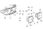
도 4는 본 발명의 헤드 마운트 디스플레이 장치의 분해 사시도이다.
도 5는 본 발명의 헤드 마운트 디스플레이 장치의 착용 상태를 도시한 도면이다.
도 6은 본 발명의 헤드 마운트 디스플레이 장치의 초점조절 방법을 도시한 도면이다.
도 7은 본 발명의 헤드 마운트 디스플레이 장치의 초점조절 원리를 도시한 도면이다.
도 8은 본 발명의 헤드 마운트 디스플레이 장치의 시각모듈, 하우징 및 수평조정부를 도시한 분해 사시도이다.
도 9 및 도 10은 본 발명의 헤드 마운트 디스플레이 장치의 수평조정부의 동작을 설명하기 위한 도면이다.
도 11은 본 발명의 헤드 마운트 디스플레이 장치의 수평조정부를 측방향에서 바라본 도면이다.
도 12는 본 발명의 헤드 마운트 디스플레이 장치의 디스플레이부와 메인기판의 연결상태를 도시한 도면이다.1 is a block diagram of a head-mounted display device of the present invention.
Figs. 2 and 3 are perspective views of the head-mounted display device of the present invention viewed from the other side.
4 is an exploded perspective view of the head-mounted display device of the present invention.
5 is a view showing the wearing state of the head-mounted display device of the present invention.
6 is a view showing a focus adjustment method of the head-mounted display device of the present invention.
7 is a view showing the principle of focus adjustment of the head-mounted display device of the present invention.
8 is an exploded perspective view showing a visual module, a housing, and a horizontal adjustment unit of the head-mounted display device of the present invention.
9 and 10 are views for explaining the operation of the horizontal adjustment unit of the head-mounted display device of the present invention.
11 is a side view of the horizontal adjustment portion of the head-mounted display device of the present invention.
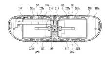
12 is a view illustrating a connection state between a display unit and a main board of the head-mounted display device of the present invention.
이하, 첨부된 도면을 참조하여 본 명세서에 개시된 실시 예를 상세히 설명하되, 도면 부호에 관계없이 동일하거나 유사한 구성요소는 동일한 참조 번호를 부여하고 이에 대한 중복되는 설명은 생략하기로 한다. 이하의 설명에서 사용되는 구성요소에 대한 접미사 "모듈" 및 "부"는 명세서 작성의 용이함만이 고려되어 부여되거나 혼용되는 것으로서, 그 자체로 서로 구별되는 의미 또는 역할을 갖는 것은 아니다. 또한, 본 명세서에 개시된 실시 예를 설명함에 있어서 관련된 공지 기술에 대한 구체적인 설명이 본 명세서에 개시된 실시 예의 요지를 흐릴 수 있다고 판단되는 경우 그 상세한 설명을 생략한다. 또한, 첨부된 도면은 본 명세서에 개시된 실시 예를 쉽게 이해할 수 있도록 하기 위한 것일 뿐, 첨부된 도면에 의해 본 명세서에 개시된 기술적 사상이 제한되지 않으며, 본 발명의 사상 및 기술 범위에 포함되는 모든 변경, 균등물 내지 대체물을 포함하는 것으로 이해되어야 한다.Hereinafter, embodiments of the present invention will be described in detail with reference to the accompanying drawings, wherein like reference numerals are used to designate identical or similar elements, and redundant description thereof will be omitted. The suffix "module" and " part "for the components used in the following description are given or mixed in consideration of ease of specification, and do not have their own meaning or role. In the following description of the embodiments of the present invention, a detailed description of related arts will be omitted when it is determined that the gist of the embodiments disclosed herein may be blurred. It is to be understood that both the foregoing general description and the following detailed description are exemplary and explanatory and are intended to provide further explanation of the invention as claimed. , ≪ / RTI > equivalents, and alternatives.
제1, 제2 등과 같이 서수를 포함하는 용어는 다양한 구성요소들을 설명하는데 사용될 수 있지만, 상기 구성요소들은 상기 용어들에 의해 한정되지는 않는다. 상기 용어들은 하나의 구성요소를 다른 구성요소로부터 구별하는 목적으로만 사용된다.Terms including ordinals, such as first, second, etc., may be used to describe various elements, but the elements are not limited to these terms. The terms are used only for the purpose of distinguishing one component from another.
어떤 구성요소가 다른 구성요소에 "연결되어" 있다거나 "접속되어" 있다고 언급된 때에는, 그 다른 구성요소에 직접적으로 연결되어 있거나 또는 접속되어 있을 수도 있지만, 중간에 다른 구성요소가 존재할 수도 있다고 이해되어야 할 것이다. 반면에, 어떤 구성요소가 다른 구성요소에 "직접 연결되어" 있다거나 "직접 접속되어" 있다고 언급된 때에는, 중간에 다른 구성요소가 존재하지 않는 것으로 이해되어야 할 것이다.It is to be understood that when an element is referred to as being "connected" or "connected" to another element, it may be directly connected or connected to the other element, . On the other hand, when an element is referred to as being "directly connected" or "directly connected" to another element, it should be understood that there are no other elements in between.
단수의 표현은 문맥상 명백하게 다르게 뜻하지 않는 한, 복수의 표현을 포함한다.The singular expressions include plural expressions unless the context clearly dictates otherwise.
본 출원에서, "포함한다" 또는 "가지다" 등의 용어는 명세서상에 기재된 특징, 숫자, 단계, 동작, 구성요소, 부품 또는 이들을 조합한 것이 존재함을 지정하려는 것이지, 하나 또는 그 이상의 다른 특징들이나 숫자, 단계, 동작, 구성요소, 부품 또는 이들을 조합한 것들의 존재 또는 부가 가능성을 미리 배제하지 않는 것으로 이해되어야 한다.In the present application, the terms "comprises", "having", and the like are used to specify that a feature, a number, a step, an operation, an element, a component, But do not preclude the presence or addition of one or more other features, integers, steps, operations, elements, components, or combinations thereof.
도 1은 본 발명의 헤드 마운트 디스플레이 장치(100)의 블럭도를 도시한 도면이다. 본 발명의 헤드 마운트 디스플레이 장치(100)는 디스플레이부(210), 음향출력부(165), 구동부(260), 사용자 입력부(123), 인터페이스부(160), 센싱부(140), 제어부(180) 및 무선통신부(185)를 포함한다.1 is a block diagram of a head-mounted
디스플레이부(210)는 일면의 영상출력부에서 영상 정보를 출력하는 장치로서, 헤드 마운트 디스플레이 장치(100)의 좌안과 우안에 각각 하나씩 구비된다. 디스플레이부(210)는 좌안 또는 우안에 제공하는 영상을 제공하며, 동일한 영상을 제공할 수도 있고, 촬영 각도가 상이한 2개의 영상을 좌안과 우안에 각각 제공하는 경우 3D 입체 영상을 제공할 수 있다.The
디스플레이부(210)는 액정 디스플레이(liquid crystal display, LCD), 박막 트랜지스터 액정 디스플레이(thin film transistor-liquid crystal display, TFT LCD), 유기 발광 다이오드(organic light-emitting diode, OLED), 플렉서블 디스플레이(flexible display), 3차원 디스플레이(3D display), 전자잉크 디스플레이(e-ink display) 중에서 적어도 하나를 포함할 수 있다.The
디스플레이부(210)는 영상 출력부와 사용자의 눈 사이에 위치하여 디스플레이부(210)에서 출력되는 영상의 초점거리를 조정하는 렌즈(250)를 더 포함할 수 있다.The
구동부(260)은 디스플레이부(210)의 위치를 사용자의 좌안과 우안의 동공간격에 맞추어 조정하고, 사용자의 시력에 맞추어 디스플레이부(210)의 전면에 위치하는 렌즈(250)의 위치를 조정하는 역할을 한다. 구동부(260)는 좌안과 우안의 동공 간격을 맞추기 위한 수평조정부(223, 265, 267)와 좌안과 우안 각각의 시력에 따라 렌즈(250)와 디스플레이부(210) 사이의 간격을 조정하는 초점조정부(227, 247)를 포함한다.The driving
음향출력부(165)는 골전도 스피커를 구비하여 사용자의 두개골로 직접 소리를 전달하거나 이어잭을 구비하여 이어폰을 통해 음향을 사용자에게 전달할 수 있다.The
사용자 입력부(123)는 사용자로부터 정보를 입력받기 위한 것으로, 사용자 입력부(123)를 통해 정보가 입력되면, 제어부(180)는 입력된 정보에 대응되도록 이동 단말기(100)의 동작을 제어할 수 있다.The
이러한, 사용자 입력부(123)는 기계식 (mechanical) 입력수단(또는, 메커니컬 키, 예를 들어, 헤드 마운트 디스플레이 장치(100)의 전·후면 또는 측면에 위치하는 버튼, 돔 스위치 (dome switch), 조그 휠, 조그 스위치 등) 및 터치식 입력수단을 포함할 수 있다. 본 실시예의 사용자 입력부(123)는 도 2에 도시된 바와 같이 돔 스위치를 포함하는 버튼형태(123a, 123b)를 이용하여 하우징(110)의 측면에 노출된 형태로 구비할 수 있다.The
인터페이스부(160)는 헤드 마운트 디스플레이 장치(100)를 외부기기와 연결시킬 수 있는 통로가 된다. 예를 들어, 인터페이스부(160)는 외부기기로 부터 영상신호를 제공받거나 전원을 공급받을 수 있다. 얼굴에 거치하는 장치이므로 헤드 마운트 디스플레이 장치(100) 자체에 배터리를 구비하면 무게가 증가하는 문제가 있는 바, 인터페이스부(160)를 통해 외부 전원을 공급받을 수 있다.The
센싱부(140)는 사용자가 헤드 마운트 디스플레이 장치(100)를 착용했는지 여부를 감지하는 근접센서(143, 도 3 참조)를 포함할 수 있다. 근접센서(143)에서 착용을 감지하면 디스플레이부(210)를 활성화 상태로 전환할 수 있다.The
센싱부(140)는 그 외에 터치 센서(touch sensor), 가속도 센서(acceleration sensor), 자기 센서(magnetic sensor), 중력 센서(G-sensor), 자이로스코프 센서(gyroscope sensor), 모션 센서(motion sensor), RGB 센서, 적외선 센서(IR 센서: infrared sensor), 지문인식 센서(finger scan sensor), 초음파 센서(ultrasonic sensor) 등을 구비할 수 있다.The
무선통신부(185)는 외부 단말기와 무선통신을 수행하여 외부 단말기로 부터 영상정보를 수신할 수 있다. 외부 단말기와의 거리가 멀지 않은 상태에서 주로 이용하는 바, 근거리 통신 방식을 이용할 수 있다. 블루투스(Bluetooth™), RFID(Radio Frequency Identification), 적외선 통신(Infrared Data Association; IrDA), UWB(Ultra Wideband), ZigBee, NFC(Near Field Communication), Wi-Fi(Wireless-Fidelity), Wi-Fi Direct, Wireless USB(Wireless Universal Serial Bus) 기술 중 적어도 하나를 이용하여, 근거리 통신을 지원할 수 있다.The
제어부(180)는 상기 디스플레이부(210), 무선통신부, 센싱부(140), 인터페이스부(160) 및 사용자 입력부(123)과 연결되어 헤드 마운트 디스플레이 장치(100)를 제어한다. 제어부(180)는 무선 통신부 또는 인터페이스부(160)를 통해 전송받은 영상데이터를 기초로 디스플레이부(210)에서 영상을 출력하도록 제어한다. 또한 제어부(180)는 센싱부(140)에서 감지한 감지결과를 이용하여 헤드 마운트 디스플레이 장치(100)의 디스플레이부(210)를 활성화 할 수 있다.The
사용자 입력부(123)에서 입력된 사용자 명령 신호에 따라 디스플레이부(210)의 화면을 제어할 수 있다. 이 경우, 필요에 따라서는 상기 인터페이스부(160) 및 상기 무선통신부를 통해 외부 단말기를 제어할 수 있다.The
도 2 및 도 3은 본 발명의 헤드 마운트 디스플레이 장치(100)를 다른 측면에서 바라본 사시도이고, 도 4를 참조하면 본 발명의 헤드 마운트 디스플레이 장치의 분해 사시도로서, 하우징(110), 상기 하우징(110)을 사용자의 머리에 고정하기 위한 헤드 고정부(130), 사용자의 좌안 우안에 각각 영상을 제공하는 한 쌍의 시각모듈(200)을 포함한다.2 and 3 are perspective views of the head-mounted
하우징(110)은 사용자의 눈의 전면에 위치하며, 전면은 평면 또는 곡면 모두 가능하나 배면은 사용자의 얼굴형상에 휘어진 곡면을 포함할 수 있다. 하우징(110)은 고글과 유사한 형상을 가지게 된다. 하우징(110)의 전면은 막혀있고, 배면은 개구부(113)가 형성되며 상기 개구부(113)에 시각모듈(200)이 삽입된다.The
하우징(110)은 각종부품이 실장되고 사용자의 눈 방향에 인접하게 배치되는 제1 케이스, 상기 제1 케이스와 결합하여 하우징(110)의 측면을 형성하는 제2 케이스, 및 하우징(110)의 전면에 위치하는 제3 케이스를 포함할 수 있다. 제2 케이스는 제1 케이스 또는 제3 케이스와 일체형으로 형성될 수 있으며, 본 실시예의 제2 케이스는 제1 케이스를 지지하는 격자형 프레임을 포함하는 것을 특징으로 한다.The
하우징(110)의 제1 케이스, 제2 케이스 및 제3 케이스는 합성수지를 사출하여 형성되거나 금속, 예를 들어 스테인레스 스틸(STS), 알루미늄(Al), 티타늄(Ti) 등으로 형성될 수도 있다. 각 케이스는 동일 재질을 이용할 수도 이종 재질을 이용할 수 있다.The first case, the second case, and the third case of the
제1 케이스에는 한 쌍의 개구부(113)가 형성되며 상기 개구부(113)를 통해 한 쌍의 시각모듈(200)이 노출된다. 하우징(110)을 사용자의 눈의 위치와 맞추어 고정하기 위해 코받침을 더 포함할 수 있다. 일반적인 코받침(116)은 사용자의 코 양쪽을 각각 지지하나, 본 발명의 경우 코에 인가되는 무게를 분산시키기 위해 코의 측면과 상면을 감싸는 V자 형태의 코패드(115)를 더 포함할 수 있다. 코패드(115)는 탄성 부재를 이용하여 코에 부담감을 줄일 수 있다.In the first case, a pair of
상기 하우징(110)을 사용자의 머리에 고정하기 위한 헤드 고정부는 탄성을 갖는 밴드 형태 또는 도 2 및 도 3에 도시된 바와 같이 안경다리부(130)로 이루어질 수 있다. 안경다리부(130)는 강성이 있는 부재로 이루어지기 때문에 힌지(135)를 구비하여 휴대성을 높일 수 있다.The head fixing part for fixing the
안경다리부(130)의 하측에 사용자의 귀가 위치하여 헤드 마운트 디스플레이 장치(100)가 하측 방향으로 흘러내리는 것을 방지한다. 하우징(110)의 무게가 있기 때문에 안경다리부(130)는 사용자의 머리에 단단히 고정되도록 머리 뒤쪽까지 감싸는 형태로 형성할 수 있다. 마찰력을 높이고 착용시 불편함을 줄이기 위해 머리와 맞닿는 내측부에 탄성이 있는 쿠션부(137)를 더 구비할 수 있다.The ears of the user are positioned below the
안경다리부(130)는 탄성이 큰 재질을 이용하여 헤드 마운트 디스플레이 장치(100) 착용시 손쉽게 벌릴 수 있다. 한 쌍의 안경다리부(130) 양측 단부를 체결하여 하우징(100) 밴드 형상으로 머리를 감싸는 형태로 구현할 수도 있다.The
인터페이스부(160)는 외부 단말기와 연결하여 신호를 송수신하거나 전원을 공급하는 역할을 하며 안경다리부(130)의 끝 부분에 위치시킬 수 있다. 인터페이스부(160)가 하우징(110)에 위치하면 인터페이스부(160)에 연결되는 케이블이 얼굴에 닿아 불편함이 있기 때문에 그리고 헤드 마운트 디스플레이 장치(100)가 앞으로 쏠리는 것을 방지하기 위해 안경다리 부분에 인터페이스부(160)를 구비할 수 있다.The
시각모듈(200)은 도 4에 도시된 바와 같이 디스플레이부(210), 디스플레이 프레임(220), 배럴(240) 및 렌즈(250)를 포함한다. 디스플레이부(210)는 사용자의 일측 눈에 제공하는 영상을 출력한다. 본 발명의 시각모듈(200)은 2개가 독립적으로 구성되며, 좌측에 위치하는 시각모듈(200)은 좌안 영상을 공급하고 우측에 위치하는 시각모듈(200)은 우안 영상을 공급하여 복잡한 편광구조나 배리어 등을 이용하지 않고도 3D입체영상을 제공할 수 있다.The
디스플레이 프레임(220)은 디스플레이부(210)와 결합하고 디스플레이의 배면에 위치하는 디스플레이 플레이트(230)를 더 구비하여 디스플레이부(210)의 지지력을 향상시킨다. 디스플레이부(210)는 디스플레이 프레임(220)과 디스플레이 플레이트(230) 사이에 개재하여 고정할 수 있다.The
디스플레이 플레이트(230)는 디스플레이부(210)의 배면을 지지하기 때문에 편평한 형상이고, 디스플레이 프레임(220)은 디스플레이부(210)를 지지하면서 동시에 렌즈(250)를 고정해야하기 때문에 원통형의 배럴 수용부(225)를 갖는다.Since the
배럴(240)은 원통형의 부재로 내측에 적어도 하나 이상의 렌즈(250)가 삽입되고 일측은 상기 디스플레이 프레임(220)의 배럴 수용부(225)에 삽입되며, 타측은 사용자의 눈을 향해 하우징(110)의 배면에 위치하는 개구부(113)를 통해 노출된다. 도 5는 본 발명의 헤드 마운트 디스플레이 장치(100)의 초점조정 원리를 도시한 도면이다. 디스플레이부(210)와 사용자의 눈 사이의 거리가 짧기 때문에 렌즈(250)는 디스플레이부(210)에서 출력되는 영상의 위치를 초점거리에 위치하도록 조정하는 역할을 한다. 다만, 사용자에 따라 시력이 다르기 때문에 초점거리가 다르다. 근시인 경우 상이 망막 앞쪽에 맺히기 때문에 초점거리를 더 늘려줘야 상이 망막에 맺혀 뚜렷한 형상을 볼 수 있다.The
렌즈(250)와 디스플레이부(210) 사이의 거리를 조정하면 초점거리를 변화시킬 수 있어 일반적인 헤드 마운트 디스플레이 장치(100)는 디스플레이부(210)의 위치를 변경한다. 본 발명의 헤드 마운트 디스플레이 장치(100)는 렌즈(250)의 위치를 조정하는 초점조정부(227, 247)를 이용하여 렌즈(250)와 디스플레이부(210) 사이의 거리를 조정한다.The focal distance can be changed by adjusting the distance between the
도 6은 본 발명의 헤드 마운트 디스플레이 장치(100)의 초점조정 방법을 도시한 도면이다. 초점조정부(227, 247)는 배럴(240)의 외측 둘레에 형성된 나사산(247)과 디스플레이 프레임(220)의 배럴 수용부(225)의 내측에 형성된 상기 나사산(247)에 상응하는 나사홈(227)을 포함한다. 즉, 배럴(240)을 회전하면 나사산(247)이 나사홈(227)을 따라 이동하며 배럴(240)이 디스플레이 프레임(220)에 대해 상대적으로 이동한다. 별도의 구동 부재를 구비하는 경우 부피가 커질 수 있으나 나사산(247)과 나사홈(227)은 기존의 구조에서 부피 증가가 거의 없으며 추가 부재가 불필요하기 때문에 간단히 구현이 가능하고 비용을 줄일 수 있다.6 is a view showing a focus adjustment method of the head-mounted
사용자가 배럴(240)을 잡고 돌리기 쉽도록 하우징(110)의 외측으로 노출된 배럴(240)의 타측에는 마찰력을 높이는 마찰홈(241)이 형성될 수 있다. 마찰홈(241)은 배럴(240)의 외측면에 복수개의 반구 형상의 돌기 형상으로 형성할 수도 있고, 배럴(240)의 둘레 방향의 마찰력만 증가시키면 되므로 도 7에 도시된 바와 같이 둘레방향에 직각방향으로 연장된 홈을 둘레를 따라 형성할 수 있다.A
사용자의 좌안과 우안의 시력은 상이하기 때문에 양쪽눈의 렌즈(250)는 각각 다른 초점거리를 가지도록 조정할 수 있어 어떤 사용자가 사용하더라도 선명한 영상을 제공할 수 있다.Since the visual acuities of the left eye and the right eye of the user are different, the
도 7은 본 발명의 헤드 마운트 디스플레이 장치(100)의 착용 상태를 도시한 도면이다. 눈과의 초점거리 뿐만 아니라 두 눈의 간격,즉 동공간격(IPD: Interpupillary Distance)에 따라 한 쌍의 시각모듈(200)의 간격을 조정해야한다. 3D영상은 2개의 다른 카메라가 촬영한 이미지를 좌안과 우안에 각각 공급하여 사용자가 영상을 입체적으로 인식하기 때문에 동공의 위치와 영상의 중심이 일치해야 정확한 3D영상을 제공할 수 있다.7 is a view showing the wearing state of the head-mounted
따라서 사용자의 동공간격에 상응하여 한쌍의 시각모듈(200)의 거리를 조정하는 수평조정부를 구비할 필요가 있다. 또한, 사용자의 코로부터 좌안과 우안의 거리가 상이하기 때문에 좌측의 시각모듈(200)과 우측의 시각모듈(200)이 대칭적으로 움직이는 수평조정부보다 각각 독립적으로 움직이는 수평조정부가 정확한 동공위치에 시각모듈(200)을 배치할 수 있다. 본 발명의 시각모듈(200)은 렌즈(250)와 디스플레이부(210)가 좌안과 우안이 각각 나누어져 있어 독립적으로 움직일 수 있어 정확한 동공위치에 시각모듈(200)을 배치할 수 있다.Therefore, it is necessary to provide a horizontal adjustment unit for adjusting the distance of the pair of
도 8은 본 발명의 헤드 마운트 디스플레이 장치(100)의 시각모듈(200), 하우징(110) 및 수평조정부를 도시한 분해 사시도이다. 제1 케이스(110a)와 시각 모듈이 슬라이드 샤프트(265)를 통해 결합한다. 슬라이드 샤프트(265)는 가로방향으로 연장된 축으로 상기 슬라이드 샤프트(265)를 따라 시각모듈(200)이 좌우로 움직일 수 있다. 슬라이드 샤프트(265)의 양단은 제1 케이스(110a)에 고정(117)되며, 시각모듈(200)은 슬라이드 샤프트(265)가 관통하는 고정홀(224)이 형성된 체결부(223)를 포함한다.8 is an exploded perspective view showing the
하나의 슬라이드 샤프트(265)를 통과하는 체결부(223)가 나란히 2개가 배치되어 슬라이드 샤프트(265)를 따라 가로 방향으로 움직일때 디스플레이부(210)에 수평방향으로 틸팅하는 것을 방지할 수 있다. 체결부(223)는 상부 또는 하부에 하나만 구비할 수도 있으나, 보다 안정적인 고정을 위해 도 8에 도시된 바와 같이 상부의 제1 체결부(223a)와 하부의 제2 체결부(223b)를 각각 구비할 수 있다.It is possible to prevent the
제1 체결부(223a)만 구비한 경우 슬라이드 샤프트(265)를 축으로 시각모듈이 흔들릴 수 있다(디스플레이부의 수직방향으로 틸팅될 수 있다). 그러나, 상부와 하부에 제1 체결부(223a)와 하부의 제2 체결부(223b)를 모두 구비하는 경우 시각모듈(200)이 디스플레이부(210)의 수직방향으로 틸팅되는 것을 방지할 수 있다.When only the
도 9는 본 발명의 헤드 마운트 디스플레이 장치(100)의 수평조정부를 측방향에서 바라본 도면이다. 상측에 위치하는 체결부(223a)에 형성된 고정홀(224a)과 하측에 위치하는 체결부(223b)에 형서된 고정홀(224b)의 형상은 상이하다. 상측은 고정홀(224a)이 슬라이드 샤프트(265)의 단면의 크기에 상응하나, 하측의 고정홀(224b)은 슬라이드 샤프트(265)의 단면보다 상하방향으로 더 길다. 상하방향의 슬라이드 샤프트(265)의 위치에 공차가 발생하면 체결이 어렵기 때문에 공차를 고려하여 하측의 고정홀(224)의 크기를 상하방향으로 길게 형성할 수 있다. 즉 상측의 체결부(223a)는 상하방향으로 흔들림을 제어하고 하측의 체결부(223b)는 디스플레이부(210)의 수직방향의 틸팅을 제한한다.9 is a side view of the horizontal adjustment portion of the head-mounted
도 10은 본 발명의 헤드 마운트 디스플레이 장치(100)를 배면에서 바라본 도면으로 시각모듈(200)이 좌우 방향으로 이동 시 하우징(110)에 걸리지 않도록 개구부(113)는 배럴(240)의 크기보다 좌우 방향으로 더 크게 형성하여 시각모듈(200)이 이동을 위한 공간을 제공한다.10 is a rear view of the head-mounted
시각모듈(200)을 사용자의 동공위치에 맞춰 이동 후에는 해당 위치에 고정되도록 슬라이드 샤프트(265)와 디스플레이 프레임(220) 사이의 마찰력을 높일 수 있다. 도 11은 본 발명의 헤드 마운트 디스플레이 장치(100)의 수평조정부의 동작을 설명하기 위한 도면이다. 체결력을 높이기 위해 좌우 방향으로 배치된 한 쌍의 체결부(223) 사이에 마찰부재(267)를 개재하여 슬라이드 샤프트(265)와의 마찰력을 높인다.The frictional force between the
마찰부재(267)는 폼(POM: Poly Oxy Methylene)을 이용할 수 있다. 폼은 인장강도가 크고, 내피로성이 뛰어나며 흡습성 내후성이 좋아 슬라이드 샤프트(265)와 마찰력을 높이면서 쉽게 마모되지 않아 내구성을 높일 수 있다. 마찰부재(267)는 소재 뿐만 아니라 슬라이드 샤프트(265)와 접촉하는 내측면에 요철을 형성하여 마찰력을 높일 수 있다.The
상기 마찰부재(267)는 하측의 체결부(223)에는 생략하여 사용자가 적당한 힘으로 이동시킬 수 있다. 하부의 체결부(223)는 전술한 바와 같이 디스플레이부(210)에 수직한 방향의 틸팅을 방지하기 위함인 바, 하부의 체결부(223)에 마찰부재(267)를 구비하면 공차가 생기는 경우 체결이 어려운 문제가 발생한다.The
도 12는 본 발명의 헤드 마운트 디스플레이 장치(100)의 디스플레이부(210a, 210b)와 메인기판(185)의 연결상태를 도시한 도면이다. 본 발명의 시각 모듈은 별개의 디스플레이부(210a, 210b)를 사용하기 때문에 한 쌍의 디스플레이부(210a, 210b)의 싱크가 맞아야 한다. 좌안과 우안의 디스플레이부(210a, 210b)가 동일한 규격을 가지면 동시성(synchro)를 맞추기 용이하고 생산라인의 개수를 줄일 수 있다.12 is a view illustrating a connection state between the display units 210a and 210b and the
디스플레이부(210a, 210b)는 디스플레이부(210a, 210b)의 각 픽셀을 제어하는 디스플레이 구동부(215)를 포함한다. 디스플레이 구동부(215)는 메인기판(185)과 연결되어 메인기판(185)으로 부터 데이터 정보를 전송받고 그에 따라 각 픽셀의 색상 채도 명도 등을 조정한다. 메인기판(185)이 하우징(110)의 좌측 또는 우측에 치우치는 경우 한 쌍의 디스플레이부(210a, 210b)와 거리가 상이하게 되는 문제가 있다.The display units 210a and 210b include a
효율적인 배치를 위해 한 쌍의 디스플레이부(210a, 210b) 사이에 메인기판(185)을 배치한다. 사이라는 표현을 썼으나, 상기 한 쌍의 디스플레이부(210a, 210b)와 동일 평면을 이루는 것은 아니고, 도 12에 도시된 바와 같이 디스플레이부(210a, 210b)와 메인기판(185)은 일정부분 중첩될 수도 있어 디스플레이부(210a, 210b) 보다 조금더 하우징(110)의 전면 방향에 메인기판(185)을 배치할 수 있다.The
가운데 배치하면, 헤드 마운트 디스플레이 장치(100)의 하우징(110)이 편평한 부분이기 때문에 배치가 용이하고, 한 쌍의 디스플레이부(210a, 210b)와 거리가 동일하게 가까워 디스플레이 구동부(215)와 메인기판(185)을 연결하는 연결부의 길이를 짧게 할 수 있다. 연결부는 시각모듈(200)이 이동하더라도 파손되지 않도록, 절곡 위치가 가변적인 플렉서블 디스플레이를 사용할 수 있다.The
본 발명의 디스플레이부(210a, 210b)는 가운데에 위치하는 메인기판(185)과 디스플레이 구동부의 거리를 짧게 하기 위해 좌안의 디스플레이부(210a)와 우안의 디스플레이부(210b)가 점대칭으로 배치된다. 즉, 좌안의 디스플레이부(210a)는 우안의 디스플레이부(210b)를 180° 회전하여 배치한다.The display units 210a and 210b of the present invention are arranged such that the left display unit 210a and the right display unit 210b are point-symmetrical in order to shorten the distance between the
메인기판(185)의 위치가 하우징(110)의 가운데 부분에 위치하는 바, 안경다리부(130)에 위치하는 인터페이스부(160)와 연결하기 위해 안경다리부(130)로 연결되는 신호선(186)을 더 포함할 수 있다.The
이상에서 살펴본 바와 같이, 본 발명의 적어도 일 실시예에 따르면 사용자의 시력에 맞춰 초점거리를 조정할 수 있고, 한 쌍의 렌즈(250) 사이의 거리와 동공 사이 간격에 일치시키는 수평조정부를 포함하여 보다 편안하게 3D영상을 감상할 수 있다.As described above, according to at least one embodiment of the present invention, it is possible to adjust the focal distance in accordance with the visual acuity of the user and include a horizontal adjustment unit that matches the distance between the pair of
상기의 상세한 설명은 모든 면에서 제한적으로 해석되어서는 아니되고 예시적인 것으로 고려되어야 한다. 본 발명의 범위는 첨부된 청구항의 합리적 해석에 의해 결정되어야 하고, 본 발명의 등가적 범위 내에서의 모든 변경은 본 발명의 범위에 포함된다.The foregoing detailed description should not be construed in all aspects as limiting and should be considered illustrative. The scope of the present invention should be determined by rational interpretation of the appended claims, and all changes within the scope of equivalents of the present invention are included in the scope of the present invention.
100: 헤드 마운트 디스플레이 장치110: 하우징
113: 개구부115: 코패드
123: 사용자 입력부 130: 안경다리부
135: 힌지137: 쿠션부
143: 근접센서160: 인터페이스부
185: 메인기판186: 신호선
200: 시각모듈210: 디스플레이부
215: 디스플레이 구동부220: 디스플레이 프레임
223: 체결부224: 고정홀
225: 배럴 수용부227: 나사홈
230: 디스플레이 플레이트240: 배럴
247: 나사산250: 렌즈
265: 슬라이드 샤프트267: 마찰부재100: head mount display device 110: housing
113: opening 115: nose pad
123: user input unit 130: eyeglass leg
135: Hinge 137: Cushion part
143: proximity sensor 160: interface unit
185: main substrate 186: signal line
200: Time module 210:
215: Display driver 220: Display frame
223: fastening portion 224: fastening hole
225: barrel accommodating portion 227: screw groove
230: Display plate 240: Barrel
247: thread 250: lens
265: slide shaft 267: friction member
Claims (20)
Translated fromKorean좌우로 배치된 한 쌍의 시각모듈(optic module); 및
상기 하우징을 사용자의 머리에 고정하는 헤드 고정부를 포함하며,
상기 한 쌍의 시각모듈은,
상기 하우징 내부에 위치하는 디스플레이부;
일측은 상기 하우징 내부에 위치하고 타측은 상기 개구부를 통해 상기 하우징 외측으로 노출되는 배럴;
상기 배럴에 고정된 렌즈;
상기 디스플레이부의 배면에 결합하고 상기 배럴의 일측 둘레를 감싸는 배럴 수용부를 포함는 디스플레이 프레임;
상기 배럴 수용부 내의 상기 배럴 위치를 변경하여 상기 디스플레이부 사이의 거리를 조정하는 초점조정부; 및
상기 한 쌍의 시각모듈의 수평방향 이동을 가이드 하는 수평조정부를 구비하고,
상기 초점조정부는,
상기 배럴의 일측 둘레에 형성된 나사산; 및 상기 배럴 수용부 내측에 상기 나사산에 상응하여 형성된 나사홈을 포함하며,
상기 노출된 배럴을 회전하여 상기 배럴 수용부의 위치를 변경하고, 상기 노출된 배럴을 좌우로 이동시 상기 시각모듈의 수평방향이 이동되며,
상기 초점조정부와 상기 수평조정부는 다른 시각모듈의 초점조정부 및 수평조정부와 독립적으로 조작가능한 헤드 마운트 디스플레이 장치.A housing having a front surface shielded and a rear surface including an opening;
A pair of left and right optic modules; And
And a head fixing portion for fixing the housing to the user's head,
Wherein the pair of visual modules comprises:
A display unit located inside the housing;
A barrel having one side positioned within the housing and the other side exposed to the outside of the housing through the opening;
A lens fixed to the barrel;
And a barrel accommodating portion coupled to a back surface of the display portion and surrounding one side of the barrel;
A focus adjusting unit for adjusting a distance between the display units by changing the barrel position in the barrel accommodating unit; And
And a horizontal adjustment unit for guiding the horizontal movement of the pair of vision modules,
Wherein the focus adjustment unit comprises:
A thread formed around one side of the barrel; And a screw groove formed corresponding to the screw thread inside the barrel accommodating portion,
The position of the barrel accommodating portion is changed by rotating the exposed barrel, the horizontal direction of the visual module is shifted when the exposed barrel is moved to the left and right,
Wherein the focus adjusting unit and the horizontal adjusting unit can be operated independently of the focus adjusting unit and the horizontal adjusting unit of another time module.
상기 배럴의 타측 둘레에 형성된 마찰홈을 더 포함하는 것을 특징으로 하는 헤드 마운트 디스플레이 장치.The method according to claim 1,
And a friction groove formed on the other side of the barrel.
상기 수평조정부는
상기 시각모듈에 형성되며 고정홀을 포함하는 체결부; 및
상기 고정홀을 관통하며 좌우방향으로 연장되며 상기 하우징에 양단이 고정된 슬라이드 샤프트을 포함하며,
상기 시각모듈을 사용자가 좌우방향으로 이동시 상기 체결부는 상기 슬라이드 샤프트을 따라 이동하는 것을 특징으로 하는 헤드 마운트 디스플레이 장치.The method according to claim 1,
The horizontal adjustment unit
A fastening part formed on the visual module and including a fixing hole; And
And a slide shaft extending in the left-right direction through the fixing hole and having both ends fixed to the housing,
And the fastening portion moves along the slide shaft when the user moves the time module in the left-right direction.
상기 체결부는
상기 시각모듈의 상부에 위치하는 제1 체결부와
상기 시각모듈의 하부에 위치하는 제2 체결부를 포함하고,
상기 제1 체결부에 형성된 제1 고정홀은 상기 슬라이드 샤프트의 단면 크기에 상응하고,
상기 제2 체결부에 형성된 제2 고정홀은 상기 슬라이드 샤프트의 단면 크기보다 상하방향으로 더 긴 것을 특징으로 하는 헤드 마운트 디스플레이 장치.6. The method of claim 5,
The fastening portion
A first fastening part located at an upper portion of the visual module,
And a second fastening portion located at a lower portion of the visual module,
The first fastening hole formed in the first fastening portion corresponds to the cross-sectional size of the slide shaft,
And the second fixing hole formed in the second fastening portion is longer in the vertical direction than the sectional size of the slide shaft.
상기 체결부는
상기 슬라이드 샤프트과 접촉마찰을 증대시키는 마찰부재를 더 포함하는 것을 특징으로 하는 헤드 마운트 디스플레이 장치.6. The method of claim 5,
The fastening portion
Further comprising a friction member for increasing contact friction with the slide shaft.
상기 하우징에 형성된 개구부는,
상기 배럴의 크기보다 좌우방향으로 더 긴 것을 특징으로 하는 헤드 마운트 디스플레이 장치.The method according to claim 1,
The opening formed in the housing,
Wherein the barrel is longer in the lateral direction than the size of the barrel.
Priority Applications (4)
| Application Number | Priority Date | Filing Date | Title |
|---|---|---|---|
| KR1020150141831AKR101635892B1 (en) | 2015-10-08 | 2015-10-08 | Head Mount Display Device |
| EP16853793.4AEP3360001B1 (en) | 2015-10-08 | 2016-03-15 | Head mount display device |
| PCT/KR2016/002597WO2017061677A1 (en) | 2015-10-08 | 2016-03-15 | Head mount display device |
| US15/073,336US9658460B2 (en) | 2015-10-08 | 2016-03-17 | Head mount display device |
Applications Claiming Priority (1)
| Application Number | Priority Date | Filing Date | Title |
|---|---|---|---|
| KR1020150141831AKR101635892B1 (en) | 2015-10-08 | 2015-10-08 | Head Mount Display Device |
Publications (1)
| Publication Number | Publication Date |
|---|---|
| KR101635892B1true KR101635892B1 (en) | 2016-07-04 |
Family
ID=56501685
Family Applications (1)
| Application Number | Title | Priority Date | Filing Date |
|---|---|---|---|
| KR1020150141831AExpired - Fee RelatedKR101635892B1 (en) | 2015-10-08 | 2015-10-08 | Head Mount Display Device |
Country Status (1)
| Country | Link |
|---|---|
| KR (1) | KR101635892B1 (en) |
Cited By (14)
| Publication number | Priority date | Publication date | Assignee | Title |
|---|---|---|---|---|
| KR20180005941A (en)* | 2016-07-07 | 2018-01-17 | 엘지이노텍 주식회사 | Optical module and display device for virtual reality |
| WO2018023902A1 (en)* | 2016-08-03 | 2018-02-08 | 深圳酷酷科技有限公司 | Optical module, and head-mounted display apparatus |
| WO2018056473A1 (en)* | 2016-09-20 | 2018-03-29 | 엘지전자 주식회사 | Head-mounted display device |
| KR20180052215A (en)* | 2016-11-10 | 2018-05-18 | 엘지이노텍 주식회사 | Lens system, optical device and head mount display device for realization of virtual reality including the same |
| WO2018151350A1 (en)* | 2017-02-16 | 2018-08-23 | 엘지전자 주식회사 | Head mounted display |
| KR20180096338A (en)* | 2017-02-21 | 2018-08-29 | 주식회사 첸트랄 | Glasses implementing far vision for image display device |
| KR101946947B1 (en)* | 2016-12-16 | 2019-02-13 | 액츠 주식회사 | Structure of Adjusting for Interpupillary Distance And Focus for Binocular Display |
| WO2019164380A1 (en)* | 2018-02-26 | 2019-08-29 | 엘지전자 주식회사 | Wearable glasses device |
| CN111076674A (en)* | 2019-12-12 | 2020-04-28 | 天目爱视(北京)科技有限公司 | Closely target object 3D collection equipment |
| CN111445570A (en)* | 2020-03-09 | 2020-07-24 | 天目爱视(北京)科技有限公司 | Customized garment design production equipment and method |
| WO2021040083A1 (en)* | 2019-08-28 | 2021-03-04 | 엘지전자 주식회사 | Head-wearable electronic device |
| CN114047629A (en)* | 2021-08-25 | 2022-02-15 | 艾视雅健康科技(苏州)有限公司 | A head-mounted electronic device |
| CN115552888A (en)* | 2020-05-20 | 2022-12-30 | 索尼集团公司 | Eye protection glasses |
| CN116430591A (en)* | 2023-04-12 | 2023-07-14 | 嘉兴微瑞光学有限公司 | Near-eye display device and assembly method thereof |
Citations (3)
| Publication number | Priority date | Publication date | Assignee | Title |
|---|---|---|---|---|
| JPH06315122A (en)* | 1993-04-28 | 1994-11-08 | Sony Corp | Spectacles type video display device |
| KR101419007B1 (en)* | 2013-01-08 | 2014-07-11 | 주식회사 고글텍 | Head mounted stereoscopy device for a smart phone |
| KR20150034895A (en)* | 2013-09-26 | 2015-04-06 | 주식회사 이랜텍 | See-through smart glasses comprising proximity sensor |
- 2015
- 2015-10-08KRKR1020150141831Apatent/KR101635892B1/ennot_activeExpired - Fee Related
Patent Citations (3)
| Publication number | Priority date | Publication date | Assignee | Title |
|---|---|---|---|---|
| JPH06315122A (en)* | 1993-04-28 | 1994-11-08 | Sony Corp | Spectacles type video display device |
| KR101419007B1 (en)* | 2013-01-08 | 2014-07-11 | 주식회사 고글텍 | Head mounted stereoscopy device for a smart phone |
| KR20150034895A (en)* | 2013-09-26 | 2015-04-06 | 주식회사 이랜텍 | See-through smart glasses comprising proximity sensor |
Cited By (30)
| Publication number | Priority date | Publication date | Assignee | Title |
|---|---|---|---|---|
| KR20180005941A (en)* | 2016-07-07 | 2018-01-17 | 엘지이노텍 주식회사 | Optical module and display device for virtual reality |
| KR102712829B1 (en)* | 2016-07-07 | 2024-10-04 | 엘지이노텍 주식회사 | Optical module and display device for virtual reality |
| WO2018023902A1 (en)* | 2016-08-03 | 2018-02-08 | 深圳酷酷科技有限公司 | Optical module, and head-mounted display apparatus |
| US11092772B2 (en) | 2016-08-03 | 2021-08-17 | Shenzhen Kuku Technology Co., Ltd. | Optical module and head-mounted display apparatus |
| WO2018056473A1 (en)* | 2016-09-20 | 2018-03-29 | 엘지전자 주식회사 | Head-mounted display device |
| KR102200047B1 (en)* | 2016-09-20 | 2021-01-08 | 엘지전자 주식회사 | Head mounted display device |
| KR20190032587A (en)* | 2016-09-20 | 2019-03-27 | 엘지전자 주식회사 | Head-mounted display device |
| US10852550B2 (en) | 2016-09-20 | 2020-12-01 | Lg Electronics Inc. | Head-mounted display device |
| KR20180052215A (en)* | 2016-11-10 | 2018-05-18 | 엘지이노텍 주식회사 | Lens system, optical device and head mount display device for realization of virtual reality including the same |
| KR102660461B1 (en)* | 2016-11-10 | 2024-04-25 | 엘지이노텍 주식회사 | Lens system, optical device and head mount display device for realization of virtual reality including the same |
| KR101946947B1 (en)* | 2016-12-16 | 2019-02-13 | 액츠 주식회사 | Structure of Adjusting for Interpupillary Distance And Focus for Binocular Display |
| EP3584625A4 (en)* | 2017-02-16 | 2020-11-25 | LG Electronics Inc. -1- | HEAD MOUNTED DISPLAY |
| US10895890B2 (en) | 2017-02-16 | 2021-01-19 | Lg Electronics Inc. | Head mounted display having front case including cover and support part with a plurality of ribs forming a plurality of holes |
| KR102735764B1 (en)* | 2017-02-16 | 2024-11-28 | 엘지전자 주식회사 | Head-mounted display |
| KR20190109384A (en)* | 2017-02-16 | 2019-09-25 | 엘지전자 주식회사 | Head mounted display |
| WO2018151350A1 (en)* | 2017-02-16 | 2018-08-23 | 엘지전자 주식회사 | Head mounted display |
| WO2018155849A1 (en)* | 2017-02-21 | 2018-08-30 | 주식회사 첸트랄 | Distance vision-realizing eyeglasses for image display device |
| US11150490B2 (en) | 2017-02-21 | 2021-10-19 | Yong Chul Park | Distance vision-realizing eyeglasses for image display device |
| KR20180096338A (en)* | 2017-02-21 | 2018-08-29 | 주식회사 첸트랄 | Glasses implementing far vision for image display device |
| KR101958366B1 (en)* | 2017-02-21 | 2019-03-18 | 주식회사 첸트랄 | Glasses implementing far vision for image display device |
| WO2019164380A1 (en)* | 2018-02-26 | 2019-08-29 | 엘지전자 주식회사 | Wearable glasses device |
| US11307416B2 (en) | 2019-08-28 | 2022-04-19 | Lg Electronics Inc. | Wearable electronic device on head |
| WO2021040083A1 (en)* | 2019-08-28 | 2021-03-04 | 엘지전자 주식회사 | Head-wearable electronic device |
| CN111076674A (en)* | 2019-12-12 | 2020-04-28 | 天目爱视(北京)科技有限公司 | Closely target object 3D collection equipment |
| CN111445570B (en)* | 2020-03-09 | 2021-04-27 | 天目爱视(北京)科技有限公司 | Customized garment design production equipment and method |
| CN111445570A (en)* | 2020-03-09 | 2020-07-24 | 天目爱视(北京)科技有限公司 | Customized garment design production equipment and method |
| CN115552888A (en)* | 2020-05-20 | 2022-12-30 | 索尼集团公司 | Eye protection glasses |
| CN114047629A (en)* | 2021-08-25 | 2022-02-15 | 艾视雅健康科技(苏州)有限公司 | A head-mounted electronic device |
| CN116430591A (en)* | 2023-04-12 | 2023-07-14 | 嘉兴微瑞光学有限公司 | Near-eye display device and assembly method thereof |
| CN116430591B (en)* | 2023-04-12 | 2024-05-24 | 嘉兴微瑞光学有限公司 | Near-eye display device and assembly method thereof |
Similar Documents
| Publication | Publication Date | Title |
|---|---|---|
| KR101635892B1 (en) | Head Mount Display Device | |
| EP3360001B1 (en) | Head mount display device | |
| US10324295B2 (en) | Eyeglass-type display apparatus | |
| JP6083880B2 (en) | Wearable device with input / output mechanism | |
| US9720240B2 (en) | Wearable high resolution audio visual interface | |
| US9429772B1 (en) | Eyeglass frame with input and output functionality | |
| KR101977433B1 (en) | Wearable device with input and output structures | |
| KR20170044296A (en) | Head-mounted display device | |
| EP3023828B1 (en) | Image display apparatus | |
| US20130176626A1 (en) | Wearable device assembly with input and output structures | |
| JP2017092628A (en) | Display device and control method of display device | |
| JP6703513B2 (en) | Image display device | |
| JP2020126246A (en) | Image display device | |
| JP6613646B2 (en) | Image display device | |
| JP6421558B2 (en) | Image display device | |
| US9606358B1 (en) | Wearable device with input and output structures | |
| GB2543277A (en) | Wearable display system | |
| WO2005026819A1 (en) | Image display device | |
| JP2016100768A (en) | Image display apparatus |
Legal Events
| Date | Code | Title | Description |
|---|---|---|---|
| PA0109 | Patent application | St.27 status event code:A-0-1-A10-A12-nap-PA0109 | |
| PA0201 | Request for examination | St.27 status event code:A-1-2-D10-D11-exm-PA0201 | |
| PA0302 | Request for accelerated examination | St.27 status event code:A-1-2-D10-D17-exm-PA0302 St.27 status event code:A-1-2-D10-D16-exm-PA0302 | |
| D13-X000 | Search requested | St.27 status event code:A-1-2-D10-D13-srh-X000 | |
| D14-X000 | Search report completed | St.27 status event code:A-1-2-D10-D14-srh-X000 | |
| PE0902 | Notice of grounds for rejection | St.27 status event code:A-1-2-D10-D21-exm-PE0902 | |
| AMND | Amendment | ||
| E13-X000 | Pre-grant limitation requested | St.27 status event code:A-2-3-E10-E13-lim-X000 | |
| P11-X000 | Amendment of application requested | St.27 status event code:A-2-2-P10-P11-nap-X000 | |
| P13-X000 | Application amended | St.27 status event code:A-2-2-P10-P13-nap-X000 | |
| PE0601 | Decision on rejection of patent | St.27 status event code:N-2-6-B10-B15-exm-PE0601 | |
| AMND | Amendment | ||
| E13-X000 | Pre-grant limitation requested | St.27 status event code:A-2-3-E10-E13-lim-X000 | |
| P11-X000 | Amendment of application requested | St.27 status event code:A-2-2-P10-P11-nap-X000 | |
| P13-X000 | Application amended | St.27 status event code:A-2-2-P10-P13-nap-X000 | |
| PX0901 | Re-examination | St.27 status event code:A-2-3-E10-E12-rex-PX0901 | |
| PX0701 | Decision of registration after re-examination | St.27 status event code:A-3-4-F10-F13-rex-PX0701 | |
| X701 | Decision to grant (after re-examination) | ||
| GRNT | Written decision to grant | ||
| PR0701 | Registration of establishment | St.27 status event code:A-2-4-F10-F11-exm-PR0701 | |
| PR1002 | Payment of registration fee | St.27 status event code:A-2-2-U10-U11-oth-PR1002 Fee payment year number:1 | |
| PG1601 | Publication of registration | St.27 status event code:A-4-4-Q10-Q13-nap-PG1601 | |
| P22-X000 | Classification modified | St.27 status event code:A-4-4-P10-P22-nap-X000 | |
| PR1001 | Payment of annual fee | St.27 status event code:A-4-4-U10-U11-oth-PR1001 Fee payment year number:4 | |
| PR1001 | Payment of annual fee | St.27 status event code:A-4-4-U10-U11-oth-PR1001 Fee payment year number:5 | |
| PN2301 | Change of applicant | St.27 status event code:A-5-5-R10-R13-asn-PN2301 St.27 status event code:A-5-5-R10-R11-asn-PN2301 | |
| PR1001 | Payment of annual fee | St.27 status event code:A-4-4-U10-U11-oth-PR1001 Fee payment year number:6 | |
| PC1903 | Unpaid annual fee | St.27 status event code:A-4-4-U10-U13-oth-PC1903 Not in force date:20220629 Payment event data comment text:Termination Category : DEFAULT_OF_REGISTRATION_FEE | |
| PC1903 | Unpaid annual fee | St.27 status event code:N-4-6-H10-H13-oth-PC1903 Ip right cessation event data comment text:Termination Category : DEFAULT_OF_REGISTRATION_FEE Not in force date:20220629 |